EP3882035A1 - Inkjet head and inkjet printer - Google Patents
Inkjet head and inkjet printer Download PDFInfo
- Publication number
- EP3882035A1 EP3882035A1 EP21150759.5A EP21150759A EP3882035A1 EP 3882035 A1 EP3882035 A1 EP 3882035A1 EP 21150759 A EP21150759 A EP 21150759A EP 3882035 A1 EP3882035 A1 EP 3882035A1
- Authority
- EP
- European Patent Office
- Prior art keywords
- driving
- pressure chamber
- pressure
- chamber
- chambers
- Prior art date
- Legal status (The legal status is an assumption and is not a legal conclusion. Google has not performed a legal analysis and makes no representation as to the accuracy of the status listed.)
- Withdrawn
Links
Images


Classifications
-
- B—PERFORMING OPERATIONS; TRANSPORTING
- B41—PRINTING; LINING MACHINES; TYPEWRITERS; STAMPS
- B41J—TYPEWRITERS; SELECTIVE PRINTING MECHANISMS, i.e. MECHANISMS PRINTING OTHERWISE THAN FROM A FORME; CORRECTION OF TYPOGRAPHICAL ERRORS
- B41J2/00—Typewriters or selective printing mechanisms characterised by the printing or marking process for which they are designed
- B41J2/005—Typewriters or selective printing mechanisms characterised by the printing or marking process for which they are designed characterised by bringing liquid or particles selectively into contact with a printing material
- B41J2/01—Ink jet
- B41J2/015—Ink jet characterised by the jet generation process
- B41J2/04—Ink jet characterised by the jet generation process generating single droplets or particles on demand
- B41J2/045—Ink jet characterised by the jet generation process generating single droplets or particles on demand by pressure, e.g. electromechanical transducers
- B41J2/04501—Control methods or devices therefor, e.g. driver circuits, control circuits
- B41J2/04573—Timing; Delays
-
- B—PERFORMING OPERATIONS; TRANSPORTING
- B41—PRINTING; LINING MACHINES; TYPEWRITERS; STAMPS
- B41J—TYPEWRITERS; SELECTIVE PRINTING MECHANISMS, i.e. MECHANISMS PRINTING OTHERWISE THAN FROM A FORME; CORRECTION OF TYPOGRAPHICAL ERRORS
- B41J2/00—Typewriters or selective printing mechanisms characterised by the printing or marking process for which they are designed
- B41J2/005—Typewriters or selective printing mechanisms characterised by the printing or marking process for which they are designed characterised by bringing liquid or particles selectively into contact with a printing material
- B41J2/01—Ink jet
- B41J2/135—Nozzles
- B41J2/14—Structure thereof only for on-demand ink jet heads
- B41J2/14201—Structure of print heads with piezoelectric elements
-
- B—PERFORMING OPERATIONS; TRANSPORTING
- B41—PRINTING; LINING MACHINES; TYPEWRITERS; STAMPS
- B41J—TYPEWRITERS; SELECTIVE PRINTING MECHANISMS, i.e. MECHANISMS PRINTING OTHERWISE THAN FROM A FORME; CORRECTION OF TYPOGRAPHICAL ERRORS
- B41J2/00—Typewriters or selective printing mechanisms characterised by the printing or marking process for which they are designed
- B41J2/005—Typewriters or selective printing mechanisms characterised by the printing or marking process for which they are designed characterised by bringing liquid or particles selectively into contact with a printing material
- B41J2/01—Ink jet
- B41J2/015—Ink jet characterised by the jet generation process
- B41J2/04—Ink jet characterised by the jet generation process generating single droplets or particles on demand
- B41J2/045—Ink jet characterised by the jet generation process generating single droplets or particles on demand by pressure, e.g. electromechanical transducers
- B41J2/04501—Control methods or devices therefor, e.g. driver circuits, control circuits
- B41J2/04525—Control methods or devices therefor, e.g. driver circuits, control circuits reducing occurrence of cross talk
-
- B—PERFORMING OPERATIONS; TRANSPORTING
- B41—PRINTING; LINING MACHINES; TYPEWRITERS; STAMPS
- B41J—TYPEWRITERS; SELECTIVE PRINTING MECHANISMS, i.e. MECHANISMS PRINTING OTHERWISE THAN FROM A FORME; CORRECTION OF TYPOGRAPHICAL ERRORS
- B41J2/00—Typewriters or selective printing mechanisms characterised by the printing or marking process for which they are designed
- B41J2/005—Typewriters or selective printing mechanisms characterised by the printing or marking process for which they are designed characterised by bringing liquid or particles selectively into contact with a printing material
- B41J2/01—Ink jet
- B41J2/015—Ink jet characterised by the jet generation process
- B41J2/04—Ink jet characterised by the jet generation process generating single droplets or particles on demand
- B41J2/045—Ink jet characterised by the jet generation process generating single droplets or particles on demand by pressure, e.g. electromechanical transducers
- B41J2/04501—Control methods or devices therefor, e.g. driver circuits, control circuits
- B41J2/04581—Control methods or devices therefor, e.g. driver circuits, control circuits controlling heads based on piezoelectric elements
-
- B—PERFORMING OPERATIONS; TRANSPORTING
- B41—PRINTING; LINING MACHINES; TYPEWRITERS; STAMPS
- B41J—TYPEWRITERS; SELECTIVE PRINTING MECHANISMS, i.e. MECHANISMS PRINTING OTHERWISE THAN FROM A FORME; CORRECTION OF TYPOGRAPHICAL ERRORS
- B41J2/00—Typewriters or selective printing mechanisms characterised by the printing or marking process for which they are designed
- B41J2/005—Typewriters or selective printing mechanisms characterised by the printing or marking process for which they are designed characterised by bringing liquid or particles selectively into contact with a printing material
- B41J2/01—Ink jet
- B41J2/015—Ink jet characterised by the jet generation process
- B41J2/04—Ink jet characterised by the jet generation process generating single droplets or particles on demand
- B41J2/045—Ink jet characterised by the jet generation process generating single droplets or particles on demand by pressure, e.g. electromechanical transducers
- B41J2/04501—Control methods or devices therefor, e.g. driver circuits, control circuits
- B41J2/04588—Control methods or devices therefor, e.g. driver circuits, control circuits using a specific waveform
-
- B—PERFORMING OPERATIONS; TRANSPORTING
- B41—PRINTING; LINING MACHINES; TYPEWRITERS; STAMPS
- B41J—TYPEWRITERS; SELECTIVE PRINTING MECHANISMS, i.e. MECHANISMS PRINTING OTHERWISE THAN FROM A FORME; CORRECTION OF TYPOGRAPHICAL ERRORS
- B41J2202/00—Embodiments of or processes related to ink-jet or thermal heads
- B41J2202/01—Embodiments of or processes related to ink-jet heads
- B41J2202/10—Finger type piezoelectric elements
Definitions
- Embodiments described herein relate generally to an inkjet head and an inkjet printer.
- an inkjet head having an independently driven actuator, including a driving pressure chamber communicating with a common ink chamber and nozzles, and adjacent pressure chambers provided on both sides of the driving pressure chamber via side walls.
- an inkjet head having a structure in which an adjacent pressure chamber is formed into an air chamber by closing a portion of the adjacent pressure chamber in contact with a common ink chamber.
- a driving circuit allows ink to be ejected by applying a driving waveform that pressurizes or depressurizes and, after that, pressurizes the driving pressure chamber by driving a piezoelectric member.
- the driving pressure chamber communicates with the common ink chamber, propagation of a pressure generated in the driving pressure chamber is transmitted to the common ink chamber and influences other driving pressure chambers. If this influence cannot be removed, the print quality is deteriorated due to crosstalk caused by propagation of the pressure in the common ink chamber.
- the propagation of the pressure which is in phase opposite to the propagation of the pressure generated in the driving pressure chamber and has half the amplitude, is generated in each adjacent pressure chamber.
- the propagation of the pressure transmitted from the driving pressure chamber to the common ink chamber is canceled by the propagation of the pressure transmitted from the adjacent pressure chambers on both sides to the common ink chamber. In this case, the crosstalk caused by the propagation of the pressure in the common ink chamber is not generated.
- the adjacent pressure chamber is an air chamber
- the propagation of the pressure is not transmitted from the adjacent pressure chamber to the common ink chamber.
- the propagation of the pressure transmitted from the driving pressure chamber to the common ink chamber is transmitted to other driving pressure chambers, which causes deterioration of print quality due to crosstalk.
- the propagation of the pressure generated in the common ink chamber is amplified or attenuated by a distance between the driving pressure chambers, a propagation time (AL) of the pressure, and a phase and attenuation of pressure vibration.
- A propagation time
- An object to be solved by embodiments is to prevent deterioration of print quality due to crosstalk.
- an inkjet head includes a plurality of pressure chambers, a plurality of air chambers, electrodes, and a control circuit.
- the plurality of pressure chambers communicate with the nozzle and eject ink droplets.
- the plurality of air chambers are alternately adjacent to each of the plurality of pressure chambers one by one and do not eject ink droplets.
- the electrodes are provided to the plurality of pressure chambers.
- the control circuit allows a timing of starting a driving signal applied to the electrode provided to a first pressure chamber among the plurality of pressure chambers and a timing of starting a driving signal applied to the electrode provided to a second pressure chamber which is adjacent to the first pressure chamber with the air chamber adjacent to the first pressure chamber interposed therebetween to be different from each other.
- control circuit allows timings of starting the driving signals applied to the electrodes provided to the pressure chamber with the same remainder according to 2 in order of counting the plurality of pressure chambers arranged in one direction from one end side, among the plurality of pressure chambers, to be the same.
- a time difference between the timing of starting the driving signal applied to the electrode provided to the first pressure chamber and the timing of starting the driving signal applied to the electrode provided to the second pressure chamber is a time of propagation of pressure.
- control circuit includes a circuit that delays the timing of starting the driving signal applied to the electrode provided to each of the pressure chambers.
- an inkjet printer comprising: the inkjet head as described above; a memory area that stores setting data including gradation data; and a circuit that rewrites a portion of printing data based on a gradation that delays the driving signal, wherein the control circuit of the inkjet head generates the driving signals based on the setting data and the printing data.
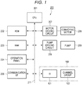
- FIG. 1 is a block diagram illustrating a hardware configuration of the printer 200.
- the printer 200 is applied to, for example, an office printer, a bar code printer, a POS printer, and an industrial printer.
- the printer 200 includes a central processing unit (CPU) 201, a read only memory (ROM) 202, a random access memory (RAM) 203, an operation panel 204, a communication interface 205, a conveying motor (conveying unit) 206, a motor driving circuit 207, a pump 208, a pump driving circuit 209, and an inkjet head 100.
- the printer 200 includes a bus line 211 such as an address bus and a data bus.
- each of integrated circuits (ICs) 101 for driving the CPU 201, the ROM 202, the RAM 203, the operation panel 204, the communication interface 205, the motor driving circuit 207, the pump driving circuit 209, and the inkjet head 100 is connected to the bus line 211 directly or via an input/output circuit.
- the CPU 201 corresponds to the central portion of the computer.
- the CPU 201 controls each unit in order to realize various functions as the printer 200 according to an operating system and an application program.
- the ROM 202 corresponds to a main storage portion of the computer.
- the ROM 202 stores the above-mentioned operating system and application program.
- the ROM 202 may store data necessary for the CPU 201 to execute a process for controlling each unit.
- the RAM 203 corresponds to a main storage portion of the computer.
- the RAM 203 stores data necessary for the CPU 201 to execute a process.
- the RAM 203 is also used as a work area where information is appropriately rewritten by the CPU 201.
- the work area includes an image memory in which the printing data are loaded.
- the operation panel 204 has an operation unit and a display unit.
- function keys such as a power key, a paper feed key, and an error release key are arranged.
- the display unit can display various states of the printer 200.
- the communication interface 205 receives printing data from a client terminal connected via a network such as a local area network (LAN). For example, when an error occurs in the printer 200, the communication interface 205 transmits a signal notifying the error to the client terminal.
- a network such as a local area network (LAN).
- the motor driving circuit 207 controls the driving of the conveying motor 206.
- the conveying motor 206 functions as a drive source for a conveying mechanism that conveys a recording medium such as printing paper.
- the conveying mechanism starts conveying the recording medium.
- the conveying mechanism conveys the recording medium to a printing position by the inkjet head 100.
- the conveying mechanism discharges the printed recording medium to the outside of the printer 200 from a discharge port (not illustrated).
- the pump driving circuit 209 controls the driving of the pump 208.
- ink in an ink tank (not illustrated) is supplied to the inkjet head 100.
- the IC 101 drives the channel group 102 of the inkjet head 100 based on the printing data.
- the IC 101 is an example of the control circuit.
- the channel group 102 is configured with channels including driving pressure chambers, electrodes, nozzles, and the like, which will be described later. That is, the channel group 102 ejects ink by an operation of each driving pressure chamber in which the actuator expands and contracts based on the driving signal from a head driving circuit 101.
- FIGS. 2 to 4 illustrate a shear-mode side shooter type inkjet head 100.
- FIG. 2 is a perspective view illustrating a schematic configuration of the inkjet head 100.
- FIG. 3 is a partial cross-sectional view illustrating an internal structure of the inkjet head 100.
- FIG. 4 is a cross-sectional view illustrating the configuration of the inkjet head 100.
- the inkjet head 100 has an independently driven actuator. As illustrated in FIGS. 2 to 4 , the inkjet head 100 includes a nozzle head unit 2, a flexible printed wiring board 3, and a driving circuit board 4. In addition, the nozzle head unit 2 includes a nozzle plate 21, a substrate 22, a frame member 23 forming the common ink chamber, and an ink supply unit 24 for supplying ink to the common ink chamber.
- the nozzle plate 21 is a rectangular plate made of, for example, a resin such as polyimide or a metal such as stainless steel.
- a plurality of nozzles 25, which are ejection holes for ejecting ink droplets are punctuated on the surface of the nozzle plate 21.
- the nozzle density of the nozzle plate 21 is set, for example, in the range of 150 to 1200 dpi.
- the substrate 22 is, for example, a rectangular substrate made of insulating ceramics.
- the frame member 23 is formed in a box shape that surrounds the lower portion of the substrate 22, for example, laterally symmetrically.
- the opening on the lower surface of the frame member 23 is sealed by the nozzle plate 21.
- the space partitioned by the frame member 23, the substrate 22, and the nozzle plate 21 becomes a common ink chamber 26 (26A and 26B).
- Two common ink chambers 26A and 26B with the substrate 22 interposed therebetween are formed in the common ink chamber 26.
- An ink supply port 27 which is, for example, a circular opening is formed in the frame member 23 on the common ink chamber 26A side.
- the common ink chamber 26A in which the ink supply port 27 is formed serves as an ink supply path for supplying ink to a plurality of driving pressure chambers 5 which will be described later.
- the ink supply port 27 communicates with an ink supply pipe 28 provided to the ink supply unit 24.
- the ink supply pipe 28 further communicates with an ink supply pressure adjusting device.
- an ink discharge port which is, for example, a circular opening is formed in the frame member 23 on the common ink chamber 26B side.
- the ink discharge port communicates with an ink discharge pipe 29 provided to the ink supply unit 24.
- the ink discharge pipe 29 further communicates with the ink supply pressure adjusting device for circulation supply.
- the frame member 23, the ink supply unit 24, the ink supply pipe 28, and the ink discharge pipe 29 are made of, for example, a resin.
- a supporting member 24a having a symmetrical structure with respect to the ink supply unit 24 is arranged at a symmetrical position with the substrate 22 interposed therebetween.
- a fixing member 24b used when the inkjet head 100 is attached to the printer 200 is provided to each of the ink supply unit 24 and the supporting member 24a.
- the plurality of driving pressure chambers 5 constituting an ink ejection channel and a plurality of air chambers 50 constituting dummy channels are arranged on the surface of the substrate 22 located in the common ink chamber 26 (26A and 26B).
- the driving pressure chambers 5 and the air chambers 50 are separated by a piezoelectric member 6 (6A and 6B) which is side walls formed at a height in contact with the surface of the nozzle plate 21.
- the driving pressure chambers 5 and the air chambers 50 are formed by grooves of two piezoelectric members 6A and 6B laminated on the surface of the substrate 22 notched in a rectangular shape in the width direction of the substrate.
- the two piezoelectric members 6A and 6B are laminated in the direction in which the polarization directions are opposite to each other (for example, in opposite directions).
- a piezoelectric material having a large hysteresis is used for the piezoelectric member 6 (6A and 6B).
- the driving pressure chambers 5 and the air chambers 50 are arranged so that the air chambers 50 are located on both sides of the driving pressure chambers 5.
- Each driving pressure chambers 5 is arranged so as to communicate with each nozzle 25 in a one-to-one correspondence manner.
- cover plates 7 constituting the side wall on the short side of the air chambers 50 are arranged on both side surfaces of the substrate 22.
- the lower end surface of the cover plate 7 is at the same height as the fore end surface of the piezoelectric member 6 (6A and 6B) constituting the side wall, and the upper end surface of the cover plate 7 extends to the outside of the common ink chamber 26 (26A and 26B).
- the air chambers 50 constitute a closed space that is shielded from the common ink chambers 26 (26A, 26B) by the cover plate 7.
- the cover plate 7 is formed of, for example, a zirconia plate having a thickness of about 50 ⁇ m.
- groove-shaped openings 71 corresponding to the shape of the driving pressure chambers 5 so that the driving pressure chambers 5 and the left and right common ink chambers 26A and 26B communicate with each other are formed in the cover plate 7.
- the opening 71 of the cover plate 7 on the common ink chamber 26A side is an ink supply port
- the opening 71 of the cover plate 7 on the common ink chamber 26B side is an ink discharge port
- ink is supplied to the driving pressure chambers 5 in a circulating manner.
- the electrode 61 is integrally formed on the upper surface and both side surfaces of the driving pressure chamber 5, and similarly, the electrode 62 is integrally formed on the upper surface and both side surfaces of the air chamber 50.
- Wiring electrodes 63 and 64 extending along the side surface of the substrate 22 to the outside of the common ink chamber 26 (26A and 26B) are connected to the electrode 61 of the driving pressure chamber 5 and the electrode 62 of the air chamber 50, respectively.
- the electrodes 61 and 62 and the wiring electrodes 63 and 64 are formed of, for example, a nickel thin film.
- the driving electric field is applied by using the electrodes 61 connected to the driving pressure chambers 5 as individual electrodes, and the electrodes 62 connected to the air chambers 50 are used as a common electrode, for example, to be grounded.
- the wiring electrode 63 from the driving pressure chambers 5 and the wiring electrode 64 from the air chambers 50 are connected to the flexible printed wiring board 3, and further, electrically connected to the driving circuit board 4 serving as a driving circuit for the ejection operation.
- the above-mentioned drive IC 101 is mounted on the flexible printed wiring board 3.
- the plurality of driving pressure chambers 5 communicate with the nozzle 25 to eject ink droplets.
- the plurality of air chambers 50 are alternately adjacent to each of the plurality of driving pressure chambers 5 one by one.
- the plurality of air chambers 50 do not eject ink droplets.
- the electrodes 61 are provided to the plurality of driving pressure chambers 5.
- the electrodes 62 are provided to the plurality of air chambers 50.
- an independently driven actuator is configured in which a driving electric field is applied in a direction intersecting (preferably, perpendicular to) the polarization axis of the piezoelectric member 6 (6A and 6B) to deform the piezoelectric member 6 (6A and 6B) in shear mode, and ink droplets are ejected from the nozzles 25.
- FIG. 5 is a horizontal cross-sectional view illustrating the configuration of the above-mentioned inkjet head 100.
- the first driving pressure chamber 51 and the second driving pressure chamber 52 are illustrated.
- An electrode 611 is provided to the first driving pressure chamber 51.
- the first driving pressure chamber 51 communicates with the first nozzle 251.
- the second driving pressure chamber 52 is a driving pressure chamber which is adjacent to the first driving pressure chamber 51 with an air chamber 501 adjacent to the first driving pressure chamber 51 interposed therebetween.
- An electrode 612 is provided to the second driving pressure chamber 52.
- the second driving pressure chamber 52 communicates with the second nozzle 252.
- the electrode 612 is provided to the air chamber 501.
- the IC 101 applies a driving signal to the electrode 611 provided to the first driving pressure chamber 51.
- the piezoelectric member 6 adjacent to the first driving pressure chamber 51 is displaced by the action of an electric field due to the driving signal applied to the electrode 611.
- the volume of the first driving pressure chamber 51 contracts or expands due to the displacement of the piezoelectric member 6 adjacent to the first driving pressure chamber 51. Due to the contraction of the volume of the first driving pressure chamber 51, the first nozzle 251 is allowed to eject ink.
- FIG. 6 is a diagram illustrating a state in which the first nozzle 251 is driven.
- the state in which the first nozzle 251 is driven is a state in which the volume of the first driving pressure chamber 51 is contracted.
- the arrow indicates the displacement direction of the piezoelectric members 6. a to i indicate positions in the common ink chamber 26B.
- FIG. 7 is a graph illustrating the amplitude of propagation of the pressure in the common ink chamber 26B in the state in which the first nozzle 251 illustrated in FIG. 6 is driven.
- the horizontal axis indicates the position in the common ink chamber 26B.
- the vertical axis indicates the amplitude of propagation of the pressure.
- the propagation of the pressure generated in the first driving pressure chamber 51 is transmitted to the common ink chamber 26B.
- a pressurizing portion and a depressurizing portion for the propagation of the pressure are generated according to the position of the common ink chamber 26B.
- a complicated propagation wave of the pressure is formed according to the shape of the bottom surface of the common ink chamber 26B and the shape of the portion facing the first driving pressure chamber 51.
- the actual propagation wave of the pressure has a period of half the length of the first driving pressure chamber 51 and, thus, is complicated by the number of driving pressure chambers 5.
- the vibration transmitted to the common ink chamber 26B is attenuated by the structural portion and the physical properties of the ink, and the amplitude of propagation of the pressure decreases as the distance from the driving first driving pressure chamber 51 increases.
- the propagation of the pressure generated in the first driving pressure chamber 51 is also transmitted to the common ink chamber 26A.
- the amplitude of propagation of the pressure for each position of the common ink chamber 26A is the same as the graph illustrated in FIG. 7 .
- first nozzle 251 and the second nozzle 252 are driven in opposite phases.
- the fact that the first nozzle 251 and the second nozzle 252 are driven in opposite phases corresponds to the fact that the timing at which the first driving pressure chamber 51 and the second driving pressure chamber 52 expand or contract are in opposite phases.
- FIG. 8 is a diagram illustrating driving signals for driving the first nozzle 251 and the second nozzle 252 in opposite phases.
- the driving pressure chamber 5 expands due to the displacement of the adjacent piezoelectric members 6.
- the driving pressure chamber 5 contracts due to the displacement of the adjacent piezoelectric members 6.
- the IC 101 allows the timing of applying the driving signal to the electrode 611 and the timing of applying the driving signal to the electrode 612 to be different from each other so that the first nozzle 251 and the second nozzle 252 are driven in opposite phases.
- the timing of applying the driving signal to the electrode 611 and the timing of applying the driving signal to the electrode 612 correspond to a driving start time illustrated in FIG. 8 .
- a time difference between the timing of starting the driving signal applied to the electrode 611 and the timing of starting the driving signal applied to the electrode 612 is a time of propagation of the pressure.
- the time of propagation of the pressure is a time for the pressure wave to propagate from the rear end to the front end of the driving pressure chamber 5.
- the timings of expansion or contraction of the first driving pressure chamber 51 and the second driving pressure chamber 52 are not in opposite phases at the beginning and ending of the driving signal but do not have a large bad influence on the ejection. This is because the beginning and the ending of the driving signal are not the portions in which the ink is directly ejected but is merely due to the fact that the number of nozzles to be driven is reduced.
- FIG. 9 is a diagram illustrating driving of the first nozzle 251 and the second nozzle 252 in opposite phases.
- FIG. 9 illustrates a state in which the volume of the first driving pressure chamber 51 is contracted and the volume of the second driving pressure chamber 52 is expanded.
- the arrow indicates the displacement direction of the piezoelectric members 6.
- a to i indicate positions in the common ink chamber 26B.
- FIG. 10 is a graph illustrating the amplitude of propagation of the pressure in the common ink chamber 26B in the state in which the first nozzle 251 and the second nozzle 252 are driven in opposite phases.
- the horizontal axis indicates the position in the common ink chamber 26B.
- the vertical axis indicates the amplitude of propagation of the pressure.
- the solid line is a graph in the state in which the first nozzle 251 and the second nozzle 252 are driven in opposite phases.
- the broken line is a graph in the state in which the first nozzle 251 and the second nozzle 252 are driven in phase (in the same phase), which is a comparative example.
- first nozzle 251 and the second nozzle 252 are driven in opposite phases.
- the propagation of the pressure generated in the first driving pressure chamber 51 is transmitted to the common ink chamber 26B.
- the propagation of the pressure generated in the second driving pressure chamber 52 is transmitted to the common ink chamber 26B.
- the timings at which the first driving pressure chamber 51 and the second driving pressure chamber 52 contract or expand are in opposite phases.
- the propagation of the pressure generated in the first driving pressure chamber 51 and the propagation of the pressure generated in the second driving pressure chamber 52 are out of phase.
- the time during which the propagation of the pressure generated in the first driving pressure chamber 51 influences the common ink chamber 26B is different from the time during which the propagation of the pressure generated in the second driving pressure chamber 52 influences the common ink chamber 26B.
- the distance between the first driving pressure chamber 51 and the second driving pressure chamber 52 is the same as the period of propagation of the pressure. In this case, the propagation of the pressure transmitted from the first driving pressure chamber 51 to the common ink chamber 26B and the propagation of the pressure transmitted from the second driving pressure chamber 52 to the common ink chamber 26B are allowed to cancel each other.
- the pressurizing portion and the depressurizing portion of the propagation of the pressure are hardly generated irrespective of the position of the common ink chamber 26B. Therefore, the ejection amount from the first nozzle 251 and the second nozzle 252 is stable, and thus, the print quality is improved.
- the propagation of the pressure generated in the first driving pressure chamber 51 and the propagation of the pressure generated in the second driving pressure chamber 52 are also transmitted to the common ink chamber 26A.
- the amplitude of the propagation of the pressure for each position in the common ink chamber 26A is the same as the graph of the solid line illustrated in FIG. 10 .
- the case where the first nozzle 251 and the second nozzle 252 are driven in phase will be described.
- the driving start times of the driving signal applied to the electrode 611 and the driving signal applied to the electrode 612 are the same.
- the timings at which the first driving pressure chamber 51 and the second driving pressure chamber 52 contract or expand are in phase. In the first driving pressure chamber 51 and the second driving pressure chamber 52, similar propagation of the pressure occurs at the same timings. For this reason, the time during which the propagation of the pressure generated in the first driving pressure chamber 51 influences the common ink chamber 26B is the same as the time during which the propagation of the pressure generated in the second driving pressure chamber 52 influences the common ink chamber 26B.
- the distance between the first driving pressure chamber 51 and the second driving pressure chamber 52 is the same as the period of propagation of the pressure.
- the propagation of the pressure transmitted from the first driving pressure chamber 51 to the common ink chamber 26B and the propagation of the pressure transmitted from the second driving pressure chamber 52 to the common ink chamber 26B are allowed to amplify each other.
- a pressurizing portion and a depressurizing portion for the propagation of the pressure are generated according to the position of the common ink chamber 26B. Therefore, the ejection amounts from the first nozzle 251 and the second nozzle 252 are not stable, and thus, the print quality is deteriorated.
- the propagation of the pressure generated in the first driving pressure chamber 51 and the propagation of the pressure generated in the second driving pressure chamber 52 are also transmitted to the common ink chamber 26A.
- the amplitude of the propagation of the pressure for each position in the common ink chamber 26A is the same as the graph of the broken line illustrated in FIG. 10 .
- FIG. 11 is a graph illustrating characteristics of the ejection amount with respect to the line frequency when the first nozzle 251 and the second nozzle 252 are driven in opposite phases.
- the horizontal axis indicates a line frequency which is the reciprocal of the period of one line.
- the vertical axis indicates the ejection amount.
- the ejection amount from the first nozzle 251 and the second nozzle 252 is stable irrespective of the line frequency.
- the variation in the ejection amount from the first nozzle 251 and the second nozzle 252 does not occur irrespective of the line frequency. For this reason, the print quality is not deteriorated irrespective of the line frequency.
- characteristics of the ejection amount with respect to the line frequency when the first nozzle 251 and the second nozzle 252 are driven in phase will be described.
- a variation in the ejection amount from the first nozzle 251 and the second nozzle 252 occurs.
- the variation in the ejection amount from the first nozzle 251 and the second nozzle 252 becomes large. For this reason, the print quality is deteriorated due to crosstalk. Since the ejection amount from the first nozzle 251 and the second nozzle 252 is not stable, it is difficult to control the ejection amount.
- first nozzle 251 and the second nozzle 252 may not be driven in phase.
- the first nozzle 251 and the second nozzle 252 are not limited to being driven in opposite phases described above. Therefore, in the IC 101, the timing of applying the driving signal to the electrode 611 and the timing of applying the driving signal to the electrode 612 may be allowed to be different from each other so that the first nozzle 251 and the second nozzle 252 are not driven in phase.
- the IC 101 allows the timings of starting the driving signals applied to the electrodes 61 provided to the driving pressure chambers 5 with the same remainder according to 2 in order of counting the plurality of driving pressure chambers 5 arranged in one direction from one end side, among the plurality of driving pressure chambers 5, to be the same. That is, the head driving circuit 101 allows the timings of starting the driving signals applied to the electrodes 61 provided to the set of driving pressure chambers 5 in which the remainder according to 2 in order is 0 to be the same.
- the head driving circuit 101 allows the timings of starting the driving signals applied to the electrodes 61 provided to the set of driving pressure chambers 5 in which the remainder according to 2 in order is 1 to be the same.
- the IC 101 allows the timing of the set with a remainder of 0 and the timing of the set with a remainder of 1 to be different from each other.
- the set in which the remainder according to 2 in order is 0 corresponds to the set of even-numbered driving pressure chambers 5 in which the plurality of driving pressure chambers 5 arranged in one direction are counted from one end side.
- the set in which the remainder according to 2 in order is 1 corresponds to the set of odd-numbered driving pressure chambers 5 in which the plurality of driving pressure chambers 5 arranged in one direction are counted from one end side.
- FIG. 12 is a diagram illustrating the configuration example of the IC 101.
- the IC 101 includes a logic unit (logic circuit) 1011 and a level shift unit (level shifter) 1012 and an output unit 1013.
- the logic unit 1011 processes the input signal.
- the input signal is configured with control commands for instructing control, setting data for determining a driving signal according to the gradation, and printing data for selecting the gradation of each output circuit included in the output unit 1013.
- the control commands include a printing trigger.
- the logic unit 1011 includes an interface unit 10111, a shift register unit 10112, and a latch unit 10113. Furthermore, the logic unit 1011 includes a setting circuit (not illustrated) that determines an output corresponding to the gradation data.
- the interface unit 10111 receives the input signal and supplies the setting data and the printing data to the shift register unit 10112.
- the interface unit 10111 supplies the printing trigger as a driving start signal to the latch unit 10113.
- the shift register unit 10112 temporarily stores the setting data and the printing data.
- the shift register unit 10112 supplies the stored setting data and printing data to the latch unit 10113 in order in which the setting data and the printing data are stored.
- the latch unit 10113 stores the setting data and the printing data.
- the latch unit 10113 includes a plurality of latch circuits corresponding to the respective output circuits included in the output unit 1013.
- the plurality of latch circuits correspond to the plurality of electrodes 61 and the plurality of electrodes 62.
- the plurality of latch circuits supply the driving signal corresponding to the gradation data to the level shift unit 1012 based on the setting data and the printing data, starting from the driving start signal indicating the driving start of the driving start signal.
- the latch unit 10113 includes a delay circuit 10114.
- the delay circuit 10114 delays the driving start signal and supplies the driving start signal to a portion of the latch circuits.
- the delay circuit 10114 outputs the driving start signal delayed with a time according to the setting data. That is, the delay circuit 10114 is a circuit that delays the timing of starting the driving signal applied to the electrodes 61 provided to each of the driving pressure chambers 5.
- the delay circuit 10114 may be a digital delay circuit or an analog delay circuit.
- the delay circuit 10114 is connected to a latch circuit corresponding to either the electrode 611 provided to the first driving pressure chamber 51 or the electrode 612 provided to the second driving pressure chamber 52.
- the delay circuit 10114 delays the timing of starting the driving signal applied to either the electrode 611 provided to the first driving pressure chamber 51 or the electrode 612 provided to the second driving pressure chamber 52.
- the delay circuit 10114 is connected to the latch circuits corresponding to the electrodes 61 provided to the driving pressure chambers 5 of either a set of 0 or a set of 1 with a remainder according to 2 in order of counting the plurality of driving pressure chambers 5 arranged in one direction from one end side.
- the delay circuit 10114 delays the timing of starting the driving signals applied to the electrodes 61 provided to the driving pressure chambers 5 of either the set of 0 or the set of 1 with a remainder according to 2 in order.
- the level shift unit 1012 converts the voltage level of the driving signal supplied from the latch unit 10113 by using the power supply voltage.
- the level shift unit 1012 supplies the driving signal of which voltage level is converted to the output unit 1013.
- the output unit 1013 outputs the driving signal to the electrode 61 provided to each of the plurality of driving pressure chambers 5.
- the output unit 1013 includes an output circuit corresponding to the electrode 61 provided to each of the plurality of driving pressure chambers 5.
- the delay circuit 10114 is provided, so that the IC 101 can delay the timing of starting the driving signal applied to a portion of the electrodes 61.
- the RAM 203 stores the setting data including the gradation data.
- the RAM 203 stores the printing data.
- the RAM 203 is an example of a memory area.
- the CPU 201 refers to the setting data and rewrites a portion of the printing data based on the gradation that delays the driving signal.
- the CPU 201 is an example of a circuit that rewrites a portion of the printing data.
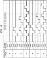
- FIG. 13 is a diagram illustrating the driving signals according to the gradation values.
- the CPU 201 allocates the driving signals to the gradations that delay a portion of the printing data.
- the 1 to 3 gradations are set so that the IC 101 outputs the driving signals of 1 to 3 drops.
- the 4 to 6 gradations are set so that the IC 101 outputs the driving signals of delayed 1 to 3 drops.
- the input gradation value is proportional to the number of drops and the amount of droplets, but the input gradation value does not match the number of drops and the amount of droplets in the case of this embodiment. For this reason, the CPU 201 needs to recognize the gradations that delay the driving signals. Therefore, the CPU 201 can rewrite a portion of the printing data based on the gradations that delay the driving signals.
- the IC 101 is configured in the same manner as the example of FIG. 12 except that the IC 101 does not include the delay circuit 10114.
- the interface unit 10111 receives the setting data including the gradation data from the RAM 203.
- the interface unit 10111 receives printing data partially rewritten from the RAM 203 based on the gradations that delay the driving signals by the CPU 201.
- the shift register unit 10112 stores the setting data including the gradation data.
- the shift register unit 10112 stores the printing data.
- the shift register unit 10112 is an example of a memory area.
- the IC 101 (for example, the latch unit 10113) generates the driving signals based on the setting data and the printing data. In this manner, the IC 101 can delay the timing of starting the driving signals applied to a portion of the electrodes 61.
- the ink circulation type inkjet head 100 is described as an example, but an ink non-circulation type inkjet head may be used.
- the inkjet head 100 may be mounted on a 3D printer. In this case, a liquid molding material or supporting material is ejected as ink.
Landscapes
- Particle Formation And Scattering Control In Inkjet Printers (AREA)
- Ink Jet (AREA)
Abstract
Description
- Embodiments described herein relate generally to an inkjet head and an inkjet printer.
- There is an inkjet head having an independently driven actuator, including a driving pressure chamber communicating with a common ink chamber and nozzles, and adjacent pressure chambers provided on both sides of the driving pressure chamber via side walls.
- In addition, there is an inkjet head having a structure in which an adjacent pressure chamber is formed into an air chamber by closing a portion of the adjacent pressure chamber in contact with a common ink chamber. A driving circuit allows ink to be ejected by applying a driving waveform that pressurizes or depressurizes and, after that, pressurizes the driving pressure chamber by driving a piezoelectric member.
- Since the driving pressure chamber communicates with the common ink chamber, propagation of a pressure generated in the driving pressure chamber is transmitted to the common ink chamber and influences other driving pressure chambers. If this influence cannot be removed, the print quality is deteriorated due to crosstalk caused by propagation of the pressure in the common ink chamber.
- If the adjacent pressure chambers are filled with ink, the propagation of the pressure, which is in phase opposite to the propagation of the pressure generated in the driving pressure chamber and has half the amplitude, is generated in each adjacent pressure chamber. The propagation of the pressure transmitted from the driving pressure chamber to the common ink chamber is canceled by the propagation of the pressure transmitted from the adjacent pressure chambers on both sides to the common ink chamber. In this case, the crosstalk caused by the propagation of the pressure in the common ink chamber is not generated.
- However, if the adjacent pressure chamber is an air chamber, the propagation of the pressure is not transmitted from the adjacent pressure chamber to the common ink chamber. The propagation of the pressure transmitted from the driving pressure chamber to the common ink chamber is transmitted to other driving pressure chambers, which causes deterioration of print quality due to crosstalk. If there are a plurality of driving pressure chambers to be driven, the propagation of the pressure generated in the common ink chamber is amplified or attenuated by a distance between the driving pressure chambers, a propagation time (AL) of the pressure, and a phase and attenuation of pressure vibration.
-
-
FIG. 1 is a block diagram illustrating a hardware configuration of an inkjet printer according to an embodiment; -
FIG. 2 is a perspective view illustrating a schematic configuration of an inkjet head according to the embodiment; -
FIG. 3 is a partial cross-sectional view illustrating an internal structure of the inkjet head according to the embodiment; -
FIG. 4 is a cross-sectional view illustrating a configuration of the inkjet head according to the embodiment; -
FIG. 5 is a horizontal cross-sectional view illustrating the configuration of the inkjet head according to the embodiment; -
FIG. 6 is a diagram illustrating driving of one nozzle according to the embodiment; -
FIG. 7 is a graph illustrating an amplitude of propagation of the pressure in the common ink chamber according to the embodiment; -
FIG. 8 is a diagram illustrating driving signals for driving two nozzles according to the embodiment in opposite phases; -
FIG. 9 is a diagram illustrating driving of two nozzles according to the embodiment in opposite phases; -
FIG. 10 is a graph illustrating an amplitude of propagation of the pressure in the common ink chamber according to the embodiment; -
FIG. 11 is a graph illustrating characteristics of an ejection amount with respect to a line frequency according to the embodiment; -
FIG. 12 is a diagram illustrating a configuration example of an IC according to an embodiment; and -
FIG. 13 is a diagram illustrating driving signals according to gradation values in the embodiment. - An object to be solved by embodiments is to prevent deterioration of print quality due to crosstalk.
- In general, according to one embodiment, an inkjet head includes a plurality of pressure chambers, a plurality of air chambers, electrodes, and a control circuit. The plurality of pressure chambers communicate with the nozzle and eject ink droplets. The plurality of air chambers are alternately adjacent to each of the plurality of pressure chambers one by one and do not eject ink droplets. The electrodes are provided to the plurality of pressure chambers. The control circuit allows a timing of starting a driving signal applied to the electrode provided to a first pressure chamber among the plurality of pressure chambers and a timing of starting a driving signal applied to the electrode provided to a second pressure chamber which is adjacent to the first pressure chamber with the air chamber adjacent to the first pressure chamber interposed therebetween to be different from each other.
- Preferably, the control circuit allows timings of starting the driving signals applied to the electrodes provided to the pressure chamber with the same remainder according to 2 in order of counting the plurality of pressure chambers arranged in one direction from one end side, among the plurality of pressure chambers, to be the same.
- Preferably, a time difference between the timing of starting the driving signal applied to the electrode provided to the first pressure chamber and the timing of starting the driving signal applied to the electrode provided to the second pressure chamber is a time of propagation of pressure.
- Preferably, the control circuit includes a circuit that delays the timing of starting the driving signal applied to the electrode provided to each of the pressure chambers.
- There is also provided an inkjet printer comprising: the inkjet head as described above; a memory area that stores setting data including gradation data; and a circuit that rewrites a portion of printing data based on a gradation that delays the driving signal, wherein the control circuit of the inkjet head generates the driving signals based on the setting data and the printing data.
- Hereinafter, embodiments will be described with reference to the drawings.
- A configuration of an inkjet printer 200 (hereinafter, abbreviated as a printer 200) will be described with reference to
FIG. 1. FIG. 1 is a block diagram illustrating a hardware configuration of theprinter 200. Theprinter 200 is applied to, for example, an office printer, a bar code printer, a POS printer, and an industrial printer. - The
printer 200 includes a central processing unit (CPU) 201, a read only memory (ROM) 202, a random access memory (RAM) 203, anoperation panel 204, acommunication interface 205, a conveying motor (conveying unit) 206, amotor driving circuit 207, apump 208, apump driving circuit 209, and aninkjet head 100. In addition, theprinter 200 includes abus line 211 such as an address bus and a data bus. In theprinter 200, each of integrated circuits (ICs) 101 for driving theCPU 201, theROM 202, theRAM 203, theoperation panel 204, thecommunication interface 205, themotor driving circuit 207, thepump driving circuit 209, and theinkjet head 100 is connected to thebus line 211 directly or via an input/output circuit. - The
CPU 201 corresponds to the central portion of the computer. TheCPU 201 controls each unit in order to realize various functions as theprinter 200 according to an operating system and an application program. - The
ROM 202 corresponds to a main storage portion of the computer. TheROM 202 stores the above-mentioned operating system and application program. In some cases, theROM 202 may store data necessary for theCPU 201 to execute a process for controlling each unit. - The
RAM 203 corresponds to a main storage portion of the computer. TheRAM 203 stores data necessary for theCPU 201 to execute a process. In addition, theRAM 203 is also used as a work area where information is appropriately rewritten by theCPU 201. The work area includes an image memory in which the printing data are loaded. - The
operation panel 204 has an operation unit and a display unit. In the operation unit, function keys such as a power key, a paper feed key, and an error release key are arranged. The display unit can display various states of theprinter 200. - The
communication interface 205 receives printing data from a client terminal connected via a network such as a local area network (LAN). For example, when an error occurs in theprinter 200, thecommunication interface 205 transmits a signal notifying the error to the client terminal. - The
motor driving circuit 207 controls the driving of the conveyingmotor 206. The conveyingmotor 206 functions as a drive source for a conveying mechanism that conveys a recording medium such as printing paper. When the conveyingmotor 206 is driven, the conveying mechanism starts conveying the recording medium. The conveying mechanism conveys the recording medium to a printing position by theinkjet head 100. The conveying mechanism discharges the printed recording medium to the outside of theprinter 200 from a discharge port (not illustrated). - The
pump driving circuit 209 controls the driving of thepump 208. When thepump 208 is driven, ink in an ink tank (not illustrated) is supplied to theinkjet head 100. - The
IC 101 drives thechannel group 102 of theinkjet head 100 based on the printing data. TheIC 101 is an example of the control circuit. Thechannel group 102 is configured with channels including driving pressure chambers, electrodes, nozzles, and the like, which will be described later. That is, thechannel group 102 ejects ink by an operation of each driving pressure chamber in which the actuator expands and contracts based on the driving signal from ahead driving circuit 101. - Subsequently, the configuration of the
inkjet head 100 will be described with reference toFIGS. 2 to 4. FIGS. 2 to 4 illustrate a shear-mode side shootertype inkjet head 100. -
FIG. 2 is a perspective view illustrating a schematic configuration of theinkjet head 100. -
FIG. 3 is a partial cross-sectional view illustrating an internal structure of theinkjet head 100. -
FIG. 4 is a cross-sectional view illustrating the configuration of theinkjet head 100. - The
inkjet head 100 has an independently driven actuator. As illustrated inFIGS. 2 to 4 , theinkjet head 100 includes anozzle head unit 2, a flexible printedwiring board 3, and a driving circuit board 4. In addition, thenozzle head unit 2 includes anozzle plate 21, asubstrate 22, aframe member 23 forming the common ink chamber, and anink supply unit 24 for supplying ink to the common ink chamber. - The
nozzle plate 21 is a rectangular plate made of, for example, a resin such as polyimide or a metal such as stainless steel. A plurality ofnozzles 25, which are ejection holes for ejecting ink droplets are punctuated on the surface of thenozzle plate 21. The nozzle density of thenozzle plate 21 is set, for example, in the range of 150 to 1200 dpi. Thesubstrate 22 is, for example, a rectangular substrate made of insulating ceramics. - The
frame member 23 is formed in a box shape that surrounds the lower portion of thesubstrate 22, for example, laterally symmetrically. The opening on the lower surface of theframe member 23 is sealed by thenozzle plate 21. The space partitioned by theframe member 23, thesubstrate 22, and thenozzle plate 21 becomes a common ink chamber 26 (26A and 26B). Twocommon ink chambers substrate 22 interposed therebetween are formed in thecommon ink chamber 26. Anink supply port 27 which is, for example, a circular opening is formed in theframe member 23 on thecommon ink chamber 26A side. Thecommon ink chamber 26A in which theink supply port 27 is formed serves as an ink supply path for supplying ink to a plurality of drivingpressure chambers 5 which will be described later. Theink supply port 27 communicates with anink supply pipe 28 provided to theink supply unit 24. Theink supply pipe 28 further communicates with an ink supply pressure adjusting device. On the other hand, although not illustrated, similarly to theink supply port 27, an ink discharge port which is, for example, a circular opening is formed in theframe member 23 on thecommon ink chamber 26B side. The ink discharge port communicates with anink discharge pipe 29 provided to theink supply unit 24. Theink discharge pipe 29 further communicates with the ink supply pressure adjusting device for circulation supply. Theframe member 23, theink supply unit 24, theink supply pipe 28, and theink discharge pipe 29 are made of, for example, a resin. In addition, except that theink supply pipe 28 and theink discharge pipe 29 are not provided, a supportingmember 24a having a symmetrical structure with respect to theink supply unit 24 is arranged at a symmetrical position with thesubstrate 22 interposed therebetween. A fixingmember 24b used when theinkjet head 100 is attached to theprinter 200 is provided to each of theink supply unit 24 and the supportingmember 24a. - The plurality of driving
pressure chambers 5 constituting an ink ejection channel and a plurality ofair chambers 50 constituting dummy channels are arranged on the surface of thesubstrate 22 located in the common ink chamber 26 (26A and 26B). The drivingpressure chambers 5 and theair chambers 50 are separated by a piezoelectric member 6 (6A and 6B) which is side walls formed at a height in contact with the surface of thenozzle plate 21. The drivingpressure chambers 5 and theair chambers 50 are formed by grooves of twopiezoelectric members substrate 22 notched in a rectangular shape in the width direction of the substrate. The twopiezoelectric members pressure chambers 5 and theair chambers 50 are arranged so that theair chambers 50 are located on both sides of the drivingpressure chambers 5. Each drivingpressure chambers 5 is arranged so as to communicate with eachnozzle 25 in a one-to-one correspondence manner. - Furthermore, two
cover plates 7 constituting the side wall on the short side of theair chambers 50 are arranged on both side surfaces of thesubstrate 22. The lower end surface of thecover plate 7 is at the same height as the fore end surface of the piezoelectric member 6 (6A and 6B) constituting the side wall, and the upper end surface of thecover plate 7 extends to the outside of the common ink chamber 26 (26A and 26B). Theair chambers 50 constitute a closed space that is shielded from the common ink chambers 26 (26A, 26B) by thecover plate 7. Thecover plate 7 is formed of, for example, a zirconia plate having a thickness of about 50 µm. On the other hand, groove-shapedopenings 71 corresponding to the shape of the drivingpressure chambers 5 so that the drivingpressure chambers 5 and the left and rightcommon ink chambers cover plate 7. Theopening 71 of thecover plate 7 on thecommon ink chamber 26A side is an ink supply port, theopening 71 of thecover plate 7 on thecommon ink chamber 26B side is an ink discharge port, and ink is supplied to the drivingpressure chambers 5 in a circulating manner. - If the ink used is, for example, an insulating ink, as illustrated in
FIG. 4 , theelectrode 61 is integrally formed on the upper surface and both side surfaces of the drivingpressure chamber 5, and similarly, theelectrode 62 is integrally formed on the upper surface and both side surfaces of theair chamber 50.Wiring electrodes substrate 22 to the outside of the common ink chamber 26 (26A and 26B) are connected to theelectrode 61 of the drivingpressure chamber 5 and theelectrode 62 of theair chamber 50, respectively. Theelectrodes wiring electrodes electrodes 61 connected to the drivingpressure chambers 5 as individual electrodes, and theelectrodes 62 connected to theair chambers 50 are used as a common electrode, for example, to be grounded. - Returning to
FIG. 2 , thewiring electrode 63 from the drivingpressure chambers 5 and thewiring electrode 64 from theair chambers 50 are connected to the flexible printedwiring board 3, and further, electrically connected to the driving circuit board 4 serving as a driving circuit for the ejection operation. The above-mentioneddrive IC 101 is mounted on the flexible printedwiring board 3. - As described above, the plurality of driving
pressure chambers 5 communicate with thenozzle 25 to eject ink droplets. The plurality ofair chambers 50 are alternately adjacent to each of the plurality of drivingpressure chambers 5 one by one. The plurality ofair chambers 50 do not eject ink droplets. Theelectrodes 61 are provided to the plurality of drivingpressure chambers 5. Theelectrodes 62 are provided to the plurality ofair chambers 50. - With the above-described configuration, an independently driven actuator is configured in which a driving electric field is applied in a direction intersecting (preferably, perpendicular to) the polarization axis of the piezoelectric member 6 (6A and 6B) to deform the piezoelectric member 6 (6A and 6B) in shear mode, and ink droplets are ejected from the
nozzles 25. -
FIG. 5 is a horizontal cross-sectional view illustrating the configuration of the above-mentionedinkjet head 100. - Herein, among the plurality of driving
pressure chambers 5, the firstdriving pressure chamber 51 and the seconddriving pressure chamber 52 are illustrated. Anelectrode 611 is provided to the firstdriving pressure chamber 51. The firstdriving pressure chamber 51 communicates with thefirst nozzle 251. The seconddriving pressure chamber 52 is a driving pressure chamber which is adjacent to the firstdriving pressure chamber 51 with anair chamber 501 adjacent to the firstdriving pressure chamber 51 interposed therebetween. Anelectrode 612 is provided to the seconddriving pressure chamber 52. The seconddriving pressure chamber 52 communicates with thesecond nozzle 252. Theelectrode 612 is provided to theair chamber 501. - First, an example in which only the
first nozzle 251 is driven will be described. - The
IC 101 applies a driving signal to theelectrode 611 provided to the firstdriving pressure chamber 51. Thepiezoelectric member 6 adjacent to the firstdriving pressure chamber 51 is displaced by the action of an electric field due to the driving signal applied to theelectrode 611. The volume of the firstdriving pressure chamber 51 contracts or expands due to the displacement of thepiezoelectric member 6 adjacent to the firstdriving pressure chamber 51. Due to the contraction of the volume of the firstdriving pressure chamber 51, thefirst nozzle 251 is allowed to eject ink. -
FIG. 6 is a diagram illustrating a state in which thefirst nozzle 251 is driven. - The state in which the
first nozzle 251 is driven is a state in which the volume of the firstdriving pressure chamber 51 is contracted. The arrow indicates the displacement direction of thepiezoelectric members 6. a to i indicate positions in thecommon ink chamber 26B. -
FIG. 7 is a graph illustrating the amplitude of propagation of the pressure in thecommon ink chamber 26B in the state in which thefirst nozzle 251 illustrated inFIG. 6 is driven. The horizontal axis indicates the position in thecommon ink chamber 26B. The vertical axis indicates the amplitude of propagation of the pressure. - As can be seen from
FIG. 7 , the propagation of the pressure generated in the firstdriving pressure chamber 51 is transmitted to thecommon ink chamber 26B. In addition, according to the position of thecommon ink chamber 26B, a pressurizing portion and a depressurizing portion for the propagation of the pressure are generated. It should be noted that, actually, a complicated propagation wave of the pressure is formed according to the shape of the bottom surface of thecommon ink chamber 26B and the shape of the portion facing the firstdriving pressure chamber 51. The actual propagation wave of the pressure has a period of half the length of the firstdriving pressure chamber 51 and, thus, is complicated by the number of drivingpressure chambers 5. The vibration transmitted to thecommon ink chamber 26B is attenuated by the structural portion and the physical properties of the ink, and the amplitude of propagation of the pressure decreases as the distance from the driving first drivingpressure chamber 51 increases. - It should be noted that the propagation of the pressure generated in the first
driving pressure chamber 51 is also transmitted to thecommon ink chamber 26A. The amplitude of propagation of the pressure for each position of thecommon ink chamber 26A is the same as the graph illustrated inFIG. 7 . - Next, an example in which the
first nozzle 251 and thesecond nozzle 252 are driven in opposite phases will be described. The fact that thefirst nozzle 251 and thesecond nozzle 252 are driven in opposite phases corresponds to the fact that the timing at which the firstdriving pressure chamber 51 and the seconddriving pressure chamber 52 expand or contract are in opposite phases. -
FIG. 8 is a diagram illustrating driving signals for driving thefirst nozzle 251 and thesecond nozzle 252 in opposite phases. - When the driving voltage of -VAA is applied to the
electrode 61 provided to the drivingpressure chamber 5, the drivingpressure chamber 5 expands due to the displacement of the adjacentpiezoelectric members 6. When the driving voltage of the VAA is applied to theelectrode 61 provided to the drivingpressure chamber 5, the drivingpressure chamber 5 contracts due to the displacement of the adjacentpiezoelectric members 6. - The
IC 101 allows the timing of applying the driving signal to theelectrode 611 and the timing of applying the driving signal to theelectrode 612 to be different from each other so that thefirst nozzle 251 and thesecond nozzle 252 are driven in opposite phases. The timing of applying the driving signal to theelectrode 611 and the timing of applying the driving signal to theelectrode 612 correspond to a driving start time illustrated inFIG. 8 . - In a typical example, a time difference between the timing of starting the driving signal applied to the
electrode 611 and the timing of starting the driving signal applied to theelectrode 612 is a time of propagation of the pressure. Herein, the time of propagation of the pressure is a time for the pressure wave to propagate from the rear end to the front end of the drivingpressure chamber 5. - It should be noted that the timings of expansion or contraction of the first
driving pressure chamber 51 and the seconddriving pressure chamber 52 are not in opposite phases at the beginning and ending of the driving signal but do not have a large bad influence on the ejection. This is because the beginning and the ending of the driving signal are not the portions in which the ink is directly ejected but is merely due to the fact that the number of nozzles to be driven is reduced. -
FIG. 9 is a diagram illustrating driving of thefirst nozzle 251 and thesecond nozzle 252 in opposite phases. -
FIG. 9 illustrates a state in which the volume of the firstdriving pressure chamber 51 is contracted and the volume of the seconddriving pressure chamber 52 is expanded. The arrow indicates the displacement direction of thepiezoelectric members 6. a to i indicate positions in thecommon ink chamber 26B. -
FIG. 10 is a graph illustrating the amplitude of propagation of the pressure in thecommon ink chamber 26B in the state in which thefirst nozzle 251 and thesecond nozzle 252 are driven in opposite phases. - The horizontal axis indicates the position in the
common ink chamber 26B. The vertical axis indicates the amplitude of propagation of the pressure. - The solid line is a graph in the state in which the
first nozzle 251 and thesecond nozzle 252 are driven in opposite phases. The broken line is a graph in the state in which thefirst nozzle 251 and thesecond nozzle 252 are driven in phase (in the same phase), which is a comparative example. - The case where the
first nozzle 251 and thesecond nozzle 252 are driven in opposite phases will be described. The propagation of the pressure generated in the firstdriving pressure chamber 51 is transmitted to thecommon ink chamber 26B. Similarly, the propagation of the pressure generated in the seconddriving pressure chamber 52 is transmitted to thecommon ink chamber 26B. The timings at which the firstdriving pressure chamber 51 and the seconddriving pressure chamber 52 contract or expand are in opposite phases. The propagation of the pressure generated in the firstdriving pressure chamber 51 and the propagation of the pressure generated in the seconddriving pressure chamber 52 are out of phase. For this reason, the time during which the propagation of the pressure generated in the firstdriving pressure chamber 51 influences thecommon ink chamber 26B is different from the time during which the propagation of the pressure generated in the seconddriving pressure chamber 52 influences thecommon ink chamber 26B. Herein, it is assumed that the distance between the firstdriving pressure chamber 51 and the seconddriving pressure chamber 52 is the same as the period of propagation of the pressure. In this case, the propagation of the pressure transmitted from the firstdriving pressure chamber 51 to thecommon ink chamber 26B and the propagation of the pressure transmitted from the seconddriving pressure chamber 52 to thecommon ink chamber 26B are allowed to cancel each other. For this reason, as illustrated by the solid line, the pressurizing portion and the depressurizing portion of the propagation of the pressure are hardly generated irrespective of the position of thecommon ink chamber 26B. Therefore, the ejection amount from thefirst nozzle 251 and thesecond nozzle 252 is stable, and thus, the print quality is improved. - It should be noted that the propagation of the pressure generated in the first
driving pressure chamber 51 and the propagation of the pressure generated in the seconddriving pressure chamber 52 are also transmitted to thecommon ink chamber 26A. The amplitude of the propagation of the pressure for each position in thecommon ink chamber 26A is the same as the graph of the solid line illustrated inFIG. 10 . - The case where the
first nozzle 251 and thesecond nozzle 252 are driven in phase will be described. The driving start times of the driving signal applied to theelectrode 611 and the driving signal applied to theelectrode 612 are the same. The timings at which the firstdriving pressure chamber 51 and the seconddriving pressure chamber 52 contract or expand are in phase. In the firstdriving pressure chamber 51 and the seconddriving pressure chamber 52, similar propagation of the pressure occurs at the same timings. For this reason, the time during which the propagation of the pressure generated in the firstdriving pressure chamber 51 influences thecommon ink chamber 26B is the same as the time during which the propagation of the pressure generated in the seconddriving pressure chamber 52 influences thecommon ink chamber 26B. Herein, it is assumed that the distance between the firstdriving pressure chamber 51 and the seconddriving pressure chamber 52 is the same as the period of propagation of the pressure. In this case, the propagation of the pressure transmitted from the firstdriving pressure chamber 51 to thecommon ink chamber 26B and the propagation of the pressure transmitted from the seconddriving pressure chamber 52 to thecommon ink chamber 26B are allowed to amplify each other. For this reason, as illustrated by the broken line, a pressurizing portion and a depressurizing portion for the propagation of the pressure are generated according to the position of thecommon ink chamber 26B. Therefore, the ejection amounts from thefirst nozzle 251 and thesecond nozzle 252 are not stable, and thus, the print quality is deteriorated. - It should be noted that the propagation of the pressure generated in the first
driving pressure chamber 51 and the propagation of the pressure generated in the seconddriving pressure chamber 52 are also transmitted to thecommon ink chamber 26A. The amplitude of the propagation of the pressure for each position in thecommon ink chamber 26A is the same as the graph of the broken line illustrated inFIG. 10 . -
FIG. 11 is a graph illustrating characteristics of the ejection amount with respect to the line frequency when thefirst nozzle 251 and thesecond nozzle 252 are driven in opposite phases. - The horizontal axis indicates a line frequency which is the reciprocal of the period of one line. The vertical axis indicates the ejection amount.
- The ejection amount from the
first nozzle 251 and thesecond nozzle 252 is stable irrespective of the line frequency. The variation in the ejection amount from thefirst nozzle 251 and thesecond nozzle 252 does not occur irrespective of the line frequency. For this reason, the print quality is not deteriorated irrespective of the line frequency. - As a reference example, characteristics of the ejection amount with respect to the line frequency when the
first nozzle 251 and thesecond nozzle 252 are driven in phase will be described. At a reference line frequency, a variation in the ejection amount from thefirst nozzle 251 and thesecond nozzle 252 occurs. At a line frequency higher than the reference, the variation in the ejection amount from thefirst nozzle 251 and thesecond nozzle 252 becomes large. For this reason, the print quality is deteriorated due to crosstalk. Since the ejection amount from thefirst nozzle 251 and thesecond nozzle 252 is not stable, it is difficult to control the ejection amount. - It should be noted that the
first nozzle 251 and thesecond nozzle 252 may not be driven in phase. For this reason, thefirst nozzle 251 and thesecond nozzle 252 are not limited to being driven in opposite phases described above. Therefore, in theIC 101, the timing of applying the driving signal to theelectrode 611 and the timing of applying the driving signal to theelectrode 612 may be allowed to be different from each other so that thefirst nozzle 251 and thesecond nozzle 252 are not driven in phase. - In the above description, the first
driving pressure chamber 51 and the seconddriving pressure chamber 52 have been described, but the embodiments are not limited thereto. TheIC 101 allows the timings of starting the driving signals applied to theelectrodes 61 provided to the drivingpressure chambers 5 with the same remainder according to 2 in order of counting the plurality of drivingpressure chambers 5 arranged in one direction from one end side, among the plurality of drivingpressure chambers 5, to be the same. That is, thehead driving circuit 101 allows the timings of starting the driving signals applied to theelectrodes 61 provided to the set of drivingpressure chambers 5 in which the remainder according to 2 in order is 0 to be the same. Thehead driving circuit 101 allows the timings of starting the driving signals applied to theelectrodes 61 provided to the set of drivingpressure chambers 5 in which the remainder according to 2 in order is 1 to be the same. TheIC 101 allows the timing of the set with a remainder of 0 and the timing of the set with a remainder of 1 to be different from each other. The set in which the remainder according to 2 in order is 0 corresponds to the set of even-numbereddriving pressure chambers 5 in which the plurality of drivingpressure chambers 5 arranged in one direction are counted from one end side. The set in which the remainder according to 2 in order is 1 corresponds to the set of odd-numbereddriving pressure chambers 5 in which the plurality of drivingpressure chambers 5 arranged in one direction are counted from one end side. - Next, a configuration example of the
IC 101 will be described. -
FIG. 12 is a diagram illustrating the configuration example of theIC 101. - The
IC 101 includes a logic unit (logic circuit) 1011 and a level shift unit (level shifter) 1012 and anoutput unit 1013. - The
logic unit 1011 processes the input signal. The input signal is configured with control commands for instructing control, setting data for determining a driving signal according to the gradation, and printing data for selecting the gradation of each output circuit included in theoutput unit 1013. The control commands include a printing trigger. - The
logic unit 1011 includes aninterface unit 10111, ashift register unit 10112, and alatch unit 10113. Furthermore, thelogic unit 1011 includes a setting circuit (not illustrated) that determines an output corresponding to the gradation data. - The
interface unit 10111 receives the input signal and supplies the setting data and the printing data to theshift register unit 10112. Theinterface unit 10111 supplies the printing trigger as a driving start signal to thelatch unit 10113. - The
shift register unit 10112 temporarily stores the setting data and the printing data. Theshift register unit 10112 supplies the stored setting data and printing data to thelatch unit 10113 in order in which the setting data and the printing data are stored. - The
latch unit 10113 stores the setting data and the printing data. Thelatch unit 10113 includes a plurality of latch circuits corresponding to the respective output circuits included in theoutput unit 1013. The plurality of latch circuits correspond to the plurality ofelectrodes 61 and the plurality ofelectrodes 62. The plurality of latch circuits supply the driving signal corresponding to the gradation data to thelevel shift unit 1012 based on the setting data and the printing data, starting from the driving start signal indicating the driving start of the driving start signal. - The
latch unit 10113 includes adelay circuit 10114. Thedelay circuit 10114 delays the driving start signal and supplies the driving start signal to a portion of the latch circuits. Thedelay circuit 10114 outputs the driving start signal delayed with a time according to the setting data. That is, thedelay circuit 10114 is a circuit that delays the timing of starting the driving signal applied to theelectrodes 61 provided to each of the drivingpressure chambers 5. Thedelay circuit 10114 may be a digital delay circuit or an analog delay circuit. - For example, the
delay circuit 10114 is connected to a latch circuit corresponding to either theelectrode 611 provided to the firstdriving pressure chamber 51 or theelectrode 612 provided to the seconddriving pressure chamber 52. Thedelay circuit 10114 delays the timing of starting the driving signal applied to either theelectrode 611 provided to the firstdriving pressure chamber 51 or theelectrode 612 provided to the seconddriving pressure chamber 52. For example, thedelay circuit 10114 is connected to the latch circuits corresponding to theelectrodes 61 provided to the drivingpressure chambers 5 of either a set of 0 or a set of 1 with a remainder according to 2 in order of counting the plurality of drivingpressure chambers 5 arranged in one direction from one end side. Thedelay circuit 10114 delays the timing of starting the driving signals applied to theelectrodes 61 provided to the drivingpressure chambers 5 of either the set of 0 or the set of 1 with a remainder according to 2 in order. - The
level shift unit 1012 converts the voltage level of the driving signal supplied from thelatch unit 10113 by using the power supply voltage. Thelevel shift unit 1012 supplies the driving signal of which voltage level is converted to theoutput unit 1013. - The
output unit 1013 outputs the driving signal to theelectrode 61 provided to each of the plurality of drivingpressure chambers 5. Theoutput unit 1013 includes an output circuit corresponding to theelectrode 61 provided to each of the plurality of drivingpressure chambers 5. - As described above, the
delay circuit 10114 is provided, so that theIC 101 can delay the timing of starting the driving signal applied to a portion of theelectrodes 61. - Next, another example of delaying the timing of starting the driving signal will be described.
- In this example, the
RAM 203 stores the setting data including the gradation data. TheRAM 203 stores the printing data. TheRAM 203 is an example of a memory area. TheCPU 201 refers to the setting data and rewrites a portion of the printing data based on the gradation that delays the driving signal. TheCPU 201 is an example of a circuit that rewrites a portion of the printing data. -
FIG. 13 is a diagram illustrating the driving signals according to the gradation values. - As illustrated in
FIG. 13 , theCPU 201 allocates the driving signals to the gradations that delay a portion of the printing data. The 1 to 3 gradations are set so that theIC 101 outputs the driving signals of 1 to 3 drops. The 4 to 6 gradations are set so that theIC 101 outputs the driving signals of delayed 1 to 3 drops. It should be noted that, in general, the input gradation value is proportional to the number of drops and the amount of droplets, but the input gradation value does not match the number of drops and the amount of droplets in the case of this embodiment. For this reason, theCPU 201 needs to recognize the gradations that delay the driving signals. Therefore, theCPU 201 can rewrite a portion of the printing data based on the gradations that delay the driving signals. - In addition, in this example, the
IC 101 is configured in the same manner as the example ofFIG. 12 except that theIC 101 does not include thedelay circuit 10114. Theinterface unit 10111 receives the setting data including the gradation data from theRAM 203. Theinterface unit 10111 receives printing data partially rewritten from theRAM 203 based on the gradations that delay the driving signals by theCPU 201. Theshift register unit 10112 stores the setting data including the gradation data. Theshift register unit 10112 stores the printing data. Theshift register unit 10112 is an example of a memory area. The IC 101 (for example, the latch unit 10113) generates the driving signals based on the setting data and the printing data. In this manner, theIC 101 can delay the timing of starting the driving signals applied to a portion of theelectrodes 61. - In the above-described embodiment, the ink circulation
type inkjet head 100 is described as an example, but an ink non-circulation type inkjet head may be used. In addition, theinkjet head 100 may be mounted on a 3D printer. In this case, a liquid molding material or supporting material is ejected as ink. - While certain embodiments have been described, these embodiments have been presented by way of example only, and are not intended to limit the scope of the inventions. Indeed, the novel embodiments described herein may be embodied in a variety of other forms; furthermore, various omissions, substitutions and changes may be made without departing from the scope of the inventions. The accompanying claims and their equivalents are intended to cover such embodiments or modifications as would fall within the scope of the inventions.
Claims (5)
- An inkjet head comprising:a plurality of pressure chambers that communicate with nozzles and eject ink droplets;a plurality of air chambers that are alternately adjacent to each of the plurality of pressure chambers one by one and do not eject the ink droplets;electrodes that are provided to the plurality of pressure chambers; anda control circuit that allows a timing of starting a driving signal applied to the electrode provided to a first pressure chamber among the plurality of pressure chambers and a timing of starting a driving signal applied to the electrode provided to a second pressure chamber which is adjacent to the first pressure chamber with the air chamber adjacent to the first pressure chamber interposed therebetween to be different from each other.
- The inkjet head according to claim 1, wherein the control circuit allows timings of starting the driving signals applied to the electrodes provided to the pressure chamber with the same remainder according to 2 in order of counting the plurality of pressure chambers arranged in one direction from one end side, among the plurality of pressure chambers, to be the same.
- The inkjet head according to claim 1, wherein a time difference between the timing of starting the driving signal applied to the electrode provided to the first pressure chamber and the timing of starting the driving signal applied to the electrode provided to the second pressure chamber is a time of propagation of pressure.
- The inkjet head according to any one of claims 1 to 3, wherein the control circuit includes a circuit that delays the timing of starting the driving signal applied to the electrode provided to each of the pressure chambers.
- An inkjet printer comprising:the inkjet head according to any one of claims 1 to 4;a memory area that stores setting data including gradation data; anda circuit that rewrites a portion of printing data based on a gradation that delays the driving signal,wherein the control circuit of the inkjet head generates the driving signals based on the setting data and the printing data.
Applications Claiming Priority (1)
| Application Number | Priority Date | Filing Date | Title |
|---|---|---|---|
| JP2020049689A JP2021146637A (en) | 2020-03-19 | 2020-03-19 | Ink jet head and ink jet printer |
Publications (1)
| Publication Number | Publication Date |
|---|---|
| EP3882035A1 true EP3882035A1 (en) | 2021-09-22 |
Family
ID=74187117
Family Applications (1)
| Application Number | Title | Priority Date | Filing Date |
|---|---|---|---|
| EP21150759.5A Withdrawn EP3882035A1 (en) | 2020-03-19 | 2021-01-08 | Inkjet head and inkjet printer |
Country Status (3)
| Country | Link |
|---|---|
| EP (1) | EP3882035A1 (en) |
| JP (1) | JP2021146637A (en) |
| CN (1) | CN113492593B (en) |
Families Citing this family (1)
| Publication number | Priority date | Publication date | Assignee | Title |
|---|---|---|---|---|
| JP2023114243A (en) * | 2022-02-04 | 2023-08-17 | 東芝テック株式会社 | liquid ejection head |
Citations (2)
| Publication number | Priority date | Publication date | Assignee | Title |
|---|---|---|---|---|
| EP0968823A2 (en) * | 1998-07-02 | 2000-01-05 | Kabushiki Kaisha TEC | A driving method of an ink-jet head |
| EP3501832A1 (en) * | 2017-12-20 | 2019-06-26 | SII Printek Inc | Liquid jet head, liquid jet recording device, method for driving liquid jet head, and program for driving liquid jet head |
Family Cites Families (6)
| Publication number | Priority date | Publication date | Assignee | Title |
|---|---|---|---|---|
| EP1426185B1 (en) * | 2002-12-05 | 2007-11-28 | Toshiba Tec Kabushiki Kaisha | Ink jet head and ink jet printer |
| EP2905138B1 (en) * | 2012-10-02 | 2019-06-05 | Konica Minolta, Inc. | Driving method of inkjet head, driving apparatus of inkjet head, and inkjet recording apparatus |
| US9475286B2 (en) * | 2013-04-23 | 2016-10-25 | Hewlett-Packard Industrial Printing Ltd | Cross-talk suppression of adjacent inkjet nozzles |
| JP2015085593A (en) * | 2013-10-30 | 2015-05-07 | 株式会社東芝 | Inkjet head |
| JP2016068537A (en) * | 2014-10-02 | 2016-05-09 | キヤノン株式会社 | Liquid discharge head |
| JP2020032580A (en) * | 2018-08-28 | 2020-03-05 | 東芝テック株式会社 | Liquid discharge device and multi-nozzle liquid discharge device |
-
2020
- 2020-03-19 JP JP2020049689A patent/JP2021146637A/en active Pending
-
2021
- 2021-01-06 CN CN202110014158.4A patent/CN113492593B/en active Active
- 2021-01-08 EP EP21150759.5A patent/EP3882035A1/en not_active Withdrawn
Patent Citations (2)
| Publication number | Priority date | Publication date | Assignee | Title |
|---|---|---|---|---|
| EP0968823A2 (en) * | 1998-07-02 | 2000-01-05 | Kabushiki Kaisha TEC | A driving method of an ink-jet head |
| EP3501832A1 (en) * | 2017-12-20 | 2019-06-26 | SII Printek Inc | Liquid jet head, liquid jet recording device, method for driving liquid jet head, and program for driving liquid jet head |
Also Published As
| Publication number | Publication date |
|---|---|
| CN113492593A (en) | 2021-10-12 |
| CN113492593B (en) | 2022-10-28 |
| JP2021146637A (en) | 2021-09-27 |
Similar Documents
| Publication | Publication Date | Title |
|---|---|---|
| US20180264810A1 (en) | Ink jet head and ink jet recording apparatus | |
| JP2015085593A (en) | Inkjet head | |
| JP2007022073A (en) | Ink jet head driving method and driving apparatus | |
| JP7012436B2 (en) | Inkjet head | |
| EP3702159B1 (en) | Liquid discharge head and printer | |
| EP1911589B1 (en) | Driving method and driving device of inkjet head | |
| JP6450533B2 (en) | Inkjet head and inkjet printer | |
| US10710364B2 (en) | Liquid discharge head and printer | |
| JP4237382B2 (en) | Inkjet head drive device | |
| US20180272698A1 (en) | Inkjet head, inkjet recording apparatus, and discharging method | |
| CN113492593B (en) | Ink jet head and ink jet printer | |
| EP3928989B1 (en) | Liquid ejection head and printer | |
| EP4015223B1 (en) | Inkjet head, method for driving an inkjet head, and inkjet printer | |
| CN110978794B (en) | Liquid ejecting head and printer | |
| CN110978792B (en) | Liquid ejection head | |
| JP2009154493A (en) | Ink jet head driving method and driving apparatus | |
| JP5432627B2 (en) | Inkjet recording device | |
| EP3974187B1 (en) | Liquid droplet discharge head and printer | |
| JP2007118294A (en) | Ink jet head driving apparatus and driving method | |
| JPH10244670A (en) | Method and apparatus for controlling ink ejection in an ink jet printer | |
| JP2020192690A (en) | Liquid discharge head and printer | |
| JP2021049785A (en) | Inkjet head | |
| JP2020196207A (en) | Liquid discharge head and printer | |
| CN118457048A (en) | Liquid ejecting head and liquid ejecting apparatus | |
| JP2002086711A (en) | Driving method of inkjet head |
Legal Events
| Date | Code | Title | Description |
|---|---|---|---|
| PUAI | Public reference made under article 153(3) epc to a published international application that has entered the european phase |
Free format text: ORIGINAL CODE: 0009012 |
|
| STAA | Information on the status of an ep patent application or granted ep patent |
Free format text: STATUS: THE APPLICATION HAS BEEN PUBLISHED |
|
| AK | Designated contracting states |
Kind code of ref document: A1 Designated state(s): AL AT BE BG CH CY CZ DE DK EE ES FI FR GB GR HR HU IE IS IT LI LT LU LV MC MK MT NL NO PL PT RO RS SE SI SK SM TR |
|
| STAA | Information on the status of an ep patent application or granted ep patent |
Free format text: STATUS: REQUEST FOR EXAMINATION WAS MADE |
|
| 17P | Request for examination filed |
Effective date: 20220322 |
|
| RBV | Designated contracting states (corrected) |
Designated state(s): AL AT BE BG CH CY CZ DE DK EE ES FI FR GB GR HR HU IE IS IT LI LT LU LV MC MK MT NL NO PL PT RO RS SE SI SK SM TR |
|
| STAA | Information on the status of an ep patent application or granted ep patent |
Free format text: STATUS: EXAMINATION IS IN PROGRESS |
|
| 17Q | First examination report despatched |
Effective date: 20230208 |
|
| STAA | Information on the status of an ep patent application or granted ep patent |
Free format text: STATUS: THE APPLICATION HAS BEEN WITHDRAWN |
|
| 18W | Application withdrawn |
Effective date: 20230608 |