EP3882011A1 - Baler with a laser distance measuring unit - Google Patents
Baler with a laser distance measuring unit Download PDFInfo
- Publication number
- EP3882011A1 EP3882011A1 EP21162279.0A EP21162279A EP3882011A1 EP 3882011 A1 EP3882011 A1 EP 3882011A1 EP 21162279 A EP21162279 A EP 21162279A EP 3882011 A1 EP3882011 A1 EP 3882011A1
- Authority
- EP
- European Patent Office
- Prior art keywords
- distance
- baler
- press plate
- end wall
- parameter
- Prior art date
- Legal status (The legal status is an assumption and is not a legal conclusion. Google has not performed a legal analysis and makes no representation as to the accuracy of the status listed.)
- Pending
Links
- 239000002699 waste material Substances 0.000 claims abstract description 84
- 238000004891 communication Methods 0.000 claims description 37
- 238000005056 compaction Methods 0.000 claims description 37
- 230000033001 locomotion Effects 0.000 claims description 29
- 238000013500 data storage Methods 0.000 claims description 23
- 238000001514 detection method Methods 0.000 claims description 20
- 238000000034 method Methods 0.000 claims description 15
- 238000005259 measurement Methods 0.000 claims description 7
- 230000000415 inactivating effect Effects 0.000 claims description 6
- 230000007257 malfunction Effects 0.000 claims description 6
- 238000010295 mobile communication Methods 0.000 claims description 4
- 238000012544 monitoring process Methods 0.000 claims description 4
- 238000012360 testing method Methods 0.000 description 10
- 238000010586 diagram Methods 0.000 description 5
- 230000002779 inactivation Effects 0.000 description 5
- 229920000642 polymer Polymers 0.000 description 4
- 238000004519 manufacturing process Methods 0.000 description 2
- 230000000284 resting effect Effects 0.000 description 2
- 230000006835 compression Effects 0.000 description 1
- 238000007906 compression Methods 0.000 description 1
- 230000014509 gene expression Effects 0.000 description 1
- 239000000463 material Substances 0.000 description 1
- 239000000123 paper Substances 0.000 description 1
- 230000003252 repetitive effect Effects 0.000 description 1
- 230000005236 sound signal Effects 0.000 description 1
Images


Classifications
-
- B—PERFORMING OPERATIONS; TRANSPORTING
- B30—PRESSES
- B30B—PRESSES IN GENERAL
- B30B9/00—Presses specially adapted for particular purposes
- B30B9/30—Presses specially adapted for particular purposes for baling; Compression boxes therefor
- B30B9/3003—Details
- B30B9/3007—Control arrangements
-
- B—PERFORMING OPERATIONS; TRANSPORTING
- B30—PRESSES
- B30B—PRESSES IN GENERAL
- B30B9/00—Presses specially adapted for particular purposes
- B30B9/30—Presses specially adapted for particular purposes for baling; Compression boxes therefor
- B30B9/3042—Containers provided with, or connectable to, compactor means
- B30B9/3046—Containers with built-in compactor means
Definitions
- the invention relates to a baler comprising a laser unit for measuring a distance indicative of the position of the press plate inside the baler.
- Waste compactors also known as balers
- These generally comprise a displaceable ram, which is displaceable inside a compaction compartment enclosed by walls in order to compact the waste into bales.
- both vertically oriented and horizontally oriented balers are present.
- the ram moves in the vertical direction, often from an upper position to a lower position, when compacting the waste.
- the ram moves in the horizontal direction when compacting the waste.
- Horizontal balers may comprise opening doors for the waste at one of the sides and/or on the roof part of the baler.
- a switch system is normally used, in particular for vertically oriented baler, where the switch turns on/off if when the ram/press plate passes the switch positioned inside the compacting compartment.
- the baler for compacting waste such as e.g. cardboard or plastic.
- the baler comprises a compaction compartment for containing the waste to be compacted, the compaction compartment being enclosed by interior walls, the interior walls including a first end wall, a second end wall, and a number of side walls between the first and second end walls.
- the baler also comprises a door for providing access to the compaction compartment, the door covering an opening to the compaction compartment, and a ram arrangement comprising 1) a press plate configured to move between the first end wall and the second end wall for compacting the waste, and 2) one or more cylinders configured to provide the movement of the press plate, wherein the press plate comprises a detection surface facing the first end wall, and a compaction surface facing the second end wall and the waste to be compacted.
- the baler further comprises a laser unit configured for measuring a distance D representing a position of the press plate and for providing a first distance parameter representing the measured distance.
- the laser unit may be positioned on different positions in the baler, as long as it is possible for the laser unit to provide a measure of the position of the press plate. Such a measure may be the distance from a fixed position to the press plate or from the press plate to a fixed position inside the baler.
- the baler may also comprise a sensor configured for providing a pressure output P representative of a pressure with which the press plate compacts the waste inside the compaction compartment.
- the sensor may be positioned anywhere on the baler, which will allow it to provide a pressure output representative of the pressure.
- the baler further comprises a control system comprising a processor, a communication interface, and a data storage unit, the data storage unit comprising a program code, wherein the processor is configured for:
- a baler which can be monitored and controlled from an external server is thereby provided.
- a switch is installed inside the compacting compartment.
- the press plate activates or deactivates the switch, a signal is provided to the user of the baler informing the user that the baler is full.
- the switch will be positioned at a specific position inside the baler, which is pre-determined according to a definition of when the baler is full. If the definition of when the baler is full needs to be changed, the switch need to be moved physically to a new position inside the baler.
- US 2013/0319264 A1 shows an example of a compactor, which is used for compacting waste.
- the compactor may comprise one or more so-called fullness sensors mounted to a side fill door and/or an opening in the top portion of the compactor for detecting when the waste inside the container portion needs to be compacted in order to fill more waste into the compactor.
- the fullness sensors may also be used in connection with indicating to the user that the compactor is full.
- the compactor does not base a fullness detection on an accurate position of the press plate, nor is the compactor set up for any type of communication with an external unit via the communication interface.
- the first distance parameter is given as a distance provided in a length unit.
- length unit is meant metres, centimetres, millimetres, yard, foot, or similar.
- the first distance parameter may be given as a code, such as bit-value or hex-code; a current or voltage value; or a pulse width modulation (PWM) or frequency value.
- PWM pulse width modulation
- this format may be reverted to provide the measure of the distance by the processor receiving the first distance parameter.
- the choice of format for sending information from the laser unit to the processor may depend on by which means the measure of the distance is send to the processor.
- the pressure output is given as one or more of a pressure; a hydraulic pressure; a current or voltage value; a code, such as bit-value or hex-code; or PWM or frequency value.
- this format may be reverted to provide the measure of the pressure by which the press plate compacts the waste inside the compaction compartment in the processor receiving the pressure output.
- the choice of format for sending information from the sensor to the processor may depend on by which means the measure of the pressure is send to the processor.
- the communication interface is making status data available to an external unit via a wireless connection, a wireless local area network WLAN, a cable data network, a radio controlled network, or a mobile network.
- external unit may be meant a computer, a tablet, a mobile communication device, such as a smart phone, or similar.
- the location of the external unit may be near the baler or a at physical location far from the baler, such as in a different room, building, city, country or even part of the world as long as the external unit communicates with the baler in some manner.
- the external unit may e.g. communicate with the control system of the baler via an external server.
- the control system may comprise an antenna configured for sending status data from the communication interface directly to the external unit or to the external unit via an external server with which the external unit communicates.
- the location of the server may be near the baler or the external unit, or at a physical location far from the baler and the external unit, such as in a different room, building, city, country or even part of the world as long as the server communicates with the baler and the external unit in some manner.
- the communication may be via the internet.
- the external unit is configured for changing the predetermined parameters, by communication directly with the control system of the baler or by communication to the control system via the external server to the control system.
- the user may redefine the parameters defining when a specific baler is considered full from an external location such as e.g. a control centre, a support centre, the suppliers premises or similar.
- the processor of the baler may be configured for receiving instructions from the external unit and for storing new values for the pre-determined parameters, based on the instructions received from the external unit. Thereby a new value for Dp and/or Pp may be stored in the baler.
- the need for changing the definition of e.g. when a baler is considered full may arise if the baler is to be used for compacting a different type of waste with a different density.
- the control system is configured for moving the press plate towards the second end wall until the measured pressure P is substantially equal to the pre-determined pressure Pp and for subsequently moving the press plate towards the first end wall.
- the parameter Pp may be the maximum pressure.
- the maximum pressure may have a value between 150 bar and 250 bar, such as e.g. 200 bar. If the pre-determined pressure is the maximum pressure of the baler, the press plate will have exerted the maximum amount of pressure to the waste, which will then be considered compressed. After the compression, the press plate may return to a start position. The start position will normally be close to the first end wall. If the baler is a vertical baler, the first end wall will be the top of the compacting chamber and the second end wall will be the bottom of the compacting chamber.
- the first comparison is given as D - Dp
- the second comparison is given as a difference between P - Pp.
- the predetermined pressure Pp may be the maximum pressure and exceeding this pressure is not possible. If Pp is defined to be close to, but not at, the maximum pressure, which the press plate is able to compact with, situations may occur where P is larger than Pp, i.e. the press plate exerts a pressure onto the waste, which is larger than the predefined value Pp.
- the compacting chamber may be considered full and should be emptied if, after or during compacting of the waste, the first comparison is at or below zero, and/or the second comparison at or above zero. In some examples, the compacting chamber is considered full only if both the first comparison is at or below zero, and the second comparison is at or above zero.
- the processor is further configured for sending the chamber full output signal to the external unit when the compacting chamber is considered full.
- a lamp on the baler may also be lit when the baler is full.
- a sound signal may be activated when the baler is full.
- a user may receive a notification when the baler is full or another event is detected, like incorrect movement pattern of the press-plate etc. The notification may be sent via SMS, e-mail, or through custom apps or general communication apps like Twitter, Signal, Messenger, Whatsapp, Telegram, Zoom, Viber, Signal or similar. In this way, the information regarding the full baler may be provided to a multiple platforms and users at the same time.
- control system is further configured for inactivating the movement of the press plate towards the first end wall after compacting the waste if the compacting chamber is considered full.
- this function it is prevented that a user can add more waste into the compartment of the baler until the baler has been emptied.
- the function thus serves as a type of a safety function preventing inappropriate use of the baler.
- inactivation is therefore also meant that the press plate does not return to the first end wall after compacting the waste, but instead stays at the position in contact with the compacted waste.
- the status data further comprises a second predetermined distance parameter Dp2 and a pre-determined stamping parameter Sp
- the control system is further configured for moving the press plate to a position at the second predetermined distance parameter followed by moving the press plate in the direction of the second end wall a number of times defined by the pre-determined stamping parameter. By this movement, the waste can be compacted further. By number of times is included once, twice, three times, four times, five times, and so forward.
- the stamping motion may also be seen as a reciprocating motion, also called reciprocation, which is a repetitive up-and-down or back-and-forth linear motion. Two opposite motions that comprise a single reciprocation cycle are referred to as a stroke.
- the distance Dp2 may be defined not as a fixed value but as a value, which is calculated as the function of the measured distance D after each round of compacting of the waste.
- the processor is configured for determining the second pre-determined distance parameter defined as a pre-determined percent value %p smaller than the measured distance after the press plate has compacted the waste.
- the pre-determined percent value %p may e.g. be set 10-20%, such as 15%.
- the press plate may thereby stamp the waste such that a more dense waste bale is obtained. The need for emptying the baler may consequently be postponed as more waste can be compacted before the baler will be considered full.
- the processor may further be configured for inactivating the movement of the press plate between the second pre-determined distance parameter Dp2 and the second end wall when the second pre-determined distance parameter Dp2 is smaller than the first mentioned pre-determined distance parameter D.
- This inactivation is often relevant if Dp2 is calculated as a function of the measured distance D.
- the inactivation function can limit the movement of press plate when the baler is approaching a situation where it is considered full.
- the value of Dp may be the same as Dp.
- Dp2 may be smaller or larger than Dp.
- One or more of the pre-determined parameters may be stored in the data storage unit.
- the distance pre-determined parameters may be stored in the laser unit and likewise for the pressure related pre-determined parameter.
- the predetermined parameter(s) will however still be available to the external unit.
- control system is further configured for making the second pre-determined distance parameter, the pre-determined percent value, and the pre-determined stamping parameter available to the external unit via the communication interface.
- the processor e.g. the data storage unit, of the baler may be configured for receiving instructions from the external unit and for storing new values for the pre-determined parameters, based on the instructions received from the external unit. Thereby the value and/or the function defining the pre-determined parameter(s) can be controlled and altered by a user operating the external unit, e.g. a computer.
- the baler further comprises a second laser unit configured for measuring a second distance D' representing a second position of the press plate and for providing a second distance parameter representing the measured second distance D'.
- the baler is a vertical baler.
- the baler may be a horizontal baler.
- the two laser units will be positioned in the same horizontal plane in a vertical baler and the same vertical plane in a horizontal baler.
- the laser unit(s) are positioned directly on the first end wall or on an arrangement positioned near or on the first end wall.
- An arrangement near the first end wall also includes a part of a side wall close to the first end wall or an arrangement on this side wall part close to the first end wall.
- the laser unit(s), are positioned on the detection surface of the press plate.
- the laser units may be positioned far apart from each other on or near the first end wall. Alternatively, the laser units may be positioned on different side walls opposite each other.
- the distance(s) measured by the laser unit(s) are measured by means of time-of-flight measurements.
- time-of-flight is meant the measurement of the time taken a light wave to travel a distance through a medium. This information may then be used to establish a time standard (such as an atomic fountain), as a way to measure velocity or path length.
- the traveling light may be detected indirectly, e.g., by light scattered from a surface.
- the processor may further be configured for receiving the second distance parameter from the second laser unit, determining the second distance based on the second distance parameter, comparing the second distance to the first mentioned distance and determining a third comparison as the difference between the second distance and the first mentioned distance. If the third comparison is larger than a pre-determined tilt parameter, the processor may be configured for stopping the movement of the press plate towards the second end wall, and possibly moving the press plate towards the first end wall. This function ensures that if the press plate is not moving forward symmetrically, but instead in a tilted manner, the press plate movement is stopped. As the baler is normally designed such that the press plate compacts the waste evenly over the surface of the press plate. If the press plate is tilted, it will not compact the waste evenly. Furthermore, a tilted movement of the press plate will add a strain on the baler as the press plate will push against the inner walls of the compacting chamber.
- any of the laser units may be configured for measuring the distance continuously or at a pre-determined interval, and wherein the processor is configured for monitoring changes between the distance over time. In this manner a complete overview of the movement of the press plate can be obtained, e.g. on the external unit.
- the processor when the baler is not compacting waste, the processor is configured for generating a malfunction signal if the distance changes more than pre-determined amount, such as e.g. 5%.
- a malfunction signal if the distance changes more than pre-determined amount, such as e.g. 5%.
- the press plate should not be moving. If a change in the measured distance(s) D or D' are detected, it is an indication of a malfunction in the press plate. If the press plate is positioned at a top position in a vertical baler, and the press plate drops in height over time when the ram is supposed to be at the same top level, there is normally a malfunction in the cylinders, valves or hoses, e.g.
- the processor is configured for determining a speed at which the distance changes over time after the ram arrangement has compacted the waste. This applies to both laser unit if more than one laser unit is present in the baler.
- the speed is normally calculated as the difference in distance divided by the time, which it takes the press plate to move that distance.
- the speed may provide information on the elasticity of the waste and thereby give an indication of which type of waste the baler has compacted, since the speed is a reflection of how much the waste material pushes the press plate towards the first end wall after compaction of the waste.
- the measure of distance between the laser unit and the press plate can provide a user with the external unit information on what kind of the material, a specific baler has compacted. Based on this type of information, the pre-determined parameters may require an adjustment, which can be handled through the external unit communicating with the baler.
- the laser unit(s) are positioned close to or on the first end wall, wherein the distance is the distance(s) between the laser unit(s) and the detection surface of the press plate.
- the laser unit(s) are positioned near or on the detection surface of the press plate, wherein the distance(s) are the distance between the laser unit(s) and the first end wall or an arrangement positioned near or on the first end wall.
- the detection surface of the press plate is also included a surface of an item positioned near or on the press plate detection surface.
- the laser unit is positioned directly on the first end wall; on an arrangement, e.g. a bracket arrangement positioned near or on the first end wall; directly on a part of one of the side walls close to the first end wall, or on an arrangement, e.g. a bracket arrangement on the side wall.
- the laser unit(s) are positioned on a non-movable part between the first end wall and the press plate, wherein the distance(s) are the distance between the laser unit(s) and the detection surface of the press plate.
- non-movable parts include the first end wall and a bracket arrangement positioned on the first end wall or one of the side walls.
- the processor when the ram arrangement is at the first end wall, the processor is configured for determining the amount of waste in the baler based on a comparison between the distance D and a maximum distance Dmax corresponding to an empty compacting compartment.
- This functionality may be used as a check that the baler has been (completely) emptied at times where it should have been. Further, information on how many days it takes on average between each time the baler is considered emptied may be used for calculating the capacity needed at the site where the baler is positioned and/or the size of the baler needed in the future. Also an estimate of when the baler most likely will need to be emptied the next time may be obtained. This is helpful for planning.
- the baler comprises one or two cylinders.
- the one or more cylinders may be actuators, such as hydraulic actuators, pneumatic actuators, electric actuators, electrohydraulic actuators, or coiled actuators.
- hydraulic actuator is meant a cylinder that uses hydraulic power to facilitate a mechanical operation.
- the hydraulic cylinder may consists of a hollow cylindrical tube along which a piston can slide. If the piston is a single piston, it normally only moves in one direction. A spring is therefore being frequently used to give the piston a return stroke. If the piston is a double piston, pressure is applied on each side of the piston and any difference in pressure between the two sides of the piston can move the piston in either of the two directions.
- pneumatic actuators an actuator, which converts energy formed by vacuum or compressed air at high pressure into either linear or rotary motion.
- electric actuator an actuator, which may be used to power a motor that converts electrical energy into mechanical torque.
- electrohydraulic actuator an actuator where an electric motor remains the prime mover, but provides torque to operate a hydraulic accumulator that is then used to transmit actuation force.
- coiled actuator is meant a cylinder with an inner threaded surface, where a threaded rod inside the cylinder moves the cylinder forward or backward by a rotational motion of the rod. Included in the term coiled actuator is also a twisted and coiled polymer actuator, which may also be referred to as a supercoiled polymer actuator.
- the supercoiled polymer actuator is a coiled polymer that can be actuated by electric power.
- the door comprises a main door and a secondary door.
- the secondary door may open along with opening of the main door and may open individually.
- the secondary door is often the door through which provides access to the user for loading waste into the compacting chamber.
- the secondary door may be comprises in the main door.
- the main door may comprises a frame part in which the secondary door is position.
- the secondary door may be a door positioned in the main door.
- the secondary door may be hinged to a frame in the main door.
- the hinged arrangement may be in the vertical plane or in the horizontal plane.
- the secondary door may be referred to as a filling door or a flap door depending on the hinged arrangements position.
- the door comprises a lower door and an upper door.
- the main door is normally referred to as the lower door in this setup and the upper door is the secondary door.
- the lower door is normally closed when the user puts waste into baler through the upper door, which can be opened separately from the lower door. When the baler needs to be emptied, the two-door part open together.
- the combined door often opens outwards with one side hinged to the baler frame, whereby the bale can be removed from the baler.
- the upper door may be able to slide up and down for providing access to the user for loading waste into the compacting chamber.
- Disclosed herein is also a method for accessing the processor in a baler according to the above, wherein the method comprises:
- thicknesses of a plurality of layers and areas are illustrated in an enlarged manner for clarity and ease of description thereof.
- a layer, area, element, or plate When a layer, area, element, or plate is referred to as being "on" another layer, area, element, or plate, it may be directly on the other layer, area, element, or plate, or intervening layers, areas, elements, or plates may be present therebetween. Conversely, when a layer, area, element, or plate is referred to as being “directly on” another layer, area, element, or plate, there are no intervening layers, areas, elements, or plates therebetween.
- a layer, area, element, or plate is referred to as being “below” another layer, area, element, or plate, it may be directly below the other layer, area, element, or plate, or intervening layers, areas, elements, or plates may be present therebetween. Conversely, when a layer, area, element, or plate is referred to as being “directly below” another layer, area, element, or plate, there are no intervening layers, areas, elements, or plates therebetween.
- spatially relative terms “lower” or “bottom” and “upper” or “top”, “below”, “beneath”, “less”, “above”, and the like, may be used herein for ease of description to describe the relationship between one element or component and another element or component as illustrated in the drawings. It will be understood that the spatially relative terms are intended to encompass different orientations of the device in use or operation, in addition to the orientation depicted in the drawings. For example, in the case where a device illustrated in the drawings is turned over, elements described as being on the “lower” side of other elements, or “below” or “beneath” another element would then be oriented on “upper” sides of the other elements, or “above” another element.
- the illustrative term “below” or “beneath” may include both the “lower” and “upper” orientation positions, depending on the particular orientation of the figure.
- elements described as “below” or “beneath” other elements would then be oriented “above” the other elements.
- the exemplary terms “below” or “beneath” can, therefore, encompass both an orientation of above and below, and thus the spatially relative terms may be interpreted differently depending on the orientations described.
- Exemplary examples are described herein with reference to cross section illustrations that are schematic illustrations of idealized examples, wherein like reference numerals refer to like elements throughout the specification. As such, variations from the shapes of the illustrations as a result, for example, of manufacturing techniques and/or tolerances, are to be expected. Thus, examples described herein should not be construed as limited to the particular shapes of regions as illustrated herein but are to include deviations in shapes that result, for example, from manufacturing. For example, a region illustrated or described as flat may have rough and/or nonlinear features. Moreover, sharp angles that are illustrated may be rounded. Thus, the regions illustrated in the figures are schematic in nature and their shapes are not intended to illustrate the precise shape of a region and are not intended to limit the scope of the present claims. Some of the parts which are not associated with the description may not be provided in order to specifically describe exemplary examples of the present disclosure.
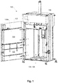
- FIGS 1-3 show a baler 100 for compacting waste such as e.g. cardboard or plastic.
- the baler 100 shown in figures 1-3 is a vertical baler, but the baler 100 could also be a horizontal baler.
- the baler 100 comprises a compaction compartment 104 for containing the waste to be compacted.
- the baler also comprises a door 120 for providing access to the compaction compartment 104.
- the door 120 may therefore be seen as covering an opening 106 to the compaction compartment 104.
- the door 120 may be a one-piece door.
- the door 120 is split into a lower door 122 and an upper door 123 as shown in figures 1-2 .
- the upper 123 and lower door 122 can be opened separately and together.
- the compaction compartment 104 is enclosed by interior walls, the interior walls including a first end wall 124, a second end wall 126, and a number of side walls 128 between the first and second end walls 124, 126.
- the side walls 128 includes a first side wall 128a, a second side wall 128b, a third side wall 128c, and a fourth side wall 128d.
- the first side wall 128a also corresponds to the rear side of the door 120 in the baler 100 shown in figures 1-2 .
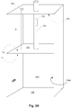
- the interior walls 124, 126, 128b, 128c, 128d are most clearly seen in figure 3A , which shows the baler 100 in a schematic view without the door 102.
- the baler 100 further comprises a frame 102 as shown in figure 1 , which defines the outside surfaces of the baler 100.
- a ram arrangement 108 comprising a press plate 110 configured to move between the first end wall 124 and the second end wall 126 for compacting the waste, and one or more cylinders 116 configured to provide the movement of the press plate 110.
- the ram arrangement 108 is shown in an enhanced view in figure 2 .
- the press plate 110 comprises a detection surface 112 facing the first end wall 124, and a compaction surface 114 facing the second end wall 126 and the waste to be compacted. This is most clearly seen in figures 2-3 .
- the baler also comprises a laser unit 130 configured for measuring a distance D and for providing a first distance parameter 150 representing the measured distance D.
- the laser unit 130 may be positioned in a number of different positions.
- a first position is the one shown in figure 3A , where the laser unit 130 is positioned directly on the first end wall 124.
- the laser unit 130 could be positioned on an arrangement (not shown in figure 3A ) positioned near or on the first end wall 124.
- the distance D is the distance between the laser unit 130 and the detection surface 112 of the press plate 110.
- the laser unit 130 could be positioned near or on the detection surface 112 of the press plate 110. In such configuration, the distance D is the distance between the laser unit 130 and the first end wall 124 or an arrangement positioned near or on the first end wall 124.
- the baler also comprises a sensor 132 configured for providing a pressure output 152 representative of a pressure P with which the press plate 110 compacts the waste inside the compaction compartment 108.
- the sensor 132 can be positioned at a variety of places on the baler 100, which is illustrated by the dotted lines in the box in figure 3A representing the sensor 132.
- a control system 140 comprising a processor 142, a communication interface 144, and a data storage unit 146 is also comprised in the baler 100.
- the data storage unit 146 comprises a program code 148.
- the program code 148 may be used for controlling movement of the ram arrangement 108, for determining when the baler needs to be emptied, for determining when there is flaw on/in the baler, which needs to be addressed, or other matters.
- a multiple of program codes 148 may be present in the control system 140.
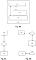
- FIG. 4A shows an overview diagram with some features of a baler 100 including i) the ram arrangement 108 comprising the press plate 110 and one or more cylinders 116 configured to provide the movement of the press plate 110; ii) the laser unit 130 configured for measuring a distance D representing a position of the press plate 110 and for providing a first distance parameter 150 to the control system 140; iii) the sensor 132 configured for providing a pressure output 152 representative of a pressure P with which the press plate 110 compacts the waste inside the compaction compartment 108 to the control system; and iv) the control system 140 comprising the processor 142, the communication interface 144, and the data storage unit 146.
- the baler may comprise a second laser unit 230 where the processor 142 is configured for receiving a second distance parameter 250 from the second laser unit 230.
- the antenna 162 is marked as an optional feature with dotted lines may be part of the baler 100.
- FIG. 4B shows an overview diagram with some features of an external unit 170 including the external device processor 172, the external device communication interface 174, and the external device data storage unit 176.
- the control system 140 of the baler 100 is normally configured for making status data available to an external unit 170 via the communication interface 144.
- the status data comprises one or more of the first distance parameter 150, the pressure output 152, the first comparison 154, the second comparison 156, the chamber full output 158, the distance D, the pre-determined distance parameter Dp, the pressure P, the predetermined pressure parameter Pp, and possibly other parameters.
- external unit 170 may be meant a computer, a tablet, a mobile communication device, such as a smart phone, or similar.
- the location of the external unit 170 may be near the baler or a at physical location far from the baler 100, such as in a different room, building, city, country or even part of the world as long as the external unit communicates with the baler in some manner.
- Figure 3B shows some of the distances inside the compacting chamber including the distance D and Dp. Also, a second pre-determined distance parameter Dp2 is marked in figure 3B along with a marking of the difference between D, Dp and Dp2.
- the distance Dp2 may be defined not as a fixed value but as a value, which is calculated as the function of the measured distance D after each round of compacting of the waste.
- the processor is configured for determining the second pre-determined distance parameter defined as a pre-determined percent value %p smaller than the measured distance after the press plate has compacted the waste.
- the pre-determined percent value %p may e.g. be set 10-20%, such as 15%.
- the press plate may thereby stamp the waste such that a more dense waste bale is obtained. The need for emptying the baler may consequently be postponed as more waste can be compacted before the baler will be considered full.
- the value of Dp may be the same as Dp.
- Dp2 may be smaller or larger than Dp.
- the processor may further be configured for inactivating the movement of the press plate between the second pre-determined distance parameter Dp2 and the second end wall when the second pre-determined distance parameter Dp2 is smaller than the first mentioned pre-determined distance parameter D.
- This inactivation is often relevant if Dp2 is calculated as a function of the measured distance D.
- the inactivation function can limit the movement of press plate when the baler is approaching a situation where it is considered full.
- the external unit 170 may e.g. communicate with the control system 142 of the baler 100 via an external server 168.
- Figures 5A-B show the communication between the baler 100 and the external unit 170, which may be directly ( figure 5A ) or through a server 168 ( figure 5B ).
- the location of the server 162 may be near the baler 100 or the external unit 170, or at a physical location far from the baler 100 and the external unit 170, such as in a different room, building, city, country or even part of the world as long as the server 162 communicates with the baler 100 and the external unit 170 in some manner.
- the communication may be via the internet.
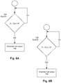
- FIGs 6A-D and 7-8 show different examples of possible program codes 148.
- Figures 6A-D illustrates different processes for determining whether the baler 100 is considered full and should be emptied.
- a chamber full output 158 indicating that the compacting chamber 104 is considered full and should be emptied, is issued.
- the baler 100 is considered full when the first comparison 154 in Test 61 given as D - Dp is at or below zero.
- the baler is considered full when the second comparison 156 in Test 62 given as P - Pp is at or above zero.
- the baler is considered full when both the first comparison 154 in Test 61 is at or below zero and the second comparison 156 in Test 62 is at or above zero.
- the difference between figure 6C and 6D is the order in which the processor performs the tests.
- the two test processes Test 61 and Test 71 could also run in parallel in individual program codes.
- Figure 7 illustrates the process where the processor 142 receives a first and a second distance parameter 150, 250 from the first and second laser unit 130, 230, and determines the first and second distance D, D'.
- the third comparison 160 is made by comparing the difference between the second distance D' and the first distance D in Test 71. If the difference is larger than a pre-determined tilt parameter Tp, the press plate 110 stops the movement towards the second end wall 126. Possibly, the press plate 110 is subsequently moved towards the first end wall 124.
- Figure 8 illustrates the process of comparing the process of monitoring D over time and for generating a malfunction signal if the distance D changes more than predetermined amount Ap in a given time in Test 81. This is illustrated by the comparison of D1 and D2, each representing measures of D at two different times.
Abstract
Description
- The invention relates to a baler comprising a laser unit for measuring a distance indicative of the position of the press plate inside the baler.
- Waste compactors (also known as balers) for compacting waste such as paper, cardboard, cans or the like are well known. These generally comprise a displaceable ram, which is displaceable inside a compaction compartment enclosed by walls in order to compact the waste into bales.
- Both vertically oriented and horizontally oriented balers are present. In the vertical baler, the ram moves in the vertical direction, often from an upper position to a lower position, when compacting the waste. In a horizontal baler, the ram moves in the horizontal direction when compacting the waste. Horizontal balers may comprise opening doors for the waste at one of the sides and/or on the roof part of the baler.
- For determining when a baler is full, a switch system is normally used, in particular for vertically oriented baler, where the switch turns on/off if when the ram/press plate passes the switch positioned inside the compacting compartment.
- Disclosed herein is a baler for compacting waste such as e.g. cardboard or plastic. The baler comprises a compaction compartment for containing the waste to be compacted, the compaction compartment being enclosed by interior walls, the interior walls including a first end wall, a second end wall, and a number of side walls between the first and second end walls.
- The baler also comprises a door for providing access to the compaction compartment, the door covering an opening to the compaction compartment, and a ram arrangement comprising 1) a press plate configured to move between the first end wall and the second end wall for compacting the waste, and 2) one or more cylinders configured to provide the movement of the press plate, wherein the press plate comprises a detection surface facing the first end wall, and a compaction surface facing the second end wall and the waste to be compacted.
- The baler further comprises a laser unit configured for measuring a distance D representing a position of the press plate and for providing a first distance parameter representing the measured distance. The laser unit may be positioned on different positions in the baler, as long as it is possible for the laser unit to provide a measure of the position of the press plate. Such a measure may be the distance from a fixed position to the press plate or from the press plate to a fixed position inside the baler.
- The baler may also comprise a sensor configured for providing a pressure output P representative of a pressure with which the press plate compacts the waste inside the compaction compartment. The sensor may be positioned anywhere on the baler, which will allow it to provide a pressure output representative of the pressure.
- The baler further comprises a control system comprising a processor, a communication interface, and a data storage unit, the data storage unit comprising a program code, wherein the processor is configured for:
- µ receiving the first distance parameter from the laser unit, determining the distance based on the first distance parameter, and making a first comparison comparing the distance (D) to a pre-determined distance parameter (Dp);
- • receiving the pressure output from the sensor, determining the pressure (P) applied to the waste in the compaction chamber based on the pressure output, and making a second comparison by comparing the determined pressure (P) to a pre-determined pressure parameter (Pp);
- • determining whether the compaction compartment is considered to be full based on at least one of the comparisons;
- • providing a chamber full output indicating that the compacting chamber is considered full and should be emptied;
- A baler, which can be monitored and controlled from an external server is thereby provided. In the known balers, a switch is installed inside the compacting compartment. When the press plate activates or deactivates the switch, a signal is provided to the user of the baler informing the user that the baler is full. The switch will be positioned at a specific position inside the baler, which is pre-determined according to a definition of when the baler is full. If the definition of when the baler is full needs to be changed, the switch need to be moved physically to a new position inside the baler. By the baler according to the above, this need is eliminated as the definition of when the baler is full can be changes by changing the pre-determined value(s) for Dp and/or Pp.
- This is not seen before. For example,
US 2013/0319264 A1 shows an example of a compactor, which is used for compacting waste. The compactor may comprise one or more so-called fullness sensors mounted to a side fill door and/or an opening in the top portion of the compactor for detecting when the waste inside the container portion needs to be compacted in order to fill more waste into the compactor. The fullness sensors may also be used in connection with indicating to the user that the compactor is full. However, the compactor does not base a fullness detection on an accurate position of the press plate, nor is the compactor set up for any type of communication with an external unit via the communication interface. - In one or more examples, the first distance parameter is given as a distance provided in a length unit. By length unit is meant metres, centimetres, millimetres, yard, foot, or similar. Alternatively, the first distance parameter may be given as a code, such as bit-value or hex-code; a current or voltage value; or a pulse width modulation (PWM) or frequency value. Independently of which format the laser unit provides the first distance parameter in, this format may be reverted to provide the measure of the distance by the processor receiving the first distance parameter. The choice of format for sending information from the laser unit to the processor may depend on by which means the measure of the distance is send to the processor.
- In one or more examples, the pressure output is given as one or more of a pressure; a hydraulic pressure; a current or voltage value; a code, such as bit-value or hex-code; or PWM or frequency value. Independently of which format the sensor provides the pressure output in, this format may be reverted to provide the measure of the pressure by which the press plate compacts the waste inside the compaction compartment in the processor receiving the pressure output. The choice of format for sending information from the sensor to the processor may depend on by which means the measure of the pressure is send to the processor.
- In one or more examples, the communication interface is making status data available to an external unit via a wireless connection, a wireless local area network WLAN, a cable data network, a radio controlled network, or a mobile network. Other alternatives may also be imagined. By external unit may be meant a computer, a tablet, a mobile communication device, such as a smart phone, or similar. The location of the external unit may be near the baler or a at physical location far from the baler, such as in a different room, building, city, country or even part of the world as long as the external unit communicates with the baler in some manner. The external unit may e.g. communicate with the control system of the baler via an external server.
- The control system may comprise an antenna configured for sending status data from the communication interface directly to the external unit or to the external unit via an external server with which the external unit communicates.
- The location of the server may be near the baler or the external unit, or at a physical location far from the baler and the external unit, such as in a different room, building, city, country or even part of the world as long as the server communicates with the baler and the external unit in some manner. The communication may be via the internet.
- In one or more examples, the external unit is configured for changing the predetermined parameters, by communication directly with the control system of the baler or by communication to the control system via the external server to the control system. In this manner, the user may redefine the parameters defining when a specific baler is considered full from an external location such as e.g. a control centre, a support centre, the suppliers premises or similar. The processor of the baler may be configured for receiving instructions from the external unit and for storing new values for the pre-determined parameters, based on the instructions received from the external unit. Thereby a new value for Dp and/or Pp may be stored in the baler. The need for changing the definition of e.g. when a baler is considered full, may arise if the baler is to be used for compacting a different type of waste with a different density.
- In one or more examples, the control system is configured for moving the press plate towards the second end wall until the measured pressure P is substantially equal to the pre-determined pressure Pp and for subsequently moving the press plate towards the first end wall. The parameter Pp may be the maximum pressure. The maximum pressure may have a value between 150 bar and 250 bar, such as e.g. 200 bar. If the pre-determined pressure is the maximum pressure of the baler, the press plate will have exerted the maximum amount of pressure to the waste, which will then be considered compressed. After the compression, the press plate may return to a start position. The start position will normally be close to the first end wall. If the baler is a vertical baler, the first end wall will be the top of the compacting chamber and the second end wall will be the bottom of the compacting chamber.
- In one or more examples, the first comparison is given as D - Dp, and the second comparison is given as a difference between P - Pp. The predetermined pressure Pp may be the maximum pressure and exceeding this pressure is not possible. If Pp is defined to be close to, but not at, the maximum pressure, which the press plate is able to compact with, situations may occur where P is larger than Pp, i.e. the press plate exerts a pressure onto the waste, which is larger than the predefined value Pp. The compacting chamber may be considered full and should be emptied if, after or during compacting of the waste, the first comparison is at or below zero, and/or the second comparison at or above zero. In some examples, the compacting chamber is considered full only if both the first comparison is at or below zero, and the second comparison is at or above zero.
- In one or more examples, the processor is further configured for sending the chamber full output signal to the external unit when the compacting chamber is considered full. In addition to proving the chamber full output signal to the external unit, a lamp on the baler may also be lit when the baler is full. In addition or as an alternative to the lamp on the baler, a sound signal may be activated when the baler is full. Further, a user may receive a notification when the baler is full or another event is detected, like incorrect movement pattern of the press-plate etc. The notification may be sent via SMS, e-mail, or through custom apps or general communication apps like Twitter, Signal, Messenger, Whatsapp, Telegram, Zoom, Viber, Signal or similar. In this way, the information regarding the full baler may be provided to a multiple platforms and users at the same time.
- In one or more examples, the control system is further configured for inactivating the movement of the press plate towards the first end wall after compacting the waste if the compacting chamber is considered full. By this function, it is prevented that a user can add more waste into the compartment of the baler until the baler has been emptied. The function thus serves as a type of a safety function preventing inappropriate use of the baler. By inactivation is therefore also meant that the press plate does not return to the first end wall after compacting the waste, but instead stays at the position in contact with the compacted waste.
- In one or more examples, the status data further comprises a second predetermined distance parameter Dp2 and a pre-determined stamping parameter Sp, and wherein after the press plate has compacted the waste, the control system is further configured for moving the press plate to a position at the second predetermined distance parameter followed by moving the press plate in the direction of the second end wall a number of times defined by the pre-determined stamping parameter. By this movement, the waste can be compacted further. By number of times is included once, twice, three times, four times, five times, and so forward. The stamping motion may also be seen as a reciprocating motion, also called reciprocation, which is a repetitive up-and-down or back-and-forth linear motion. Two opposite motions that comprise a single reciprocation cycle are referred to as a stroke.
- The distance Dp2 may be defined not as a fixed value but as a value, which is calculated as the function of the measured distance D after each round of compacting of the waste. Thus, in one or more examples, the processor is configured for determining the second pre-determined distance parameter defined as a pre-determined percent value %p smaller than the measured distance after the press plate has compacted the waste. The pre-determined percent value %p may e.g. be set 10-20%, such as 15%. The press plate may thereby stamp the waste such that a more dense waste bale is obtained. The need for emptying the baler may consequently be postponed as more waste can be compacted before the baler will be considered full.
- The processor may further be configured for inactivating the movement of the press plate between the second pre-determined distance parameter Dp2 and the second end wall when the second pre-determined distance parameter Dp2 is smaller than the first mentioned pre-determined distance parameter D. This inactivation is often relevant if Dp2 is calculated as a function of the measured distance D. The inactivation function can limit the movement of press plate when the baler is approaching a situation where it is considered full. The value of Dp may be the same as Dp. Alternatively, Dp2 may be smaller or larger than Dp.
- One or more of the pre-determined parameters may be stored in the data storage unit. Alternatively, the distance pre-determined parameters may be stored in the laser unit and likewise for the pressure related pre-determined parameter. The predetermined parameter(s) will however still be available to the external unit.
- In one or more examples, the control system is further configured for making the second pre-determined distance parameter, the pre-determined percent value, and the pre-determined stamping parameter available to the external unit via the communication interface. The processor, e.g. the data storage unit, of the baler may be configured for receiving instructions from the external unit and for storing new values for the pre-determined parameters, based on the instructions received from the external unit. Thereby the value and/or the function defining the pre-determined parameter(s) can be controlled and altered by a user operating the external unit, e.g. a computer.
- In one or more examples, the baler further comprises a second laser unit configured for measuring a second distance D' representing a second position of the press plate and for providing a second distance parameter representing the measured second distance D'.
- In one or more examples, the baler is a vertical baler. Alternatively, the baler may be a horizontal baler. Normally, the two laser units will be positioned in the same horizontal plane in a vertical baler and the same vertical plane in a horizontal baler.
- Additional laser units may also be imagined. In one or more examples, the laser unit(s), are positioned directly on the first end wall or on an arrangement positioned near or on the first end wall. An arrangement near the first end wall also includes a part of a side wall close to the first end wall or an arrangement on this side wall part close to the first end wall.
- In one or more examples, the laser unit(s), are positioned on the detection surface of the press plate. The laser units may be positioned far apart from each other on or near the first end wall. Alternatively, the laser units may be positioned on different side walls opposite each other.
- In one or more examples, the distance(s) measured by the laser unit(s) are measured by means of time-of-flight measurements. By time-of-flight (ToF) is meant the measurement of the time taken a light wave to travel a distance through a medium. This information may then be used to establish a time standard (such as an atomic fountain), as a way to measure velocity or path length. The traveling light may be detected indirectly, e.g., by light scattered from a surface.
- The processor may further be configured for receiving the second distance parameter from the second laser unit, determining the second distance based on the second distance parameter, comparing the second distance to the first mentioned distance and determining a third comparison as the difference between the second distance and the first mentioned distance. If the third comparison is larger than a pre-determined tilt parameter, the processor may be configured for stopping the movement of the press plate towards the second end wall, and possibly moving the press plate towards the first end wall. This function ensures that if the press plate is not moving forward symmetrically, but instead in a tilted manner, the press plate movement is stopped. As the baler is normally designed such that the press plate compacts the waste evenly over the surface of the press plate. If the press plate is tilted, it will not compact the waste evenly. Furthermore, a tilted movement of the press plate will add a strain on the baler as the press plate will push against the inner walls of the compacting chamber.
- Any of the laser units may be configured for measuring the distance continuously or at a pre-determined interval, and wherein the processor is configured for monitoring changes between the distance over time. In this manner a complete overview of the movement of the press plate can be obtained, e.g. on the external unit.
- In one or more examples, when the baler is not compacting waste, the processor is configured for generating a malfunction signal if the distance changes more than pre-determined amount, such as e.g. 5%. Thus, if the baler is not actively compacting waste, but instead in a waiting position, e.g. during off work hours, the press plate should not be moving. If a change in the measured distance(s) D or D' are detected, it is an indication of a malfunction in the press plate. If the press plate is positioned at a top position in a vertical baler, and the press plate drops in height over time when the ram is supposed to be at the same top level, there is normally a malfunction in the cylinders, valves or hoses, e.g. there is a leak or similar. Like, if the press plate is resting on the compacted waste, and the compacted waste is able to push the press plate upwards in a vertical baler when the ram is supposed to be resting in the same position on top of the waste, there is something wrong with the cylinders, valves or hoses.
- In one or more examples, the processor is configured for determining a speed at which the distance changes over time after the ram arrangement has compacted the waste. This applies to both laser unit if more than one laser unit is present in the baler. The speed is normally calculated as the difference in distance divided by the time, which it takes the press plate to move that distance. The speed may provide information on the elasticity of the waste and thereby give an indication of which type of waste the baler has compacted, since the speed is a reflection of how much the waste material pushes the press plate towards the first end wall after compaction of the waste. Thus, the measure of distance between the laser unit and the press plate (or first end wall depending on the positioning of the laser unit) can provide a user with the external unit information on what kind of the material, a specific baler has compacted. Based on this type of information, the pre-determined parameters may require an adjustment, which can be handled through the external unit communicating with the baler.
- In one or more examples, the laser unit(s) are positioned close to or on the first end wall, wherein the distance is the distance(s) between the laser unit(s) and the detection surface of the press plate.
- In one or more alternative examples, the laser unit(s) are positioned near or on the detection surface of the press plate, wherein the distance(s) are the distance between the laser unit(s) and the first end wall or an arrangement positioned near or on the first end wall.
- By the detection surface of the press plate is also included a surface of an item positioned near or on the press plate detection surface.
- By "positioned close to or on the first end wall" is included that the laser unit is positioned directly on the first end wall; on an arrangement, e.g. a bracket arrangement positioned near or on the first end wall; directly on a part of one of the side walls close to the first end wall, or on an arrangement, e.g. a bracket arrangement on the side wall.
- In one or more examples, the laser unit(s) are positioned on a non-movable part between the first end wall and the press plate, wherein the distance(s) are the distance between the laser unit(s) and the detection surface of the press plate. Examples of non-movable parts include the first end wall and a bracket arrangement positioned on the first end wall or one of the side walls.
- In one or more examples, when the ram arrangement is at the first end wall, the processor is configured for determining the amount of waste in the baler based on a comparison between the distance D and a maximum distance Dmax corresponding to an empty compacting compartment. This functionality may be used as a check that the baler has been (completely) emptied at times where it should have been. Further, information on how many days it takes on average between each time the baler is considered emptied may be used for calculating the capacity needed at the site where the baler is positioned and/or the size of the baler needed in the future. Also an estimate of when the baler most likely will need to be emptied the next time may be obtained. This is helpful for planning.
- In one or more examples, the baler comprises one or two cylinders. The one or more cylinders may be actuators, such as hydraulic actuators, pneumatic actuators, electric actuators, electrohydraulic actuators, or coiled actuators.
- By hydraulic actuator is meant a cylinder that uses hydraulic power to facilitate a mechanical operation. The hydraulic cylinder may consists of a hollow cylindrical tube along which a piston can slide. If the piston is a single piston, it normally only moves in one direction. A spring is therefore being frequently used to give the piston a return stroke. If the piston is a double piston, pressure is applied on each side of the piston and any difference in pressure between the two sides of the piston can move the piston in either of the two directions.
- By pneumatic actuators is meant an actuator, which converts energy formed by vacuum or compressed air at high pressure into either linear or rotary motion.
- By electric actuator is meant an actuator, which may be used to power a motor that converts electrical energy into mechanical torque.
- By electrohydraulic actuator is meant an actuator where an electric motor remains the prime mover, but provides torque to operate a hydraulic accumulator that is then used to transmit actuation force.
- By coiled actuator is meant a cylinder with an inner threaded surface, where a threaded rod inside the cylinder moves the cylinder forward or backward by a rotational motion of the rod. Included in the term coiled actuator is also a twisted and coiled polymer actuator, which may also be referred to as a supercoiled polymer actuator. The supercoiled polymer actuator is a coiled polymer that can be actuated by electric power.
- The baler according to any preceding item, wherein the door comprises a main door and a secondary door. The secondary door may open along with opening of the main door and may open individually. The secondary door is often the door through which provides access to the user for loading waste into the compacting chamber. In that manner, the secondary door may be comprises in the main door. The main door may comprises a frame part in which the secondary door is position. Thus, the secondary door may be a door positioned in the main door. The secondary door may be hinged to a frame in the main door. The hinged arrangement may be in the vertical plane or in the horizontal plane. The secondary door may be referred to as a filling door or a flap door depending on the hinged arrangements position.
- In one or more examples, the door comprises a lower door and an upper door. The main door is normally referred to as the lower door in this setup and the upper door is the secondary door. The lower door is normally closed when the user puts waste into baler through the upper door, which can be opened separately from the lower door. When the baler needs to be emptied, the two-door part open together.
- The combined door often opens outwards with one side hinged to the baler frame, whereby the bale can be removed from the baler.
- In a vertical baler, the upper door may be able to slide up and down for providing access to the user for loading waste into the compacting chamber.
- Disclosed herein is also a method for accessing the processor in a baler according to the above, wherein the method comprises:
- ∘ providing a baler;
- ∘ providing an external unit comprising an external device processor, an external device communication interface, and an external device data storage unit;
- ∘ providing an external unit comprising an external device processor, an external device communication interface, and an external device data storage unit;
- ∘ obtaining status data from the control system of the baler;
- ∘ changing one or more of the pre-determined parameters (Dp, Pp, Tp) in the data storage unit in the control system of the baler externally via the external unit.
- Various examples are described hereinafter with reference to the figures. Like reference numerals refer to like elements throughout. Like elements will, thus, not be described in detail with respect to the description of each figure. It should also be noted that the figures are only intended to facilitate the description of the examples. They are not intended as an exhaustive description of the claimed invention or as a limitation on the scope of the claimed invention. In addition, an illustrated example needs not have all the aspects or advantages shown. An aspect or an advantage described in conjunction with a particular example is not necessarily limited to that example and can be practiced in any other examples even if not so illustrated, or if not so explicitly described.
-
Figure 1 shows a baler with an open door. -
Figure 2 shows a close-up of the baler infigure 1 . -
Figure 3A shows a schematic view of a baler, andfigure 3AB illustrates some distances inside the baler. -
Figure 4A shows an overview diagram with some features of a baler,figure 4B an overview diagram with some features of an external unit. -
Figures 5A-B show the communication between the baler and the external unit. -
Figures 6-8 show flow diagrams illustrating examples of processes in the balers control system. - Exemplary examples will now be described more fully hereinafter with reference to the accompanying drawings. In this regard, the present examples may have different forms and should not be construed as being limited to the descriptions set forth herein. Accordingly, the examples are merely described below, by referring to the figures, to explain aspects. As used herein, the term "and/or" includes any and all combinations of one or more of the associated listed items. Expressions such as "at least one of," when preceding a list of elements, modify the entire list of elements and do not modify the individual elements of the list.
- In the drawings, thicknesses of a plurality of layers and areas are illustrated in an enlarged manner for clarity and ease of description thereof. When a layer, area, element, or plate is referred to as being "on" another layer, area, element, or plate, it may be directly on the other layer, area, element, or plate, or intervening layers, areas, elements, or plates may be present therebetween. Conversely, when a layer, area, element, or plate is referred to as being "directly on" another layer, area, element, or plate, there are no intervening layers, areas, elements, or plates therebetween. Further when a layer, area, element, or plate is referred to as being "below" another layer, area, element, or plate, it may be directly below the other layer, area, element, or plate, or intervening layers, areas, elements, or plates may be present therebetween. Conversely, when a layer, area, element, or plate is referred to as being "directly below" another layer, area, element, or plate, there are no intervening layers, areas, elements, or plates therebetween.
- The spatially relative terms "lower" or "bottom" and "upper" or "top", "below", "beneath", "less", "above", and the like, may be used herein for ease of description to describe the relationship between one element or component and another element or component as illustrated in the drawings. It will be understood that the spatially relative terms are intended to encompass different orientations of the device in use or operation, in addition to the orientation depicted in the drawings. For example, in the case where a device illustrated in the drawings is turned over, elements described as being on the "lower" side of other elements, or "below" or "beneath" another element would then be oriented on "upper" sides of the other elements, or "above" another element. Accordingly, the illustrative term "below" or "beneath" may include both the "lower" and "upper" orientation positions, depending on the particular orientation of the figure. Similarly, if the device in one of the figures is turned over, elements described as "below" or "beneath" other elements would then be oriented "above" the other elements. The exemplary terms "below" or "beneath" can, therefore, encompass both an orientation of above and below, and thus the spatially relative terms may be interpreted differently depending on the orientations described.
- Throughout the specification, when an element is referred to as being "connected" to another element, the element is "directly connected" to the other element, or "electrically connected" to the other element with one or more intervening elements interposed therebetween.
- The terminology used herein is for the purpose of describing particular examples only and is not intended to be limiting. As used herein, the singular forms "a," "an," and "the" are intended to include the plural forms, including "at least one," unless the content clearly indicates otherwise. "At least one" is not to be construed as limiting "a" or "an." It will be further understood that the terms "comprises," "comprising," "includes" and/or "including," when used in this specification, specify the presence of stated features, integers, steps, operations, elements, and/or components, but do not preclude the presence or addition of one or more other features, integers, steps, operations, elements, components, and/or groups thereof.
- It will be understood that, although the terms "first," "second," "third," and the like may be used herein to describe various elements, these elements should not be limited by these terms. These terms are only used to distinguish one element from another element. Thus, "a first element" discussed below could be termed "a second element" or "a third element," and "a second element" and "a third element" may be termed likewise without departing from the teachings herein.
- "About" or "approximately" as used herein is inclusive of the stated value and means within an acceptable range of deviation for the particular value as determined by one of ordinary skill in the art, considering the measurement in question and the error associated with measurement of the particular quantity (i.e., the limitations of the measurement system). For example, "about" may mean within one or more standard deviations, or within ± 30%, 20%, 10%, 5% of the stated value.
- Unless otherwise defined, all terms used herein (including technical and scientific terms) have the same meaning as commonly understood by those skilled in the art to which this invention pertains. It will be further understood that terms, such as those defined in commonly used dictionaries, should be interpreted as having a meaning that is consistent with their meaning in the context of the relevant art and will not be interpreted in an idealized or overly formal sense unless expressly so defined in the present specification.
- Exemplary examples are described herein with reference to cross section illustrations that are schematic illustrations of idealized examples, wherein like reference numerals refer to like elements throughout the specification. As such, variations from the shapes of the illustrations as a result, for example, of manufacturing techniques and/or tolerances, are to be expected. Thus, examples described herein should not be construed as limited to the particular shapes of regions as illustrated herein but are to include deviations in shapes that result, for example, from manufacturing. For example, a region illustrated or described as flat may have rough and/or nonlinear features. Moreover, sharp angles that are illustrated may be rounded. Thus, the regions illustrated in the figures are schematic in nature and their shapes are not intended to illustrate the precise shape of a region and are not intended to limit the scope of the present claims. Some of the parts which are not associated with the description may not be provided in order to specifically describe exemplary examples of the present disclosure.
-
Figures 1-3 show abaler 100 for compacting waste such as e.g. cardboard or plastic. Thebaler 100 shown infigures 1-3 is a vertical baler, but thebaler 100 could also be a horizontal baler. Thebaler 100 comprises acompaction compartment 104 for containing the waste to be compacted. The baler also comprises adoor 120 for providing access to thecompaction compartment 104. Thedoor 120 may therefore be seen as covering an opening 106 to thecompaction compartment 104. Thedoor 120 may be a one-piece door. Alternatively, thedoor 120 is split into alower door 122 and anupper door 123 as shown infigures 1-2 . The upper 123 andlower door 122 can be opened separately and together. - The
compaction compartment 104 is enclosed by interior walls, the interior walls including afirst end wall 124, asecond end wall 126, and a number of side walls 128 between the first andsecond end walls first side wall 128a, asecond side wall 128b, athird side wall 128c, and afourth side wall 128d. Thefirst side wall 128a also corresponds to the rear side of thedoor 120 in thebaler 100 shown infigures 1-2 . Theinterior walls figure 3A , which shows thebaler 100 in a schematic view without thedoor 102. - The
baler 100 further comprises aframe 102 as shown infigure 1 , which defines the outside surfaces of thebaler 100. Inside thebaler 100 is aram arrangement 108 comprising apress plate 110 configured to move between thefirst end wall 124 and thesecond end wall 126 for compacting the waste, and one ormore cylinders 116 configured to provide the movement of thepress plate 110. Theram arrangement 108 is shown in an enhanced view infigure 2 . Thepress plate 110 comprises adetection surface 112 facing thefirst end wall 124, and acompaction surface 114 facing thesecond end wall 126 and the waste to be compacted. This is most clearly seen infigures 2-3 . - As shown in
figure 3A , the baler also comprises alaser unit 130 configured for measuring a distance D and for providing afirst distance parameter 150 representing the measured distance D. Thelaser unit 130 may be positioned in a number of different positions. A first position is the one shown infigure 3A , where thelaser unit 130 is positioned directly on thefirst end wall 124. Alternatively, thelaser unit 130 could be positioned on an arrangement (not shown infigure 3A ) positioned near or on thefirst end wall 124. In both cases, the distance D is the distance between thelaser unit 130 and thedetection surface 112 of thepress plate 110. Yet alternatively, thelaser unit 130 could be positioned near or on thedetection surface 112 of thepress plate 110. In such configuration, the distance D is the distance between thelaser unit 130 and thefirst end wall 124 or an arrangement positioned near or on thefirst end wall 124. - The baler also comprises a
sensor 132 configured for providing apressure output 152 representative of a pressure P with which thepress plate 110 compacts the waste inside thecompaction compartment 108. Thesensor 132 can be positioned at a variety of places on thebaler 100, which is illustrated by the dotted lines in the box infigure 3A representing thesensor 132. - A
control system 140 comprising aprocessor 142, acommunication interface 144, and adata storage unit 146 is also comprised in thebaler 100. Thedata storage unit 146 comprises a program code 148. The program code 148 may be used for controlling movement of theram arrangement 108, for determining when the baler needs to be emptied, for determining when there is flaw on/in the baler, which needs to be addressed, or other matters. A multiple of program codes 148 may be present in thecontrol system 140. -
Figure 4A shows an overview diagram with some features of abaler 100 including i) theram arrangement 108 comprising thepress plate 110 and one ormore cylinders 116 configured to provide the movement of thepress plate 110; ii) thelaser unit 130 configured for measuring a distance D representing a position of thepress plate 110 and for providing afirst distance parameter 150 to thecontrol system 140; iii) thesensor 132 configured for providing apressure output 152 representative of a pressure P with which thepress plate 110 compacts the waste inside thecompaction compartment 108 to the control system; and iv) thecontrol system 140 comprising theprocessor 142, thecommunication interface 144, and thedata storage unit 146. Optionally, marked by the dotted lines, the baler may comprise asecond laser unit 230 where theprocessor 142 is configured for receiving asecond distance parameter 250 from thesecond laser unit 230. Also, theantenna 162 is marked as an optional feature with dotted lines may be part of thebaler 100. -
Figure 4B shows an overview diagram with some features of anexternal unit 170 including theexternal device processor 172, the externaldevice communication interface 174, and the external devicedata storage unit 176. Thecontrol system 140 of thebaler 100 is normally configured for making status data available to anexternal unit 170 via thecommunication interface 144. The status data comprises one or more of thefirst distance parameter 150, thepressure output 152, thefirst comparison 154, thesecond comparison 156, the chamberfull output 158, the distance D, the pre-determined distance parameter Dp, the pressure P, the predetermined pressure parameter Pp, and possibly other parameters. - By
external unit 170 may be meant a computer, a tablet, a mobile communication device, such as a smart phone, or similar. The location of theexternal unit 170 may be near the baler or a at physical location far from thebaler 100, such as in a different room, building, city, country or even part of the world as long as the external unit communicates with the baler in some manner. -
Figure 3B shows some of the distances inside the compacting chamber including the distance D and Dp. Also, a second pre-determined distance parameter Dp2 is marked infigure 3B along with a marking of the difference between D, Dp and Dp2. - The distance Dp2 may be defined not as a fixed value but as a value, which is calculated as the function of the measured distance D after each round of compacting of the waste. Thus, in one or more examples, the processor is configured for determining the second pre-determined distance parameter defined as a pre-determined percent value %p smaller than the measured distance after the press plate has compacted the waste. The pre-determined percent value %p may e.g. be set 10-20%, such as 15%. The press plate may thereby stamp the waste such that a more dense waste bale is obtained. The need for emptying the baler may consequently be postponed as more waste can be compacted before the baler will be considered full. The value of Dp may be the same as Dp. Alternatively, Dp2 may be smaller or larger than Dp.
- The processor may further be configured for inactivating the movement of the press plate between the second pre-determined distance parameter Dp2 and the second end wall when the second pre-determined distance parameter Dp2 is smaller than the first mentioned pre-determined distance parameter D. This inactivation is often relevant if Dp2 is calculated as a function of the measured distance D. The inactivation function can limit the movement of press plate when the baler is approaching a situation where it is considered full.
- The
external unit 170 may e.g. communicate with thecontrol system 142 of thebaler 100 via anexternal server 168.Figures 5A-B show the communication between thebaler 100 and theexternal unit 170, which may be directly (figure 5A ) or through a server 168 (figure 5B ). The location of theserver 162 may be near thebaler 100 or theexternal unit 170, or at a physical location far from thebaler 100 and theexternal unit 170, such as in a different room, building, city, country or even part of the world as long as theserver 162 communicates with thebaler 100 and theexternal unit 170 in some manner. The communication may be via the internet. -
Figures 6A-D and7-8 show different examples of possible program codes 148.Figures 6A-D illustrates different processes for determining whether thebaler 100 is considered full and should be emptied. When thebaler 100 is considered full, a chamberfull output 158, indicating that the compactingchamber 104 is considered full and should be emptied, is issued. Infigure 6A , thebaler 100 is considered full when thefirst comparison 154 inTest 61 given as D - Dp is at or below zero. Infigure 6B , the baler is considered full when thesecond comparison 156 inTest 62 given as P - Pp is at or above zero. Infigures 6C-D , the baler is considered full when both thefirst comparison 154 inTest 61 is at or below zero and thesecond comparison 156 inTest 62 is at or above zero. The difference betweenfigure 6C and 6D is the order in which the processor performs the tests. The twotest processes Test 61 andTest 71 could also run in parallel in individual program codes. -
Figure 7 illustrates the process where theprocessor 142 receives a first and asecond distance parameter second laser unit third comparison 160 is made by comparing the difference between the second distance D' and the first distance D inTest 71. If the difference is larger than a pre-determined tilt parameter Tp, thepress plate 110 stops the movement towards thesecond end wall 126. Possibly, thepress plate 110 is subsequently moved towards thefirst end wall 124. -
Figure 8 illustrates the process of comparing the process of monitoring D over time and for generating a malfunction signal if the distance D changes more than predetermined amount Ap in a given time inTest 81. This is illustrated by the comparison of D1 and D2, each representing measures of D at two different times. - The invention is further described in the following items supporting the description of the invention.
- 1. A baler (100) for compacting waste such as e.g. cardboard or plastic, the baler (100) comprising:
- a compaction compartment (104) for containing the waste to be compacted, the compaction compartment (104) being enclosed by interior walls, the interior walls including a first end wall (124), a second end wall (126), and a number of side walls (128) between the first and second end walls (124, 126);
- a door (120) for providing access to the compaction compartment (104), the door (120) covering an opening (106) to the compaction compartment (104);
- a ram arrangement (108) comprising:
- ∘ a press plate (110) configured to move between the first end wall (124) and the second end wall (126) for compacting the waste;
- ∘ one or more cylinders (116) configured to provide the movement of the press plate (110);
- a laser unit (130) configured for measuring a distance (D) representing a position of the press plate (110) and for providing a first distance parameter (150) representing the measured distance (D);
- a sensor (132) configured for providing a pressure output (152) representative of a pressure (P) with which the press plate (110) compacts the waste inside the compaction compartment (108);
- a control system (140) comprising a processor (142), a communication interface (144), and a data storage unit (146), the data storage unit (146) comprising a program code (148);
- ∘ receiving the first distance parameter (150) from the laser unit (130), determining the distance (D) based on the first distance parameter (150), and making a first comparison (154) comparing the distance (D) to a pre-determined distance parameter (Dp);
- ∘ receiving the pressure output (152) from the sensor (132), determining the pressure (P) applied to the waste in the compaction chamber (104) based on the pressure output (152), and making a second comparison (156) by comparing the determined pressure (P) to a pre-determined pressure parameter (Pp);
- ∘ determining whether the compaction compartment (104) is considered to be full based on at least one of the comparisons (154, 156);
- ∘ providing a chamber full output (158) indicating that the compacting chamber (104) is considered full and should be emptied;
- 2. The baler according to any preceding item, wherein the first distance parameter (150) is given as one or more of a distance provided in a length unit; a code, such as bit-value or hex-code; a current or voltage value; or PWM or frequency value.
- 3. The baler according to any preceding item, wherein the pressure output (152) is given as one or more of a pressure; a hydraulic pressure; a current or voltage value; a code, such as bit-value or hex-code; or PWM or frequency value.
- 4. The baler according to any preceding item, wherein the communication interface (144) is making status data available to an external unit (170) via a wireless connection, a wireless local area network (WLAN), a cable data network, a radio controlled network, or a mobile network.
- 5. The baler according to any preceding item, wherein the control system (140) comprises an antenna (166) configured for sending status data from the communication interface (144) directly to the external unit (170) or to the external unit (170) via an external server (168) with which the external unit (170) communicates.
- 6. The baler according to any preceding item, wherein the external unit (170) is configured for changing the pre-determined parameters (Dp, Pp) by communication directly with the control system (140) of the baler or by communication to the control system (140) via the external server (168) to the control system (140), and wherein the processor (142) of the baler (100) is configured for receiving instructions from the external unit (170) and for storing new values for the pre-determined parameters (Dp, Pp) based on the instructions received from the external unit (170).
- 7. The baler according to any preceding item, wherein the control system (140) is configured for moving the press plate (110) towards the second end wall (126) until the measured pressure (P) is substantially equal to the pre-determined pressure (Pp) and for subsequently moving the press plate towards the first end wall (124).
- 8. The baler according to any preceding item, wherein the first comparison (154) is given as D - Dp, and the second comparison (156) is given as a difference between P - Pp, and wherein the compacting chamber (104) is considered full and should be emptied if, after or during compacting of the waste, the first comparison (154) is at or below zero, and/or the second comparison (156) at or above zero.
- 9. The baler according to item 8, wherein the compacting chamber (104) is considered full only if both the first comparison (154) is at or below zero, and the second comparison (156) is at or above zero.
- 10. The baler according to any of the items 8-9, wherein the processor (142) is further configured for sending the chamber full output (158) signal to the external unit (170) when the compacting chamber (104) is considered full.
- 11. The baler according to any of the items 8-10, wherein the control system (140) is further configured for inactivating the movement of the press plate (110) towards the first end wall (124) after compacting the waste if the compacting chamber (104) is considered full.
- 12. The baler according to any preceding item, wherein the status data further comprises a second pre-determined distance parameter (Dp2) and a predetermined stamping parameter (Sp), and wherein after the press plate (110) has compacted the waste, the control system (140) is further configured for moving the press plate (110) to a position at the second pre-determined distance parameter (Dp2) followed by moving the press plate (100) in the direction of the second end wall (126) a number of times defined by the predetermined stamping parameter (Sp).
- 13. The baler according to item 12, wherein the processor (142) is configured for determining the second pre-determined distance parameter (Dp2) defined as a pre-determined percent value (%p) smaller than the measured distance (D) after the press plate (110) has compacted the waste, wherein the predetermined percent value (%p) is 10-20%, such as 15%.
- 14. The baler according to any of the items 12-13, wherein the processor (142) is configured for inactivating the movement of the press plate (110) between the second pre-determined distance parameter (Dp2) and the second end wall (126) when the second pre-determined distance parameter (Dp2) is smaller than the first mentioned pre-determined distance parameter (Dp).
- 15. The baler according to any preceding item, wherein one or more of the predetermined parameters (Dp, Pp, Sp, Dp2) are stored in the data storage unit (146).
- 16. The baler according to item 15, wherein the control system (140) is further configured for making the second pre-determined distance parameter (Dp2), the pre-determined percent value (%p), and the pre-determined stamping parameter (Sp) available to the external unit (170) via the communication interface (144), and wherein the data storage unit (146) of the baler (100) is configured for receiving instructions from the external unit (170) and for storing new values for the pre-determined parameters (Dp2, Sp) based on the instructions received from the external unit (170).
- 17. The baler according to any preceding item, wherein the baler (100) further comprises a second laser unit (230) configured for measuring a second distance (D') representing a second position of the press plate (110) and for providing a second distance parameter (250) representing the measured second distance (D').
- 18. The baler according to item 17, wherein the processor (142) is further configured for:
- receiving the second distance parameter (250) from the second laser unit (230), determining the second distance (D') based on the second distance parameter (250), comparing the second distance (D') to the first mentioned distance (D), and determining a third comparison (160) as the difference between the second distance (D') and the first mentioned distance (D);
- stopping the movement of the press plate (110) towards the second end wall (126), and possibly moving the press plate (110) towards the first end wall (124), if the third comparison (160) is larger than a predetermined tilt parameter (Tp).
- 19. The baler according to any preceding item, wherein the laser unit (130) is configured for measuring the distance (D) continuously or at a pre-determined interval (tp), and wherein the processor (142) is configured for monitoring changes between the distance (D) over time.
- 20. The baler according to item 19, wherein when the baler (100) is not compacting waste, the processor (142) is configured for generating a malfunction signal if the distance (D) changes more than pre-determined amount, such as e.g. 5%.
- 21. The baler according to any of the items 19-20, wherein the processor (142) is configured for determining a speed at which the distance (D) changes over time after the ram arrangement (108) has compacted the waste.
- 22. The baler according to any preceding item, wherein when the ram arrangement (108) is at the first end wall (124), the processor (142) is configured for determining the amount of waste in the baler (100) based on a comparison between the distance (D) and a maximum distance (Dmax) corresponding to an empty compacting compartment (104).
- 23. The baler according to any preceding item, wherein the baler (100) is a vertical baler.
- 24. The baler according to any preceding item, wherein the laser unit(s) (130, 230) are positioned:
- ∘ close to or on the first end wall (124), wherein the distance(s) (D, D') are the distance between the laser unit(s) (130, 230) and the detection surface (112) of the press plate (110); or
- ∘ near or on the detection surface (112) of the press plate (110), wherein the distance(s) (D, D') are the distance between the laser unit(s) (130, 230) and the first end wall (124) or an arrangement positioned near or on the first end wall (124).
- 25. The baler according to any preceding item, wherein the laser unit(s) (130, 230) are positioned on a non-movable part between the first end wall (124) and the press plate (110), wherein the distance(s) (D, D') are the distance between the laser unit(s) (130, 230) and the detection surface (112) of the press plate (110).
- 26. The baler according to any preceding item, wherein the laser unit(s) (130, 230) are positioned directly on the first end wall (124) or on an arrangement positioned near or on the first end wall (124).
- 27. The baler according to any of the items 1-24, wherein the laser unit(s) (130, 230) are positioned on the detection surface (112) of the press plate (110.)
- 28. The baler according to any preceding item, wherein the distance(s) (D, D') measured by the laser unit(s) are measured by means of time-of-flight measurements.
- 29. The baler according to any preceding item, wherein the baler comprises one or two cylinders (116).
- 30. The baler according to any preceding item, wherein the one or more cylinders (116) are actuators, such as hydraulic actuators, pneumatic actuators, electric actuators, electrohydraulic actuators, or coiled actuators.
- 31. The baler according to any preceding item, wherein the door (120) comprises a main door and a secondary door.
- 32. The baler according to item 31, wherein the secondary door is comprises in the main door.
- 33. The baler according to any preceding item, wherein the door (120) comprises a lower door (122) and an upper door (123).
- 34. A method for accessing the processor (142) in a baler (100) according to any of the items 1-33, wherein the method comprises:
- ∘ providing a baler (100) according to any of the items 1-33;
- ∘ providing an external unit (170) comprising an external device processor (172), an external device communication interface (174), and an external device data storage unit (176);
- ∘ obtaining status data from the control system (140) of the baler (100);
- ∘ changing one or more of the pre-determined parameters (Dp, Pp, Tp) in the data storage unit (146) in the control system (140) of the baler (100) externally via the external unit (170).
- 35. A method according to item 34, wherein the external unit (170) is a computer, a tablet, a mobile communication device, such as a smart phone, or similar.
- 36. A method according to item 34 or 35, wherein the external unit (170) communicates with the control system (140) of the baler (100) via an external server (168).
-
- 100
- baler
- 102
- frame
- 104
- compaction compartment for containing waste
- 106
- opening to the compaction compartment
- 108
- ram arrangement
- 110
- press plate
- 112
- detection surface of the press plate
- 114
- compartment-facing surface of the press plate
- 116
- cylinder
- 120
- door for providing access to the compaction compartment
- 122
- lower door
- 123
- upper door
- 124
- first end wall
- 126
- second end wall
- 128
- side wall
- 128a
- first side wall
- 128b
- second side wall
- 128c
- third side wall
- 128d
- fourth side wall
- 130
- first laser unit
- 132
- sensor
- 140
- control system
- 142
- processor
- 144
- communication interface
- 146
- data storage unit
- 148
- program code
- 150
- first distance parameter
- 152
- pressure output
- 154
- comparison between D and Dp
- 156
- comparison between P and Pp
- 158
- chamber full output
- 160
- comparison between D and D'
- 166
- antenna
- 168
- external server
- 170
- external device
- 172
- external device processor
- 174
- external device communication interface
- 176
- external device data storage unit
- 230
- second laser unit
- 250
- second distance parameter
- D
- distance
- D1
- distance at a first time
- D2
- distance at a second time
- D'
- second distance
- Dmax
- maximum distance
- Dp
- pre-determined distance parameter
- Dp2
- second pre-determined distance parameter
- Sp
- pre-determined stamping parameter
- P
- pressure with which the press plate compacts the waste
- Pp
- pre-determined pressure parameter
- Tp
- pre-determined tilt parameter
- Ap
- pre-determined amount
Claims (15)
- A baler (100) for compacting waste such as e.g. cardboard or plastic, the baler (100) comprising:- a compaction compartment (104) for containing the waste to be compacted, the compaction compartment (104) being enclosed by interior walls, the interior walls including a first end wall (124), a second end wall (126), and a number of side walls (128) between the first and second end walls (124, 126);- a door (120) for providing access to the compaction compartment (104), the door (120) covering an opening (106) to the compaction compartment (104);- a ram arrangement (108) comprising:∘ a press plate (110) configured to move between the first end wall (124) and the second end wall (126) for compacting the waste;∘ one or more cylinders (116) configured to provide the movement of the press plate (110);wherein the press plate (110) comprises a detection surface (112) facing the first end wall (124), and a compaction surface (114) facing the second end wall (126) and the waste to be compacted;- a laser unit (130) configured for measuring a distance (D) representing a position of the press plate (110) and for providing a first distance parameter (150) representing the measured distance (D);- a sensor (132) configured for providing a pressure output (152) representative of a pressure (P) with which the press plate (110) compacts the waste inside the compaction compartment (108);- a control system (140) comprising a processor (142), a communication interface (144), and a data storage unit (146), the data storage unit (146) comprising a program code (148);wherein the processor (142) is configured for:∘ receiving the first distance parameter (150) from the laser unit (130), determining the distance (D) based on the first distance parameter (150), and making a first comparison (154) comparing the distance (D) to a pre-determined distance parameter (Dp);∘ receiving the pressure output (152) from the sensor (132), determining the pressure (P) applied to the waste in the compaction chamber (104) based on the pressure output (152), and making a second comparison (156) by comparing the determined pressure (P) to a pre-determined pressure parameter (Pp);∘ determining whether the compaction compartment (104) is considered to be full based on at least one of the comparisons (154, 156);∘ providing a chamber full output (158) indicating that the compacting chamber (104) is considered full and should be emptied;wherein the control system (140) is further configured for making status data available to an external unit (170) via the communication interface (144), wherein the status data comprises one or more of the first distance parameter (150), the pressure output (152), the first comparison (154), the second comparison (156), the chamber full output (158), the distance (D), the predetermined distance parameter (Dp), the pressure (P), and the pre-determined pressure parameter (Pp).
- The baler according to any preceding claim, wherein• the first distance parameter (150) is given as one or more of a distance provided in a length unit; a code, such as bit-value or hex-code; a current or voltage value; or PWM or frequency value and/or• the pressure output (152) is given as one or more of a pressure; a hydraulic pressure; a current or voltage value; a code, such as bit-value or hex-code; or PWM or frequency value.
- The baler according to any preceding claim, wherein the communication interface (144) is making status data available to an external unit (170) via a wireless connection, a wireless local area network (WLAN), a cable data network, a radio controlled network, or a mobile network, and
wherein the control system (140) possibly comprises an antenna (166) configured for sending status data from the communication interface (144) directly to the external unit (170) or to the external unit (170) via an external server (168) with which the external unit (170) communicates. - The baler according to any preceding claim, wherein the external unit (170) is configured for changing the pre-determined parameters (Dp, Pp) by communication directly with the control system (140) of the baler or by communication to the control system (140) via the external server (168) to the control system (140), and wherein the processor (142) of the baler (100) is configured for receiving instructions from the external unit (170) and for storing new values for the pre-determined parameters (Dp, Pp) based on the instructions received from the external unit (170).
- The baler according to any preceding claim, wherein the first comparison (154) is given as D - Dp, and the second comparison (156) is given as a difference between P - Pp, and wherein the compacting chamber (104) is considered full and should be emptied if, after or during compacting of the waste, the first comparison (154) is at or below zero, and/or the second comparison (156) at or above zero.
- The baler according to any preceding claim, wherein the status data further comprises a second pre-determined distance parameter (Dp2) and a predetermined stamping parameter (Sp), and wherein after the press plate (110) has compacted the waste, the control system (140) is further configured for moving the press plate (110) to a position at the second pre-determined distance parameter (Dp2) followed by moving the press plate (100) in the direction of the second end wall (126) a number of times defined by the predetermined stamping parameter (Sp).
- The baler according to claim 6, wherein the processor (142) is configured for inactivating the movement of the press plate (110) between the second predetermined distance parameter (Dp2) and the second end wall (126) when the second pre-determined distance parameter (Dp2) is smaller than the first mentioned pre-determined distance parameter (Dp).
- The baler according to any preceding claim, wherein the baler (100) further comprises a second laser unit (230) configured for measuring a second distance (D') representing a second position of the press plate (110) and for providing a second distance parameter (250) representing the measured second distance (D').
- The baler according to claim 8, wherein the processor (142) is further configured for:• receiving the second distance parameter (250) from the second laser unit (230), determining the second distance (D') based on the second distance parameter (250), comparing the second distance (D') to the first mentioned distance (D), and determining a third comparison (160) as the difference between the second distance (D') and the first mentioned distance (D);• stopping the movement of the press plate (110) towards the second end wall (126), and possibly moving the press plate (110) towards the first end wall (124), if the third comparison (160) is larger than a predetermined tilt parameter (Tp).
- The baler according to any preceding claim, wherein the laser unit (130) is configured for measuring the distance (D) continuously or at a pre-determined interval (tp), and wherein the processor (142) is configured for monitoring changes between the distance (D) over time.
- The baler according to claim 10, wherein when the baler (100) is not compacting waste, the processor (142) is configured for generating a malfunction signal if the distance (D) changes more than pre-determined amount, such as e.g. 5%.
- The baler according to any preceding item, wherein when the ram arrangement (108) is at the first end wall (124), the processor (142) is configured for determining the amount of waste in the baler (100) based on comparison between the distance (D) and a maximum distance (Dmax) corresponding to an empty compacting compartment (104).
- The baler according to any preceding claim, wherein the laser unit(s) (130, 230) are positioned:∘ close to or on the first end wall (124), wherein the distance(s) (D, D') are the distance between the laser unit(s) (130, 230) and the detection surface (112) of the press plate (110); or∘ near or on the detection surface (112) of the press plate (110), wherein the distance(s) (D, D') are the distance between the laser unit(s) (130, 230) and the first end wall (124) or an arrangement positioned near or on the first end wall (124).
- The baler according to any preceding claim, wherein the distance(s) (D, D') measured by the laser unit(s) are measured by means of time-of-flight measurements.
- A method for accessing the processor (142) in a baler (100) according to any of the claims 1-13, wherein the method comprises:∘ providing a baler (100) according to any of the claims 1-13;∘ providing an external unit (170) comprising an external device processor (172), an external device communication interface (174), and an external device data storage unit (176), wherein the external unit (170) is a computer, a tablet, a mobile communication device, such as a smart phone, or similar;∘ obtaining status data from the control system (140) of the baler (100);∘ changing one or more of the pre-determined parameters (Dp, Pp, Tp) in the data storage unit (146) in the control system (140) of the baler (100) externally via the external unit (170);wherein the external unit (170) communicates with the control system (140) of the baler (100) directly or via an external server (168).
Applications Claiming Priority (1)
| Application Number | Priority Date | Filing Date | Title |
|---|---|---|---|
| DKPA202070170 | 2020-03-16 |
Publications (1)
| Publication Number | Publication Date |
|---|---|
| EP3882011A1 true EP3882011A1 (en) | 2021-09-22 |
Family
ID=74873559
Family Applications (1)
| Application Number | Title | Priority Date | Filing Date |
|---|---|---|---|
| EP21162279.0A Pending EP3882011A1 (en) | 2020-03-16 | 2021-03-12 | Baler with a laser distance measuring unit |
Country Status (1)
| Country | Link |
|---|---|
| EP (1) | EP3882011A1 (en) |
Citations (5)
| Publication number | Priority date | Publication date | Assignee | Title |
|---|---|---|---|---|
| US20130319264A1 (en) | 2012-06-01 | 2013-12-05 | Wastequip, Llc | Waste compactor |
| US20140041535A1 (en) * | 2012-08-10 | 2014-02-13 | Nancy A. Shearer | Trash compactor having a linear actuator |
| US20140125490A1 (en) * | 2012-11-04 | 2014-05-08 | Dratonx, Inc. | Electrical Powered Weight and Fullness Level System |
| US20140172174A1 (en) * | 2012-12-19 | 2014-06-19 | Big Belly Solar, Inc. | System and method for controlling electrically-powered trash compactors and receptacles |
| US8794135B1 (en) * | 2006-01-14 | 2014-08-05 | One Plus Corp. | System and method for controlling compactor systems |
-
2021
- 2021-03-12 EP EP21162279.0A patent/EP3882011A1/en active Pending
Patent Citations (5)
| Publication number | Priority date | Publication date | Assignee | Title |
|---|---|---|---|---|
| US8794135B1 (en) * | 2006-01-14 | 2014-08-05 | One Plus Corp. | System and method for controlling compactor systems |
| US20130319264A1 (en) | 2012-06-01 | 2013-12-05 | Wastequip, Llc | Waste compactor |
| US20140041535A1 (en) * | 2012-08-10 | 2014-02-13 | Nancy A. Shearer | Trash compactor having a linear actuator |
| US20140125490A1 (en) * | 2012-11-04 | 2014-05-08 | Dratonx, Inc. | Electrical Powered Weight and Fullness Level System |
| US20140172174A1 (en) * | 2012-12-19 | 2014-06-19 | Big Belly Solar, Inc. | System and method for controlling electrically-powered trash compactors and receptacles |
Similar Documents
| Publication | Publication Date | Title |
|---|---|---|
| EP2670587B1 (en) | Tablet press | |
| EP3882011A1 (en) | Baler with a laser distance measuring unit | |
| US20220267087A1 (en) | Refuse distribution and compaction devices and methods | |
| US20120207867A1 (en) | Facility for producing a solid product using one or more powder materials | |
| US8794135B1 (en) | System and method for controlling compactor systems | |
| KR102122954B1 (en) | package collecting container | |
| EP1167239A1 (en) | Recyclable waste collection apparatus | |
| WO2021176137A1 (en) | Electronic device, compacting device, waste management system and method for monitoring | |
| EP4019912A1 (en) | Monitoring fullness of containers | |
| JP2024501220A (en) | Compression baling machine and method for operating a compression baling machine | |
| JP2008094496A (en) | Filling machine | |
| CN102190143A (en) | Vertical compression type dustbin | |
| US4669375A (en) | Apparatus for compacting low density articles | |
| KR102081024B1 (en) | Recyclable materials compressor based on IOT | |
| US20110100235A1 (en) | Trash compactor | |
| CN217129975U (en) | Hydraulic system of garbage transfer equipment and garbage transfer equipment thereof | |
| US3563164A (en) | Refuse compactor | |
| CN210348661U (en) | Garbage can renting station | |
| EP4241975A1 (en) | Method and apparatus for compacting waste and vehicle comprising said apparatus | |
| CN108163562B (en) | Automatic stacking control method of stacking device | |
| CN214139253U (en) | Garbage compressing and boxing device | |
| WO2010034094A1 (en) | Waste compactor and container monitoring system | |
| CN219296284U (en) | Pushing mechanism control device and garbage truck | |
| CN219822511U (en) | Intelligent garbage compression station | |
| JP6293821B2 (en) | Compaction value measuring apparatus and measuring method |
Legal Events
| Date | Code | Title | Description |
|---|---|---|---|
| PUAI | Public reference made under article 153(3) epc to a published international application that has entered the european phase |
Free format text: ORIGINAL CODE: 0009012 |
|
| STAA | Information on the status of an ep patent application or granted ep patent |
Free format text: STATUS: THE APPLICATION HAS BEEN PUBLISHED |
|
| AK | Designated contracting states |
Kind code of ref document: A1 Designated state(s): AL AT BE BG CH CY CZ DE DK EE ES FI FR GB GR HR HU IE IS IT LI LT LU LV MC MK MT NL NO PL PT RO RS SE SI SK SM TR |
|
| STAA | Information on the status of an ep patent application or granted ep patent |
Free format text: STATUS: REQUEST FOR EXAMINATION WAS MADE |
|
| 17P | Request for examination filed |
Effective date: 20220316 |
|
| RBV | Designated contracting states (corrected) |
Designated state(s): AL AT BE BG CH CY CZ DE DK EE ES FI FR GB GR HR HU IE IS IT LI LT LU LV MC MK MT NL NO PL PT RO RS SE SI SK SM TR |
|
| STAA | Information on the status of an ep patent application or granted ep patent |
Free format text: STATUS: EXAMINATION IS IN PROGRESS |
|
| 17Q | First examination report despatched |
Effective date: 20230525 |