EP3881881A1 - Accessory function of a safety device for syringes - Google Patents
Accessory function of a safety device for syringes Download PDFInfo
- Publication number
- EP3881881A1 EP3881881A1 EP20163366.6A EP20163366A EP3881881A1 EP 3881881 A1 EP3881881 A1 EP 3881881A1 EP 20163366 A EP20163366 A EP 20163366A EP 3881881 A1 EP3881881 A1 EP 3881881A1
- Authority
- EP
- European Patent Office
- Prior art keywords
- safety device
- sleeve
- collar
- sleeve element
- syringe body
- Prior art date
- Legal status (The legal status is an assumption and is not a legal conclusion. Google has not performed a legal analysis and makes no representation as to the accuracy of the status listed.)
- Pending
Links
Images


Classifications
-
- A—HUMAN NECESSITIES
- A61—MEDICAL OR VETERINARY SCIENCE; HYGIENE
- A61M—DEVICES FOR INTRODUCING MEDIA INTO, OR ONTO, THE BODY; DEVICES FOR TRANSDUCING BODY MEDIA OR FOR TAKING MEDIA FROM THE BODY; DEVICES FOR PRODUCING OR ENDING SLEEP OR STUPOR
- A61M5/00—Devices for bringing media into the body in a subcutaneous, intra-vascular or intramuscular way; Accessories therefor, e.g. filling or cleaning devices, arm-rests
- A61M5/178—Syringes
- A61M5/31—Details
- A61M5/32—Needles; Details of needles pertaining to their connection with syringe or hub; Accessories for bringing the needle into, or holding the needle on, the body; Devices for protection of needles
- A61M5/3205—Apparatus for removing or disposing of used needles or syringes, e.g. containers; Means for protection against accidental injuries from used needles
- A61M5/321—Means for protection against accidental injuries by used needles
- A61M5/3243—Means for protection against accidental injuries by used needles being axially-extensible, e.g. protective sleeves coaxially slidable on the syringe barrel
- A61M5/326—Fully automatic sleeve extension, i.e. in which triggering of the sleeve does not require a deliberate action by the user
-
- A—HUMAN NECESSITIES
- A61—MEDICAL OR VETERINARY SCIENCE; HYGIENE
- A61M—DEVICES FOR INTRODUCING MEDIA INTO, OR ONTO, THE BODY; DEVICES FOR TRANSDUCING BODY MEDIA OR FOR TAKING MEDIA FROM THE BODY; DEVICES FOR PRODUCING OR ENDING SLEEP OR STUPOR
- A61M25/00—Catheters; Hollow probes
- A61M25/01—Introducing, guiding, advancing, emplacing or holding catheters
- A61M25/06—Body-piercing guide needles or the like
- A61M25/0612—Devices for protecting the needle; Devices to help insertion of the needle, e.g. wings or holders
- A61M25/0618—Devices for protecting the needle; Devices to help insertion of the needle, e.g. wings or holders having means for protecting only the distal tip of the needle, e.g. a needle guard
-
- A—HUMAN NECESSITIES
- A61—MEDICAL OR VETERINARY SCIENCE; HYGIENE
- A61M—DEVICES FOR INTRODUCING MEDIA INTO, OR ONTO, THE BODY; DEVICES FOR TRANSDUCING BODY MEDIA OR FOR TAKING MEDIA FROM THE BODY; DEVICES FOR PRODUCING OR ENDING SLEEP OR STUPOR
- A61M5/00—Devices for bringing media into the body in a subcutaneous, intra-vascular or intramuscular way; Accessories therefor, e.g. filling or cleaning devices, arm-rests
- A61M5/178—Syringes
- A61M5/31—Details
- A61M5/32—Needles; Details of needles pertaining to their connection with syringe or hub; Accessories for bringing the needle into, or holding the needle on, the body; Devices for protection of needles
- A61M5/3202—Devices for protection of the needle before use, e.g. caps
-
- A—HUMAN NECESSITIES
- A61—MEDICAL OR VETERINARY SCIENCE; HYGIENE
- A61M—DEVICES FOR INTRODUCING MEDIA INTO, OR ONTO, THE BODY; DEVICES FOR TRANSDUCING BODY MEDIA OR FOR TAKING MEDIA FROM THE BODY; DEVICES FOR PRODUCING OR ENDING SLEEP OR STUPOR
- A61M5/00—Devices for bringing media into the body in a subcutaneous, intra-vascular or intramuscular way; Accessories therefor, e.g. filling or cleaning devices, arm-rests
- A61M5/178—Syringes
- A61M5/31—Details
- A61M5/32—Needles; Details of needles pertaining to their connection with syringe or hub; Accessories for bringing the needle into, or holding the needle on, the body; Devices for protection of needles
- A61M5/3205—Apparatus for removing or disposing of used needles or syringes, e.g. containers; Means for protection against accidental injuries from used needles
- A61M5/321—Means for protection against accidental injuries by used needles
- A61M5/3213—Caps placed axially onto the needle, e.g. equipped with finger protection guards
-
- A—HUMAN NECESSITIES
- A61—MEDICAL OR VETERINARY SCIENCE; HYGIENE
- A61M—DEVICES FOR INTRODUCING MEDIA INTO, OR ONTO, THE BODY; DEVICES FOR TRANSDUCING BODY MEDIA OR FOR TAKING MEDIA FROM THE BODY; DEVICES FOR PRODUCING OR ENDING SLEEP OR STUPOR
- A61M5/00—Devices for bringing media into the body in a subcutaneous, intra-vascular or intramuscular way; Accessories therefor, e.g. filling or cleaning devices, arm-rests
- A61M5/178—Syringes
- A61M5/31—Details
- A61M5/32—Needles; Details of needles pertaining to their connection with syringe or hub; Accessories for bringing the needle into, or holding the needle on, the body; Devices for protection of needles
- A61M5/3205—Apparatus for removing or disposing of used needles or syringes, e.g. containers; Means for protection against accidental injuries from used needles
- A61M5/321—Means for protection against accidental injuries by used needles
- A61M5/3243—Means for protection against accidental injuries by used needles being axially-extensible, e.g. protective sleeves coaxially slidable on the syringe barrel
- A61M5/3245—Constructional features thereof, e.g. to improve manipulation or functioning
-
- A—HUMAN NECESSITIES
- A61—MEDICAL OR VETERINARY SCIENCE; HYGIENE
- A61M—DEVICES FOR INTRODUCING MEDIA INTO, OR ONTO, THE BODY; DEVICES FOR TRANSDUCING BODY MEDIA OR FOR TAKING MEDIA FROM THE BODY; DEVICES FOR PRODUCING OR ENDING SLEEP OR STUPOR
- A61M5/00—Devices for bringing media into the body in a subcutaneous, intra-vascular or intramuscular way; Accessories therefor, e.g. filling or cleaning devices, arm-rests
- A61M5/178—Syringes
- A61M5/31—Details
- A61M5/32—Needles; Details of needles pertaining to their connection with syringe or hub; Accessories for bringing the needle into, or holding the needle on, the body; Devices for protection of needles
- A61M5/3205—Apparatus for removing or disposing of used needles or syringes, e.g. containers; Means for protection against accidental injuries from used needles
- A61M5/321—Means for protection against accidental injuries by used needles
- A61M5/3243—Means for protection against accidental injuries by used needles being axially-extensible, e.g. protective sleeves coaxially slidable on the syringe barrel
- A61M5/3271—Means for protection against accidental injuries by used needles being axially-extensible, e.g. protective sleeves coaxially slidable on the syringe barrel with guiding tracks for controlled sliding of needle protective sleeve from needle exposing to needle covering position
- A61M5/3272—Means for protection against accidental injuries by used needles being axially-extensible, e.g. protective sleeves coaxially slidable on the syringe barrel with guiding tracks for controlled sliding of needle protective sleeve from needle exposing to needle covering position having projections following labyrinth paths
-
- A—HUMAN NECESSITIES
- A61—MEDICAL OR VETERINARY SCIENCE; HYGIENE
- A61M—DEVICES FOR INTRODUCING MEDIA INTO, OR ONTO, THE BODY; DEVICES FOR TRANSDUCING BODY MEDIA OR FOR TAKING MEDIA FROM THE BODY; DEVICES FOR PRODUCING OR ENDING SLEEP OR STUPOR
- A61M5/00—Devices for bringing media into the body in a subcutaneous, intra-vascular or intramuscular way; Accessories therefor, e.g. filling or cleaning devices, arm-rests
- A61M5/50—Devices for bringing media into the body in a subcutaneous, intra-vascular or intramuscular way; Accessories therefor, e.g. filling or cleaning devices, arm-rests having means for preventing re-use, or for indicating if defective, used, tampered with or unsterile
-
- A—HUMAN NECESSITIES
- A61—MEDICAL OR VETERINARY SCIENCE; HYGIENE
- A61M—DEVICES FOR INTRODUCING MEDIA INTO, OR ONTO, THE BODY; DEVICES FOR TRANSDUCING BODY MEDIA OR FOR TAKING MEDIA FROM THE BODY; DEVICES FOR PRODUCING OR ENDING SLEEP OR STUPOR
- A61M5/00—Devices for bringing media into the body in a subcutaneous, intra-vascular or intramuscular way; Accessories therefor, e.g. filling or cleaning devices, arm-rests
- A61M5/178—Syringes
- A61M5/31—Details
- A61M5/32—Needles; Details of needles pertaining to their connection with syringe or hub; Accessories for bringing the needle into, or holding the needle on, the body; Devices for protection of needles
- A61M5/3205—Apparatus for removing or disposing of used needles or syringes, e.g. containers; Means for protection against accidental injuries from used needles
- A61M5/321—Means for protection against accidental injuries by used needles
- A61M5/3243—Means for protection against accidental injuries by used needles being axially-extensible, e.g. protective sleeves coaxially slidable on the syringe barrel
- A61M5/3245—Constructional features thereof, e.g. to improve manipulation or functioning
- A61M2005/3247—Means to impede repositioning of protection sleeve from needle covering to needle uncovering position
-
- A—HUMAN NECESSITIES
- A61—MEDICAL OR VETERINARY SCIENCE; HYGIENE
- A61M—DEVICES FOR INTRODUCING MEDIA INTO, OR ONTO, THE BODY; DEVICES FOR TRANSDUCING BODY MEDIA OR FOR TAKING MEDIA FROM THE BODY; DEVICES FOR PRODUCING OR ENDING SLEEP OR STUPOR
- A61M5/00—Devices for bringing media into the body in a subcutaneous, intra-vascular or intramuscular way; Accessories therefor, e.g. filling or cleaning devices, arm-rests
- A61M5/178—Syringes
- A61M5/31—Details
- A61M5/32—Needles; Details of needles pertaining to their connection with syringe or hub; Accessories for bringing the needle into, or holding the needle on, the body; Devices for protection of needles
- A61M5/3205—Apparatus for removing or disposing of used needles or syringes, e.g. containers; Means for protection against accidental injuries from used needles
- A61M5/321—Means for protection against accidental injuries by used needles
- A61M5/3243—Means for protection against accidental injuries by used needles being axially-extensible, e.g. protective sleeves coaxially slidable on the syringe barrel
- A61M5/326—Fully automatic sleeve extension, i.e. in which triggering of the sleeve does not require a deliberate action by the user
- A61M2005/3267—Biased sleeves where the needle is uncovered by insertion of the needle into a patient's body
Definitions
- the present invention relates to a safety device for syringes, a method for assembling a safety device, a syringe safety system and a syringe equipped with a safety device.
- the collar with its pins for example guide pins
- the collar with its pins is moved in a curved guide of the sleeve element against a spring force up to a stop.
- the cannula protrudes from the sleeve element.
- an injection can be given.
- the spring relaxes again.
- the collar and its pins are moved into a locking position.
- the syringe cannot be reused. If the injection process is interrupted after the cannula tip has left the sleeve element, the safety system is intended to prevent reuse.
- the collar should be moved into the locking position by the spring force.
- the curve guide describes not only a direction of movement in the vertical direction, but also in the horizontal direction. Therefore the spring is stretched and twisted. Due to the torsion, the collar is rotated again in the direction of the "starting position" when the spring is released. The safety system can thus go back to its starting position and be reused.
- a lancing device which is characterized in that a connecting element connected to the sleeve element has at least one projection extending in the axial direction, which is at least partially received in a recess of the inner element, so that a non-positive and / or positive connection between the sleeve element and the inner element.
- DE 10 2015 110 343 A1 describes a safety device which is characterized in that it comprises a contact element which makes contact with the skin of a patient when the syringe is used, which contact element is arranged at the distal end of the sleeve element and can be rotated independently of the sleeve element.
- DE 10 2015 111 835 A1 describes a safety device which is characterized in that the opening surface has, at least in sections, a partial area which encloses an angle ⁇ with the axial direction, the angle ⁇ being in a range between 10 ° and 80 °.
- DE 10 2015 111 840 A1 describes a safety device, which is characterized in that the inner element has a collar section and a lancing protection section surrounding the lancing means, wherein the collar section can be arranged on a distal end region of the syringe body and the safety device is attached to the syringe body and the lancing protection section is removed from the syringe before the syringe is used Collar portion is releasable.
- EP 3 106 191 A1 describes a safety device which is characterized in that the collar element is rotatably arranged in a circumferential direction on the distal end region of the syringe body and has at least one tolerance compensation element which is mechanically in operative contact with the syringe body so that tolerances of the syringe body can be compensated.
- EP 3 106 193 A1 describes a syringe body with a safety device arranged at the end to avoid puncture injuries, the syringe body comprising a lancing element arranged at the end and the safety device having a recess and at least one guide pin, by means of which a guide slot is formed to move the guide pin in a relative movement from the syringe body to the safety device in a longitudinal direction of the syringe body, the guide link comprising a first and a second link area, which are separated from one another by a fictitious dividing line running in a longitudinal direction of the syringe body, the guide pin being able to be arranged in an initial position in the first link area and from the first in the second link area can be moved into an end position by crossing the dividing line when a distal end of the lancing element is moving from the syringe body to the safety catch rheit Scotland is arranged at the level of an outlet opening of the safety device.
- EP 3 106 194 A1 describes a safety device which is characterized in that the safety device has a cap element which can be arranged at least in sections over the sleeve element and by which the sleeve element can be locked with respect to the relative movement of the syringe body to the sleeve element.
- the object of the invention is thus to prevent reuse of the syringe or needle after the needle or cannula tip has passed out of the sleeve element or after the guide pin of the collar element has reached a certain position on the cam track / guide slot of the sleeve element.
- a further object of the present invention is to reduce or completely avoid the risk of the collar element springing back into the starting position.
- the sleeve element and the collar element of the safety device are each provided with a latching mechanism.
- the latching mechanism of the sleeve element preferably has at least one rib or shaft which is arranged vertically or longitudinally along the length of the syringe.
- the sleeve element preferably has two opposing ribs.
- the collar element is advantageously snapped over the ribs of the sleeve element when pressed against a spring force by the latching mechanism. This brings about a fixation in one direction of rotation.
- the ribs or waves have flanks with different flank angles, which are designed in such a way that one flank angle is flat and the other flank angle is steep.
- the latching mechanism of the collar element preferably has at least one bulge on its lateral surface with flanks, the flanks having different flank angles, one flank angle being flat and the other flank angle steep.
- the collar element and the sleeve element rotate directly on the ribs and bulges only in one direction, for example comparable to a ratchet function.
- the locking of the locking mechanism of the collar and sleeve element ensures that the needle point cannot be reused.
- the inner diameter of the sleeve element and the outer diameter of the collar element overlap in the areas of the bulges of the collar element and the ribs of the sleeve element.
- a region of the outer diameter of the collar element is preferably not covered by the inner diameter of the sleeve element, so that the ribs of the sleeve element are exposed.
- the safety device has at least one spring element which is operatively connected to the syringe body and counteracts the relative movement of the sleeve element to the safety device, the collar element rotating when pressed against the spring force by the safety device due to the predetermined guide slot and snapping over the ribs of the sleeve element by the locking mechanism .
- the collar element is located at a proximal end of the sleeve element.
- the outlet opening is located at a distal end of the sleeve element.
- the collar element is preferably held in the region of the guide slot which runs out in the locking of the collar element towards the sleeve element. Due to the spring force exerted on the collar element and the ribs formed on the sleeve element and the bulges on the collar element, the bulges of the collar element are guided and snapped into the ribs of the sleeve element.
- the sleeve element has a guide slot in which at least one guide pin runs, whereby different positions of the sleeve element can be realized. The bulges in the ribs snap into place in a position of the guide slot when the needle tip has been displaced in the sleeve element in the distal direction so that contamination of the needle tip can no longer be ruled out.
- the guide pin When returning the guide pin in the guide slot in the direction of the proximal end of the sleeve element, the guide pin is held in the end position by the design of the guide slot. This prevents the collar element from jumping back into the starting position and the needle from possibly being used again when the collar element moves back to the proximal end of the sleeve element.
- the collar element is designed essentially as a hollow circular cylinder.
- the circular cylinder preferably has a lateral surface on which the at least one guide projection is arranged.
- the at least one guide projection preferably extends radially away from the lateral surface.
- the guide projection is preferably designed as a circular cylinder or as a pin.
- two diametrically opposite guide projections are arranged on the jacket surface.
- the sleeve element would also have two diametrically opposite guide slots, in each of which a guide projection is guided.
- the collar element is also arranged on the distal end region of the syringe body so that it can rotate in a circumferential direction.
- the syringe with the safety device When the syringe is used, the syringe with the safety device is pressed against the patient's skin.
- the relative movement of the syringe body to the sleeve element and the guidance of the guide projection in the guide slot cause the collar element to rotate along a circumferential direction.
- the sleeve element is thereby pushed over the syringe body, as a result of which the lancing means, which can be a cannula, a needle or also a lancet, passes through a corresponding opening in the sleeve element. Rotation of the sleeve element on the patient's skin around the puncture site is thus avoided.
- the cap element has a lancing device in which the lancing device can be arranged.
- a lancing device of this type ensures further protection of the lancing device from damage and, in particular, from contamination.
- the sleeve element preferably has a distal opening.
- the inner diameter of the distal opening is at least partially larger than the outer diameter of the lancing device, so that the lancing device can be arranged within the sleeve element.
- the lancing device protection device can be brought into operative contact with the collar element, as a result of which the collar element can be locked with respect to rotation.
- Such an operative contact can be a frictional contact, for example.
- the lancing device protection device and the collar element can have latching devices which correspond to one another and which prevent rotation of the collar element.
- the cap element and the sleeve element have locking elements that are complementary to one another, so that the cap element and the sleeve element can be locked in a separable manner.
- a latching element has a predetermined breaking point which has to be broken open before use in order to enable the cap element to be pulled off the sleeve element.
- the latching elements it would also be conceivable for the latching elements to snap into place even after the syringe has been used.
- the cap element comprises at least one wing-like element which can be received in at least one receptacle of the sleeve element.
- the cap element preferably has two wing-like elements, which can be received diametrically in two receptacles of the sleeve element.
- the two wing-like elements are particularly preferably arranged diametrically opposite one another on the cap element.
- At least one wing-like element can be brought into operative contact with the collar element, as a result of which the collar element can be locked with respect to rotation.
- Such an operative contact can be a frictional contact, for example.
- the lancing device and the collar element have mutually corresponding locking devices which prevent rotation of the collar element.
- At least one latching element is arranged on the at least one wing-like element of the cap element, which latching element can be latched into at least one complementary latching element which is arranged in the at least one receptacle of the sleeve element.
- the cap element is preferably formed integrally with the lancing device protection device.
- Such a design of the safety device has the advantage of being inexpensive and simple to manufacture.
- the cap element has a distal opening, the distal opening being designed as a receptacle in order to receive the lancing device protection device.
- the distal opening being designed as a receptacle in order to receive the lancing device protection device.
- Such a configuration makes it possible to produce the cap element and the lancing device protection device from different materials. It would therefore be conceivable to manufacture the lancing device protection device from an elastic material, for example rubber. Such an elastic material favors a reduction in the risk of damage to the lancing device.
- the safety device preferably has at least one spring element which is operatively connected to the syringe body and counteracts the movement of the syringe body relative to the safety device. Accordingly, the cannula remains within the sleeve element until the intended use. During use, the sleeve element must be displaced against the spring force so that the cannula can pass through the opening of the sleeve element. After the syringe has been used, the sleeve element automatically pushes itself back over the cannula, driven by the spring force of the spring element. By guiding the guide projection in the guide slot, the collar element rotates counter to the circumferential direction. The user is thus protected from puncture injuries with the used contaminated cannula.
- the spring element preferably comprises a spiral spring. Other types of spring, such as leg springs or torsion springs, are also conceivable. It would also be conceivable to design the spring element as an elastomer.
- the spring element can therefore ensure that the needle can be safely returned to the safety device after the syringe has been used and that the guide pin can preferably be automatically transferred into the end position.
- the spring element can be designed in various ways.
- the spring element is preferably a spiral spring.
- the safety device is at least operatively connected to the syringe body by means of a collar element. It is conceivable that the guide pin / the guide pins are arranged on the collar element.
- the collar element is advantageously connected on the one hand to a needle attachment that is connected to the syringe body and on the other hand connected to the safety device by means of the at least one guide pin, since the guide pin is arranged within the guide slot of the safety device.
- the collar element is particularly advantageously arranged within a sleeve of the safety device.
- This sleeve also advantageously has the guide slot.
- the safety device in particular the sleeve, comprises two recesses, and the collar element comprises two guide pins, the recesses and the guide pins advantageously being formed opposite one another, whereby a particularly advantageous guidance can be ensured.
- the spring element is also arranged inside the sleeve and particularly preferably secured against falling out in the sleeve by means of the collar element.
- Figure 1 shows the collar element 3 by means of which the sleeve element and thus the safety device as a whole can be connected to the syringe body.
- the collar element 3 is essentially a cylindrical shape with an outer diameter and an inner diameter, the proximal end of the collar element being denoted by the reference numeral 6.
- a guide pin 4 is arranged on a jacket surface 7 of the collar element 3. This guide pin 4 can then be arranged in the guide slot of the sleeve and operatively connected to it.
- the collar element 3 has one or more, in the present case two, recesses 5.
- the safety device comprising the sleeve element, the collar element 3 and the cap element can already be preassembled and can be connected as a whole to the syringe body by means of the collar element 3.
- Figure 2 shows a plan view of the collar element 3 with two arranged guide pins 4 and bulges 22.
- the sleeve element 8 has a recess 13 which forms the guide slot 9 for guiding the guide pin 4 (not shown here).
- the sleeve element can have a recess area 14.
- the exception area 14 serves to ensure that a cap element 15 (see FIG Fig. 13 ) is guided to increase the safety of the safety device.
- the cap element is connected to the sleeve element 8 at least in operative contact and preferably at least in a force-locking manner through the edge 16 of the recess area 14.
- the inner diameter 10 of the sleeve element 8 is smaller than the outer diameter of the cap element.
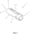
- the sleeve element preferably has an outlet opening 11 at the distal end 12.
- FIG. 4 a perspective view of the sleeve element with a partial section or a rib 21 is shown through a partial section of the sleeve element 8.
- the rib 21 is arranged vertically or longitudinally along the syringe body.
- the ribs or waves have flanks with different flank angles, one flank angle being flat and the other flank angle being steep.
- An outlet opening 11 is located at the distal end 12 of the sleeve element 8.
- the proximal end 6 of the sleeve element 8 is connected to the syringe body 1 (not in FIG Figure 4 shown) connected.
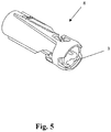
- the Figure 5 shows the sleeve element 8 with the collar element 3.
- the collar element 3 is connected to the sleeve element 8 by the guide pins.
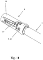
- FIG. 11 shows a perspective view of the sleeve element 8 with the collar element 3, a spring element 17 and a cap element 15.
- the cap element 15 is shown in more detail in relation to FIG Figure 13 described.
- the safety device 2 is presented in detail, in particular the movement of the guide pin and the syringe body 1 relative to the safety device 2 and the position of the lancing means 18.
- An initial position is understood to mean a syringe that has not yet been used.
- the distal end 12 of the sleeve element 8 is preferably placed directly on the skin, so that the outlet opening 11 is in contact with the skin. If the syringe body 1 is now moved in the longitudinal direction relative to the safety device 2, the guide pin is guided through the link section, as a result of which the collar element 3 is moved.
- the distal end of the lancing device 18 is arranged at the level of the outlet opening 11.
- the lancing device 18 is therefore just about to emerge from the safety device 2 so that an injection is possible.
- the lancing device 18 can then be moved further out of the safety device 2 (see FIG Fig. 9 ). If the injection has been carried out or the lancing device 18 has been moved out of the safety device 2, the user reduces the pressure on the syringe, whereby the spring force of the spring element moves the syringe body 1 relative to the safety device 2 against the longitudinal direction. The lancing device is therefore automatically moved back into the safety device 2 by the spring element.
- Figure 7 shows the sleeve element 8, which is connected to the syringe body 1 at its proximal end 6.
- the collar element is in the starting position at a proximal end of the sleeve element and the guide pin 4 of the collar element 3 is in a starting position 23 counteracts the safety device, the collar element 3 rotating when pressed against the spring force by the safety device due to the predetermined guide slot.
- the collar element or the guide pin 4 moves in the direction of the distal end 12 or the outlet opening 11 of the sleeve element 8 (shown in FIG Figure 8 ).
- the sleeve element has a guide slot 9 in which at least one guide pin 4 runs, whereby different positions of the sleeve element 8 can be realized.
- the bulges 22 snap into the ribs 21 in a position of the guide slot when the needle tip has been displaced in the sleeve element in the distal direction so that contamination of the needle tip can no longer be ruled out.
- the guide pin 4 is returned in the guide slot 9 in the direction of the proximal end 6 of the sleeve element 8, the guide pin 4 is held in the end position 24 by the design of the guide slot. This prevents the collar element from jumping back into the starting position and the needle from possibly being used again when the collar element moves back to the proximal end of the sleeve element.
- the Figures 12 and 13th show a syringe body 1 with a safety device 2 mounted thereon.
- the safety device 2 comprises a spring element, which in the present case is designed as a spiral spring.
- the cap element 15 also includes a lancing device protection device 20 and a wing element 19, which is designed in such a way that it is designed to be complementary to the recess area 14.
- the puncture protection device 20 is preferably designed essentially cylindrical and is advantageously permanently connectable or connected to the cap element 15, the puncture protection device 20 preferably being designed in such a way that it can be inserted into the sleeve element 8.
- an outer diameter of the lancing device 20 corresponds at most to the inner diameter 10 of the sleeve element.
- the dimensions of the safety device 2 are selected such that the sleeve element 8 has an inside diameter 10 which is larger than the diameter of the syringe body 1, so that the syringe body 1, the syringe body can be moved into the sleeve element 8 during a movement in the longitudinal direction forwards with respect to the safety device 2.
- the outer diameter of the sleeve element 8 or the safety device 2 is selected so that it corresponds at most to a maximum diameter of a holding device attached to the proximal end of the syringe body 1 for holding and securely setting the syringe.
Abstract
Sicherheitsvorrichtung für Spritzen, umfassend ein sich entlang einer axialen Richtung erstreckendes Hülsenelement (8), welches zumindest teilweise das Stechmittel und den Spritzenkörper umschließt, und ein Kragenelement (3), welches an einem distalen Endbereich des Spritzenkörpers anordenbar ist und die Sicherheitsvorrichtung in axialer Richtung arretiert, wobei das Kragenelement zumindest einen Führungsstift (4) aufweist, welcher in zumindest einer Führungskulisse (9) des Hülsenelements eingreift, wobei die Sicherheitsvorrichtung ein Kappenelement (15) aufweist, welches zumindest abschnittsweise über dem Hülsenelement anordenbar ist und durch welches das Hülsenelement bezüglich der Relativbewegung des Spritzenkörpers zu dem Hülsenelement arretierbar ist, wobei das Kragenelement in einer Umfangsrichtung rotierbar an dem distalen Endbereich des Spritzenkörpers angeordnet ist, wobei das Kappenelement eine Stechmittelschutzeinrichtung aufweist, in welcher das Stechmittel anordenbar ist und welche mit dem Kragenelement in Wirkkontakt bringbar ist, wodurch das Kragenelement bezüglich der Rotation arretierbar ist, wobei das Hülsenelement und das Kragenelement jeweils mit einem Verrastmechanismus (21,22) vorgesehen ist.Safety device for syringes, comprising a sleeve element (8) which extends along an axial direction and which at least partially encloses the lancing means and the syringe body, and a collar element (3) which can be arranged on a distal end region of the syringe body and which locks the safety device in the axial direction , wherein the collar element has at least one guide pin (4) which engages in at least one guide slot (9) of the sleeve element, the safety device having a cap element (15) which can be arranged at least in sections over the sleeve element and through which the sleeve element with respect to the relative movement of the syringe body can be locked to the sleeve element, the collar element being rotatably arranged in a circumferential direction on the distal end region of the syringe body, the cap element having a lancing device protection device in which the lancing device can be arranged and the like nd which can be brought into operative contact with the collar element, whereby the collar element can be locked with respect to rotation, the sleeve element and the collar element each being provided with a latching mechanism (21, 22).
Description
Die vorliegende Erfindung betrifft eine Sicherheitsvorrichtung für Spritzen, ein Verfahren zur Montage einer Sicherheitsvorrichtung, ein Spritzensicherungssystem sowie eine Spritze ausgestattet mit einer Sicherungsvorrichtung.The present invention relates to a safety device for syringes, a method for assembling a safety device, a syringe safety system and a syringe equipped with a safety device.
Bekanntermaßen wird beim Spritzensicherungssystem der Kragen mit seinen Pins, beispielsweise Führungsstiften, in einer Kurvenführung des Hülsenelements gegen eine Federkraft bis zu einem Anschlag bewegt. Die Kanüle steht aus dem Hülsenelement heraus. Somit kann eine Injektion verabreicht werden. Wird die Spritze vom Anwender abgesetzt, entspannt sich die Feder wieder. Dabei wird der Kragen mit seinen Pins in eine Verriegelungsposition bewegt. Die Spritze kann nicht wiederverwendet werden. Sollte der Injektionsvorgang abgebrochen werden, nachdem die Kanülenspitze das Hülsenelement verlassen hat, soll das Sicherungssystem eine Wiederverwendung verhindern. Der Kragen soll auch hier durch die Federkraft in die Verriegelungsposition bewegt werden. Die Kurvenführung beschreibt nicht nur eine Bewegungsrichtung in vertikaler Richtung, sondern auch in horizontaler Richtung. Deshalb wird die Feder gespannt und tordiert. Aufgrund der Torsion wird der Kragen beim Entspannen der Feder wieder in Richtung "Ausgangsstellung" rotiert. Das Sicherungssystem kann somit wieder in Ausgangsstellung gehen und wiederverwendet werden.As is known, in the syringe safety system, the collar with its pins, for example guide pins, is moved in a curved guide of the sleeve element against a spring force up to a stop. The cannula protrudes from the sleeve element. Thus, an injection can be given. If the syringe is put down by the user, the spring relaxes again. The collar and its pins are moved into a locking position. The syringe cannot be reused. If the injection process is interrupted after the cannula tip has left the sleeve element, the safety system is intended to prevent reuse. Here, too, the collar should be moved into the locking position by the spring force. The curve guide describes not only a direction of movement in the vertical direction, but also in the horizontal direction. Therefore the spring is stretched and twisted. Due to the torsion, the collar is rotated again in the direction of the "starting position" when the spring is released. The safety system can thus go back to its starting position and be reused.
Des Weiteren beschreibt beispielsweise die
Aufgabe der Erfindung ist es somit, ein Wiederverwenden der Spritze beziehungsweise der Nadel zu verhindern, nachdem die Nadel oder Kanülenspitze aus dem Hülsenelement passiert ist beziehungsweise nachdem der Führungsstift des Kragenelementes eine gewisse Position auf der Kurvenbahn / Führungskulisse des Hülsenelementes erreicht hat.The object of the invention is thus to prevent reuse of the syringe or needle after the needle or cannula tip has passed out of the sleeve element or after the guide pin of the collar element has reached a certain position on the cam track / guide slot of the sleeve element.
Eine weitere Aufgabe der vorliegenden Erfindung ist es, das Risiko des Zurückspringens des Kragenelementes in die Ausgangsstellung zu vermindern oder ganz zu vermeiden. Gelöst werden diese Aufgaben mit den Merkmalen der Ansprüche.A further object of the present invention is to reduce or completely avoid the risk of the collar element springing back into the starting position. These tasks are solved with the features of the claims.
Erfindungsgemäß ist das Hülsenelement und das Kragenelement der Sicherheitsvorrichtung jeweils mit einem Verrastmechanismus vorgesehen.According to the invention, the sleeve element and the collar element of the safety device are each provided with a latching mechanism.
Bevorzugt weist der Verrastmechanismus des Hülsenelements zumindest eine Rippe oder Welle auf, die vertikal bzw. longitudinal entlang der Spritzenlänge angeordnet ist. Vorzugsweise weist das Hülsenelement zwei gegenüberliegende Rippen auf. Vorteilhafterweise wird das Kragenelement über die Rippen des Hülsenelementes beim Drücken gegen eine Federkraft durch den Verrastmechanismus geschnappt. Dadurch wird eine Fixierung in eine Rotationsrichtung bewirkt.The latching mechanism of the sleeve element preferably has at least one rib or shaft which is arranged vertically or longitudinally along the length of the syringe. The sleeve element preferably has two opposing ribs. The collar element is advantageously snapped over the ribs of the sleeve element when pressed against a spring force by the latching mechanism. This brings about a fixation in one direction of rotation.
Die Rippen oder Wellen weisen Flanken mit unterschiedlichen Flankenwinkeln auf, die derart ausgebildet sind, dass der eine Flankenwinkel flach und der andere Flankenwinkel steil ist. Am distalen Ende des Hülsenelementes befindet sich eine Austrittsöffnung. Das proximale Ende des Hülsenelementes ist mit dem Spritzenkörper verbunden.The ribs or waves have flanks with different flank angles, which are designed in such a way that one flank angle is flat and the other flank angle is steep. There is an outlet opening at the distal end of the sleeve element. The proximal end of the sleeve element is connected to the syringe body.
Bevorzugt weist der Verrastmechanismus des Kragenelements zumindest eine Ausbuchtung auf seiner Mantelfläche mit Flanken auf, wobei die Flanken unterschiedliche Flankenwinkel aufweisen, wobei der eine Flankenwinkel flach und der andere Flankenwinkel steil ausgebildet ist.The latching mechanism of the collar element preferably has at least one bulge on its lateral surface with flanks, the flanks having different flank angles, one flank angle being flat and the other flank angle steep.
Bevorzugt rotieren das Kragenelement und das Hülsenelement unmittelbar an den Rippen und Ausbuchtungen nur in eine Richtung, beispielsweise vergleichbar mit einer Ratschenfunktion. Durch die Verrastung des Verrastmechanismus des Kragens und Hülsenelementes wird die Sicherheit vor einer Wiederverwendung der Nadelspitze gewährleistet.Preferably, the collar element and the sleeve element rotate directly on the ribs and bulges only in one direction, for example comparable to a ratchet function. The locking of the locking mechanism of the collar and sleeve element ensures that the needle point cannot be reused.
Der Innendurchmesser des Hülsenelementes und der Außendurchmesser des Kragenelementes überdecken sich in den Bereichen der Ausbuchtungen des Kragenelementes und der Rippen des Hülsenelementes. Bevorzugt wird ein Bereich des Außendurchmessers des Kragenelementes durch den Innendurchmesser des Hülsenelementes nicht überdeckt, so dass die Rippen des Hülsenelementes freistehen.The inner diameter of the sleeve element and the outer diameter of the collar element overlap in the areas of the bulges of the collar element and the ribs of the sleeve element. A region of the outer diameter of the collar element is preferably not covered by the inner diameter of the sleeve element, so that the ribs of the sleeve element are exposed.
Die Sicherheitsvorrichtung weist mindestens ein Federelement auf, das mit dem Spritzenkörper wirkverbunden ist und der Relativbewegung des Hülsenelementes zu der Sicherheitsvorrichtung entgegenwirkt, wobei das Kragenelement beim Drücken gegen die Federkraft durch die Sicherheitsvorrichtung aufgrund der vorgegebenen Führungskulisse rotiert und über die Rippen des Hülsenelementes durch den Verrastmechanismus schnappt.The safety device has at least one spring element which is operatively connected to the syringe body and counteracts the relative movement of the sleeve element to the safety device, the collar element rotating when pressed against the spring force by the safety device due to the predetermined guide slot and snapping over the ribs of the sleeve element by the locking mechanism .
Aufgrund der Flankenwinkel des Hülsenelementes und des Kragenelementes ist eine Rotation des Kragenelementes in dem Bereich der Führungskulisse, der in eine Ausgangsstellung führt, ausgeschlossen. Das Kragenelement befindet sich in der Ausgangsstellung an einem proximalen Ende des Hülsenelementes. Die Austrittsöffnung befindet sich an einem distalen Ende des Hülsenelementes.Because of the flank angles of the sleeve element and the collar element, rotation of the collar element in the area of the guide link which leads into an initial position is excluded. In the starting position, the collar element is located at a proximal end of the sleeve element. The outlet opening is located at a distal end of the sleeve element.
Bevorzugt wird das Kragenelement in dem Bereich der Führungskulisse gehalten, der in der Arretierung des Kragenelementes zum Hülsenelement ausläuft. Durch die ausgeübte Federkraft auf das Kragenelement sowie den ausgebildeten Rippen an dem Hülsenelement und den Ausbuchtungen an dem Kragenelement werden die Ausbuchtungen des Kragenelementes in die Rippen des Hülsenelementes geführt und geschnappt. Das Hülsenelement weist eine Führungskulisse auf, in welcher mindestens ein Führungsstift läuft, wodurch verschiedene Positionen des Hülsenelements realisiert werden können. Dabei findet das Schnappen der Ausbuchtungen in den Rippen in einer Position der Führungskulisse statt, wenn die Nadelspitze soweit in dem Hülsenelement in distaler Richtung verschoben wurde, so dass eine Kontamination der Nadelspitze nicht mehr ausgeschlossen werden kann. Beim Zurückführen des Führungsstiftes in der Führungskulisse Richtung proximales Ende des Hülsenelementes wird der Führungsstift durch die Ausgestaltung der Führungskulisse in der Endposition gehalten. So wird verhindert, dass das Kragenelement in die Ausgangsposition zurückspringt und die Nadel evtl. erneut zum Einsatz kommt, wenn sich das Kragenelement wieder zum proximalen Ende des Hülsenelementes bewegt.The collar element is preferably held in the region of the guide slot which runs out in the locking of the collar element towards the sleeve element. Due to the spring force exerted on the collar element and the ribs formed on the sleeve element and the bulges on the collar element, the bulges of the collar element are guided and snapped into the ribs of the sleeve element. The sleeve element has a guide slot in which at least one guide pin runs, whereby different positions of the sleeve element can be realized. The bulges in the ribs snap into place in a position of the guide slot when the needle tip has been displaced in the sleeve element in the distal direction so that contamination of the needle tip can no longer be ruled out. When returning the guide pin in the guide slot in the direction of the proximal end of the sleeve element, the guide pin is held in the end position by the design of the guide slot. This prevents the collar element from jumping back into the starting position and the needle from possibly being used again when the collar element moves back to the proximal end of the sleeve element.
Dadurch wird ein Wiederverwenden der Spritze verhindert. Und durch den Verrastmechanismus des Hülsen- und Kragenelementes ist somit eine zusätzliche Sicherheit vor Wiederverwendung der Spritze gewährleistet.This will prevent re-use of the syringe. And the locking mechanism of the sleeve and collar element ensures additional security against re-use of the syringe.
Gemäß einer Ausführungsform ist das Kragenelement im Wesentlichen als hohler Kreiszylinder ausgebildet. Bevorzugt weist der Kreiszylinder eine Mantelfläche auf, an der der zumindest eine Führungsvorsprung angeordnet ist. Vorzugsweise erstreckt sich der zumindest eine Führungsvorsprung radial von der Mantelfläche weg. Weiterhin bevorzugt ist der Führungsvorsprung als Kreiszylinder beziehungsweise als Stift ausgebildet. Vorteilhafterweise sind an der Mantelfläche zwei sich diametral gegenüberliegende Führungsvorsprünge angeordnet. Demzufolge würde auch das Hülsenelement zwei sich diametral gegenüberliegende Führungskulissen aufweisen, in denen jeweils ein Führungsvorsprung geführt wird. Erfindungsgemäß ist das Kragenelement weiterhin in einer Umfangsrichtung rotierbar an dem distalen Endbereich des Spritzenkörpers angeordnet. Bei einer Anwendung der Spritze wird die Spritze mit der Sicherheitsvorrichtung gegen die Haut des Patienten gedrückt. Durch die Relativbewegung des Spritzenkörpers zu dem Hülsenelement und die Führung des Führungsvorsprungs in der Führungskulisse wird eine Rotation des Kragenelements entlang einer Umfangsrichtung verursacht. Das Hülsenelement schiebt sich dadurch über den Spritzenkörper, wodurch das Stechmittel, welches eine Kanüle, eine Nadel oder auch eine Lanzette sein kann, durch eine entsprechende Öffnung in dem Hülsenelement hindurchtritt. Somit wird eine Rotation des Hülsenelements auf der Haut des Patienten um die Einstichstelle herum vermieden.According to one embodiment, the collar element is designed essentially as a hollow circular cylinder. The circular cylinder preferably has a lateral surface on which the at least one guide projection is arranged. The at least one guide projection preferably extends radially away from the lateral surface. Furthermore, the guide projection is preferably designed as a circular cylinder or as a pin. Advantageously, two diametrically opposite guide projections are arranged on the jacket surface. Accordingly, the sleeve element would also have two diametrically opposite guide slots, in each of which a guide projection is guided. According to the invention, the collar element is also arranged on the distal end region of the syringe body so that it can rotate in a circumferential direction. When the syringe is used, the syringe with the safety device is pressed against the patient's skin. The relative movement of the syringe body to the sleeve element and the guidance of the guide projection in the guide slot cause the collar element to rotate along a circumferential direction. The sleeve element is thereby pushed over the syringe body, as a result of which the lancing means, which can be a cannula, a needle or also a lancet, passes through a corresponding opening in the sleeve element. Rotation of the sleeve element on the patient's skin around the puncture site is thus avoided.
Gemäß der Erfindung weist das Kappenelement eine Stechmittelschutzeinrichtung auf, in welcher das Stechmittel anordenbar ist. Durch eine derartige Stechmittelschutzeinrichtung wird ein weiterer Schutz des Stechmittels vor Beschädigungen und insbesondere vor Kontamination gewährleistet.According to the invention, the cap element has a lancing device in which the lancing device can be arranged. A lancing device of this type ensures further protection of the lancing device from damage and, in particular, from contamination.
Vorzugsweise weist das Hülsenelement eine distale Öffnung auf. Bevorzugt ist dabei der Innendurchmesser der distalen Öffnung zumindest abschnittsweise größer als der Außendurchmesser der Stechmittelschutzeinrichtung, so dass die Stechmittelschutzeinrichtung innerhalb des Hülsenelements anordenbar ist.The sleeve element preferably has a distal opening. In this case, the inner diameter of the distal opening is at least partially larger than the outer diameter of the lancing device, so that the lancing device can be arranged within the sleeve element.
Erfindungsgemäß ist die Stechmittelschutzeinrichtung mit dem Kragenelement in Wirkkontakt bringbar, wodurch das Kragenelement bezüglich einer Rotation arretierbar ist. Ein solcher Wirkkontakt kann beispielweise ein reibschlüssiger Kontakt sein. Es wäre aber auch denkbar, dass die Stechmittelschutzeinrichtung und das Kragenelement zueinander korrespondierende Rasteinrichtungen aufweisen, welche eine Rotation des Kragenelements verhindern.According to the invention, the lancing device protection device can be brought into operative contact with the collar element, as a result of which the collar element can be locked with respect to rotation. Such an operative contact can be a frictional contact, for example. However, it would also be conceivable for the lancing device protection device and the collar element to have latching devices which correspond to one another and which prevent rotation of the collar element.
Gemäß einer bevorzugten Ausführungsform weisen das Kappenelement und das Hülsenelement zueinander komplementäre Rastelemente auf, so dass das Kappenelement und das Hülsenelement trennbar verrastbar sind. Es wäre vorstellbar, dass ein Rastelement eine Sollbruchstelle aufweist, welche vor der Anwendung aufgebrochen werden muss, um ein Abziehen des Kappenelements von dem Hülsenelement zu ermöglichen. Es wäre aber auch denkbar, dass ein Einrasten der Rastelemente auch nach der Anwendung der Spritze ermöglicht ist. Somit wäre es ermöglicht, dass Kappenelement nach dem Gebrauch der Spritze wieder fest auf dem Hülsenelement anzuordnen, wodurch das Hülsenelement bezüglich der Relativbewegung des Spritzenkörpers zu dem Hülsenelement wiederum arretierbar wäre. Demzufolge ist eine gefahrlose Entsorgung der gebrauchten Spritze möglich, welche somit kein Verletzungsrisiko mehr darstellt.According to a preferred embodiment, the cap element and the sleeve element have locking elements that are complementary to one another, so that the cap element and the sleeve element can be locked in a separable manner. It would be conceivable that a latching element has a predetermined breaking point which has to be broken open before use in order to enable the cap element to be pulled off the sleeve element. However, it would also be conceivable for the latching elements to snap into place even after the syringe has been used. It would thus be possible to arrange the cap element firmly on the sleeve element again after the syringe has been used, whereby the sleeve element would again be lockable with respect to the relative movement of the syringe body to the sleeve element. As a result, the used syringe can be disposed of safely, which no longer poses a risk of injury.
Gemäß einer weiteren Ausführungsform der Erfindung umfasst das Kappenelement zumindest ein flügelartiges Element, welches in zumindest einer Aufnahme des Hülsenelements aufnehmbar ist. Weiterhin bevorzugt weist das Kappenelement zwei flügelartige Elemente auf, welche diametral in jeweils zwei Aufnahmen des Hülsenelements aufnehmbar sind. Besonders bevorzugt sind die beiden flügelartigen Elemente diametral sich gegenüberliegend an dem Kappenelement angeordnet.According to a further embodiment of the invention, the cap element comprises at least one wing-like element which can be received in at least one receptacle of the sleeve element. Furthermore, the cap element preferably has two wing-like elements, which can be received diametrically in two receptacles of the sleeve element. The two wing-like elements are particularly preferably arranged diametrically opposite one another on the cap element.
Nach einer weiteren bevorzugten Ausführungsform ist zumindest ein flügelartiges Element mit dem Kragenelement in Wirkkontakt bringbar, wodurch das Kragenelement bezüglich einer Rotation arretierbar ist. Ein solcher Wirkkontakt kann beispielweise ein reibschlüssiger Kontakt sein. Es wäre aber auch denkbar, dass die Stechmittelschutzeinrichtung und das Kragenelement zueinander korrespondierende Rasteinrichtungen aufweisen, welche eine Rotation des Kragenelements verhindern.According to a further preferred embodiment, at least one wing-like element can be brought into operative contact with the collar element, as a result of which the collar element can be locked with respect to rotation. Such an operative contact can be a frictional contact, for example. But it would also be conceivable that the lancing device and the collar element have mutually corresponding locking devices which prevent rotation of the collar element.
Gemäß einer weiteren Ausführungsform ist an dem zumindest einen flügelartigen Element des Kappenelements zumindest ein Rastelement angeordnet, welches in zumindest ein komplementäres Rastelement, das in der zumindest einen Aufnahme des Hülsenelements angeordnet ist, einrastbar ist.According to a further embodiment, at least one latching element is arranged on the at least one wing-like element of the cap element, which latching element can be latched into at least one complementary latching element which is arranged in the at least one receptacle of the sleeve element.
Vorzugsweise ist das Kappenelement integral mit der Stechmittelschutzeinrichtung ausgebildet. Eine derartige Ausführung der Sicherheitsvorrichtung hat eine kostengünstige und einfache Herstellung zum Vorteil.The cap element is preferably formed integrally with the lancing device protection device. Such a design of the safety device has the advantage of being inexpensive and simple to manufacture.
Es ist aber auch denkbar, dass das Kappenelement eine distale Öffnung aufweist, wobei die distale Öffnung als Aufnahme ausgebildet ist, um die Stechmittelschutzeinrichtung aufzunehmen. Eine solche Ausgestaltung ermöglicht es, das Kappenelement und die Stechmittelschutzeinrichtung aus unterschiedlichen Materialien herzustellen. Es wäre demnach denkbar, die Stechmittelschutzeinrichtung aus einem elastischen Material, beispielsweise Gummi herzustellen. Ein solches elastische Material begünstigt eine Reduzierung des Beschädigungsrisikos des Stechmittels.However, it is also conceivable that the cap element has a distal opening, the distal opening being designed as a receptacle in order to receive the lancing device protection device. Such a configuration makes it possible to produce the cap element and the lancing device protection device from different materials. It would therefore be conceivable to manufacture the lancing device protection device from an elastic material, for example rubber. Such an elastic material favors a reduction in the risk of damage to the lancing device.
Vorzugsweise weist die Sicherheitsvorrichtung mindestens ein Federelement auf, das mit dem Spritzenkörper wirkverbunden ist und der Relativbewegung des Spritzenkörpers zu der Sicherheitsvorrichtung entgegenwirkt. Demnach bleibt die Kanüle bis zur vorgesehenen Anwendung innerhalb des Hülsenelements. Bei der Anwendung muss das Hülsenelement gegen die Federkraft verschoben werden, damit die Kanüle durch die Öffnung des Hülsenelements hindurchtreten kann. Nach Gebrauch der Spritze schiebt sich automatisch, angetrieben durch die Federkraft des Federelements, das Hülsenelement wieder über die Kanüle. Durch die Führung des Führungsvorsprungs in der Führungskulisse rotiert das Kragenelement entgegen der Umfangsrichtung. Der Anwender ist somit vor Stichverletzungen mit der gebrauchten kontaminierten Kanüle geschützt. Bevorzugt umfasst das Federelement eine Spiralfeder. Denkbar sind aber auch anderweitige Federarten, wie beispielsweise Schenkelfedern oder Torsionsfedern. Ferner wäre vorstellbar, das Federelement als ein Elastomer auszubilden.The safety device preferably has at least one spring element which is operatively connected to the syringe body and counteracts the movement of the syringe body relative to the safety device. Accordingly, the cannula remains within the sleeve element until the intended use. During use, the sleeve element must be displaced against the spring force so that the cannula can pass through the opening of the sleeve element. After the syringe has been used, the sleeve element automatically pushes itself back over the cannula, driven by the spring force of the spring element. By guiding the guide projection in the guide slot, the collar element rotates counter to the circumferential direction. The user is thus protected from puncture injuries with the used contaminated cannula. The spring element preferably comprises a spiral spring. Other types of spring, such as leg springs or torsion springs, are also conceivable. It would also be conceivable to design the spring element as an elastomer.
Durch das Federelement kann also gewährleistet werden, dass die Nadel nach Gebrauch der Spritze sicher in die Sicherheitsvorrichtung rückgeführt werden kann und der Führungsstift in die Endstellung vorzugsweise automatisch überführt werden kann.The spring element can therefore ensure that the needle can be safely returned to the safety device after the syringe has been used and that the guide pin can preferably be automatically transferred into the end position.
Dabei kann das Federelement auf verschiedene Weisen ausgestaltet sein. Vorzugsweise handelt es sich bei dem Federelement um eine Spiralfeder.The spring element can be designed in various ways. The spring element is preferably a spiral spring.
Gemäß einer bevorzugten Ausführungsform ist die Sicherheitsvorrichtung mittels eines Kragenelements mit dem Spritzenkörper zumindest wirkverbunden. Es ist dabei denkbar, dass der Führungsstift / die Führungsstifte auf dem Kragenelement angeordnet sind. Dabei ist vorteilhaft das Kragenelement einerseits mit einem Nadelaufsatz, der mit dem Spritzenkörper verbunden ist, verbunden und andererseits mittels des zumindest einen Führungsstifts mit der Sicherheitsvorrichtung verbunden, da der Führungsstift innerhalb der Führungskulisse der Sicherheitsvorrichtung angeordnet ist.According to a preferred embodiment, the safety device is at least operatively connected to the syringe body by means of a collar element. It is conceivable that the guide pin / the guide pins are arranged on the collar element. The collar element is advantageously connected on the one hand to a needle attachment that is connected to the syringe body and on the other hand connected to the safety device by means of the at least one guide pin, since the guide pin is arranged within the guide slot of the safety device.
Besonders vorteilhaft ist das Kragenelement innerhalb einer Hülse der Sicherheitsvorrichtung angeordnet. Weiter vorteilhaft weist eben diese Hülse auch die Führungskulisse auf. Gemäß einer bevorzugten Ausführungsform umfasst die Sicherheitsvorrichtung, insbesondere die Hülse, zwei Ausnehmungen, und das Kragenelement zwei Führungsstifte, wobei die Ausnehmungen und die Führungsstifte vorteilhaft gegenüberliegend ausgebildet sind, wodurch eine besonders vorteilhafte Führung gewährleistet werden kann.The collar element is particularly advantageously arranged within a sleeve of the safety device. This sleeve also advantageously has the guide slot. According to a preferred embodiment, the safety device, in particular the sleeve, comprises two recesses, and the collar element comprises two guide pins, the recesses and the guide pins advantageously being formed opposite one another, whereby a particularly advantageous guidance can be ensured.
Weiter bevorzugt ist das Federelement ebenso innerhalb der Hülse angeordnet und besonders bevorzugt mittels des Kragenelements in der Hülse gegen ein Herausfallen gesichert.More preferably, the spring element is also arranged inside the sleeve and particularly preferably secured against falling out in the sleeve by means of the collar element.
Bevorzugte Ausführungsformen der Erfindung werden nachfolgend anhand der beigefügten Zeichnungen näher erläutert.Preferred embodiments of the invention are explained in more detail below with reference to the accompanying drawings.
Es zeigen:
-
Fig. 1 - eine perspektivische Ansicht des Kragenelements; -
Fig. 2 - eine Draufsicht des Kragenelements; -
Fig. 3 - eine perspektivische Ansicht des Hülsenelements; -
Fig. 4 - eine perspektivische Ansicht des Hülsenelements mit einem Teilschnitt; -
Fig. 5 - eine perspektivische Ansicht des Hülsenelements mit dem Kragenelement; -
Fig. 6 - eine perspektivische Ansicht des Hülsenelements und des Kragenelements; -
Fig. 7 - eine perspektivische Ansicht des Hülselements und Spritzenkörper; -
Fig. 8 - eine perspektivische Ansicht des Hülsenelements mit gedrückter Federkraft; -
Fig. 9 - eine perspektivische Ansicht des Hülsenelements mit Spritzenkörper und das herausragende Stechmittel; -
Fig. 10 - eine perspektivische Ansicht des Hülsenelements mit Spritzenkörper und das eingezogene Stechmittel; -
Fig. 11 - eine perspektivische Ansicht des Hülsenelements in Sicherheitsstellung; -
Fig. 12 - ein Spritzenkörper mit darauf montierten Sicherheitsvorrichtung; -
Fig. 13 - ein Spritzenkörper mit darauf montierten Sicherheitsvorrichtung und entfernten Kappenelement.
-
Fig. 1 - a perspective view of the collar element; -
Fig. 2 - a plan view of the collar element; -
Fig. 3 - a perspective view of the sleeve element; -
Fig. 4 - a perspective view of the sleeve element with a partial section; -
Fig. 5 a perspective view of the sleeve element with the collar element; -
Fig. 6 a perspective view of the sleeve element and the collar element; -
Fig. 7 - a perspective view of the sleeve element and syringe body; -
Fig. 8 - a perspective view of the sleeve element with pressed spring force; -
Fig. 9 a perspective view of the sleeve element with the syringe body and the protruding lancing means; -
Fig. 10 a perspective view of the sleeve element with the syringe body and the retracted lancing means; -
Fig. 11 - a perspective view of the sleeve element in the safety position; -
Fig. 12 - a syringe body with a safety device mounted on it; -
Fig. 13 - a syringe body with a safety device mounted on it and a removed cap element.
Vorliegend ist auf einer Mantelfläche 7 des Kragenelements 3 ein Führungsstift 4 angeordnet. Dieser Führungsstift 4 ist dann in der Führungskulisse der Hülse anordenbar und mit dieser wirkverbindbar.In the present case, a
Zusätzlich weist das Kragenelement 3 eine oder mehrere, vorliegend zwei, Aussparungen 5 auf.In addition, the
Bevorzugt ist die Sicherheitsvorrichtung umfassend das Hülsenelement, das Kragenelement 3 und das Kappenelement bereits vormontierbar und als Ganzes mit dem Spritzenkörper mittels des Kragenelements 3 verbindbar.Preferably, the safety device comprising the sleeve element, the
In der
Die
Mit Bezug auf die
Dadurch wird ein Wiederverwenden der Spritze verhindert. Und durch den Verrastmechanismus des Hülsen- und Kragenelementes ist somit eine zusätzliche Sicherheit vor Wiederverwendung der Spritze gewährleistet.This will prevent re-use of the syringe. And the locking mechanism of the sleeve and collar element ensures additional security against re-use of the syringe.
Die
- 1: Spritzenkörper1: syringe barrel
- 2: Sicherheitsvorrichtung2: Safety device
- 3: Kragenelement3: collar element
- 4: Führungsstift / Führungsvorsprung4: Guide pin / guide projection
- 5: Aussparung5: recess
- 6: proximales Ende6: proximal end
- 7: Mantelfläche7: outer surface
- 8: Hülsenelement8: sleeve element
- 9: Führungskulisse9: Leadership backdrop
- 10: Innendurchmesser10: inside diameter
- 11: Austrittsöffnung11: outlet opening
- 12: distales Ende des Hülsenelements12: distal end of the sleeve element
- 13: Ausnehmung13: recess
- 14: Ausnahmebereich14: Exception area
- 15: Kappenelement15: cap element
- 16: Berandung16: Boundary
- 17: Federelement17: spring element
- 18: Stechmittel18: lancing agent
- 19: Flügelelement19: wing element
- 20: Stechmittelschutzeinrichtung20: Lancing device protection device
- 21: Rippen21: ribs
- 22: Ausbuchtungen22: bulges
- 23: Ausgangsstellung23: Starting position
- 24: Endposition24: end position
Claims (17)
Priority Applications (4)
| Application Number | Priority Date | Filing Date | Title |
|---|---|---|---|
| EP20163366.6A EP3881881A1 (en) | 2020-03-16 | 2020-03-16 | Accessory function of a safety device for syringes |
| CN202110231381.4A CN113398378B (en) | 2020-03-16 | 2021-03-02 | Additional functionality of safety device for syringe |
| JP2021040790A JP7220243B2 (en) | 2020-03-16 | 2021-03-12 | Additional Features of Syringe Safeguards |
| US17/201,349 US11833315B2 (en) | 2020-03-16 | 2021-03-15 | Additional function of a safety device for injection devices |
Applications Claiming Priority (1)
| Application Number | Priority Date | Filing Date | Title |
|---|---|---|---|
| EP20163366.6A EP3881881A1 (en) | 2020-03-16 | 2020-03-16 | Accessory function of a safety device for syringes |
Publications (1)
| Publication Number | Publication Date |
|---|---|
| EP3881881A1 true EP3881881A1 (en) | 2021-09-22 |
Family
ID=69844707
Family Applications (1)
| Application Number | Title | Priority Date | Filing Date |
|---|---|---|---|
| EP20163366.6A Pending EP3881881A1 (en) | 2020-03-16 | 2020-03-16 | Accessory function of a safety device for syringes |
Country Status (4)
| Country | Link |
|---|---|
| US (1) | US11833315B2 (en) |
| EP (1) | EP3881881A1 (en) |
| JP (1) | JP7220243B2 (en) |
| CN (1) | CN113398378B (en) |
Cited By (2)
| Publication number | Priority date | Publication date | Assignee | Title |
|---|---|---|---|---|
| EP4129367A1 (en) * | 2021-08-03 | 2023-02-08 | Gerresheimer Regensburg GmbH | Cap assembly for a needle |
| US11833315B2 (en) | 2020-03-16 | 2023-12-05 | Gerresheimer Regensburg Gmbh | Additional function of a safety device for injection devices |
Families Citing this family (1)
| Publication number | Priority date | Publication date | Assignee | Title |
|---|---|---|---|---|
| CN113975539B (en) * | 2021-11-25 | 2023-10-20 | 北京快舒尔医疗技术有限公司 | Injector head assembly, injector body and injector |
Citations (8)
| Publication number | Priority date | Publication date | Assignee | Title |
|---|---|---|---|---|
| EP2572745A1 (en) * | 2011-09-23 | 2013-03-27 | Sanofi-Aventis Deutschland GmbH | Needle safety device |
| EP3106193A1 (en) | 2015-06-15 | 2016-12-21 | Gerresheimer Regensburg GmbH | Safety device for syringes designed to be pre-filled |
| EP3106194A1 (en) | 2015-06-15 | 2016-12-21 | Gerresheimer Regensburg GmbH | Safety device for a syringe |
| EP3106191A1 (en) | 2015-06-15 | 2016-12-21 | Gerresheimer Regensburg GmbH | Safety device for a syringe |
| DE102015110343A1 (en) | 2015-06-26 | 2016-12-29 | Gerresheimer Regensburg Gmbh | Multi-part safety device for a syringe |
| DE102015111840A1 (en) | 2015-07-21 | 2017-01-26 | Gerresheimer Bünde Gmbh | Safety device for a syringe |
| DE102015111835A1 (en) | 2015-07-21 | 2017-01-26 | Gerresheimer Regensburg Gmbh | Safety device for a syringe |
| DE102016108870A1 (en) | 2016-05-13 | 2017-11-16 | Gerresheimer Regensburg Gmbh | Stinging agent protection device for a syringe |
Family Cites Families (11)
| Publication number | Priority date | Publication date | Assignee | Title |
|---|---|---|---|---|
| US6004296A (en) * | 1997-09-30 | 1999-12-21 | Becton Dickinson France, S.A. | Lockable safety shield assembly for a prefillable syringe |
| ES2794861T3 (en) * | 2010-07-02 | 2020-11-19 | Sanofi Aventis Deutschland | Safety device for a pre-filled syringe and injection device |
| KR101544682B1 (en) * | 2011-06-17 | 2015-08-13 | 에스에이치엘 그룹 에이비 | Injection device |
| AU2012302281B2 (en) * | 2011-08-31 | 2015-05-07 | Shl Medical Ag | Injection device |
| US10004854B2 (en) | 2012-03-07 | 2018-06-26 | West Pharmaceutical Services, Inc. | Low radial profile needle safety device |
| JP6010220B2 (en) * | 2013-08-14 | 2016-10-19 | テルモ株式会社 | Syringe |
| WO2016158627A1 (en) * | 2015-03-30 | 2016-10-06 | テルモ株式会社 | Assembly for protecting puncture needle, syringe assembly, and method for manufacturing same |
| EP3106188B1 (en) * | 2015-06-15 | 2019-02-06 | Gerresheimer Regensburg GmbH | Method for mounting a safety device on a syringe |
| FR3037807B1 (en) * | 2015-06-23 | 2017-08-11 | Biocorp Prod | SYRINGE NEEDLE COLLEE |
| WO2019033100A1 (en) | 2017-08-11 | 2019-02-14 | West Pharmaceutical Services, Inc. | Needle safety system |
| EP3881881A1 (en) | 2020-03-16 | 2021-09-22 | Gerresheimer Regensburg GmbH | Accessory function of a safety device for syringes |
-
2020
- 2020-03-16 EP EP20163366.6A patent/EP3881881A1/en active Pending
-
2021
- 2021-03-02 CN CN202110231381.4A patent/CN113398378B/en active Active
- 2021-03-12 JP JP2021040790A patent/JP7220243B2/en active Active
- 2021-03-15 US US17/201,349 patent/US11833315B2/en active Active
Patent Citations (8)
| Publication number | Priority date | Publication date | Assignee | Title |
|---|---|---|---|---|
| EP2572745A1 (en) * | 2011-09-23 | 2013-03-27 | Sanofi-Aventis Deutschland GmbH | Needle safety device |
| EP3106193A1 (en) | 2015-06-15 | 2016-12-21 | Gerresheimer Regensburg GmbH | Safety device for syringes designed to be pre-filled |
| EP3106194A1 (en) | 2015-06-15 | 2016-12-21 | Gerresheimer Regensburg GmbH | Safety device for a syringe |
| EP3106191A1 (en) | 2015-06-15 | 2016-12-21 | Gerresheimer Regensburg GmbH | Safety device for a syringe |
| DE102015110343A1 (en) | 2015-06-26 | 2016-12-29 | Gerresheimer Regensburg Gmbh | Multi-part safety device for a syringe |
| DE102015111840A1 (en) | 2015-07-21 | 2017-01-26 | Gerresheimer Bünde Gmbh | Safety device for a syringe |
| DE102015111835A1 (en) | 2015-07-21 | 2017-01-26 | Gerresheimer Regensburg Gmbh | Safety device for a syringe |
| DE102016108870A1 (en) | 2016-05-13 | 2017-11-16 | Gerresheimer Regensburg Gmbh | Stinging agent protection device for a syringe |
Cited By (2)
| Publication number | Priority date | Publication date | Assignee | Title |
|---|---|---|---|---|
| US11833315B2 (en) | 2020-03-16 | 2023-12-05 | Gerresheimer Regensburg Gmbh | Additional function of a safety device for injection devices |
| EP4129367A1 (en) * | 2021-08-03 | 2023-02-08 | Gerresheimer Regensburg GmbH | Cap assembly for a needle |
Also Published As
| Publication number | Publication date |
|---|---|
| CN113398378A (en) | 2021-09-17 |
| US11833315B2 (en) | 2023-12-05 |
| US20210283378A1 (en) | 2021-09-16 |
| JP7220243B2 (en) | 2023-02-09 |
| CN113398378B (en) | 2023-08-29 |
| JP2021151473A (en) | 2021-09-30 |
Similar Documents
| Publication | Publication Date | Title |
|---|---|---|
| DE60220362T2 (en) | Safety device for a pre-filled and needle-capped syringe | |
| EP3881881A1 (en) | Accessory function of a safety device for syringes | |
| DE60026237T2 (en) | Protective device for injection or aspiration needle | |
| EP3325053B1 (en) | Safety device for a syringe | |
| EP3106194B1 (en) | Safety device for a syringe | |
| DE60118511T2 (en) | Blood collection set | |
| DE19725680C2 (en) | Funnel-shaped cannula arrangement for catheter insertion | |
| EP3106193B1 (en) | Syringe body | |
| EP3106191B1 (en) | Safety device for a syringe | |
| EP2667804B1 (en) | Suprapubic safety cannula | |
| WO2016007981A1 (en) | Safety needle arrangement and method for drawing liquid from a body | |
| EP3325054B1 (en) | Safety device for a syringe | |
| WO2001076665A1 (en) | Needle protection system | |
| EP3313482B1 (en) | Multi-part safety device for a syringe | |
| EP3352817B1 (en) | Injection device, in particular an auto-injector | |
| DE60128469T2 (en) | CATHETER AND INSERT NEEDLE ARRANGEMENT WITH NEEDLE PROTECTION | |
| DE102007009340A1 (en) | Needle protection device for injection unit, has needle support, which has needle protective sleeve and integrated needle support removal device for removing needle support of injection unit | |
| WO2020104430A1 (en) | Device for depositing an element by means of a cannula | |
| EP2626007B1 (en) | Safety device for a cannula | |
| EP4262591A1 (en) | Suprapubic cannula | |
| EP3824928A1 (en) | Safety cannula unit, method for its operation and usage |
Legal Events
| Date | Code | Title | Description |
|---|---|---|---|
| PUAI | Public reference made under article 153(3) epc to a published international application that has entered the european phase |
Free format text: ORIGINAL CODE: 0009012 |
|
| STAA | Information on the status of an ep patent application or granted ep patent |
Free format text: STATUS: REQUEST FOR EXAMINATION WAS MADE |
|
| 17P | Request for examination filed |
Effective date: 20200316 |
|
| AK | Designated contracting states |
Kind code of ref document: A1 Designated state(s): AL AT BE BG CH CY CZ DE DK EE ES FI FR GB GR HR HU IE IS IT LI LT LU LV MC MK MT NL NO PL PT RO RS SE SI SK SM TR |