EP3881159B1 - Pedal assembly for a motor vehicle - Google Patents
Pedal assembly for a motor vehicle Download PDFInfo
- Publication number
- EP3881159B1 EP3881159B1 EP18807243.3A EP18807243A EP3881159B1 EP 3881159 B1 EP3881159 B1 EP 3881159B1 EP 18807243 A EP18807243 A EP 18807243A EP 3881159 B1 EP3881159 B1 EP 3881159B1
- Authority
- EP
- European Patent Office
- Prior art keywords
- pedal
- base plate
- single base
- housed
- assembly
- Prior art date
- Legal status (The legal status is an assumption and is not a legal conclusion. Google has not performed a legal analysis and makes no representation as to the accuracy of the status listed.)
- Active
Links
Images

Classifications
-
- G—PHYSICS
- G05—CONTROLLING; REGULATING
- G05G—CONTROL DEVICES OR SYSTEMS INSOFAR AS CHARACTERISED BY MECHANICAL FEATURES ONLY
- G05G1/00—Controlling members, e.g. knobs or handles; Assemblies or arrangements thereof; Indicating position of controlling members
- G05G1/30—Controlling members actuated by foot
- G05G1/36—Mounting units comprising an assembly of two or more pedals, e.g. for facilitating mounting
-
- B—PERFORMING OPERATIONS; TRANSPORTING
- B60—VEHICLES IN GENERAL
- B60K—ARRANGEMENT OR MOUNTING OF PROPULSION UNITS OR OF TRANSMISSIONS IN VEHICLES; ARRANGEMENT OR MOUNTING OF PLURAL DIVERSE PRIME-MOVERS IN VEHICLES; AUXILIARY DRIVES FOR VEHICLES; INSTRUMENTATION OR DASHBOARDS FOR VEHICLES; ARRANGEMENTS IN CONNECTION WITH COOLING, AIR INTAKE, GAS EXHAUST OR FUEL SUPPLY OF PROPULSION UNITS IN VEHICLES
- B60K26/00—Arrangement or mounting of propulsion-unit control devices in vehicles
- B60K26/02—Arrangement or mounting of propulsion-unit control devices in vehicles of initiating means or elements
-
- B—PERFORMING OPERATIONS; TRANSPORTING
- B60—VEHICLES IN GENERAL
- B60T—VEHICLE BRAKE CONTROL SYSTEMS OR PARTS THEREOF; BRAKE CONTROL SYSTEMS OR PARTS THEREOF, IN GENERAL; ARRANGEMENT OF BRAKING ELEMENTS ON VEHICLES IN GENERAL; PORTABLE DEVICES FOR PREVENTING UNWANTED MOVEMENT OF VEHICLES; VEHICLE MODIFICATIONS TO FACILITATE COOLING OF BRAKES
- B60T7/00—Brake-action initiating means
- B60T7/02—Brake-action initiating means for personal initiation
- B60T7/04—Brake-action initiating means for personal initiation foot actuated
- B60T7/06—Disposition of pedal
-
- G—PHYSICS
- G05—CONTROLLING; REGULATING
- G05G—CONTROL DEVICES OR SYSTEMS INSOFAR AS CHARACTERISED BY MECHANICAL FEATURES ONLY
- G05G1/00—Controlling members, e.g. knobs or handles; Assemblies or arrangements thereof; Indicating position of controlling members
- G05G1/30—Controlling members actuated by foot
- G05G1/44—Controlling members actuated by foot pivoting
Definitions
- the present invention relates to a pedal assembly for a motor vehicle according to the preamble of claim 1.
- Such pedal assemblies for motor vehicles with at least one support and at least two pedals, each comprising a pedal arm mounted to said at least one support and pivotable around a corresponding pivot axis, a sensor for detecting a rotational movement of said pedal arm around said pivot axis and an interface for an electrical contact of said sensor with a control unit of said motor vehicle, are well known in different embodiments.
- a pedal assembly for a motor vehicle is known, too.
- This pedal assembly is designed as a modular pedal assembly with two frame-like supports and two pedals, each comprising a pedal arm mounted to the corresponding support and pivotable around a corresponding pivot axis.
- a main advantage of the pedal assembly for a motor vehicle according to the invention is, that the inventive pedal assembly shows an easy design, thus can be realized with less effort. Furthermore, the inventive pedal assembly can be manufactured with less material and less assembly work. Therefore, the inventive pedal assembly for a motor vehicle can be cost saving. This can be achieved by the inventive pedal assembly for a motor vehicle.
- the design of the pedal assembly for a motor vehicle according to the invention can be of any suitable shape, material, dimension and number of pedals as well as number of pedals housed by said single base plate.
- at least two of said at least two pedals are housed by said single base plate. That way, the design of the pedal assembly for a motor vehicle according to the invention is further simplified.
- the pedal assembly for a motor vehicle according to the invention is, that said single base plate is designed, that said at least one pedal housed by said single base plate is mountable from a rear side of said single base plate, whereat said rear side is facing a frame of said motor vehicle said pedal assembly is mounted to.
- the design of the inventive pedal assembly for a motor vehicle according to the invention is furthermore simplified. A separate cover for housing this pedal is not necessary.
- a major problem of pedal assemblies for motor vehicles is, that there is always a risk of getting debris like small stones into the mechanism of the pedal assembly.
- the pedal assembly according to the aforementioned embodiment of the invention solves or reduces this problem by employing an easy design, too. This is especially true for pedal assemblies designed for so called standing pedals for motor vehicles.
- said single base plate is comprising a frame part for said at least one pedal housed by said single base plate. That way, the single base plate can be realized with less material and shows an easy design, too.
- said pedal arm of said at least one pedal housed by said single base plate comprises a central part corresponding to said single base plate and an actuation part linked to said central part in a power transmitting manner.
- the assembly of the at least one pedal housed by said single base plate is simplified.
- the size of the pedal arm opening for said pedal arm of said at least one pedal housed by said single base plate can be reduced.
- the risk of getting debris like small stones into the mechanism of the pedal assembly can be reduced, too.
- a further advantageous development of the pedal assembly for a motor vehicle according to the invention is, that said at least two pedals comprise at least one pedal not housed by said single base plate, whereat said at least one pedal not housed by said single base plate is housed by a separate cover mounted to said single base plate. That way, the assembly of said at least one pedal not housed by said single base plate can be done from a front side of said single base plate positioned opposite to a rear side of said single base plate facing a frame of said motor vehicle the inventive pedal assembly is mounted to. Moreover, said pedal housed by said separate cover mounted to said single base plate can be accessed quite easily without the need for dismounting the inventive pedal assembly form said frame of said motor vehicle.
- said sensor of said pedal housed by said single base plate is designed as a separate sensor module and incorporated through a sensor opening of said single base plate.
- said sensor of said pedal housed by said single base plate can be assembled to the single base plate quite easily.
- said sensor can be preconfigured and/or sourced from a supplier more easily.
- said interface corresponding to said sensor of said pedal housed by said single base plate is designed as an integral part of said separate sensor module.
- said interface and said sensor corresponding to said interface can be preconfigured and/or sourced from a supplier as a single part. No further workload for electrically and mechanically connecting said interface to said separate sensor module or to another type of sensor configuration has to be spent.
- said single base plate and/or said separate cover can be of any kind, shape, material, dimension and position to the rest of the inventive pedal assembly for a motor vehicle.
- said single base plate and/or said separate cover are/is built from plastics. Plastics are available in a broad variety with different characteristics. Furthermore, plastics are lightweight material and easy to process.
- the pedal assembly for a motor vehicle according to the invention is, that said at least two pedals of said pedal assembly are designed as an accelerator pedal and a brake pedal. Every motor vehicle, with an automatic gearbox or with a manual gearbox, does have at least an accelerator pedal and a brake pedal.
- the pedal assembly for a motor vehicle according to this embodiment can be produced in a high number of units.
- the pedal assembly for a motor vehicle according to the invention may comprise other kinds of pedals, too.
- the inventive pedal assembly may comprise three pedals, namely a clutch pedal, a brake pedal and an accelerator pedal.
- Other embodiments may comprise only a clutch pedal and a brake pedal.
- Each pedal arm 10, 12 is mounted to said single support 4 and pivotable around a corresponding pivot axis, namely a pivot axis of said pedal arm 10 of said accelerator pedal 6 and a pivot axis of said pedal arm 12 of said brake pedal 8.
- Both of said two pedals 6, 8 are housed by said single base plate 4, whereat said pedal arm 10 of said accelerator pedal 6 is extending through a pedal arm opening 7 of said single base plate 4 and said pedal arm 12 of said brake pedal 8 is extending through a pedal arm opening 9 of said single base plate 4.
- Said pedal arms 10, 12 as well as said corresponding pedal arm openings 7, 9 are shown in an exploded view in Fig. 2 . Said motor vehicle is not displayed.
- said pedal assembly 2 comprises a sensor 18 for detecting a rotational movement of said pedal arm 10 of said accelerator pedal 6 around said pivot axis 14 and a sensor 20 for detecting a rotational movement of said pedal arm 12 of said brake pedal 8 around said pivot axis 16.
- Each of said sensors 18, 20 of said accelerator pedal 6 and said brake pedal 8 is designed as a separate sensor module and incorporated through a sensor opening 22, 24 of said single base plate 4.
- Said separate sensor module 18 of said accelerator pedal 6 and said sensor module 20 of said brake pedal 8 as well as said corresponding sensor openings 22, 24 of said single base plate 4 are shown in an exploded view in Fig. 2 .
- An interface 26 for an electrical contact of said sensor 18 with a control unit of said motor vehicle and an interface 28 for an electrical contact of said sensor 20 with said control unit of said motor vehicle each is incorporated in said corresponding separate sensor module 18, 20, namely said interface 26 is incorporated in said separate sensor module 18 corresponding to said accelerator pedal 6 and said interface 28 is incorporated in said separate sensor module 20 corresponding to said brake pedal 8.
- said interface 26 is designed as an integral part of said separate sensor module 18 and said interface 28 is designed as an integral part of said separate sensor module 20. Said control unit is not displayed.
- Fig. 3 displays said pedal assembly 2 in a second perspective view showing said pedal assembly 2 from a rear side of said base plate 4, which is facing a frame of said motor vehicle said pedal assembly 2 is mounted to. Said frame of said motor vehicle is not displayed.
- said single base plate 4 is comprising a frame part 30 for said accelerator pedal 6 and said brake pedal 8, each housed by said single base plate 4.
- said accelerator pedal 6 and said brake pedal 8 each are assembled from said rear side of said single base plate 4 via said frame part 30 of said single base plate 4; see Fig. 3 .
- Said pedal arms 10, 12 of said accelerator pedal 6 and said brake pedal 8 each are fed through said corresponding pedal arm openings 7, 9 of said single base plate 4 from said rear side of said single base plate 4.
- said pedal arm 10 of said accelerator pedal 6 is extending through said pedal arm opening 7 and said pedal arm 12 of said brake pedal 8 is extending through said pedal arm opening 9. See Fig. 1 .
- Said separate sensor module 18 of said accelerator pedal 6 is inserted into said sensor opening 22 of said single base plate 4 and said separate sensor module 20 of said brake pedal 8 is inserted into said sensor opening 24 of said single base plate 4. See Fig. 2 .
- Said pedal arm 10 is pivoted around said pivot axis 14 of said pedal arm 10.
- This pivot action of said pedal arm 10 around said pivot axis 14 is detected by said separate sensor module 18 corresponding to said accelerator pedal 6.
- Said aforementioned pivot action of said accelerator pedal 6 is transferred to said control unit of said motor vehicle via said interface 26 of said separate sensor module 18.
- said pedal arm 10 is pivoted in opposite direction around said pivot axis 14 of said pedal arm 10. This pivot action of said accelerator pedal 6 is transferred to said control unit of said motor vehicle, too.
- the function of said brake pedal 8 is analog to the function of said accelerator pedal 6 explained above.
- said user of said pedal assembly 2 is pressing said pedal arm 12 of said brake pedal 8 in order to decelerate said motor vehicle.
- Said pedal arm 12 is pivoted around said pivot axis 16 of said pedal arm 12.
- This pivot action of said pedal arm 12 around said pivot axis 16 is detected by said separate sensor module 20 corresponding to said brake pedal 8.
- Said aforementioned pivot action of said brake pedal 8 is transferred to said control unit of said motor vehicle via said interface 28 of said separate sensor module 20.
- said pedal arm 12 is pivoted in opposite direction around said pivot axis 16 of said pedal arm 12. This pivot action of said brake pedal 8 is also transferred to said control unit of said motor vehicle.
- the invention is not limited to the exemplary embodiment of the pedal assembly for a motor vehicle according to the invention discussed before.
- the invention is not limited to an inventive pedal assembly comprising an accelerator pedal and a brake pedal.
- another embodiment of the invention may comprise an acceleration pedal, a brake pedal and a clutch pedal.
- Still another embodiment of the invention may comprise a brake pedal and a clutch pedal.
- said pedal arm of said at least one pedal housed by said single base plate may comprise a central part corresponding to said single base plate and an actuation part linked to said central part in a power transmitting manner.
- the assembly of the at least one pedal housed by said single base plate is simplified.
- the size of the pedal arm opening for said pedal arm of said at least one pedal housed by said single base plate can be reduced.
- the risk of getting debris like small stones into the mechanism of the pedal assembly can be reduced, too.
- said at least two pedals comprise at least one pedal not housed by said single base plate, whereat said at least one pedal not housed by said single base plate is housed by a separate cover mounted to said single base plate. That way, the assembly of said at least one pedal not housed by said single base plate can be done from a front side of said single base plate positioned opposite to a rear side of said single base plate facing a frame of said motor vehicle the inventive pedal assembly is mounted to. Moreover, said pedal housed by said separate cover mounted to said single base plate can be accessed quite easily without the need for dismounting the inventive pedal assembly form said frame of said motor vehicle.
- said separate cover is built from plastics. Plastics are available in a broad variety with different characteristics. Furthermore, plastics are lightweight materials and easy to process.
- a main advantage of the pedal assembly for a motor vehicle according to the invention is, that the inventive pedal assembly shows an easy design, thus can be realized with less effort. Furthermore, the inventive pedal assembly can be manufactured with less material and less assembly work. Therefore, the inventive pedal assembly for a motor vehicle can be cost saving. This can be achieved by the inventive pedal assembly for a motor vehicle.
Landscapes
- Engineering & Computer Science (AREA)
- Physics & Mathematics (AREA)
- General Physics & Mathematics (AREA)
- Automation & Control Theory (AREA)
- Transportation (AREA)
- Mechanical Engineering (AREA)
- Chemical & Material Sciences (AREA)
- Combustion & Propulsion (AREA)
- Auxiliary Drives, Propulsion Controls, And Safety Devices (AREA)
- Mechanical Control Devices (AREA)
Description
- The present invention relates to a pedal assembly for a motor vehicle according to the preamble of claim 1.
- Such pedal assemblies for motor vehicles, with at least one support and at least two pedals, each comprising a pedal arm mounted to said at least one support and pivotable around a corresponding pivot axis, a sensor for detecting a rotational movement of said pedal arm around said pivot axis and an interface for an electrical contact of said sensor with a control unit of said motor vehicle, are well known in different embodiments.
- Furthermore, from the
DE 10 2007 059 376 A1 a pedal assembly for a motor vehicle is known, too. This pedal assembly is designed as a modular pedal assembly with two frame-like supports and two pedals, each comprising a pedal arm mounted to the corresponding support and pivotable around a corresponding pivot axis. - From
FR 2 796 174 A1 - It is an object of the invention to provide a pedal assembly for a motor vehicle, which shows an easy design.
- This object of the invention is solved by a pedal assembly for a motor vehicle according to claim 1.
- A main advantage of the pedal assembly for a motor vehicle according to the invention is, that the inventive pedal assembly shows an easy design, thus can be realized with less effort. Furthermore, the inventive pedal assembly can be manufactured with less material and less assembly work. Therefore, the inventive pedal assembly for a motor vehicle can be cost saving. This can be achieved by the inventive pedal assembly for a motor vehicle.
- Further advantageous developments of the inventive pedal assembly for a motor vehicle are apparent from the sub-claims as well as from the following description of an exemplary embodiment of the pedal assembly for a motor vehicle according to the invention by means of the attached Figures.
- Basically, the design of the pedal assembly for a motor vehicle according to the invention can be of any suitable shape, material, dimension and number of pedals as well as number of pedals housed by said single base plate. Advantageously, at least two of said at least two pedals are housed by said single base plate. That way, the design of the pedal assembly for a motor vehicle according to the invention is further simplified.
- The pedal assembly for a motor vehicle according to the invention is, that said single base plate is designed, that said at least one pedal housed by said single base plate is mountable from a rear side of said single base plate, whereat said rear side is facing a frame of said motor vehicle said pedal assembly is mounted to. Hereby, the design of the inventive pedal assembly for a motor vehicle according to the invention is furthermore simplified. A separate cover for housing this pedal is not necessary. Moreover, a major problem of pedal assemblies for motor vehicles is, that there is always a risk of getting debris like small stones into the mechanism of the pedal assembly. The pedal assembly according to the aforementioned embodiment of the invention solves or reduces this problem by employing an easy design, too. This is especially true for pedal assemblies designed for so called standing pedals for motor vehicles.
- Furthermore according to the invention said single base plate is comprising a frame part for said at least one pedal housed by said single base plate. That way, the single base plate can be realized with less material and shows an easy design, too.
- Another advantageous development of the pedal assembly according to the invention is, that said pedal arm of said at least one pedal housed by said single base plate comprises a central part corresponding to said single base plate and an actuation part linked to said central part in a power transmitting manner. Hereby, the assembly of the at least one pedal housed by said single base plate is simplified. Furthermore, the size of the pedal arm opening for said pedal arm of said at least one pedal housed by said single base plate can be reduced. Thus, the risk of getting debris like small stones into the mechanism of the pedal assembly can be reduced, too.
- A further advantageous development of the pedal assembly for a motor vehicle according to the invention is, that said at least two pedals comprise at least one pedal not housed by said single base plate, whereat said at least one pedal not housed by said single base plate is housed by a separate cover mounted to said single base plate. That way, the assembly of said at least one pedal not housed by said single base plate can be done from a front side of said single base plate positioned opposite to a rear side of said single base plate facing a frame of said motor vehicle the inventive pedal assembly is mounted to. Moreover, said pedal housed by said separate cover mounted to said single base plate can be accessed quite easily without the need for dismounting the inventive pedal assembly form said frame of said motor vehicle.
- Another advantageous development of the pedal assembly for a motor vehicle according to the invention is, that said sensor of said pedal housed by said single base plate is designed as a separate sensor module and incorporated through a sensor opening of said single base plate. Hereby, said sensor of said pedal housed by said single base plate can be assembled to the single base plate quite easily. Furthermore, said sensor can be preconfigured and/or sourced from a supplier more easily.
- A particular preferable development of the aforementioned embodiment of the pedal assembly for a motor vehicle according to the invention is, that said interface corresponding to said sensor of said pedal housed by said single base plate is designed as an integral part of said separate sensor module. Thus, said interface and said sensor corresponding to said interface can be preconfigured and/or sourced from a supplier as a single part. No further workload for electrically and mechanically connecting said interface to said separate sensor module or to another type of sensor configuration has to be spent.
- In general, said single base plate and/or said separate cover can be of any kind, shape, material, dimension and position to the rest of the inventive pedal assembly for a motor vehicle. Advantageously, said single base plate and/or said separate cover are/is built from plastics. Plastics are available in a broad variety with different characteristics. Furthermore, plastics are lightweight material and easy to process.
- Another advantageous development of the pedal assembly for a motor vehicle according to the invention is, that said at least two pedals of said pedal assembly are designed as an accelerator pedal and a brake pedal. Every motor vehicle, with an automatic gearbox or with a manual gearbox, does have at least an accelerator pedal and a brake pedal. Thus, the pedal assembly for a motor vehicle according to this embodiment can be produced in a high number of units. Despite this, the pedal assembly for a motor vehicle according to the invention may comprise other kinds of pedals, too. For example, the inventive pedal assembly may comprise three pedals, namely a clutch pedal, a brake pedal and an accelerator pedal. Other embodiments may comprise only a clutch pedal and a brake pedal.
- The Figures are schematic illustrations of a pedal assembly for a motor vehicle according to the invention, wherein only the details necessary for the understanding of the invention are shown. Parts with the same function are marked by the same reference numbers.
- It is shown by:
- Fig. 1
- an embodiment of the pedal assembly for a motor vehicle according to the invention in a perspective view facing a front side of the pedal assembly,
- Fig. 2
- the embodiment of
Fig. 1 in an exploded view and - Fig. 3
- the embodiment of
Fig. 1 in a perspective view facing a rear side of the pedal assembly. -
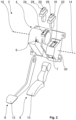
Fig. 1 displays an embodiment of apedal assembly 2 for a motor vehicle in a first perspective view with asingle support 4 and two pedals, namely anaccelerator pedal 6 and abrake pedal 8. Said first perspective view is showing saidsingle support 4 from a front side of saidsingle support 4, which is facing a user of saidpedal assembly 2 and arranged opposite to a rear side of saidsingle support 4. Saidsingle support 4 is designed as a single base plate for said twopedals accelerator pedal 6 comprises apedal arm 10 and saidbrake pedal 8 comprises apedal arm 12. Eachpedal arm single support 4 and pivotable around a corresponding pivot axis, namely a pivot axis of saidpedal arm 10 of saidaccelerator pedal 6 and a pivot axis of saidpedal arm 12 of saidbrake pedal 8. Both of said twopedals single base plate 4, whereat saidpedal arm 10 of saidaccelerator pedal 6 is extending through a pedal arm opening 7 of saidsingle base plate 4 and saidpedal arm 12 of saidbrake pedal 8 is extending through a pedal arm opening 9 of saidsingle base plate 4. Saidpedal arms pedal arm openings Fig. 2 . Said motor vehicle is not displayed. - Said pivot axis of said
pedal arm 10 of saidaccelerator pedal 6 is symbolized by abroken line 14 and said pivot axis of saidpedal arm 12 of saidbrake pedal 8 is symbolized by abroken line 16. Furthermore, saidpedal assembly 2 comprises asensor 18 for detecting a rotational movement of saidpedal arm 10 of saidaccelerator pedal 6 around saidpivot axis 14 and asensor 20 for detecting a rotational movement of saidpedal arm 12 of saidbrake pedal 8 around saidpivot axis 16. Each of saidsensors accelerator pedal 6 and saidbrake pedal 8 is designed as a separate sensor module and incorporated through asensor opening single base plate 4. Saidseparate sensor module 18 of saidaccelerator pedal 6 and saidsensor module 20 of saidbrake pedal 8 as well as said correspondingsensor openings single base plate 4 are shown in an exploded view inFig. 2 . - An
interface 26 for an electrical contact of saidsensor 18 with a control unit of said motor vehicle and aninterface 28 for an electrical contact of saidsensor 20 with said control unit of said motor vehicle each is incorporated in said correspondingseparate sensor module interface 26 is incorporated in saidseparate sensor module 18 corresponding to saidaccelerator pedal 6 and saidinterface 28 is incorporated in saidseparate sensor module 20 corresponding to saidbrake pedal 8. Thus, saidinterface 26 is designed as an integral part of saidseparate sensor module 18 and saidinterface 28 is designed as an integral part of saidseparate sensor module 20. Said control unit is not displayed. -
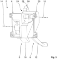
Fig. 3 displays saidpedal assembly 2 in a second perspective view showing saidpedal assembly 2 from a rear side of saidbase plate 4, which is facing a frame of said motor vehicle saidpedal assembly 2 is mounted to. Said frame of said motor vehicle is not displayed. As can be seen best fromFig. 3 , saidsingle base plate 4 is comprising aframe part 30 for saidaccelerator pedal 6 and saidbrake pedal 8, each housed by saidsingle base plate 4. - In the following, the function of said embodiment of a pedal assembly for a motor vehicle according to the invention is explained by means of
Fig. 1 to 3 . - In order to manufacture said
pedal assembly 2 saidaccelerator pedal 6 and saidbrake pedal 8 each are assembled from said rear side of saidsingle base plate 4 via saidframe part 30 of saidsingle base plate 4; seeFig. 3 . Saidpedal arms accelerator pedal 6 and saidbrake pedal 8 each are fed through said correspondingpedal arm openings single base plate 4 from said rear side of saidsingle base plate 4. Thus, after the assembly of saidaccelerator pedal 6 and saidbrake pedal 8 saidpedal arm 10 of saidaccelerator pedal 6 is extending through saidpedal arm opening 7 and saidpedal arm 12 of saidbrake pedal 8 is extending through saidpedal arm opening 9. SeeFig. 1 . - Said
separate sensor module 18 of saidaccelerator pedal 6 is inserted into saidsensor opening 22 of saidsingle base plate 4 and saidseparate sensor module 20 of saidbrake pedal 8 is inserted into saidsensor opening 24 of saidsingle base plate 4. SeeFig. 2 . - A user of said
pedal assembly 2, namely a driver of said motor vehicle, is pressing saidpedal arm 10 of saidaccelerator pedal 6 in order to accelerate said motor vehicle. Saidpedal arm 10 is pivoted around saidpivot axis 14 of saidpedal arm 10. This pivot action of saidpedal arm 10 around saidpivot axis 14 is detected by saidseparate sensor module 18 corresponding to saidaccelerator pedal 6. Said aforementioned pivot action of saidaccelerator pedal 6 is transferred to said control unit of said motor vehicle via saidinterface 26 of saidseparate sensor module 18. In case said user is no longer pressing saidpedal arm 10 of saidaccelerator pedal 6, saidpedal arm 10 is pivoted in opposite direction around saidpivot axis 14 of saidpedal arm 10. This pivot action of saidaccelerator pedal 6 is transferred to said control unit of said motor vehicle, too. - The function of said
brake pedal 8 is analog to the function of saidaccelerator pedal 6 explained above. Thus, said user of saidpedal assembly 2 is pressing saidpedal arm 12 of saidbrake pedal 8 in order to decelerate said motor vehicle. Saidpedal arm 12 is pivoted around saidpivot axis 16 of saidpedal arm 12. This pivot action of saidpedal arm 12 around saidpivot axis 16 is detected by saidseparate sensor module 20 corresponding to saidbrake pedal 8. Said aforementioned pivot action of saidbrake pedal 8 is transferred to said control unit of said motor vehicle via saidinterface 28 of saidseparate sensor module 20. In case said user is no longer pressing saidpedal arm 12 of saidbrake pedal 8, saidpedal arm 12 is pivoted in opposite direction around saidpivot axis 16 of saidpedal arm 12. This pivot action of saidbrake pedal 8 is also transferred to said control unit of said motor vehicle. - The invention is not limited to the exemplary embodiment of the pedal assembly for a motor vehicle according to the invention discussed before.
- Of course, the invention is not limited to an inventive pedal assembly comprising an accelerator pedal and a brake pedal. For example, another embodiment of the invention may comprise an acceleration pedal, a brake pedal and a clutch pedal. Still another embodiment of the invention may comprise a brake pedal and a clutch pedal.
- In contrast to the embodiment of the invention explained, said pedal arm of said at least one pedal housed by said single base plate may comprise a central part corresponding to said single base plate and an actuation part linked to said central part in a power transmitting manner. Hereby, the assembly of the at least one pedal housed by said single base plate is simplified. Furthermore, the size of the pedal arm opening for said pedal arm of said at least one pedal housed by said single base plate can be reduced. Thus, the risk of getting debris like small stones into the mechanism of the pedal assembly can be reduced, too.
- Furthermore, it is possible, that said at least two pedals comprise at least one pedal not housed by said single base plate, whereat said at least one pedal not housed by said single base plate is housed by a separate cover mounted to said single base plate. That way, the assembly of said at least one pedal not housed by said single base plate can be done from a front side of said single base plate positioned opposite to a rear side of said single base plate facing a frame of said motor vehicle the inventive pedal assembly is mounted to. Moreover, said pedal housed by said separate cover mounted to said single base plate can be accessed quite easily without the need for dismounting the inventive pedal assembly form said frame of said motor vehicle. A preferred embodiment of the aforementioned embodiment could be, that said separate cover is built from plastics. Plastics are available in a broad variety with different characteristics. Furthermore, plastics are lightweight materials and easy to process.
- A main advantage of the pedal assembly for a motor vehicle according to the invention is, that the inventive pedal assembly shows an easy design, thus can be realized with less effort. Furthermore, the inventive pedal assembly can be manufactured with less material and less assembly work. Therefore, the inventive pedal assembly for a motor vehicle can be cost saving. This can be achieved by the inventive pedal assembly for a motor vehicle.
-
- 2
- Pedal assembly
- 4
- Single support, designed as a single base plate
- 6
- Accelerator pedal
- 7
- Pedal arm opening of
single base plate 4 forpedal arm 10 - 8
- Brake pedal
- 9
- Pedal arm opening of
single base plate 4 forpedal arm 12 - 10
- Pedal arm of
accelerator pedal 6 - 12
- Pedal arm of
brake pedal 8 - 14
- Pivot axis of
pedal arm 10 - 16
- Pivot axis of
pedal arm 12 - 18
- Separate sensor module for
accelerator pedal 6 - 20
- Separate sensor module for
brake pedal 8 - 22
- Sensor opening of
single base plate 4 forseparate sensor module 18 - 24
- Sensor opening of
single base plate 4 forseparate sensor module 20 - 26
- Interface of
separate sensor module 18 - 28
- Interface of
separate sensor module 20 - 30
- Frame part of
single base plate 4
Claims (8)
- Pedal assembly (2) for a motor vehicle with at least one support (4) and at least two pedals (6, 8), each comprising a pedal arm (10, 12) mounted tosaid at least one support (4) and pivotable around a corresponding pivot axis (14, 16), a sensor (18, 20) for detecting a rotational movement of said pedal arm (10, 12) around said pivot axis (14, 16) and an interface (26, 28) for an electrical contact of said sensor (18, 20) with a control unit of said motor vehicle, whereinsaid at least one support (4) is designed as a single base plate for said at least two pedals (6, 8) and at least one of said at least two pedals (6, 8) is housed by said single base plate (4), whereat said pedal arm (10, 12) of said housed pedal (6, 8) is extending through a pedal arm opening (7, 9) of said single base plate (4) characterized in thatsaid single base plate (4) is designed, that said at least one pedal (6, 8) housed by said single base plate (4) is mountable from a rear side of said single base plate (4), whereat said rear side is facing a frame of said motor vehicle said pedal assembly (2) is mounted to,said single base plate (4) is comprising a frame part (30) for said at least one pedal (6, 8) housed by said single base plate (4).
- Pedal assembly (2) according to claim 1,
wherein
at least two of said at least two pedals (6, 8) are housed by said single base plate (4). - Pedal assembly according to one of the claims 1 to 2,
wherein
said pedal arm of said at least one pedal housed by said single base plate comprises a central part corresponding to said single base plate and an actuation part linked to said central part in a power transmitting manner. - Pedal assembly according to one of the claims 1 to 3,
wherein
said at least two pedals comprise at least one pedal not housed by said single base plate, whereat said at least one pedal not housed by said single base plate is housed by a separate cover mounted to said single base plate. - Pedal assembly (2) according to one of the claims 1 to 4,
wherein
said sensor (18, 20) of said pedal (6, 8) housed by said single base plate (4) is designed as a separate sensor module and incorporated through a sensor opening (22, 24) of said single base plate (4). - Pedal assembly (2) according to claim 5,
wherein
said interface (26, 28) corresponding to said sensor (18, 20) of said pedal (6, 8) housed by said single base plate (4) is designed as an integral part of said separate sensor module (18, 20). - Pedal assembly (2) according to one of the claims 1 to 6,
wherein
said single base plate (4) and/or said separate cover are/is built from plastics. - Pedal assembly (2) according to one of the claims 1 to 7,
wherein
said at least two pedals (6, 8) of said pedal assembly (2) are designed as an accelerator pedal (6) and a brake pedal (8).
Applications Claiming Priority (1)
| Application Number | Priority Date | Filing Date | Title |
|---|---|---|---|
| PCT/EP2018/081382 WO2020098943A1 (en) | 2018-11-15 | 2018-11-15 | Pedal assembly for a motor vehicle |
Publications (2)
| Publication Number | Publication Date |
|---|---|
| EP3881159A1 EP3881159A1 (en) | 2021-09-22 |
| EP3881159B1 true EP3881159B1 (en) | 2024-08-07 |
Family
ID=64426881
Family Applications (1)
| Application Number | Title | Priority Date | Filing Date |
|---|---|---|---|
| EP18807243.3A Active EP3881159B1 (en) | 2018-11-15 | 2018-11-15 | Pedal assembly for a motor vehicle |
Country Status (4)
| Country | Link |
|---|---|
| US (1) | US20210271285A1 (en) |
| EP (1) | EP3881159B1 (en) |
| CN (1) | CN112912817A (en) |
| WO (1) | WO2020098943A1 (en) |
Families Citing this family (2)
| Publication number | Priority date | Publication date | Assignee | Title |
|---|---|---|---|---|
| JP7815797B2 (en) * | 2022-01-26 | 2026-02-18 | 株式会社デンソー | Brake pedal device |
| KR20240084570A (en) | 2022-12-06 | 2024-06-13 | 현대자동차주식회사 | Pedal appratus for vehicle |
Family Cites Families (8)
| Publication number | Priority date | Publication date | Assignee | Title |
|---|---|---|---|---|
| JP3634436B2 (en) * | 1995-03-27 | 2005-03-30 | 三菱プレシジョン株式会社 | Clutch pedal reaction force generator for simulated driving device, brake pedal reaction force generator for simulated driving device, and pedal reaction force generator for simulated driving device |
| FR2796174B1 (en) * | 1998-12-11 | 2002-08-30 | Wabco France | MOUNTING DEVICE FOR AT LEAST ONE PEDAL CONTROL UNIT |
| DE10105266B4 (en) * | 2001-02-02 | 2004-03-25 | ZF Lemförder Metallwaren AG | Holding device for the pedals of a motor vehicle |
| US6862950B2 (en) * | 2001-11-02 | 2005-03-08 | Ksr Industrial Corporation | Adjustable pedal assembly |
| DE102007059376A1 (en) * | 2007-12-10 | 2009-06-18 | Volkswagen Ag | Modular pedal-box for motor vehicles with switching or automatic drive, has bearing block part for brake pedal and another bearing block part for clutch pedal |
| WO2010036674A1 (en) * | 2008-09-26 | 2010-04-01 | Cts Corporation | Accelerator pedal for a vehicle |
| JP5059180B2 (en) * | 2010-09-15 | 2012-10-24 | 本田技研工業株式会社 | Operation pedal assembly |
| US9387835B2 (en) * | 2012-08-14 | 2016-07-12 | Kongsberg Power Products Systems I, Inc. | Pedal apparatus for a vehicle |
-
2018
- 2018-11-15 CN CN201880098880.7A patent/CN112912817A/en active Pending
- 2018-11-15 WO PCT/EP2018/081382 patent/WO2020098943A1/en not_active Ceased
- 2018-11-15 EP EP18807243.3A patent/EP3881159B1/en active Active
-
2021
- 2021-05-17 US US17/322,292 patent/US20210271285A1/en not_active Abandoned
Also Published As
| Publication number | Publication date |
|---|---|
| CN112912817A (en) | 2021-06-04 |
| WO2020098943A1 (en) | 2020-05-22 |
| EP3881159A1 (en) | 2021-09-22 |
| US20210271285A1 (en) | 2021-09-02 |
Similar Documents
| Publication | Publication Date | Title |
|---|---|---|
| CN101190706B (en) | Bicycle gear shifter | |
| US20210271285A1 (en) | Pedal assembly for a motor vehicle | |
| US6499550B2 (en) | Working vehicle having detachable panel cover | |
| US6151984A (en) | Adjustable pedal assembly | |
| JPS60235318A (en) | Control pot and switch assembly | |
| KR20130069624A (en) | Modular actuator for vehicle transmission | |
| EP3206921B1 (en) | Variable ratio mechanism for adjustable pedals to maintain a constant ratio | |
| CA2009998A1 (en) | Motor vehicle clutch control with co-acting multiple actuators mounted apart from the axis of a clutch | |
| EP0348273B1 (en) | Pneumatic brake booster assembly | |
| EP1223101A3 (en) | Vehicle frame structure for motorcycles | |
| EP2650201B1 (en) | Handlebar switch for motorcycle | |
| EP2060453A2 (en) | Vehicle windshield wiper system | |
| JP2015071378A (en) | Vehicular accelerator pedal device | |
| JP2008546963A (en) | Transmission mechanism / drive mechanism unit with symmetrically arranged connectors | |
| JP2000516016A (en) | Module type steering column switch | |
| JP6706586B2 (en) | Vehicle operation pedal device | |
| US6886860B2 (en) | Adapter for mounting items on a steering column | |
| EP2540586B1 (en) | Transmission with built-in brake for vehicles | |
| EP1676771B1 (en) | Modular cowl assembly for forklift trucks | |
| EP2071426B1 (en) | Control pedal for controlling an actuator of a motor vehicle, provided with rotation pin with fixing of the electronic sensor | |
| US20170106838A1 (en) | Pedal body for an actuation pedal of a motor vehicle | |
| EP3418852B1 (en) | Control device and steering wheel equipped with such a device, in particular for motor vehicle | |
| JP3703729B2 (en) | Pedal unit assembly structure | |
| US7823480B2 (en) | Support bracket with an integrated switch for a pedal assembly | |
| EP0634301A1 (en) | Structure for the manual acceleration of a vehicle |
Legal Events
| Date | Code | Title | Description |
|---|---|---|---|
| STAA | Information on the status of an ep patent application or granted ep patent |
Free format text: STATUS: UNKNOWN |
|
| STAA | Information on the status of an ep patent application or granted ep patent |
Free format text: STATUS: THE INTERNATIONAL PUBLICATION HAS BEEN MADE |
|
| PUAI | Public reference made under article 153(3) epc to a published international application that has entered the european phase |
Free format text: ORIGINAL CODE: 0009012 |
|
| STAA | Information on the status of an ep patent application or granted ep patent |
Free format text: STATUS: REQUEST FOR EXAMINATION WAS MADE |
|
| 17P | Request for examination filed |
Effective date: 20210526 |
|
| AK | Designated contracting states |
Kind code of ref document: A1 Designated state(s): AL AT BE BG CH CY CZ DE DK EE ES FI FR GB GR HR HU IE IS IT LI LT LU LV MC MK MT NL NO PL PT RO RS SE SI SK SM TR |
|
| DAV | Request for validation of the european patent (deleted) | ||
| DAX | Request for extension of the european patent (deleted) | ||
| GRAP | Despatch of communication of intention to grant a patent |
Free format text: ORIGINAL CODE: EPIDOSNIGR1 |
|
| STAA | Information on the status of an ep patent application or granted ep patent |
Free format text: STATUS: GRANT OF PATENT IS INTENDED |
|
| INTG | Intention to grant announced |
Effective date: 20240521 |
|
| GRAS | Grant fee paid |
Free format text: ORIGINAL CODE: EPIDOSNIGR3 |
|
| GRAA | (expected) grant |
Free format text: ORIGINAL CODE: 0009210 |
|
| STAA | Information on the status of an ep patent application or granted ep patent |
Free format text: STATUS: THE PATENT HAS BEEN GRANTED |
|
| AK | Designated contracting states |
Kind code of ref document: B1 Designated state(s): AL AT BE BG CH CY CZ DE DK EE ES FI FR GB GR HR HU IE IS IT LI LT LU LV MC MK MT NL NO PL PT RO RS SE SI SK SM TR |
|
| REG | Reference to a national code |
Ref country code: GB Ref legal event code: FG4D |
|
| REG | Reference to a national code |
Ref country code: CH Ref legal event code: EP |
|
| REG | Reference to a national code |
Ref country code: IE Ref legal event code: FG4D |
|
| REG | Reference to a national code |
Ref country code: DE Ref legal event code: R096 Ref document number: 602018072841 Country of ref document: DE |
|
| REG | Reference to a national code |
Ref country code: LT Ref legal event code: MG9D |
|
| REG | Reference to a national code |
Ref country code: NL Ref legal event code: MP Effective date: 20240807 |
|
| PG25 | Lapsed in a contracting state [announced via postgrant information from national office to epo] |
Ref country code: NO Free format text: LAPSE BECAUSE OF FAILURE TO SUBMIT A TRANSLATION OF THE DESCRIPTION OR TO PAY THE FEE WITHIN THE PRESCRIBED TIME-LIMIT Effective date: 20241107 |
|
| REG | Reference to a national code |
Ref country code: AT Ref legal event code: MK05 Ref document number: 1711652 Country of ref document: AT Kind code of ref document: T Effective date: 20240807 |
|
| PG25 | Lapsed in a contracting state [announced via postgrant information from national office to epo] |
Ref country code: FI Free format text: LAPSE BECAUSE OF FAILURE TO SUBMIT A TRANSLATION OF THE DESCRIPTION OR TO PAY THE FEE WITHIN THE PRESCRIBED TIME-LIMIT Effective date: 20240807 Ref country code: NL Free format text: LAPSE BECAUSE OF FAILURE TO SUBMIT A TRANSLATION OF THE DESCRIPTION OR TO PAY THE FEE WITHIN THE PRESCRIBED TIME-LIMIT Effective date: 20240807 Ref country code: GR Free format text: LAPSE BECAUSE OF FAILURE TO SUBMIT A TRANSLATION OF THE DESCRIPTION OR TO PAY THE FEE WITHIN THE PRESCRIBED TIME-LIMIT Effective date: 20241108 Ref country code: PT Free format text: LAPSE BECAUSE OF FAILURE TO SUBMIT A TRANSLATION OF THE DESCRIPTION OR TO PAY THE FEE WITHIN THE PRESCRIBED TIME-LIMIT Effective date: 20241209 Ref country code: PL Free format text: LAPSE BECAUSE OF FAILURE TO SUBMIT A TRANSLATION OF THE DESCRIPTION OR TO PAY THE FEE WITHIN THE PRESCRIBED TIME-LIMIT Effective date: 20240807 |
|
| PG25 | Lapsed in a contracting state [announced via postgrant information from national office to epo] |
Ref country code: BG Free format text: LAPSE BECAUSE OF FAILURE TO SUBMIT A TRANSLATION OF THE DESCRIPTION OR TO PAY THE FEE WITHIN THE PRESCRIBED TIME-LIMIT Effective date: 20240807 |
|
| PG25 | Lapsed in a contracting state [announced via postgrant information from national office to epo] |
Ref country code: LV Free format text: LAPSE BECAUSE OF FAILURE TO SUBMIT A TRANSLATION OF THE DESCRIPTION OR TO PAY THE FEE WITHIN THE PRESCRIBED TIME-LIMIT Effective date: 20240807 |
|
| PG25 | Lapsed in a contracting state [announced via postgrant information from national office to epo] |
Ref country code: AT Free format text: LAPSE BECAUSE OF FAILURE TO SUBMIT A TRANSLATION OF THE DESCRIPTION OR TO PAY THE FEE WITHIN THE PRESCRIBED TIME-LIMIT Effective date: 20240807 Ref country code: IS Free format text: LAPSE BECAUSE OF FAILURE TO SUBMIT A TRANSLATION OF THE DESCRIPTION OR TO PAY THE FEE WITHIN THE PRESCRIBED TIME-LIMIT Effective date: 20241207 |
|
| PG25 | Lapsed in a contracting state [announced via postgrant information from national office to epo] |
Ref country code: HR Free format text: LAPSE BECAUSE OF FAILURE TO SUBMIT A TRANSLATION OF THE DESCRIPTION OR TO PAY THE FEE WITHIN THE PRESCRIBED TIME-LIMIT Effective date: 20240807 |
|
| PG25 | Lapsed in a contracting state [announced via postgrant information from national office to epo] |
Ref country code: ES Free format text: LAPSE BECAUSE OF FAILURE TO SUBMIT A TRANSLATION OF THE DESCRIPTION OR TO PAY THE FEE WITHIN THE PRESCRIBED TIME-LIMIT Effective date: 20240807 Ref country code: RS Free format text: LAPSE BECAUSE OF FAILURE TO SUBMIT A TRANSLATION OF THE DESCRIPTION OR TO PAY THE FEE WITHIN THE PRESCRIBED TIME-LIMIT Effective date: 20241107 |
|
| PG25 | Lapsed in a contracting state [announced via postgrant information from national office to epo] |
Ref country code: RS Free format text: LAPSE BECAUSE OF FAILURE TO SUBMIT A TRANSLATION OF THE DESCRIPTION OR TO PAY THE FEE WITHIN THE PRESCRIBED TIME-LIMIT Effective date: 20241107 Ref country code: PT Free format text: LAPSE BECAUSE OF FAILURE TO SUBMIT A TRANSLATION OF THE DESCRIPTION OR TO PAY THE FEE WITHIN THE PRESCRIBED TIME-LIMIT Effective date: 20241209 Ref country code: PL Free format text: LAPSE BECAUSE OF FAILURE TO SUBMIT A TRANSLATION OF THE DESCRIPTION OR TO PAY THE FEE WITHIN THE PRESCRIBED TIME-LIMIT Effective date: 20240807 Ref country code: NO Free format text: LAPSE BECAUSE OF FAILURE TO SUBMIT A TRANSLATION OF THE DESCRIPTION OR TO PAY THE FEE WITHIN THE PRESCRIBED TIME-LIMIT Effective date: 20241107 Ref country code: NL Free format text: LAPSE BECAUSE OF FAILURE TO SUBMIT A TRANSLATION OF THE DESCRIPTION OR TO PAY THE FEE WITHIN THE PRESCRIBED TIME-LIMIT Effective date: 20240807 Ref country code: LV Free format text: LAPSE BECAUSE OF FAILURE TO SUBMIT A TRANSLATION OF THE DESCRIPTION OR TO PAY THE FEE WITHIN THE PRESCRIBED TIME-LIMIT Effective date: 20240807 Ref country code: IS Free format text: LAPSE BECAUSE OF FAILURE TO SUBMIT A TRANSLATION OF THE DESCRIPTION OR TO PAY THE FEE WITHIN THE PRESCRIBED TIME-LIMIT Effective date: 20241207 Ref country code: HR Free format text: LAPSE BECAUSE OF FAILURE TO SUBMIT A TRANSLATION OF THE DESCRIPTION OR TO PAY THE FEE WITHIN THE PRESCRIBED TIME-LIMIT Effective date: 20240807 Ref country code: GR Free format text: LAPSE BECAUSE OF FAILURE TO SUBMIT A TRANSLATION OF THE DESCRIPTION OR TO PAY THE FEE WITHIN THE PRESCRIBED TIME-LIMIT Effective date: 20241108 Ref country code: FI Free format text: LAPSE BECAUSE OF FAILURE TO SUBMIT A TRANSLATION OF THE DESCRIPTION OR TO PAY THE FEE WITHIN THE PRESCRIBED TIME-LIMIT Effective date: 20240807 Ref country code: ES Free format text: LAPSE BECAUSE OF FAILURE TO SUBMIT A TRANSLATION OF THE DESCRIPTION OR TO PAY THE FEE WITHIN THE PRESCRIBED TIME-LIMIT Effective date: 20240807 Ref country code: BG Free format text: LAPSE BECAUSE OF FAILURE TO SUBMIT A TRANSLATION OF THE DESCRIPTION OR TO PAY THE FEE WITHIN THE PRESCRIBED TIME-LIMIT Effective date: 20240807 Ref country code: AT Free format text: LAPSE BECAUSE OF FAILURE TO SUBMIT A TRANSLATION OF THE DESCRIPTION OR TO PAY THE FEE WITHIN THE PRESCRIBED TIME-LIMIT Effective date: 20240807 |
|
| PG25 | Lapsed in a contracting state [announced via postgrant information from national office to epo] |
Ref country code: RO Free format text: LAPSE BECAUSE OF FAILURE TO SUBMIT A TRANSLATION OF THE DESCRIPTION OR TO PAY THE FEE WITHIN THE PRESCRIBED TIME-LIMIT Effective date: 20240807 Ref country code: DK Free format text: LAPSE BECAUSE OF FAILURE TO SUBMIT A TRANSLATION OF THE DESCRIPTION OR TO PAY THE FEE WITHIN THE PRESCRIBED TIME-LIMIT Effective date: 20240807 Ref country code: SM Free format text: LAPSE BECAUSE OF FAILURE TO SUBMIT A TRANSLATION OF THE DESCRIPTION OR TO PAY THE FEE WITHIN THE PRESCRIBED TIME-LIMIT Effective date: 20240807 |
|
| PG25 | Lapsed in a contracting state [announced via postgrant information from national office to epo] |
Ref country code: EE Free format text: LAPSE BECAUSE OF FAILURE TO SUBMIT A TRANSLATION OF THE DESCRIPTION OR TO PAY THE FEE WITHIN THE PRESCRIBED TIME-LIMIT Effective date: 20240807 |
|
| PG25 | Lapsed in a contracting state [announced via postgrant information from national office to epo] |
Ref country code: CZ Free format text: LAPSE BECAUSE OF FAILURE TO SUBMIT A TRANSLATION OF THE DESCRIPTION OR TO PAY THE FEE WITHIN THE PRESCRIBED TIME-LIMIT Effective date: 20240807 |
|
| PG25 | Lapsed in a contracting state [announced via postgrant information from national office to epo] |
Ref country code: SK Free format text: LAPSE BECAUSE OF FAILURE TO SUBMIT A TRANSLATION OF THE DESCRIPTION OR TO PAY THE FEE WITHIN THE PRESCRIBED TIME-LIMIT Effective date: 20240807 |
|
| REG | Reference to a national code |
Ref country code: DE Ref legal event code: R097 Ref document number: 602018072841 Country of ref document: DE |
|
| PLBE | No opposition filed within time limit |
Free format text: ORIGINAL CODE: 0009261 |
|
| STAA | Information on the status of an ep patent application or granted ep patent |
Free format text: STATUS: NO OPPOSITION FILED WITHIN TIME LIMIT |
|
| REG | Reference to a national code |
Ref country code: CH Ref legal event code: PL |
|
| PG25 | Lapsed in a contracting state [announced via postgrant information from national office to epo] |
Ref country code: MC Free format text: LAPSE BECAUSE OF FAILURE TO SUBMIT A TRANSLATION OF THE DESCRIPTION OR TO PAY THE FEE WITHIN THE PRESCRIBED TIME-LIMIT Effective date: 20240807 |
|
| PG25 | Lapsed in a contracting state [announced via postgrant information from national office to epo] |
Ref country code: LU Free format text: LAPSE BECAUSE OF NON-PAYMENT OF DUE FEES Effective date: 20241115 |
|
| REG | Reference to a national code |
Ref country code: CH Ref legal event code: PL |
|
| 26N | No opposition filed |
Effective date: 20250508 |
|
| GBPC | Gb: european patent ceased through non-payment of renewal fee |
Effective date: 20241115 |
|
| PG25 | Lapsed in a contracting state [announced via postgrant information from national office to epo] |
Ref country code: CH Free format text: LAPSE BECAUSE OF NON-PAYMENT OF DUE FEES Effective date: 20241130 |
|
| REG | Reference to a national code |
Ref country code: BE Ref legal event code: MM Effective date: 20241130 |
|
| PG25 | Lapsed in a contracting state [announced via postgrant information from national office to epo] |
Ref country code: SE Free format text: LAPSE BECAUSE OF FAILURE TO SUBMIT A TRANSLATION OF THE DESCRIPTION OR TO PAY THE FEE WITHIN THE PRESCRIBED TIME-LIMIT Effective date: 20240807 |
|
| PG25 | Lapsed in a contracting state [announced via postgrant information from national office to epo] |
Ref country code: GB Free format text: LAPSE BECAUSE OF NON-PAYMENT OF DUE FEES Effective date: 20241115 Ref country code: BE Free format text: LAPSE BECAUSE OF NON-PAYMENT OF DUE FEES Effective date: 20241130 |
|
| PGFP | Annual fee paid to national office [announced via postgrant information from national office to epo] |
Ref country code: FR Payment date: 20250922 Year of fee payment: 8 |
|
| PG25 | Lapsed in a contracting state [announced via postgrant information from national office to epo] |
Ref country code: IE Free format text: LAPSE BECAUSE OF NON-PAYMENT OF DUE FEES Effective date: 20241115 |
|
| PGFP | Annual fee paid to national office [announced via postgrant information from national office to epo] |
Ref country code: DE Payment date: 20250923 Year of fee payment: 8 |
|
| PG25 | Lapsed in a contracting state [announced via postgrant information from national office to epo] |
Ref country code: IT Free format text: LAPSE BECAUSE OF FAILURE TO SUBMIT A TRANSLATION OF THE DESCRIPTION OR TO PAY THE FEE WITHIN THE PRESCRIBED TIME-LIMIT Effective date: 20240807 |
|
| PG25 | Lapsed in a contracting state [announced via postgrant information from national office to epo] |
Ref country code: HU Free format text: LAPSE BECAUSE OF FAILURE TO SUBMIT A TRANSLATION OF THE DESCRIPTION OR TO PAY THE FEE WITHIN THE PRESCRIBED TIME-LIMIT; INVALID AB INITIO Effective date: 20181115 |
|
| PG25 | Lapsed in a contracting state [announced via postgrant information from national office to epo] |
Ref country code: CY Free format text: LAPSE BECAUSE OF FAILURE TO SUBMIT A TRANSLATION OF THE DESCRIPTION OR TO PAY THE FEE WITHIN THE PRESCRIBED TIME-LIMIT; INVALID AB INITIO Effective date: 20181115 |