EP3880496B1 - Truck tire tread with angled ribs having stone ejectors - Google Patents
Truck tire tread with angled ribs having stone ejectors Download PDFInfo
- Publication number
- EP3880496B1 EP3880496B1 EP19836698.1A EP19836698A EP3880496B1 EP 3880496 B1 EP3880496 B1 EP 3880496B1 EP 19836698 A EP19836698 A EP 19836698A EP 3880496 B1 EP3880496 B1 EP 3880496B1
- Authority
- EP
- European Patent Office
- Prior art keywords
- tread
- edge wall
- groove
- leading edge
- trailing edge
- Prior art date
- Legal status (The legal status is an assumption and is not a legal conclusion. Google has not performed a legal analysis and makes no representation as to the accuracy of the status listed.)
- Active
Links
Images


Classifications
-
- B—PERFORMING OPERATIONS; TRANSPORTING
- B60—VEHICLES IN GENERAL
- B60C—VEHICLE TYRES; TYRE INFLATION; TYRE CHANGING; CONNECTING VALVES TO INFLATABLE ELASTIC BODIES IN GENERAL; DEVICES OR ARRANGEMENTS RELATED TO TYRES
- B60C11/00—Tyre tread bands; Tread patterns; Anti-skid inserts
- B60C11/03—Tread patterns
- B60C11/13—Tread patterns characterised by the groove cross-section, e.g. for buttressing or preventing stone-trapping
- B60C11/1353—Tread patterns characterised by the groove cross-section, e.g. for buttressing or preventing stone-trapping with special features of the groove bottom
-
- B—PERFORMING OPERATIONS; TRANSPORTING
- B60—VEHICLES IN GENERAL
- B60C—VEHICLE TYRES; TYRE INFLATION; TYRE CHANGING; CONNECTING VALVES TO INFLATABLE ELASTIC BODIES IN GENERAL; DEVICES OR ARRANGEMENTS RELATED TO TYRES
- B60C11/00—Tyre tread bands; Tread patterns; Anti-skid inserts
- B60C11/03—Tread patterns
- B60C11/0302—Tread patterns directional pattern, i.e. with main rolling direction
-
- B—PERFORMING OPERATIONS; TRANSPORTING
- B60—VEHICLES IN GENERAL
- B60C—VEHICLE TYRES; TYRE INFLATION; TYRE CHANGING; CONNECTING VALVES TO INFLATABLE ELASTIC BODIES IN GENERAL; DEVICES OR ARRANGEMENTS RELATED TO TYRES
- B60C11/00—Tyre tread bands; Tread patterns; Anti-skid inserts
- B60C11/03—Tread patterns
- B60C11/0306—Patterns comprising block rows or discontinuous ribs
-
- B—PERFORMING OPERATIONS; TRANSPORTING
- B60—VEHICLES IN GENERAL
- B60C—VEHICLE TYRES; TYRE INFLATION; TYRE CHANGING; CONNECTING VALVES TO INFLATABLE ELASTIC BODIES IN GENERAL; DEVICES OR ARRANGEMENTS RELATED TO TYRES
- B60C11/00—Tyre tread bands; Tread patterns; Anti-skid inserts
- B60C11/03—Tread patterns
- B60C11/0306—Patterns comprising block rows or discontinuous ribs
- B60C11/0309—Patterns comprising block rows or discontinuous ribs further characterised by the groove cross-section
-
- B—PERFORMING OPERATIONS; TRANSPORTING
- B60—VEHICLES IN GENERAL
- B60C—VEHICLE TYRES; TYRE INFLATION; TYRE CHANGING; CONNECTING VALVES TO INFLATABLE ELASTIC BODIES IN GENERAL; DEVICES OR ARRANGEMENTS RELATED TO TYRES
- B60C11/00—Tyre tread bands; Tread patterns; Anti-skid inserts
- B60C11/03—Tread patterns
- B60C11/0327—Tread patterns characterised by special properties of the tread pattern
- B60C11/033—Tread patterns characterised by special properties of the tread pattern by the void or net-to-gross ratios of the patterns
-
- B—PERFORMING OPERATIONS; TRANSPORTING
- B60—VEHICLES IN GENERAL
- B60C—VEHICLE TYRES; TYRE INFLATION; TYRE CHANGING; CONNECTING VALVES TO INFLATABLE ELASTIC BODIES IN GENERAL; DEVICES OR ARRANGEMENTS RELATED TO TYRES
- B60C11/00—Tyre tread bands; Tread patterns; Anti-skid inserts
- B60C11/03—Tread patterns
- B60C11/12—Tread patterns characterised by the use of narrow slits or incisions, e.g. sipes
- B60C11/1236—Tread patterns characterised by the use of narrow slits or incisions, e.g. sipes with special arrangements in the tread pattern
-
- B—PERFORMING OPERATIONS; TRANSPORTING
- B60—VEHICLES IN GENERAL
- B60C—VEHICLE TYRES; TYRE INFLATION; TYRE CHANGING; CONNECTING VALVES TO INFLATABLE ELASTIC BODIES IN GENERAL; DEVICES OR ARRANGEMENTS RELATED TO TYRES
- B60C11/00—Tyre tread bands; Tread patterns; Anti-skid inserts
- B60C11/03—Tread patterns
- B60C11/13—Tread patterns characterised by the groove cross-section, e.g. for buttressing or preventing stone-trapping
- B60C11/1307—Tread patterns characterised by the groove cross-section, e.g. for buttressing or preventing stone-trapping with special features of the groove walls
- B60C11/1323—Tread patterns characterised by the groove cross-section, e.g. for buttressing or preventing stone-trapping with special features of the groove walls asymmetric
-
- B—PERFORMING OPERATIONS; TRANSPORTING
- B60—VEHICLES IN GENERAL
- B60C—VEHICLE TYRES; TYRE INFLATION; TYRE CHANGING; CONNECTING VALVES TO INFLATABLE ELASTIC BODIES IN GENERAL; DEVICES OR ARRANGEMENTS RELATED TO TYRES
- B60C11/00—Tyre tread bands; Tread patterns; Anti-skid inserts
- B60C11/03—Tread patterns
- B60C11/12—Tread patterns characterised by the use of narrow slits or incisions, e.g. sipes
- B60C11/1204—Tread patterns characterised by the use of narrow slits or incisions, e.g. sipes with special shape of the sipe
-
- B—PERFORMING OPERATIONS; TRANSPORTING
- B60—VEHICLES IN GENERAL
- B60C—VEHICLE TYRES; TYRE INFLATION; TYRE CHANGING; CONNECTING VALVES TO INFLATABLE ELASTIC BODIES IN GENERAL; DEVICES OR ARRANGEMENTS RELATED TO TYRES
- B60C11/00—Tyre tread bands; Tread patterns; Anti-skid inserts
- B60C11/03—Tread patterns
- B60C2011/0337—Tread patterns characterised by particular design features of the pattern
- B60C2011/0339—Grooves
- B60C2011/0341—Circumferential grooves
- B60C2011/0348—Narrow grooves, i.e. having a width of less than 4 mm
-
- B—PERFORMING OPERATIONS; TRANSPORTING
- B60—VEHICLES IN GENERAL
- B60C—VEHICLE TYRES; TYRE INFLATION; TYRE CHANGING; CONNECTING VALVES TO INFLATABLE ELASTIC BODIES IN GENERAL; DEVICES OR ARRANGEMENTS RELATED TO TYRES
- B60C11/00—Tyre tread bands; Tread patterns; Anti-skid inserts
- B60C11/03—Tread patterns
- B60C2011/0337—Tread patterns characterised by particular design features of the pattern
- B60C2011/0339—Grooves
- B60C2011/0374—Slant grooves, i.e. having an angle of about 5 to 35 degrees to the equatorial plane
-
- B—PERFORMING OPERATIONS; TRANSPORTING
- B60—VEHICLES IN GENERAL
- B60C—VEHICLE TYRES; TYRE INFLATION; TYRE CHANGING; CONNECTING VALVES TO INFLATABLE ELASTIC BODIES IN GENERAL; DEVICES OR ARRANGEMENTS RELATED TO TYRES
- B60C11/00—Tyre tread bands; Tread patterns; Anti-skid inserts
- B60C11/03—Tread patterns
- B60C11/12—Tread patterns characterised by the use of narrow slits or incisions, e.g. sipes
- B60C11/1204—Tread patterns characterised by the use of narrow slits or incisions, e.g. sipes with special shape of the sipe
- B60C2011/1209—Tread patterns characterised by the use of narrow slits or incisions, e.g. sipes with special shape of the sipe straight at the tread surface
-
- B—PERFORMING OPERATIONS; TRANSPORTING
- B60—VEHICLES IN GENERAL
- B60C—VEHICLE TYRES; TYRE INFLATION; TYRE CHANGING; CONNECTING VALVES TO INFLATABLE ELASTIC BODIES IN GENERAL; DEVICES OR ARRANGEMENTS RELATED TO TYRES
- B60C11/00—Tyre tread bands; Tread patterns; Anti-skid inserts
- B60C11/03—Tread patterns
- B60C11/12—Tread patterns characterised by the use of narrow slits or incisions, e.g. sipes
- B60C11/1204—Tread patterns characterised by the use of narrow slits or incisions, e.g. sipes with special shape of the sipe
- B60C2011/1213—Tread patterns characterised by the use of narrow slits or incisions, e.g. sipes with special shape of the sipe sinusoidal or zigzag at the tread surface
-
- B—PERFORMING OPERATIONS; TRANSPORTING
- B60—VEHICLES IN GENERAL
- B60C—VEHICLE TYRES; TYRE INFLATION; TYRE CHANGING; CONNECTING VALVES TO INFLATABLE ELASTIC BODIES IN GENERAL; DEVICES OR ARRANGEMENTS RELATED TO TYRES
- B60C11/00—Tyre tread bands; Tread patterns; Anti-skid inserts
- B60C11/03—Tread patterns
- B60C11/13—Tread patterns characterised by the groove cross-section, e.g. for buttressing or preventing stone-trapping
- B60C11/1307—Tread patterns characterised by the groove cross-section, e.g. for buttressing or preventing stone-trapping with special features of the groove walls
- B60C2011/1338—Tread patterns characterised by the groove cross-section, e.g. for buttressing or preventing stone-trapping with special features of the groove walls comprising protrusions
-
- B—PERFORMING OPERATIONS; TRANSPORTING
- B60—VEHICLES IN GENERAL
- B60C—VEHICLE TYRES; TYRE INFLATION; TYRE CHANGING; CONNECTING VALVES TO INFLATABLE ELASTIC BODIES IN GENERAL; DEVICES OR ARRANGEMENTS RELATED TO TYRES
- B60C11/00—Tyre tread bands; Tread patterns; Anti-skid inserts
- B60C11/03—Tread patterns
- B60C11/13—Tread patterns characterised by the groove cross-section, e.g. for buttressing or preventing stone-trapping
- B60C11/1353—Tread patterns characterised by the groove cross-section, e.g. for buttressing or preventing stone-trapping with special features of the groove bottom
- B60C2011/1361—Tread patterns characterised by the groove cross-section, e.g. for buttressing or preventing stone-trapping with special features of the groove bottom with protrusions extending from the groove bottom
-
- B—PERFORMING OPERATIONS; TRANSPORTING
- B60—VEHICLES IN GENERAL
- B60C—VEHICLE TYRES; TYRE INFLATION; TYRE CHANGING; CONNECTING VALVES TO INFLATABLE ELASTIC BODIES IN GENERAL; DEVICES OR ARRANGEMENTS RELATED TO TYRES
- B60C2200/00—Tyres specially adapted for particular applications
- B60C2200/06—Tyres specially adapted for particular applications for heavy duty vehicles
Definitions
- the subject matter of the present invention relates to a truck tire that has reduced abnormal tread wear. More particularly, the present application involves a truck tire tread that features an angled rib with stone ejectors in tread grooves on one side of the tread grooves.
- Tread patterns may include a series of circumferential grooves between which a series of circumferential ribs are positioned.
- the circumferential direction which can also be described as the longitudinal direction, extends around the central axis of the tire and is oriented at a ninety degree angle to the lateral direction of the tire.
- the circumferential grooves and ribs extend 360 degrees around the tire and are oriented so that they have a component of extension in the longitudinal/circumferential direction but no component of extension in the lateral direction.
- tread patterns involves orienting the ribs and grooves so that they are not circumferential ribs and grooves, but rather include a component of extension in the lateral direction.
- the tread grooves and ribs can extend from the shoulder edges inward in the lateral direction while at the same time extending some amount in the longitudinal direction to result in an "angled" orientation of these tread features.
- angled ribs and grooves achieves some advantages over tread designs that include only circumferential grooves and ribs. Designs with angled grooves and ribs introduce directionality into the tire.
- the use of angled ribs and grooves has been shown to prevent the retention of stones within the tread grooves and to subsequently reduce stone drilling, which is the pushing of the stone into the rubber of the tread. It is known to provide stone ejectors within tread grooves that function to reduce penetration of pointed and sharp rocks caught in the tread and thus reduce stone drilling.
- the use of angled grooves and ribs may result in kick-out stresses that could wear down the tread.
- variation and improvement within the art is desired to optimize the performance of the stone ejectors within the tread grooves and potentially to minimize kick-out stresses on the tread.
- the present invention provides a heavy truck tire tread as defined in claim 1.
- the present invention provides for a tread 12 for a heavy duty truck tire 10 that has a tread groove 14 that is not oriented completely in a longitudinal direction 26 or a lateral direction 28.
- a stone ejector 24 is in the tread groove 14 and engages either a leading edge wall 18 of the tread groove 14 or a trailing edge wall 20 of the tread groove 14, but not both.
- the stone ejector 24 faces the wall 18 or 20 to which it is not engaged.
- the arrangement of stone ejectors 24 in high angled tread groove 14 imparts traction to the tread 12 and minimizes block kick-out stresses, and provides protection against stone drilling and reduces irregular wear of the tread 12.
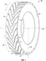
- Fig. 1 shows a tire 10 that is a heavy duty truck tire 10.
- the tire 10 is not designed for nor used with a car, motorcycle, or light truck (payload capacity less than 4,000 pounds), but is instead designed for and used with heavy duty trucks such as 18 wheelers, garbage trucks, or box trucks.
- the tire 10 may be a steer tire, a drive tire, a trailer tire, or an all position tire.
- the tire 10 includes a casing 92 onto which a tread 12 is disposed thereon.
- the tread 12 can be manufactured with the casing 92 and formed as a new tire 10, or the tread 12 can be a retread band that is attached to the casing 92 at some point after the casing 92 has already been used to form a retreaded tire 10.
- the central axis of the tire 10 extends through the center of the casing 92, and the lateral direction 28 of the tire 10 is parallel to the central axis.
- the radial direction 30, referred to also as the thickness direction 30, of the tire 10 is perpendicular to the central axis and the tread 12 is located farther from the central axis in the thickness direction 30 than the casing 92.
- the tread 12 extends all the way around the casing 92 in the circumferential direction 26, also referred to as the longitudinal direction 26, of the tire 10 and circles the central axis 360 degrees.
- the tread 12 includes a series of grooves and ribs that form a tread pattern.
- a rolling tread width 42 extends in the lateral direction 28 from one shoulder edge 72 of the tread 12, or an opposite shoulder edge 74 of the tread 12.
- the rolling tread width 42 represents that portion of the tread 12 that engages the ground through normal operation of the tire 10, and the shoulder edges 72, 74 may engage the ground as well as the area between these locations in the lateral direction 28.
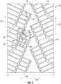
- Fig. 2 is a top view of a tread 12 that can be part of a tire 10 or a retread band that is produced and subsequently attached to a casing 92 to form a retread tire 10.
- the same tread pattern can repeat throughout the entire longitudinal length of the tread 12.
- the tread 12 has a tread groove 14 and additional tread grooves that are in sequence next to one another in the longitudinal direction 26.
- the tread grooves 14 can be variously shaped and have widths that can be greater than 2 millimeters.
- the shape of the center portion of the tread grooves 14 can be different than the shape of the shoulder portion of the tread grooves 14.
- a rib 76 is defined between the tread grooves in the longitudinal direction 26.
- the rib 76 is not a circumferential rib in that it does not extend all the way around the tread 12 in the longitudinal direction 26. Instead, the rib 76 extends from the shoulder edge 72 to the center of the tread 12. The rib 76 is angled relative to the longitudinal direction 26 so that the rib 76 extends so as to have a component of extension in both the longitudinal direction 26 and in the lateral direction 28. In contrast, a circumferential rib would have a component of extension in the longitudinal direction 26 and no component of extension in the lateral direction 28.
- the tread grooves 14 are likewise not circumferential grooves in that they extend so as to have a component of extension in both the longitudinal direction 26 and the lateral direction 28.
- the tread grooves 14 may extend from the shoulder edge 72 and terminate at some point at or near the center of the tread 12. In other embodiments, the tread grooves 14 and ribs 76 need not start at the shoulder edges 72, 74 and/or need not extend to the center.
- the tread grooves 14 may engage other grooves of the tread 12, and the ribs 76 may engage other ribs of the tread 12 in other arrangements.
- the tread grooves 14 and ribs 76 have different components in the longitudinal and lateral directions 26, 28 along their lengths and as shown in Fig. 2 change angles once.
- the tread grooves 14 and rib 76 can have the same components of lateral and longitudinal extensions along their entire lengths. This would result in the tread grooves 14 and ribs 76 being straight in shape although angled relative to the longitudinal direction 26. In other arrangements, the tread grooves 14 and rib 76 may curve or have two, three, four, or more angular changes along their lengths.
- the ribs 76 are located between the tread grooves 14 and can extend along to and terminate at the inboard most extensions of the tread grooves 14.
- the ribs 76 could also be thought of as terminating at a groove that the tread grooves 14 intersect near the center of the tread 12, but such an intersecting groove is not shown in Fig. 2 .
- the rib 76 may in some embodiments extend beyond the tread grooves 14 in the lateral and longitudinal directions 28, 26 until such time as the rib 76 terminates at the nearest groove, such as that shown in Fig. 2 .
- the rolling tread width 42 extends from the shoulder edge 72 to shoulder edge 74 in the lateral direction 28 and is the portion of the tread 12 that engages the ground during operations of the tire 10.
- the rib 76 extends a large amount in the lateral direction 28. With respect to the rolling tread width 42, the rib 76 extends at least 30% of the length of the rolling tread width 42 in the lateral direction 28. As such, the rib 76 extends across at least 30% of the width of the rolling tread width 42 of the tire 10. This rib 76 design thus distinguishes it from a block or other smaller feature proximate to the shoulder edge 72.
- the stone ejectors 24 could be located along the entire width of the tread 12 so that they are located at most or all of the lateral locations along the rolling tread width 42 and may be at the shoulder edges 72, 74. In other embodiments, the stone ejectors 24 are spaced from the shoulder edges 72, 74 so that they are closer to the center of the tread 12. In this regard, the stone ejectors 24 may not be located at all within 5% of the rolling tread width from the shoulder edge 72, and within 5% of the rolling tread width from the shoulder edge 74.
- the tread 12 is directional in that it is designed for forward rotation of the tire 10, but the tread 12 need not be directional in other exemplary embodiments.
- the rolling direction 32 is the direction in the longitudinal direction 26 the tread 12 is designed to rotate.
- the tread groove 14 extends into the tread 12 from an outer surface 16 of the tread 12 and includes a bottom surface 22 bounded on opposite sides by a leading edge wall 18 and a trailing edge wall 20.
- the leading edge wall 18 enters the contact patch of the tire 10 second as the tire 10 rotates in the rolling direction 32.
- the trailing edge wall 20 enters the contact patch of the tire 10 first before the leading edge wall 18.
- the bottom surface 22 may extend from the leading edge wall 18 to the trailing edge wall 20 and can open into the shoulder edge 72 and can terminate on its opposite end to the rubber of the tread 12.
- the tread 12 includes a stone ejector 24 that is used to help eject stones caught in the tread groove 14. Any number of the stone ejectors 24 can be present, and as shown in Fig. 2 a plurality of stone ejectors 24 are arranged on a linear segment of the tread groove 14. The stone ejectors 24 are located on the leading edge wall 18, and not the trailing edge wall 20. In some embodiments, all of the stone ejectors 24 in the tread groove 14 are located on the leading edge wall 18 or the trailing edge wall 20 such that the other wall 18, 20 does not include any of the stone ejectors 24.
- Placement of the stone ejectors 24 on the leading edge wall 18 has been observed by Applicants to provide the added benefit of reduction of abnormal wear of the tread 12.
- the stone ejectors 24 are instead placed onto the trailing edge wall 20 instead of the leading edge wall 18.
- other embodiments exit in which some of the tread grooves 14 include the stone ejectors 24 on the leading edge wall 18, while other ones of the tread grooves 14 include the stone ejectors 24 on the trailing edge wall 20.
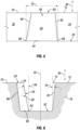
- Figs. 3-6 show various views of the tread groove 14 and the stone ejector 24 of Fig. 2 .
- the stone ejector 24 extends from the bottom surface 22 to a height in the thickness direction 30 that is the same height as the outer surface 16.
- the stone ejector 24 has a top surface 63 that is at the same location in the thickness direction 30 as the outer surface 16.
- the top surface 63 extends some amount in the lateral direction 28 to the outer surface 16.
- the engagement of the top surface 63 and the outer surface 16 may be indistinguishable in that they may be molded together with no parting line or other visible indicator of differentiation.
- the bottom surface 22 is flat but could be concave, convex, or have any other shape in other embodiments.
- the trailing edge wall 20 extends upwards in the thickness direction 30 from the bottom surface 22, and the trailing edge wall 20 is oriented at an angle X 54 to the thickness direction 30.
- the angle X 54 is 6 degrees in some embodiments, but can be from 0 to 30 degrees in other embodiments. Further, the angle X 54 may be negative in yet other embodiments so that the tread groove 14 is a closed or partially closed tread groove 14.
- the leading edge wall 18 may likewise be angled relative to the thickness direction 30 and its angle to the thickness direction 30 can be the same as the angle X 54, or may be different than the angle X 54 of the trailing edge wall 20.
- the stone ejector 24 features a front surface 56 that faces the trailing edge wall 20.
- the front surface 56 extends upwards in the thickness direction 30 from the bottom surface 22 to the top surface 63.
- the front surface 56 is oriented at an angle Y 58 to the thickness direction 30.
- the angle Y 58 may be 11 degrees in some embodiments, and in other embodiments may be from 5 degrees to 10 degrees, from 10 degrees to 15 degrees, from 15 degrees to 20 degrees, from 20 degrees to 30 degrees, or up to 45 degrees.
- the angle Y 58 is greater than the angle X 54. If the angle of the leading edge wall 18 is the same as angle X 54, the angle Y 58 of the front surface 56 is greater than both the angle X 54 and the angle of the leading edge wall 18.
- the stone ejector 24 has a right side surface 60 that extends from the bottom surface 22 to the top surface 63 in the thickness direction 30, and that extends from the front surface 56 to the leading edge wall 18.
- the stone ejector 24 also has a left side surface 62 that extends from the bottom surface 22 to the top surface 63, and from the front surface 56 to the leading edge wall 18.
- the right and left side surfaces 60, 62 have draft angles such that they are inclined relative to the thickness direction 30 such that they angle towards one another upon their extension from the bottom surface 22 to the top surface 63 in the thickness direction 30.
- the right and left side surfaces 60, 62 need not have these draft angles in other exemplary embodiments.
- the stone ejector 24 has a width 70 that extends from the right side surface 60 to the left side surface 62 and this width 70 may be measured along the length of extension of the tread groove 14.
- the width 70 may be the width of the front surface 56 in some embodiments.
- the stone ejector 24 can be arranged so that it does not extend beyond a centerline 50 of the tread groove 14 but instead remains on only one side of the centerline 50 or at most extends up to but not beyond the centerline 50. In other embodiments the stone ejector 24 may in fact go beyond the centerline 50. In the illustrated embodiment in Figs. 1-6 the stone ejector 24 is located completely on one side of the centerline 50.
- the centerline 50 is the midpoint of the tread groove 14 such that it is located an equal distance from the leading edge wall 18 and the trailing edge wall 20.
- the stone ejector 24 can have edges that are convex or concave in shape. As shown, the front surface 24 has a radius 64 between it and the bottom surface 22.
- the radius 64 extends from the right side surface 60 to the left side surface 62.
- the right side surface 60 has a radius 66 running along its engagement with the bottom surface 22 from the front surface 24 to the leading edge wall 18.
- the left side surface 62 has a radius 68 from the front surface 24 to the leading edge wall 18.
- the radii 64, 66, 68 can be of any size and in some embodiments are 2 millimeters. In other embodiments, the radii 64, 66, 68 are from 0.5 millimeters to 2 millimeters, from 2 millimeters to 3 millimeters, from 3 millimeters to 4 millimeters, or up to 5 millimeters.
- the stone ejector 24 also has radii at the engagement with the leading edge wall 18.
- the left side surface 62 has a radius 100 that extends from the bottom surface 22 to the top surface 63 and the radius 100 is at the leading edge wall 18.
- the right side surface 60 has a radius 98 at the leading edge wall 18 that runs from the bottom surface 22 to the top surface 63.
- the radii 98, 100 can be from 0.3 millimeters to 1 millimeter in some embodiments, and may be less than the radii 64, 66, 68.
- the radii 98, 100 may be from 1 millimeter to 2 millimeters, from 2 millimeters to 3 millimeters, from 3 millimeters to 4 millimeters, or up to 5 millimeters.
- the stone ejectors 24 may exist in which some or all of the radii and/or rounds are not present.
- the tread 12 in Fig. 2 includes a number of sipes 44 that extend from the outer surface 16 into the tread 12.
- the sipes 44 are shown as being linear is shape but can be variously shaped in other arrangements and have a width that is 2 millimeters or less.
- the sipes 44 have a width less than the tread grooves 14.
- the sipes 44 are arranged with respect to the stone ejectors 24 such that they do not engage the stone ejector 24 but are instead spaced therefrom.
- the sipes 44 engage the tread groove 14 by opening into the tread groove 14 and two of these engagement points are designated as engagement point 46 and engagement point 48 in Fig. 2 . There are numerous other engagement points with the other sipes 44 in Fig. 2 as well.
- the engagement points 46 and 48 are not located at the stone ejector 24 but rather spaced from the stone ejector 24 and on either side of the leading edge wall 18 with the stone ejector 24 between the two engagement points 46 and 48.
- the stone ejector 24 is thus located on the leading edge wall 18 at a spaced between and spaced from the adjacent sipes 44 that are located at engagement points 46 and 48 on either side and spaced from the stone ejector 24 along the leading edge wall 18.
- none of the sipes 44 engage any of the stone ejectors 24, and in yet other arrangements some or all of the stone ejectors 24 may be engaged by one or more of the sipes 44.
- the sipes 44 as shown do not touch the stone ejector 24 but are spaced completely from the right and left side walls 60, 62 and extend from the leading edge wall 18 to a subsequent tread groove that is identified as adjacent tread groove 96.
- the pair of sipes 44, the tread groove 14 and the adjacent tread groove 96 define a block 94 of the tread 12.
- the stone ejector 24 engages this block 94 and may be integrally formed therewith during the molding process of the tread 12.
- Various blocks 94 can be formed throughout the outer surface 16 and stone ejectors 24 can engage them, or not engage them depending upon the tread 12 design.
- the placement of the stone ejector 24 on the leading edge of the block 94 may increase the rigidity of the block 94 under loaded rolling and minimize kick-out stresses of the block 94. Placement of the stone ejectors 24 on the leading edge wall 18, as opposed to the trailing edge wall 20, may function to reduce block kick-out stresses. However, it is to be understood that other embodiments exist in which the stone ejectors 24 are put onto the trailing edge wall 20 and not the leading edge wall 18.
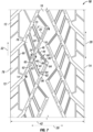
- Fig. 7 Another exemplary embodiment of the tread 12 is illustrated in Fig. 7 that again includes a plurality of stone ejectors 24 along the length of the leading edge walls 18.
- the sipes 44 are shown as being straight in shape with a generally rectangular cross-sectional shape, but can be wavy, curved, angled or variously shaped with various cross-sectional configurations in other exemplary embodiments.
- the geometry in the thickness direction 30 of the sipes 44 can also vary so that the sipes 44 have different cross-sectional shapes at different ones of their depth locations in the thickness direction 30.
- the sipes 44 could have different depths along their lengths or along the length of the rib 76 so as to be deeper or more shallow in the thickness direction 30 at various points.
- the sipes 44 are shown as extending all the way from the tread groove 14 to the adjacent tread groove 96, but in other embodiments some or all of them may not engage one or both of the grooves 14 and/or 96.
- the plurality of sipes 44 are arranged so that they do not have the same density across the rib 76.
- the density is the number of sipes 44 in a given area of the rib 76 such that some locations of the rib 76 have more sipes 44 than do other locations of the rib 44.
- the density can be defined by the distance that successive sipes 44 are from one another such that some sipes 44 are closer to other successive sipes 44, while other sipes 44 are farther from other successive sipes 44.
- the sipes 44 may be arranged so that there is a higher density of sipes 44 closer to the center of the tread 12 in the lateral direction 28 and so that there is a lower density of sipes farther from the center and thus closer to the shoulder edges 72, 74 in the lateral direction 28.
- the plurality of sipes 44 has a first sipe 82, a second sipe 84, and a third sipe 86 that are oriented so that the third sipe 86 is closer to the center of the tread 12 in the lateral direction 28 than the first and second sipes 82, 84 in the lateral direction 28.
- the second sipe 84 is located between the first sipe 82 and third sipe 86 along the angled rib 76.
- the geometry of the sipes 44 and the rib 76 may vary, in order to determine the distances between these features, one may measure the distance from the midpoint of the sipe 44 along its length of extension. In Fig.
- the sipes 82, 84, 86 are all oriented at angles to the grooves 14, 96 and the midpoints of the sipes 82, 84, 86 are each half way along their lengths from the tread groove 14 to the adjacent tread groove 96.
- the distance from the first sipe 82 to the second sipe 84 is denoted by reference number 88, and the distance 90 is the distance from the second sipe 84 to the third sipe 86.
- the distances 88, 90 are measured from the midpoints of the sipes 82, 84, 86 as measured upon their extension from the tread groove 14 to the adjacent tread groove 96.
- the distance 88 is greater by magnitude than the distance 90.
- the first, second, and third sipes 82, 84, 86 are successive such that the first sipe 82 is next to the second sipe 84 with no other sipes 44 there between, and the second sipe 84 is successive to the third sipe 86 so that no other sipes 44 are between the second and third sipes 84, 86.
- the distance 88 can be twice the size of distance 90, or may be only slightly greater in other embodiments.
- the arrangement of the three sipes 82, 84, 86 affords the rib 76 with sipes 44 that have different densities at different areas.
- the minimum amount of sipes 44 is three in the rib 76, but any number can be present in other embodiments. If extra numbers of sipes 76 are present then they can be spaced all the same from successive sipes 44 or may be spaced different distances from successive sipes 44.
- the tread 12 is shown with sipes 44, it is to be understood that no sipes 44 are present in other versions of the tread 12, and that the tread 12 need not have variable density sipes 44 in other embodiments.
- the tread 12 also includes other features besides the stone ejectors 24 such as a shoulder block 78 that begins at, and is bounded by, the shoulder edge 72.
- the leading edge of the shoulder block 78 is defined by the tread groove 14.
- the trailing edge of the shoulder block 78 is defined by the adjacent tread groove 96.
- the shoulder block 78 is defined by a decouple groove 80.
- the shoulder block 78 is located adjacent the rib 76 such that the rib 76 begins at and is bounded on its lateral outboard side by the decouple groove 80.
- the shoulder block 78 width may be 5%, 10%, 15%, or up to 20% of the rolling tread width 42, which are percentages of the width of the tread 12 from the shoulder edge 72 to shoulder edge 74 in the lateral direction 28.
- the decouple groove 80 has a width that is less than the width of the tread groove 14. The widths can be the same across the lengths of these grooves 14, 80 or vary. If they vary, the widths can be calculated in any manner. For instance, the width can be the average of taking twenty evenly spaced locations along the lengths of the tread grooves 14 and decouple grooves 80.
- the decouple groove 80 is oriented more in the longitudinal direction 26 than in the lateral direction 28.
- the decouple groove 80 may extend at least twice as long in the longitudinal direction 26 than in the lateral direction 28.
- the decouple groove 80 is primarily linear in shape but angles at its trailing end to engage the adjacent tread groove 96. There are two sipes 44 shown in the tread block 44 that engage the shoulder edge 72 and the decouple groove 80
- the shoulder block 78, rib 76, decouple groove 80, tread groove 14 and adjacent tread groove 96 can be repeated across the entire tread 12 and in addition to being associated with the shoulder edge 72 can extend from and be associated with the shoulder edge 74.
- These elements can be the same as one another or may be different, and can be arranged as previously discussed so a repeat of this information is not necessary. As such, it is to be understood that the described elements of the tread 12 herein need not be located at just one particular location but can be at any area or location on the tread 12. Decoupling of the shoulder block 78 by the decouple groove 80 reduces or eliminates abnormal wear that may be present in the shoulder block 78 through the arrangements of the tread grooves 14 and rib 76.
- Shoulder block 78 protects the interior portion of the rib 76 which would be the portion of the rib 76 inboard from the shoulder block 78 in the lateral direction 28.
- the shoulder block 78 will react differently to forces imparted thereon with the presence of the decouple groove 80 and will cause the adjacent portion of rib 76 to wear more evenly.
- a shoulder block 78 and decouple groove 80 it is to be understood that these features of the tread 12 are optional and, along with the variable sipe density feature previously discussed, may or may not be incorporated into designs of the tread 12 that include the stone ejectors 24.
- the design of the stone ejectors 24 in Figs. 7-9 is different than those previously discussed.
- the stone ejectors 24 do not have a top surface 63 but rather the front surface 56 extends up to and engages the outer surface 16 without forming the top surface 63.
- the front surface 56 extends across the width of the tread groove 14 to the centerline 50 but does not cross the centerline 50.
- the radius 64 is located at the centerline 50 and is the portion of the stone ejector 24 farthest from the leading edge wall 18. Similarities exist, for example Angle Y 58 is greater than angle X 54. In some embodiments the angle X 54 may be from 4-8 degrees, and the angle Y 58 may be from 30-50 degrees.
- the angle X 54 is 6 degrees, and the angle Y 58 is 11 degrees.
- the angle Y 58 may be 1 degree, from 1-5 degrees, from 5-10 degrees, from 10-15 degrees, from 15-20 degrees, from 20-25 degrees, from 25-30 degrees, from 30-35 degrees, from 35-40 degrees, from 40-45 degrees, from 1-10 degrees, from 10-20 degrees, from 20-30 degrees, from 30-45 degrees, or from 25-35 degrees.
- the angle X 54 may be the same as the angle of the leading edge wall 18 to the thickness direction 30.
- the sipes 44 do not engage the stone ejectors 24, and as shown a pair of sipes 44 are located between some of the successive stone ejectors 24 such that this pair of sipes 44 engage the tread groove 14 at locations between the successive stone ejectors 24.
- the stone ejectors 24 in the tread groove 14 differ from one another in that successive stone ejectors 24 are wider or narrower. With reference in particular to Fig. 8 , the stone ejector 24 closest to the center has a width 70 that is greater than the stone ejector 24 immediately next to it.
- each stone ejector 24 approaching the shoulder edge 72 has a smaller width 70 than the one previous.
- successive stone ejectors 24 may have the same width.
- the stone ejectors 24 are arranged so that their widths 70 increase upon moving towards the shoulder edge 72, 74.
- having larger widths 70 closer to the center and then smaller widths 70 closer to the shoulder edges 72, 74 may allow water in the tread groove 14 to more easily be drained out of the shoulder edges 72, 74. It is to be understood that the widths 70 need not always be increasing or decreasing between successive stone ejectors 24.
- 2 or more successive stone ejectors 24 could have the same width 70 and then the next stone ejector 24 could have a different width 70.
- zones of stone ejectors 24 successive to one another can have the same width 70 and adjacent zones of stone ejectors 24 could have a different width 70.
- the widths 70 could be provided in any combination in the series of stone ejectors 24 in the tread groove 14.
- the stone ejectors 24 can be arranged in a variety of manners in accordance with different exemplary embodiments of the tread 12.
- Fig. 10 shows another exemplary embodiment similar to the Figs. 7-10 embodiment in which the top surfaces 63 are not present and the front face 56 extends from the bottom surface 22 to the outer surface 16.
- the right and left side surfaces 60, 62 are angled relative to the front surface 56 and the widths 70 could be measured from the widest point defined between the right and left side surfaces 60, 62.
- the extensions of all of the stone ejectors 24 into the bottom surface 22 are similar such that the radii 64 are all located an equal distance from the leading edge wall 18.
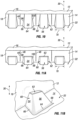
- Fig. 11A is another embodiment that has stone ejectors 24 similar to those of Fig. 10 but having top surfaces 63 on all of the stone ejectors 24 such that none of the stone ejectors 24 extend to the outer surface 16.
- the top surfaces 63 can be flat and are all spaced a distance from the top surface 63 in the thickness direction 30.
- the widths 70 of all of the stone ejectors 24 are the same.
- a perspective view of one of the stone ejectors 24 is shown in Fig. 11B and it can be seen that a round is present between the right side surface 60 and the front surface 56. Although not entirely visible in the figure another round is present between the front surface 56 and the left side surface 62. Radii 64, 66 and 68 are all present as well. Further, rounds can be present between the top surface 63 and the front and side surfaces 56, 60, 62.
- FIG. 12 Another embodiment of the stone ejector 24 is illustrated in Fig. 12 in which the plurality of stone ejectors 24 again extend all the way up to the outer surface 16 such that a top surface 63 is not present thus having the front surface 56 extend completely from the bottom surface 22 to outer surface 16. Radii and rounds are not present in this arrangement, but the stone ejectors 24 could have them in other versions of the tread 12. Successive stone ejectors 24 are arranged so that the distance from the bottom of the front face 56 to the leading edge wall 18 changes from one stone ejector 24 to the next. In this regard, the stone ejector 24 on the left hand side of Fig.
- the stone ejector 24 on the right hand side of Fig. 12 extends the greatest amount into the tread groove 14 and thus is closer to the centerline 50 than any of the other stone ejectors 24.
- the stone ejectors 24 having the greatest extension into the tread groove 14 may be located closer to the center of the tread groove 14 and those extending the least closer to one of the shoulder edges 72, 74 so that water may be more easily removed from the tread groove 14, but it is to be understood that this could be reversed in other embodiments.
- the angle Y 58 will be different as per each successive stone ejector 24 since the front surface 56 is angled differently depending upon how far out into the tread groove 14 it extends. All of the stone ejectors 24 can be arranged so that each successive one increases or decreases extension into the tread groove 14 and none of them have the same amount of extension. However, it may be envisioned that in other embodiments some of the stone ejectors 24 have the same extension, and in other embodiments successive ones increase into the tread groove 14 and then decrease in extension into the tread groove 14.
- the angle Y 56 may increase/decrease for every successive front surface 56 in the tread groove 14 so that each one of the stone ejectors 24 has a different magnitude of angle Y 56, or the angle Y 56 could be common among one or more of the front surfaces 56 of the stone ejectors 24 in the tread groove 14.
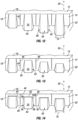
- FIG. 13 Another exemplary embodiment of the tread 12 is shown in Fig. 13 in which the top surfaces 63 are again not present.
- the stone ejectors 24 extend at different amounts into the tread groove 14, that is different amounts away from the leading edge wall 18, so that each successive stone ejector 24 is a different amount away and no two stone ejectors 24 extend the same amount into the tread groove 14.
- This embodiment is different than the others in that the stone ejector 24 closest to the leading edge wall 18 extends to the outer surface 16, but no other stone ejectors 24 extend thereto.
- the remaining stone ejectors 24 are spaced a distance from the outer surface 16 in the thickness direction 30.
- the angle Y 56 of each stone ejector 24 can be different so that no two stone ejectors 24 in the tread groove 14 have the same magnitude of angle Y 56.
- the Fig. 14 embodiment of the tread 12 includes stone ejectors 24 in the tread groove 14 that all have top surfaces 63 and that all stop short of the outer surface 16 so that all of the top surfaces 63 are spaced a distance from the outer surface 16 in the thickness direction 30.
- the distances of extension of the stone ejectors 24 into the tread groove 14 are also all varied so that successive ones are either longer or shorter distances into the tread groove 14 towards the centerline 50.
- numerous variations of the stone ejectors 24 are possible as described, and features of one embodiment can be incorporated into another to yield a third embodiment.
- the changing widths 70 of the stone ejectors of the Figs. 7-9 embodiment can be incorporated into the Fig. 14 embodiment to yield an embodiment where the widths 70 of successive stone ejectors 24 increase/decrease along with increasing/decreasing extensions of the stone ejectors 24 into the tread groove 14.
- Fig. 15 shows an alternate embodiment of the tread 12 in which grooves 104 are present, it being understood that no grooves other than the tread grooves 14 were present in the tread 12 in previously illustrated and described embodiments.
- Fig. 15 shows in further detail two stone ejectors 24 of one embodiment that are located on and extend from the leading edge wall 18.
- the trailing edge wall 20 is opposite the leading edge wall 18 and the stone ejectors 24 do not engage this opposite trailing edge wall 20. However, the stone ejectors 24 do face the opposite trailing edge wall 20.
- One of the illustrated stone ejectors has a top surface 63 but only two side surfaces designated as the left side surface 62 and the front surface 56, with no right side surface 60.
- a width 102 of the stone ejector 24 is the distance along the leading edge wall 18 that the stone ejector 24 extends, and may be the width 70 in other exemplary embodiments. The width 102 is translated to the opposite trailing edge wall 20 as denoted.
- the extension of the width 102 to the trailing edge wall 20 is made so as to be at a ninety degree angle to the centerline 50.
- the width 102 as placed onto the trailing edge wall 20 does not engage any grooves 104 of the tread 12 and in the embodiment shown does not engage any sipes 44 of the tread 12.
- the second illustrated stone ejector 24 has a top surface 63, front surface 56, right side surface 60, and left side surface 62.
- the width 102 of the second stone ejector 24 in Fig. 15 is the maximum extension of the second stone ejector 24 along the leading edge wall 18.
- the width 102 is extended to the opposite trailing edge wall 20 and there is no groove 104 engaging this extended width 102 on the trailing edge wall 20.
- the tread 12 is arranged so that none of the widths 102 of the stone ejectors 24 projected onto the opposite wall when done so encompass a groove 104 or a sipe 44 of the tread 12.
- the stone ejectors 24 of the Figs. 2 and 7 embodiments face the trailing edge grooves 20 so that their widths 102 do not encompass any grooves or sipes 44.
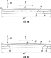
- a typical heavy truck tire 10 with longitudinal grooves would have an average void depth 34 curve that contains portions extending from the tire tread 12 outer surface 16 to beyond 60% of the full void depth.
- a twenty percent line 36 and a sixty percent line 38 are illustrated and denote the location in the thickness direction 30 in which twenty percent of the thickness direction 30 height of the tread 12 would otherwise be removed from the outer surface, and in which sixty percent of the thickness direction 30 height of the tread 12 would otherwise be removed from the outer surface 16.
- the full void depth 40 is the distance from the outer surface 16 to a curve that is transposed in the thickness direction 30 from the outer surface 16 of tread 12 by a distance equal to the deepest point of the void of the tread 12.
- the twenty percent line 36 is twenty percent of the full void depth 40 down from the outer surface 16, and the sixty percent line 38 is sixty percent of the full void depth 40 down from the outer surface 16.
- the average void depth 34 is shown and the twenty and sixty percent lines 36, 38 are also present for reference.
- the tread 12 has four longitudinal grooves that extend around the entire circumference of the tread 12 in the longitudinal direction 26 and these four grooves are illustrated as the four greatest depressions, grooves in the average void depth 34.
- the average void depth 34 thus has portions that go past the twenty percent line 36 and that likewise go past the sixty percent line 38.
- a heavy truck steer tire 10 would have an average void depth 34 curve that greatly resembles the tire tread 12 and thus the longitudinal groove shapes.
- a typical heavy truck drive tire with longitudinal grooves and tread blocks would have an average void depth 34 curve similar to the steer tire example but with portions that are close to the tread 12 outer surface 16. This is because the tread blocks contain lateral grooves which increase the average depth around the tire.
- a drive tire may have longitudinal grooves that have a wavy or zig-zag shape, thus some component in the lateral direction 28. Nevertheless the average void depth 34 curve will still have a portion or portions that extend beyond 60% of the full void depth 40.
- Fig. 17 shows an average void depth 34 for a tread 12 that has angled tread grooves 14 and ribs 76.
- a heavy truck tire 10 with the angled tread grooves 14 and ribs 76 has an average void depth 34 curve that is relatively flat and does not extend more than 20% of the full void depth 40. As such, the average void depth 34 does not go past the twenty percent line 36.
- the tread 12 includes one or more decoupled grooves 80, then the average void depth 34 would extend past the twenty percent line 36.
- Decoupled grooves 80 are grooves that extend primarily in the longitudinal direction 26 and function to decouple a shoulder block 78 of the tread 12 from an adjacent rib or other feature as discussed.
- decouple grooves 80 on either side of the tread 12 to decouple the shoulder blocks 78 on either side of the tread 12.
- the decouple grooves 80 do not count for purposes of the average void depth 34 going past the twenty percent line 36 and thus are ignored in Fig. 17 .
- the average void depth 34 does not include decouple grooves 80.
- the average void depth 34 outboard of the two decoupled grooves 80 to the tread edges in the lateral direction 28 could likewise extend past the twenty percent line 36 due to openings being present in the tread 12 at these locations.
- the rest of the average void depth 34 as shown in Fig. 17 does not go past the twenty percent line 36.
- large openings may be present at and extending inboard from the shoulder edges 72 and 74 which may thus function to cause the average void depth 34 to go below the twenty percent line 36 when measured.
- the average void depth 34 is measured from one decoupling groove 80 to the other in the lateral direction 28, and the average void depth 34 at the decoupling grooves 80 and of the tread 12 outboard of the decoupling grooves 80 in the lateral direction 28 are not counted.
- the decoupling grooves 80 are positioned next to shoulder edges 72, 74 and are thus generally disposed on opposite sides of the tread 10 in the lateral direction 28.
- the "outboard" portion of the tread 10 are those portions of the tread 10 immediately adjacent the decoupling grooves 80 and extending outboard in the lateral direction 28.
- the outboard portion of the tread 10 from one of the decoupling grooves 80 is the shoulder bock 78 defined by that particular decoupling groove 80 or portions of the tread 10 right next to and outboard of the decoupling groove 80 and not across the centerline of the tread 10 in the lateral direction 28.
- the description of the tread 10 with respect to the average void depth 34 can also be defined in another manner.
- the tread 10 can have a centerline in the lateral direction 28, which in effect splits the tread 10 up into a left half and a right half.
- the average void depth 34 of the tread 10 does not go past the twenty percent line 36 inboard from the decouple groove 80 in the lateral direction 28 to the centerline.
- the average void depth 34 could go past the twenty percent line 36 at the decouple groove 80 and/or outboard of the decouple groove 80 in the lateral direction 28 to the shoulder edge 72 or 74 (depending on which side of the tread 10 the decouple groove 80 is positioned).
- the average void depth 34 inboard of the decouple grooves 80 does not go past the twenty percent line 36, while the average void depth 34 at and/or outboard of the decouple grooves 80 may or may not go past the twenty percent line 36.
Landscapes
- Engineering & Computer Science (AREA)
- Mechanical Engineering (AREA)
- Tires In General (AREA)
Description
- The subject matter of the present invention relates to a truck tire that has reduced abnormal tread wear. More particularly, the present application involves a truck tire tread that features an angled rib with stone ejectors in tread grooves on one side of the tread grooves.
- Manufacturers of heavy commercial vehicle tires have made huge progress in developing tire architectures and tire materials that allow them to increase the wear resistance of tire treads and reduce the rolling resistance of tires while at the same time improving their level of grip and resistance to road hazard. Tread patterns may include a series of circumferential grooves between which a series of circumferential ribs are positioned. The circumferential direction, which can also be described as the longitudinal direction, extends around the central axis of the tire and is oriented at a ninety degree angle to the lateral direction of the tire. The circumferential grooves and ribs extend 360 degrees around the tire and are oriented so that they have a component of extension in the longitudinal/circumferential direction but no component of extension in the lateral direction. A variation of tread patterns involves orienting the ribs and grooves so that they are not circumferential ribs and grooves, but rather include a component of extension in the lateral direction. In this regard, the tread grooves and ribs can extend from the shoulder edges inward in the lateral direction while at the same time extending some amount in the longitudinal direction to result in an "angled" orientation of these tread features.
- The use of angled ribs and grooves achieves some advantages over tread designs that include only circumferential grooves and ribs. Designs with angled grooves and ribs introduce directionality into the tire. The use of angled ribs and grooves has been shown to prevent the retention of stones within the tread grooves and to subsequently reduce stone drilling, which is the pushing of the stone into the rubber of the tread. It is known to provide stone ejectors within tread grooves that function to reduce penetration of pointed and sharp rocks caught in the tread and thus reduce stone drilling. However, the use of angled grooves and ribs may result in kick-out stresses that could wear down the tread. As the combination of angled grooves and ribs and stone ejectors is not common, variation and improvement within the art is desired to optimize the performance of the stone ejectors within the tread grooves and potentially to minimize kick-out stresses on the tread.
- The document
WO 2017/116706 A discloses a heavy truck tire tread. - The present invention provides a heavy truck tire tread as defined in claim 1.
- A full and enabling disclosure of the present invention, including the best mode thereof, directed to one of ordinary skill in the art, is set forth in the specification, which makes reference to the appended figures, in which:
-
Fig. 1 is a perspective view of a heavy truck tire. -
Fig. 2 is top view of tread in accordance with one exemplary embodiment. -
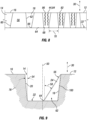
Fig. 3 is cross-sectional view taken along line 3-3 inFig. 2 . -
Fig. 4 is a cross-sectional view taken along line 4-4 inFig. 2 . -
Fig. 5 is a cross-sectional view taken along line 5-5 inFig. 2 . -
Fig. 6 is a cross-sectional view taken along line 6-6 inFig. 2 . -
Fig. 7 is a top view of tread in accordance with another exemplary embodiment. -
Fig. 8 is a view taken along line 8-8 ofFig. 7 . -
Fig. 9 is a cross-sectional view taken along line 9-9 inFig. 7 . -
Fig. 10 is a front perspective view of a plurality of stone ejectors in a tread groove in accordance with another exemplary embodiment. -
Fig. 11A is a front perspective view of a plurality of stone ejectors in a tread groove in accordance with another exemplary embodiment. -
Fig. 11B is a perspective view of one of the stone ejectors ofFig. 11A . -
Fig. 12 is a front perspective view of a plurality of stone ejectors in a tread groove in accordance with another exemplary embodiment. -
Fig. 13 is a front perspective view of a plurality of stone ejectors in a tread groove in accordance with another exemplary embodiment. -
Fig. 14 is a front perspective view of a plurality of stone ejectors in a tread groove in accordance with another exemplary embodiment. -
Fig. 15 is a top view of a section of a tread groove and two stone ejectors. -
Fig. 16 is a graph of the average void depth for a tire that has four longitudinal grooves about its circumference with no angled grooves or ribs. -
Fig. 17 is a graph of the average void depth for a tire that has angled grooves and ribs and a pair of decoupled grooves. - The use of identical or similar reference numerals in different figures denotes identical or similar features.
- Reference will now be made in detail to embodiments of the invention, one or more examples of which are illustrated in the drawings. Each example is provided by way of explanation of the invention, and not meant as a limitation of the invention. For example, features illustrated or described as part of one embodiment can be used with another embodiment to yield still a third embodiment. It is intended that the present invention include these and other modifications and variations.
- The present invention provides for a
tread 12 for a heavyduty truck tire 10 that has atread groove 14 that is not oriented completely in alongitudinal direction 26 or alateral direction 28. Astone ejector 24 is in thetread groove 14 and engages either a leadingedge wall 18 of thetread groove 14 or atrailing edge wall 20 of thetread groove 14, but not both. Thestone ejector 24 faces thewall stone ejectors 24 in highangled tread groove 14 imparts traction to thetread 12 and minimizes block kick-out stresses, and provides protection against stone drilling and reduces irregular wear of thetread 12. -
Fig. 1 shows atire 10 that is a heavyduty truck tire 10. In this regard, thetire 10 is not designed for nor used with a car, motorcycle, or light truck (payload capacity less than 4,000 pounds), but is instead designed for and used with heavy duty trucks such as 18 wheelers, garbage trucks, or box trucks. Thetire 10 may be a steer tire, a drive tire, a trailer tire, or an all position tire. Thetire 10 includes acasing 92 onto which atread 12 is disposed thereon. Thetread 12 can be manufactured with thecasing 92 and formed as anew tire 10, or thetread 12 can be a retread band that is attached to thecasing 92 at some point after thecasing 92 has already been used to form a retreadedtire 10. This is the case with all of the designs shown and described herein. They may all be tread designs of a brandnew tire 10, or may be tread designs of atread 12 for use in aretread tire 10. The central axis of thetire 10 extends through the center of thecasing 92, and thelateral direction 28 of thetire 10 is parallel to the central axis. Theradial direction 30, referred to also as thethickness direction 30, of thetire 10 is perpendicular to the central axis and thetread 12 is located farther from the central axis in thethickness direction 30 than thecasing 92. Thetread 12 extends all the way around thecasing 92 in thecircumferential direction 26, also referred to as thelongitudinal direction 26, of thetire 10 and circles the central axis 360 degrees. Thetread 12 includes a series of grooves and ribs that form a tread pattern. Arolling tread width 42 extends in thelateral direction 28 from oneshoulder edge 72 of thetread 12, or anopposite shoulder edge 74 of thetread 12. Therolling tread width 42 represents that portion of thetread 12 that engages the ground through normal operation of thetire 10, and theshoulder edges lateral direction 28. -
Fig. 2 is a top view of atread 12 that can be part of atire 10 or a retread band that is produced and subsequently attached to acasing 92 to form aretread tire 10. The same tread pattern can repeat throughout the entire longitudinal length of thetread 12. Thetread 12 has atread groove 14 and additional tread grooves that are in sequence next to one another in thelongitudinal direction 26. Thetread grooves 14 can be variously shaped and have widths that can be greater than 2 millimeters. The shape of the center portion of thetread grooves 14 can be different than the shape of the shoulder portion of thetread grooves 14. Arib 76 is defined between the tread grooves in thelongitudinal direction 26. Therib 76 is not a circumferential rib in that it does not extend all the way around thetread 12 in thelongitudinal direction 26. Instead, therib 76 extends from theshoulder edge 72 to the center of thetread 12. Therib 76 is angled relative to thelongitudinal direction 26 so that therib 76 extends so as to have a component of extension in both thelongitudinal direction 26 and in thelateral direction 28. In contrast, a circumferential rib would have a component of extension in thelongitudinal direction 26 and no component of extension in thelateral direction 28. - The
tread grooves 14 are likewise not circumferential grooves in that they extend so as to have a component of extension in both thelongitudinal direction 26 and thelateral direction 28. Thetread grooves 14 may extend from theshoulder edge 72 and terminate at some point at or near the center of thetread 12. In other embodiments, thetread grooves 14 andribs 76 need not start at the shoulder edges 72, 74 and/or need not extend to the center. Thetread grooves 14 may engage other grooves of thetread 12, and theribs 76 may engage other ribs of thetread 12 in other arrangements. Thetread grooves 14 andribs 76 have different components in the longitudinal andlateral directions Fig. 2 change angles once. In other embodiments, thetread grooves 14 andrib 76 can have the same components of lateral and longitudinal extensions along their entire lengths. This would result in thetread grooves 14 andribs 76 being straight in shape although angled relative to thelongitudinal direction 26. In other arrangements, thetread grooves 14 andrib 76 may curve or have two, three, four, or more angular changes along their lengths. - The
ribs 76 are located between thetread grooves 14 and can extend along to and terminate at the inboard most extensions of thetread grooves 14. Theribs 76 could also be thought of as terminating at a groove that thetread grooves 14 intersect near the center of thetread 12, but such an intersecting groove is not shown inFig. 2 . Further, therib 76 may in some embodiments extend beyond thetread grooves 14 in the lateral andlongitudinal directions rib 76 terminates at the nearest groove, such as that shown inFig. 2 . - The rolling
tread width 42 extends from theshoulder edge 72 toshoulder edge 74 in thelateral direction 28 and is the portion of thetread 12 that engages the ground during operations of thetire 10. Therib 76 extends a large amount in thelateral direction 28. With respect to the rollingtread width 42, therib 76 extends at least 30% of the length of the rollingtread width 42 in thelateral direction 28. As such, therib 76 extends across at least 30% of the width of the rollingtread width 42 of thetire 10. Thisrib 76 design thus distinguishes it from a block or other smaller feature proximate to theshoulder edge 72. The stone ejectors 24 could be located along the entire width of thetread 12 so that they are located at most or all of the lateral locations along the rollingtread width 42 and may be at the shoulder edges 72, 74. In other embodiments, thestone ejectors 24 are spaced from the shoulder edges 72, 74 so that they are closer to the center of thetread 12. In this regard, thestone ejectors 24 may not be located at all within 5% of the rolling tread width from theshoulder edge 72, and within 5% of the rolling tread width from theshoulder edge 74. - The
tread 12 is directional in that it is designed for forward rotation of thetire 10, but thetread 12 need not be directional in other exemplary embodiments. The rollingdirection 32 is the direction in thelongitudinal direction 26 thetread 12 is designed to rotate. Thetread groove 14 extends into thetread 12 from anouter surface 16 of thetread 12 and includes abottom surface 22 bounded on opposite sides by aleading edge wall 18 and a trailingedge wall 20. Theleading edge wall 18 enters the contact patch of thetire 10 second as thetire 10 rotates in the rollingdirection 32. The trailingedge wall 20 enters the contact patch of thetire 10 first before theleading edge wall 18. Thebottom surface 22 may extend from the leadingedge wall 18 to the trailingedge wall 20 and can open into theshoulder edge 72 and can terminate on its opposite end to the rubber of thetread 12. Thetread 12 includes astone ejector 24 that is used to help eject stones caught in thetread groove 14. Any number of thestone ejectors 24 can be present, and as shown inFig. 2 a plurality ofstone ejectors 24 are arranged on a linear segment of thetread groove 14. The stone ejectors 24 are located on theleading edge wall 18, and not the trailingedge wall 20. In some embodiments, all of thestone ejectors 24 in thetread groove 14 are located on theleading edge wall 18 or the trailingedge wall 20 such that theother wall stone ejectors 24. Placement of thestone ejectors 24 on theleading edge wall 18 has been observed by Applicants to provide the added benefit of reduction of abnormal wear of thetread 12. However, it is to be understood that other embodiments exist in which thestone ejectors 24 are instead placed onto the trailingedge wall 20 instead of theleading edge wall 18. Also, other embodiments exit in which some of thetread grooves 14 include thestone ejectors 24 on theleading edge wall 18, while other ones of thetread grooves 14 include thestone ejectors 24 on the trailingedge wall 20. -
Figs. 3-6 show various views of thetread groove 14 and thestone ejector 24 ofFig. 2 . Thestone ejector 24 extends from thebottom surface 22 to a height in thethickness direction 30 that is the same height as theouter surface 16. Thestone ejector 24 has atop surface 63 that is at the same location in thethickness direction 30 as theouter surface 16. Thetop surface 63 extends some amount in thelateral direction 28 to theouter surface 16. The engagement of thetop surface 63 and theouter surface 16 may be indistinguishable in that they may be molded together with no parting line or other visible indicator of differentiation. Thebottom surface 22 is flat but could be concave, convex, or have any other shape in other embodiments. The trailingedge wall 20 extends upwards in thethickness direction 30 from thebottom surface 22, and the trailingedge wall 20 is oriented at anangle X 54 to thethickness direction 30. Theangle X 54 is 6 degrees in some embodiments, but can be from 0 to 30 degrees in other embodiments. Further, theangle X 54 may be negative in yet other embodiments so that thetread groove 14 is a closed or partiallyclosed tread groove 14. Theleading edge wall 18 may likewise be angled relative to thethickness direction 30 and its angle to thethickness direction 30 can be the same as theangle X 54, or may be different than theangle X 54 of the trailingedge wall 20. - The
stone ejector 24 features afront surface 56 that faces the trailingedge wall 20. Thefront surface 56 extends upwards in thethickness direction 30 from thebottom surface 22 to thetop surface 63. Thefront surface 56 is oriented at anangle Y 58 to thethickness direction 30. Theangle Y 58 may be 11 degrees in some embodiments, and in other embodiments may be from 5 degrees to 10 degrees, from 10 degrees to 15 degrees, from 15 degrees to 20 degrees, from 20 degrees to 30 degrees, or up to 45 degrees. Theangle Y 58 is greater than theangle X 54. If the angle of theleading edge wall 18 is the same asangle X 54, theangle Y 58 of thefront surface 56 is greater than both the angle X 54 and the angle of theleading edge wall 18. - The
stone ejector 24 has aright side surface 60 that extends from thebottom surface 22 to thetop surface 63 in thethickness direction 30, and that extends from thefront surface 56 to theleading edge wall 18. Thestone ejector 24 also has aleft side surface 62 that extends from thebottom surface 22 to thetop surface 63, and from thefront surface 56 to theleading edge wall 18. As shown more clearly inFig. 5 , the right and left side surfaces 60, 62 have draft angles such that they are inclined relative to thethickness direction 30 such that they angle towards one another upon their extension from thebottom surface 22 to thetop surface 63 in thethickness direction 30. The right and left side surfaces 60, 62 need not have these draft angles in other exemplary embodiments. Thestone ejector 24 has awidth 70 that extends from theright side surface 60 to theleft side surface 62 and thiswidth 70 may be measured along the length of extension of thetread groove 14. Thewidth 70 may be the width of thefront surface 56 in some embodiments. - The
stone ejector 24 can be arranged so that it does not extend beyond acenterline 50 of thetread groove 14 but instead remains on only one side of thecenterline 50 or at most extends up to but not beyond thecenterline 50. In other embodiments thestone ejector 24 may in fact go beyond thecenterline 50. In the illustrated embodiment inFigs. 1-6 thestone ejector 24 is located completely on one side of thecenterline 50. Thecenterline 50 is the midpoint of thetread groove 14 such that it is located an equal distance from the leadingedge wall 18 and the trailingedge wall 20. Thestone ejector 24 can have edges that are convex or concave in shape. As shown, thefront surface 24 has aradius 64 between it and thebottom surface 22. Theradius 64 extends from theright side surface 60 to theleft side surface 62. Theright side surface 60 has aradius 66 running along its engagement with thebottom surface 22 from thefront surface 24 to theleading edge wall 18. In a similar vein, theleft side surface 62 has aradius 68 from thefront surface 24 to theleading edge wall 18. Theradii radii stone ejector 24 also has radii at the engagement with theleading edge wall 18. Theleft side surface 62 has aradius 100 that extends from thebottom surface 22 to thetop surface 63 and theradius 100 is at theleading edge wall 18. Theright side surface 60 has aradius 98 at theleading edge wall 18 that runs from thebottom surface 22 to thetop surface 63. Theradii radii radii stone ejectors 24 exist in which some or all of the radii and/or rounds are not present. - The
tread 12 inFig. 2 includes a number ofsipes 44 that extend from theouter surface 16 into thetread 12. Thesipes 44 are shown as being linear is shape but can be variously shaped in other arrangements and have a width that is 2 millimeters or less. Thesipes 44 have a width less than thetread grooves 14. Thesipes 44 are arranged with respect to thestone ejectors 24 such that they do not engage thestone ejector 24 but are instead spaced therefrom. Thesipes 44 engage thetread groove 14 by opening into thetread groove 14 and two of these engagement points are designated asengagement point 46 andengagement point 48 inFig. 2 . There are numerous other engagement points with theother sipes 44 inFig. 2 as well. The engagement points 46 and 48 are not located at thestone ejector 24 but rather spaced from thestone ejector 24 and on either side of theleading edge wall 18 with thestone ejector 24 between the twoengagement points stone ejector 24 is thus located on theleading edge wall 18 at a spaced between and spaced from theadjacent sipes 44 that are located at engagement points 46 and 48 on either side and spaced from thestone ejector 24 along the leadingedge wall 18. In some embodiments, none of thesipes 44 engage any of thestone ejectors 24, and in yet other arrangements some or all of thestone ejectors 24 may be engaged by one or more of thesipes 44. Thesipes 44 as shown do not touch thestone ejector 24 but are spaced completely from the right and leftside walls edge wall 18 to a subsequent tread groove that is identified asadjacent tread groove 96. The pair ofsipes 44, thetread groove 14 and theadjacent tread groove 96 define ablock 94 of thetread 12. Thestone ejector 24 engages thisblock 94 and may be integrally formed therewith during the molding process of thetread 12.Various blocks 94 can be formed throughout theouter surface 16 andstone ejectors 24 can engage them, or not engage them depending upon thetread 12 design. The placement of thestone ejector 24 on the leading edge of theblock 94 may increase the rigidity of theblock 94 under loaded rolling and minimize kick-out stresses of theblock 94. Placement of thestone ejectors 24 on theleading edge wall 18, as opposed to the trailingedge wall 20, may function to reduce block kick-out stresses. However, it is to be understood that other embodiments exist in which thestone ejectors 24 are put onto the trailingedge wall 20 and not theleading edge wall 18. - Another exemplary embodiment of the
tread 12 is illustrated inFig. 7 that again includes a plurality ofstone ejectors 24 along the length of theleading edge walls 18. Thesipes 44 are shown as being straight in shape with a generally rectangular cross-sectional shape, but can be wavy, curved, angled or variously shaped with various cross-sectional configurations in other exemplary embodiments. The geometry in thethickness direction 30 of thesipes 44 can also vary so that thesipes 44 have different cross-sectional shapes at different ones of their depth locations in thethickness direction 30. Thesipes 44 could have different depths along their lengths or along the length of therib 76 so as to be deeper or more shallow in thethickness direction 30 at various points. Thesipes 44 are shown as extending all the way from thetread groove 14 to theadjacent tread groove 96, but in other embodiments some or all of them may not engage one or both of thegrooves 14 and/or 96. The plurality ofsipes 44 are arranged so that they do not have the same density across therib 76. The density is the number ofsipes 44 in a given area of therib 76 such that some locations of therib 76 havemore sipes 44 than do other locations of therib 44. The density can be defined by the distance thatsuccessive sipes 44 are from one another such that somesipes 44 are closer to othersuccessive sipes 44, whileother sipes 44 are farther from othersuccessive sipes 44. Thesipes 44 may be arranged so that there is a higher density ofsipes 44 closer to the center of thetread 12 in thelateral direction 28 and so that there is a lower density of sipes farther from the center and thus closer to the shoulder edges 72, 74 in thelateral direction 28. - The plurality of
sipes 44 has afirst sipe 82, asecond sipe 84, and athird sipe 86 that are oriented so that thethird sipe 86 is closer to the center of thetread 12 in thelateral direction 28 than the first andsecond sipes lateral direction 28. Also, thesecond sipe 84 is located between thefirst sipe 82 andthird sipe 86 along theangled rib 76. As the geometry of thesipes 44 and therib 76 may vary, in order to determine the distances between these features, one may measure the distance from the midpoint of thesipe 44 along its length of extension. InFig. 7 , thesipes grooves sipes tread groove 14 to theadjacent tread groove 96. - The distance from the
first sipe 82 to thesecond sipe 84 is denoted byreference number 88, and thedistance 90 is the distance from thesecond sipe 84 to thethird sipe 86. Thedistances sipes tread groove 14 to theadjacent tread groove 96. Thedistance 88 is greater by magnitude than thedistance 90. The first, second, andthird sipes first sipe 82 is next to thesecond sipe 84 with noother sipes 44 there between, and thesecond sipe 84 is successive to thethird sipe 86 so that noother sipes 44 are between the second andthird sipes distance 88 can be twice the size ofdistance 90, or may be only slightly greater in other embodiments. - The arrangement of the three
sipes rib 76 withsipes 44 that have different densities at different areas. The minimum amount ofsipes 44 is three in therib 76, but any number can be present in other embodiments. If extra numbers ofsipes 76 are present then they can be spaced all the same fromsuccessive sipes 44 or may be spaced different distances fromsuccessive sipes 44. Although thetread 12 is shown withsipes 44, it is to be understood that nosipes 44 are present in other versions of thetread 12, and that thetread 12 need not havevariable density sipes 44 in other embodiments. - The
tread 12 also includes other features besides thestone ejectors 24 such as ashoulder block 78 that begins at, and is bounded by, theshoulder edge 72. The leading edge of theshoulder block 78 is defined by thetread groove 14. The trailing edge of theshoulder block 78 is defined by theadjacent tread groove 96. On the inboard side, theshoulder block 78 is defined by adecouple groove 80. Theshoulder block 78 is located adjacent therib 76 such that therib 76 begins at and is bounded on its lateral outboard side by thedecouple groove 80. - The
shoulder block 78 width may be 5%, 10%, 15%, or up to 20% of the rollingtread width 42, which are percentages of the width of thetread 12 from theshoulder edge 72 toshoulder edge 74 in thelateral direction 28. Thedecouple groove 80 has a width that is less than the width of thetread groove 14. The widths can be the same across the lengths of thesegrooves tread grooves 14 and decouplegrooves 80. Thedecouple groove 80 is oriented more in thelongitudinal direction 26 than in thelateral direction 28. Thedecouple groove 80 may extend at least twice as long in thelongitudinal direction 26 than in thelateral direction 28. Thedecouple groove 80 is primarily linear in shape but angles at its trailing end to engage theadjacent tread groove 96. There are twosipes 44 shown in thetread block 44 that engage theshoulder edge 72 and thedecouple groove 80. - The
shoulder block 78,rib 76, decouplegroove 80,tread groove 14 andadjacent tread groove 96 can be repeated across theentire tread 12 and in addition to being associated with theshoulder edge 72 can extend from and be associated with theshoulder edge 74. These elements can be the same as one another or may be different, and can be arranged as previously discussed so a repeat of this information is not necessary. As such, it is to be understood that the described elements of thetread 12 herein need not be located at just one particular location but can be at any area or location on thetread 12. Decoupling of theshoulder block 78 by thedecouple groove 80 reduces or eliminates abnormal wear that may be present in theshoulder block 78 through the arrangements of thetread grooves 14 andrib 76.Shoulder block 78 protects the interior portion of therib 76 which would be the portion of therib 76 inboard from theshoulder block 78 in thelateral direction 28. Theshoulder block 78 will react differently to forces imparted thereon with the presence of thedecouple groove 80 and will cause the adjacent portion ofrib 76 to wear more evenly. Although described as including ashoulder block 78 and decouplegroove 80, it is to be understood that these features of thetread 12 are optional and, along with the variable sipe density feature previously discussed, may or may not be incorporated into designs of thetread 12 that include thestone ejectors 24. - The design of the
stone ejectors 24 inFigs. 7-9 is different than those previously discussed. Here, thestone ejectors 24 do not have atop surface 63 but rather thefront surface 56 extends up to and engages theouter surface 16 without forming thetop surface 63. Thefront surface 56 extends across the width of thetread groove 14 to thecenterline 50 but does not cross thecenterline 50. Theradius 64 is located at thecenterline 50 and is the portion of thestone ejector 24 farthest from the leadingedge wall 18. Similarities exist, forexample Angle Y 58 is greater thanangle X 54. In some embodiments theangle X 54 may be from 4-8 degrees, and theangle Y 58 may be from 30-50 degrees. - In other embodiments, the
angle X 54 is 6 degrees, and theangle Y 58 is 11 degrees. Other versions exist in which theangle X 54 is 0 degrees, from 1-3 degrees, from 3-5 degrees, from 5-7 degrees, from 7-9 degrees, from 9-11 degrees, from 11-3 degrees, 14 degrees, or up to 15 degrees. In certain embodiments, theangle Y 58 may be 1 degree, from 1-5 degrees, from 5-10 degrees, from 10-15 degrees, from 15-20 degrees, from 20-25 degrees, from 25-30 degrees, from 30-35 degrees, from 35-40 degrees, from 40-45 degrees, from 1-10 degrees, from 10-20 degrees, from 20-30 degrees, from 30-45 degrees, or from 25-35 degrees. - The
angle X 54 may be the same as the angle of theleading edge wall 18 to thethickness direction 30. Thesipes 44 do not engage thestone ejectors 24, and as shown a pair ofsipes 44 are located between some of thesuccessive stone ejectors 24 such that this pair ofsipes 44 engage thetread groove 14 at locations between thesuccessive stone ejectors 24. Thestone ejectors 24 in thetread groove 14 differ from one another in thatsuccessive stone ejectors 24 are wider or narrower. With reference in particular toFig. 8 , thestone ejector 24 closest to the center has awidth 70 that is greater than thestone ejector 24 immediately next to it. In turn, eachstone ejector 24 approaching theshoulder edge 72 has asmaller width 70 than the one previous. In some instances,successive stone ejectors 24 may have the same width. Also, although described as having decreasingwidths 70 moving from the center to ashoulder edge tread 12, it may be the case that thestone ejectors 24 are arranged so that theirwidths 70 increase upon moving towards theshoulder edge larger widths 70 closer to the center and thensmaller widths 70 closer to the shoulder edges 72, 74 may allow water in thetread groove 14 to more easily be drained out of the shoulder edges 72, 74. It is to be understood that thewidths 70 need not always be increasing or decreasing betweensuccessive stone ejectors 24. For example, 2 or moresuccessive stone ejectors 24 could have thesame width 70 and then thenext stone ejector 24 could have adifferent width 70. In other embodiments, zones ofstone ejectors 24 successive to one another can have thesame width 70 and adjacent zones ofstone ejectors 24 could have adifferent width 70. Thewidths 70 could be provided in any combination in the series ofstone ejectors 24 in thetread groove 14. - The
stone ejectors 24 can be arranged in a variety of manners in accordance with different exemplary embodiments of thetread 12.Fig. 10 shows another exemplary embodiment similar to theFigs. 7-10 embodiment in which the top surfaces 63 are not present and thefront face 56 extends from thebottom surface 22 to theouter surface 16. The right and left side surfaces 60, 62 are angled relative to thefront surface 56 and thewidths 70 could be measured from the widest point defined between the right and left side surfaces 60, 62. The extensions of all of thestone ejectors 24 into thebottom surface 22 are similar such that theradii 64 are all located an equal distance from the leadingedge wall 18. -
Fig. 11A is another embodiment that hasstone ejectors 24 similar to those ofFig. 10 but havingtop surfaces 63 on all of thestone ejectors 24 such that none of thestone ejectors 24 extend to theouter surface 16. The top surfaces 63 can be flat and are all spaced a distance from thetop surface 63 in thethickness direction 30. Thewidths 70 of all of thestone ejectors 24 are the same. A perspective view of one of thestone ejectors 24 is shown inFig. 11B and it can be seen that a round is present between theright side surface 60 and thefront surface 56. Although not entirely visible in the figure another round is present between thefront surface 56 and theleft side surface 62.Radii top surface 63 and the front and side surfaces 56, 60, 62. - Another embodiment of the
stone ejector 24 is illustrated inFig. 12 in which the plurality ofstone ejectors 24 again extend all the way up to theouter surface 16 such that atop surface 63 is not present thus having thefront surface 56 extend completely from thebottom surface 22 toouter surface 16. Radii and rounds are not present in this arrangement, but thestone ejectors 24 could have them in other versions of thetread 12.Successive stone ejectors 24 are arranged so that the distance from the bottom of thefront face 56 to theleading edge wall 18 changes from onestone ejector 24 to the next. In this regard, thestone ejector 24 on the left hand side ofFig. 12 extends the least amount from the leadingedge wall 18 into thetread groove 14, and the nextsuccessive stone ejector 24 to its immediate right extends a distance into the tread groove 14 a greater amount. Thestone ejector 24 on the right hand side ofFig. 12 extends the greatest amount into thetread groove 14 and thus is closer to thecenterline 50 than any of theother stone ejectors 24. Thestone ejectors 24 having the greatest extension into thetread groove 14 may be located closer to the center of thetread groove 14 and those extending the least closer to one of the shoulder edges 72, 74 so that water may be more easily removed from thetread groove 14, but it is to be understood that this could be reversed in other embodiments. Theangle Y 58 will be different as per eachsuccessive stone ejector 24 since thefront surface 56 is angled differently depending upon how far out into thetread groove 14 it extends. All of thestone ejectors 24 can be arranged so that each successive one increases or decreases extension into thetread groove 14 and none of them have the same amount of extension. However, it may be envisioned that in other embodiments some of thestone ejectors 24 have the same extension, and in other embodiments successive ones increase into thetread groove 14 and then decrease in extension into thetread groove 14. As such, theangle Y 56 may increase/decrease for every successivefront surface 56 in thetread groove 14 so that each one of thestone ejectors 24 has a different magnitude ofangle Y 56, or theangle Y 56 could be common among one or more of thefront surfaces 56 of thestone ejectors 24 in thetread groove 14. - Another exemplary embodiment of the
tread 12 is shown inFig. 13 in which the top surfaces 63 are again not present. Thestone ejectors 24 extend at different amounts into thetread groove 14, that is different amounts away from the leadingedge wall 18, so that eachsuccessive stone ejector 24 is a different amount away and no twostone ejectors 24 extend the same amount into thetread groove 14. This embodiment is different than the others in that thestone ejector 24 closest to theleading edge wall 18 extends to theouter surface 16, but noother stone ejectors 24 extend thereto. The remainingstone ejectors 24 are spaced a distance from theouter surface 16 in thethickness direction 30. Theangle Y 56 of eachstone ejector 24 can be different so that no twostone ejectors 24 in thetread groove 14 have the same magnitude ofangle Y 56. - The
Fig. 14 embodiment of thetread 12 includesstone ejectors 24 in thetread groove 14 that all havetop surfaces 63 and that all stop short of theouter surface 16 so that all of thetop surfaces 63 are spaced a distance from theouter surface 16 in thethickness direction 30. The distances of extension of thestone ejectors 24 into thetread groove 14 are also all varied so that successive ones are either longer or shorter distances into thetread groove 14 towards thecenterline 50. As can be appreciated numerous variations of thestone ejectors 24 are possible as described, and features of one embodiment can be incorporated into another to yield a third embodiment. For instance, the changingwidths 70 of the stone ejectors of theFigs. 7-9 embodiment can be incorporated into theFig. 14 embodiment to yield an embodiment where thewidths 70 ofsuccessive stone ejectors 24 increase/decrease along with increasing/decreasing extensions of thestone ejectors 24 into thetread groove 14. - Certain embodiments of the
tread 12 are arranged so that thestone ejectors 24 extend from one of thewalls opposite wall opposite wall stone ejectors 24 do not face anysipes 44 on theopposite wall Fig. 15 shows an alternate embodiment of thetread 12 in whichgrooves 104 are present, it being understood that no grooves other than thetread grooves 14 were present in thetread 12 in previously illustrated and described embodiments.Fig. 15 shows in further detail twostone ejectors 24 of one embodiment that are located on and extend from the leadingedge wall 18. The trailingedge wall 20 is opposite theleading edge wall 18 and thestone ejectors 24 do not engage this opposite trailingedge wall 20. However, thestone ejectors 24 do face the opposite trailingedge wall 20. One of the illustrated stone ejectors has atop surface 63 but only two side surfaces designated as theleft side surface 62 and thefront surface 56, with noright side surface 60. Awidth 102 of thestone ejector 24 is the distance along the leadingedge wall 18 that thestone ejector 24 extends, and may be thewidth 70 in other exemplary embodiments. Thewidth 102 is translated to the opposite trailingedge wall 20 as denoted. If thetread groove 14 is curved or otherwise non-linear in extension, the extension of thewidth 102 to the trailingedge wall 20 is made so as to be at a ninety degree angle to thecenterline 50. Thewidth 102 as placed onto the trailingedge wall 20 does not engage anygrooves 104 of thetread 12 and in the embodiment shown does not engage anysipes 44 of thetread 12. - The second illustrated
stone ejector 24 has atop surface 63,front surface 56,right side surface 60, and leftside surface 62. Thewidth 102 of thesecond stone ejector 24 inFig. 15 is the maximum extension of thesecond stone ejector 24 along the leadingedge wall 18. Thewidth 102 is extended to the opposite trailingedge wall 20 and there is nogroove 104 engaging thisextended width 102 on the trailingedge wall 20. Thetread 12 is arranged so that none of thewidths 102 of thestone ejectors 24 projected onto the opposite wall when done so encompass agroove 104 or asipe 44 of thetread 12. The stone ejectors 24 of theFigs. 2 and7 embodiments face the trailingedge grooves 20 so that theirwidths 102 do not encompass any grooves orsipes 44. - A typical
heavy truck tire 10 with longitudinal grooves would have anaverage void depth 34 curve that contains portions extending from thetire tread 12outer surface 16 to beyond 60% of the full void depth. A twentypercent line 36 and a sixtypercent line 38 are illustrated and denote the location in thethickness direction 30 in which twenty percent of thethickness direction 30 height of thetread 12 would otherwise be removed from the outer surface, and in which sixty percent of thethickness direction 30 height of thetread 12 would otherwise be removed from theouter surface 16. Thefull void depth 40 is the distance from theouter surface 16 to a curve that is transposed in thethickness direction 30 from theouter surface 16 oftread 12 by a distance equal to the deepest point of the void of thetread 12. The twentypercent line 36 is twenty percent of thefull void depth 40 down from theouter surface 16, and the sixtypercent line 38 is sixty percent of thefull void depth 40 down from theouter surface 16. InFig. 16 , theaverage void depth 34 is shown and the twenty and sixtypercent lines tread 12 has four longitudinal grooves that extend around the entire circumference of thetread 12 in thelongitudinal direction 26 and these four grooves are illustrated as the four greatest depressions, grooves in theaverage void depth 34. Theaverage void depth 34 thus has portions that go past the twentypercent line 36 and that likewise go past the sixtypercent line 38. - A heavy
truck steer tire 10 would have anaverage void depth 34 curve that greatly resembles thetire tread 12 and thus the longitudinal groove shapes. A typical heavy truck drive tire with longitudinal grooves and tread blocks would have anaverage void depth 34 curve similar to the steer tire example but with portions that are close to thetread 12outer surface 16. This is because the tread blocks contain lateral grooves which increase the average depth around the tire. In some instances, a drive tire may have longitudinal grooves that have a wavy or zig-zag shape, thus some component in thelateral direction 28. Nevertheless theaverage void depth 34 curve will still have a portion or portions that extend beyond 60% of thefull void depth 40. -
Fig. 17 shows anaverage void depth 34 for atread 12 that has angledtread grooves 14 andribs 76. Aheavy truck tire 10 with theangled tread grooves 14 andribs 76 has anaverage void depth 34 curve that is relatively flat and does not extend more than 20% of thefull void depth 40. As such, theaverage void depth 34 does not go past the twentypercent line 36. There is an exception to this rule in that if thetread 12 includes one or moredecoupled grooves 80, then theaverage void depth 34 would extend past the twentypercent line 36.Decoupled grooves 80 are grooves that extend primarily in thelongitudinal direction 26 and function to decouple ashoulder block 78 of thetread 12 from an adjacent rib or other feature as discussed. Therefore, there may bedecouple grooves 80 on either side of thetread 12 to decouple the shoulder blocks 78 on either side of thetread 12. Thedecouple grooves 80 do not count for purposes of theaverage void depth 34 going past the twentypercent line 36 and thus are ignored inFig. 17 . As such, it is to be understood that as defined herein theaverage void depth 34 does not includedecouple grooves 80. Further, theaverage void depth 34 outboard of the two decoupledgrooves 80 to the tread edges in thelateral direction 28 could likewise extend past the twentypercent line 36 due to openings being present in thetread 12 at these locations. The rest of theaverage void depth 34 as shown inFig. 17 does not go past the twentypercent line 36. - In some instances, large openings may be present at and extending inboard from the shoulder edges 72 and 74 which may thus function to cause the
average void depth 34 to go below the twentypercent line 36 when measured. However, due to the presence of thedecoupling grooves 80, theaverage void depth 34 is measured from onedecoupling groove 80 to the other in thelateral direction 28, and theaverage void depth 34 at thedecoupling grooves 80 and of thetread 12 outboard of thedecoupling grooves 80 in thelateral direction 28 are not counted. When described herein as being "outboard" of thedecoupling groove 80, it is to be understood that thedecoupling grooves 80 are positioned next to shoulderedges tread 10 in thelateral direction 28. The "outboard" portion of thetread 10 are those portions of thetread 10 immediately adjacent thedecoupling grooves 80 and extending outboard in thelateral direction 28. In effect, the outboard portion of thetread 10 from one of thedecoupling grooves 80 is theshoulder bock 78 defined by thatparticular decoupling groove 80 or portions of thetread 10 right next to and outboard of thedecoupling groove 80 and not across the centerline of thetread 10 in thelateral direction 28. - The description of the
tread 10 with respect to theaverage void depth 34 can also be defined in another manner. Thetread 10 can have a centerline in thelateral direction 28, which in effect splits thetread 10 up into a left half and a right half. Theaverage void depth 34 of thetread 10 does not go past the twentypercent line 36 inboard from thedecouple groove 80 in thelateral direction 28 to the centerline. Theaverage void depth 34 could go past the twentypercent line 36 at thedecouple groove 80 and/or outboard of thedecouple groove 80 in thelateral direction 28 to theshoulder edge 72 or 74 (depending on which side of thetread 10 thedecouple groove 80 is positioned). In this regard, theaverage void depth 34 inboard of thedecouple grooves 80 does not go past the twentypercent line 36, while theaverage void depth 34 at and/or outboard of thedecouple grooves 80 may or may not go past the twentypercent line 36.
Claims (15)
- A heavy truck tire tread (12), comprising:a longitudinal direction (26), a lateral direction (28), and a thickness direction (30), wherein the tread (12) has a rolling direction (32) that is in the longitudinal direction (26); anda tread groove (14) that is not oriented completely in the longitudinal direction (26) so as to extend in both the longitudinal direction (26) and the lateral direction (28), wherein the tread groove (14) extends in the thickness direction (30) from an outer surface (16) of the tread (12), wherein the tread groove (14) is at least partially defined by a leading edge wall (18) and a trailing edge wall (20) and a bottom surface (22);the heavy truck tire tread (12) being characterized by further comprising:a plurality of stone ejectors (24) engaging either the leading edge wall (18) or the trailing edge wall (20) but not both the leading edge wall (18) and the trailing edge wall (20), wherein the stone ejectors (24) face a continuous uninterrupted section of the non-engaged leading edge wall (18) or the trailing edge wall (20), and wherein the non-engaged leading edge wall (18) or the trailing edge wall (20) is free from engagement with any of the plurality of stone ejectors (24) or any other stone ejectors (24);wherein the tread (12) has an average void depth (34) that does not go past a twenty percent line, wherein the twenty percent line is twenty percent of a full void depth (40) located from the outer surface (16) of the tread (12), wherein the average void depth (34) does not include decouple grooves (80) and does not include the tread (12) outboard from the decouple grooves (80) in the lateral direction (28), wherein a decouple groove is a groove that extends primarily in the longitudinal direction (26) and functions to decouple a shoulder block (78) of the tread (12) from an adjacent rib.
- The tread (12) as set forth in claim 1, wherein the stone ejectors (24) engage the leading edge wall (18) and do not engage the trailing edge wall (20), and wherein the stone ejectors (24) face the non-engaged trailing edge wall (20).
- The tread (12) as set forth in claim 1 or 2, further comprising a plurality of sipes (44) that extend in the thickness direction (30) from the outer surface (16) of the tread (12), wherein the plurality of sipes (44) engage the leading edge wall (18) and the trailing edge wall (20), and wherein the stone ejectors (24) are free from engagement with the plurality of sipes (44) such that the plurality of sipes (44) do not engage the tread groove (14) at the stone ejectors (24).
- The tread (12) as set forth in claim 3, wherein two successive ones of the plurality of sipes (44) engage the tread groove (14) at engagements points (46, 48) such that one of the stone ejectors (24) is located between and spaced from the engagement points (46, 48), wherein the two successive ones of the plurality of sipes (44) extend to an adjacent tread groove (96) such that the tread groove (14), the adjacent tread groove (96), and the two successive ones of the plurality of sipes (44) define a block (94).
- The tread (12) as set forth in any one of claims 1-4, wherein the stone ejectors (24) are located at the outer surface (16) of the tread (12) in the thickness direction (30) and extend from the outer surface (16) of the tread (12) to the bottom surface (22).
- The tread (12) as set forth in any one of claims 1-4, wherein the stone ejectors (24) are spaced from the outer surface (16) of the tread (12) in the thickness direction (30) and do not extend from the outer surface (16) of the tread (12), wherein the stone ejectors (24) are located at the bottom surface (22).
- The tread (12) as set forth in any one of claims 1-6, wherein the tread groove (14) has a centerline (50) located an equal distance from the leading edge wall (18) and the trailing edge wall (20) that extends along a length of the tread groove (14), wherein the stone ejectors (24) do not extend past the centerline (50).
- The tread (12) as set forth in any one of claims 1-7, wherein one of the stone ejectors (24) has a front surface (56) that faces the non-engaged leading edge wall (18) or the trailing edge wall (20), wherein the non-engaged leading edge wall (18) or the trailing edge wall (20) is oriented at an angle X (54) to the thickness direction (30), wherein the front surface (56) is oriented at an angle Y (58) to the thickness direction (30), wherein angle Y (58) is greater than angle X (54).
- The tread (12) as set forth in any one of claims 1-8, wherein one of the stone ejectors (24) has a front surface (56) that faces the non-engaged leading edge wall (18) or the trailing edge wall (20), wherein the stone ejector (24) has a right side surface (60) and a left side surface (62) that extend from the front surface (56) to the engaged leading edge wall (18) or trailing edge wall (20);wherein the front surface (56), the right side surface (60), and the left side surface (62) each have a radius to the bottom surface (22);wherein the right side surface (60) and the left side surface (62) each have a radius to the engaged leading edge wall (18) or trailing edge wall (20).
- The tread (12) as set forth in claim 9, wherein the radii to the bottom surface (22) are all 2 millimeters; and
wherein the radii to the engaged leading edge wall (18) or trailing edge wall (20) are all 0.3-1 millimeters. - The tread (12) as set forth in any one of claims 1-10, wherein the plurality of stone ejectors (24) all engage the same one of the leading edge wall (18) or the trailing edge wall (20) but not both the leading edge wall (18) and the trailing edge wall (20), wherein the stone ejectors (24) all have a front surface (56) that faces the non-engaged leading edge wall (18) or the trailing edge wall (20), wherein the front surfaces (56) are oriented at different angles Y (58) to the thickness direction (30) such that successive stone ejectors (24) have an increasing angle Y (58).
- The tread (12) as set forth in any one of claims 1-11, wherein the plurality of stone ejectors (24) all engage the same one of the leading edge wall (18) or the trailing edge wall (20) but not both the leading edge wall (18) and the trailing edge wall (20), wherein the stone ejectors (24) all have a front surface (56) that faces the non-engaged leading edge wall (18) or the trailing edge wall (20) and a left side surface (62) and a right side surface (60) that extend from the front surface (56) to the engaged leading edge wall (18) or trailing edge wall (20) and a width (70) that extends from the left side surface (62) to the right side surface (60), wherein successive stone ejectors (24) have increasing widths (70).
- The tread (12) as set forth in any one of claims 1-12, wherein the plurality of stone ejectors (24) all engage the same one of the leading edge wall (18) or the trailing edge wall (20) but not both the leading edge wall (18) and the trailing edge wall (20), wherein the tread (12) has a rolling tread width (42) that extends in the lateral direction (28) between a pair of shoulder edges (72, 74) of the tread (12), wherein all of the plurality of the stone ejectors (24) are not in the shoulder of the tread (12) such that all of the plurality of the stone ejectors (24) are spaced at least 5% of the rolling tread width (42) from both of the pair of shoulder edges (72, 74) in the lateral direction (28).
- The tread (12) as set forth in any one of claims 1-13, further comprising:a rib (76) adjacent the tread groove (14);a shoulder block (78) adjacent the rib (76) and at a shoulder edge (72, 74) of the tread (12);a decouple groove (80) that decouples the shoulder block (78) from the rib (76), wherein the decouple groove (80) is spaced from and free from engagement with the shoulder edge (72, 74) of the tread (12), wherein the decouple groove (80) extends at least twice as long in the longitudinal direction (26) than in the lateral direction (28), wherein a width of the decouple groove (80) is less than a width of the tread groove (14);a plurality of sipes (44) located in the rib (76), wherein the plurality of sipes (44) has a first sipe (82), a second sipe (84) and a third sipe (86), wherein the second sipe (84) is between the first sipe (82) and the third sipe (86);wherein the first sipe (82), the second sipe (84) and the third sipe (86) are successively arranged;wherein the distance from the first sipe (82) to the second sipe (84) is different than the distance from the second sipe (84) to the third sipe (86).
- A heavy truck tire (10) that has the tread (12) of any one of claims 1-14.
Applications Claiming Priority (2)
| Application Number | Priority Date | Filing Date | Title |
|---|---|---|---|
| US201862767658P | 2018-11-15 | 2018-11-15 | |
| PCT/US2019/060911 WO2020102190A1 (en) | 2018-11-15 | 2019-11-12 | Truck tire tread with angled ribs having stone ejectors |
Publications (2)
| Publication Number | Publication Date |
|---|---|
| EP3880496A1 EP3880496A1 (en) | 2021-09-22 |
| EP3880496B1 true EP3880496B1 (en) | 2024-06-19 |
Family
ID=69165549
Family Applications (1)
| Application Number | Title | Priority Date | Filing Date |
|---|---|---|---|
| EP19836698.1A Active EP3880496B1 (en) | 2018-11-15 | 2019-11-12 | Truck tire tread with angled ribs having stone ejectors |
Country Status (4)
| Country | Link |
|---|---|
| US (1) | US12162314B2 (en) |
| EP (1) | EP3880496B1 (en) |
| CN (1) | CN112703116B (en) |
| WO (1) | WO2020102190A1 (en) |
Families Citing this family (3)
| Publication number | Priority date | Publication date | Assignee | Title |
|---|---|---|---|---|
| US12128712B2 (en) * | 2018-11-15 | 2024-10-29 | Compagnie Generale Des Etablissements Michelin | Average void depth truck tire with angled ribs having decoupled shoulder blocks |
| DE102022211764A1 (en) * | 2022-11-08 | 2024-05-08 | Continental Reifen Deutschland Gmbh | Vehicle tires |
| USD1050005S1 (en) * | 2023-03-28 | 2024-11-05 | Zhao Zhang | Ring tyre |
Family Cites Families (17)
| Publication number | Priority date | Publication date | Assignee | Title |
|---|---|---|---|---|
| BE399503A (en) * | 1932-11-04 | |||
| ZA868894B (en) * | 1985-11-30 | 1987-07-29 | Sumitomo Rubber Ind | Heavy duty pneumatic tire |
| JPH07115570B2 (en) * | 1987-03-11 | 1995-12-13 | 株式会社ブリヂストン | Pneumatic tire |
| DE3834383A1 (en) * | 1988-10-10 | 1990-04-12 | Uniroyal Englebert Gmbh | VEHICLE TIRES |
| JP2980970B2 (en) * | 1990-11-30 | 1999-11-22 | 株式会社ブリヂストン | Pneumatic tires with excellent running performance on icy and wet surfaces |
| ES2150531T3 (en) * | 1994-06-23 | 2000-12-01 | Bridgestone Corp | TIRE COVERS. |
| USD426855S (en) * | 1998-12-14 | 2000-06-20 | The Yokohama Rubber Co., Ltd. | Automobile tire |
| US20080149236A1 (en) * | 2006-12-21 | 2008-06-26 | Gia Van Nguyen | Pneumatic tire |
| US8776847B2 (en) * | 2007-12-21 | 2014-07-15 | Michelin Recherche Et Technique S.A. | Mechanisms for ejecting objects from a tire tread |
| JP6144983B2 (en) * | 2013-07-16 | 2017-06-07 | 東洋ゴム工業株式会社 | Pneumatic tire |
| FR3027254A1 (en) * | 2014-10-15 | 2016-04-22 | Michelin & Cie | DEVICE FOR MONITORING THE WEAR OF A TIRE |
| FR3033144B1 (en) * | 2015-02-27 | 2017-02-24 | Michelin & Cie | PNEUMATIC WITH DIRECTIONAL BEARING BAND COMPRISING CURVED BLOCKS WITH INCISIONS |
| US20170157990A1 (en) * | 2015-12-08 | 2017-06-08 | The Goodyear Tire & Rubber Company | Pneumatic tire |
| WO2017116706A1 (en) | 2015-12-28 | 2017-07-06 | Compagnie General Des Etablissements Michelin | Heavy truck tire tread and heavy truck tire |
| DE102017203225A1 (en) * | 2017-02-28 | 2018-08-30 | Continental Reifen Deutschland Gmbh | Vehicle tires |
| JP6848641B2 (en) * | 2017-04-17 | 2021-03-24 | 住友ゴム工業株式会社 | Pneumatic tires |
| JP2019104410A (en) * | 2017-12-13 | 2019-06-27 | Toyo Tire株式会社 | Pneumatic tire |
-
2019
- 2019-11-12 US US17/275,480 patent/US12162314B2/en active Active
- 2019-11-12 EP EP19836698.1A patent/EP3880496B1/en active Active
- 2019-11-12 CN CN201980060535.9A patent/CN112703116B/en active Active
- 2019-11-12 WO PCT/US2019/060911 patent/WO2020102190A1/en not_active Ceased
Also Published As
| Publication number | Publication date |
|---|---|
| CN112703116A (en) | 2021-04-23 |
| US20220118800A1 (en) | 2022-04-21 |
| CN112703116B (en) | 2023-05-23 |
| WO2020102190A1 (en) | 2020-05-22 |
| EP3880496A1 (en) | 2021-09-22 |
| US12162314B2 (en) | 2024-12-10 |
Similar Documents
| Publication | Publication Date | Title |
|---|---|---|
| JP6786927B2 (en) | Pneumatic tires | |
| EP2671710B1 (en) | Tire vulcanization mold and use of the mold | |
| JP6153763B2 (en) | Pneumatic tire | |
| EP2927024A1 (en) | Pneumatic tire | |
| US20200231008A1 (en) | Tire Tread For HGV Trailer | |
| EP3880496B1 (en) | Truck tire tread with angled ribs having stone ejectors | |
| WO2020102056A1 (en) | Truck tire with varying sipe density in angled ribs | |
| EP3113961B1 (en) | Tire tread featuring a sipe | |
| US8162015B2 (en) | Pneumatic tire having asymmetrical tread pattern | |
| EP3880493B1 (en) | Average void depth truck tire with angled ribs having decoupled shoulder blocks | |
| CA3163293A1 (en) | Heavy truck tire with shoulder rib sipe featuring bridging | |
| CN110337373B (en) | Pneumatic tires | |
| EP3946975B1 (en) | Truck tire with circumferential sipe having blind micro sipes | |
| EP3444128A1 (en) | Tire tread for off the road tires | |
| US6796349B2 (en) | Pneumatic tire including protrusion dividing groove space of main groove having groove width narrowed during inflation | |
| JP2004210043A (en) | Pneumatic tire | |
| EP4076992B1 (en) | Truck tire tread with decoupling void and associated decoupling void sipe | |
| US12434511B2 (en) | Tire sipe for heavy truck tread having handlebar shape | |
| US20250065673A1 (en) | Heavy truck tire tread with rib element to manage irregular wear | |
| WO2020231659A1 (en) | Truck tire tread with angled ribs having chamfers on leading edge | |
| JP6850165B2 (en) | Pneumatic tires | |
| JP2005145270A (en) | Pneumatic tire for heavy load |
Legal Events
| Date | Code | Title | Description |
|---|---|---|---|
| STAA | Information on the status of an ep patent application or granted ep patent |
Free format text: STATUS: UNKNOWN |
|
| STAA | Information on the status of an ep patent application or granted ep patent |
Free format text: STATUS: THE INTERNATIONAL PUBLICATION HAS BEEN MADE |
|
| PUAI | Public reference made under article 153(3) epc to a published international application that has entered the european phase |
Free format text: ORIGINAL CODE: 0009012 |
|
| STAA | Information on the status of an ep patent application or granted ep patent |
Free format text: STATUS: REQUEST FOR EXAMINATION WAS MADE |
|
| 17P | Request for examination filed |
Effective date: 20210312 |
|
| AK | Designated contracting states |
Kind code of ref document: A1 Designated state(s): AL AT BE BG CH CY CZ DE DK EE ES FI FR GB GR HR HU IE IS IT LI LT LU LV MC MK MT NL NO PL PT RO RS SE SI SK SM TR |
|
| DAV | Request for validation of the european patent (deleted) | ||
| DAX | Request for extension of the european patent (deleted) | ||
| STAA | Information on the status of an ep patent application or granted ep patent |
Free format text: STATUS: EXAMINATION IS IN PROGRESS |
|
| 17Q | First examination report despatched |
Effective date: 20220901 |
|
| GRAP | Despatch of communication of intention to grant a patent |
Free format text: ORIGINAL CODE: EPIDOSNIGR1 |
|
| STAA | Information on the status of an ep patent application or granted ep patent |
Free format text: STATUS: GRANT OF PATENT IS INTENDED |
|
| INTG | Intention to grant announced |
Effective date: 20240115 |
|
| GRAS | Grant fee paid |
Free format text: ORIGINAL CODE: EPIDOSNIGR3 |
|
| GRAA | (expected) grant |
Free format text: ORIGINAL CODE: 0009210 |
|
| STAA | Information on the status of an ep patent application or granted ep patent |
Free format text: STATUS: THE PATENT HAS BEEN GRANTED |
|
| AK | Designated contracting states |
Kind code of ref document: B1 Designated state(s): AL AT BE BG CH CY CZ DE DK EE ES FI FR GB GR HR HU IE IS IT LI LT LU LV MC MK MT NL NO PL PT RO RS SE SI SK SM TR |
|
| REG | Reference to a national code |
Ref country code: GB Ref legal event code: FG4D |
|
| REG | Reference to a national code |
Ref country code: CH Ref legal event code: EP |
|
| REG | Reference to a national code |
Ref country code: DE Ref legal event code: R096 Ref document number: 602019053974 Country of ref document: DE |
|
| PG25 | Lapsed in a contracting state [announced via postgrant information from national office to epo] |
Ref country code: BG Free format text: LAPSE BECAUSE OF FAILURE TO SUBMIT A TRANSLATION OF THE DESCRIPTION OR TO PAY THE FEE WITHIN THE PRESCRIBED TIME-LIMIT Effective date: 20240619 |
|
| PG25 | Lapsed in a contracting state [announced via postgrant information from national office to epo] |
Ref country code: HR Free format text: LAPSE BECAUSE OF FAILURE TO SUBMIT A TRANSLATION OF THE DESCRIPTION OR TO PAY THE FEE WITHIN THE PRESCRIBED TIME-LIMIT Effective date: 20240619 Ref country code: FI Free format text: LAPSE BECAUSE OF FAILURE TO SUBMIT A TRANSLATION OF THE DESCRIPTION OR TO PAY THE FEE WITHIN THE PRESCRIBED TIME-LIMIT Effective date: 20240619 |
|
| REG | Reference to a national code |
Ref country code: LT Ref legal event code: MG9D |
|
| PG25 | Lapsed in a contracting state [announced via postgrant information from national office to epo] |
Ref country code: GR Free format text: LAPSE BECAUSE OF FAILURE TO SUBMIT A TRANSLATION OF THE DESCRIPTION OR TO PAY THE FEE WITHIN THE PRESCRIBED TIME-LIMIT Effective date: 20240920 |
|
| REG | Reference to a national code |
Ref country code: NL Ref legal event code: MP Effective date: 20240619 |
|
| PG25 | Lapsed in a contracting state [announced via postgrant information from national office to epo] |
Ref country code: LV Free format text: LAPSE BECAUSE OF FAILURE TO SUBMIT A TRANSLATION OF THE DESCRIPTION OR TO PAY THE FEE WITHIN THE PRESCRIBED TIME-LIMIT Effective date: 20240619 |
|
| PG25 | Lapsed in a contracting state [announced via postgrant information from national office to epo] |
Ref country code: NO Free format text: LAPSE BECAUSE OF FAILURE TO SUBMIT A TRANSLATION OF THE DESCRIPTION OR TO PAY THE FEE WITHIN THE PRESCRIBED TIME-LIMIT Effective date: 20240919 Ref country code: LV Free format text: LAPSE BECAUSE OF FAILURE TO SUBMIT A TRANSLATION OF THE DESCRIPTION OR TO PAY THE FEE WITHIN THE PRESCRIBED TIME-LIMIT Effective date: 20240619 Ref country code: HR Free format text: LAPSE BECAUSE OF FAILURE TO SUBMIT A TRANSLATION OF THE DESCRIPTION OR TO PAY THE FEE WITHIN THE PRESCRIBED TIME-LIMIT Effective date: 20240619 Ref country code: GR Free format text: LAPSE BECAUSE OF FAILURE TO SUBMIT A TRANSLATION OF THE DESCRIPTION OR TO PAY THE FEE WITHIN THE PRESCRIBED TIME-LIMIT Effective date: 20240920 Ref country code: FI Free format text: LAPSE BECAUSE OF FAILURE TO SUBMIT A TRANSLATION OF THE DESCRIPTION OR TO PAY THE FEE WITHIN THE PRESCRIBED TIME-LIMIT Effective date: 20240619 Ref country code: BG Free format text: LAPSE BECAUSE OF FAILURE TO SUBMIT A TRANSLATION OF THE DESCRIPTION OR TO PAY THE FEE WITHIN THE PRESCRIBED TIME-LIMIT Effective date: 20240619 Ref country code: RS Free format text: LAPSE BECAUSE OF FAILURE TO SUBMIT A TRANSLATION OF THE DESCRIPTION OR TO PAY THE FEE WITHIN THE PRESCRIBED TIME-LIMIT Effective date: 20240919 |
|
| PG25 | Lapsed in a contracting state [announced via postgrant information from national office to epo] |
Ref country code: NL Free format text: LAPSE BECAUSE OF FAILURE TO SUBMIT A TRANSLATION OF THE DESCRIPTION OR TO PAY THE FEE WITHIN THE PRESCRIBED TIME-LIMIT Effective date: 20240619 |
|
| REG | Reference to a national code |
Ref country code: AT Ref legal event code: MK05 Ref document number: 1695706 Country of ref document: AT Kind code of ref document: T Effective date: 20240619 |
|
| PG25 | Lapsed in a contracting state [announced via postgrant information from national office to epo] |
Ref country code: NL Free format text: LAPSE BECAUSE OF FAILURE TO SUBMIT A TRANSLATION OF THE DESCRIPTION OR TO PAY THE FEE WITHIN THE PRESCRIBED TIME-LIMIT Effective date: 20240619 |
|
| PG25 | Lapsed in a contracting state [announced via postgrant information from national office to epo] |
Ref country code: PT Free format text: LAPSE BECAUSE OF FAILURE TO SUBMIT A TRANSLATION OF THE DESCRIPTION OR TO PAY THE FEE WITHIN THE PRESCRIBED TIME-LIMIT Effective date: 20241021 |
|
| PG25 | Lapsed in a contracting state [announced via postgrant information from national office to epo] |
Ref country code: PT Free format text: LAPSE BECAUSE OF FAILURE TO SUBMIT A TRANSLATION OF THE DESCRIPTION OR TO PAY THE FEE WITHIN THE PRESCRIBED TIME-LIMIT Effective date: 20241021 |
|
| PG25 | Lapsed in a contracting state [announced via postgrant information from national office to epo] |
Ref country code: PL Free format text: LAPSE BECAUSE OF FAILURE TO SUBMIT A TRANSLATION OF THE DESCRIPTION OR TO PAY THE FEE WITHIN THE PRESCRIBED TIME-LIMIT Effective date: 20240619 |
|
| PG25 | Lapsed in a contracting state [announced via postgrant information from national office to epo] |
Ref country code: EE Free format text: LAPSE BECAUSE OF FAILURE TO SUBMIT A TRANSLATION OF THE DESCRIPTION OR TO PAY THE FEE WITHIN THE PRESCRIBED TIME-LIMIT Effective date: 20240619 |
|
| PG25 | Lapsed in a contracting state [announced via postgrant information from national office to epo] |
Ref country code: AT Free format text: LAPSE BECAUSE OF FAILURE TO SUBMIT A TRANSLATION OF THE DESCRIPTION OR TO PAY THE FEE WITHIN THE PRESCRIBED TIME-LIMIT Effective date: 20240619 Ref country code: IS Free format text: LAPSE BECAUSE OF FAILURE TO SUBMIT A TRANSLATION OF THE DESCRIPTION OR TO PAY THE FEE WITHIN THE PRESCRIBED TIME-LIMIT Effective date: 20241019 |
|
| PG25 | Lapsed in a contracting state [announced via postgrant information from national office to epo] |
Ref country code: CZ Free format text: LAPSE BECAUSE OF FAILURE TO SUBMIT A TRANSLATION OF THE DESCRIPTION OR TO PAY THE FEE WITHIN THE PRESCRIBED TIME-LIMIT Effective date: 20240619 |
|
| PG25 | Lapsed in a contracting state [announced via postgrant information from national office to epo] |
Ref country code: RO Free format text: LAPSE BECAUSE OF FAILURE TO SUBMIT A TRANSLATION OF THE DESCRIPTION OR TO PAY THE FEE WITHIN THE PRESCRIBED TIME-LIMIT Effective date: 20240619 Ref country code: SK Free format text: LAPSE BECAUSE OF FAILURE TO SUBMIT A TRANSLATION OF THE DESCRIPTION OR TO PAY THE FEE WITHIN THE PRESCRIBED TIME-LIMIT Effective date: 20240619 |
|
| PG25 | Lapsed in a contracting state [announced via postgrant information from national office to epo] |
Ref country code: ES Free format text: LAPSE BECAUSE OF FAILURE TO SUBMIT A TRANSLATION OF THE DESCRIPTION OR TO PAY THE FEE WITHIN THE PRESCRIBED TIME-LIMIT Effective date: 20240619 Ref country code: SM Free format text: LAPSE BECAUSE OF FAILURE TO SUBMIT A TRANSLATION OF THE DESCRIPTION OR TO PAY THE FEE WITHIN THE PRESCRIBED TIME-LIMIT Effective date: 20240619 |
|
| PG25 | Lapsed in a contracting state [announced via postgrant information from national office to epo] |
Ref country code: SM Free format text: LAPSE BECAUSE OF FAILURE TO SUBMIT A TRANSLATION OF THE DESCRIPTION OR TO PAY THE FEE WITHIN THE PRESCRIBED TIME-LIMIT Effective date: 20240619 Ref country code: SK Free format text: LAPSE BECAUSE OF FAILURE TO SUBMIT A TRANSLATION OF THE DESCRIPTION OR TO PAY THE FEE WITHIN THE PRESCRIBED TIME-LIMIT Effective date: 20240619 Ref country code: RO Free format text: LAPSE BECAUSE OF FAILURE TO SUBMIT A TRANSLATION OF THE DESCRIPTION OR TO PAY THE FEE WITHIN THE PRESCRIBED TIME-LIMIT Effective date: 20240619 Ref country code: PL Free format text: LAPSE BECAUSE OF FAILURE TO SUBMIT A TRANSLATION OF THE DESCRIPTION OR TO PAY THE FEE WITHIN THE PRESCRIBED TIME-LIMIT Effective date: 20240619 Ref country code: IS Free format text: LAPSE BECAUSE OF FAILURE TO SUBMIT A TRANSLATION OF THE DESCRIPTION OR TO PAY THE FEE WITHIN THE PRESCRIBED TIME-LIMIT Effective date: 20241019 Ref country code: ES Free format text: LAPSE BECAUSE OF FAILURE TO SUBMIT A TRANSLATION OF THE DESCRIPTION OR TO PAY THE FEE WITHIN THE PRESCRIBED TIME-LIMIT Effective date: 20240619 Ref country code: EE Free format text: LAPSE BECAUSE OF FAILURE TO SUBMIT A TRANSLATION OF THE DESCRIPTION OR TO PAY THE FEE WITHIN THE PRESCRIBED TIME-LIMIT Effective date: 20240619 Ref country code: CZ Free format text: LAPSE BECAUSE OF FAILURE TO SUBMIT A TRANSLATION OF THE DESCRIPTION OR TO PAY THE FEE WITHIN THE PRESCRIBED TIME-LIMIT Effective date: 20240619 Ref country code: AT Free format text: LAPSE BECAUSE OF FAILURE TO SUBMIT A TRANSLATION OF THE DESCRIPTION OR TO PAY THE FEE WITHIN THE PRESCRIBED TIME-LIMIT Effective date: 20240619 |
|
| PG25 | Lapsed in a contracting state [announced via postgrant information from national office to epo] |
Ref country code: IT Free format text: LAPSE BECAUSE OF FAILURE TO SUBMIT A TRANSLATION OF THE DESCRIPTION OR TO PAY THE FEE WITHIN THE PRESCRIBED TIME-LIMIT Effective date: 20240619 |
|
| REG | Reference to a national code |
Ref country code: DE Ref legal event code: R097 Ref document number: 602019053974 Country of ref document: DE |
|
| PG25 | Lapsed in a contracting state [announced via postgrant information from national office to epo] |
Ref country code: DK Free format text: LAPSE BECAUSE OF FAILURE TO SUBMIT A TRANSLATION OF THE DESCRIPTION OR TO PAY THE FEE WITHIN THE PRESCRIBED TIME-LIMIT Effective date: 20240619 |
|
| PLBE | No opposition filed within time limit |
Free format text: ORIGINAL CODE: 0009261 |
|
| STAA | Information on the status of an ep patent application or granted ep patent |
Free format text: STATUS: NO OPPOSITION FILED WITHIN TIME LIMIT |
|
| 26N | No opposition filed |
Effective date: 20250320 |
|
| REG | Reference to a national code |
Ref country code: CH Ref legal event code: PL |
|
| PG25 | Lapsed in a contracting state [announced via postgrant information from national office to epo] |
Ref country code: MC Free format text: LAPSE BECAUSE OF FAILURE TO SUBMIT A TRANSLATION OF THE DESCRIPTION OR TO PAY THE FEE WITHIN THE PRESCRIBED TIME-LIMIT Effective date: 20240619 |
|
| PG25 | Lapsed in a contracting state [announced via postgrant information from national office to epo] |
Ref country code: LU Free format text: LAPSE BECAUSE OF NON-PAYMENT OF DUE FEES Effective date: 20241112 |
|
| REG | Reference to a national code |
Ref country code: CH Ref legal event code: PL |
|
| GBPC | Gb: european patent ceased through non-payment of renewal fee |
Effective date: 20241112 |
|
| PG25 | Lapsed in a contracting state [announced via postgrant information from national office to epo] |
Ref country code: CH Free format text: LAPSE BECAUSE OF NON-PAYMENT OF DUE FEES Effective date: 20241130 |
|
| REG | Reference to a national code |
Ref country code: BE Ref legal event code: MM Effective date: 20241130 |
|
| PG25 | Lapsed in a contracting state [announced via postgrant information from national office to epo] |
Ref country code: SE Free format text: LAPSE BECAUSE OF FAILURE TO SUBMIT A TRANSLATION OF THE DESCRIPTION OR TO PAY THE FEE WITHIN THE PRESCRIBED TIME-LIMIT Effective date: 20240619 |
|
| PG25 | Lapsed in a contracting state [announced via postgrant information from national office to epo] |
Ref country code: BE Free format text: LAPSE BECAUSE OF NON-PAYMENT OF DUE FEES Effective date: 20241130 Ref country code: GB Free format text: LAPSE BECAUSE OF NON-PAYMENT OF DUE FEES Effective date: 20241112 |
|
| PG25 | Lapsed in a contracting state [announced via postgrant information from national office to epo] |
Ref country code: IE Free format text: LAPSE BECAUSE OF NON-PAYMENT OF DUE FEES Effective date: 20241112 |
|
| PGFP | Annual fee paid to national office [announced via postgrant information from national office to epo] |
Ref country code: DE Payment date: 20251119 Year of fee payment: 7 |
|
| PGFP | Annual fee paid to national office [announced via postgrant information from national office to epo] |
Ref country code: FR Payment date: 20251126 Year of fee payment: 7 |
|
| PG25 | Lapsed in a contracting state [announced via postgrant information from national office to epo] |
Ref country code: HU Free format text: LAPSE BECAUSE OF FAILURE TO SUBMIT A TRANSLATION OF THE DESCRIPTION OR TO PAY THE FEE WITHIN THE PRESCRIBED TIME-LIMIT; INVALID AB INITIO Effective date: 20191112 |
|
| PG25 | Lapsed in a contracting state [announced via postgrant information from national office to epo] |
Ref country code: CY Free format text: LAPSE BECAUSE OF FAILURE TO SUBMIT A TRANSLATION OF THE DESCRIPTION OR TO PAY THE FEE WITHIN THE PRESCRIBED TIME-LIMIT; INVALID AB INITIO Effective date: 20191112 |