EP3880439B1 - Heissende mit sehr hoher temperatur für einen schmelzschichtungsdrucker - Google Patents
Heissende mit sehr hoher temperatur für einen schmelzschichtungsdrucker Download PDFInfo
- Publication number
- EP3880439B1 EP3880439B1 EP20897612.6A EP20897612A EP3880439B1 EP 3880439 B1 EP3880439 B1 EP 3880439B1 EP 20897612 A EP20897612 A EP 20897612A EP 3880439 B1 EP3880439 B1 EP 3880439B1
- Authority
- EP
- European Patent Office
- Prior art keywords
- heating head
- electrically conductive
- head
- conduit
- conductive layer
- Prior art date
- Legal status (The legal status is an assumption and is not a legal conclusion. Google has not performed a legal analysis and makes no representation as to the accuracy of the status listed.)
- Active
Links
Images



Classifications
-
- B—PERFORMING OPERATIONS; TRANSPORTING
- B29—WORKING OF PLASTICS; WORKING OF SUBSTANCES IN A PLASTIC STATE IN GENERAL
- B29C—SHAPING OR JOINING OF PLASTICS; SHAPING OF MATERIAL IN A PLASTIC STATE, NOT OTHERWISE PROVIDED FOR; AFTER-TREATMENT OF THE SHAPED PRODUCTS, e.g. REPAIRING
- B29C64/00—Additive manufacturing, i.e. manufacturing of three-dimensional [3D] objects by additive deposition, additive agglomeration or additive layering, e.g. by 3D printing, stereolithography or selective laser sintering
- B29C64/20—Apparatus for additive manufacturing; Details thereof or accessories therefor
- B29C64/205—Means for applying layers
- B29C64/209—Heads; Nozzles
-
- B—PERFORMING OPERATIONS; TRANSPORTING
- B29—WORKING OF PLASTICS; WORKING OF SUBSTANCES IN A PLASTIC STATE IN GENERAL
- B29C—SHAPING OR JOINING OF PLASTICS; SHAPING OF MATERIAL IN A PLASTIC STATE, NOT OTHERWISE PROVIDED FOR; AFTER-TREATMENT OF THE SHAPED PRODUCTS, e.g. REPAIRING
- B29C64/00—Additive manufacturing, i.e. manufacturing of three-dimensional [3D] objects by additive deposition, additive agglomeration or additive layering, e.g. by 3D printing, stereolithography or selective laser sintering
- B29C64/20—Apparatus for additive manufacturing; Details thereof or accessories therefor
- B29C64/295—Heating elements
-
- B—PERFORMING OPERATIONS; TRANSPORTING
- B29—WORKING OF PLASTICS; WORKING OF SUBSTANCES IN A PLASTIC STATE IN GENERAL
- B29C—SHAPING OR JOINING OF PLASTICS; SHAPING OF MATERIAL IN A PLASTIC STATE, NOT OTHERWISE PROVIDED FOR; AFTER-TREATMENT OF THE SHAPED PRODUCTS, e.g. REPAIRING
- B29C64/00—Additive manufacturing, i.e. manufacturing of three-dimensional [3D] objects by additive deposition, additive agglomeration or additive layering, e.g. by 3D printing, stereolithography or selective laser sintering
- B29C64/30—Auxiliary operations or equipment
- B29C64/307—Handling of material to be used in additive manufacturing
- B29C64/321—Feeding
-
- B—PERFORMING OPERATIONS; TRANSPORTING
- B33—ADDITIVE MANUFACTURING TECHNOLOGY
- B33Y—ADDITIVE MANUFACTURING, i.e. MANUFACTURING OF THREE-DIMENSIONAL [3D] OBJECTS BY ADDITIVE DEPOSITION, ADDITIVE AGGLOMERATION OR ADDITIVE LAYERING, e.g. BY 3D PRINTING, STEREOLITHOGRAPHY OR SELECTIVE LASER SINTERING
- B33Y10/00—Processes of additive manufacturing
-
- B—PERFORMING OPERATIONS; TRANSPORTING
- B33—ADDITIVE MANUFACTURING TECHNOLOGY
- B33Y—ADDITIVE MANUFACTURING, i.e. MANUFACTURING OF THREE-DIMENSIONAL [3D] OBJECTS BY ADDITIVE DEPOSITION, ADDITIVE AGGLOMERATION OR ADDITIVE LAYERING, e.g. BY 3D PRINTING, STEREOLITHOGRAPHY OR SELECTIVE LASER SINTERING
- B33Y30/00—Apparatus for additive manufacturing; Details thereof or accessories therefor
-
- B—PERFORMING OPERATIONS; TRANSPORTING
- B29—WORKING OF PLASTICS; WORKING OF SUBSTANCES IN A PLASTIC STATE IN GENERAL
- B29C—SHAPING OR JOINING OF PLASTICS; SHAPING OF MATERIAL IN A PLASTIC STATE, NOT OTHERWISE PROVIDED FOR; AFTER-TREATMENT OF THE SHAPED PRODUCTS, e.g. REPAIRING
- B29C64/00—Additive manufacturing, i.e. manufacturing of three-dimensional [3D] objects by additive deposition, additive agglomeration or additive layering, e.g. by 3D printing, stereolithography or selective laser sintering
- B29C64/10—Processes of additive manufacturing
- B29C64/106—Processes of additive manufacturing using only liquids or viscous materials, e.g. depositing a continuous bead of viscous material
- B29C64/118—Processes of additive manufacturing using only liquids or viscous materials, e.g. depositing a continuous bead of viscous material using filamentary material being melted, e.g. fused deposition modelling [FDM]
-
- Y—GENERAL TAGGING OF NEW TECHNOLOGICAL DEVELOPMENTS; GENERAL TAGGING OF CROSS-SECTIONAL TECHNOLOGIES SPANNING OVER SEVERAL SECTIONS OF THE IPC; TECHNICAL SUBJECTS COVERED BY FORMER USPC CROSS-REFERENCE ART COLLECTIONS [XRACs] AND DIGESTS
- Y02—TECHNOLOGIES OR APPLICATIONS FOR MITIGATION OR ADAPTATION AGAINST CLIMATE CHANGE
- Y02P—CLIMATE CHANGE MITIGATION TECHNOLOGIES IN THE PRODUCTION OR PROCESSING OF GOODS
- Y02P10/00—Technologies related to metal processing
- Y02P10/25—Process efficiency
Definitions
- the subject matter disclosed generally relates to fused deposition modeling printers, aka 3D printers, and tools adapted to perform additive manufacturing processes through the deposition of additive materials. More particularly, the subject matter disclosed relates to heating components of additive manufacturing devices.
- the described 3D printing pen comprises a machine shell, a sprayer head, a heating cavity, a motor device, a feeding pipe, a control panel and a key panel, wherein the sprayer head, the heating cavity, the motor device, the feeding pipe, the control panel and the key panel are arranged in the machine shell.
- fused deposition modeling printers are nowadays being actively developed by many other companies and individuals with the object of either trying to make an ever-cheaper fused deposition modeling printers or a more reliable plastic filament printer, which has a major drawback in the cost of the printing material: plastic beads for fused deposition modeling printers are expensive, at least about 30$/kg. Alternatively, others develop 3D metal printers with which people shine lasers at expensive metals. Another alternative is using resin as printing material, which, like plastic beads, is also expensive.
- the present subject-matter aims to at least partly address these shortcomings.
- the electrically conductive layer is made of a combination of ceramic powder and of metallic powder.
- temperature generated at the second circumference is greater than temperature generated at the first circumference.
- the heating head comprises an electrically insulating layer distant from the conduit surface.
- the electrically conductive layer has a minimum thickness of between 1 and 10 mm.
- the electrically conductive layer extends over the conduit surface in its entirety.
- the electrically conductive layer extends over at least a portion of at least one of the top and the bottom of the heating head.
- one of the top electric connector and the bottom electric connector has a toric surface.
- a head assembly for a fused deposition modeling printer comprising: a heating head comprising: a conduit having a conduit surface guiding a flow of material therein; a plurality of flanges extending outwardly from the conduit each having a circumference surface; and an electrically conductive trace extending between a first one of the circumference surfaces at first one of the plurality of flanges and a second one of the circumference surfaces at second one of the plurality of flanges via a portion of the conduit surface; and electrically powered inwardly pressing tightening rings, wherein the tightening rings are mounted to the first one and the second one of the circumference surfaces thereby defining an electric circuit therebetween via the conduit surface.
- heating head comprises a top, a bottom, and wherein the conduit extends between the top and the bottom.
- the flanges have distinct heights according to distinct distances from the top of the heating head.
- the flanges and the conduit have respectively a flange thickness and a conduit thickness, and wherein the electrically conductive trace extends over one of the flange thickness in its entirety and the conduit thickness in its entirety.
- the conduit comprises an electrically insulating layer, wherein the electrically insulating layer is farther from the conduit surface than the electrically conductive layer.
- the cermet layer 122 is located about the interior conduit surface 197 facing the feeding conduit 186 where it heats the material 90 to or above its melting point and about the nozzle conduit 188 where it heats more or maintains the material 90 at the desired temperature, as on the top 181 and on the bottom 183 of the heating head 120.
- the heating head 120 comprises on the exterior surface, and more particularly on the bottom 183 a glazing 195 that can block the flow of molten material 90 in case the heating head 120 is too porous, which can be an issue in some conditions.
- the glazing 195 is applied at desired locations, for example, the bottom 183, to prevent undesired outcomes without hindering the normal operations of the heating head 120. Therefore, the glazing 195 is applied such that it does not interfere with the nozzle end 190 and with the electrical contact between the heating head 120 and the conductive inner and outer tubes 140 , 150 .
- the tube shape of the conductive outer tube 150 allows the conductive outer tube 150 to house the heating head 120, the guide tube 130 and the conductive inner tube 140.
- a pressure between the conductive outer tube 150 with the guide tube 130 is provided continuously, for example using clamps (not depicted), or using other solution such as having one structurally immobile component and applying pressure on the other to relatively push the components against each other.
- the conductive outer tube 150 comprises a gas inlet 162 to which is connected a gas source 170 (schematically depicted on Fig. 2 ) for controlling the gas pressure between the gas inlet 162 and the heating head 120 (e.g., controlling an increase or a reduction of the gas pressure).
- the heating head comprises gas conduits 164 through which gas and gas pressure are communicated to the conduit 184, and more precisely the nozzle conduit 188.
- the gas conduits 164 comprise slits, micro-slits, openings, micro-openings, or porosity allowing variation of gas pressure and gas flow to be coupled to the material 90.
- the described head assembly 110 provides for an easy change of the heating head 120 while keeping the same conductive inner and outer tubes 140, 150. It also makes it easy to produce a heating head 120 using a variety of powders. During the manufacturing, the proper placement of the different powders in the mold can be either done meticulously by hand or automated. Such a manufactured heating head 120 can thus provide superior performances and can reach higher top temperatures than known technologies.
- FIG. 6 to 9 another realization able to reach high temperatures comprises a conductive double-funnel shaped heating head, aka crucible/nozzle combination.
- a fused deposition modeling printer 100 comprises a feeding, heating and deposition assembly comprising a feeding tube 450 (i.e., a material feeding conduit, depicted on Fig. 9 ) comprising an inner tube 460 fed at the top extremity with material and connected to a heating head 420, aka crucible/nozzle combination (C/NC), at the bottom extremity.
- the feeding tube 450 further comprises an outer tube 480 also connected to the heating head 420 at its bottom extremity.
- the heating head 420 is made of, or at least comprises, an electrical and thermally conductive material, e.g., stainless steel or for very high-temperature platinum.
- the heating head 420 is adapted to perform a plurality of functions typically performed by separated components in known fused deposition modeling printers.
- the heating head 420 operates as a nozzle for depositing material and as a heating element for changing the phase of the material from a solid-state into a liquid state.
- the heating head 420 has female inner fitting 413 about its top edge 423; the top edge 423 is characterized by an associated perimeter, a corresponding circumference and a corresponding flow area.
- the female inner fitting 413 is adapted for connecting the inner tube 460.
- the female inner fitting 413 operates as a cylindrical contact face with the inner tube 460.
- the heating head 420 is adapted to lead and pour the material to the heating head 420 from its bottom edge 425; the bottom edge 425 is characterized by an associated perimeter, a corresponding circumference and a corresponding flow area.
- the interface of the inner tube 460 with the heating head 420 further operates as an electrical connector, aka electrical contact, used to polarize the inner fitting 413.
- the heating head 420 has female outer fitting 415 for connecting the outer tube 480; the outer tube 480 adapted to hold air used as power communication medium toward molten material contained in the heating head 420.
- the interface of the outer tube 480 with the heating head 420 further operates as an electrical connector, aka electrical contact, used to polarize the outer fitting 415.
- the inner tube 460 and the outer tube 480 are joined with the heating head 420 using a pressure conical fitting, or by friction welding.
- the heating head 420 comprises a top funnel 432 with the inner fitting 413 at one extremity, and a bottom funnel 434 with the outer fitting 415 at one extremity and connecting to the periphery of the inner funnel 432 below the inner fitting 413.
- the bottom funnel 434 ends, or in this case the bottom portion of the heating head 420, at its bottom (small) extremity with an aperture 442 operating as a delivery nozzle for material deposition, aka melted material.
- a junction wall joins 444 and at least partially divides the top funnel 432 to the bottom funnel 434.
- the interior space in the top funnel 432 is at least partially concealed from the exterior space; a space enclosed by the bottom funnel 434.
- the junction wall 444 features slits 446 that are sized to obstruct the flow of molten material from within the enclosure defined by the junction wall 444 toward to bottom funnel 434, wherein the outward flow is prevented by the viscosity of the molten material, but wherein the size of the slits 446 allows air movement to be directly coupled to the molten enclosed in the area delimited by the junction wall 444.
- the slits 446 provide openings through which fluid communication is provided between the interior space and the exterior of the top funnel 432 above the connection of the top funnel 432 with the bottom funnel 434.
- the heating head 420 In another realization of the heating head 420, no slits are present when with a realization where the influence of air pressure on the molten material is unnecessary and/or when structural and thermal characteristics for the heating head 420 are the outmost important characteristics to obtain and/or when the presence of slits would work against these desired characteristics for the heating head 420 or the desired operating conditions.
- Thermal characteristics of the heating head 420 depend on the material(s) composing the heating head 420 and on design parameters, e.g., diameter, thickness, length, etc., of the heating head 420 since the crucible heats based on electricity traveling between the powered (polarized) inner fitting 413 and the powered (polarized) outer fitting 415.
- the heating head 420 is designed in such a manner as the portion with the highest electrical resistance, i.e., the most important voltage drop / power output, is near the portion operating as a delivery nozzle, near the aperture 442. That characteristic is due to the electrical resistance increasing along with a decrease of the diameter, in other words, the bigger the circular diameter of the funnel / cone, the smaller the electrical resistance. Further, the higher the electrical resistance, the higher the heat generated and thus the temperature of the corresponding surface or portion. So, it results that, with the depicted heating head 420, most heat is generated near the bottom, and the portion connecting both funnels, namely the junction wall 444, has the greatest resistance, heats most where the most needed.
- the resistance profile of the heating head 420 can be adjusted by varying sizes and thicknesses to generate increase or decrease electrical resistance where it is needed.
- the total resistance will be around 1 ohm for large powerful heating heads, and around 50 ohms for smaller, less powerful heating heads.
- the heating head 420 is made of stainless steel or of platinum, with the platinum heating head 420 featuring higher electric resistivity, thus heating to higher temperatures.
- tubes 460 and 480 are made of platinum on contacting sections to resist these high temperatures.
- the materials of the tubes 460 and 480 may be modified through for example sectional tubes joined together as the temperature decrease. For example, a stainless-steel tube portion may be joined to a platinum tube portion farther from the heating head 420, and a copper tube portion may be joined even farther.
- the tubes 460 and 480 are connected to a power source (see Fig. 2 ) able to provide high current / low voltage / high power necessary for the current circulating in the heating head 420 to heat to the temperature needed.
- the reached temperature is up to about two thousand ( ⁇ 2000) degrees Celsius for a heating head 420 made of platinum and about nine hundred ( ⁇ 900) degrees Celsius for a heating head 420 made of stainless steel. Since the heat / temperature drops with the diameter, as explained above, only the small exit diameter will reach that peak temperature.
- the heating head 420 is designed with diameters for the fittings 413, 415 that are big enough for the temperature at the fittings to be low enough for refractory material (e.g., plaster/alumina) to be used to hold the tubes 460, 480 to the heating head 420.
- refractory material e.g., plaster/alumina
- the electric power source is of a known voltage
- a current sensor can be used to measure the resistivity of the heating head 420 which doubles as a temperature measurement since the electrical resistance of the heating head 420 changes with temperature. Accordingly, the electrical power controller and the flow sensor define a feedback temperature control system.
- a contemplated solution to measure the temperature of the heating head 420 comprises a Kelvin sensing (see reference https://en.wikipedia.orq/wiki/Four-terminal sensing ) using a plurality of wires 458 contacting the heating head 420 at one extremity and plugged in a sensor (not shown) at the other extremity to sense changes in electrical characteristics of the heating head 420 as the temperature of the crucible changes, and thus to deduct the current temperature of the heating head 420.
- a signal is transmitted to the electrical power controller 624 ( Fig. 5 ) to perform live control of the temperature of the heating head 420.
- the outer tube 480 has a small hole that allows the passage from the outside of a sensor wire ending about the nozzle output between the two funnels 432, 434. Accordingly, an optical sensor or a pyrometer, and in case of low-temperature operation, a thermocouple or thermistor can sense the nozzle output, and thus, directly measure its temperature.
- a heating head made of or comprising a mix / composite of ceramic material and metallic material that defines a cermet layer 122 with a shape that is close to the shape of the heating head 420, or comprising at least one inner funnel-shaped conduit with two electrical contact areas.
- the locations of the electrical contact areas for example, top and bottom (e.g. heating head 120 ), or top inner ring and top outer ring (e.g. heating head 420 ) depend on the nature and relative configuration of the components of the corresponding head assembly.
- the heating head has two electrical contact areas distant from each other and connected to each other through a cermet layer 122 covering the wall of the funnel-shaped conduit.
- the locations of the electrical contact areas and the surfaces free of the cermet layer 122 are selected to provide both contact areas for current to power up the heating head; relatively large electrical contact areas for low-temperature electrical contacts; and surfaces free of the cermet layer 122 limiting current path, providing support and having other structural advantages.
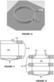
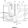
- the heating head 500 comprises a series of disk flanges 523, 524 and 525 extending outwardly from the conduit portion 528 of the heating head and having preferably circumference surfaces 503, 504 and 505 operating as the electrical contacts for connection with the of the tightening rings 501 or 502 (see Figs. 11 and 12 ).
- the disk flanges 523, 524 and 525 may either be made of electrically conductive material, aka covering the entire thickness of the part or alternatively comprises a layer of electrically conductive material about the surface or inside the disk flanges 523, 524 and 525. It applies similarly to the conduit portion 528 of the heating head 500, wherein the conduit surface 529, aka interior surface of the conduit portion 528, should feature electrically conductive material on its surface for optimal heating of the material 510.
- the tightening rings are single piece tightening rings 501 or multi-piece, for example, two pieces, tightening rings 502, wherein the extremity of the tightening rings 501, 502 are either attached to each other (for example tightening rings 501 ) or attached to each other (for example tightening rings 502 ) to form a closed ring or ring assembly contacting and inwardly pressing tightly the complete circumference surfaces 503, 504, 505 of the disk flanges 523, 524 for optimal electrical contact therebetween.
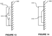
- the tightening rings 501 or 502 are cooled down via a flow of cooling fluid.
- the tightening rings 501, 502 comprise either one or more recesses, for example, recess 515, limited by the combination of the structure 514 of the tightening ring 501, 502 or alternatively one or more conduits, for examples the two conduits 513, totally enclosed in the structure 512 of the tightening rings 501, 502 and isolated from the heating head 500.
- the cooling fluid may be for instance air, water, oil, or another heat exchange fluid that may be circulated in the examples conduits 513 or recess 515.
- the tightening rings 501, 502 may further provide a combined function of support when connected to a support structure, wherein the tightening rings 501, 502 provides aid in alignment and/or displacement of the heating head 500.
- the design of the heating head 500 allows the use of multiple tightening rings 501, 502 operating as multiple electrical connectors, and thus additional control of the circulation of the current in the heating head 500.
- sensors 516 and 517 may be connected to the heating head 500 to measure the temperature of the heating head 500 and to adjust, in real-time or almost in real-time, the power transmitted to the tightening rings 501, 502 to monitor and control the operation of the heating head 500.
- the heating head 500 may have a longer conduit featuring a greater number of temperature-controlled sections, wherein the temperature in each of the sections may be controlled by controlling the power transmitted to the tightening rings mounted to the disk flanges that are boundary to the temperature-controlled section, for example, disk flanges 524 an 525 for the top section of the conduit on Fig. 15 .
- sensors for example, sensors 516 and 517, may be located at different locations along the conduit 508 to monitor and control finely each of the temperature-controlled sections of the heating head 500.
- the heating head 500 may be free of material between the disk flanges 523, 524 and 525. According to alternative realizations, the heating head 500 may feature electrically insulating material between two neighbor disk flanges, for example filling the space therebetween or vertical radial membranes. When needed, the additional material may provide extra robustness to the heating head 500. Other reasons, including other structural reasons and fabrication reasons, are also contemplated therethrough.
- a needle valve 506 of a suitable material is used, centered relative to the conduit 508, mounted from a support (not depicted) at its top, wherein the needle valve 506 provides aid for flow control by, for example, changing gas pressure and/or changing output temperature.
- the needle valve 506 is moveable up and down deeper in the melting or melted material 510.
- the needle valve 506 is cooled down at or about its support, above the level of the material 510.
- electrodes 507 are partially immersed in the conduit 508, and more precisely in a portion wherein the material 510 is at least partially molten in a molten material 509.
- This realization has the advantages of solving the issues of the presence of oxides on the surface when the material consists in aluminum granules, while being able to operate at a working temperature of between about seven hundred (700) degrees Celsius and about one thousand (1000) degrees Celsius. Furthermore, contrary to large-scale aluminum production in which electrodes can weigh a ton or more, the present electrodes are a lot smaller, in the hundreds of grams range, and can be made of a suitable premium material.
- the controlled use of electrodes by disconnecting them from the heating head may allow, depending on the melted material, controlled use of the melted material as a medium for the passage of electricity. In these cases, it is possible to obtain a partial electrolysis of the material.
- additional electrode(s) for example an electrically powered needle valve 506
- additional electrode(s) for example an electrically powered needle valve 506
- the electrolysis of the material will increase flow of material while generating gas in it close to the exit to the heating head.
- the generated gas will remain enclosed in the material when deposited and thereby permanently modify the characteristics of the material among which an increase of the thermal insulation characteristics of the material.
- material having increased thermal insulation is for housing.
- the head assembly 110 or heating head 420 or 500 may be designed to have a gradient of temperature since thicker conductive layer providing a greater cross area for the electricity to pass through while a thinner layer providing a smaller cross area, thus more resistance, for the passage of the electricity, and thus generating more heat.
- the fabrication of the heating head according to a preferred method of fabrication involves deposition layer by layer of different powders which are pressed and/or sintered between each layer to generate in each layer areas of conductive material, for example, made of a mix of metal and ceramic, and potentially also of electrically insulating material, for example, made of ceramic only.
- the preferred fabrication method may also involve machining surfaces of the pieces, for example, space between disk flanges and the conduit surface 529.
Landscapes
- Chemical & Material Sciences (AREA)
- Engineering & Computer Science (AREA)
- Materials Engineering (AREA)
- Manufacturing & Machinery (AREA)
- Physics & Mathematics (AREA)
- Mechanical Engineering (AREA)
- Optics & Photonics (AREA)
Claims (11)
- Ein Kopfaufbau (110) für einen FDM-Drucker (100), der Folgendes umfasst:
einen Heizkopf (120) (420) (500) mit:einem Oberteil (181);einem Unterteil (183);einer sich zwischen dem Oberteil (181) und dem Unterteil (183) verlaufenden Leitung (184) (508) mit einer Leitungsoberfläche (197) (529) zum Durchleiten eines Materialflusses (90) (510);mit der Eigenschaft, dass sieeine leitfähige Schicht aufweist, die einen Widerstand entlang der Leitungsoberfläche (197) (529) zur Erzeugung von Wärme bewirkt, wenn elektrischer Strom innerhalb der leitfähigen Schicht fließt. - Kopfaufbau (110) nach Anspruch 1, wobei die leitfähige Schicht aus einer Kombination von Keramik- und Metallpulver hergestellt ist.
- Kopfaufbau (110) nach einem der Ansprüche 1 und 2, wobei die leitfähige Schicht von der Oberseite (181) zur Unterseite (183) des Heizkopfes (120) (420) (500) verläuft.
- Kopfaufbau (110) nach einem der Ansprüche 1 bis 3, wobei die leitfähige Schicht eine erste Dicke an einem ersten Umfang in einem ersten Abstand von der Oberseite (181) und eine zweite Dicke an einem zweiten Umfang in einem zweiten größeren Abstand von der Oberseite (181) des Heizkopfes (120) (420) (500) als der erste Umfang aufweist.
- Kopfaufbau (110) nach Anspruch 4, wobei die Temperatur am zweiten Umfang höher ist als die am ersten Umfang.
- Kopfaufbau (110) nach einem der Ansprüche 1 bis 5, wobei der Heizkopf (120) (420) (500) eine von der Leitungsoberfläche (529) (197) entfernte elektrisch isolierende Schicht aufweist.
- Kopfaufbau (110) nach einem der Ansprüche 1 bis 6, wobei die leitfähige Schicht eine Mindestdicke zwischen 1 und 10 mm aufweist.
- Kopfaufbau (110) nach einem der Ansprüche 1 bis 7, wobei die leitfähige Schicht in ihrer Gesamtheit über die Leitungsoberfläche (529) (197) verläuft.
- Kopfaufbau (110) nach einem der Ansprüche 1 bis 8, wobei die leitfähige Schicht über mindestens einen Teil der Oberseite (181) und/oder der Unterseite (183) des Heizkopfs verläuft.
- Kopfaufbau (110) nach einem der Ansprüche 1 bis 9, der ferner Folgendes umfasst:einen oberen elektrischen Verbinder (191), der die leitfähige Schicht an die Oberseite (181) oder in die Nähe der Oberseite des Heizkopfs (120) (420) (500) anschließt;einen unteren elektrischen Verbinder (192), der die leitfähige Schicht an der Unterseite (183) oder in der Nähe der Unterseite des Heizkopfs (120) (420) (500) anschließt; undeine Spannungskomponente, die mindestens eines der folgenden Elemente aktiviert:der obere elektrische Verbinder (191) in Richtung der leitfähigen Schicht;und der untere elektrische Verbinder (192) in Richtung der leitfähigen Schicht.
- Kopfaufbau (110) nach Anspruch 10, wobei entweder der obere elektrische Verbinder (191) oder der untere elektrische Verbinder (192) eine wulstartige Oberfläche aufweist.
Applications Claiming Priority (2)
| Application Number | Priority Date | Filing Date | Title |
|---|---|---|---|
| US201962947370P | 2019-12-12 | 2019-12-12 | |
| PCT/CA2020/051555 WO2021113955A1 (en) | 2019-12-12 | 2020-11-13 | Very high temperature hot end for fused deposition modelling printer |
Publications (3)
| Publication Number | Publication Date |
|---|---|
| EP3880439A1 EP3880439A1 (de) | 2021-09-22 |
| EP3880439A4 EP3880439A4 (de) | 2021-12-29 |
| EP3880439B1 true EP3880439B1 (de) | 2024-07-03 |
Family
ID=76329180
Family Applications (1)
| Application Number | Title | Priority Date | Filing Date |
|---|---|---|---|
| EP20897612.6A Active EP3880439B1 (de) | 2019-12-12 | 2020-11-13 | Heissende mit sehr hoher temperatur für einen schmelzschichtungsdrucker |
Country Status (4)
| Country | Link |
|---|---|
| US (1) | US11633916B2 (de) |
| EP (1) | EP3880439B1 (de) |
| CA (1) | CA3120527C (de) |
| WO (1) | WO2021113955A1 (de) |
Families Citing this family (3)
| Publication number | Priority date | Publication date | Assignee | Title |
|---|---|---|---|---|
| CN115502412B (zh) * | 2022-09-28 | 2024-06-21 | 中国航空制造技术研究院 | 一种TiAl单晶材料的电子束选区熔化增材制造方法 |
| CN117261217A (zh) * | 2023-10-31 | 2023-12-22 | 昆山英福斯三维科技有限公司 | 3d打印防堵吐头 |
| CN119610884B (zh) * | 2025-01-14 | 2025-10-17 | 西北工业大学 | 一种气溶胶喷墨打印装置及其沉积效率调控方法 |
Citations (2)
| Publication number | Priority date | Publication date | Assignee | Title |
|---|---|---|---|---|
| CN105773979A (zh) * | 2016-05-05 | 2016-07-20 | 赖柱彭 | 3d打印笔 |
| CN208896509U (zh) * | 2018-08-28 | 2019-05-24 | 北京化工大学 | 一种同轴3d打印设备 |
Family Cites Families (24)
| Publication number | Priority date | Publication date | Assignee | Title |
|---|---|---|---|---|
| US5121329A (en) | 1989-10-30 | 1992-06-09 | Stratasys, Inc. | Apparatus and method for creating three-dimensional objects |
| CN101605641B (zh) | 2007-02-12 | 2012-01-18 | 斯特拉塔西斯公司 | 用于基于挤压的沉积系统的粘性泵 |
| US9022769B2 (en) | 2010-07-22 | 2015-05-05 | Stratasys, Inc. | Multiple-zone liquefier assembly for extrusion-based additive manufacturing systems |
| CN102529366B (zh) | 2012-01-13 | 2014-12-17 | 华中科技大学 | 一种基于静电喷印制备阵列化图案的装置和方法 |
| US20150307385A1 (en) | 2014-04-25 | 2015-10-29 | Massachusetts Institute Of Technology | Methods and apparatus for additive manufacturing of glass |
| CN104099675B (zh) | 2014-07-25 | 2016-01-20 | 北京化工大学 | 一种可用于3d打印的静电纺丝装置 |
| WO2016110403A1 (en) | 2015-01-06 | 2016-07-14 | Philips Lighting Holding B.V. | Method and printer head for 3d printing of glass |
| CN105984142B (zh) | 2015-01-27 | 2019-01-11 | 常州市东科电子科技有限公司 | 一种双排孔填充3d打印头 |
| CN105196550B (zh) | 2015-10-30 | 2018-01-23 | 兰红波 | 一种单喷头多材料多尺度3d打印装置及其工作方法 |
| CN105538715A (zh) | 2016-01-05 | 2016-05-04 | 杭州捷诺飞生物科技有限公司 | 高温打印喷头及应用其的3d打印设备 |
| US9919510B2 (en) | 2016-04-12 | 2018-03-20 | Massachusetts Institute Of Technology | Methods and apparatus for additive manufacturing with molten glass |
| IL264629B2 (en) | 2016-08-05 | 2024-11-01 | Jabil Inc | Device, system and method for forming print nozzles for melt layering of materials |
| CN206106378U (zh) | 2016-10-10 | 2017-04-19 | 湖南信息职业技术学院 | 一种3d打印自动退丝装置 |
| CN106313501B (zh) | 2016-10-20 | 2018-09-04 | 西北工业大学 | 一种直流电脉冲控制的熔滴沉积3d打印装置及打印方法 |
| WO2018156458A1 (en) * | 2017-02-24 | 2018-08-30 | Essentium Materials, Llc | Atmospheric plasma conduction pathway for the application of electromagentic energy to 3d printed parts |
| US20190022961A1 (en) * | 2017-07-18 | 2019-01-24 | GM Global Technology Operations LLC | Method for fused filament fabrication of a thermoplastic part including induction heating |
| CN107225753B (zh) | 2017-07-26 | 2019-06-25 | 江西珠穆朗玛智能科技有限公司 | 一种可自清洁的3d打印机耗材喷头 |
| CN108356270B (zh) | 2018-03-26 | 2020-06-09 | 厦门大学 | 一种基于接触电阻加热的金属3d打印方法 |
| EP3560687A1 (de) * | 2018-04-23 | 2019-10-30 | Bond high performance 3D technology B.V. | System zur generativen fertigung |
| US20220072765A1 (en) * | 2018-12-19 | 2022-03-10 | Jabil Inc. | Apparatus, system and method for plug clearing in an additive manufacturing print head |
| CN110127992A (zh) | 2019-06-27 | 2019-08-16 | 厦门大学 | 一种熔融沉积成型的玻璃3d打印装置及其打印方法 |
| CN110421850B (zh) | 2019-08-29 | 2021-07-13 | 金肯职业技术学院 | 一种防物料残留的3d打印机喷头及其使用方法 |
| CN211222088U (zh) * | 2019-11-19 | 2020-08-11 | 浙江师徒智能科技有限公司 | 一种小型化3d打印机加热体 |
| US20210178670A1 (en) * | 2019-12-12 | 2021-06-17 | Research Foundation for State University of New York | Additive manufacturing systems and methods of forming components using same |
-
2020
- 2020-11-13 EP EP20897612.6A patent/EP3880439B1/de active Active
- 2020-11-13 WO PCT/CA2020/051555 patent/WO2021113955A1/en not_active Ceased
- 2020-11-13 US US17/296,919 patent/US11633916B2/en active Active
- 2020-11-13 CA CA3120527A patent/CA3120527C/en active Active
Patent Citations (2)
| Publication number | Priority date | Publication date | Assignee | Title |
|---|---|---|---|---|
| CN105773979A (zh) * | 2016-05-05 | 2016-07-20 | 赖柱彭 | 3d打印笔 |
| CN208896509U (zh) * | 2018-08-28 | 2019-05-24 | 北京化工大学 | 一种同轴3d打印设备 |
Also Published As
| Publication number | Publication date |
|---|---|
| CA3120527A1 (en) | 2021-06-12 |
| US20220314544A1 (en) | 2022-10-06 |
| US11633916B2 (en) | 2023-04-25 |
| EP3880439A1 (de) | 2021-09-22 |
| WO2021113955A1 (en) | 2021-06-17 |
| CA3120527C (en) | 2023-03-21 |
| EP3880439A4 (de) | 2021-12-29 |
Similar Documents
| Publication | Publication Date | Title |
|---|---|---|
| EP3880439B1 (de) | Heissende mit sehr hoher temperatur für einen schmelzschichtungsdrucker | |
| US11110540B2 (en) | Extruder for metal material and 3D printer using the same | |
| CN106715027B (zh) | 用于等离子弧焊炬的成本有效的筒 | |
| US11845223B2 (en) | Apparatus, system and method of operating an additive manufacturing nozzle | |
| CN105216334A (zh) | 一种感应加热器、3d打印机挤出机 | |
| EP3455047B1 (de) | Materialschmelzvorrichtung | |
| EP3810405B1 (de) | Vorrichtung zur materialabgabe und vorrichtung zur additiven fertigung, die diese umfasst | |
| US20130306686A1 (en) | Hot Runner Nozzle | |
| US20250041935A1 (en) | Metal additive manufacturing apparatus and methods | |
| CN106392076A (zh) | 3d打印系统及其喷头装置 | |
| KR20220116215A (ko) | 금속-기반 와이어-플라즈마 아크 적층 제조 적용예들을 위한 체적 플라즈마 가스 유동 측정 및 제어 시스템 | |
| EP3898194A1 (de) | Vorrichtung, system und verfahren zum betrieb einer düse zur generativen fertigung | |
| EP3663073A1 (de) | 3d-druck-kopfsystem mit kombinierten verarbeitungsabschnitten und einem integral angeformten verarbeitungskanal für die generative fertigung | |
| EP3259090B1 (de) | Schweissbrenner und vorrichtung mit diesem brenner | |
| US11260590B1 (en) | Flow control of molten material and gas extraction via electrolysis | |
| KR20170077301A (ko) | 삼차원 프린터용 노즐 어셈블리 | |
| RU182033U1 (ru) | Печатающая головка устройства для объемной печати расплавленным металлом | |
| JP2013202490A (ja) | フィルタ、およびろ過装置 | |
| CA2988198C (en) | Induction plasma torch with higher plasma energy density | |
| CN108161003A (zh) | 一种3d打印用激光头装置 | |
| TR2023004652A1 (tr) | Soğutma Tabanlı Eklemeli İmalat Makinesi |
Legal Events
| Date | Code | Title | Description |
|---|---|---|---|
| STAA | Information on the status of an ep patent application or granted ep patent |
Free format text: STATUS: UNKNOWN |
|
| STAA | Information on the status of an ep patent application or granted ep patent |
Free format text: STATUS: THE INTERNATIONAL PUBLICATION HAS BEEN MADE |
|
| PUAI | Public reference made under article 153(3) epc to a published international application that has entered the european phase |
Free format text: ORIGINAL CODE: 0009012 |
|
| STAA | Information on the status of an ep patent application or granted ep patent |
Free format text: STATUS: REQUEST FOR EXAMINATION WAS MADE |
|
| 17P | Request for examination filed |
Effective date: 20210613 |
|
| AK | Designated contracting states |
Kind code of ref document: A1 Designated state(s): AL AT BE BG CH CY CZ DE DK EE ES FI FR GB GR HR HU IE IS IT LI LT LU LV MC MK MT NL NO PL PT RO RS SE SI SK SM TR |
|
| A4 | Supplementary search report drawn up and despatched |
Effective date: 20211129 |
|
| RIC1 | Information provided on ipc code assigned before grant |
Ipc: B33Y 30/00 20150101ALI20211123BHEP Ipc: B29C 64/209 20170101AFI20211123BHEP |
|
| DAV | Request for validation of the european patent (deleted) | ||
| DAX | Request for extension of the european patent (deleted) | ||
| STAA | Information on the status of an ep patent application or granted ep patent |
Free format text: STATUS: EXAMINATION IS IN PROGRESS |
|
| 17Q | First examination report despatched |
Effective date: 20230628 |
|
| REG | Reference to a national code |
Ref country code: DE Ref legal event code: R079 Free format text: PREVIOUS MAIN CLASS: B29C0064209000 Ipc: B29C0064118000 Ref document number: 602020033555 Country of ref document: DE |
|
| GRAP | Despatch of communication of intention to grant a patent |
Free format text: ORIGINAL CODE: EPIDOSNIGR1 |
|
| STAA | Information on the status of an ep patent application or granted ep patent |
Free format text: STATUS: GRANT OF PATENT IS INTENDED |
|
| RIC1 | Information provided on ipc code assigned before grant |
Ipc: B33Y 30/00 20150101ALI20240213BHEP Ipc: B29C 64/209 20170101ALI20240213BHEP Ipc: B33Y 10/00 20150101ALI20240213BHEP Ipc: B29C 64/295 20170101ALI20240213BHEP Ipc: B29C 64/118 20170101AFI20240213BHEP |
|
| INTG | Intention to grant announced |
Effective date: 20240320 |
|
| RAP3 | Party data changed (applicant data changed or rights of an application transferred) |
Owner name: KILNCORE INC. |
|
| RIN1 | Information on inventor provided before grant (corrected) |
Inventor name: MISSOUT, ANTOINE |
|
| GRAS | Grant fee paid |
Free format text: ORIGINAL CODE: EPIDOSNIGR3 |
|
| GRAA | (expected) grant |
Free format text: ORIGINAL CODE: 0009210 |
|
| STAA | Information on the status of an ep patent application or granted ep patent |
Free format text: STATUS: THE PATENT HAS BEEN GRANTED |
|
| AK | Designated contracting states |
Kind code of ref document: B1 Designated state(s): AL AT BE BG CH CY CZ DE DK EE ES FI FR GB GR HR HU IE IS IT LI LT LU LV MC MK MT NL NO PL PT RO RS SE SI SK SM TR |
|
| REG | Reference to a national code |
Ref country code: CH Ref legal event code: EP |
|
| REG | Reference to a national code |
Ref country code: DE Ref legal event code: R096 Ref document number: 602020033555 Country of ref document: DE |
|
| REG | Reference to a national code |
Ref country code: LT Ref legal event code: MG9D |
|
| REG | Reference to a national code |
Ref country code: NL Ref legal event code: MP Effective date: 20240703 |
|
| PG25 | Lapsed in a contracting state [announced via postgrant information from national office to epo] |
Ref country code: PT Free format text: LAPSE BECAUSE OF FAILURE TO SUBMIT A TRANSLATION OF THE DESCRIPTION OR TO PAY THE FEE WITHIN THE PRESCRIBED TIME-LIMIT Effective date: 20241104 |
|
| REG | Reference to a national code |
Ref country code: AT Ref legal event code: MK05 Ref document number: 1699401 Country of ref document: AT Kind code of ref document: T Effective date: 20240703 |
|
| PG25 | Lapsed in a contracting state [announced via postgrant information from national office to epo] |
Ref country code: NL Free format text: LAPSE BECAUSE OF FAILURE TO SUBMIT A TRANSLATION OF THE DESCRIPTION OR TO PAY THE FEE WITHIN THE PRESCRIBED TIME-LIMIT Effective date: 20240703 |
|
| PG25 | Lapsed in a contracting state [announced via postgrant information from national office to epo] |
Ref country code: PT Free format text: LAPSE BECAUSE OF FAILURE TO SUBMIT A TRANSLATION OF THE DESCRIPTION OR TO PAY THE FEE WITHIN THE PRESCRIBED TIME-LIMIT Effective date: 20241104 Ref country code: NL Free format text: LAPSE BECAUSE OF FAILURE TO SUBMIT A TRANSLATION OF THE DESCRIPTION OR TO PAY THE FEE WITHIN THE PRESCRIBED TIME-LIMIT Effective date: 20240703 |
|
| PG25 | Lapsed in a contracting state [announced via postgrant information from national office to epo] |
Ref country code: NO Free format text: LAPSE BECAUSE OF FAILURE TO SUBMIT A TRANSLATION OF THE DESCRIPTION OR TO PAY THE FEE WITHIN THE PRESCRIBED TIME-LIMIT Effective date: 20241003 |
|
| PG25 | Lapsed in a contracting state [announced via postgrant information from national office to epo] |
Ref country code: FI Free format text: LAPSE BECAUSE OF FAILURE TO SUBMIT A TRANSLATION OF THE DESCRIPTION OR TO PAY THE FEE WITHIN THE PRESCRIBED TIME-LIMIT Effective date: 20240703 Ref country code: GR Free format text: LAPSE BECAUSE OF FAILURE TO SUBMIT A TRANSLATION OF THE DESCRIPTION OR TO PAY THE FEE WITHIN THE PRESCRIBED TIME-LIMIT Effective date: 20241004 Ref country code: PL Free format text: LAPSE BECAUSE OF FAILURE TO SUBMIT A TRANSLATION OF THE DESCRIPTION OR TO PAY THE FEE WITHIN THE PRESCRIBED TIME-LIMIT Effective date: 20240703 |
|
| PG25 | Lapsed in a contracting state [announced via postgrant information from national office to epo] |
Ref country code: BG Free format text: LAPSE BECAUSE OF FAILURE TO SUBMIT A TRANSLATION OF THE DESCRIPTION OR TO PAY THE FEE WITHIN THE PRESCRIBED TIME-LIMIT Effective date: 20240703 |
|
| PG25 | Lapsed in a contracting state [announced via postgrant information from national office to epo] |
Ref country code: LV Free format text: LAPSE BECAUSE OF FAILURE TO SUBMIT A TRANSLATION OF THE DESCRIPTION OR TO PAY THE FEE WITHIN THE PRESCRIBED TIME-LIMIT Effective date: 20240703 |
|
| PG25 | Lapsed in a contracting state [announced via postgrant information from national office to epo] |
Ref country code: IS Free format text: LAPSE BECAUSE OF FAILURE TO SUBMIT A TRANSLATION OF THE DESCRIPTION OR TO PAY THE FEE WITHIN THE PRESCRIBED TIME-LIMIT Effective date: 20241103 Ref country code: AT Free format text: LAPSE BECAUSE OF FAILURE TO SUBMIT A TRANSLATION OF THE DESCRIPTION OR TO PAY THE FEE WITHIN THE PRESCRIBED TIME-LIMIT Effective date: 20240703 |
|
| PG25 | Lapsed in a contracting state [announced via postgrant information from national office to epo] |
Ref country code: HR Free format text: LAPSE BECAUSE OF FAILURE TO SUBMIT A TRANSLATION OF THE DESCRIPTION OR TO PAY THE FEE WITHIN THE PRESCRIBED TIME-LIMIT Effective date: 20240703 Ref country code: CZ Free format text: LAPSE BECAUSE OF FAILURE TO SUBMIT A TRANSLATION OF THE DESCRIPTION OR TO PAY THE FEE WITHIN THE PRESCRIBED TIME-LIMIT Effective date: 20240703 |
|
| PG25 | Lapsed in a contracting state [announced via postgrant information from national office to epo] |
Ref country code: ES Free format text: LAPSE BECAUSE OF FAILURE TO SUBMIT A TRANSLATION OF THE DESCRIPTION OR TO PAY THE FEE WITHIN THE PRESCRIBED TIME-LIMIT Effective date: 20240703 Ref country code: RS Free format text: LAPSE BECAUSE OF FAILURE TO SUBMIT A TRANSLATION OF THE DESCRIPTION OR TO PAY THE FEE WITHIN THE PRESCRIBED TIME-LIMIT Effective date: 20241003 |
|
| PG25 | Lapsed in a contracting state [announced via postgrant information from national office to epo] |
Ref country code: RS Free format text: LAPSE BECAUSE OF FAILURE TO SUBMIT A TRANSLATION OF THE DESCRIPTION OR TO PAY THE FEE WITHIN THE PRESCRIBED TIME-LIMIT Effective date: 20241003 Ref country code: PL Free format text: LAPSE BECAUSE OF FAILURE TO SUBMIT A TRANSLATION OF THE DESCRIPTION OR TO PAY THE FEE WITHIN THE PRESCRIBED TIME-LIMIT Effective date: 20240703 Ref country code: NO Free format text: LAPSE BECAUSE OF FAILURE TO SUBMIT A TRANSLATION OF THE DESCRIPTION OR TO PAY THE FEE WITHIN THE PRESCRIBED TIME-LIMIT Effective date: 20241003 Ref country code: LV Free format text: LAPSE BECAUSE OF FAILURE TO SUBMIT A TRANSLATION OF THE DESCRIPTION OR TO PAY THE FEE WITHIN THE PRESCRIBED TIME-LIMIT Effective date: 20240703 Ref country code: IS Free format text: LAPSE BECAUSE OF FAILURE TO SUBMIT A TRANSLATION OF THE DESCRIPTION OR TO PAY THE FEE WITHIN THE PRESCRIBED TIME-LIMIT Effective date: 20241103 Ref country code: HR Free format text: LAPSE BECAUSE OF FAILURE TO SUBMIT A TRANSLATION OF THE DESCRIPTION OR TO PAY THE FEE WITHIN THE PRESCRIBED TIME-LIMIT Effective date: 20240703 Ref country code: GR Free format text: LAPSE BECAUSE OF FAILURE TO SUBMIT A TRANSLATION OF THE DESCRIPTION OR TO PAY THE FEE WITHIN THE PRESCRIBED TIME-LIMIT Effective date: 20241004 Ref country code: FI Free format text: LAPSE BECAUSE OF FAILURE TO SUBMIT A TRANSLATION OF THE DESCRIPTION OR TO PAY THE FEE WITHIN THE PRESCRIBED TIME-LIMIT Effective date: 20240703 Ref country code: ES Free format text: LAPSE BECAUSE OF FAILURE TO SUBMIT A TRANSLATION OF THE DESCRIPTION OR TO PAY THE FEE WITHIN THE PRESCRIBED TIME-LIMIT Effective date: 20240703 Ref country code: CZ Free format text: LAPSE BECAUSE OF FAILURE TO SUBMIT A TRANSLATION OF THE DESCRIPTION OR TO PAY THE FEE WITHIN THE PRESCRIBED TIME-LIMIT Effective date: 20240703 Ref country code: BG Free format text: LAPSE BECAUSE OF FAILURE TO SUBMIT A TRANSLATION OF THE DESCRIPTION OR TO PAY THE FEE WITHIN THE PRESCRIBED TIME-LIMIT Effective date: 20240703 Ref country code: AT Free format text: LAPSE BECAUSE OF FAILURE TO SUBMIT A TRANSLATION OF THE DESCRIPTION OR TO PAY THE FEE WITHIN THE PRESCRIBED TIME-LIMIT Effective date: 20240703 |
|
| REG | Reference to a national code |
Ref country code: DE Ref legal event code: R097 Ref document number: 602020033555 Country of ref document: DE |
|
| PG25 | Lapsed in a contracting state [announced via postgrant information from national office to epo] |
Ref country code: DK Free format text: LAPSE BECAUSE OF FAILURE TO SUBMIT A TRANSLATION OF THE DESCRIPTION OR TO PAY THE FEE WITHIN THE PRESCRIBED TIME-LIMIT Effective date: 20240703 Ref country code: RO Free format text: LAPSE BECAUSE OF FAILURE TO SUBMIT A TRANSLATION OF THE DESCRIPTION OR TO PAY THE FEE WITHIN THE PRESCRIBED TIME-LIMIT Effective date: 20240703 Ref country code: SM Free format text: LAPSE BECAUSE OF FAILURE TO SUBMIT A TRANSLATION OF THE DESCRIPTION OR TO PAY THE FEE WITHIN THE PRESCRIBED TIME-LIMIT Effective date: 20240703 |
|
| PG25 | Lapsed in a contracting state [announced via postgrant information from national office to epo] |
Ref country code: EE Free format text: LAPSE BECAUSE OF FAILURE TO SUBMIT A TRANSLATION OF THE DESCRIPTION OR TO PAY THE FEE WITHIN THE PRESCRIBED TIME-LIMIT Effective date: 20240703 |
|
| PG25 | Lapsed in a contracting state [announced via postgrant information from national office to epo] |
Ref country code: SK Free format text: LAPSE BECAUSE OF FAILURE TO SUBMIT A TRANSLATION OF THE DESCRIPTION OR TO PAY THE FEE WITHIN THE PRESCRIBED TIME-LIMIT Effective date: 20240703 |
|
| PLBE | No opposition filed within time limit |
Free format text: ORIGINAL CODE: 0009261 |
|
| STAA | Information on the status of an ep patent application or granted ep patent |
Free format text: STATUS: NO OPPOSITION FILED WITHIN TIME LIMIT |
|
| 26N | No opposition filed |
Effective date: 20250404 |
|
| REG | Reference to a national code |
Ref country code: CH Ref legal event code: PL |
|
| PG25 | Lapsed in a contracting state [announced via postgrant information from national office to epo] |
Ref country code: MC Free format text: LAPSE BECAUSE OF FAILURE TO SUBMIT A TRANSLATION OF THE DESCRIPTION OR TO PAY THE FEE WITHIN THE PRESCRIBED TIME-LIMIT Effective date: 20240703 |
|
| PG25 | Lapsed in a contracting state [announced via postgrant information from national office to epo] |
Ref country code: LU Free format text: LAPSE BECAUSE OF NON-PAYMENT OF DUE FEES Effective date: 20241113 |
|
| REG | Reference to a national code |
Ref country code: CH Ref legal event code: PL |
|
| PG25 | Lapsed in a contracting state [announced via postgrant information from national office to epo] |
Ref country code: CH Free format text: LAPSE BECAUSE OF NON-PAYMENT OF DUE FEES Effective date: 20241130 |
|
| REG | Reference to a national code |
Ref country code: BE Ref legal event code: MM Effective date: 20241130 |
|
| PG25 | Lapsed in a contracting state [announced via postgrant information from national office to epo] |
Ref country code: SE Free format text: LAPSE BECAUSE OF FAILURE TO SUBMIT A TRANSLATION OF THE DESCRIPTION OR TO PAY THE FEE WITHIN THE PRESCRIBED TIME-LIMIT Effective date: 20240703 |
|
| PG25 | Lapsed in a contracting state [announced via postgrant information from national office to epo] |
Ref country code: BE Free format text: LAPSE BECAUSE OF NON-PAYMENT OF DUE FEES Effective date: 20241130 |
|
| PG25 | Lapsed in a contracting state [announced via postgrant information from national office to epo] |
Ref country code: IE Free format text: LAPSE BECAUSE OF NON-PAYMENT OF DUE FEES Effective date: 20241113 |
|
| PGFP | Annual fee paid to national office [announced via postgrant information from national office to epo] |
Ref country code: DE Payment date: 20251020 Year of fee payment: 6 |
|
| PGFP | Annual fee paid to national office [announced via postgrant information from national office to epo] |
Ref country code: GB Payment date: 20251121 Year of fee payment: 6 |
|
| PGFP | Annual fee paid to national office [announced via postgrant information from national office to epo] |
Ref country code: IT Payment date: 20251118 Year of fee payment: 6 |
|
| PGFP | Annual fee paid to national office [announced via postgrant information from national office to epo] |
Ref country code: FR Payment date: 20251124 Year of fee payment: 6 |
|
| PG25 | Lapsed in a contracting state [announced via postgrant information from national office to epo] |
Ref country code: HU Free format text: LAPSE BECAUSE OF FAILURE TO SUBMIT A TRANSLATION OF THE DESCRIPTION OR TO PAY THE FEE WITHIN THE PRESCRIBED TIME-LIMIT; INVALID AB INITIO Effective date: 20201113 |
|
| PG25 | Lapsed in a contracting state [announced via postgrant information from national office to epo] |
Ref country code: CY Free format text: LAPSE BECAUSE OF FAILURE TO SUBMIT A TRANSLATION OF THE DESCRIPTION OR TO PAY THE FEE WITHIN THE PRESCRIBED TIME-LIMIT; INVALID AB INITIO Effective date: 20201113 |