EP3879849A1 - Speaker diaphragm - Google Patents
Speaker diaphragm Download PDFInfo
- Publication number
- EP3879849A1 EP3879849A1 EP19883180.2A EP19883180A EP3879849A1 EP 3879849 A1 EP3879849 A1 EP 3879849A1 EP 19883180 A EP19883180 A EP 19883180A EP 3879849 A1 EP3879849 A1 EP 3879849A1
- Authority
- EP
- European Patent Office
- Prior art keywords
- speaker diaphragm
- polymer
- polyolefin
- thermoplastic resin
- speaker
- Prior art date
- Legal status (The legal status is an assumption and is not a legal conclusion. Google has not performed a legal analysis and makes no representation as to the accuracy of the status listed.)
- Pending
Links
Images


Classifications
-
- H—ELECTRICITY
- H04—ELECTRIC COMMUNICATION TECHNIQUE
- H04R—LOUDSPEAKERS, MICROPHONES, GRAMOPHONE PICK-UPS OR LIKE ACOUSTIC ELECTROMECHANICAL TRANSDUCERS; ELECTRIC HEARING AIDS; PUBLIC ADDRESS SYSTEMS
- H04R7/00—Diaphragms for electromechanical transducers; Cones
- H04R7/02—Diaphragms for electromechanical transducers; Cones characterised by the construction
- H04R7/12—Non-planar diaphragms or cones
- H04R7/122—Non-planar diaphragms or cones comprising a plurality of sections or layers
-
- B—PERFORMING OPERATIONS; TRANSPORTING
- B32—LAYERED PRODUCTS
- B32B—LAYERED PRODUCTS, i.e. PRODUCTS BUILT-UP OF STRATA OF FLAT OR NON-FLAT, e.g. CELLULAR OR HONEYCOMB, FORM
- B32B27/00—Layered products comprising a layer of synthetic resin
- B32B27/06—Layered products comprising a layer of synthetic resin as the main or only constituent of a layer, which is next to another layer of the same or of a different material
-
- B—PERFORMING OPERATIONS; TRANSPORTING
- B32—LAYERED PRODUCTS
- B32B—LAYERED PRODUCTS, i.e. PRODUCTS BUILT-UP OF STRATA OF FLAT OR NON-FLAT, e.g. CELLULAR OR HONEYCOMB, FORM
- B32B27/00—Layered products comprising a layer of synthetic resin
- B32B27/32—Layered products comprising a layer of synthetic resin comprising polyolefins
-
- H—ELECTRICITY
- H04—ELECTRIC COMMUNICATION TECHNIQUE
- H04R—LOUDSPEAKERS, MICROPHONES, GRAMOPHONE PICK-UPS OR LIKE ACOUSTIC ELECTROMECHANICAL TRANSDUCERS; ELECTRIC HEARING AIDS; PUBLIC ADDRESS SYSTEMS
- H04R31/00—Apparatus or processes specially adapted for the manufacture of transducers or diaphragms therefor
- H04R31/003—Apparatus or processes specially adapted for the manufacture of transducers or diaphragms therefor for diaphragms or their outer suspension
-
- B—PERFORMING OPERATIONS; TRANSPORTING
- B32—LAYERED PRODUCTS
- B32B—LAYERED PRODUCTS, i.e. PRODUCTS BUILT-UP OF STRATA OF FLAT OR NON-FLAT, e.g. CELLULAR OR HONEYCOMB, FORM
- B32B2250/00—Layers arrangement
- B32B2250/03—3 layers
-
- B—PERFORMING OPERATIONS; TRANSPORTING
- B32—LAYERED PRODUCTS
- B32B—LAYERED PRODUCTS, i.e. PRODUCTS BUILT-UP OF STRATA OF FLAT OR NON-FLAT, e.g. CELLULAR OR HONEYCOMB, FORM
- B32B2250/00—Layers arrangement
- B32B2250/40—Symmetrical or sandwich layers, e.g. ABA, ABCBA, ABCCBA
-
- B—PERFORMING OPERATIONS; TRANSPORTING
- B32—LAYERED PRODUCTS
- B32B—LAYERED PRODUCTS, i.e. PRODUCTS BUILT-UP OF STRATA OF FLAT OR NON-FLAT, e.g. CELLULAR OR HONEYCOMB, FORM
- B32B2270/00—Resin or rubber layer containing a blend of at least two different polymers
-
- H—ELECTRICITY
- H04—ELECTRIC COMMUNICATION TECHNIQUE
- H04R—LOUDSPEAKERS, MICROPHONES, GRAMOPHONE PICK-UPS OR LIKE ACOUSTIC ELECTROMECHANICAL TRANSDUCERS; ELECTRIC HEARING AIDS; PUBLIC ADDRESS SYSTEMS
- H04R2307/00—Details of diaphragms or cones for electromechanical transducers, their suspension or their manufacture covered by H04R7/00 or H04R31/003, not provided for in any of its subgroups
- H04R2307/025—Diaphragms comprising polymeric materials
-
- H—ELECTRICITY
- H04—ELECTRIC COMMUNICATION TECHNIQUE
- H04R—LOUDSPEAKERS, MICROPHONES, GRAMOPHONE PICK-UPS OR LIKE ACOUSTIC ELECTROMECHANICAL TRANSDUCERS; ELECTRIC HEARING AIDS; PUBLIC ADDRESS SYSTEMS
- H04R2307/00—Details of diaphragms or cones for electromechanical transducers, their suspension or their manufacture covered by H04R7/00 or H04R31/003, not provided for in any of its subgroups
- H04R2307/029—Diaphragms comprising fibres
Definitions
- the present invention relates to a speaker diaphragm.
- Patent Document 1 discloses a speaker diaphragm formed by injection molding (see Japanese Unexamined Patent Application, Publication No. S62-253300 ).
- Patent Document 1 Japanese Unexamined Patent Application, Publication No. S62-253300
- the speaker diaphragm disclosed in Patent Document 1 is in a cone shape, and can be obtained by injecting a molten resin into a cavity of a die from a central part of the cavity (a part corresponding to a bottom of the speaker diaphragm) and conducting injection molding.
- This speaker diaphragm is formed by curing the resin which has been injected into and flowed within the cavity.
- this speaker diaphragm it is difficult to control anisotropy of an elastic modulus due to a molecular orientation which results from the flow of the resin.
- the prevent invention was made in view of the aforementioned problem, and an object of the present invention is to provide a speaker diaphragm in which an elastic modulus can be readily controlled.
- a speaker diaphragm according to one aspect of the present invention made for solving the aforementioned problem contains a first polymer and a second polymer, wherein
- the speaker diaphragm according to one aspect of the present invention contains a first polymer and a second polymer, wherein the first polymer and the second polymer undergo phase separation, the first polymer is a polyolefin and the second polymer is a thermoplastic resin being immiscible with the polyolefin, and one of either the polyolefin or the thermoplastic resin constitutes a sea phase, and another one of either the polyolefin or the thermoplastic resin constitutes island phases being interspersed in the sea phase.
- the speaker diaphragm may be in a cone shape.
- a difference between a melting point of the polyolefin and a melting point of the thermoplastic resin is preferably 20 °C or less.
- the polyolefin is preferably polymethylpentene.
- thermoplastic resin is preferably a liquid crystal polymer.
- the island phases are preferably present in surface layers in a radial form.
- the speaker diaphragm preferably further contains polyparaphenylenebenzobisoxazole fibers.
- melting point means a peak melting point temperature measured by differential scanning calorimetry (DSC) in accordance with JIS-K7121:2012 (testing methods for transition temperatures of plastics).
- anisotropy of an elastic modulus due to a molecular orientation of one of either the first polymer or the second polymer can be controlled by the other one of either the first polymer or the second polymer.
- anisotropy of an elastic modulus as referred to herein means a property in which the elastic modulus differs in a direction of intersection, and in the case of the speaker diaphragm of the one aspect of the present invention being in the cone shape, "anisotropy of the elastic modulus” means a property in which the elastic modulus in a radial direction differs from that in a circumferential direction.
- the speaker diaphragm in FIGs. 1 and 2 contains a first polymer and a second polymer which undergo phase separation from each other.
- the first polymer is a polyolefin
- the second polymer is a thermoplastic resin being immiscible with the polyolefin.
- the thermoplastic resin constitutes a sea phase 1a
- the polyolefin constitutes island phases 1b being interspersed in the sea phase 1a.
- blending the first polymer and the second polymer results in phase separation into the two phase types, being the sea phase 1a and the island phases 1b.
- the speaker diaphragm can be configured to be in a shape in accordance with a speaker to be used, and in FIGs. 1 and 2 , the speaker diaphragm is in the cone shape. Furthermore, a size of the speaker diaphragm can be set in accordance with the speaker to be used.
- the speaker diaphragm may be for use in a small speaker to be provided in, for example, headphones, earphones, portable electronic devices, or the like.
- the "cone shape” as referred to herein means a shape having a cylindrical circumferential wall that expands in diameter from a back side toward a front side with respect to a central axial direction, and this shape may include a bottom which closes an end opening on the back side of the circumferential wall.
- the "front side” as referred to herein means a side of a sound-emitting direction
- the "back side” as referred to herein means a side being opposite to the front side.
- the speaker diaphragm may have a shape in which only a part expands in diameter from the back side toward the front side with respect to the central axial direction of the circumferential wall, but the entire circumferential wall expanding in diameter from the back side toward the front side with respect to the central axial direction is preferred.
- the speaker diaphragm has a base layer 1 containing the sea phase 1a and the island phases 1b being interspersed in the sea phase 1a.
- the speaker diaphragm is a single-layer body of the base layer 1.
- the base layer 1 can be formed by injection molding, described later.
- the base layer 1 may have: a pair of skin layers disposed respectively on the front side and the back side, which come into contact with the cavity of the die; and a core layer being disposed between the skin layers and having a molecular orientation which differs from that of the skin layers.
- the speaker diaphragm has substantially uniform thickness.
- the lower limit of an average thickness T of the speaker diaphragm is preferably 50 ⁇ m, and more preferably 300 ⁇ m.
- the upper limit of the average thickness T of the speaker diaphragm is preferably 800 ⁇ m, and more preferably 650 ⁇ m.
- the average thickness T is less than the lower limit, rigidity of the speaker diaphragm may be insufficient, and/or it may be difficult to form the speaker diaphragm by the injection molding.
- the average thickness T exceeds the upper limit, the speaker diaphragm may become unduly heavy.
- the "average thickness" as referred to herein means an average value of thicknesses at 10 arbitrary points.
- thermoplastic resin examples include a liquid crystal polymer, polystyrene, a fluororesin, a polycarbonate, a polysulfone, a polyether sulfone, a polyacetal, polyethylene terephthalate, polybutylene terephthalate, a polyamide, a polyimide, acrylonitrile-butadiene-styrene, and the like.
- the thermoplastic resin is preferably the liquid crystal polymer, which has superior flowability in the cavity of the die in the case of forming the speaker diaphragm by injection molding, with the molecular orientation being easily controllable.
- the molecular orientation of the thermoplastic resin, the anisotropy of the elastic modulus due to the molecular orientation, and the like are adjusted by the polyolefin.
- polystyrene resin examples include polyethylene, polypropylene, polybutene, polymethylpentene, polyisobutylene, an ethylene-propylene copolymer, an ethylene-vinyl acetate copolymer, and the like.
- the polyolefin is preferably polymethylpentene, which has superior flowability in the cavity of the die, and is low in density with a bulky side chain, thereby enabling facilitation of weight reduction of the speaker diaphragm.
- thermoplastic resin is the liquid crystal polymer and the polyolefin is polymethylpentene is particularly preferable.
- the liquid crystal polymer easily constitutes the sea phase 1a, and polymethylpentene easily constitutes the island phases 1b.
- the liquid crystal polymer since the liquid crystal polymer has better flowability than polymethylpentene in the cavity of the die, it is considered that a proportion of the liquid crystal polymer in the skin layers tends to be greater than a proportion of the liquid crystal polymer in the core layer.
- the speaker diaphragm when a proportion of polymethylpentene in the skin layers is comparatively reduced, it is considered that a change in material thickness resulting from shrinkage in molding of polymethylpentene is easily suppressed.
- the speaker diaphragm has the combination in which the thermoplastic resin is the liquid crystal polymer and the polyolefin is polymethylpentene, the island phases 1b are more easily scattered in the surface layers in a radial form, as described later. As a result, it is thought that with respect to the speaker diaphragm, weight reduction is promoted, and the anisotropy of the elastic modulus resulting from the liquid crystal polymer can be easily adjusted by the island phases 1b.
- the lower limit of a number average molecular weight (Mn) of the liquid crystal polymer is preferably 3,000, and more preferably 10,000.
- the upper limit of the Mn is preferably 100,000, and more preferably 80,000.
- Mn number average molecular weight
- the lower limit of the Mn of polymethylpentene is preferably 5,000, and more preferably 15,000.
- the upper limit of the Mn is preferably 1,000,000, and more preferably 500,000.
- the Mn is less than the lower limit, the rigidity of the speaker diaphragm may be insufficient.
- the Mn exceeds the upper limit the moldability by the injection molding may be insufficient.
- the Mn of polymethylpentene is preferably greater than the Mn of the liquid crystal polymer.
- the lower limit of a content of the polyolefin with respect to 100 parts by mass of the thermoplastic resin in the base layer 1 is preferably 30 parts by mass, more preferably 40 parts by mass, and still more preferably 50 parts by mass.
- the upper limit of the content is preferably 80 parts by mass, more preferably 70 parts by mass, and still more preferably 60 parts by mass.
- the lower limit of a content of the polyolefin in the base layer 1 is preferably 20% by mass, and more preferably 30% by mass.
- the upper limit of the content of the polyolefin in the base layer 1 is preferably 50% by mass, and more preferably 40% by mass.
- the content is less than the lower limit, it may be difficult to adjust the anisotropy of the elastic modulus.
- the rigidity of the speaker diaphragm may be insufficient, and/or it may be difficult to uniformly disperse the island phases 1b in the sea phase 1a.
- the lower limit of a content of the thermoplastic resin in the base layer 1 is preferably 50% by mass, and more preferably 60% by mass.
- the upper limit of the content of the thermoplastic resin in the base layer 1 is preferably 80% by mass, and more preferably 70% by mass.
- the content is less than the lower limit, the rigidity of the speaker diaphragm may be insufficient, and/or it may be difficult to uniformly disperse the island phases 1b in the sea phase 1a.
- the content exceeds the upper limit, it may not be possible to sufficiently include the polyolefin in the base layer 1; thus, it may be difficult to adjust the anisotropy of the elastic modulus.
- a melting point of the polyolefin and a melting point of the thermoplastic resin are preferably substantially equal.
- the upper limit of a difference between the melting point of the polyolefin and the melting point of the thermoplastic resin is preferably 20 °C, and more preferably 15 °C. When the difference between the melting points exceeds the upper limit, it may be difficult to form the speaker diaphragm by injection molding. It is to be noted that with regard to the difference between the melting points, a smaller difference is preferable, and the lower limit of the difference can be 0 °C.
- the speaker diaphragm With regard to the speaker diaphragm, a quality such as the anisotropy of the elastic modulus can be adjusted by including the polyolefin and the thermoplastic resin together.
- the speaker diaphragm may have a structure not including fiber components such as reinforcing fibers.
- the speaker diaphragm may have a structure including reinforcing fibers.
- polyparaphenylenebenzobisoxazole fibers are preferred as the reinforcing fibers.
- a content of the polyparaphenylenebenzobisoxazole fibers with respect to 100 parts by mass of the thermoplastic resin can be, for example, 5 parts by mass or more and 40 parts by mass or less.
- the speaker diaphragm may contain other component(s), such as a coloring agent, an ultraviolet ray-absorbing agent, and/or the like, within a range not leading to impairment of the effects of the present invention.
- the island phases 1b are preferably present in the surface layers in the radial form.
- the island phases may radially extend, or may be radially scattered as shown in FIGs. 1 and 2 . More specifically, each of a plurality of the island phases 1b dispersed in the circumferential direction may extend in an elongated form in a radial direction of the speaker diaphragm, or the plurality of the island phases 1b, being in a scattered form, may be arranged in the radial form as a whole.
- the form of the island phases 1b in the surface layers can be regulated by controlling the flowability of the polyolefin and the thermoplastic resin in the cavity of the die.
- the anisotropy of the elastic modulus tends to increase.
- the anisotropy of the elastic modulus due to the molecular orientation of the thermoplastic resin tends to decrease in the speaker diaphragm.
- the "surface layers” as referred to herein mean the skin layers.
- the "surface layers” as referred to herein mean, for example, regions lying 20 ⁇ m or less in depth from each of a face on the front side and a face on the back side of the speaker diaphragm.
- the method of producing the speaker diaphragm includes a step (injection-molding step) of injection molding a resin composition (diaphragm-forming material) containing a first polymer and a second polymer which are immiscible with respect to each other.
- the first polymer is a polyolefin
- the second polymer is a thermoplastic resin.
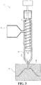
- the injection-molding step can be conducted using an injection molding apparatus 11 shown in FIG. 3 .
- the injection molding apparatus 3 has: a cylinder 12 which has a nozzle 12a at a tip thereof; a hopper 13 which is connected to the cylinder 12, and into which the diaphragm-forming material is charged; a screw 14 which is mounted inside the cylinder 12; and a mold 15, having formed therein a cavity 15a which communicates with an opening of the nozzle 12a.
- the cavity 15a has a shape being an inversion of that of the speaker diaphragm. A part of the cavity 15a which corresponds to the bottom of the speaker diaphragm communicates with the opening of the nozzle 12a.
- the cavity 15a is radially filled, from the part corresponding to the bottom of the speaker diaphragm, with a melt of the diaphragm-forming material. Furthermore, in the injection-molding step, after the filling with the melt, the cavity 15a is cooled, whereby the melt is hardened. A molded product obtained by hardening the melt is configured as the speaker diaphragm.
- a cylinder temperature in the injection-molding step is preferably set depending on the melting point of the polyolefin.
- the lower limit of the cylinder temperature is preferably 300 °C, and more preferably 310 °C.
- the upper limit of the cylinder temperature is preferably 350 °C, and more preferably 320 °C.
- the anisotropy of the elastic modulus due to the molecular orientation of one of either the first polymer or the second polymer can be controlled by the other one of either the first polymer or the second polymer.
- the anisotropy of the elastic modulus due to the molecular orientation of the thermoplastic resin constituting the sea phase 1a can be controlled by the island phases 1b, which are interspersed in the sea phase 1a. Furthermore, in the speaker diaphragm, the anisotropy of the elastic modulus is easily confirmed visually due to the sea phase 1a and the island phases 1b, and improving designability is enabled due to interspersing the island phases 1b in the sea phase 1a.
- the method of producing the speaker diaphragm enables easily producing the speaker diaphragm of the one embodiment of the present invention.
- the polyolefin may constitute a sea phase, and a thermoplastic resin being immiscible with the polyolefin may constitute island phases being interspersed in the sea phase.
- the anisotropy of the elastic modulus due to the molecular orientation of the polyolefin can be adjusted by the thermoplastic resin.
- a content of the polyolefin in the base layer can be set similarly to the content of the thermoplastic resin in the base layer 1 of the one embodiment of the present invention.
- a content of the thermoplastic resin with respect to 100 parts by mass of the polyolefin can be set similarly to the content of the polyolefin with respect to 100 parts by mass of the thermoplastic resin in the one embodiment of the present invention.
- a content of the polyparaphenylenebenzobisoxazole fibers with respect to 100 parts by mass of the polyolefin can be set similarly to the content of the polyparaphenylenebenzobisoxazole fibers with respect to 100 parts by mass of the thermoplastic resin in the one embodiment of the present invention.
- Cone-shaped speaker diaphragm No. 1 being constituted from a single-layer body of the base layer, and having an average thickness of 450 ⁇ m, was produced by injection molding a diaphragm-forming material constituted from: a liquid crystal polymer as the thermoplastic resin; and polymethylpentene as the polyolefin being immiscible with the thermoplastic resin.
- a liquid crystal polymer as the thermoplastic resin
- polymethylpentene as the polyolefin being immiscible with the thermoplastic resin.
- the liquid crystal polymer "A8100,” manufactured by Ueno Fine Chemicals Industry, Ltd. and having a melting point of 220 °C, was used, and as polymethylpentene, "RT31,” produced by Mitsui Chemical, Inc. and having a melting point of 232 °C, was used.
- RT31 polymethylpentene
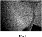
- FIG. 4 A photograph of this speaker diaphragm taken from the back side is shown in FIG. 4 .
- the speaker diaphragm had a sea phase constituted from the liquid crystal polymer, and island phases constituted from polymethylpentene and being interspersed in the sea phase.
- the speaker diaphragm had a pair of skin layers and a core layer being disposed between the skin layers, and as illustrated in Fig. 4 , the island phases were radially scattered in the surface layers (skin layers).
- Speaker diaphragm No. 2 having an average thickness of 500 um, was produced similarly to No. 1, except that the content of polymethylpentene with respect to 100 parts by mass of the liquid crystal polymer was set to 100 parts by mass.
- the speaker diaphragm had a sea phase constituted from the liquid crystal polymer, and island phases constituted from polymethylpentene and being interspersed in the sea phase.
- the speaker diaphragm had a pair of skin layers and a core layer being disposed between the skin layers, and the island phases were radially scattered in the surface layers (skin layers).
- Speaker diaphragm No. 3 having an average thickness of 500 ⁇ m, was produced similarly to No. 1, except that a diaphragm-forming material being constituted from solely the liquid crystal polymer ("A8100," produced by Ueno Fine Chemicals Industry, Ltd.) having a melting point of 220 °C was used.
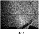
- a photograph of this speaker diaphragm taken from the back side is shown in FIG. 5 .
- the liquid crystal polymer was radially oriented in the surface layers.
- Speaker diaphragm No. 4 having an average thickness of 390 ⁇ m, was produced similarly to No. 1, except that a diaphragm-forming material being constituted from solely polymethylpentene ("RT31,” produced by Mitsui Chemical, Inc.) having a melting point of 232 °C was used.
- RT31 solely polymethylpentene
- the density (g/cm 3 ) of each of the speaker diaphragms No. 1 to No. 4 was measured.
- the density was determined by: cutting out a test piece being 5 mm x 40 mm; then determining a volume of the test piece by calculating an average thickness based on average thickness values at three arbitrary points; and dividing a weight of the test piece by the calculated volume.
- the measurement results are shown in Table 1.
- a storage elastic modulus (GPa) in each of a radial direction and a circumferential direction was measured at 250 Hz and 1,000 Hz for each of the speaker diaphragms No. 1 to No. 4.
- a rectangular sample having a width of 5 mm, a length of 40 mm, and a thickness of 0.5 mm was cut out from each of the speaker diaphragms No. 1 to No. 4, and a dynamic viscoelasticity measurement apparatus ("DMA+150") manufactured by Metravib was used to measure the storage elastic modulus at 23 ⁇ 2 °C in a pulling mode. The measurement results are shown in Table 1.
- Table 1 Content of polymethylpentene with respect to 100 parts by mass of liquid crystal polymer (parts by mass) Density (g/cm 3 ) Storage elastic modulus (GPa) 250 Hz 1,000 Hz radial direction circumferential direction radial direction / circumferential direction radial direction circumferential direction radial direction / circumferential direction No. 1 56 1.07 4.54 2.33 1.95 5.97 2.92 2.04 No. 2 100 1.15 6.51 2.60 2.50 8.66 3.28 2.64 No. 3 0 1.27 8.48 3.28 2.59 11.60 4.33 2.68 No. 4 - 0.91 1.81 1.86 0.97 2.23 2.31 0.97
- Each of the speaker diaphragms No. 1 and No. 2 has the island phases interspersed in the sea phase, with the island phases being radially scattered in the surface layers; therefore, adjusting the anisotropy of the elastic modulus to be less is enabled by reducing the ratio of the storage elastic modulus in the circumferential direction to the storage elastic modulus in the radial direction, as shown in Table 1, compared with the speaker diaphragm No. 3, which is constituted solely from the liquid crystal polymer. Moreover, comparison between the speaker diaphragms No. 1 and No. 2 indicates that adjusting the anisotropy of the elastic modulus to be less has been enabled in the speaker diaphragm No. 1, in which the content of polymethylpentene is lower.
- the speaker diaphragms No. 1 and No. 2 enable achieving a reduction in weight compared to the speaker diaphragm No. 3, which is constituted from the liquid crystal polymer.
- the anisotropy is easily controlled; thus, the speaker diaphragm can be suitably used as a cone-shaped diaphragm.
Landscapes
- Engineering & Computer Science (AREA)
- Physics & Mathematics (AREA)
- Acoustics & Sound (AREA)
- Signal Processing (AREA)
- Multimedia (AREA)
- Manufacturing & Machinery (AREA)
- Diaphragms For Electromechanical Transducers (AREA)
- Injection Moulding Of Plastics Or The Like (AREA)
- Compositions Of Macromolecular Compounds (AREA)
Abstract
Description
- The present invention relates to a speaker diaphragm.
- Recently, in light of attempts to, for example, improve moisture resistance and reduce weight, speaker diaphragms in which a synthetic resin is employed in place of wood have been used. Patent Document 1 discloses a speaker diaphragm formed by injection molding (see
Japanese Unexamined Patent Application, Publication No. S62-253300 - Patent Document 1:
Japanese Unexamined Patent Application, Publication No. S62-253300 - The speaker diaphragm disclosed in Patent Document 1 is in a cone shape, and can be obtained by injecting a molten resin into a cavity of a die from a central part of the cavity (a part corresponding to a bottom of the speaker diaphragm) and conducting injection molding.
- This speaker diaphragm is formed by curing the resin which has been injected into and flowed within the cavity. Thus, in the case of this speaker diaphragm, it is difficult to control anisotropy of an elastic modulus due to a molecular orientation which results from the flow of the resin.
- The prevent invention was made in view of the aforementioned problem, and an object of the present invention is to provide a speaker diaphragm in which an elastic modulus can be readily controlled.
- A speaker diaphragm according to one aspect of the present invention made for solving the aforementioned problem contains a first polymer and a second polymer, wherein
- the first polymer and the second polymer undergo phase separation,
- the first polymer is a polyolefin and the second polymer is a thermoplastic resin being immiscible with the polyolefin, and
- one of either the polyolefin or the thermoplastic resin constitutes a sea phase, and another one of either the polyolefin or the thermoplastic resin constitutes island phases being interspersed in the sea phase.
-
-
FIG. 1 is a schematic front view of a speaker diaphragm according to one embodiment of the present invention. -
FIG. 2 is a cross-sectional view of the speaker diaphragm, taken along A-A inFIG. 1 . -
FIG. 3 is a schematic view illustrating a production apparatus for the speaker diaphragm inFIG. 1 . -
FIG. 4 is a photographic image taken from a back side of speaker diaphragm No. 1. -
FIG. 5 is a photographic image taken from a back side of speaker diaphragm No. 3. - The speaker diaphragm according to one aspect of the present invention contains a first polymer and a second polymer, wherein the first polymer and the second polymer undergo phase separation, the first polymer is a polyolefin and the second polymer is a thermoplastic resin being immiscible with the polyolefin, and one of either the polyolefin or the thermoplastic resin constitutes a sea phase, and another one of either the polyolefin or the thermoplastic resin constitutes island phases being interspersed in the sea phase.
- The speaker diaphragm may be in a cone shape.
- A difference between a melting point of the polyolefin and a melting point of the thermoplastic resin is preferably 20 °C or less.
- The polyolefin is preferably polymethylpentene.
- The thermoplastic resin is preferably a liquid crystal polymer.
- In the speaker diaphragm, the island phases are preferably present in surface layers in a radial form.
- The speaker diaphragm preferably further contains polyparaphenylenebenzobisoxazole fibers.
- It is to be noted that the "melting point" as referred to herein means a peak melting point temperature measured by differential scanning calorimetry (DSC) in accordance with JIS-K7121:2012 (testing methods for transition temperatures of plastics).
- Due to the first polymer and the second polymer undergoing phase separation from each other, anisotropy of an elastic modulus due to a molecular orientation of one of either the first polymer or the second polymer can be controlled by the other one of either the first polymer or the second polymer. It is to be noted that "anisotropy of an elastic modulus" as referred to herein means a property in which the elastic modulus differs in a direction of intersection, and in the case of the speaker diaphragm of the one aspect of the present invention being in the cone shape, "anisotropy of the elastic modulus" means a property in which the elastic modulus in a radial direction differs from that in a circumferential direction.
- Hereinafter, embodiments of the present invention will be described in detail with reference to a drawing or drawings as appropriate.
- The speaker diaphragm in
FIGs. 1 and2 contains a first polymer and a second polymer which undergo phase separation from each other. - In the speaker diaphragm of the one embodiment of the present invention, the first polymer is a polyolefin, and the second polymer is a thermoplastic resin being immiscible with the polyolefin. In the speaker diaphragm, the thermoplastic resin constitutes a
sea phase 1a, and the polyolefin constitutesisland phases 1b being interspersed in thesea phase 1a. In other words, with regard to the speaker diaphragm, blending the first polymer and the second polymer results in phase separation into the two phase types, being thesea phase 1a and theisland phases 1b. - The speaker diaphragm can be configured to be in a shape in accordance with a speaker to be used, and in
FIGs. 1 and2 , the speaker diaphragm is in the cone shape. Furthermore, a size of the speaker diaphragm can be set in accordance with the speaker to be used. The speaker diaphragm may be for use in a small speaker to be provided in, for example, headphones, earphones, portable electronic devices, or the like. It is to be noted that the "cone shape" as referred to herein means a shape having a cylindrical circumferential wall that expands in diameter from a back side toward a front side with respect to a central axial direction, and this shape may include a bottom which closes an end opening on the back side of the circumferential wall. Furthermore, the "front side" as referred to herein means a side of a sound-emitting direction, and the "back side" as referred to herein means a side being opposite to the front side. The speaker diaphragm may have a shape in which only a part expands in diameter from the back side toward the front side with respect to the central axial direction of the circumferential wall, but the entire circumferential wall expanding in diameter from the back side toward the front side with respect to the central axial direction is preferred. - The speaker diaphragm has a base layer 1 containing the
sea phase 1a and theisland phases 1b being interspersed in thesea phase 1a. The speaker diaphragm, is a single-layer body of the base layer 1. The base layer 1 can be formed by injection molding, described later. The base layer 1 may have: a pair of skin layers disposed respectively on the front side and the back side, which come into contact with the cavity of the die; and a core layer being disposed between the skin layers and having a molecular orientation which differs from that of the skin layers. - The speaker diaphragm has substantially uniform thickness. The lower limit of an average thickness T of the speaker diaphragm is preferably 50 µm, and more preferably 300 µm. On the other hand, the upper limit of the average thickness T of the speaker diaphragm is preferably 800 µm, and more preferably 650 µm. When the average thickness T is less than the lower limit, rigidity of the speaker diaphragm may be insufficient, and/or it may be difficult to form the speaker diaphragm by the injection molding. Conversely, when the average thickness T exceeds the upper limit, the speaker diaphragm may become unduly heavy. It is to be noted that the "average thickness" as referred to herein means an average value of thicknesses at 10 arbitrary points.
- Examples of the thermoplastic resin include a liquid crystal polymer, polystyrene, a fluororesin, a polycarbonate, a polysulfone, a polyether sulfone, a polyacetal, polyethylene terephthalate, polybutylene terephthalate, a polyamide, a polyimide, acrylonitrile-butadiene-styrene, and the like. Of these, the thermoplastic resin is preferably the liquid crystal polymer, which has superior flowability in the cavity of the die in the case of forming the speaker diaphragm by injection molding, with the molecular orientation being easily controllable.
- In the speaker diaphragm, the molecular orientation of the thermoplastic resin, the anisotropy of the elastic modulus due to the molecular orientation, and the like are adjusted by the polyolefin.
- Examples of the polyolefin include polyethylene, polypropylene, polybutene, polymethylpentene, polyisobutylene, an ethylene-propylene copolymer, an ethylene-vinyl acetate copolymer, and the like. Of these, the polyolefin is preferably polymethylpentene, which has superior flowability in the cavity of the die, and is low in density with a bulky side chain, thereby enabling facilitation of weight reduction of the speaker diaphragm.
- With respect to the speaker diaphragm, a combination in which the thermoplastic resin is the liquid crystal polymer and the polyolefin is polymethylpentene is particularly preferable. According to this combination, the liquid crystal polymer easily constitutes the
sea phase 1a, and polymethylpentene easily constitutes theisland phases 1b. Furthermore, according to this combination, since the liquid crystal polymer has better flowability than polymethylpentene in the cavity of the die, it is considered that a proportion of the liquid crystal polymer in the skin layers tends to be greater than a proportion of the liquid crystal polymer in the core layer. Thus, with respect to the speaker diaphragm, when a proportion of polymethylpentene in the skin layers is comparatively reduced, it is considered that a change in material thickness resulting from shrinkage in molding of polymethylpentene is easily suppressed. Moreover, when the speaker diaphragm has the combination in which the thermoplastic resin is the liquid crystal polymer and the polyolefin is polymethylpentene, the island phases 1b are more easily scattered in the surface layers in a radial form, as described later. As a result, it is thought that with respect to the speaker diaphragm, weight reduction is promoted, and the anisotropy of the elastic modulus resulting from the liquid crystal polymer can be easily adjusted by the island phases 1b. In addition, since polymethylpentene has superior transparency, contrast between thesea phase 1a and theisland phases 1b is enhanced, and therefore thesea phase 1a and the island phases 1b are easily confirmed visually. In other words, due to thus causing phase separation into the two phase types, characteristics arising from the sea-island phase structure can be utilized, unlike a single phase being in a miscible state in a molecular order. - The lower limit of a number average molecular weight (Mn) of the liquid crystal polymer is preferably 3,000, and more preferably 10,000. On the other hand, the upper limit of the Mn is preferably 100,000, and more preferably 80,000. When the Mn is less than the lower limit, the rigidity of the speaker diaphragm may be insufficient. Conversely, when the Mn exceeds the upper limit, moldability by the injection molding may be insufficient. It is to be noted that "number average molecular weight (Mn)" as referred to herein means a polystyrene-equivalent value determined by gel permeation chromatography.
- The lower limit of the Mn of polymethylpentene is preferably 5,000, and more preferably 15,000. On the other hand, the upper limit of the Mn is preferably 1,000,000, and more preferably 500,000. When the Mn is less than the lower limit, the rigidity of the speaker diaphragm may be insufficient. Conversely, when the Mn exceeds the upper limit, the moldability by the injection molding may be insufficient. It is to be noted that with regard to the speaker diaphragm, in light of ease in increasing the proportion of the liquid crystal polymer in the surface layers, the Mn of polymethylpentene is preferably greater than the Mn of the liquid crystal polymer.
- The lower limit of a content of the polyolefin with respect to 100 parts by mass of the thermoplastic resin in the base layer 1 (i.e., the speaker diaphragm) is preferably 30 parts by mass, more preferably 40 parts by mass, and still more preferably 50 parts by mass. On the other hand, the upper limit of the content is preferably 80 parts by mass, more preferably 70 parts by mass, and still more preferably 60 parts by mass. When the content is less than the lower limit, it may be difficult to adjust the anisotropy of the elastic modulus resulting from the thermoplastic resin. Conversely, when the content exceeds the upper limit, the rigidity of the speaker diaphragm may be insufficient, and/or it may be difficult to uniformly disperse the island phases 1b in the
sea phase 1a. - The lower limit of a content of the polyolefin in the base layer 1 is preferably 20% by mass, and more preferably 30% by mass. On the other hand, the upper limit of the content of the polyolefin in the base layer 1 is preferably 50% by mass, and more preferably 40% by mass. When the content is less than the lower limit, it may be difficult to adjust the anisotropy of the elastic modulus. Conversely, when the content exceeds the upper limit, the rigidity of the speaker diaphragm may be insufficient, and/or it may be difficult to uniformly disperse the island phases 1b in the
sea phase 1a. - The lower limit of a content of the thermoplastic resin in the base layer 1 is preferably 50% by mass, and more preferably 60% by mass. On the other hand, the upper limit of the content of the thermoplastic resin in the base layer 1 is preferably 80% by mass, and more preferably 70% by mass. When the content is less than the lower limit, the rigidity of the speaker diaphragm may be insufficient, and/or it may be difficult to uniformly disperse the island phases 1b in the
sea phase 1a. Conversely, when the content exceeds the upper limit, it may not be possible to sufficiently include the polyolefin in the base layer 1; thus, it may be difficult to adjust the anisotropy of the elastic modulus. - A melting point of the polyolefin and a melting point of the thermoplastic resin are preferably substantially equal. The upper limit of a difference between the melting point of the polyolefin and the melting point of the thermoplastic resin is preferably 20 °C, and more preferably 15 °C. When the difference between the melting points exceeds the upper limit, it may be difficult to form the speaker diaphragm by injection molding. It is to be noted that with regard to the difference between the melting points, a smaller difference is preferable, and the lower limit of the difference can be 0 °C.
- With regard to the speaker diaphragm, a quality such as the anisotropy of the elastic modulus can be adjusted by including the polyolefin and the thermoplastic resin together. Thus, the speaker diaphragm may have a structure not including fiber components such as reinforcing fibers. On the other hand, in light of preventing cracking and the like, the speaker diaphragm may have a structure including reinforcing fibers. In the case of containing the reinforcing fibers in the speaker diaphragm, polyparaphenylenebenzobisoxazole fibers are preferred as the reinforcing fibers. When the speaker diaphragm contains the polyparaphenylenebenzobisoxazole fibers, weight reduction can be achieved, and unintended cracking can be easily and certainly prevented.
- In the case of the speaker diaphragm containing the polyparaphenylenebenzobisoxazole fibers, a content of the polyparaphenylenebenzobisoxazole fibers with respect to 100 parts by mass of the thermoplastic resin can be, for example, 5 parts by mass or more and 40 parts by mass or less.
- It is to be noted that the speaker diaphragm may contain other component(s), such as a coloring agent, an ultraviolet ray-absorbing agent, and/or the like, within a range not leading to impairment of the effects of the present invention.
- In the speaker diaphragm, the island phases 1b are preferably present in the surface layers in the radial form. In the case in which the island phases 1b are present in the surface layers in the radial form, the island phases may radially extend, or may be radially scattered as shown in
FIGs. 1 and2 . More specifically, each of a plurality of the island phases 1b dispersed in the circumferential direction may extend in an elongated form in a radial direction of the speaker diaphragm, or the plurality of the island phases 1b, being in a scattered form, may be arranged in the radial form as a whole. In the speaker diaphragm, the form of the island phases 1b in the surface layers can be regulated by controlling the flowability of the polyolefin and the thermoplastic resin in the cavity of the die. In the speaker diaphragm, in the case in which the island phases 1b radially extend in the surface layers, a difference between the elastic modulus in the radial direction and the elastic modulus in the circumferential direction tends to be comparatively large; thus, the anisotropy of the elastic modulus tends to increase. On the other hand, in the case in which the island phases 1b are radially scattered in the surface layers, the anisotropy of the elastic modulus due to the molecular orientation of the thermoplastic resin tends to decrease in the speaker diaphragm. It is to be noted that in the case in which the speaker diaphragm has the skin layers and the core layer, the "surface layers" as referred to herein mean the skin layers. Furthermore, in the case in which the speaker diaphragm does not have either of the skin layers or the core layer, the "surface layers" as referred to herein mean, for example, regions lying 20 µm or less in depth from each of a face on the front side and a face on the back side of the speaker diaphragm. - Next, a method of producing the speaker diaphragm will be described. The method of producing the speaker diaphragm includes a step (injection-molding step) of injection molding a resin composition (diaphragm-forming material) containing a first polymer and a second polymer which are immiscible with respect to each other. The first polymer is a polyolefin, and the second polymer is a thermoplastic resin.
- For example, the injection-molding step can be conducted using an
injection molding apparatus 11 shown inFIG. 3 . The injection molding apparatus 3 has: acylinder 12 which has anozzle 12a at a tip thereof; ahopper 13 which is connected to thecylinder 12, and into which the diaphragm-forming material is charged; ascrew 14 which is mounted inside thecylinder 12; and amold 15, having formed therein acavity 15a which communicates with an opening of thenozzle 12a. Thecavity 15a has a shape being an inversion of that of the speaker diaphragm. A part of thecavity 15a which corresponds to the bottom of the speaker diaphragm communicates with the opening of thenozzle 12a. In the injection-molding step, thecavity 15a is radially filled, from the part corresponding to the bottom of the speaker diaphragm, with a melt of the diaphragm-forming material. Furthermore, in the injection-molding step, after the filling with the melt, thecavity 15a is cooled, whereby the melt is hardened. A molded product obtained by hardening the melt is configured as the speaker diaphragm. - A cylinder temperature in the injection-molding step is preferably set depending on the melting point of the polyolefin. For example, in the case in which the polyolefin is polymethylpentene, the lower limit of the cylinder temperature is preferably 300 °C, and more preferably 310 °C. On the other hand, the upper limit of the cylinder temperature is preferably 350 °C, and more preferably 320 °C. When the cylinder temperature is less than the lower limit, the flowability of the polyolefin may be insufficient, and thus it may be difficult to appropriately control, by the polyolefin, the anisotropy of the elastic modulus of the speaker diaphragm to be obtained. Conversely, when the cylinder temperature exceeds the upper limit, efficiency of producing the speaker diaphragm may be inferior.
- Due to the first polymer and the second polymer phase-separating from each other in the speaker diaphragm, the anisotropy of the elastic modulus due to the molecular orientation of one of either the first polymer or the second polymer can be controlled by the other one of either the first polymer or the second polymer.
- In the speaker diaphragm, the anisotropy of the elastic modulus due to the molecular orientation of the thermoplastic resin constituting the
sea phase 1a can be controlled by the island phases 1b, which are interspersed in thesea phase 1a. Furthermore, in the speaker diaphragm, the anisotropy of the elastic modulus is easily confirmed visually due to thesea phase 1a and the island phases 1b, and improving designability is enabled due to interspersing the island phases 1b in thesea phase 1a. - The method of producing the speaker diaphragm enables easily producing the speaker diaphragm of the one embodiment of the present invention.
- The embodiments described above do not restrict the constituent features of the present invention. Therefore, constituent elements of each part of the above-described embodiments may be omitted, replaced, or added based on the description in the present specification and common technical knowledge, and such omission, replacement, and addition should be construed as falling within the scope of the present invention.
- In the speaker diaphragm, the polyolefin may constitute a sea phase, and a thermoplastic resin being immiscible with the polyolefin may constitute island phases being interspersed in the sea phase. In this case, in the speaker diaphragm, the anisotropy of the elastic modulus due to the molecular orientation of the polyolefin can be adjusted by the thermoplastic resin. Further, in this case, a content of the polyolefin in the base layer can be set similarly to the content of the thermoplastic resin in the base layer 1 of the one embodiment of the present invention. Moreover, a content of the thermoplastic resin with respect to 100 parts by mass of the polyolefin can be set similarly to the content of the polyolefin with respect to 100 parts by mass of the thermoplastic resin in the one embodiment of the present invention. Furthermore, in the case of the speaker diaphragm further containing the polyparaphenylenebenzobisoxazole fibers, a content of the polyparaphenylenebenzobisoxazole fibers with respect to 100 parts by mass of the polyolefin can be set similarly to the content of the polyparaphenylenebenzobisoxazole fibers with respect to 100 parts by mass of the thermoplastic resin in the one embodiment of the present invention.
- Hereinafter, the present disclosure will be further described in detail by way of Examples, but the present invention is not to be interpreted as limited based on the following Examples.
- Cone-shaped speaker diaphragm No. 1, being constituted from a single-layer body of the base layer, and having an average thickness of 450 µm, was produced by injection molding a diaphragm-forming material constituted from: a liquid crystal polymer as the thermoplastic resin; and polymethylpentene as the polyolefin being immiscible with the thermoplastic resin. As the liquid crystal polymer, "A8100," manufactured by Ueno Fine Chemicals Industry, Ltd. and having a melting point of 220 °C, was used, and as polymethylpentene, "RT31," produced by Mitsui Chemical, Inc. and having a melting point of 232 °C, was used. In No. 1, a content of polymethylpentene with respect to 100 parts by mass of the liquid crystal polymer was set to 56 parts by mass. A photograph of this speaker diaphragm taken from the back side is shown in
FIG. 4 . The speaker diaphragm had a sea phase constituted from the liquid crystal polymer, and island phases constituted from polymethylpentene and being interspersed in the sea phase. The speaker diaphragm had a pair of skin layers and a core layer being disposed between the skin layers, and as illustrated inFig. 4 , the island phases were radially scattered in the surface layers (skin layers). - Speaker diaphragm No. 2, having an average thickness of 500 um, was produced similarly to No. 1, except that the content of polymethylpentene with respect to 100 parts by mass of the liquid crystal polymer was set to 100 parts by mass. The speaker diaphragm had a sea phase constituted from the liquid crystal polymer, and island phases constituted from polymethylpentene and being interspersed in the sea phase. The speaker diaphragm had a pair of skin layers and a core layer being disposed between the skin layers, and the island phases were radially scattered in the surface layers (skin layers).
- Speaker diaphragm No. 3, having an average thickness of 500 µm, was produced similarly to No. 1, except that a diaphragm-forming material being constituted from solely the liquid crystal polymer ("A8100," produced by Ueno Fine Chemicals Industry, Ltd.) having a melting point of 220 °C was used. A photograph of this speaker diaphragm taken from the back side is shown in
FIG. 5 . As illustrated inFIG. 5 , the liquid crystal polymer was radially oriented in the surface layers. - Speaker diaphragm No. 4, having an average thickness of 390 µm, was produced similarly to No. 1, except that a diaphragm-forming material being constituted from solely polymethylpentene ("RT31," produced by Mitsui Chemical, Inc.) having a melting point of 232 °C was used.
- The density (g/cm3) of each of the speaker diaphragms No. 1 to No. 4 was measured. The density was determined by: cutting out a test piece being 5 mm x 40 mm; then determining a volume of the test piece by calculating an average thickness based on average thickness values at three arbitrary points; and dividing a weight of the test piece by the calculated volume. The measurement results are shown in Table 1.
- A storage elastic modulus (GPa) in each of a radial direction and a circumferential direction was measured at 250 Hz and 1,000 Hz for each of the speaker diaphragms No. 1 to No. 4. A rectangular sample having a width of 5 mm, a length of 40 mm, and a thickness of 0.5 mm was cut out from each of the speaker diaphragms No. 1 to No. 4, and a dynamic viscoelasticity measurement apparatus ("DMA+150") manufactured by Metravib was used to measure the storage elastic modulus at 23±2 °C in a pulling mode. The measurement results are shown in Table 1.
Table 1 - Content of polymethylpentene with respect to 100 parts by mass of liquid crystal polymer (parts by mass) Density (g/cm3) Storage elastic modulus (GPa) 250 Hz 1,000 Hz radial direction circumferential direction radial direction / circumferential direction radial direction circumferential direction radial direction / circumferential direction No. 1 56 1.07 4.54 2.33 1.95 5.97 2.92 2.04 No. 2 100 1.15 6.51 2.60 2.50 8.66 3.28 2.64 No. 3 0 1.27 8.48 3.28 2.59 11.60 4.33 2.68 No. 4 - 0.91 1.81 1.86 0.97 2.23 2.31 0.97 - Each of the speaker diaphragms No. 1 and No. 2 has the island phases interspersed in the sea phase, with the island phases being radially scattered in the surface layers; therefore, adjusting the anisotropy of the elastic modulus to be less is enabled by reducing the ratio of the storage elastic modulus in the circumferential direction to the storage elastic modulus in the radial direction, as shown in Table 1, compared with the speaker diaphragm No. 3, which is constituted solely from the liquid crystal polymer. Moreover, comparison between the speaker diaphragms No. 1 and No. 2 indicates that adjusting the anisotropy of the elastic modulus to be less has been enabled in the speaker diaphragm No. 1, in which the content of polymethylpentene is lower. Furthermore, due to using polymethylpentene as the polyolefin, the speaker diaphragms No. 1 and No. 2 enable achieving a reduction in weight compared to the speaker diaphragm No. 3, which is constituted from the liquid crystal polymer.
- As described above, according to the speaker diaphragm of the one embodiment of the present invention, the anisotropy is easily controlled; thus, the speaker diaphragm can be suitably used as a cone-shaped diaphragm.
-
- 1
- base layer
- 1a
- sea phase
- 1b
- island phase
- 11
- injection molding apparatus
- 12
- cylinder
- 12a
- nozzle
- 13
- hopper
- 14
- screw
- 15
- mold
- 15a
- cavity
Claims (7)
- A speaker diaphragm comprising a first polymer and a second polymer, whereinthe first polymer and the second polymer undergo phase separation,the first polymer is a polyolefin and the second polymer is a thermoplastic resin being immiscible with the polyolefin, andone of either the polyolefin or the thermoplastic resin constitutes a sea phase, and another one of either the polyolefin or the thermoplastic resin constitutes island phases being interspersed in the sea phase.
- The speaker diaphragm according to claim 1, wherein a difference between a melting point of the polyolefin and a melting point of the thermoplastic resin is 20 °C or less.
- The speaker diaphragm according to claim 1 or 2, wherein the polyolefin is polymethylpentene.
- The speaker diaphragm according to any one of claims 1 to 3, wherein the thermoplastic resin is a liquid crystal polymer.
- The speaker diaphragm according to any one of claims 1 to 4, wherein the island phases are present in surface layers in a radial form.
- The speaker diaphragm according to any one of claims 1 to 5, further comprising polyparaphenylenebenzobisoxazole fibers.
- The speaker diaphragm according to any one of claims 1 to 6, being in a cone shape.
Applications Claiming Priority (2)
| Application Number | Priority Date | Filing Date | Title |
|---|---|---|---|
| JP2018209277A JP7234585B2 (en) | 2018-11-06 | 2018-11-06 | speaker diaphragm and speaker |
| PCT/JP2019/041477 WO2020095676A1 (en) | 2018-11-06 | 2019-10-23 | Speaker diaphragm |
Publications (2)
| Publication Number | Publication Date |
|---|---|
| EP3879849A1 true EP3879849A1 (en) | 2021-09-15 |
| EP3879849A4 EP3879849A4 (en) | 2022-08-10 |
Family
ID=70611014
Family Applications (1)
| Application Number | Title | Priority Date | Filing Date |
|---|---|---|---|
| EP19883180.2A Pending EP3879849A4 (en) | 2018-11-06 | 2019-10-23 | SPEAKER DIAPHRAGM |
Country Status (5)
| Country | Link |
|---|---|
| US (1) | US11974110B2 (en) |
| EP (1) | EP3879849A4 (en) |
| JP (1) | JP7234585B2 (en) |
| CN (1) | CN112970271B (en) |
| WO (1) | WO2020095676A1 (en) |
Families Citing this family (1)
| Publication number | Priority date | Publication date | Assignee | Title |
|---|---|---|---|---|
| WO2022113990A1 (en) * | 2020-11-27 | 2022-06-02 | デンカ株式会社 | Multilayer film for speaker diaphragms and method for producing same |
Family Cites Families (19)
| Publication number | Priority date | Publication date | Assignee | Title |
|---|---|---|---|---|
| JPS62202699A (en) * | 1985-11-22 | 1987-09-07 | Mitsubishi Electric Corp | Manufacture of speaker diaphragm |
| JPS62253300A (en) | 1986-04-25 | 1987-11-05 | Foster Denki Kk | Diaphragm for loudspeaker |
| JPH088718B2 (en) * | 1989-02-14 | 1996-01-29 | 松下電器産業株式会社 | Speaker diaphragm |
| JPH02276399A (en) * | 1989-04-18 | 1990-11-13 | Mitsubishi Electric Corp | Production of speaker diaphragm |
| JP3868062B2 (en) * | 1997-06-20 | 2007-01-17 | 横浜ゴム株式会社 | Adhesion method between polyparaphenylene benzobisoxazole fiber and chloroprene rubber |
| JP3913113B2 (en) | 2002-06-04 | 2007-05-09 | パイオニア株式会社 | Speaker diaphragm and manufacturing method thereof |
| EP1429582B1 (en) * | 2002-12-09 | 2013-01-16 | Onkyo Corporation | Loudspeaker diaphragm and method for manufacturing the same |
| JP2004274661A (en) * | 2003-03-12 | 2004-09-30 | Foster Electric Co Ltd | Diaphragm for electroacoustic transducer |
| JP4442247B2 (en) * | 2004-02-18 | 2010-03-31 | パナソニック株式会社 | Speaker diaphragm, speaker using the same, and electronic device and apparatus using the speaker |
| JP2007049471A (en) * | 2005-08-10 | 2007-02-22 | Sony Corp | Speaker diaphragm |
| US8406452B2 (en) * | 2007-07-13 | 2013-03-26 | Panasonic Corporation | Diaphragm for speaker, speaker using the diaphragm, and system using the speaker |
| JP5214016B2 (en) | 2009-02-23 | 2013-06-19 | 三菱電機株式会社 | Speaker diaphragm and speaker |
| US8774449B2 (en) * | 2009-12-28 | 2014-07-08 | Panasonic Corporation | Speaker diaphragm, speaker dust cap, speaker frame, speaker using said parts, and electronic equipment and device using said speaker |
| JP5683510B2 (en) | 2012-02-02 | 2015-03-11 | 三菱電機株式会社 | Diaphragm, speaker using the same, and method of manufacturing diaphragm |
| US9877109B2 (en) * | 2013-08-01 | 2018-01-23 | Panasonic Intellectual Property Management Co., Ltd. | Diaphragm for loudspeaker, loudspeaker, electronic apparatus, and mobile apparatus |
| JP6505845B2 (en) * | 2015-08-20 | 2019-04-24 | 富士フイルム株式会社 | Electro-acoustic conversion film |
| JP6350722B2 (en) * | 2016-06-14 | 2018-07-04 | 王子ホールディングス株式会社 | Composite fiber |
| JP6257815B1 (en) * | 2017-01-31 | 2018-01-10 | アルパイン株式会社 | Sound equipment |
| US11019443B2 (en) * | 2018-08-30 | 2021-05-25 | Seiko Epson Corporation | Speaker diaphragm including cone formed of material including fibers derived from plant and resin, speaker unit, speaker, and method for manufacturing speaker |
-
2018
- 2018-11-06 JP JP2018209277A patent/JP7234585B2/en active Active
-
2019
- 2019-10-23 EP EP19883180.2A patent/EP3879849A4/en active Pending
- 2019-10-23 WO PCT/JP2019/041477 patent/WO2020095676A1/en not_active Ceased
- 2019-10-23 CN CN201980073142.1A patent/CN112970271B/en active Active
-
2021
- 2021-05-05 US US17/308,562 patent/US11974110B2/en active Active
Also Published As
| Publication number | Publication date |
|---|---|
| JP2020077949A (en) | 2020-05-21 |
| WO2020095676A1 (en) | 2020-05-14 |
| CN112970271B (en) | 2023-02-28 |
| US11974110B2 (en) | 2024-04-30 |
| JP7234585B2 (en) | 2023-03-08 |
| EP3879849A4 (en) | 2022-08-10 |
| CN112970271A (en) | 2021-06-15 |
| US20210258693A1 (en) | 2021-08-19 |
Similar Documents
| Publication | Publication Date | Title |
|---|---|---|
| US7294302B2 (en) | Method for controlling thickness of skin layer of composite resin molded product | |
| JP5582877B2 (en) | Film capacitor film manufacturing method and film capacitor film | |
| EP3050696A1 (en) | Heat-shrinkable tube having tearability | |
| CN1575038B (en) | Molded resin element, method of making same, and diaphragm for loudspeaker | |
| EP3135313B1 (en) | Heat-shrinkable tube having tearability | |
| US11974110B2 (en) | Speaker diaphragm | |
| Bociaga et al. | The impact of mould temperature and blowing agent content on structure and properties of injection moulded parts | |
| EP3581611B1 (en) | Polyethylene resin film | |
| JP6269849B2 (en) | Manufacturing method of sliding material for glass sliding contact portion of weather strip | |
| Zhou et al. | Fabrication of super‐ductile PP/LDPE blended parts with a chemical blowing agent | |
| Tor-Świątek et al. | Quantitative assessment of the microscopic structure of extruded and injected low-density polyethylene modified with microspheres by image analysis | |
| Chu et al. | Scalable Fabrication of Microcellular Open‐Cell Polymer Foams | |
| JP2022179644A (en) | Speaker diaphragm and speaker | |
| CN102326415B (en) | Speaker diaphragm and speaker | |
| Cabrera et al. | Pressurized water pellets and supercritical nitrogen in injection molding | |
| EP3410429A1 (en) | Woodwind musical instrument reed and method for manufacturing woodwind musical instrument reed | |
| TW200940300A (en) | Preform for press working and manufacturing method thereof | |
| EP1241220A2 (en) | Polyolefin series resin film, composition for preparing the same and process and apparatus for preparing the film and the composition | |
| Palutkiewicz et al. | The ImpacT of SelecTed InjecTIon condITIonS on The properTIeS and STrucTure of molded parTS made of hdpe wITh chemIcal BlowIng agenT | |
| US8540907B2 (en) | Methods for producing ophthalmic lens molds and molded ophthalmic lenses | |
| Tor-Świątek et al. | Influence of polylactide modification with blowing agents on selected mechanical properties | |
| JP3347920B2 (en) | Extruded polypropylene resin foam sheet and method for producing the same | |
| JP6485085B2 (en) | Manufacturing method of resin molded body, fan gate and film gate | |
| JP2020163627A (en) | Manufacturing method of optical film | |
| WO2011162098A1 (en) | Method for producing molded article |
Legal Events
| Date | Code | Title | Description |
|---|---|---|---|
| STAA | Information on the status of an ep patent application or granted ep patent |
Free format text: STATUS: THE INTERNATIONAL PUBLICATION HAS BEEN MADE |
|
| PUAI | Public reference made under article 153(3) epc to a published international application that has entered the european phase |
Free format text: ORIGINAL CODE: 0009012 |
|
| STAA | Information on the status of an ep patent application or granted ep patent |
Free format text: STATUS: REQUEST FOR EXAMINATION WAS MADE |
|
| 17P | Request for examination filed |
Effective date: 20210517 |
|
| AK | Designated contracting states |
Kind code of ref document: A1 Designated state(s): AL AT BE BG CH CY CZ DE DK EE ES FI FR GB GR HR HU IE IS IT LI LT LU LV MC MK MT NL NO PL PT RO RS SE SI SK SM TR |
|
| DAV | Request for validation of the european patent (deleted) | ||
| DAX | Request for extension of the european patent (deleted) | ||
| REG | Reference to a national code |
Ref country code: DE Ref legal event code: R079 Free format text: PREVIOUS MAIN CLASS: H04R0007020000 Ipc: H04R0007120000 |
|
| A4 | Supplementary search report drawn up and despatched |
Effective date: 20220707 |
|
| RIC1 | Information provided on ipc code assigned before grant |
Ipc: H04R 31/00 20060101ALI20220701BHEP Ipc: H04R 7/12 20060101AFI20220701BHEP |
|
| STAA | Information on the status of an ep patent application or granted ep patent |
Free format text: STATUS: EXAMINATION IS IN PROGRESS |
|
| 17Q | First examination report despatched |
Effective date: 20240610 |