EP3879823A1 - Three-dimensional display device, head-up display system, mobile unit, and program - Google Patents
Three-dimensional display device, head-up display system, mobile unit, and program Download PDFInfo
- Publication number
- EP3879823A1 EP3879823A1 EP19880989.9A EP19880989A EP3879823A1 EP 3879823 A1 EP3879823 A1 EP 3879823A1 EP 19880989 A EP19880989 A EP 19880989A EP 3879823 A1 EP3879823 A1 EP 3879823A1
- Authority
- EP
- European Patent Office
- Prior art keywords
- image
- eye
- display
- controller
- display panel
- Prior art date
- Legal status (The legal status is an assumption and is not a legal conclusion. Google has not performed a legal analysis and makes no representation as to the accuracy of the status listed.)
- Withdrawn
Links
Images






Classifications
-
- H—ELECTRICITY
- H04—ELECTRIC COMMUNICATION TECHNIQUE
- H04N—PICTORIAL COMMUNICATION, e.g. TELEVISION
- H04N9/00—Details of colour television systems
- H04N9/12—Picture reproducers
- H04N9/31—Projection devices for colour picture display, e.g. using electronic spatial light modulators [ESLM]
- H04N9/3138—Projection devices for colour picture display, e.g. using electronic spatial light modulators [ESLM] using arrays of modulated light sources
-
- H—ELECTRICITY
- H04—ELECTRIC COMMUNICATION TECHNIQUE
- H04N—PICTORIAL COMMUNICATION, e.g. TELEVISION
- H04N13/00—Stereoscopic video systems; Multi-view video systems; Details thereof
- H04N13/30—Image reproducers
- H04N13/327—Calibration thereof
-
- B—PERFORMING OPERATIONS; TRANSPORTING
- B60—VEHICLES IN GENERAL
- B60K—ARRANGEMENT OR MOUNTING OF PROPULSION UNITS OR OF TRANSMISSIONS IN VEHICLES; ARRANGEMENT OR MOUNTING OF PLURAL DIVERSE PRIME-MOVERS IN VEHICLES; AUXILIARY DRIVES FOR VEHICLES; INSTRUMENTATION OR DASHBOARDS FOR VEHICLES; ARRANGEMENTS IN CONNECTION WITH COOLING, AIR INTAKE, GAS EXHAUST OR FUEL SUPPLY OF PROPULSION UNITS IN VEHICLES
- B60K35/00—Instruments specially adapted for vehicles; Arrangement of instruments in or on vehicles
- B60K35/10—Input arrangements, i.e. from user to vehicle, associated with vehicle functions or specially adapted therefor
-
- B—PERFORMING OPERATIONS; TRANSPORTING
- B60—VEHICLES IN GENERAL
- B60K—ARRANGEMENT OR MOUNTING OF PROPULSION UNITS OR OF TRANSMISSIONS IN VEHICLES; ARRANGEMENT OR MOUNTING OF PLURAL DIVERSE PRIME-MOVERS IN VEHICLES; AUXILIARY DRIVES FOR VEHICLES; INSTRUMENTATION OR DASHBOARDS FOR VEHICLES; ARRANGEMENTS IN CONNECTION WITH COOLING, AIR INTAKE, GAS EXHAUST OR FUEL SUPPLY OF PROPULSION UNITS IN VEHICLES
- B60K35/00—Instruments specially adapted for vehicles; Arrangement of instruments in or on vehicles
- B60K35/20—Output arrangements, i.e. from vehicle to user, associated with vehicle functions or specially adapted therefor
- B60K35/21—Output arrangements, i.e. from vehicle to user, associated with vehicle functions or specially adapted therefor using visual output, e.g. blinking lights or matrix displays
- B60K35/211—Output arrangements, i.e. from vehicle to user, associated with vehicle functions or specially adapted therefor using visual output, e.g. blinking lights or matrix displays producing three-dimensional [3D] effects, e.g. stereoscopic images
-
- B—PERFORMING OPERATIONS; TRANSPORTING
- B60—VEHICLES IN GENERAL
- B60K—ARRANGEMENT OR MOUNTING OF PROPULSION UNITS OR OF TRANSMISSIONS IN VEHICLES; ARRANGEMENT OR MOUNTING OF PLURAL DIVERSE PRIME-MOVERS IN VEHICLES; AUXILIARY DRIVES FOR VEHICLES; INSTRUMENTATION OR DASHBOARDS FOR VEHICLES; ARRANGEMENTS IN CONNECTION WITH COOLING, AIR INTAKE, GAS EXHAUST OR FUEL SUPPLY OF PROPULSION UNITS IN VEHICLES
- B60K35/00—Instruments specially adapted for vehicles; Arrangement of instruments in or on vehicles
- B60K35/20—Output arrangements, i.e. from vehicle to user, associated with vehicle functions or specially adapted therefor
- B60K35/28—Output arrangements, i.e. from vehicle to user, associated with vehicle functions or specially adapted therefor characterised by the type of the output information, e.g. video entertainment or vehicle dynamics information; characterised by the purpose of the output information, e.g. for attracting the attention of the driver
-
- B—PERFORMING OPERATIONS; TRANSPORTING
- B60—VEHICLES IN GENERAL
- B60K—ARRANGEMENT OR MOUNTING OF PROPULSION UNITS OR OF TRANSMISSIONS IN VEHICLES; ARRANGEMENT OR MOUNTING OF PLURAL DIVERSE PRIME-MOVERS IN VEHICLES; AUXILIARY DRIVES FOR VEHICLES; INSTRUMENTATION OR DASHBOARDS FOR VEHICLES; ARRANGEMENTS IN CONNECTION WITH COOLING, AIR INTAKE, GAS EXHAUST OR FUEL SUPPLY OF PROPULSION UNITS IN VEHICLES
- B60K35/00—Instruments specially adapted for vehicles; Arrangement of instruments in or on vehicles
- B60K35/60—Instruments characterised by their location or relative disposition in or on vehicles
-
- B—PERFORMING OPERATIONS; TRANSPORTING
- B60—VEHICLES IN GENERAL
- B60K—ARRANGEMENT OR MOUNTING OF PROPULSION UNITS OR OF TRANSMISSIONS IN VEHICLES; ARRANGEMENT OR MOUNTING OF PLURAL DIVERSE PRIME-MOVERS IN VEHICLES; AUXILIARY DRIVES FOR VEHICLES; INSTRUMENTATION OR DASHBOARDS FOR VEHICLES; ARRANGEMENTS IN CONNECTION WITH COOLING, AIR INTAKE, GAS EXHAUST OR FUEL SUPPLY OF PROPULSION UNITS IN VEHICLES
- B60K35/00—Instruments specially adapted for vehicles; Arrangement of instruments in or on vehicles
- B60K35/65—Instruments specially adapted for specific vehicle types or users, e.g. for left- or right-hand drive
-
- B—PERFORMING OPERATIONS; TRANSPORTING
- B60—VEHICLES IN GENERAL
- B60K—ARRANGEMENT OR MOUNTING OF PROPULSION UNITS OR OF TRANSMISSIONS IN VEHICLES; ARRANGEMENT OR MOUNTING OF PLURAL DIVERSE PRIME-MOVERS IN VEHICLES; AUXILIARY DRIVES FOR VEHICLES; INSTRUMENTATION OR DASHBOARDS FOR VEHICLES; ARRANGEMENTS IN CONNECTION WITH COOLING, AIR INTAKE, GAS EXHAUST OR FUEL SUPPLY OF PROPULSION UNITS IN VEHICLES
- B60K35/00—Instruments specially adapted for vehicles; Arrangement of instruments in or on vehicles
- B60K35/80—Arrangements for controlling instruments
- B60K35/81—Arrangements for controlling instruments for controlling displays
-
- G—PHYSICS
- G02—OPTICS
- G02B—OPTICAL ELEMENTS, SYSTEMS OR APPARATUS
- G02B27/00—Optical systems or apparatus not provided for by any of the groups G02B1/00 - G02B26/00, G02B30/00
- G02B27/01—Head-up displays
- G02B27/0101—Head-up displays characterised by optical features
-
- G—PHYSICS
- G02—OPTICS
- G02B—OPTICAL ELEMENTS, SYSTEMS OR APPARATUS
- G02B30/00—Optical systems or apparatus for producing three-dimensional [3D] effects, e.g. stereoscopic images
- G02B30/20—Optical systems or apparatus for producing three-dimensional [3D] effects, e.g. stereoscopic images by providing first and second parallax images to an observer's left and right eyes
- G02B30/26—Optical systems or apparatus for producing three-dimensional [3D] effects, e.g. stereoscopic images by providing first and second parallax images to an observer's left and right eyes of the autostereoscopic type
- G02B30/27—Optical systems or apparatus for producing three-dimensional [3D] effects, e.g. stereoscopic images by providing first and second parallax images to an observer's left and right eyes of the autostereoscopic type involving lenticular arrays
-
- G—PHYSICS
- G02—OPTICS
- G02B—OPTICAL ELEMENTS, SYSTEMS OR APPARATUS
- G02B30/00—Optical systems or apparatus for producing three-dimensional [3D] effects, e.g. stereoscopic images
- G02B30/20—Optical systems or apparatus for producing three-dimensional [3D] effects, e.g. stereoscopic images by providing first and second parallax images to an observer's left and right eyes
- G02B30/26—Optical systems or apparatus for producing three-dimensional [3D] effects, e.g. stereoscopic images by providing first and second parallax images to an observer's left and right eyes of the autostereoscopic type
- G02B30/30—Optical systems or apparatus for producing three-dimensional [3D] effects, e.g. stereoscopic images by providing first and second parallax images to an observer's left and right eyes of the autostereoscopic type involving parallax barriers
-
- G—PHYSICS
- G03—PHOTOGRAPHY; CINEMATOGRAPHY; ANALOGOUS TECHNIQUES USING WAVES OTHER THAN OPTICAL WAVES; ELECTROGRAPHY; HOLOGRAPHY
- G03B—APPARATUS OR ARRANGEMENTS FOR TAKING PHOTOGRAPHS OR FOR PROJECTING OR VIEWING THEM; APPARATUS OR ARRANGEMENTS EMPLOYING ANALOGOUS TECHNIQUES USING WAVES OTHER THAN OPTICAL WAVES; ACCESSORIES THEREFOR
- G03B35/00—Stereoscopic photography
- G03B35/18—Stereoscopic photography by simultaneous viewing
- G03B35/24—Stereoscopic photography by simultaneous viewing using apertured or refractive resolving means on screens or between screen and eye
-
- H—ELECTRICITY
- H04—ELECTRIC COMMUNICATION TECHNIQUE
- H04N—PICTORIAL COMMUNICATION, e.g. TELEVISION
- H04N13/00—Stereoscopic video systems; Multi-view video systems; Details thereof
- H04N13/10—Processing, recording or transmission of stereoscopic or multi-view image signals
- H04N13/106—Processing image signals
- H04N13/122—Improving the three-dimensional [3D] impression of stereoscopic images by modifying image signal contents, e.g. by filtering or adding monoscopic depth cues
- H04N13/125—Improving the three-dimensional [3D] impression of stereoscopic images by modifying image signal contents, e.g. by filtering or adding monoscopic depth cues for crosstalk reduction
-
- H—ELECTRICITY
- H04—ELECTRIC COMMUNICATION TECHNIQUE
- H04N—PICTORIAL COMMUNICATION, e.g. TELEVISION
- H04N13/00—Stereoscopic video systems; Multi-view video systems; Details thereof
- H04N13/30—Image reproducers
- H04N13/302—Image reproducers for viewing without the aid of special glasses, i.e. using autostereoscopic displays
- H04N13/31—Image reproducers for viewing without the aid of special glasses, i.e. using autostereoscopic displays using parallax barriers
-
- H—ELECTRICITY
- H04—ELECTRIC COMMUNICATION TECHNIQUE
- H04N—PICTORIAL COMMUNICATION, e.g. TELEVISION
- H04N13/00—Stereoscopic video systems; Multi-view video systems; Details thereof
- H04N13/30—Image reproducers
- H04N13/366—Image reproducers using viewer tracking
-
- H—ELECTRICITY
- H04—ELECTRIC COMMUNICATION TECHNIQUE
- H04N—PICTORIAL COMMUNICATION, e.g. TELEVISION
- H04N13/00—Stereoscopic video systems; Multi-view video systems; Details thereof
- H04N13/30—Image reproducers
- H04N13/366—Image reproducers using viewer tracking
- H04N13/383—Image reproducers using viewer tracking for tracking with gaze detection, i.e. detecting the lines of sight of the viewer's eyes
-
- H—ELECTRICITY
- H04—ELECTRIC COMMUNICATION TECHNIQUE
- H04N—PICTORIAL COMMUNICATION, e.g. TELEVISION
- H04N9/00—Details of colour television systems
- H04N9/12—Picture reproducers
- H04N9/31—Projection devices for colour picture display, e.g. using electronic spatial light modulators [ESLM]
- H04N9/3191—Testing thereof
- H04N9/3194—Testing thereof including sensor feedback
-
- B—PERFORMING OPERATIONS; TRANSPORTING
- B60—VEHICLES IN GENERAL
- B60K—ARRANGEMENT OR MOUNTING OF PROPULSION UNITS OR OF TRANSMISSIONS IN VEHICLES; ARRANGEMENT OR MOUNTING OF PLURAL DIVERSE PRIME-MOVERS IN VEHICLES; AUXILIARY DRIVES FOR VEHICLES; INSTRUMENTATION OR DASHBOARDS FOR VEHICLES; ARRANGEMENTS IN CONNECTION WITH COOLING, AIR INTAKE, GAS EXHAUST OR FUEL SUPPLY OF PROPULSION UNITS IN VEHICLES
- B60K2360/00—Indexing scheme associated with groups B60K35/00 or B60K37/00 relating to details of instruments or dashboards
- B60K2360/149—Instrument input by detecting viewing direction not otherwise provided for
-
- B—PERFORMING OPERATIONS; TRANSPORTING
- B60—VEHICLES IN GENERAL
- B60K—ARRANGEMENT OR MOUNTING OF PROPULSION UNITS OR OF TRANSMISSIONS IN VEHICLES; ARRANGEMENT OR MOUNTING OF PLURAL DIVERSE PRIME-MOVERS IN VEHICLES; AUXILIARY DRIVES FOR VEHICLES; INSTRUMENTATION OR DASHBOARDS FOR VEHICLES; ARRANGEMENTS IN CONNECTION WITH COOLING, AIR INTAKE, GAS EXHAUST OR FUEL SUPPLY OF PROPULSION UNITS IN VEHICLES
- B60K2360/00—Indexing scheme associated with groups B60K35/00 or B60K37/00 relating to details of instruments or dashboards
- B60K2360/16—Type of output information
- B60K2360/176—Camera images
-
- B—PERFORMING OPERATIONS; TRANSPORTING
- B60—VEHICLES IN GENERAL
- B60K—ARRANGEMENT OR MOUNTING OF PROPULSION UNITS OR OF TRANSMISSIONS IN VEHICLES; ARRANGEMENT OR MOUNTING OF PLURAL DIVERSE PRIME-MOVERS IN VEHICLES; AUXILIARY DRIVES FOR VEHICLES; INSTRUMENTATION OR DASHBOARDS FOR VEHICLES; ARRANGEMENTS IN CONNECTION WITH COOLING, AIR INTAKE, GAS EXHAUST OR FUEL SUPPLY OF PROPULSION UNITS IN VEHICLES
- B60K2360/00—Indexing scheme associated with groups B60K35/00 or B60K37/00 relating to details of instruments or dashboards
- B60K2360/20—Optical features of instruments
- B60K2360/21—Optical features of instruments using cameras
-
- B—PERFORMING OPERATIONS; TRANSPORTING
- B60—VEHICLES IN GENERAL
- B60K—ARRANGEMENT OR MOUNTING OF PROPULSION UNITS OR OF TRANSMISSIONS IN VEHICLES; ARRANGEMENT OR MOUNTING OF PLURAL DIVERSE PRIME-MOVERS IN VEHICLES; AUXILIARY DRIVES FOR VEHICLES; INSTRUMENTATION OR DASHBOARDS FOR VEHICLES; ARRANGEMENTS IN CONNECTION WITH COOLING, AIR INTAKE, GAS EXHAUST OR FUEL SUPPLY OF PROPULSION UNITS IN VEHICLES
- B60K2360/00—Indexing scheme associated with groups B60K35/00 or B60K37/00 relating to details of instruments or dashboards
- B60K2360/20—Optical features of instruments
- B60K2360/33—Illumination features
- B60K2360/336—Light guides
-
- B—PERFORMING OPERATIONS; TRANSPORTING
- B60—VEHICLES IN GENERAL
- B60K—ARRANGEMENT OR MOUNTING OF PROPULSION UNITS OR OF TRANSMISSIONS IN VEHICLES; ARRANGEMENT OR MOUNTING OF PLURAL DIVERSE PRIME-MOVERS IN VEHICLES; AUXILIARY DRIVES FOR VEHICLES; INSTRUMENTATION OR DASHBOARDS FOR VEHICLES; ARRANGEMENTS IN CONNECTION WITH COOLING, AIR INTAKE, GAS EXHAUST OR FUEL SUPPLY OF PROPULSION UNITS IN VEHICLES
- B60K2360/00—Indexing scheme associated with groups B60K35/00 or B60K37/00 relating to details of instruments or dashboards
- B60K2360/741—Instruments adapted for user detection
-
- B—PERFORMING OPERATIONS; TRANSPORTING
- B60—VEHICLES IN GENERAL
- B60K—ARRANGEMENT OR MOUNTING OF PROPULSION UNITS OR OF TRANSMISSIONS IN VEHICLES; ARRANGEMENT OR MOUNTING OF PLURAL DIVERSE PRIME-MOVERS IN VEHICLES; AUXILIARY DRIVES FOR VEHICLES; INSTRUMENTATION OR DASHBOARDS FOR VEHICLES; ARRANGEMENTS IN CONNECTION WITH COOLING, AIR INTAKE, GAS EXHAUST OR FUEL SUPPLY OF PROPULSION UNITS IN VEHICLES
- B60K35/00—Instruments specially adapted for vehicles; Arrangement of instruments in or on vehicles
- B60K35/20—Output arrangements, i.e. from vehicle to user, associated with vehicle functions or specially adapted therefor
- B60K35/21—Output arrangements, i.e. from vehicle to user, associated with vehicle functions or specially adapted therefor using visual output, e.g. blinking lights or matrix displays
- B60K35/23—Head-up displays [HUD]
-
- G—PHYSICS
- G02—OPTICS
- G02B—OPTICAL ELEMENTS, SYSTEMS OR APPARATUS
- G02B27/00—Optical systems or apparatus not provided for by any of the groups G02B1/00 - G02B26/00, G02B30/00
- G02B27/01—Head-up displays
- G02B27/0101—Head-up displays characterised by optical features
- G02B2027/0132—Head-up displays characterised by optical features comprising binocular systems
- G02B2027/0136—Head-up displays characterised by optical features comprising binocular systems with a single image source for both eyes
Definitions
- Patent Literature 1 Japanese Unexamined Patent Publication JP-A 2001-166259
- the controller is configured so that, based on cornea images of different parts of the calibration image in the captured image that are viewed with the first eye and the second eye of the user, respectively, a first display subpixel on the display panel that is visible with the first eye is determined and a second display subpixel on the display panel that is visible with the second eye is determined.
- the optical member is configured to reflect the image light emitted from the three-dimensional display device, toward the first eye or the second eye.
- the communication unit 3 can communicate with the imaging device 1.
- the communication method used in the communication with the imaging device 1 by the communication unit 3 may be a wireless communication standard, a wireless communication standard for connecting to a mobile telephone network, a wireless communication standard, or a wired communication standard.
- the shortrange wireless communication standard may include, for example, Wi-Fi (registered trademark), Bluetooth (registered trademark), infrared rays, NFC (Near Field Communication), and the like.
- the wireless communication standard for connecting to the mobile telephone network may include, for example, LTE (Long Term Evolution), fourth-generation mobile communication systems, fifthgeneration mobile communication systems, and the like.
- the first direction may be referred to as a horizontal direction.
- the second direction may be referred to as a vertical direction.
- the third direction may be referred to as a depth direction.
- the first direction, the second direction, and the third direction are not limited thereto, respectively.
- the first direction is represented as an x-axis direction
- the second direction is represented as a y-axis direction
- the third direction is represented as a z-axis direction.
- the controller 4 extracts the cornea image of each of the left eye and the right eye of the user from the captured image as illustrated in FIG. 6 , received by the communication unit 3.
- the method by which the controller 4 extracts the cornea image may be any method.
- the controller 4 may extract the cornea image by pattern matching.
- the controller 4 may detect the image of a face of the user by pattern matching and extract the cornea image, based on the relative positional relationship between the image of the face and the image of the cornea.
- step S45 When it is determined in step S45 that the image of the white image is included in the central area of the cornea image of the left eye, the controller 4 determines whether or not the image of the black image is included in the central area of the cornea image of the left eye (step S46) .
- the controller 4 causes the left parallax subpixel determined in the calibration mode to display a left-eye image. In the normal mode, the controller 4 causes the right parallax subpixel determined in the calibration mode to display a right-eye image. The controller 4 may cause the subpixel which is the left display subpixel determined in the calibration mode and is the right display subpixel, to display a black image.
- step S63 When a white image is displayed in the other subpixels in step S63, the procedure returns to step S52 and the controller 22 repeats the processing.
Landscapes
- Engineering & Computer Science (AREA)
- Chemical & Material Sciences (AREA)
- Combustion & Propulsion (AREA)
- Transportation (AREA)
- Mechanical Engineering (AREA)
- Signal Processing (AREA)
- Multimedia (AREA)
- Physics & Mathematics (AREA)
- General Physics & Mathematics (AREA)
- Optics & Photonics (AREA)
- Testing, Inspecting, Measuring Of Stereoscopic Televisions And Televisions (AREA)
- Stereoscopic And Panoramic Photography (AREA)
- Instrument Panels (AREA)
- Transforming Electric Information Into Light Information (AREA)
- Controls And Circuits For Display Device (AREA)
Abstract
Description
- This application claims priority to
Japanese Patent Application No. 2018-208331 - The present disclosure relates to a three-dimensional display device, a head-up display system, a moving object, and a program.
- In a related art, in order to carry out three-dimensional display without using glasses, a three-dimensional display device including an optical element that allows a part of the light emitted from the display panel to reach a right eye and the other part of the light emitted from the display panel to reach a left eye is known (see Patent Literature 1).
- Patent Literature 1:
Japanese Unexamined Patent Publication JP-A 2001-166259 - A three-dimensional display device of the disclosure includes a display panel, an optical element, a controller, and a communication unit. The display panel is configured to display an image. The optical element is configured to define a propagation direction of image light emitted from the display panel. The controller is configured to control an image which is to be displayed on the display panel. The communication unit is configured to receive a captured image of first eye and second eye different from the first eye, of a user. The controller is configured so that a calibration image is displayed on the display panel. The controller is configured so that, based on cornea images of different parts of the calibration image in the captured image that are viewed with the first eye and the second eye of the user, respectively, a first display subpixel on the display panel that is visible with the first eye is determined and a second display subpixel on the display panel that is visible with the second eye is determined.
- A three-dimensional display device of the disclosure includes a display panel, an optical element, a controller, and a communication unit. The display panel is configured to display an image. The optical element is configured to define a propagation direction of image light emitted from the display panel. The controller is configured to control an image which is to be displayed on the display panel. The communication unit is configured to receive a captured image of first eye and second eye different from the first eye, of a user. When a pattern of display positions on the display panel of an image that is to be viewed with the first eye and an image that is to be viewed with the second eye, is defined as a calibration pattern, the controller is configured so that a plurality of calibration patterns are displayed on the display panel. The controller is configured so that, based on cornea images of different parts of each of the calibration patterns in the captured image that are viewed with the first eye and the second eye of the user, respectively, a reference pattern as a reference for displaying a three-dimensional image from the plurality of calibration patterns is determined.
- A head-up display system of the disclosure includes a three-dimensional display device and an optical member. The three-dimensional display device includes a display panel, an optical element, a controller, and a communication unit. The display panel is configured to display an image. The optical element is configured to define a propagation direction of image light emitted from the display panel. The controller is configured to control an image which is to be displayed on the display panel. The communication unit is configured to receive a captured image of first eye and second eye different from the first eye, of a user. The controller is configured so that a calibration image is displayed on the display panel. The controller is configured so that, based on cornea images of different parts of the calibration image in the captured image that are viewed with the first eye and the second eye of the user, respectively, a first display subpixel on the display panel that is visible with the first eye is determined and a second display subpixel on the display panel that is visible with the second eye is determined. The optical member is configured to reflect the image light emitted from the three-dimensional display device, toward the first eye or the second eye.
- A head-up display system of the disclosure includes a three-dimensional display device and an optical member. The three-dimensional display device includes a display panel, an optical element, a controller, and a communication unit. The display panel is configured to display an image. The optical element is configured to define a propagation direction of image light emitted from the display panel. The controller is configured to control an image which is to be displayed on the display panel. The communication unit is configured to receive a captured image of first eye and second eye different from the first eye, of a user. When a pattern of display positions on the display panel of an image that is to be viewed with the first eye and an image that is to be viewed with the second eye, is defined as a calibration pattern, the controller is configured so that a plurality of calibration patterns are displayed on the display panel. The controller is configured so that, based on cornea images of different parts of each of the calibration patterns in the captured image that are viewed with the first eye and the second eye of the user, respectively, a reference pattern as a reference for displaying a three-dimensional image from the plurality of calibration patterns is determined.
- A moving object of the disclosure includes a head-up display system. The head-up display system includes a three-dimensional display device and an optical member. The three-dimensional display device includes a display panel, an optical element, a controller, and a communication unit. The display panel is configured to display an image. The optical element is configured to define a propagation direction of image light emitted from the display panel. The controller is configured to control an image which is to be displayed on the display panel. The communication unit is configured to receive a captured image of first eye and second eye different from the first eye, of a user. The controller is configured so that a calibration image is displayed on the display panel. The controller is configured so that, based on cornea images of different parts of the calibration image in the captured image that are viewed with the first eye and the second eye of the user, respectively, a first display subpixel on the display panel that is visible with the first eye is determined and a second display subpixel on the display panel that is visible with the second eye is determined. The optical member is configured to reflect the image light emitted from the three-dimensional display device, toward the first eye or the second eye.
- A moving object of the disclosure includes a head-up display system. The head-up display system includes a three-dimensional display device and an optical member. The three-dimensional display device includes a display panel, an optical element, a controller, and a communication unit. The display panel is configured to display an image. The optical element is configured to define a propagation direction of image light emitted from the display panel. The controller is configured to control an image which is to be displayed on the display panel. The communication unit is configured to receive a captured image of first eye and second eye different from the first eye, of a user. When a pattern of display positions on the display panel of an image that is to be viewed with the first eye and an image that is to be viewed with the second eye, is defined as a calibration pattern, the controller is configured so that a plurality of calibration patterns are displayed on the display panel. The controller is configured so that, based on cornea images of different parts of each of the calibration patterns in the captured image that are viewed with the first eye and the second eye of the user, respectively, a reference pattern as a reference for displaying a three-dimensional image from the plurality of calibration patterns is determined.
- A program of the disclosure is a program executed by a three-dimensional display device including a display panel, an optical element, a controller, and a communication unit. The display panel is configured to display an image. The optical element is configured to define a propagation direction of image light emitted from the display panel. The controller is configured to control an image which is to be displayed on the display panel. The communication unit is configured to receive a captured image of first eye and second eye different from the first eye, of a user. The program is a program for the controller causing the display panel to display a calibration image. Based on cornea images of different parts of the calibration image in the captured image that are viewed with the first eye and the second eye of the user, respectively, the controller determines a first display subpixel on the display panel that is visible with the first eye and determines a second display subpixel on the display panel that is visible with the second eye.
- A program of the disclosure is a program executed by a three-dimensional display device including a display panel, an optical element, a controller, and a communication unit. The display panel is configured to display an image. The optical element is configured to define a propagation direction of image light emitted from the display panel. The controller is configured to control an image which is to be displayed on the display panel. The communication unit is configured to receive a captured image of first eye and second eye different from the first eye, of a user. When a pattern of display positions on the display panel of an image that is to be viewed with the first eye and an image that is to be viewed with the second eye, is defined as a calibration pattern, the controller causes the display panel to display a plurality of calibration patterns. Based on cornea images of different parts of each of the calibration patterns in the captured image that are viewed with the first eye and the second eye of the user, respectively, the controller determines a reference pattern as a reference for displaying a three-dimensional image from the plurality of calibration patterns.
-
-
FIG.1 is a diagram illustrating a schematic configuration of a three-dimensional display system of a first embodiment; -
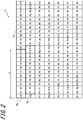
FIG. 2 is a diagram illustrating an example of a display panel illustrated inFIG. 1 viewed from a depth direction; -
FIG. 3 is a diagram illustrating an example of a parallax barrier illustrated inFIG. 1 viewed from the depth direction; -
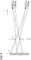
FIG. 4 is a diagram illustrating subpixels that are visible according to the position of eyes; -
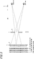
FIG. 5 is a diagram illustrating a calibration image included in an image of each eye in the first embodiment; -
FIG. 6 is a diagram illustrating an example of a captured image generated by an imaging device; -
FIG. 7 is a diagram illustrating an example of an image of each eye on which a calibration image is projected in the first embodiment; -
FIG. 8 is a diagram illustrating another example of an image of each eye on which a calibration image is projected in the first embodiment; -
FIG. 9 is a flowchart illustrating an example of a processing flow of the three-dimensional display device according to the first embodiment; -
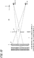
FIG. 10 is a diagram illustrating a calibration image projected on each eye in a second embodiment; -
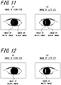
FIG. 11 is a diagram illustrating an example of an image of each eye on which a calibration image is projected in the second embodiment; -
FIG. 12 is a diagram illustrating another example of an image of each eye on which a calibration image is projected in the second embodiment; -
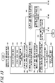
FIG. 13 is a flowchart illustrating an example of a processing flow of a three-dimensional display device according to the second embodiment; -
FIG. 14 is a diagram of a schematic configuration of the three-dimensional display device when an optical element is a lenticular lens; -
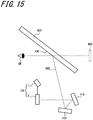
FIG. 15 is a diagram illustrating an example of a HUD equipped with the three-dimensional display system illustrated inFIG. 1 ; and -
FIG. 16 is a diagram illustrating an example of a moving object equipped with the HUD illustrated infig. 15 . - In order for a user to properly view an image projected by a three-dimensional display device, it is desired that image light appropriately reaches the position of eyes of a user.
- The disclosure provides a three-dimensional display device, a head-up display system, a moving object, and a program that are able to make a user view an appropriate three-dimensional image.
- Hereinafter, embodiments of the disclosure will be described with reference to drawings. The figures used in the following description are schematic, and the dimensional ratios and the like on the drawings do not always match actual ones.
- As illustrated in
FIG. 1 , a three-dimensional display system 100 according to a first embodiment of the disclosure includes animaging device 1 and a three-dimensional display device 2. - The
imaging device 1 is placed so that both eyes of a user are included in an image capturing range. Theimaging device 1 can be attached to an arbitrary position where the image of both eyes of the user can be captured. In the case where the three-dimensional display system 100 is attached to a movingobject 20, for example, theimaging device 1 may be attached to a rearview mirror of the movingobject 20. Theimaging device 1 may be attached to an instrument panel of the movingobject 20, for example, in a cluster. Theimaging device 1 may be attached to a center panel. Theimaging device 1 may be attached to a support portion of a steering wheel. - The
imaging device 1 may include, for example, a CCD (Charge Coupled Device) imaging element or a CMOS (Complementary Metal Oxide Semiconductor) imaging element. Theimaging device 1 is configured to generate an image by capturing an image of the user seated in the movingobject 20. Theimaging device 1 is configured to transmit the generated image to the three-dimensional display device 2. - As illustrated in
FIG. 1 , the three-dimensional display device 2 can include acommunication unit 3, acontroller 4, anirradiator 5, adisplay panel 6, and aparallax barrier 7 as an optical element. - The
communication unit 3 can communicate with theimaging device 1. The communication method used in the communication with theimaging device 1 by thecommunication unit 3 may be a wireless communication standard, a wireless communication standard for connecting to a mobile telephone network, a wireless communication standard, or a wired communication standard. The shortrange wireless communication standard may include, for example, Wi-Fi (registered trademark), Bluetooth (registered trademark), infrared rays, NFC (Near Field Communication), and the like. The wireless communication standard for connecting to the mobile telephone network may include, for example, LTE (Long Term Evolution), fourth-generation mobile communication systems, fifthgeneration mobile communication systems, and the like. - The
communication unit 3 is configured to receive an image generated by theimaging device 1 from theimaging device 1. - The
controller 4 is connected to each component of the three-dimensional display device 2 to control each component. The components controlled by thecontroller 4 include thecommunication unit 3 and thedisplay panel 6. Thecontroller 4 is configured as, for example, a processor. Thecontroller 4 may include one or more processors. The processor may include a general-purpose processor that loads a specific program and executes a specific function, and a dedicated processor specialized for a specific type of processing. The dedicated processor may include an application specific integrated circuit (ASIC). The processor may include a programmable logic device (PLD). The PLD may include an FPGA (Field-Programmable Gate Array). Thecontroller 4 may be either a SoC (System-on-a-Chip) or a SiP (System In a Package) in which one or more processors cooperate. - The
controller 4 is configured to carry out various kinds of processing based on an image captured by theimaging device 1 and received by thecommunication unit 3. The details of the processing of thecontroller 4 will be described later. - The
irradiator 5 is configured to be able to planarly irradiate thedisplay panel 6. Theirradiator 5 may include a light source, a light guide plate, a diffusion plate, a diffusion sheet, and the like. Theirradiator 5 is configured to emit irradiation light from the light source and to homogenize the irradiation light in the plane direction of thedisplay panel 6 by the light guide plate, the diffusion plate, the diffusion sheet, or the like. Then, theirradiator 5 can emit the homogenized light toward thedisplay panel 6. - As the
display panel 6, a display panel such as a transmissive liquid crystal display panel may be adopted. Thedisplay panel 6 is not limited to the transmissive liquid crystal panel, and other display panels such as organic EL can be used. In the case where a self-luminous display panel is used as thedisplay panel 6, the three-dimensional display device 2 does not need to include theirradiator 5. Thedisplay panel 6 will be described as a liquid crystal panel. - As illustrated in
FIG. 2 , thedisplay panel 6 includes a plurality of divided regions on anactive area 61 formed in a planar shape. Theactive area 61 can display a parallax image. The parallax image includes a left-eye image (first image) and a right-eye image (second image) having parallax with respect to the left-eye image. The left-eye image is an image that is to be viewed with a left eye (first eye) of the user. The right-eye image is an image that is to be viewed with the left eye (second eye) of the user. A divided region is a region divided in a first direction and a second direction that intersects the first direction. A direction orthogonal to the first and second directions is referred to as a third direction. The first direction may be referred to as a horizontal direction. The second direction may be referred to as a vertical direction. The third direction may be referred to as a depth direction. However, the first direction, the second direction, and the third direction are not limited thereto, respectively. In the drawing, the first direction is represented as an x-axis direction, the second direction is represented as a y-axis direction, and the third direction is represented as a z-axis direction. - Each divided region corresponds to one subpixel. Therefore, the
active area 61 includes a plurality of subpixels arranged in a grid along the horizontal and vertical directions. - Each subpixel corresponds to any color of R (Red), G (Green), B (Blue), and one pixel can be formed of three subpixels of R, G, and B as a set. One pixel can be referred to as one picture element. The
display panel 6 is not limited to the transmissive liquid crystal panel, and other display panels such as organic EL can be used. In the case where a self-luminous display panel is used as thedisplay panel 6, the three-dimensional display device 2 does not need to include theirradiator 5. - The plurality of subpixels arranged in the
active area 61 as mentioned above constitute a subpixel group Pg. The subpixel groups Pg are repeatedly arranged in the horizontal direction. The subpixel groups Pg can be arranged at the same position in the vertical direction and can be arranged to be shifted. For example, the subpixel groups Pg can be repeatedly arranged in the vertical direction to be adjacent to positions shifted by one subpixel in the horizontal direction. The subpixel group Pg includes subpixels in predetermined rows and columns. For example, the subpixel group Pg includes (2 × n × b) subpixels P1 to P(2×n×b) in which b subpixels (b rows) in the vertical direction and 2 × n (2 × n columns) subpixels in the horizontal direction are continuously arranged. In the example illustrated inFIG. 3 , n = 6 and b = 1. In theactive area 61, the subpixel group Pg including twelve subpixels P1 to P12 in which one subpixel in the vertical direction and twelve subpixels in the horizontal direction are continuously arranged is disposed. In the example illustrated inFIG. 3 , reference numerals are given to some subpixel group Pg. - The subpixel group Pg is a minimum unit in which the
controller 4 described below carries out control to display an image. The subpixels included in the subpixel group Pg are identified with identification information P1 to P(2×n×b). The subpixels P1 to P(2×n×b) that have the same identification information of the whole subpixel group Pg are controlled substantially simultaneously by thecontroller 4. For example, in the case where an image displayed at the subpixel P1 is switched from a left-eye image to a right-eye image, thecontroller 4 simultaneously switches the image displayed at the subpixel P1 in the whole subpixel group Pg from the left-eye image to the right-eye image. - As illustrated in
FIG. 1 , theparallax barrier 7 is formed in a planar shape along theactive area 61, and is disposed away by a predetermined distance (gap) g from theactive area 61. Theparallax barrier 7 may be positioned on an opposite side of theirradiator 5 with respect to thedisplay panel 6. Theparallax barrier 7 may be positioned on the irradiator 5-side with respect to thedisplay panel 6. - As illustrated in
FIG. 3 , theparallax barrier 7 is configured to define a propagation direction of the image light emitted from the subpixels for each of light-transmittingregions 71 which are a plurality of strip regions extending in a predetermined direction in the plane. Specifically, theparallax barrier 7 includes a plurality ofdimming regions 72 in which the image light is dimmed. The plurality ofdimming regions 72 partition the light-transmittingregions 71 between theadjacent dimming regions 72. The light-transmittingregion 71 has higher light transmittance than that of thedimming region 72. Thedimming region 72 has lower light transmittance than that of the light-transmittingregion 71. The light-transmittingregion 71 and thedimming region 72 extend in a predetermined direction along theactive area 61 and are alternately arranged repeatedly in a direction perpendicular to the predetermined direction. The predetermined direction is, for example, a direction along a diagonal line of the subpixels. The predetermined direction can be set to a direction which crosses b subpixels in the second direction while crossing a subpixels in the first direction (where a and b are positive relatively prime integers). The predetermined direction may be the second direction. - By defining the propagation direction of the image light emitted from the subpixels arranged in an active area A, the
parallax barrier 7 is configured to transmit the image light emitted from a part of the subpixels of theactive area 61 through the light-transmittingregions 71 and propagate the image light to the left eye of the user. Theparallax barrier 7 is configured to propagate the image light emitted from some other subpixels of theactive area 61 through the light-transmittingregions 71 and propagate the image light to the right eye of the user. - As illustrated in
FIG. 1 , the region of the active area A that is visible with each eye of the user is determined based on the characteristics of the three-dimensional display device 2 and the position of the eyes of the user. The characteristics of the three-dimensional display device 2 are the gap g, an image pitch k, which is the horizontal length of the subpixel group Pg, and a barrier pitch Bp, which is the sum of the horizontal lengths of the light-transmittingregion 71 and thedimming region 72. Hereinafter, the region of the active area A that can be viewed with the left eye by the image light being propagated to the position of the left eye of the user is referred to as a left visible region 61aL (first visible region). The region of the active area A that can be viewed with the right eye by the image light being propagated to the position of the right eye of the user is referred to as a right visible region 61aR (second visible region). - Here, the
controller 4 of the three-dimensional display device 2 will be described in detail. - The left visible region 61aL and the right visible region 61aR change according to the position of the eyes of the user. In the example illustrated in
FIG. 4 , before the change of the position of the eyes, the subpixels P3 to P8 are the left visible region 61aL, and the subpixels P9 to P12, P1, and P2 are the right visible region 61aR. After the change of the position of the eyes, the subpixels P4 to P9 are the left visible region 61aL, and the subpixels P10 to 12 and P1 to P3 are the right visible region 61aR. - Therefore, before the change, when the
controller 4 causes the subpixels P3 to P8 to display the left-eye image and causes the subpixels P9 to P12, P1, and P2 to display the right-eye image, the user can view a three-dimensional image with the least crosstalk. However, when, after the position of the eyes is changed in the horizontal direction, thecontroller 4 carries out control such that the left-eye image and the right-eye image are displayed on thedisplay panel 6 in the same manner as before the change, the left eye views more of the right-eye image, and the right eye views more of the left-eye image than before the change. As a result, crosstalk increases, and it is difficult for the user to properly view the three-dimensional image. Therefore, thecontroller 4 needs to determine a left display subpixel (first display subpixel) that is visible with the left eye and a right display subpixel (second display subpixel) that is visible with the right eye so that the occurrence of crosstalk is reduced even after the position of the eyes is changed. - To this end, the
controller 4 causes each subpixel of thedisplay panel 6 to display a calibration image in a calibration mode. Thecontroller 4 causes thedisplay panel 6 to display a parallax image in a normal mode, based on the cornea image in the captured image generated by theimaging device 1 when the calibration image is displayed. Hereinafter, the details of the processing of thecontroller 4 in each of the calibration mode and the normal mode will be described. - In the calibration mode, the
controller 4 causes thedisplay panel 6 to display a calibration pattern. Specifically, thecontroller 4 causes thedisplay panel 6 to display one of the (2 × n) types of calibration patterns. The calibration pattern is a pattern of display positions on thedisplay panel 6 of a first calibration image that is to be viewed with the left eye and a second calibration image that is to be viewed with the right eye. The first calibration image may be, for example, a white image whose brightness is higher than a predetermined value close to the maximum brightness (for example, brightness 250 at 256 gradations) and is indicated by "W" in the drawing. The second calibration image may be, for example, a black image whose brightness is lower than a predetermined value close to the minimum brightness (for example, brightness 10 at 256 gradations) and is indicated by "BL" in the drawing. - Hereinafter, each of the (2 × n) types of calibration patterns will be described as a k-th calibration pattern (k = 1 to (2 × n)). As illustrated in
FIG. 5 , a first calibration pattern is a pattern in which the first calibration image is displayed on the subpixels P1 to P6 and the second calibration image is displayed on the subpixels P7 to P12. The second calibration pattern is a pattern in which the first calibration image is displayed on the subpixels P2 to P7 and the second calibration image is displayed on the subpixels P8 to P12, and P1. In this way, in the k-th calibration pattern, the first calibration image is displayed on n subpixels continuous in one direction from a subpixel Pk, and the second calibration image is displayed on the remaining subpixels. - Hereinafter, the first calibration image will be referred to as a white image, and the second calibration image will be referred to as a black image.
- The
controller 4 extracts the cornea image of each of the left eye and the right eye of the user from the captured image as illustrated inFIG. 6 , received by thecommunication unit 3. The method by which thecontroller 4 extracts the cornea image may be any method. For example, thecontroller 4 may extract the cornea image by pattern matching. Thecontroller 4 may detect the image of a face of the user by pattern matching and extract the cornea image, based on the relative positional relationship between the image of the face and the image of the cornea. - The
controller 4 determines one of the calibration patterns as a reference pattern, based on the cornea image of each eye in the captured image. The reference pattern is a pattern for controlling the image displayed on thedisplay panel 6 by thecontroller 4 in the normal mode so that the user can view the three-dimensional image with the crosstalk reduced. In the calibration pattern determined as a reference pattern, thecontroller 4 causes the subpixels of thedisplay panel 6 on which a white image was displayed, to display the left-eye image in the normal mode. In the calibration pattern determined as the reference pattern, thecontroller 4 causes the subpixels of thedisplay panel 6 on which the black image was displayed, to display the right-eye image in the normal mode. - Specifically, the
controller 4 extracts the central area of the cornea of each of the left eye and the right eye. The central area is an area smaller than the ellipse centered on the center of the ellipse formed by the cornea of the left eye. The central area may be, for example, an area within a rectangle having a predetermined ratio of the major axis and the minor axis of the ellipse formed by the cornea of the left eye as a long side and a short side, respectively. Thecontroller 4 determines whether or not the image of the white image and the image of the black image are included in the central area of the cornea of each of the left eye and the right eye. - The
controller 4 determines whether or not the image of the white image and the image of the black image are included in the central area of the cornea image of the right eye. More specifically, thecontroller 4 searches for the brightness values of the white image and the black image in the central area of the cornea image of the left eye by known image processing. Thecontroller 4 searches for the brightness values of the white image and the black image in the central area of the cornea image of the right eye by known image processing. In this way, thecontroller 4 determines whether or not the image of the first calibration image and the image of the second calibration image are included in the central area of the cornea image of the left eye and the right eye, respectively. - The
controller 4 causes theimaging device 1 to generate a captured image when the first calibration pattern is displayed on thedisplay panel 6. In the example illustrated inFIG. 5 , the first calibration pattern is a pattern in which a white image is displayed on the subpixels P1 to P6 and a black image is displayed on the subpixels P7 to P12. In this example, the cornea image of the left eye in the captured image includes both the image of the white image displayed in the subpixels P3 to P6 and the image of the black image displayed in the subpixels P7 to P8. The cornea image of the right eye in the captured image includes both the image of the black image displayed on the subpixels P9 to P12 and the image of the white image displayed on the subpixels P1 and P2. - Therefore, when the first calibration pattern is displayed on the
display panel 6, as illustrated inFIGS. 7(a) and 7(b) , the image of the white image and the image of the black image are included in the central area of the cornea image of each of the left eye and the right eye. Therefore, thecontroller 4 determines that the image of the white image and the image of the black image are included in the central area of the cornea image of the left eye and the right eye. By using this principle, thecontroller 4 can determine as a reference pattern of a calibration pattern in which only the image of the white image is included in the central area of the cornea image of the left eye and only the image of the black image is included in the central area of the cornea image of the right eye. - Specifically, the
controller 4 displays one of the calibration patterns on thedisplay panel 6. Thecontroller 4 determines whether or not the image of the white image and the image of the black image are included in the central area of the cornea image of the left eye in the image. As illustrated inFIG. 7(b) , when determining that the image of the white image and the image of the black image are included in the central area of the cornea image of the left eye in the image, thecontroller 4 causes thedisplay panel 6 to display another calibration pattern for which the determination has not been made. Thecontroller 4 causes thedisplay panel 6 to display another calibration pattern and repeats the same determination. - When determining that the image of the white image is included and the image of the black image is not included in the central area of the cornea image of the left eye, in the captured image as illustrated in
FIG. 8(b) , thecontroller 4 determines whether or not the image of the white image and the image of the black image are included in the central area of the cornea image of the right eye. As illustrated inFIG. 8(a) , when determining that the image of the black image is included and the image of the white image is not included in the central area of the cornea image of the right eye, thecontroller 4 determines the calibration pattern when the captured image is generated as a reference pattern. - In the example illustrated in
FIG. 5 , thecontroller 4 can control thedisplay panel 6 to display a third calibration pattern. The third calibration pattern is a pattern in which a white image is displayed on the subpixels P3 to P8 as the first calibration image and a black image is displayed on the subpixels P9 to P12, P1 and P2 as the second calibration image. At this time, thecontroller 4 determines that the image of the white image is included in the central area of the cornea image of the left eye and the image of the black image is not included, and the image of the black image is included in the central area of the cornea image of the right eye and the image of the white image is not included. Thecontroller 4 determines the third calibration pattern as the reference pattern. - In the normal mode, the
controller 4 causes thedisplay panel 6 to display a parallax image by using the reference pattern. Specifically, thecontroller 4 causes the subpixels on which a white image was displayed to display the left-eye image in the reference pattern. Thecontroller 4 causes the subpixels on which a black image was displayed to display the right-eye image in the reference pattern. - The processing executed by the
controller 4 in the first embodiment will be described in detail with reference toFIG. 9 . - The
controller 4 causes thedisplay panel 6 to display one of the (2 × n) types of calibration patterns (step S41). - When the calibration pattern is displayed in step S41, the
controller 4 acquires the image captured by theimaging device 1 during the display of the calibration pattern and received by the communication unit 3 (step S42) . - When the captured image is acquired in step S42, the
controller 4 extracts the cornea images of the left eye and the right eye from the captured image acquired in step S12 (step S43). - When the cornea image is extracted in step S43, the
controller 4 extracts the central area of the cornea image (step S44). - When the central area of the cornea image is extracted in step S44, the
controller 4 determines whether or not the image of the white image is included in the central area of the cornea image of the left eye extracted in step S44 (step S45). - When it is determined in step S45 that the image of the white image is included in the central area of the cornea image of the left eye, the
controller 4 determines whether or not the image of the black image is included in the central area of the cornea image of the left eye (step S46) . - When it is determined in step S46 that the image of the black image is not included in the central area of the cornea image of the left eye, the
controller 4 determines whether or not the image of the black image is included in the central area of the cornea image of the right eye (step S47). - When it is determined in step S47 that the image of the black image is included in the central area of the cornea image of the right eye, the
controller 4 determines whether or not the image of the white image is included in the central area of the cornea image of the right eye (step S48). - When it is determined in step S48 that the image of the white image is not included in the central area of the cornea image of the right eye, the controller 14 determines the calibration pattern displayed in step S41 as a reference pattern (step S49).
- When it is determined in step S45 that the image of the white image is not included in the central area of the cornea image of the left eye, the
controller 4 displays a calibration pattern different from the calibration pattern already displayed, on the display panel 6 (step S50). When it is determined in step S46 that the image of the black image is included in the central area of the cornea image of the left eye, thecontroller 4 causes thedisplay panel 6 to display a calibration pattern different from the calibration pattern already displayed (step S50). When it is determined in step S47 that the image of the black image is not included in the central area of the cornea image of the right eye, thecontroller 4 causes thedisplay panel 6 to display a calibration pattern different from the calibration pattern already displayed (step S50). When it is determined in step S48 that the image of the white image is included in the central area of the cornea image of the right eye, thecontroller 4 displays a calibration pattern different from the calibration pattern already displayed (step S50). - When a calibration pattern different from the calibration pattern already displayed is displayed on the
display panel 6 in step S50, the procedure returns to S42 and thecontroller 4 repeats the processing. - When a reference pattern is determined in step S49, the
controller 4 ends the calibration mode, and when a start instruction of the normal mode is inputted, thecontroller 4 carries out display of a parallax image based on the determined reference pattern. - Subsequently, a second embodiment of the disclosure will be described with reference to drawings. The three-
dimensional display system 100 according to the second embodiment includes animaging device 1 and a three-dimensional display device 2 as in the first embodiment. - The
imaging device 1 of the second embodiment is the same as theimaging device 1 of the first embodiment. The three-dimensional display device 2 of the second embodiment includes acommunication unit 3, acontroller 4, anirradiator 5, adisplay panel 6, and aparallax barrier 7, as in the first embodiment. Thecommunication unit 3, theirradiator 5, thedisplay panel 6, and theparallax barrier 7 are the same as those in the first embodiment. Thecontroller 4 of the second embodiment is connected to each component of the three-dimensional display device 2 and can control each component as in the first embodiment. Thecontroller 4 of the second embodiment is configured as a processor as in the first embodiment. The processing performed by thecontroller 4 of the second embodiment is different from that of the first embodiment, and the processing will be described in detail below. - The calibration images of the second embodiment are the same as the calibration image of the first embodiment. Hereinafter, for description, the first calibration image will be referred to as a white image, and the second calibration image will be referred to as a black image.
- In a calibration mode, the
controller 4 causes thedisplay panel 6 to display a calibration pattern. Specifically, as illustrated inFIG. 10 , thecontroller 4 causes any one of the (2 × n) subpixels included in each subpixel group to display a white image. Thecontroller 4 causes the subpixels that do not display a white image among the (2 × n) subpixels included in each subpixel group to display a black image. - The
controller 4 extracts the cornea images of the left eye and the right eye in the captured image received by thecommunication unit 3. The method by which thecontroller 4 extracts the cornea images is the same as that in the first embodiment. - The
controller 4 extracts the central area of the cornea of each of the left and right eyes. Thecontroller 4 determines whether or not the image of a first calibration image is included in the central area of the cornea of each of the left eye and the right eye. - When extracting the central area of the cornea image, the
controller 4 determines a left display subpixel, a right display subpixel, a left parallax subpixel (first parallax subpixel), and a left parallax subpixel (second parallax subpixel), based on the calibration image included in the central area. The left display subpixel is a subpixel that is visible with the left eye. The right display subpixel is a subpixel that is visible with the right eye. The left parallax subpixel is a subpixel that is visible with the left eye and not visible with the right eye. The right parallax subpixel is a subpixel that is visible with the right eye and not visible with the left eye. - Specifically, the
controller 4 determines whether or not the image of the white image is included in the central area of the cornea image of the left eye. When determining that the image of the white image is included in the central area of the cornea image of the left eye as illustrated inFIGS. 11(b) and 12(b) , thecontroller 4 determines that the subpixel displaying the white image is a left display subpixel. - When determining that the image of the white image is included in the central area of the cornea image of the left eye, the
controller 4 determines whether or not the image of the white image is included in the central area of the cornea image of the right eye. As illustrated inFIG. 11(a) , when determining that the image of the white image is included in the central area of the cornea image of the right eye, thecontroller 4 determines that the subpixel displaying the white image is a left display subpixel and a right display subpixel. As illustrated inFIG. 12(a) , when determining that the image of the white image is not included in the central area of the cornea image of the right eye, thecontroller 4 determines that the subpixel displaying the white image is a left parallax subpixel. - The
controller 4 determines whether or not the image of the white image is included in the central area of the cornea image of the right eye. As illustrated inFIG. 11(a) , when determining that the image of the white image is included in the central area of the cornea image of the right eye, thecontroller 4 determines that the subpixel displaying the white image is a right display subpixel. - When determining that the image of the white image is not included in the central area of the cornea image of the right eye, the
controller 4 determines whether or not the image of the white image is included in the central area of the cornea image of the left eye. When determining that the image of the white image is not included in the central area of the cornea image of the left eye, thecontroller 4 determines that the subpixel displaying the white image is a right parallax subpixel. - When determining that the image of the white image is included in neither the central area of the cornea image of the left eye nor the central area of the cornea image of the right eye, the
controller 4 determines that the subpixel displaying the white image is neither a left display subpixel nor a right display subpixel. - Subsequently, the
controller 4 causes any of the subpixels for which the above determination has not been made to display a white image and causes the subpixels not displaying a white image at this time to display a black image. Then, thecontroller 4 also determines whether the subpixel displaying the white image is a left display subpixel or a right display subpixel. Similarly, thecontroller 4 determines whether the subpixel displaying the white image is a left parallax subpixel or a right parallax subpixel. Thecontroller 4 repeats these processing for all the subpixels included in the subpixel group Pg. When thecontroller 4 ends the determination for each of all the subpixels, thecontroller 4 ends the calibration mode. - In the example illustrated in
FIG. 10 , when thecontroller 4 causes the subpixel P1 to display a white image and causes the subpixels P2 to P12 to display a black image as the second calibration image, a white image is included within the central area of the cornea image of the right eye. Therefore, thecontroller 4 determines that the subpixel P1 is a right display subpixel. When thecontroller 4 causes the subpixel P3 to display a white image and causes the subpixels P1, P2, and P4 to P12 to display a white image, a white image is included within the central area of the cornea image of the left eye. Therefore, thecontroller 4 determines that the subpixel P3 is a left display subpixel. - In a normal mode, the
controller 4 causes the left parallax subpixel determined in the calibration mode to display a left-eye image. In the normal mode, thecontroller 4 causes the right parallax subpixel determined in the calibration mode to display a right-eye image. Thecontroller 4 may cause the subpixel which is the left display subpixel determined in the calibration mode and is the right display subpixel, to display a black image. - The processing executed by the
controller 4 in the second embodiment will be described in detail with reference toFIG. 13 . - The
controller 4 causes any one of the subpixels in each subpixel group Pg, to display a white image and causes the subpixels other than the subpixel on which the white image is displayed, to display a black image (step S51) . - When a white image and a black image are displayed in step S51, the
controller 4 acquires the image captured by theimaging device 1 during the display and received by the communication unit 3 (step S52). - When the captured image is acquired in step S52, the
controller 4 extracts the cornea images of the left eye and the right eye from the captured image acquired in step S52 (step S53). - When the cornea image is extracted in step S53, the
controller 4 extracts the central area of the cornea image (step S54). - When the central area of the cornea image is extracted in
step 54, thecontroller 4 determines whether or not a white image is included in the central area of the cornea image of the left eye (step S55). - In step S55, when it is determined that the image of a white image is included in the central area of the cornea image of the left eye, the
controller 4 determines that the subpixel displaying the white image is a left display subpixel (step S56). - The
controller 4 determines whether or not the image of the white image is included in the central area of the cornea image of the right eye (step S57). - In step S57, when it is determined that the image of the white image is included in the central area of the cornea image of the right eye, the
controller 4 determines the subpixel displaying the white image as the left subpixel and the right subpixel (step S58). - When it is determined in step S57 that the image of the white image is not included in the central area of the cornea image of the right eye, the
controller 4 determines that the subpixel displaying the white image is a left parallax subpixel (step S59). - When it is determined in step S55 that the image of the white image is not included in the central area of the cornea image of the left eye, the
controller 4 determines whether or not the image of the white image is included in the central area of the cornea image of the right eye (step S60). - When it is determined in step S60 that the image of the white image is included in the central area of the cornea image of the right eye, the
controller 4 determines that the subpixel displaying the white image is a right parallax subpixel (step S61). - When the processing of steps S59 to S61 ends, the
controller 4 determines whether or not the determination for all the subpixels has been made (step S62). - When it is determined in step S62 that the determination has not been made for all the subpixels, the
controller 4 causes the other subpixels to display a white image (step S63). - When a white image is displayed in the other subpixels in step S63, the procedure returns to step S52 and the controller 22 repeats the processing.
- When it is determined in step S62 that the determination has been made for all the subpixels, the
controller 4 ends the calibration mode, and when a start instruction of the normal mode is inputted, thecontroller 4 carries out display of a parallax image based on the determination. - As the
controller 4 according to the above-described embodiment, an information processing device such as a computer can be adopted. Such an information processing device can be realized by storing a program describing processing contents that realize each function of thecontroller 4 according to the embodiments in the memory of the information processing device and reading and executing the program by a processor of the information processing device. Thecontroller 4 may be configured to read the program from a non-transitory computer-readable medium and implement the program. The non-transitory computer-readable medium includes, but are not limited to, magnetic storage media, optical storage media, photomagnetic storage media, and semiconductor storage media. Magnetic storage media include magnetic disks, hard disks, and magnetic tapes. Optical storage media include optical discs such as CD (Compact Disc), DVD, and Blu-ray disc (Blu-ray (registered trademark) Disc). Semiconductor storage media include a ROM (Read Only Memory), an EEPROM (Electrically Erasable Programmable Read-Only Memory), and a flash memory. - As described above, in the first embodiment, the
controller 4 determines, as a reference pattern, a calibration image displayed when an image is captured in which the white image is included in the cornea image of the left eye and the white image is not included in the cornea image of the right eye, and the black image is included in the cornea image of the right eye and the black image of the left eye is not included. Thecontroller 4 controls the parallax image which is to be displayed on thedisplay panel 6, based on the reference pattern in the normal mode. Therefore, thecontroller 4 causes the subpixels on which a white image is displayed to display the left-eye image, and causes the subpixels on which a black image is displayed to display the right-eye image, and the user views the left-eye image with the left eye and views the right-eye image with the right eye. Therefore, the user can properly view a three-dimensional image. - In the first embodiment, the
controller 4 determines whether or not a white image and a black image are included in the central area of the image of each eye. Humans tend to recognize the image of an object projected on the central area more strongly than the image of an object projected on the peripheral area of the cornea. Therefore, thecontroller 4 determines a calibration pattern based on the white image and the black image projected on the central area. Therefore, in the normal mode, the user can view the left-eye image in the central area of the left eye and view the right-eye in the central area of the right eye. In such a configuration, since the right-eye image may be viewed in the peripheral area of the left eye of the user, but it is difficult to be strongly recognized, the right-eye image viewed in the peripheral area of the left eye has little effect on the occurrence of crosstalk. By calibrating in this way, the area on the captured image in which thecontroller 4 determines whether or not each of a white image and a black image is included becomes smaller. Therefore, the processing load of thecontroller 4 can be reduced. - In the second embodiment, the
controller 4 displays an image on thedisplay panel 6. Thecontroller 4 determines a left display subpixel and a right display subpixel based on the cornea images of different parts of the calibration image in the captured image that are viewed with the left eye and the right eye of the user. For this reason, in the calibration mode before the three-dimensional display device 2 displays a three-dimensional image, the user does not need to confirm that a white image and a black image are viewed with the left eye and the right eye of the user, respectively. Therefore, the user's effort required for the setting can be reduced. - In the second embodiment, the
controller 4 determines a left parallax subpixel that is visible with the left eye and not visible with the right eye, and a right parallax subpixel that is visible with the right eye and not visible with the left eye. Therefore, thecontroller 4 causes the left parallax subpixel to display the left-eye image and causes the right parallax subpixel to display the right-eye image so that the user views the left-eye image only with the left eye and view the right-eye image only with the right eye. Therefore, the user can view a three-dimensional image with the crosstalk reduced. - In the second embodiment, the
controller 4 determines whether or not a white image is included in the central area of the image of each eye. Therefore, thecontroller 4 determines a left display subpixel, a right display subpixel, a left parallax subpixel, and a right parallax subpixel, based on the white image projected on the central area. Therefore, in the normal mode, the user can view the left-eye image in the central area of the left eye and view the right-eye in the central area of the right eye. Therefore, the processing load of thecontroller 4 can be reduced while reducing the influence on the occurrence of crosstalk. - Although the above embodiments have been described as representative examples, it will be apparent to those skilled in the art that many modifications and substitutions can be made within the spirit and scope of the invention. Therefore, the invention should not be construed as limiting by the embodiments described above, and various modifications and changes can be made without departing from the claims. For example, it is possible to combine the plurality of constituent blocks described in the embodiments and the examples into one, or to divide one constituent block.
- For example, in the above-described embodiments, the first calibration image may be a white image and the second calibration image may be a black image, but the invention is not limited thereto. For example, the first calibration image may be a black image and the second calibration image may be a white image. The first calibration image and the second calibration image only have different values indicating the characteristics of the images so that the part of the captured image of the eyes that include the first calibration image and the second calibration image can be distinguished. For example, the first calibration image may be a red image and the second calibration image may be a green image.
- For example, in the second embodiment, the
controller 4 determines whether or not a white image is included in the central area of the cornea image of the left eye and then determines whether or not a white image is included in the central area of the cornea image of the right eye, but the invention is not limited thereto. For example, thecontroller 4 may determine whether or not a white image is included in the central area of the cornea image of the right eye and then determine whether or not a white image is included in the central area of the cornea image of the left eye. - In each of the above-described embodiments, the three-
dimensional display device 2 includes theparallax barrier 7, but the invention is not limited to this. For example, the three-dimensional display device 2 may include a lenticular lens 8 as an optical element. In this case, the lenticular lens 8 is configured by arrangingcylindrical lenses 81 extending in the vertical direction in the horizontal direction on a plane as illustrated inFIG. 14 . Similar to theparallax barrier 7, the lenticular lens 8 propagates the image light emitted from the subpixels in a left visible region 71aL to the position of the right eye of the user and propagates the image light emitted from the subpixels in a visible region 71aR to the position of the left eye of the user. - As illustrated in
FIG. 15 , the three-dimensional display system 100 can be mounted on a head-updisplay system 400. The head-updisplay system 400 is also called an HUD (Head Up Display) 400. TheHUD 400 includes the three-dimensional display system 100, anoptical member 410, and a projectedmember 420 including a projectedsurface 430. TheHUD 400 causes the image light emitted from the three-dimensional display system 100 to reach the projectedmember 420 via theoptical member 410. TheHUD 400 causes the image light reflected by the projectedmember 420 to reach the left eye and the right eye of the user. That is, theHUD 400 advances the image light from the three-dimensional display system 100 to the left eye and the right eye of the user along anoptical path 440 indicated by the broken line. The user can view the image light that has arrived along theoptical path 440 as avirtual image 450. - As illustrated in
FIG. 14 , theHUD 400 including the three-dimensional display system 100 may be mounted on the movingobject 20. A part of the configuration of theHUD 400 may be shared with other devices and parts included in the movingobject 20. For example, in the movingobject 20, a windshield may also be used as the projectedmember 420. In the case where a part of the configuration is also shared with other devices or parts in the movingobject 20, the other configuration can be referred to as an HUD module or a three-dimensional display component. "Moving objects" in the disclosure include vehicles, ships, and aircraft. "Vehicles" in the disclosure include, but are not limited to, automobiles and industrial vehicles and may include railway vehicles, living vehicles, and fixed-wing aircraft traveling on runways. Automobiles include, but are not limited to, passenger cars, trucks, buses, motorcycles, trolley buses, and the like and may include other vehicles traveling on the road. The industrial vehicles include industrial vehicles for agriculture and construction. The industrial vehicles include, but are not limited to, forklifts and golf carts. The industrial vehicles for agriculture include, but are not limited to, tractors, tillers, transplanters, binders, combines, and lawnmowers. The industrial vehicles for construction include, but are not limited to, bulldozers, scrapers, excavators, crane trucks, dump trucks, and road rollers. The vehicles include those that run manually. The classification of vehicles is not limited to those described above. For example, an automobile may include an industrial vehicle capable of traveling on a road and the same vehicle may be included in a plurality of classifications. The ships in the disclosure include marine jets, boats, and tankers. The aircraft in the disclosure include fixed-wing aircraft and rotary-wing aircraft. -
- 1: Imaging device
- 2: Three-dimensional display device
- 3: Communication unit
- 4: Controller
- 5: Three-dimensional display device
- 5: Irradiator
- 6: Display panel
- 7: Parallax barrier
- 20: Moving object
- 61: Active area
- 61aL: Left visible region
- 61aR: Right visible region
- 61bL: Left dimming region
- 61bR: Right dimming region
- 71: Dimming region
- 72: Light-transmitting region
- 100: Three-dimensional display system
- 400: Head-up display system
- 410: Optical member
- 420: Projected member
- 440: Optical path
- 450: Virtual image
- Pg: Subpixel group
- P2 to P12: Subpixel
Claims (12)
- A three-dimensional display device, comprising:a display panel configured to display an image;an optical element configured to define a propagation direction of image light emitted from the display panel;a controller configured to control an image which is to be displayed on the display panel; anda communication unit configured to receive a captured image of first eye and second eye different from the first eye, of a user,the controller being configured so that a calibration image is displayed on the display panel and that, based on cornea images of different parts of the calibration image in the captured image that are viewed with the first eye and the second eye of the user, respectively, a first display subpixel on the display panel that is visible with the first eye is determined and a second display subpixel on the display panel that is visible with the second eye is determined.
- The three-dimensional display device according to claim 1, wherein
the controller is configured so that a first parallax subpixel that is visible with the first eye but not visible with the second eye, and a second parallax subpixel that is visible with the second eye but not visible with the first eye are determined. - The three-dimensional display device according to claim 2, wherein
the controller is configured to cause a first parallax subpixel to display a first image that is to be viewed with the first eye and cause a second parallax subpixel to display a second image that is to viewed with the second eye. - A three-dimensional display device, comprising:a display panel configured to display an image;an optical element configured to define a propagation direction of image light emitted from the display panel;a controller configured to control an image which is to be displayed on the display panel; anda communication unit configured to receive a captured image of first eye and second eye different from the first eye, of a user,when a pattern of display positions on the display panel of an image that is to be viewed with the first eye and an image that is to be viewed with the second eye is defined as a calibration pattern,the controller being configured so that a plurality of calibration patterns are displayed on the display panel, and that, based on cornea images of different parts of each of the calibration patterns in the captured image that are viewed with the first eye and the second eye of the user, respectively, a reference pattern as a reference for displaying a three-dimensional image from the plurality of calibration patterns is determined.
- The three-dimensional display device according to claim 4, wherein
the controller is configured so that a calibration pattern of the plurality of calibration patterns where in the cornea image of the first eye, the first calibration image is included and the second calibration image is not included and in the cornea image of the second eye, the second calibration image is included and the first calibration image is not included, is determined as the reference pattern. - The three-dimensional display device according to claim 4, wherein
the controller is configured to cause a subpixel in which a first calibration image is displayed in the reference pattern, to display a first image that is to be viewed with the first eye and cause a subpixel in which a second calibration image is displayed in the reference pattern, to display a second image that is to be viewed with the second eye. - A head-up display system, comprising:a three-dimensional display device comprisinga display panel configured to display an image,an optical element configured to define a propagation direction of image light emitted from the display panel,a controller configured to display the image, anda communication unit configured to receive a captured image of first eye and second eye different from the first eye, of a user,the controller being configured so that a calibration image is displayed on the display panel and that, based on cornea images of different parts of the calibration image in the captured image that are viewed with the first eye and the second eye of the user, respectively, a first display subpixel on the display panel that is visible with the first eye is determined and a second display subpixel on the display panel that is visible with the second eye is determined; andan optical member configured to reflect the image light emitted from the three-dimensional display device, toward the first eye or the second eye.
- A head-up display system, comprising:a three-dimensional display device comprisinga display panel configured to display an image,an optical element configured to define a propagation direction of image light emitted from the display panel,a controller configured to control an image which is to be displayed on the display panel, anda communication unit configured to receive a captured image of first eye and second eye different from the first eye, of a user,when a pattern of display positions on the display panel of an image that is to be viewed with the first eye and an image that is to be viewed with the second eye, is defined as a calibration pattern, the controller being configured so that a plurality of calibration patterns are displayed on the display panel and that, based on cornea images of different parts of each of the calibration patterns in the captured image that are viewed with the first eye and the second eye of the user, respectively, a reference pattern as a reference for displaying a three-dimensional image from the plurality of calibration patterns is determined; andan optical member configured to reflect the image light emitted from the three-dimensional display device, toward the first eye or the second eye.
- A moving object, comprising:a head-up display system comprisinga three-dimensional display device comprisinga display panel configured to display an image,an optical element configured to define a propagation direction of image light emitted from the display panel,a controller configured to display the image, anda communication unit configured to receive a captured image of first eye and second eye different from the first eye, of a user,the controller being configured so that a calibration image is displayed on the display panel and that, based on cornea images of different parts of the calibration image in the captured image that are viewed with the first eye and the second eye of the user, respectively, a first display subpixel on the display panel that is visible with the first eye is determined and a second display subpixel on the display panel that is visible with the second eye is determined; andan optical member configured to reflect the image light emitted from the three-dimensional display device, toward the first eye or the second eye.
- A moving object, comprising:a head-up display system comprisinga three-dimensional display device comprisinga display panel configured to display an image,an optical element configured to define a propagation direction of image light emitted from the display panel,a controller configured to control an image which is to be displayed on the display panel, anda communication unit configured to receive a captured image of first eye and second eye different from the first eye, of a user,when a pattern of display positions on the display panel of an image that is to be viewed with the first eye and an image that is to be viewed with the second eye, is defined as a calibration pattern, the controller being configured so that a plurality of calibration patterns are displayed on the display panel and that, based on cornea images of different parts of each of the calibration patterns in the captured image that are viewed with the first eye and the second eye of the user, respectively, a reference pattern as a reference for displaying a three-dimensional image from the plurality of calibration patterns is determined; andan optical member configured to reflect the image light emitted from the three-dimensional display device, toward the first eye or the second eye.
- A program executed by a three-dimensional display device comprising a display panel configured to display an image, an optical element configured to define a propagation direction of image light emitted from the display panel, a controller configured to display the image, and a communication unit configured to receive a captured image of first eye and second eye different from the first eye, of a user,
the controller causing the display panel to display a calibration image, and based on cornea images of different parts of the calibration image in the captured image that are viewed with the first eye and second eye of the user, respectively, the controller determining a first display subpixel on the display panel that is visible with the first eye and determining a second display subpixel on the display panel that is visible with the second eye. - A program executed by a three-dimensional display device comprising a display panel configured to display an image, an optical element configured to define a propagation direction of image light emitted from the display panel, a controller configured to display the image, and a communication unit configured to receive a captured image of first eye and second eye different from the first eye, of a user,
when a pattern of display positions on the display panel of an image that is to be viewed with the first eye and an image that is to be viewed with the second eye, is defined as a calibration pattern, the controller causing the display panel to display a plurality of calibration patterns, and based on cornea images of different parts of each of the calibration patterns in the captured image that are viewed with the first eye and the second eye of the user, respectively, the controller determining a reference pattern as a reference for displaying a three-dimensional image from the plurality of calibration patterns.
Applications Claiming Priority (2)
| Application Number | Priority Date | Filing Date | Title |
|---|---|---|---|
| JP2018208331A JP7207954B2 (en) | 2018-11-05 | 2018-11-05 | 3D display device, head-up display system, moving object, and program |
| PCT/JP2019/042643 WO2020095801A1 (en) | 2018-11-05 | 2019-10-30 | Three-dimensional display device, head-up display system, mobile unit, and program |
Publications (2)
| Publication Number | Publication Date |
|---|---|
| EP3879823A1 true EP3879823A1 (en) | 2021-09-15 |
| EP3879823A4 EP3879823A4 (en) | 2022-07-20 |
Family
ID=70611810
Family Applications (1)
| Application Number | Title | Priority Date | Filing Date |
|---|---|---|---|
| EP19880989.9A Withdrawn EP3879823A4 (en) | 2018-11-05 | 2019-10-30 | Three-dimensional display device, head-up display system, mobile unit, and program |
Country Status (5)
| Country | Link |
|---|---|
| US (1) | US11470302B2 (en) |
| EP (1) | EP3879823A4 (en) |
| JP (1) | JP7207954B2 (en) |
| CN (1) | CN112970248A (en) |
| WO (1) | WO2020095801A1 (en) |
Families Citing this family (5)
| Publication number | Priority date | Publication date | Assignee | Title |
|---|---|---|---|---|
| JP7536693B2 (en) * | 2020-07-22 | 2024-08-20 | 京セラ株式会社 | Three-dimensional display device, head-up display and mobile body |
| CN116194823A (en) * | 2020-07-22 | 2023-05-30 | 京瓷株式会社 | Three-dimensional display device, head-up display, and moving object |
| US12388970B2 (en) * | 2021-05-28 | 2025-08-12 | Kyocera Corporation | Method for setting three-dimensional image display system |
| CN117461310A (en) * | 2021-06-02 | 2024-01-26 | 京瓷株式会社 | Setting method of three-dimensional image display system |
| WO2025205416A1 (en) * | 2024-03-28 | 2025-10-02 | ソニーグループ株式会社 | Display control device and calibration method |
Family Cites Families (23)
| Publication number | Priority date | Publication date | Assignee | Title |
|---|---|---|---|---|
| JP3668116B2 (en) | 1999-09-24 | 2005-07-06 | 三洋電機株式会社 | 3D image display device without glasses |
| EP1087627A3 (en) | 1999-09-24 | 2004-02-18 | SANYO ELECTRIC Co., Ltd. | Autostereoscopic image display device |
| JP3454798B2 (en) * | 2001-04-27 | 2003-10-06 | 三洋電機株式会社 | Setting method of head position detecting device in stereoscopic image display device and head position detecting device |
| JP2006308674A (en) * | 2005-04-26 | 2006-11-09 | Mitsubishi Electric Corp | Image display device |
| KR101073512B1 (en) * | 2010-05-20 | 2011-10-17 | 한국과학기술연구원 | 3D image display device using gamut extension |
| JP5699686B2 (en) * | 2011-02-28 | 2015-04-15 | 大日本印刷株式会社 | Method for manufacturing columnar lens sheet for stereoscopic image display |
| US9081195B2 (en) * | 2012-08-13 | 2015-07-14 | Innolux Corporation | Three-dimensional image display apparatus and three-dimensional image processing method |
| KR101364883B1 (en) * | 2012-11-14 | 2014-02-27 | 서울과학기술대학교 산학협력단 | Crosstalk reduction method for 3d steroscopic image and crosstalk reduction apparatus for 3d steroscopic image |
| JP2014103585A (en) * | 2012-11-21 | 2014-06-05 | Toshiba Corp | Stereoscopic image display device |
| WO2014118391A2 (en) * | 2013-02-04 | 2014-08-07 | Dnv Gl Se | Inspection camera unit, method for inspecting interiors, and sensor unit |
| CN104113680B (en) * | 2013-04-19 | 2019-06-28 | 北京三星通信技术研究有限公司 | Gaze tracking system and method |
| CN103356163B (en) * | 2013-07-08 | 2016-03-30 | 东北电力大学 | Based on fixation point measuring device and the method thereof of video image and artificial neural network |
| WO2015021544A1 (en) * | 2013-08-11 | 2015-02-19 | NanoMedia Solutions Inc. | Nano-media information carrier based on pixelated nano-structures combined with an intensity control layer |
| CN104090659B (en) * | 2014-07-08 | 2017-04-05 | 重庆金瓯科技发展有限责任公司 | Operating pointer based on eye image and Eye-controlling focus indicates control device |
| US20160139422A1 (en) * | 2014-11-13 | 2016-05-19 | Innolux Corporation | Three-dimensional image display apparatus |
| KR102370062B1 (en) * | 2014-11-24 | 2022-03-04 | 삼성전자주식회사 | Method of determining calibration parameter for 3d display device and 3d display device thereof |
| ES2771855T3 (en) * | 2015-03-20 | 2020-07-07 | Nintendo Co Ltd | Method and apparatus for calibrating an autostereoscopic display device |
| US10373297B2 (en) * | 2016-10-26 | 2019-08-06 | Valve Corporation | Using pupil location to correct optical lens distortion |
| JP6665077B2 (en) * | 2016-12-07 | 2020-03-13 | 京セラ株式会社 | Image projection device, image display device, and moving object |
| JP6821454B2 (en) * | 2017-01-27 | 2021-01-27 | 公立大学法人大阪 | 3D display system, head-up display system, and mobile |
| CN106773091B (en) * | 2017-02-06 | 2019-05-03 | 京东方科技集团股份有限公司 | 3D display device and its working method |
| WO2019212635A1 (en) * | 2018-05-04 | 2019-11-07 | Harman International Industries, Incorporated | Reconfigurable optics for multi-plane heads-up displays |
| US10725302B1 (en) * | 2018-11-02 | 2020-07-28 | Facebook Technologies, Llc | Stereo imaging with Fresnel facets and Fresnel reflections |
-
2018
- 2018-11-05 JP JP2018208331A patent/JP7207954B2/en active Active
-
2019
- 2019-10-30 WO PCT/JP2019/042643 patent/WO2020095801A1/en not_active Ceased
- 2019-10-30 EP EP19880989.9A patent/EP3879823A4/en not_active Withdrawn
- 2019-10-30 CN CN201980073176.0A patent/CN112970248A/en active Pending
- 2019-10-30 US US17/290,818 patent/US11470302B2/en active Active
Also Published As
| Publication number | Publication date |
|---|---|
| US20210377513A1 (en) | 2021-12-02 |
| EP3879823A4 (en) | 2022-07-20 |
| JP7207954B2 (en) | 2023-01-18 |
| US11470302B2 (en) | 2022-10-11 |
| WO2020095801A1 (en) | 2020-05-14 |
| JP2020077913A (en) | 2020-05-21 |
| CN112970248A (en) | 2021-06-15 |
Similar Documents
| Publication | Publication Date | Title |
|---|---|---|
| US11470302B2 (en) | Three-dimensional display device, head-up display system, moving object, and non-transitory computer-readable medium storing program | |
| US11616940B2 (en) | Three-dimensional display device, three-dimensional display system, head-up display, and mobile object | |
| WO2019009243A1 (en) | Three-dimensional display device, three-dimensional display system, mobile body, and three-dimensional display method | |
| WO2021106689A1 (en) | Head-up display system and moving body | |
| WO2021090956A1 (en) | Head-up display, head-up display system, and moving body | |
| WO2018199185A1 (en) | Display device, display system, and mobile body | |
| US11442269B2 (en) | 3D display device, head-up display, moving body, and program | |
| WO2022131137A1 (en) | Three-dimensional display device, image display system, and moving body | |
| WO2022019154A1 (en) | Three-dimensional display device | |
| EP3988990B1 (en) | Head-up display, head-up display system, mobile object, and design method for head-up display | |
| EP3876529B1 (en) | Communication head up display system, communication device, mobile body, and program | |
| EP3876224B1 (en) | Radio communication head-up display system, radio communication equipment, moving body, and program | |
| JP7274392B2 (en) | Cameras, head-up display systems, and moving objects | |
| JP7618381B2 (en) | Three-dimensional display device, three-dimensional display system and mobile body | |
| WO2022149599A1 (en) | Three-dimensional display device |
Legal Events
| Date | Code | Title | Description |
|---|---|---|---|
| STAA | Information on the status of an ep patent application or granted ep patent |
Free format text: STATUS: THE INTERNATIONAL PUBLICATION HAS BEEN MADE |
|
| PUAI | Public reference made under article 153(3) epc to a published international application that has entered the european phase |
Free format text: ORIGINAL CODE: 0009012 |
|
| STAA | Information on the status of an ep patent application or granted ep patent |
Free format text: STATUS: REQUEST FOR EXAMINATION WAS MADE |
|
| 17P | Request for examination filed |
Effective date: 20210504 |
|
| AK | Designated contracting states |
Kind code of ref document: A1 Designated state(s): AL AT BE BG CH CY CZ DE DK EE ES FI FR GB GR HR HU IE IS IT LI LT LU LV MC MK MT NL NO PL PT RO RS SE SI SK SM TR |
|
| DAV | Request for validation of the european patent (deleted) | ||
| DAX | Request for extension of the european patent (deleted) | ||
| REG | Reference to a national code |
Ref country code: DE Ref legal event code: R079 Free format text: PREVIOUS MAIN CLASS: H04N0013125000 Ipc: H04N0013310000 |
|
| A4 | Supplementary search report drawn up and despatched |
Effective date: 20220622 |
|
| RIC1 | Information provided on ipc code assigned before grant |
Ipc: H04N 9/31 20060101ALN20220615BHEP Ipc: B60K 35/00 20060101ALN20220615BHEP Ipc: G02B 27/01 20060101ALN20220615BHEP Ipc: H04N 13/125 20180101ALI20220615BHEP Ipc: H04N 13/366 20180101ALI20220615BHEP Ipc: H04N 13/327 20180101ALI20220615BHEP Ipc: H04N 13/31 20180101AFI20220615BHEP |
|
| P01 | Opt-out of the competence of the unified patent court (upc) registered |
Effective date: 20230505 |
|
| STAA | Information on the status of an ep patent application or granted ep patent |
Free format text: STATUS: THE APPLICATION HAS BEEN WITHDRAWN |
|
| 18W | Application withdrawn |
Effective date: 20240730 |