EP3879809A1 - Device for an image acquisition system, image acquisition system and vehicle - Google Patents
Device for an image acquisition system, image acquisition system and vehicle Download PDFInfo
- Publication number
- EP3879809A1 EP3879809A1 EP21160790.8A EP21160790A EP3879809A1 EP 3879809 A1 EP3879809 A1 EP 3879809A1 EP 21160790 A EP21160790 A EP 21160790A EP 3879809 A1 EP3879809 A1 EP 3879809A1
- Authority
- EP
- European Patent Office
- Prior art keywords
- vehicle
- main body
- image acquisition
- acquisition unit
- apertures
- Prior art date
- Legal status (The legal status is an assumption and is not a legal conclusion. Google has not performed a legal analysis and makes no representation as to the accuracy of the status listed.)
- Granted
Links
- 239000012530 fluid Substances 0.000 claims description 22
- 239000004676 acrylonitrile butadiene styrene Substances 0.000 claims description 6
- 239000000853 adhesive Substances 0.000 claims description 4
- 230000001070 adhesive effect Effects 0.000 claims description 4
- 239000000463 material Substances 0.000 claims description 4
- 239000004677 Nylon Substances 0.000 claims description 3
- 229920002302 Nylon 6,6 Polymers 0.000 claims description 3
- 229920000122 acrylonitrile butadiene styrene Polymers 0.000 claims description 3
- 239000011521 glass Substances 0.000 claims description 3
- 230000007246 mechanism Effects 0.000 claims description 3
- 229920001778 nylon Polymers 0.000 claims description 3
- 230000003287 optical effect Effects 0.000 claims description 3
- 239000004417 polycarbonate Substances 0.000 claims description 3
- 229920000515 polycarbonate Polymers 0.000 claims description 3
- 239000000356 contaminant Substances 0.000 description 21
- 230000015654 memory Effects 0.000 description 16
- 238000000034 method Methods 0.000 description 8
- 239000012790 adhesive layer Substances 0.000 description 4
- 238000004891 communication Methods 0.000 description 4
- 238000004140 cleaning Methods 0.000 description 3
- 230000008569 process Effects 0.000 description 3
- XLYOFNOQVPJJNP-UHFFFAOYSA-N water Substances O XLYOFNOQVPJJNP-UHFFFAOYSA-N 0.000 description 3
- IJGRMHOSHXDMSA-UHFFFAOYSA-N Atomic nitrogen Chemical compound N#N IJGRMHOSHXDMSA-UHFFFAOYSA-N 0.000 description 2
- 238000010276 construction Methods 0.000 description 2
- 238000001514 detection method Methods 0.000 description 2
- 239000000428 dust Substances 0.000 description 2
- 230000007613 environmental effect Effects 0.000 description 2
- 230000006870 function Effects 0.000 description 2
- 230000002093 peripheral effect Effects 0.000 description 2
- 102100034112 Alkyldihydroxyacetonephosphate synthase, peroxisomal Human genes 0.000 description 1
- 101000799143 Homo sapiens Alkyldihydroxyacetonephosphate synthase, peroxisomal Proteins 0.000 description 1
- 230000006978 adaptation Effects 0.000 description 1
- 230000002411 adverse Effects 0.000 description 1
- 238000000848 angular dependent Auger electron spectroscopy Methods 0.000 description 1
- 230000005540 biological transmission Effects 0.000 description 1
- 238000007664 blowing Methods 0.000 description 1
- 239000007789 gas Substances 0.000 description 1
- 238000003384 imaging method Methods 0.000 description 1
- 230000002452 interceptive effect Effects 0.000 description 1
- 230000031700 light absorption Effects 0.000 description 1
- 230000003137 locomotive effect Effects 0.000 description 1
- 238000012986 modification Methods 0.000 description 1
- 230000004048 modification Effects 0.000 description 1
- 229910052757 nitrogen Inorganic materials 0.000 description 1
- 210000003733 optic disk Anatomy 0.000 description 1
- 230000000704 physical effect Effects 0.000 description 1
- 239000007921 spray Substances 0.000 description 1
- -1 such as Substances 0.000 description 1
- 239000000725 suspension Substances 0.000 description 1
- 230000000007 visual effect Effects 0.000 description 1
Images


Classifications
-
- G—PHYSICS
- G02—OPTICS
- G02B—OPTICAL ELEMENTS, SYSTEMS OR APPARATUS
- G02B5/00—Optical elements other than lenses
- G02B5/003—Light absorbing elements
-
- G—PHYSICS
- G03—PHOTOGRAPHY; CINEMATOGRAPHY; ANALOGOUS TECHNIQUES USING WAVES OTHER THAN OPTICAL WAVES; ELECTROGRAPHY; HOLOGRAPHY
- G03B—APPARATUS OR ARRANGEMENTS FOR TAKING PHOTOGRAPHS OR FOR PROJECTING OR VIEWING THEM; APPARATUS OR ARRANGEMENTS EMPLOYING ANALOGOUS TECHNIQUES USING WAVES OTHER THAN OPTICAL WAVES; ACCESSORIES THEREFOR
- G03B11/00—Filters or other obturators specially adapted for photographic purposes
- G03B11/04—Hoods or caps for eliminating unwanted light from lenses, viewfinders or focusing aids
- G03B11/045—Lens hoods or shields
-
- B—PERFORMING OPERATIONS; TRANSPORTING
- B60—VEHICLES IN GENERAL
- B60R—VEHICLES, VEHICLE FITTINGS, OR VEHICLE PARTS, NOT OTHERWISE PROVIDED FOR
- B60R11/00—Arrangements for holding or mounting articles, not otherwise provided for
- B60R11/04—Mounting of cameras operative during drive; Arrangement of controls thereof relative to the vehicle
-
- G—PHYSICS
- G02—OPTICS
- G02B—OPTICAL ELEMENTS, SYSTEMS OR APPARATUS
- G02B27/00—Optical systems or apparatus not provided for by any of the groups G02B1/00 - G02B26/00, G02B30/00
- G02B27/0006—Optical systems or apparatus not provided for by any of the groups G02B1/00 - G02B26/00, G02B30/00 with means to keep optical surfaces clean, e.g. by preventing or removing dirt, stains, contamination, condensation
-
- G—PHYSICS
- G03—PHOTOGRAPHY; CINEMATOGRAPHY; ANALOGOUS TECHNIQUES USING WAVES OTHER THAN OPTICAL WAVES; ELECTROGRAPHY; HOLOGRAPHY
- G03B—APPARATUS OR ARRANGEMENTS FOR TAKING PHOTOGRAPHS OR FOR PROJECTING OR VIEWING THEM; APPARATUS OR ARRANGEMENTS EMPLOYING ANALOGOUS TECHNIQUES USING WAVES OTHER THAN OPTICAL WAVES; ACCESSORIES THEREFOR
- G03B29/00—Combinations of cameras, projectors or photographic printing apparatus with non-photographic non-optical apparatus, e.g. clocks or weapons; Cameras having the shape of other objects
-
- H—ELECTRICITY
- H04—ELECTRIC COMMUNICATION TECHNIQUE
- H04N—PICTORIAL COMMUNICATION, e.g. TELEVISION
- H04N23/00—Cameras or camera modules comprising electronic image sensors; Control thereof
- H04N23/50—Constructional details
- H04N23/52—Elements optimising image sensor operation, e.g. for electromagnetic interference [EMI] protection or temperature control by heat transfer or cooling elements
-
- H—ELECTRICITY
- H04—ELECTRIC COMMUNICATION TECHNIQUE
- H04N—PICTORIAL COMMUNICATION, e.g. TELEVISION
- H04N23/00—Cameras or camera modules comprising electronic image sensors; Control thereof
- H04N23/50—Constructional details
- H04N23/55—Optical parts specially adapted for electronic image sensors; Mounting thereof
-
- B—PERFORMING OPERATIONS; TRANSPORTING
- B60—VEHICLES IN GENERAL
- B60R—VEHICLES, VEHICLE FITTINGS, OR VEHICLE PARTS, NOT OTHERWISE PROVIDED FOR
- B60R11/00—Arrangements for holding or mounting articles, not otherwise provided for
- B60R2011/0042—Arrangements for holding or mounting articles, not otherwise provided for characterised by mounting means
- B60R2011/0049—Arrangements for holding or mounting articles, not otherwise provided for characterised by mounting means for non integrated articles
- B60R2011/0064—Connection with the article
- B60R2011/0066—Connection with the article using screws, bolts, rivets or the like
-
- B—PERFORMING OPERATIONS; TRANSPORTING
- B60—VEHICLES IN GENERAL
- B60R—VEHICLES, VEHICLE FITTINGS, OR VEHICLE PARTS, NOT OTHERWISE PROVIDED FOR
- B60R11/00—Arrangements for holding or mounting articles, not otherwise provided for
- B60R2011/0042—Arrangements for holding or mounting articles, not otherwise provided for characterised by mounting means
- B60R2011/0049—Arrangements for holding or mounting articles, not otherwise provided for characterised by mounting means for non integrated articles
- B60R2011/0064—Connection with the article
- B60R2011/0071—Connection with the article using latches, clips, clamps, straps or the like
-
- B—PERFORMING OPERATIONS; TRANSPORTING
- B60—VEHICLES IN GENERAL
- B60R—VEHICLES, VEHICLE FITTINGS, OR VEHICLE PARTS, NOT OTHERWISE PROVIDED FOR
- B60R11/00—Arrangements for holding or mounting articles, not otherwise provided for
- B60R2011/0042—Arrangements for holding or mounting articles, not otherwise provided for characterised by mounting means
- B60R2011/0049—Arrangements for holding or mounting articles, not otherwise provided for characterised by mounting means for non integrated articles
- B60R2011/0064—Connection with the article
- B60R2011/0077—Connection with the article using adhesive means, e.g. hook and loop fasteners
Definitions
- the present invention relates generally to a device for an image acquisition unit, and more specifically to a device for use with a vehicle-mounted image acquisition unit.
- the invention also refers to an image acquisition system for use with a vehicle with such a device and a vehicle with such an image acquisition system and/or such a device.
- Vehicles may include one or more image acquisition units.
- An image captured by the image acquisition unit may include additional information for alerting or informing a driver.
- Stray light emitted from a region other than a region of interest often sets a working limit on a dynamic range of an imaging system and limits signal-to-noise ratio or contrast ratio.
- lens of such image acquisition units may easily catch contaminants, such as, dust, dirt, snow, water droplets, and other environmental debris. This may adversely impact normal operation of the image acquisition units.
- the object of the present invention is achieved by a device for use with a vehicle-mounted image acquisition unit according to claim 1. Preferred embodiments of such a device are described in claims 2 to 10. The object is also achieved by an image acquisition system for use with a vehicle with such a device in line with claim 11, with a preferred embodiment being described in claim 12. Further, the object is achieved by a vehicle with such a device and/or such an image acquisition system.
- a device for use with a vehicle-mounted image acquisition unit includes a main body.
- the main body includes a first end and a second end opposite to the first end.
- the main body further defines an interior cavity extending between the first end and the second end, and a plurality of apertures therethrough between the first end and the second end.
- the first end of the main body is configured to be disposed at or near the vehicle-mounted image acquisition unit.
- the vehicle-mounted image acquisition unit has a field of view extending through the interior cavity and through the second end to an outside environment surrounding a vehicle.
- the main body may be substantially cone-shaped such that the main body diverges from the first end toward the second end.
- the plurality of apertures may be arranged in a plurality of circumferential rows spaced apart from each other along a length of the main body.
- the main body may further include a plurality of stepped sections disposed adjacent to each other.
- the plurality of stepped sections may be defined on an inner surface of the main body.
- the main body may further define a longitudinal axis along its length.
- An aperture axis of each aperture may be inclined relative to the longitudinal axis of the main body.
- at least one aperture from the plurality of apertures may be cone-shaped along its length.
- each aperture may have a circular cross-section.
- the first end of the main body may be secured to the vehicle-mounted image acquisition unit by at least one of adhesive, fasteners and a ring mount.
- the device may further include a flow unit configured to generate flow of a fluid within the interior cavity such that the fluid may be discharged through the plurality of apertures.
- the main body may include a material including at least one of glass-filled nylon, nylon 66, polycarbonate (PC), acrylonitrile butadiene styrene (ABS) and polycarbonate-acrylonitrile butadiene styrene (PC-ABS).
- PC polycarbonate
- ABS acrylonitrile butadiene styrene
- PC-ABS polycarbonate-acrylonitrile butadiene styrene
- an image acquisition system for use with a vehicle.
- the image acquisition system includes an image acquisition unit mounted on the vehicle and a device including a main body.
- the main body includes a first end and a second end opposite to the first end.
- the main body further defines an interior cavity extending between the first end and the second end, and a plurality of apertures therethrough between the first end and the second end.
- the first end of the main body is configured to be disposed at or near the image acquisition unit.
- the image acquisition unit has a field of view extending through the interior cavity and through the second end to an outside environment surrounding the vehicle.
- the image acquisition unit may include at least one of cameras, sensors, image sensors, optical sensors, laser sensors and scanners.
- the main body may be substantially cone-shaped such that the main body diverges from the first end toward the second end.
- the plurality of apertures may be arranged in a plurality of circumferential rows spaced apart from each other along a length of the main body.
- the main body may further include a plurality of stepped sections disposed adjacent to each other.
- the main body may further define a longitudinal axis along its length.
- An aperture axis of each aperture may be inclined relative to the longitudinal axis of the main body.
- At least one aperture from the plurality of apertures may be cone-shaped along its length.
- the first end of the main body may be secured to the image acquisition unit by at least one of adhesive, fasteners and a ring mount.
- a device for use with a vehicle-mounted image acquisition unit includes a main body.
- the main body includes a first end, a second end opposite to the first end, and a plurality of stepped sections disposed between the first end and the second end.
- the main body further defines an interior cavity extending between the first end and the second end, and a plurality of apertures therethrough between the first end and the second end.
- the first end of the main body is configured to be secured to the vehicle-mounted image acquisition unit.
- the vehicle-mounted image acquisition unit has a field of view extending through the interior cavity and through the second end to an outside environment surrounding a vehicle.
- FIG. 1 illustrates an example of a vehicle 100.
- An image acquisition unit 102 is mounted on the vehicle 100.
- the image acquisition unit 102 may be interchangeably referred to as a vehicle-mounted image acquisition unit 102.
- the vehicle-mounted image acquisition unit 102 may be provided at any location on the vehicle 100, for example, a rear of the vehicle 100, a side of the vehicle 100, a front of the vehicle 100, and so forth.
- the vehicle-mounted image acquisition unit 102 may provide images based on the requirements of a driver or an occupant of the vehicle 100.
- the images provided by the vehicle-mounted acquisition unit 102 may also be used in any ADAS, machine vision, automated driving or other function as required by vehicle systems.
- the vehicle-mounted image acquisition unit 102 may help the driver to view areas rear of the vehicle 100. In another example, the vehicle-mounted image acquisition unit 102 may help the driver to view areas to the side of the vehicle 100. In some examples, the vehicle-mounted image acquisition unit 102 may process image data to detect objects, such as objects to the rear of the vehicle 100 during a reversing maneuver. In some examples, the vehicle-mounted image acquisition unit 102 may be used to detect vehicles, such as approaching or following vehicles, or vehicles at a side lane adjacent to the vehicle 100. The vehicle-mounted image acquisition unit 102 may also enable the driver to view areas in a blindspot. The vehicle-mounted image acquisition unit 102 may be fixedly or adjustably mounted on the vehicle 100.
- the vehicle-mounted image acquisition unit 102 may be configured to acquire both still images and moving images (e.g., video). Further, the vehicle-mounted image acquisition unit 102 may include at least one of cameras, sensors, image sensors, optical sensors, laser sensors and scanners. The vehicle-mounted image acquisition unit 102 may further include a lens (not shown).
- the vehicle-mounted image acquisition unit 102 may process and provide images at a display device (not shown) for viewing by the driver of the vehicle 100.
- the display device may include any type of device including a display, for example, but not limited to, a display in an instrument panel of the vehicle 100, a head-up display (HUD), a smartphone, a tablet computer, a rearview or a sideview mirror including a display, and so forth.
- the display device may be fixedly or adjustably mounted inside or outside the vehicle 100. In some cases, the display device may simultaneously or selectively display multiple images from multiple vehicle-mounted image acquisition units 102.
- the vehicle-mounted image acquisition unit 102 may be used with other types of vehicles, for example, buses, trucks, off-road vehicles, motorcycles, aircrafts, bicycles, trams, locomotives, heavy-duty vehicles used in construction and earthworking, and so forth.
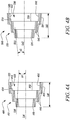
- FIGS. 2A and 2B illustrate a front view and a side view, respectively, of a device 200 for use with a vehicle-mounted image acquisition unit, such as the vehicle-mounted image acquisition unit 102 described with reference to FIG. 1 .
- FIG. 2C illustrates a sectional side view of the device 200.
- the device 200 is a stray light-reducing device for use with the vehicle-mounted image acquisition unit 102.
- the device 200 may reduce background and side incident light (hereinafter referred to as "stray light").
- the device 200 includes a main body 201 including a first end 210 and a second end 220 opposite to the first end 210.
- the main body 201 defines an interior cavity 230 extending between the first end 210 and the second end 220.
- the first end 210 of the main body 201 is configured to be disposed at or near the vehicle-mounted image acquisition unit 102 (shown in FIG. 3B ). In some examples, the first end 210 fits over the vehicle-mounted image acquisition unit 102.
- the vehicle-mounted image acquisition unit 102 has a field of view extending through the interior cavity 230 and through the second end 220 to an outside environment surrounding the vehicle 100 (shown in FIG. 3B ). In some examples, the main body 201 provides the vehicle-mounted image acquisition unit 102 with a wide field of view to the outside environment surrounding the vehicle 100.
- the main body 201 is substantially cone-shaped such that the main body 201 diverges from the first end 210 toward the second end 220.
- the main body 201 has a first width "W1" at the first end 210 and a second width "W2" at the second end 220.
- the first width "W1" is less than the second width "W2".
- a ratio between the first width "W1" and the second width "W2" is about 1 : 1.5, 1 : 2, 1 : 2.5, 1 : 3, 1 : 4, or 1 : 5.
- at least two opposing surfaces of the interior cavity 230 diverge relative to one another from the first end 210 of the main body 201 toward the second end 220 of the main body 201.
- the main body 201 defines a longitudinal axis "LA” along its length "LM".
- the length "LM” of the main body 201 may be increased to further reduce stray light travelling to the vehicle-mounted image acquisition unit 102.
- the main body 201 may be more susceptible to contaminants, such as dust, dirt, snow, water droplets, and other environmental debris.
- the length "LM” of the main body 201 may be from about 5 centimeters (cm) to about 20 cm. In some other examples, the length "LM” of the main body 201 may be more than about 20 cm.
- the length "LM" of the main body 201 is exemplary, and may be varied as per desired application attributes.
- the main body 201 has an annular cross-section. In other examples, the main body 201 may have an oval, a square, a rectangular, a triangular, or a polygonal cross-section. In some examples, the main body 201 may have an inner surface 202 and an outer surface 204. In some examples, the inner surface 202 of the main body 201 may be black-colored and/or have a matte surface finish for maximum light absorption. The inner surface 202 includes any geometry to reduce stray light travelling to the vehicle-mounted image acquisition unit 102. In some examples, the inner surface 202 may have a circular, an oval, a square, a rectangular, a triangular, or a polygonal cross-section.
- the outer surface 204 may include any geometry to match aerodynamic requirements of the vehicle 100.
- the outer surface 204 may have a circular, an oval, a square, a rectangular, a triangular, or a polygonal cross-section.
- the main body 201 includes a material including at least one of glass-filled nylon, nylon 66, polycarbonate (PC), acrylonitrile butadiene styrene (ABS) and polycarbonate-acrylonitrile butadiene styrene (PC-ABS).
- the main body 201 includes an elastic and/or a flexible material.
- the main body 201 further includes a plurality of stepped sections 250 disposed adjacent to each other.
- the stepped sections 250 are defined on the inner surface 202 of the main body 201.
- the outer surface 204 may also include similar stepped sections.
- the plurality of stepped sections 250 are spaced apart from each other along the longitudinal axis "LA" of the main body 201.
- the plurality of stepped sections 250 are disposed between the first end 210 and the second end 220.
- the plurality of stepped sections 250 on the inner surface 202 may reduce stray light travelling to the lens of the vehicle-mounted image acquisition unit 102.
- the device 200 includes two stepped sections 250. However, the number of stepped sections 250 may vary as per desired application attributes.
- Each stepped section 250 of the plurality of stepped sections 250 includes two edges 252 and 254. Further, the inner surface 202 of the main body 201 includes one additional edge 252 extending from the first end 210 and disposed adjacent to the one of the stepped sections 250.
- the edges 252, 254 may extend along a circumference of the inner surface 202 of the main body 201. Edge 252 may be substantially parallel along the longitudinal axis "LA" of the main body 201. Edge 254 may be substantially perpendicular to the longitudinal axis "LA” of the main body 201.
- the plurality of stepped sections 250 may be substantially L-shaped. In some examples, the edge 252 may be inclined relative to the longitudinal axis "LA" of the main body 201.
- an angle A1 between the edge 252 and the longitudinal axis "LA” of the main body 201 may be less than about 10 degrees. In some other examples, the angle A1 between the edge 252 and the longitudinal axis "LA” of the main body 201 may be from about 10 degrees to about 60 degrees. In some examples, an angle A2 between the edge 254 and the longitudinal axis "LA” of the main body 201 may be from about 30 degrees to about 90 degrees. In some other examples, the angle A2 between the edge 254 and the longitudinal axis "LA” of the main body 201 may be less than about 30 degrees. In some examples, an angle A3 between the edge 252 and the edge 254 may be from about 70 degrees to about 120 degrees. In some other examples, the angle A3 between the edge 252 and the edge 254 may be less than about 70 degrees. In some examples, the plurality of stepped sections 250 may be present only on the inner surface 202 of the main body 201.
- Each edge 252 has a length "LS". In some examples, the lengths "LS" of the edges 252 may be equal to one another. In some other examples, the lengths "LS" of the edges 252 may be different from each other.
- Each edge 254 has a height "HS”. In some examples, the heights "HS” of the edges 254 may be equal to one another. In some other examples, the heights "HS” of the edges 254 may be different from each other. In some examples, a ratio between the length "LS" and the height "HS” ratio may be 1:1, 1.5 : 1, 2 : 1, 3 : 1, or 4 : 1. The ratio selected may also be selected based on a field of view "FOV" (shown in FIG. 7 ) of the image acquisition unit 102.
- FOV field of view
- Stray light may be considerably reduced by optimizing the parameters, such as the length "LS” and the height "HS” of the edges 252, 254, respectively, and the angle A3 between the edges 252, 254.
- the main body 201 further defines a plurality of apertures 240 therethrough between the first end 210 and the second end 220.
- the plurality of apertures 240 are arranged in a plurality of circumferential rows 245 spaced apart from each other along the length "LM" of the main body 201.
- the circumferential rows 245 are spaced apart from each other along the longitudinal axis "LA" of the main body 201.
- the position of the plurality of apertures 240 may be chosen such that stray light from the outside environment surrounding the vehicle 100 does not enter the interior cavity 230 of the device 200 through the plurality of apertures 240.
- the plurality of apertures 240 are present in each of the edges 254 and extend substantially along the length "LM" of the main body 201. Specifically, a set of apertures 240 start from each edge 254 and extends through the main body 201. Further, another set of apertures 240 start from the second end 220 and extends through the main body 201. In some other examples, the plurality of apertures 240 are alternatively or additionally present in each of the edges 252, 254 and are inclined to the longitudinal axis "LA" of the main body 201. In some examples, two or more of the plurality of apertures 240 may be in fluid communication with each other.
- the main body 201 defines an aperture axis "HA" of each aperture 240. In the illustrated example, the aperture axis "HA" of each aperture 240 is substantially parallel to the longitudinal axis "LA" of the main body 201.
- each aperture 240 has a circular cross-section.
- a diameter of each aperture 240 may be from about 1 millimeter (mm) to about 10 mm. In some other examples, the diameter of each aperture 240 may be less than about 1 mm. In other examples, one or more of the apertures 240 may have an oval, a square, a rectangular, a triangular, or a polygonal cross-section.
- the plurality of apertures 240 may be drilled or molded in the main body 201.
- a density of the apertures 240 may be in a range of about 5 to 100 apertures per cm 2 .
- the diameter, the shape, and the density of the plurality of apertures 240 are exemplary, and may be varied as per desired application attributes.
- the diameter, shape, and density of the plurality of apertures 240 may be varied based on the type of the vehicle-mounted image acquisition unit 102 and the mount location of the vehicle-mounted image acquisition unit 102. Moreover, the diameter, shape, and density of the plurality of apertures 240 may be varied such that stray light from the outside environment surrounding the vehicle 100 does not enter the interior cavity 230 of the device 200 through the plurality of apertures 240.
- An airflow from the first end 210 or the second end 220 may be generated from the movement of the vehicle 100 (e.g., while driving).
- the airflow is generated that flows into the device 200.
- This airflow within the interior cavity 230 of the main body 201 is at least partially expelled through the plurality of apertures 240 and removes the contaminants, such as loose dirt or debris, that may have accumulated on the lens or in the interior cavity 230.
- the airflow blows the contaminants off the lens and the interior cavity 230 through the plurality of apertures 240 in the main body 201.
- the airflow may be artificially generated by a flow unit (shown in FIG. 8 ) to discharge the contaminants through the plurality of apertures 240.
- a water mister may also be included in cooperation with the airflow from the movement of the vehicle 100 and/or the flow unit.
- FIG. 3A illustrates an image acquisition system 300 for use with the vehicle 100.
- the image acquisition systemt 300 includes the image acquisition unit 102 and the device 200.
- the device 200 is secured to the vehicle-mounted image acquisition unit 102.
- the device 200 may be removably attached to the vehicle-mounted image acquisition unit 102.
- the first end 210 of the main body 201 is secured to the vehicle-mounted image acquisition unit 102 by at least one of adhesive, fasteners and a ring mount.
- the device 200 may be an integral component of the vehicle-mounted image acquisition unit 102.
- FIG. 3B illustrates the device 200 removed from the vehicle-mounted image acquisition unit 102.
- the device 200 may be removed from the vehicle-mounted image acquisition unit 102 for cleaning purposes.
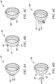
- FIGS. 4A and 4B illustrate sectional side views of other exemplary devices 400, 500, respectively.
- FIG. 4A illustrates the device 400 similar to the device 200 shown of FIGS. 2A, 2B and 2C , with each of features 401 to 454 corresponding to equivalent features 201 to 254 of the device 200.
- the main body 401 defines a longitudinal axis "LA1" along its length "LM1", and an aperture axis "HA1" of each aperture 440.
- the aperture axis "HA1" of each aperture 440 is inclined relative to the longitudinal axis "LA1" of the main body 401.
- the aperture axis "HA1" of each aperture 440 is inclined toward the second end 420.
- an angle A4 between the aperture axis "HA1" and the longitudinal axis “LA1” may be from about 10 degrees to about 60 degrees. In some other examples, the angle A4 between the aperture axis "HA1” and the longitudinal axis “LA1” may be less than about 10 degrees. The angle A4 between the aperture axis "HA1” and the longitudinal axis "LA1” may be chosen such that the angle A4 enhances the egress of the contaminants from the interior cavity 430 of the main body 401.
- FIG. 4B illustrates the device 500 similar to the device 200 shown of FIGS. 2A, 2B and 2C , with each of features 501 to 554 corresponding to equivalent features 201 to 254 of the device 200.
- the main body 501 defines a longitudinal axis "LA2" along its length "LM2", and an aperture axis "HA2" of each aperture 540.
- the aperture axis "HA2" of each aperture 540 is inclined relative to the longitudinal axis "LA2" of the main body 501.
- the aperture axis "HA2" of each aperture 540 is inclined toward the first end 510.
- an angle A5 between the aperture axis "HA2" and the longitudinal axis “LA2” may be from about 10 degrees to about 60 degrees. In some other examples, the angle A5 between the aperture axis "HA2" and the longitudinal axis “LA2” may be less than about 10 degrees. The angle A5 between the aperture axis "HA2" and the longitudinal axis "LA2” may be chosen such that the angle A5 enhances the egress of the contaminants from the interior cavity 530 of the main body 501.
- FIGS. 5A, 5B, 5C illustrate different shapes of each aperture 240 of the device 200 (shown in FIGS. 2A-2C ).
- FIG. 5A illustrates an aperture 240a that is cylindrical along its length.
- FIG. 5B illustrate an aperture 240b that is substantially cuboidal along its length.
- FIG. 5C illustrate an aperture 240c that is cone-shaped along its length. In this example, the aperture 240c may act like a nozzle to improve discharge of the contaminants.
- FIGS. 6A, 6B, 6C, 6D, and 6E illustrate different examples of securing the device 200 to the vehicle-mounted image acquisition unit 102 (shown in FIG. 1 ).
- FIG. 6A illustrates the device 200 with an attachment portion 615 including an adhesive layer 610.
- the adhesive layer 610 on the attachment portion 615 adhesively engages the first end 210 with the vehicle-mounted image acquisition unit 102 (shown in FIG. 1 ).
- the first end 210 of the device 200 may include the adhesive layer 610 for attachment with the vehicle-mounted image acquisition unit 102.
- FIG. 6B illustrates the device 200 with mounting tabs 620.
- the first end 210 of the device 200 may include the mounting tabs 620.
- the mounting tabs 620 includes one or more apertures 625 therethrough for mounting the device 200 at or to the vehicle-mounted image acquisition unit 102 via suitable fasteners (not shown), for example, screws, bolts, a nut and bolt assembly, or the like.
- FIG. 6C illustrates the device 200 with a threaded portion 630.
- the first end 210 of the device 200 may include the threaded portion 630.
- FIG. 6C illustrates the device 200 with an external threaded portion 630.
- the first end 210 may include an internal threaded portion (not shown).
- the external threaded portion 630 can be threadingly engaged with an internal threaded portion (not shown) of the vehicle-mounted image acquisition unit 102.
- the internal threaded portion may be formed on an inner surface of the first end 210 and can be threadingly engaged with an external threaded portion (not shown) of the vehicle-mounted image acquisition unit 102.
- FIG. 6D illustrates the device 200 with a bayonet type mounting mechanism 640.
- the first end 210 of the device 200 may include an attachment portion 641 with one or more radial pins 645.
- the attachment portion 641 includes two radial pins 645.
- the attachment portion 641 may include L-shaped slots (not shown).
- the radial pins 645 disposed on the attachment portion 641 can be locked with corresponding L-shaped slots 646 in the vehicle-mounted image acquisition unit 102.
- a L-shaped slot formed in the attachment portion 641 can be locked with a radial pin (not shown) in the vehicle-mounted image acquisition unit 102.
- FIG. 6E illustrates a mount ring 650.
- the first end 210 of the device 200 may include an attachment portion 651 secured to the vehicle-mounted image acquisition unit 102 using the mount ring 650.
- FIG. 7 illustrates the device 200 mounted to the vehicle-mounted image acquisition unit 102 (partially shown in FIG. 7 ).
- the vehicle-mounted image acquisition unit 102 has the "FOV" extending through the interior cavity 230 and through the second end 220 to an outside environment "OE" surrounding the vehicle 100 (shown in FIG. 1 ).
- the main body 201 provides the vehicle-mounted image acquisition unit 102 with a wide field of view to the outside environment "OE" surrounding the vehicle 100.
- the device 200 may substantially prevent stray light "SL” in the outside environment "OE” from interfering with the operation of the vehicle-mounted image acquisition unit 102.
- the plurality of stepped sections 250 defined on the inner surface 202 may reduce or eliminate stray light "SL” travelling to the lens of the vehicle-mounted image acquisition unit 102.
- the apertures 240 may be positioned such that stray light "SL” does not enter the interior cavity 230 of the device 200 through the apertures 240.
- the apertures 240 may substantially extend along the longitudinal axis "LA” of the device 200 such that stray light "SL” cannot enter into the interior cavity 230 through the apertures 240.
- An airflow "AF” flows into the device 200.
- the airflow “AF” flows from the first end 210.
- the airflow “AF” may alternatively or additionally flow from the second end 220.
- the airflow “AF” may be generated due to the movement of the vehicle 100 or by a flow unit (not shown).
- the airflow “AF” enters the interior cavity 230 of the main body 201 and is at least partially expelled through the apertures 240.
- the airflow “AF” may remove various contaminants, such as loose dirt or debris, that may have accumulated on the vehicle-mounted image acquisition unit 102 or in the interior cavity 230.
- the airflow "AF” may entrain the contaminants and flow the contaminants through the apertures 240 in the main body 201.
- the device 200 may therefore provide self-cleaning and stray-light reducing functionality upon attachment with the vehicle-mounted image acquisition unit 102.
- FIG. 8 illustrates the device 200 including a flow unit 800 configured to generate flow of a fluid within the interior cavity 230 (shown in FIG. 2C ) such that the fluid is discharged through the plurality of apertures 240 (shown in FIG. 2C ) to remove the contaminants in the device 200.
- the flow unit 800 may be mounted next to the vehicle-mounted image acquisition unit 102 (shown in FIG. 1 ). In some other examples, the flow unit 800 may be mounted anywhere in the vehicle 100.
- the flow unit 800 may include one or more hoses 820 or conduits to route the fluid to the desired location in the interior cavity 230.
- the flow unit 800 may include one or more of a fluid tank, a fluid compressor, and a pump.
- the fluid compressor may include a vehicle air compressor already in use in the vehicle 100, such as for supplying pressurized air for a suspension system, or for engine charging, brake actuating, lock actuating and/or the like.
- the flow unit 800 may further include any a nozzle, a blower, a dirt detector or a combination thereof.
- the hoses 820 may be routed directly to the interior cavity 230 of the device 200.
- the fluid is fed to the interior cavity 230 of the device 200 from a valve 850.
- nozzles 830a, 830b may be configured to spray the interior cavity 230 of the device 200 with the fluid.
- the nozzles 830a, 830b may be attached to an end of the one or more hoses 820.
- the fluid is compressed air, a cleaning fluid, aerosolized fluid, or a combination thereof.
- the compressed air may include any gas, such as engine or compressor exhaust, nitrogen, and the like, suitable for blowing through the device 200 to remove contaminants.
- the fluid is fed to the nozzle 830a from a valve 840.
- the nozzles 830a, 830b are configured to blow air across the device 200 to blow off the contaminants, such as loose dirt or debris through the plurality of apertures 240.
- a controller 810 is communicatively coupled to the flow unit 800. In some examples, the controller 810 regulates the flow unit 800 to direct the fluid to the interior cavity 230. Further, the controller 810 may receive output signals from the dirt detector (not shown). In some examples, the controller 810 is configured to detect the contaminants in the interior cavity 230 based on the detection by the dirt detector. The dirt detector may detect the contaminants and generate electrical signals based on the detection.
- the controller 810 may provide an output to a user interface (not shown).
- the user interface may include the display device.
- the user interface may include an audio device, a haptic device, one or more input devices (e.g., keyboard, touchscreen, keypad etc.), or combinations thereof.
- the controller 810 may generate an alert or notification upon detecting the contaminants in the interior cavity 230. The alert or notification may be sent to the user interface. The alert or notification may be visual, audible, haptic, or combinations thereof.
- the controller 810 may automatically activate the flow unit 800 upon detecting the contaminants in the interior cavity 230. In some other examples, the controller 810 is programmed to activate the flow unit 800 to supply the fluid at a scheduled time after the start-up of the vehicle 100. In some examples, the controller 810 may periodically activate the flow unit 800. In some examples, the controller 810 may analyze images captured by the vehicle-mounted image acquisition unit 102 and activate the flow unit 800 based on the image quality of the captured images. In some examples, the flow unit 800 generates a constant flow of the fluid at all times during the operation of the vehicle-mounted image acquisition unit 102. In some other examples, the flow of the fluid may be in a pulsed manner. In order to create the pulsed flow of the fluid, the controller 810 can transmit a pulse width modulated control signal to operate the flow unit 800.
- the controller 810 may include a processor (not shown) and a memory (not shown).
- the memory may include computer executable instructions that are executable by the processor to perform a logic associated with the controller 810.
- the controller 810 may include analog-to-digital converters to process the signals from the various components of the flow unit 800.
- the processor and the memory may be in communication with each other.
- the processor may be in communication with additional components.
- the processor may be in communication with the user interface that may indicate to the driver the presence of the contaminants in the interior cavity 230 of the device 200.
- the processor may also receive inputs from the driver via the user interface to activate the flow unit 800.
- the controller 810 may control various parameters of the flow unit 800 based on the inputs received from the driver.
- the processor may be any device that performs logic operations.
- the processor may include a general processor, a central processing unit, an application specific integrated circuit (ASIC), a digital signal processor, a field programmable gate array (FPGA), a digital circuit, an analog circuit, a controller, a microcontroller, any other type of processor, or any combination thereof.
- the processor may include one or more components operable to execute computer executable instructions or computer code embodied in the memory.
- each module may include an application specific integrated circuit (ASIC), a Field Programmable Gate Array (FPGA), a circuit, a digital logic circuit, an analog circuit, a combination of discrete circuits, gates, or any other type of hardware or combination thereof.
- ASIC application specific integrated circuit
- FPGA Field Programmable Gate Array
- each module may include memory hardware, such as a portion of the memory, for example, that includes instructions executable with the processor or other processor to implement one or more of the features of the module.
- the module may or may not include the processor.
- each module may just be the portion of the memory or other physical memory that includes instructions executable with the processor or other processor to implement the logic of the corresponding module without the module including any other hardware.
- controller 810 may be stored in a computer readable storage medium (for example, as logic implemented as computer executable instructions or as data structures in memory). All or part of the controller 810 and its logic and data structures may be stored on, distributed across, or read from one or more types of computer readable storage media. Examples of the computer readable storage medium may include a hard disk, a floppy disk, a CD-ROM, a flash drive, a cache, volatile memory, non-volatile memory, RAM, flash memory, or any other type of computer readable storage medium or storage media.
- the computer readable storage medium may include any type of non-transitory computer readable medium, such as a CD-ROM, a volatile memory, a non-volatile memory, ROM, RAM, or any other suitable storage device.
- the processing capability of the controller 810 may be distributed among multiple entities, such as among multiple processors and memories, optionally including multiple distributed processing systems. Additionally, peripheral interfaces (not shown) may be provided.
- the peripheral interfaces may include analog interfaces (e.g., LVDS serial interface), digital interfaces, such as I2C, SPI, CAN, LIN, or similar digital high speed transmission interface, or Ethernet to connect the controller 810 to other devices, for example, the display device.
- analog interfaces e.g., LVDS serial interface
- digital interfaces such as I2C, SPI, CAN, LIN, or similar digital high speed transmission interface, or Ethernet to connect the controller 810 to other devices, for example, the display device.
- FIG. 9 illustrates a device 900 substantially similar to the device 200 shown of FIGS. 2A, 2B and 2C .
- a main body 901 defines a longitudinal axis "LA3" along its length "LM3".
- a plurality of stepped sections 950 are only present on an inner surface 902 of the main body 901.
- An outer surface 904 of the main body 901 is smooth and does not include stepped sections.
- the outer surface 904 of the main body 901 is cone-shaped along its length "LM3" and diverges from a first end 910 toward a second end 920.
- the outer surface 904 may include any geometry to match aerodynamic requirements of the vehicle 100 (shown in FIG. 1 ).
- the outer surface 904 may have a circular, an oval, a square, a rectangular, a triangular, or a polygonal cross-section.
- the inner surface 902 includes the plurality of stepped sections 950 irrespective of a geometry of the outer surface 904.
- the outer surface 904 may include some hooks, eyes or similar fastening means for fixation purposes.
- Each stepped section 950 of the plurality of stepped sections 950 includes two edges 952 and 954. Further, the inner surface 902 of the main body 901 includes one additional edge 952 extending from the first end 910 and disposed adjacent to one of the plurality of stepped sections 950.
- the main body 901 further defines a plurality of apertures 940 therethrough between the first end 910 and the second end 920.
- the plurality of apertures 940 are arranged in a plurality of circumferential rows spaced apart from each other along the length "LM3" of the main body 901.
Abstract
Description
- The present invention relates generally to a device for an image acquisition unit, and more specifically to a device for use with a vehicle-mounted image acquisition unit. The invention also refers to an image acquisition system for use with a vehicle with such a device and a vehicle with such an image acquisition system and/or such a device.
- Vehicles may include one or more image acquisition units. An image captured by the image acquisition unit may include additional information for alerting or informing a driver. Stray light emitted from a region other than a region of interest often sets a working limit on a dynamic range of an imaging system and limits signal-to-noise ratio or contrast ratio. Further, lens of such image acquisition units may easily catch contaminants, such as, dust, dirt, snow, water droplets, and other environmental debris. This may adversely impact normal operation of the image acquisition units.
- It is the object of the present invention to overcome the drawbacks of the prior art.
- The object of the present invention is achieved by a device for use with a vehicle-mounted image acquisition unit according to
claim 1. Preferred embodiments of such a device are described in claims 2 to 10. The object is also achieved by an image acquisition system for use with a vehicle with such a device in line with claim 11, with a preferred embodiment being described in claim 12. Further, the object is achieved by a vehicle with such a device and/or such an image acquisition system. - In one aspect, there is provided a device for use with a vehicle-mounted image acquisition unit. The device includes a main body. The main body includes a first end and a second end opposite to the first end. The main body further defines an interior cavity extending between the first end and the second end, and a plurality of apertures therethrough between the first end and the second end. The first end of the main body is configured to be disposed at or near the vehicle-mounted image acquisition unit. The vehicle-mounted image acquisition unit has a field of view extending through the interior cavity and through the second end to an outside environment surrounding a vehicle.
- In an example, the main body may be substantially cone-shaped such that the main body diverges from the first end toward the second end.
- In an example, the plurality of apertures may be arranged in a plurality of circumferential rows spaced apart from each other along a length of the main body.
- In an example, the main body may further include a plurality of stepped sections disposed adjacent to each other.
In an example, the plurality of stepped sections may be defined on an inner surface of the main body. - In an example, the main body may further define a longitudinal axis along its length. An aperture axis of each aperture may be inclined relative to the longitudinal axis of the main body. In an example, at least one aperture from the plurality of apertures may be cone-shaped along its length.
- In an example, each aperture may have a circular cross-section.
- In an example, the first end of the main body may be secured to the vehicle-mounted image acquisition unit by at least one of adhesive, fasteners and a ring mount.
- In an example, the device may further include a flow unit configured to generate flow of a fluid within the interior cavity such that the fluid may be discharged through the plurality of apertures.
- In an example, the main body may include a material including at least one of glass-filled nylon, nylon 66, polycarbonate (PC), acrylonitrile butadiene styrene (ABS) and polycarbonate-acrylonitrile butadiene styrene (PC-ABS).
- In another aspect, there is provided an image acquisition system for use with a vehicle. The image acquisition system includes an image acquisition unit mounted on the vehicle and a device including a main body. The main body includes a first end and a second end opposite to the first end. The main body further defines an interior cavity extending between the first end and the second end, and a plurality of apertures therethrough between the first end and the second end. The first end of the main body is configured to be disposed at or near the image acquisition unit. The image acquisition unit has a field of view extending through the interior cavity and through the second end to an outside environment surrounding the vehicle.
- In an example, the image acquisition unit may include at least one of cameras, sensors, image sensors, optical sensors, laser sensors and scanners.
- In an example, the main body may be substantially cone-shaped such that the main body diverges from the first end toward the second end.
- In an example, the plurality of apertures may be arranged in a plurality of circumferential rows spaced apart from each other along a length of the main body.
- In an example, the main body may further include a plurality of stepped sections disposed adjacent to each other.
- In an example, the main body may further define a longitudinal axis along its length. An aperture axis of each aperture may be inclined relative to the longitudinal axis of the main body.
- In an example, at least one aperture from the plurality of apertures may be cone-shaped along its length.
- In an example, the first end of the main body may be secured to the image acquisition unit by at least one of adhesive, fasteners and a ring mount.
- In one aspect, there is provided a device for use with a vehicle-mounted image acquisition unit. The device includes a main body. The main body includes a first end, a second end opposite to the first end, and a plurality of stepped sections disposed between the first end and the second end. The main body further defines an interior cavity extending between the first end and the second end, and a plurality of apertures therethrough between the first end and the second end. The first end of the main body is configured to be secured to the vehicle-mounted image acquisition unit. The vehicle-mounted image acquisition unit has a field of view extending through the interior cavity and through the second end to an outside environment surrounding a vehicle.
- The foregoing summary, as well as the following detailed description, will be better understood when read in conjunction with the appended drawings. For the purpose of illustration, certain examples of the present description are shown in the drawings. It should be understood, however, that the disclosure is not limited to the precise arrangements and instrumentalities shown. The accompanying drawings, which are incorporated in and constitute a part of this specification, illustrate an implementation of system, apparatuses, and methods consistent with the present description and, together with the description, serve to explain advantages and principles consistent with the disclosure. The figures are not necessarily drawn to scale. Like numbers used in the figures refer to like components. However, it will be understood that the use of a number to refer to a component in a given figure is not intended to limit the component in another figure labeled with the same number.
- FIG. 1
- illustrates a schematic side view of an example of a vehicle having a vehicle-mounted image acquisition unit;
- FIGS. 2A and 2B
- illustrate a front view and a perspective view, respectively, of an example of a device associated with the vehicle-mounted image acquisition unit;
- FIG. 2C
- illustrates a sectional side view of the device of
FIGS. 2A and 2B ; - FIG. 3A
- illustrates the device secured to the vehicle-mounted image acquisition unit;
- FIG. 3B
- illustrates the device removed from the vehicle-mounted image acquisition unit;
- FIGS. 4A and 4B
- illustrate sectional side views of different examples of the device;
- FIGS. 5A, 5B and 5C
- illustrate different examples of apertures of the device;
- FIGS. 6A, 6B, 6C, 6D and 6E
- illustrate different examples of securing the device to the vehicle-mounted image acquisition unit;
- FIG. 7
- illustrates an exemplary operation of the device when secured to the vehicle-mounted image acquisition unit;
- FIG. 8
- illustrates an example of the device with a flow unit; and
- FIG. 9
- illustrates a sectional side view of another example of the device.
- The following detailed description is provided to assist the reader in gaining a comprehensive understanding of the methods, apparatuses, and/or systems described herein. Accordingly, various changes, modifications, and equivalents of the systems, apparatuses and/or methods described herein will be suggested to those of ordinary skill in the art. Also, descriptions of well-known functions and constructions may be omitted for increased clarity and conciseness.
- It is to be understood that the phraseology and terminology employed herein are for the purpose of description and should not be regarded as limiting. For example, the use of a singular term, such as, "a" is not intended as limiting of the number of items. Further, it should be understood that any one of the features can be used separately or in combination with other features. Other systems, methods, features, and advantages of the disclosure will be or become apparent to one with skill in the art upon examination of the detailed description. It is intended that all such additional systems, methods, features, and advantages be included within this description, be within the scope of the present disclosure, and be protected by the accompanying claims.
- Referring now to the Figures,
FIG. 1 illustrates an example of avehicle 100. Animage acquisition unit 102 is mounted on thevehicle 100. Theimage acquisition unit 102 may be interchangeably referred to as a vehicle-mountedimage acquisition unit 102. The vehicle-mountedimage acquisition unit 102 may be provided at any location on thevehicle 100, for example, a rear of thevehicle 100, a side of thevehicle 100, a front of thevehicle 100, and so forth. The vehicle-mountedimage acquisition unit 102 may provide images based on the requirements of a driver or an occupant of thevehicle 100. The images provided by the vehicle-mountedacquisition unit 102 may also be used in any ADAS, machine vision, automated driving or other function as required by vehicle systems. In an example, the vehicle-mountedimage acquisition unit 102 may help the driver to view areas rear of thevehicle 100. In another example, the vehicle-mountedimage acquisition unit 102 may help the driver to view areas to the side of thevehicle 100. In some examples, the vehicle-mountedimage acquisition unit 102 may process image data to detect objects, such as objects to the rear of thevehicle 100 during a reversing maneuver. In some examples, the vehicle-mountedimage acquisition unit 102 may be used to detect vehicles, such as approaching or following vehicles, or vehicles at a side lane adjacent to thevehicle 100. The vehicle-mountedimage acquisition unit 102 may also enable the driver to view areas in a blindspot. The vehicle-mountedimage acquisition unit 102 may be fixedly or adjustably mounted on thevehicle 100. The vehicle-mountedimage acquisition unit 102 may be configured to acquire both still images and moving images (e.g., video). Further, the vehicle-mountedimage acquisition unit 102 may include at least one of cameras, sensors, image sensors, optical sensors, laser sensors and scanners. The vehicle-mountedimage acquisition unit 102 may further include a lens (not shown). - Though one vehicle-mounted
image acquisition unit 102 is shown inFIG. 1 , multiple vehicle-mounted image acquisition units may be disposed at different locations on thevehicle 100. The vehicle-mountedimage acquisition unit 102 may process and provide images at a display device (not shown) for viewing by the driver of thevehicle 100. The display device may include any type of device including a display, for example, but not limited to, a display in an instrument panel of thevehicle 100, a head-up display (HUD), a smartphone, a tablet computer, a rearview or a sideview mirror including a display, and so forth. The display device may be fixedly or adjustably mounted inside or outside thevehicle 100. In some cases, the display device may simultaneously or selectively display multiple images from multiple vehicle-mountedimage acquisition units 102. - Although the
vehicle 100 is illustrated as a passenger car inFIG. 1 , the vehicle-mountedimage acquisition unit 102 may be used with other types of vehicles, for example, buses, trucks, off-road vehicles, motorcycles, aircrafts, bicycles, trams, locomotives, heavy-duty vehicles used in construction and earthworking, and so forth. -
FIGS. 2A and 2B illustrate a front view and a side view, respectively, of adevice 200 for use with a vehicle-mounted image acquisition unit, such as the vehicle-mountedimage acquisition unit 102 described with reference toFIG. 1 .FIG. 2C illustrates a sectional side view of thedevice 200. Thedevice 200 is a stray light-reducing device for use with the vehicle-mountedimage acquisition unit 102. Thedevice 200 may reduce background and side incident light (hereinafter referred to as "stray light"). Referring toFIGS. 2A, 2B and2C , thedevice 200 includes amain body 201 including afirst end 210 and asecond end 220 opposite to thefirst end 210. Themain body 201 defines aninterior cavity 230 extending between thefirst end 210 and thesecond end 220. Thefirst end 210 of themain body 201 is configured to be disposed at or near the vehicle-mounted image acquisition unit 102 (shown inFIG. 3B ). In some examples, thefirst end 210 fits over the vehicle-mountedimage acquisition unit 102. The vehicle-mountedimage acquisition unit 102 has a field of view extending through theinterior cavity 230 and through thesecond end 220 to an outside environment surrounding the vehicle 100 (shown inFIG. 3B ). In some examples, themain body 201 provides the vehicle-mountedimage acquisition unit 102 with a wide field of view to the outside environment surrounding thevehicle 100. - In some examples, the
main body 201 is substantially cone-shaped such that themain body 201 diverges from thefirst end 210 toward thesecond end 220. Themain body 201 has a first width "W1" at thefirst end 210 and a second width "W2" at thesecond end 220. The first width "W1" is less than the second width "W2". In some examples, a ratio between the first width "W1" and the second width "W2" is about 1 : 1.5, 1 : 2, 1 : 2.5, 1 : 3, 1 : 4, or 1 : 5. In some examples, at least two opposing surfaces of theinterior cavity 230 diverge relative to one another from thefirst end 210 of themain body 201 toward thesecond end 220 of themain body 201. Themain body 201 defines a longitudinal axis "LA" along its length "LM". In some examples, the length "LM" of themain body 201 may be increased to further reduce stray light travelling to the vehicle-mountedimage acquisition unit 102. However, by increasing the length "LM" of themain body 201, themain body 201 may be more susceptible to contaminants, such as dust, dirt, snow, water droplets, and other environmental debris. In some examples, the length "LM" of themain body 201 may be from about 5 centimeters (cm) to about 20 cm. In some other examples, the length "LM" of themain body 201 may be more than about 20 cm. The length "LM" of themain body 201 is exemplary, and may be varied as per desired application attributes. - In an example, the
main body 201 has an annular cross-section. In other examples, themain body 201 may have an oval, a square, a rectangular, a triangular, or a polygonal cross-section. In some examples, themain body 201 may have aninner surface 202 and anouter surface 204. In some examples, theinner surface 202 of themain body 201 may be black-colored and/or have a matte surface finish for maximum light absorption. Theinner surface 202 includes any geometry to reduce stray light travelling to the vehicle-mountedimage acquisition unit 102. In some examples, theinner surface 202 may have a circular, an oval, a square, a rectangular, a triangular, or a polygonal cross-section. In some examples, theouter surface 204 may include any geometry to match aerodynamic requirements of thevehicle 100. In some examples, theouter surface 204 may have a circular, an oval, a square, a rectangular, a triangular, or a polygonal cross-section. - In some examples, the
main body 201 includes a material including at least one of glass-filled nylon, nylon 66, polycarbonate (PC), acrylonitrile butadiene styrene (ABS) and polycarbonate-acrylonitrile butadiene styrene (PC-ABS). In some examples, themain body 201 includes an elastic and/or a flexible material. - In some examples, the
main body 201 further includes a plurality of steppedsections 250 disposed adjacent to each other. The steppedsections 250 are defined on theinner surface 202 of themain body 201. Theouter surface 204 may also include similar stepped sections. The plurality of steppedsections 250 are spaced apart from each other along the longitudinal axis "LA" of themain body 201. The plurality of steppedsections 250 are disposed between thefirst end 210 and thesecond end 220. The plurality of steppedsections 250 on theinner surface 202 may reduce stray light travelling to the lens of the vehicle-mountedimage acquisition unit 102. In the illustrated examples, thedevice 200 includes two steppedsections 250. However, the number of steppedsections 250 may vary as per desired application attributes. - Each stepped
section 250 of the plurality of steppedsections 250 includes twoedges inner surface 202 of themain body 201 includes oneadditional edge 252 extending from thefirst end 210 and disposed adjacent to the one of the steppedsections 250. Theedges inner surface 202 of themain body 201.Edge 252 may be substantially parallel along the longitudinal axis "LA" of themain body 201.Edge 254 may be substantially perpendicular to the longitudinal axis "LA" of themain body 201. In some examples, the plurality of steppedsections 250 may be substantially L-shaped. In some examples, theedge 252 may be inclined relative to the longitudinal axis "LA" of themain body 201. In some examples, an angle A1 between theedge 252 and the longitudinal axis "LA" of themain body 201 may be less than about 10 degrees. In some other examples, the angle A1 between theedge 252 and the longitudinal axis "LA" of themain body 201 may be from about 10 degrees to about 60 degrees. In some examples, an angle A2 between theedge 254 and the longitudinal axis "LA" of themain body 201 may be from about 30 degrees to about 90 degrees. In some other examples, the angle A2 between theedge 254 and the longitudinal axis "LA" of themain body 201 may be less than about 30 degrees. In some examples, an angle A3 between theedge 252 and theedge 254 may be from about 70 degrees to about 120 degrees. In some other examples, the angle A3 between theedge 252 and theedge 254 may be less than about 70 degrees. In some examples, the plurality of steppedsections 250 may be present only on theinner surface 202 of themain body 201. - Each
edge 252 has a length "LS". In some examples, the lengths "LS" of theedges 252 may be equal to one another. In some other examples, the lengths "LS" of theedges 252 may be different from each other. Eachedge 254 has a height "HS". In some examples, the heights "HS" of theedges 254 may be equal to one another. In some other examples, the heights "HS" of theedges 254 may be different from each other. In some examples, a ratio between the length "LS" and the height "HS" ratio may be 1:1, 1.5 : 1, 2 : 1, 3 : 1, or 4 : 1. The ratio selected may also be selected based on a field of view "FOV" (shown inFIG. 7 ) of theimage acquisition unit 102. - Stray light may be considerably reduced by optimizing the parameters, such as the length "LS" and the height "HS" of the
edges edges - In order to remove any contaminants from the
interior cavity 230 of thedevice 200, themain body 201 further defines a plurality ofapertures 240 therethrough between thefirst end 210 and thesecond end 220. In some examples, the plurality ofapertures 240 are arranged in a plurality ofcircumferential rows 245 spaced apart from each other along the length "LM" of themain body 201. In other words, thecircumferential rows 245 are spaced apart from each other along the longitudinal axis "LA" of themain body 201. The position of the plurality ofapertures 240 may be chosen such that stray light from the outside environment surrounding thevehicle 100 does not enter theinterior cavity 230 of thedevice 200 through the plurality ofapertures 240. In the illustrated example, the plurality ofapertures 240 are present in each of theedges 254 and extend substantially along the length "LM" of themain body 201. Specifically, a set ofapertures 240 start from eachedge 254 and extends through themain body 201. Further, another set ofapertures 240 start from thesecond end 220 and extends through themain body 201. In some other examples, the plurality ofapertures 240 are alternatively or additionally present in each of theedges main body 201. In some examples, two or more of the plurality ofapertures 240 may be in fluid communication with each other. Themain body 201 defines an aperture axis "HA" of eachaperture 240. In the illustrated example, the aperture axis "HA" of eachaperture 240 is substantially parallel to the longitudinal axis "LA" of themain body 201. - In some examples, each
aperture 240 has a circular cross-section. In some examples, a diameter of eachaperture 240 may be from about 1 millimeter (mm) to about 10 mm. In some other examples, the diameter of eachaperture 240 may be less than about 1 mm. In other examples, one or more of theapertures 240 may have an oval, a square, a rectangular, a triangular, or a polygonal cross-section. The plurality ofapertures 240 may be drilled or molded in themain body 201. A density of theapertures 240 may be in a range of about 5 to 100 apertures per cm2. The diameter, the shape, and the density of the plurality ofapertures 240 are exemplary, and may be varied as per desired application attributes. For example, the diameter, shape, and density of the plurality ofapertures 240 may be varied based on the type of the vehicle-mountedimage acquisition unit 102 and the mount location of the vehicle-mountedimage acquisition unit 102. Moreover, the diameter, shape, and density of the plurality ofapertures 240 may be varied such that stray light from the outside environment surrounding thevehicle 100 does not enter theinterior cavity 230 of thedevice 200 through the plurality ofapertures 240. - An airflow from the
first end 210 or thesecond end 220 may be generated from the movement of the vehicle 100 (e.g., while driving). In operation, as thevehicle 100 moves forward or backward, the airflow is generated that flows into thedevice 200. This airflow within theinterior cavity 230 of themain body 201 is at least partially expelled through the plurality ofapertures 240 and removes the contaminants, such as loose dirt or debris, that may have accumulated on the lens or in theinterior cavity 230. In other words, the airflow blows the contaminants off the lens and theinterior cavity 230 through the plurality ofapertures 240 in themain body 201. In some examples, the airflow may be artificially generated by a flow unit (shown inFIG. 8 ) to discharge the contaminants through the plurality ofapertures 240. In some examples, a water mister may also be included in cooperation with the airflow from the movement of thevehicle 100 and/or the flow unit. -
FIG. 3A illustrates animage acquisition system 300 for use with thevehicle 100. Theimage acquisition systemt 300 includes theimage acquisition unit 102 and thedevice 200. In the illustrated example, thedevice 200 is secured to the vehicle-mountedimage acquisition unit 102. In some examples, thedevice 200 may be removably attached to the vehicle-mountedimage acquisition unit 102. Thefirst end 210 of themain body 201 is secured to the vehicle-mountedimage acquisition unit 102 by at least one of adhesive, fasteners and a ring mount. In some other examples, thedevice 200 may be an integral component of the vehicle-mountedimage acquisition unit 102. -
FIG. 3B illustrates thedevice 200 removed from the vehicle-mountedimage acquisition unit 102. In some examples, thedevice 200 may be removed from the vehicle-mountedimage acquisition unit 102 for cleaning purposes. -
FIGS. 4A and 4B illustrate sectional side views of otherexemplary devices FIG. 4A illustrates thedevice 400 similar to thedevice 200 shown ofFIGS. 2A, 2B and2C , with each offeatures 401 to 454 corresponding toequivalent features 201 to 254 of thedevice 200. Themain body 401 defines a longitudinal axis "LA1" along its length "LM1", and an aperture axis "HA1" of eachaperture 440. In some examples, the aperture axis "HA1" of eachaperture 440 is inclined relative to the longitudinal axis "LA1" of themain body 401. In the illustrated example, the aperture axis "HA1" of eachaperture 440 is inclined toward thesecond end 420. In some examples, an angle A4 between the aperture axis "HA1" and the longitudinal axis "LA1" may be from about 10 degrees to about 60 degrees. In some other examples, the angle A4 between the aperture axis "HA1" and the longitudinal axis "LA1" may be less than about 10 degrees. The angle A4 between the aperture axis "HA1" and the longitudinal axis "LA1" may be chosen such that the angle A4 enhances the egress of the contaminants from theinterior cavity 430 of themain body 401. -
FIG. 4B illustrates thedevice 500 similar to thedevice 200 shown ofFIGS. 2A, 2B and2C , with each offeatures 501 to 554 corresponding toequivalent features 201 to 254 of thedevice 200. Themain body 501 defines a longitudinal axis "LA2" along its length "LM2", and an aperture axis "HA2" of eachaperture 540. In some examples, the aperture axis "HA2" of eachaperture 540 is inclined relative to the longitudinal axis "LA2" of themain body 501. In the illustrated example, the aperture axis "HA2" of eachaperture 540 is inclined toward thefirst end 510. In some examples, an angle A5 between the aperture axis "HA2" and the longitudinal axis "LA2" may be from about 10 degrees to about 60 degrees. In some other examples, the angle A5 between the aperture axis "HA2" and the longitudinal axis "LA2" may be less than about 10 degrees. The angle A5 between the aperture axis "HA2" and the longitudinal axis "LA2" may be chosen such that the angle A5 enhances the egress of the contaminants from theinterior cavity 530 of themain body 501. -
FIGS. 5A, 5B, 5C illustrate different shapes of eachaperture 240 of the device 200 (shown inFIGS. 2A-2C ).FIG. 5A illustrates anaperture 240a that is cylindrical along its length.FIG. 5B illustrate anaperture 240b that is substantially cuboidal along its length.FIG. 5C illustrate anaperture 240c that is cone-shaped along its length. In this example, theaperture 240c may act like a nozzle to improve discharge of the contaminants. -
FIGS. 6A, 6B, 6C, 6D, and 6E illustrate different examples of securing thedevice 200 to the vehicle-mounted image acquisition unit 102 (shown inFIG. 1 ). -
FIG. 6A illustrates thedevice 200 with anattachment portion 615 including anadhesive layer 610. Theadhesive layer 610 on theattachment portion 615 adhesively engages thefirst end 210 with the vehicle-mounted image acquisition unit 102 (shown inFIG. 1 ). In some other examples, thefirst end 210 of thedevice 200 may include theadhesive layer 610 for attachment with the vehicle-mountedimage acquisition unit 102. -
FIG. 6B illustrates thedevice 200 with mountingtabs 620. Thefirst end 210 of thedevice 200 may include the mountingtabs 620. The mountingtabs 620 includes one ormore apertures 625 therethrough for mounting thedevice 200 at or to the vehicle-mountedimage acquisition unit 102 via suitable fasteners (not shown), for example, screws, bolts, a nut and bolt assembly, or the like. -
FIG. 6C illustrates thedevice 200 with a threadedportion 630. In some other examples, thefirst end 210 of thedevice 200 may include the threadedportion 630.FIG. 6C illustrates thedevice 200 with an external threadedportion 630. However, in some other examples, thefirst end 210 may include an internal threaded portion (not shown). The external threadedportion 630 can be threadingly engaged with an internal threaded portion (not shown) of the vehicle-mountedimage acquisition unit 102. In some examples, the internal threaded portion may be formed on an inner surface of thefirst end 210 and can be threadingly engaged with an external threaded portion (not shown) of the vehicle-mountedimage acquisition unit 102. -
FIG. 6D illustrates thedevice 200 with a bayonettype mounting mechanism 640. Thefirst end 210 of thedevice 200 may include anattachment portion 641 with one or more radial pins 645. In some examples, theattachment portion 641 includes tworadial pins 645. However, in some other examples, theattachment portion 641 may include L-shaped slots (not shown). The radial pins 645 disposed on theattachment portion 641 can be locked with corresponding L-shapedslots 646 in the vehicle-mountedimage acquisition unit 102. In some other examples, a L-shaped slot formed in theattachment portion 641 can be locked with a radial pin (not shown) in the vehicle-mountedimage acquisition unit 102. -
FIG. 6E illustrates amount ring 650. Thefirst end 210 of thedevice 200 may include anattachment portion 651 secured to the vehicle-mountedimage acquisition unit 102 using themount ring 650. -
FIG. 7 illustrates thedevice 200 mounted to the vehicle-mounted image acquisition unit 102 (partially shown inFIG. 7 ). The vehicle-mountedimage acquisition unit 102 has the "FOV" extending through theinterior cavity 230 and through thesecond end 220 to an outside environment "OE" surrounding the vehicle 100 (shown inFIG. 1 ). In some examples, themain body 201 provides the vehicle-mountedimage acquisition unit 102 with a wide field of view to the outside environment "OE" surrounding thevehicle 100. - In some examples, the
device 200 may substantially prevent stray light "SL" in the outside environment "OE" from interfering with the operation of the vehicle-mountedimage acquisition unit 102. The plurality of steppedsections 250 defined on theinner surface 202 may reduce or eliminate stray light "SL" travelling to the lens of the vehicle-mountedimage acquisition unit 102. Theapertures 240 may be positioned such that stray light "SL" does not enter theinterior cavity 230 of thedevice 200 through theapertures 240. In some examples, theapertures 240 may substantially extend along the longitudinal axis "LA" of thedevice 200 such that stray light "SL" cannot enter into theinterior cavity 230 through theapertures 240. - An airflow "AF" flows into the
device 200. In the illustrated example, the airflow "AF" flows from thefirst end 210. However, the airflow "AF" may alternatively or additionally flow from thesecond end 220. The airflow "AF" may be generated due to the movement of thevehicle 100 or by a flow unit (not shown). The airflow "AF" enters theinterior cavity 230 of themain body 201 and is at least partially expelled through theapertures 240. The airflow "AF" may remove various contaminants, such as loose dirt or debris, that may have accumulated on the vehicle-mountedimage acquisition unit 102 or in theinterior cavity 230. The airflow "AF" may entrain the contaminants and flow the contaminants through theapertures 240 in themain body 201. Thedevice 200 may therefore provide self-cleaning and stray-light reducing functionality upon attachment with the vehicle-mountedimage acquisition unit 102. -
FIG. 8 illustrates thedevice 200 including aflow unit 800 configured to generate flow of a fluid within the interior cavity 230 (shown inFIG. 2C ) such that the fluid is discharged through the plurality of apertures 240 (shown inFIG. 2C ) to remove the contaminants in thedevice 200. In some examples, theflow unit 800 may be mounted next to the vehicle-mounted image acquisition unit 102 (shown inFIG. 1 ). In some other examples, theflow unit 800 may be mounted anywhere in thevehicle 100. Theflow unit 800 may include one ormore hoses 820 or conduits to route the fluid to the desired location in theinterior cavity 230. Theflow unit 800 may include one or more of a fluid tank, a fluid compressor, and a pump. In some examples, the fluid compressor may include a vehicle air compressor already in use in thevehicle 100, such as for supplying pressurized air for a suspension system, or for engine charging, brake actuating, lock actuating and/or the like. - In some examples, the
flow unit 800 may further include any a nozzle, a blower, a dirt detector or a combination thereof. In some examples, thehoses 820 may be routed directly to theinterior cavity 230 of thedevice 200. In some examples, the fluid is fed to theinterior cavity 230 of thedevice 200 from avalve 850. In some examples,nozzles interior cavity 230 of thedevice 200 with the fluid. In some examples, thenozzles more hoses 820. In some examples, the fluid is compressed air, a cleaning fluid, aerosolized fluid, or a combination thereof. In some examples, the compressed air may include any gas, such as engine or compressor exhaust, nitrogen, and the like, suitable for blowing through thedevice 200 to remove contaminants. In some examples, the fluid is fed to thenozzle 830a from avalve 840. In some examples, thenozzles device 200 to blow off the contaminants, such as loose dirt or debris through the plurality ofapertures 240. - In some examples, a
controller 810 is communicatively coupled to theflow unit 800. In some examples, thecontroller 810 regulates theflow unit 800 to direct the fluid to theinterior cavity 230. Further, thecontroller 810 may receive output signals from the dirt detector (not shown). In some examples, thecontroller 810 is configured to detect the contaminants in theinterior cavity 230 based on the detection by the dirt detector. The dirt detector may detect the contaminants and generate electrical signals based on the detection. - In some examples, the
controller 810 may provide an output to a user interface (not shown). The user interface may include the display device. In some examples, the user interface may include an audio device, a haptic device, one or more input devices (e.g., keyboard, touchscreen, keypad etc.), or combinations thereof. In some examples, thecontroller 810 may generate an alert or notification upon detecting the contaminants in theinterior cavity 230. The alert or notification may be sent to the user interface. The alert or notification may be visual, audible, haptic, or combinations thereof. - In certain cases, the
controller 810 may automatically activate theflow unit 800 upon detecting the contaminants in theinterior cavity 230. In some other examples, thecontroller 810 is programmed to activate theflow unit 800 to supply the fluid at a scheduled time after the start-up of thevehicle 100. In some examples, thecontroller 810 may periodically activate theflow unit 800. In some examples, thecontroller 810 may analyze images captured by the vehicle-mountedimage acquisition unit 102 and activate theflow unit 800 based on the image quality of the captured images. In some examples, theflow unit 800 generates a constant flow of the fluid at all times during the operation of the vehicle-mountedimage acquisition unit 102. In some other examples, the flow of the fluid may be in a pulsed manner. In order to create the pulsed flow of the fluid, thecontroller 810 can transmit a pulse width modulated control signal to operate theflow unit 800. - The
controller 810 may include a processor (not shown) and a memory (not shown). The memory may include computer executable instructions that are executable by the processor to perform a logic associated with thecontroller 810. In an example, thecontroller 810 may include analog-to-digital converters to process the signals from the various components of theflow unit 800. - The processor and the memory may be in communication with each other. The processor may be in communication with additional components. The processor may be in communication with the user interface that may indicate to the driver the presence of the contaminants in the
interior cavity 230 of thedevice 200. In some examples, the processor may also receive inputs from the driver via the user interface to activate theflow unit 800. Thecontroller 810 may control various parameters of theflow unit 800 based on the inputs received from the driver. - The processor may be any device that performs logic operations. The processor may include a general processor, a central processing unit, an application specific integrated circuit (ASIC), a digital signal processor, a field programmable gate array (FPGA), a digital circuit, an analog circuit, a controller, a microcontroller, any other type of processor, or any combination thereof. The processor may include one or more components operable to execute computer executable instructions or computer code embodied in the memory.
- The logic associated with the
controller 810 may be implemented in one or more modules including hardware or a combination of hardware and software. For example, each module may include an application specific integrated circuit (ASIC), a Field Programmable Gate Array (FPGA), a circuit, a digital logic circuit, an analog circuit, a combination of discrete circuits, gates, or any other type of hardware or combination thereof. Alternatively or in addition, each module may include memory hardware, such as a portion of the memory, for example, that includes instructions executable with the processor or other processor to implement one or more of the features of the module. When any one of the modules includes the portion of the memory that includes instructions executable with the processor, the module may or may not include the processor. In some examples, each module may just be the portion of the memory or other physical memory that includes instructions executable with the processor or other processor to implement the logic of the corresponding module without the module including any other hardware. - Some of the features of the
controller 810 may be stored in a computer readable storage medium (for example, as logic implemented as computer executable instructions or as data structures in memory). All or part of thecontroller 810 and its logic and data structures may be stored on, distributed across, or read from one or more types of computer readable storage media. Examples of the computer readable storage medium may include a hard disk, a floppy disk, a CD-ROM, a flash drive, a cache, volatile memory, non-volatile memory, RAM, flash memory, or any other type of computer readable storage medium or storage media. The computer readable storage medium may include any type of non-transitory computer readable medium, such as a CD-ROM, a volatile memory, a non-volatile memory, ROM, RAM, or any other suitable storage device. - The processing capability of the
controller 810 may be distributed among multiple entities, such as among multiple processors and memories, optionally including multiple distributed processing systems. Additionally, peripheral interfaces (not shown) may be provided. The peripheral interfaces may include analog interfaces (e.g., LVDS serial interface), digital interfaces, such as I2C, SPI, CAN, LIN, or similar digital high speed transmission interface, or Ethernet to connect thecontroller 810 to other devices, for example, the display device. -
FIG. 9 illustrates a device 900 substantially similar to thedevice 200 shown ofFIGS. 2A, 2B and2C . Amain body 901 defines a longitudinal axis "LA3" along its length "LM3". In the illustrated example, a plurality of steppedsections 950 are only present on aninner surface 902 of themain body 901. Anouter surface 904 of themain body 901 is smooth and does not include stepped sections. Theouter surface 904 of themain body 901 is cone-shaped along its length "LM3" and diverges from afirst end 910 toward asecond end 920. However, in some other examples, theouter surface 904 may include any geometry to match aerodynamic requirements of the vehicle 100 (shown inFIG. 1 ). In some examples, theouter surface 904 may have a circular, an oval, a square, a rectangular, a triangular, or a polygonal cross-section. However, theinner surface 902 includes the plurality of steppedsections 950 irrespective of a geometry of theouter surface 904. In some cases, theouter surface 904 may include some hooks, eyes or similar fastening means for fixation purposes. - Each stepped
section 950 of the plurality of steppedsections 950 includes twoedges inner surface 902 of themain body 901 includes oneadditional edge 952 extending from thefirst end 910 and disposed adjacent to one of the plurality of steppedsections 950. - In order to remove any contaminants from an
interior cavity 930 of the device 900, themain body 901 further defines a plurality ofapertures 940 therethrough between thefirst end 910 and thesecond end 920. In some examples, the plurality ofapertures 940 are arranged in a plurality of circumferential rows spaced apart from each other along the length "LM3" of themain body 901. - Unless otherwise indicated, all numbers expressing feature sizes, amounts, and physical properties used in the specification and claims are to be understood as being modified by the term "about". Accordingly, unless indicated to the contrary, the numerical parameters set forth in the foregoing specification and attached claims are approximations that can vary depending upon the desired properties sought to be obtained by those skilled in the art utilizing the teachings disclosed herein.
- Although specific embodiments have been illustrated and described herein, it will be appreciated by those of ordinary skill in the art that a variety of alternate and/or equivalent implementations can be substituted for the specific embodiments shown and described without departing from the scope of the present disclosure. This application is intended to cover any adaptations or variations of the specific embodiments discussed herein. Therefore, it is intended that this disclosure be limited only by the claims and the equivalents thereof.
- Furthermore, the features of the disclosure disclosed in this specification, the claims and the drawings may be employed both individually and in any possible combination for practicing the disclosure in its various exemplary embodiments. In particular, all claim feature combinations, irrespective of the claim dependencies, are covered with this application.
-
- 100
- Vehicle
- 102
- Image Acquisition Unit/Vehicle-Mounted Image Acquisition Unit
- 200
- Device
- 201
- Main Body
- 202
- Inner Surface
- 204
- Outer Surface
- 210
- First End
- 220
- Second End
- 230
- Interior Cavity
- 240
- Plurality Of Apertures
- 240a
- Aperture
- 240b
- Aperture
- 240c
- Aperture
- 245
- Plurality Of Circumferential Rows
- 250
- Plurality Of Stepped Sections
- 252
- Edge
- 254
- Edge
- 300
- Image Acquisition System
- 400
- Device
- 401
- Main Body
- 402
- Inner Surface
- 404
- Outer Surface
- 410
- First End
- 420
- Second End
- 430
- Interior Cavity
- 440
- Plurality Of Apertures
- 445
- Plurality Of Circumferential Rows
- 450
- Plurality Of Stepped Sections
- 452
- Edge
- 454
- Edge
- 500
- Device
- 501
- Main Body
- 502
- Inner Surface
- 504
- Outer Surface
- 510
- First End
- 520
- Second End
- 530
- Interior Cavity
- 540
- Plurality Of Apertures
- 545
- Plurality Of Circumferential Rows
- 550
- Plurality Of Stepped Sections
- 552
- Edge
- 554
- Edge
- 610
- Adhesive Layer
- 615
- Attachment Portion
- 620
- Mounting Tabs Or Flanges
- 625
- Apertures
- 630
- Threaded Portion / External Threaded Portion
- 640
- Bayonet Type Mounting Mechanism
- 641
- Attachment Portion
- 645
- Radial Pins
- 650
- Mount Ring
- 651
- Attachment Portion
- 800
- Flow Unit
- 810
- Controller
- 820
- Hose
- 830a
- Nozzle
- 830b
- Nozzle
- 840
- Valve
- 850
- Valve
- 900
- Device
- 901
- Main Body
- 902
- Inner Surface
- 904
- Outer Surface
- 910
- First End
- 920
- Second End
- 930
- Interior Cavity
- 940
- Plurality Of Apertures
- 950
- Plurality of Stepped Sections
- 952
- Edge
- 954
- Edge
- A1
- Angle
- A2
- Angle
- A3
- Angle
- A4
- Angle
- A5
- Angle
- AF
- Airflow
- FOV
- Field Of View
- HA
- Aperture Axis
- HA1
- Aperture Axis
- HA2
- Aperture Axis
- HS
- Height
- LA
- Longitudinal Axis
- LA1
- Longitudinal Axis
- LA2
- Longitudinal Axis
- LA3
- Longitudinal Axis
- LM
- Length
- LM1
- Length
- LM2
- Length
- LM3
- Length
- LS
- Length
- OE
- Outside Environment
- SL
- Stray Light
- W1
- First Width
- W2
- Second Width
Claims (13)
- A device (200, 400, 500, 900) for use with a vehicle-mounted image acquisition unit (102), the device comprising:a main body (201, 401, 501, 901) including a first end (210, 410, 510, 910) and a second end (220, 420, 520, 920) opposite to the first end (210, 410, 510, 910),wherein the main body (201, 401, 501, 901) further defines:an interior cavity (230, 430, 530, 930) extending between the first end (210, 410, 510, 910) and the second end (220, 420, 520, 920); anda plurality of apertures (240, 440, 540, 940) therethrough between the first end and the second end; andwherein the first end (210, 410, 510, 910) of the main body (201, 401, 501, 901) is configured to be disposed at or near the vehicle-mounted image acquisition unit (102), the vehicle-mounted image acquisition unit (102) having a field of view (FOV) extending through the interior cavity (230, 430, 530, 930) and through the second end (220, 420, 520, 920) to an outside environment (OE) surrounding a vehicle (100).
- The device according to claim 1, wherein
the main body (201, 401, 501, 901) is substantially cone-shaped such that the main body (201, 401, 501, 901) diverges from the first end (210, 410, 510, 910) toward the second end (220, 420, 520, 920). - The device according to claim 1 or 2, wherein
the plurality of apertures (240, 440, 540, 940) are arranged in a plurality of circumferential rows (245, 445, 545) spaced apart from each other along a length of the main body (201, 401, 501, 901). - The device according to any one of the preceding claims, wherein
the main body (201, 401, 501, 901) further includes a plurality of stepped sections (250, 450, 550, 950) disposed adjacent to each other,
wherein preferably the plurality of stepped sections (250, 450, 550, 950) are defined on an inner surface (202, 402, 502, 902) of the main body (201, 401, 501, 901). - The device according to any one of the preceding claims, whereinthe main body (201, 401, 501, 901) further defines a longitudinal axis (LA, LA1, LA2, LA3) along its length (LM, LM1, LM2, LM3), andan aperture axis (HA, HA1, HA2) of each aperture (240, 440, 540, 940) is inclined relative to the longitudinal axis (LA, LA1, LA2, LA3) of the main body (201, 401, 501, 901), and/orthe apertures (240) extend along the longitudinal axis (LA) of the device (200) such that stray light (SL) cannot enter into the interior cavity (230) through the apertures (240).
- The device according to any one of the preceding claims, whereinat least one aperture (240c) from the plurality of apertures (240, 440, 540, 940) is cone-shaped along its length, oreach aperture (240a) has a circular cross-section.
- The device according to any one of the preceding claims, wherein
the first end (210, 410, 510, 910) of the main body (201, 401, 501, 901) is secured to the vehicle-mounted image acquisition unit (102) by at least one of adhesive (610), fasteners, preferably inserted into apertures (625) provided by mounting tabs or flanges (620), a threaded portion (630), a bayonet type mounting mechanism (640) and a ring mount (650). - The device according to any one of the preceding claims, further comprising
a flow unit (800) configured to generate flow of a fluid within the interior cavity (230) such that the fluid is discharged through the plurality of apertures (240). - The device according to any one of the preceding claims, wherein
the main body (201, 401, 501, 901) comprises a material including at least one of glass-filled nylon, nylon 66, polycarbonate (PC), acrylonitrile butadiene styrene (ABS) and polycarbonate-acrylonitrile butadiene styrene (PC-ABS). - The device according to any one of the preceding claims, whereinan airflow (AF) flows into the device (200), in particular enters the interior cavity (230) of the main body (201) and is at least partially expelled through the apertures (240),wherein preferably the airflow (AF) flows into the first end (210) and/or is generated due to the movement of the vehicle (100) or by a flow unit.
- An image acquisition system (300) for use with a vehicle (100), the image acquisition system comprising:an image acquisition unit (102) mounted on the vehicle (100); anda device (200, 400, 500, 900) according to any one of the preceding claims.
- The image acquisition system according to claim 11, wherein
the image acquisition unit (102) comprises at least one of cameras, sensors, image sensors, optical sensors, laser sensors and scanners. - A vehicle (100) with at least one device (200, 400, 500, 900) according to any one of the claims 1 to 10 and/or at least one image acquisition system (300) according to claim 11 or 12.
Applications Claiming Priority (1)
| Application Number | Priority Date | Filing Date | Title |
|---|---|---|---|
| US16/812,587 US11531145B2 (en) | 2020-03-09 | 2020-03-09 | Device for an image acquisition system |
Publications (2)
| Publication Number | Publication Date |
|---|---|
| EP3879809A1 true EP3879809A1 (en) | 2021-09-15 |
| EP3879809B1 EP3879809B1 (en) | 2023-09-20 |
Family
ID=75223026
Family Applications (1)
| Application Number | Title | Priority Date | Filing Date |
|---|---|---|---|
| EP21160790.8A Active EP3879809B1 (en) | 2020-03-09 | 2021-03-04 | Device for an image acquisition system, image acquisition system and vehicle |
Country Status (2)
| Country | Link |
|---|---|
| US (1) | US11531145B2 (en) |
| EP (1) | EP3879809B1 (en) |
Families Citing this family (2)
| Publication number | Priority date | Publication date | Assignee | Title |
|---|---|---|---|---|
| CA3186995A1 (en) * | 2021-08-02 | 2023-02-02 | Catrak Technologies, Inc. | Catalytic converter theft prevention and recovery |
| US20240092317A1 (en) * | 2022-09-16 | 2024-03-21 | Bnsf Railway Company | System and method for vehicle sensor precipitation and debris deflection |
Citations (5)
| Publication number | Priority date | Publication date | Assignee | Title |
|---|---|---|---|---|
| US20120327234A1 (en) * | 2011-06-24 | 2012-12-27 | Fish Jr Richard T | Roof mounted imager module |
| CN205067845U (en) * | 2015-10-27 | 2016-03-02 | 杭州洲玉科技有限公司 | Antifouling device structure of optimizing of mobile surveillance equipment camera lens |
| US20160234412A1 (en) * | 2013-11-06 | 2016-08-11 | Takahiro Hiramatsu | Imaging device |
| WO2018220175A1 (en) * | 2017-06-02 | 2018-12-06 | Jetwipe 2017 Ivs | Cleaning system for optical surface |
| US20180354468A1 (en) * | 2017-06-08 | 2018-12-13 | Ford Global Technologies, Llc | Cleaning a vehicle sensor |
Family Cites Families (9)
| Publication number | Priority date | Publication date | Assignee | Title |
|---|---|---|---|---|
| JP2515036Y2 (en) * | 1990-01-19 | 1996-10-23 | 旭光学工業株式会社 | Camera photometer |
| US5200793A (en) | 1990-10-24 | 1993-04-06 | Kaman Aerospace Corporation | Range finding array camera |
| US7777787B2 (en) | 2005-10-17 | 2010-08-17 | Nokia Corporation | Preventing flicker effects in video electronic devices |
| PL224509B1 (en) | 2011-10-14 | 2017-01-31 | Univ Jagielloński | Method for measure changes in the magnetic field and a device for measuring the magnetic field changes |
| CN107709096B (en) | 2015-06-22 | 2021-08-24 | 金泰克斯公司 | System and method for processing streaming video images to correct for flicker of amplitude modulated light |
| FR3049534B1 (en) * | 2016-03-30 | 2018-05-18 | Valeo Systemes D'essuyage | VISION DEVICE FOR A MOTOR VEHICLE |
| KR102039805B1 (en) * | 2017-12-27 | 2019-11-01 | 롯데첨단소재(주) | Lens barrel member |
| US11220224B2 (en) * | 2018-06-13 | 2022-01-11 | Magna Electronics Inc. | Vehicular camera assembly with enhanced lens-imager joint |
| TWI730639B (en) * | 2020-02-25 | 2021-06-11 | 大立光電股份有限公司 | Imaging lens module and electronic device |
-
2020
- 2020-03-09 US US16/812,587 patent/US11531145B2/en active Active
-
2021
- 2021-03-04 EP EP21160790.8A patent/EP3879809B1/en active Active
Patent Citations (5)
| Publication number | Priority date | Publication date | Assignee | Title |
|---|---|---|---|---|
| US20120327234A1 (en) * | 2011-06-24 | 2012-12-27 | Fish Jr Richard T | Roof mounted imager module |
| US20160234412A1 (en) * | 2013-11-06 | 2016-08-11 | Takahiro Hiramatsu | Imaging device |
| CN205067845U (en) * | 2015-10-27 | 2016-03-02 | 杭州洲玉科技有限公司 | Antifouling device structure of optimizing of mobile surveillance equipment camera lens |
| WO2018220175A1 (en) * | 2017-06-02 | 2018-12-06 | Jetwipe 2017 Ivs | Cleaning system for optical surface |
| US20180354468A1 (en) * | 2017-06-08 | 2018-12-13 | Ford Global Technologies, Llc | Cleaning a vehicle sensor |
Also Published As
| Publication number | Publication date |
|---|---|
| US11531145B2 (en) | 2022-12-20 |
| US20210278570A1 (en) | 2021-09-09 |
| EP3879809B1 (en) | 2023-09-20 |
Similar Documents
| Publication | Publication Date | Title |
|---|---|---|
| US11472375B2 (en) | Integrated multi image sensor and lens washing nozzle assembly and method for simultaneously cleaning a plurality of image sensors | |
| EP3879809A1 (en) | Device for an image acquisition system, image acquisition system and vehicle | |
| US11912246B2 (en) | Vehicle sensor system, vehicle provided with the vehicle sensor system, and vehicle | |
| US11279325B2 (en) | Sensor cleaning | |
| US11465595B2 (en) | Automotive image sensor surface washing and drying system and method | |
| US9126546B2 (en) | System and method to minimize contamination of a rear view camera lens | |
| CN108778859B (en) | Device for cleaning an optical detection system of a motor vehicle | |
| JP2021508595A (en) | Cleaning and drying system for automobile image sensor surface | |
| JP2017013784A (en) | On-board display system for vehicles such as commercial vehicles | |
| CN112590714A (en) | Sensor assembly with cleaning | |
| US20230031726A1 (en) | Sensor unit | |
| US20210103036A1 (en) | Sensor-cooling apparatus | |
| EP2999207B1 (en) | Vehicle optical sensor system | |
| US11155243B2 (en) | Optical system to facilitate vehicle operation, cleaning system to clean an optical element of the optical system and hollow protective plastic enclosure for use therein | |
| CN110709169B (en) | Compact low flow jet nozzle for spray and cleaning applications with inverted mushroom insert geometry | |
| US20190047486A1 (en) | Mounting assembly for an exterior attachment device, rearview device and motor vehicle | |
| US20240151833A1 (en) | Sensor assembly with duct | |
| US20230101656A1 (en) | Sensor assembly with velocity stack | |
| SE535221C2 (en) | Object detection camera positioning device |
Legal Events
| Date | Code | Title | Description |
|---|---|---|---|
| PUAI | Public reference made under article 153(3) epc to a published international application that has entered the european phase |
Free format text: ORIGINAL CODE: 0009012 |
|
| STAA | Information on the status of an ep patent application or granted ep patent |
Free format text: STATUS: THE APPLICATION HAS BEEN PUBLISHED |
|
| AK | Designated contracting states |
Kind code of ref document: A1 Designated state(s): AL AT BE BG CH CY CZ DE DK EE ES FI FR GB GR HR HU IE IS IT LI LT LU LV MC MK MT NL NO PL PT RO RS SE SI SK SM TR |
|
| STAA | Information on the status of an ep patent application or granted ep patent |
Free format text: STATUS: REQUEST FOR EXAMINATION WAS MADE |
|
| RAP3 | Party data changed (applicant data changed or rights of an application transferred) |
Owner name: MOTHERSON INNOVATIONS COMPANY LIMITED |
|
| 17P | Request for examination filed |
Effective date: 20220304 |
|
| RBV | Designated contracting states (corrected) |
Designated state(s): AL AT BE BG CH CY CZ DE DK EE ES FI FR GB GR HR HU IE IS IT LI LT LU LV MC MK MT NL NO PL PT RO RS SE SI SK SM TR |
|
| RAP3 | Party data changed (applicant data changed or rights of an application transferred) |
Owner name: MOTHERSON INNOVATIONS COMPANY LIMITED |
|
| REG | Reference to a national code |
Ref country code: DE Ref legal event code: R079 Ref document number: 602021005205 Country of ref document: DE Free format text: PREVIOUS MAIN CLASS: H04N0005225000 Ipc: H04N0023520000 Ref country code: DE Ref legal event code: R079 Free format text: PREVIOUS MAIN CLASS: H04N0005225000 Ipc: H04N0023520000 |
|
| GRAP | Despatch of communication of intention to grant a patent |
Free format text: ORIGINAL CODE: EPIDOSNIGR1 |
|
| STAA | Information on the status of an ep patent application or granted ep patent |
Free format text: STATUS: GRANT OF PATENT IS INTENDED |
|
| RIC1 | Information provided on ipc code assigned before grant |
Ipc: H04N 23/55 20230101ALI20230316BHEP Ipc: B60R 1/00 20060101ALI20230316BHEP Ipc: B60R 11/04 20060101ALI20230316BHEP Ipc: G02B 27/00 20060101ALI20230316BHEP Ipc: G03B 11/04 20210101ALI20230316BHEP Ipc: H04N 23/52 20230101AFI20230316BHEP |
|
| INTG | Intention to grant announced |
Effective date: 20230419 |
|
| P01 | Opt-out of the competence of the unified patent court (upc) registered |
Effective date: 20230616 |
|
| GRAS | Grant fee paid |
Free format text: ORIGINAL CODE: EPIDOSNIGR3 |
|
| GRAA | (expected) grant |
Free format text: ORIGINAL CODE: 0009210 |
|
| STAA | Information on the status of an ep patent application or granted ep patent |
Free format text: STATUS: THE PATENT HAS BEEN GRANTED |
|
| AK | Designated contracting states |
Kind code of ref document: B1 Designated state(s): AL AT BE BG CH CY CZ DE DK EE ES FI FR GB GR HR HU IE IS IT LI LT LU LV MC MK MT NL NO PL PT RO RS SE SI SK SM TR |
|
| REG | Reference to a national code |
Ref country code: GB Ref legal event code: FG4D |
|
| REG | Reference to a national code |
Ref country code: CH Ref legal event code: EP |
|
| REG | Reference to a national code |
Ref country code: IE Ref legal event code: FG4D |
|
| REG | Reference to a national code |
Ref country code: DE Ref legal event code: R096 Ref document number: 602021005205 Country of ref document: DE |
|
| REG | Reference to a national code |
Ref country code: LT Ref legal event code: MG9D |
|
| PG25 | Lapsed in a contracting state [announced via postgrant information from national office to epo] |
Ref country code: GR Free format text: LAPSE BECAUSE OF FAILURE TO SUBMIT A TRANSLATION OF THE DESCRIPTION OR TO PAY THE FEE WITHIN THE PRESCRIBED TIME-LIMIT Effective date: 20231221 |
|
| REG | Reference to a national code |
Ref country code: NL Ref legal event code: MP Effective date: 20230920 |
|
| PG25 | Lapsed in a contracting state [announced via postgrant information from national office to epo] |
Ref country code: SE Free format text: LAPSE BECAUSE OF FAILURE TO SUBMIT A TRANSLATION OF THE DESCRIPTION OR TO PAY THE FEE WITHIN THE PRESCRIBED TIME-LIMIT Effective date: 20230920 Ref country code: RS Free format text: LAPSE BECAUSE OF FAILURE TO SUBMIT A TRANSLATION OF THE DESCRIPTION OR TO PAY THE FEE WITHIN THE PRESCRIBED TIME-LIMIT Effective date: 20230920 Ref country code: NO Free format text: LAPSE BECAUSE OF FAILURE TO SUBMIT A TRANSLATION OF THE DESCRIPTION OR TO PAY THE FEE WITHIN THE PRESCRIBED TIME-LIMIT Effective date: 20231220 Ref country code: LV Free format text: LAPSE BECAUSE OF FAILURE TO SUBMIT A TRANSLATION OF THE DESCRIPTION OR TO PAY THE FEE WITHIN THE PRESCRIBED TIME-LIMIT Effective date: 20230920 Ref country code: LT Free format text: LAPSE BECAUSE OF FAILURE TO SUBMIT A TRANSLATION OF THE DESCRIPTION OR TO PAY THE FEE WITHIN THE PRESCRIBED TIME-LIMIT Effective date: 20230920 Ref country code: HR Free format text: LAPSE BECAUSE OF FAILURE TO SUBMIT A TRANSLATION OF THE DESCRIPTION OR TO PAY THE FEE WITHIN THE PRESCRIBED TIME-LIMIT Effective date: 20230920 Ref country code: GR Free format text: LAPSE BECAUSE OF FAILURE TO SUBMIT A TRANSLATION OF THE DESCRIPTION OR TO PAY THE FEE WITHIN THE PRESCRIBED TIME-LIMIT Effective date: 20231221 Ref country code: FI Free format text: LAPSE BECAUSE OF FAILURE TO SUBMIT A TRANSLATION OF THE DESCRIPTION OR TO PAY THE FEE WITHIN THE PRESCRIBED TIME-LIMIT Effective date: 20230920 |
|
| REG | Reference to a national code |
Ref country code: AT Ref legal event code: MK05 Ref document number: 1614340 Country of ref document: AT Kind code of ref document: T Effective date: 20230920 |
|
| PG25 | Lapsed in a contracting state [announced via postgrant information from national office to epo] |
Ref country code: NL Free format text: LAPSE BECAUSE OF FAILURE TO SUBMIT A TRANSLATION OF THE DESCRIPTION OR TO PAY THE FEE WITHIN THE PRESCRIBED TIME-LIMIT Effective date: 20230920 |
|
| REG | Reference to a national code |
Ref country code: DE Ref legal event code: R084 Ref document number: 602021005205 Country of ref document: DE |
|
| PG25 | Lapsed in a contracting state [announced via postgrant information from national office to epo] |
Ref country code: IS Free format text: LAPSE BECAUSE OF FAILURE TO SUBMIT A TRANSLATION OF THE DESCRIPTION OR TO PAY THE FEE WITHIN THE PRESCRIBED TIME-LIMIT Effective date: 20240120 |
|
| PG25 | Lapsed in a contracting state [announced via postgrant information from national office to epo] |
Ref country code: AT Free format text: LAPSE BECAUSE OF FAILURE TO SUBMIT A TRANSLATION OF THE DESCRIPTION OR TO PAY THE FEE WITHIN THE PRESCRIBED TIME-LIMIT Effective date: 20230920 |
|
| PG25 | Lapsed in a contracting state [announced via postgrant information from national office to epo] |
Ref country code: ES Free format text: LAPSE BECAUSE OF FAILURE TO SUBMIT A TRANSLATION OF THE DESCRIPTION OR TO PAY THE FEE WITHIN THE PRESCRIBED TIME-LIMIT Effective date: 20230920 |
|
| PG25 | Lapsed in a contracting state [announced via postgrant information from national office to epo] |
Ref country code: SM Free format text: LAPSE BECAUSE OF FAILURE TO SUBMIT A TRANSLATION OF THE DESCRIPTION OR TO PAY THE FEE WITHIN THE PRESCRIBED TIME-LIMIT Effective date: 20230920 Ref country code: RO Free format text: LAPSE BECAUSE OF FAILURE TO SUBMIT A TRANSLATION OF THE DESCRIPTION OR TO PAY THE FEE WITHIN THE PRESCRIBED TIME-LIMIT Effective date: 20230920 Ref country code: IS Free format text: LAPSE BECAUSE OF FAILURE TO SUBMIT A TRANSLATION OF THE DESCRIPTION OR TO PAY THE FEE WITHIN THE PRESCRIBED TIME-LIMIT Effective date: 20240120 Ref country code: ES Free format text: LAPSE BECAUSE OF FAILURE TO SUBMIT A TRANSLATION OF THE DESCRIPTION OR TO PAY THE FEE WITHIN THE PRESCRIBED TIME-LIMIT Effective date: 20230920 Ref country code: EE Free format text: LAPSE BECAUSE OF FAILURE TO SUBMIT A TRANSLATION OF THE DESCRIPTION OR TO PAY THE FEE WITHIN THE PRESCRIBED TIME-LIMIT Effective date: 20230920 Ref country code: CZ Free format text: LAPSE BECAUSE OF FAILURE TO SUBMIT A TRANSLATION OF THE DESCRIPTION OR TO PAY THE FEE WITHIN THE PRESCRIBED TIME-LIMIT Effective date: 20230920 Ref country code: AT Free format text: LAPSE BECAUSE OF FAILURE TO SUBMIT A TRANSLATION OF THE DESCRIPTION OR TO PAY THE FEE WITHIN THE PRESCRIBED TIME-LIMIT Effective date: 20230920 Ref country code: SK Free format text: LAPSE BECAUSE OF FAILURE TO SUBMIT A TRANSLATION OF THE DESCRIPTION OR TO PAY THE FEE WITHIN THE PRESCRIBED TIME-LIMIT Effective date: 20230920 Ref country code: PT Free format text: LAPSE BECAUSE OF FAILURE TO SUBMIT A TRANSLATION OF THE DESCRIPTION OR TO PAY THE FEE WITHIN THE PRESCRIBED TIME-LIMIT Effective date: 20240122 |