EP3879683A1 - Power conversion device, pumping device, control method, diagnostic device, and diagnosis method - Google Patents
Power conversion device, pumping device, control method, diagnostic device, and diagnosis method Download PDFInfo
- Publication number
- EP3879683A1 EP3879683A1 EP19882742.0A EP19882742A EP3879683A1 EP 3879683 A1 EP3879683 A1 EP 3879683A1 EP 19882742 A EP19882742 A EP 19882742A EP 3879683 A1 EP3879683 A1 EP 3879683A1
- Authority
- EP
- European Patent Office
- Prior art keywords
- threshold
- power conversion
- data
- index value
- speed
- Prior art date
- Legal status (The legal status is an assumption and is not a legal conclusion. Google has not performed a legal analysis and makes no representation as to the accuracy of the status listed.)
- Pending
Links
Images




Classifications
-
- H—ELECTRICITY
- H02—GENERATION; CONVERSION OR DISTRIBUTION OF ELECTRIC POWER
- H02M—APPARATUS FOR CONVERSION BETWEEN AC AND AC, BETWEEN AC AND DC, OR BETWEEN DC AND DC, AND FOR USE WITH MAINS OR SIMILAR POWER SUPPLY SYSTEMS; CONVERSION OF DC OR AC INPUT POWER INTO SURGE OUTPUT POWER; CONTROL OR REGULATION THEREOF
- H02M1/00—Details of apparatus for conversion
- H02M1/32—Means for protecting converters other than automatic disconnection
-
- F—MECHANICAL ENGINEERING; LIGHTING; HEATING; WEAPONS; BLASTING
- F04—POSITIVE - DISPLACEMENT MACHINES FOR LIQUIDS; PUMPS FOR LIQUIDS OR ELASTIC FLUIDS
- F04D—NON-POSITIVE-DISPLACEMENT PUMPS
- F04D15/00—Control, e.g. regulation, of pumps, pumping installations or systems
- F04D15/0088—Testing machines
-
- F—MECHANICAL ENGINEERING; LIGHTING; HEATING; WEAPONS; BLASTING
- F04—POSITIVE - DISPLACEMENT MACHINES FOR LIQUIDS; PUMPS FOR LIQUIDS OR ELASTIC FLUIDS
- F04D—NON-POSITIVE-DISPLACEMENT PUMPS
- F04D25/00—Pumping installations or systems
- F04D25/02—Units comprising pumps and their driving means
- F04D25/06—Units comprising pumps and their driving means the pump being electrically driven
- F04D25/0606—Units comprising pumps and their driving means the pump being electrically driven the electric motor being specially adapted for integration in the pump
- F04D25/0666—Units comprising pumps and their driving means the pump being electrically driven the electric motor being specially adapted for integration in the pump a sensor is integrated into the pump/motor design
-
- G—PHYSICS
- G01—MEASURING; TESTING
- G01R—MEASURING ELECTRIC VARIABLES; MEASURING MAGNETIC VARIABLES
- G01R31/00—Arrangements for testing electric properties; Arrangements for locating electric faults; Arrangements for electrical testing characterised by what is being tested not provided for elsewhere
- G01R31/34—Testing dynamo-electric machines
- G01R31/343—Testing dynamo-electric machines in operation
-
- H—ELECTRICITY
- H02—GENERATION; CONVERSION OR DISTRIBUTION OF ELECTRIC POWER
- H02M—APPARATUS FOR CONVERSION BETWEEN AC AND AC, BETWEEN AC AND DC, OR BETWEEN DC AND DC, AND FOR USE WITH MAINS OR SIMILAR POWER SUPPLY SYSTEMS; CONVERSION OF DC OR AC INPUT POWER INTO SURGE OUTPUT POWER; CONTROL OR REGULATION THEREOF
- H02M7/00—Conversion of AC power input into DC power output; Conversion of DC power input into AC power output
- H02M7/42—Conversion of DC power input into AC power output without possibility of reversal
- H02M7/44—Conversion of DC power input into AC power output without possibility of reversal by static converters
- H02M7/48—Conversion of DC power input into AC power output without possibility of reversal by static converters using discharge tubes with control electrode or semiconductor devices with control electrode
-
- H—ELECTRICITY
- H02—GENERATION; CONVERSION OR DISTRIBUTION OF ELECTRIC POWER
- H02P—CONTROL OR REGULATION OF ELECTRIC MOTORS, ELECTRIC GENERATORS OR DYNAMO-ELECTRIC CONVERTERS; CONTROLLING TRANSFORMERS, REACTORS OR CHOKE COILS
- H02P23/00—Arrangements or methods for the control of AC motors characterised by a control method other than vector control
- H02P23/14—Estimation or adaptation of motor parameters, e.g. rotor time constant, flux, speed, current or voltage
-
- H—ELECTRICITY
- H02—GENERATION; CONVERSION OR DISTRIBUTION OF ELECTRIC POWER
- H02P—CONTROL OR REGULATION OF ELECTRIC MOTORS, ELECTRIC GENERATORS OR DYNAMO-ELECTRIC CONVERTERS; CONTROLLING TRANSFORMERS, REACTORS OR CHOKE COILS
- H02P27/00—Arrangements or methods for the control of AC motors characterised by the kind of supply voltage
- H02P27/04—Arrangements or methods for the control of AC motors characterised by the kind of supply voltage using variable-frequency supply voltage, e.g. inverter or converter supply voltage
- H02P27/06—Arrangements or methods for the control of AC motors characterised by the kind of supply voltage using variable-frequency supply voltage, e.g. inverter or converter supply voltage using DC to AC converters or inverters
- H02P27/08—Arrangements or methods for the control of AC motors characterised by the kind of supply voltage using variable-frequency supply voltage, e.g. inverter or converter supply voltage using DC to AC converters or inverters with pulse width modulation
-
- H—ELECTRICITY
- H02—GENERATION; CONVERSION OR DISTRIBUTION OF ELECTRIC POWER
- H02P—CONTROL OR REGULATION OF ELECTRIC MOTORS, ELECTRIC GENERATORS OR DYNAMO-ELECTRIC CONVERTERS; CONTROLLING TRANSFORMERS, REACTORS OR CHOKE COILS
- H02P27/00—Arrangements or methods for the control of AC motors characterised by the kind of supply voltage
- H02P27/04—Arrangements or methods for the control of AC motors characterised by the kind of supply voltage using variable-frequency supply voltage, e.g. inverter or converter supply voltage
- H02P27/06—Arrangements or methods for the control of AC motors characterised by the kind of supply voltage using variable-frequency supply voltage, e.g. inverter or converter supply voltage using DC to AC converters or inverters
- H02P27/08—Arrangements or methods for the control of AC motors characterised by the kind of supply voltage using variable-frequency supply voltage, e.g. inverter or converter supply voltage using DC to AC converters or inverters with pulse width modulation
- H02P27/085—Arrangements or methods for the control of AC motors characterised by the kind of supply voltage using variable-frequency supply voltage, e.g. inverter or converter supply voltage using DC to AC converters or inverters with pulse width modulation wherein the PWM mode is adapted on the running conditions of the motor, e.g. the switching frequency
-
- H—ELECTRICITY
- H02—GENERATION; CONVERSION OR DISTRIBUTION OF ELECTRIC POWER
- H02P—CONTROL OR REGULATION OF ELECTRIC MOTORS, ELECTRIC GENERATORS OR DYNAMO-ELECTRIC CONVERTERS; CONTROLLING TRANSFORMERS, REACTORS OR CHOKE COILS
- H02P29/00—Arrangements for regulating or controlling electric motors, appropriate for both AC and DC motors
- H02P29/02—Providing protection against overload without automatic interruption of supply
- H02P29/024—Detecting a fault condition, e.g. short circuit, locked rotor, open circuit or loss of load
Definitions
- the present disclosure relates to a power conversion apparatus, a pumping apparatus, a control method, a diagnostic apparatus, and a diagnostic method.
- Patent Document 1 discloses an inverter apparatus including means for quickly stopping the inverter apparatus and outputting an alarm when a motor current output to a motor for driving a pump decreases to reach a preset no-load motor current value and the motor current does not increase even after a lapse of a preset time.
- Patent Document 1 Japanese Unexamined Patent Publication No. H6 (1994)-165521
- the present disclosure provides a power conversion apparatus, a pumping apparatus, a control method, a diagnostic apparatus, and a diagnostic method capable of easily constituting an irregular detect function of a drive object.
- a power conversion apparatus includes: a power conversion unit configured to provide electric power to an electric drive object; a data acquisition unit configured to acquire speed data associated with driving speed of the drive object and force data associated with driving force of the drive object; a threshold setting unit configured to set a threshold of an amplitude index value associated with vibration amplitude of the force data; and an irregularity detection unit configured to detect irregularity of the drive object in response to the amplitude index value exceeding the threshold, wherein the threshold setting unit increases the threshold as the speed data increases.
- a pumping apparatus includes the power conversion apparatus and an electric pump driven by electric power provided by the power conversion apparatus.
- a control method includes: providing electric power to an electric drive object; acquiring speed data associated with a driving speed of the drive object and force data associated with a driving force of the drive object; setting a threshold of an amplitude index value associated with an amplitude of vibration of the force data; and detecting irregularity of the drive object in response to the amplitude index value exceeding the threshold, wherein the threshold is increased as a driving speed of the drive object increases.
- a diagnostic apparatus includes: a data acquisition unit configured to acquire force data associated with a driving force of an electric drive object based on electric power provided to the drive object by a power conversion unit; a threshold setting unit configured to set a threshold of an amplitude index value associated with an amplitude of vibration of the force data; and an irregularity detection unit configured to detect irregularity of the drive object in response to the amplitude index value exceeding the threshold, wherein the threshold setting unit increases the threshold as the speed data increases.
- a diagnostic method includes; acquiring force data associated with a driving force of an electric drive object based on electric power provided to the drive object by a power conversion unit; setting a threshold of an amplitude index value associated with an amplitude of vibration of the force data; and detecting irregularity of the drive object in response to the amplitude index value exceeding the threshold, wherein the threshold is increased as a driving speed of the drive object increases.
- an apparatus capable of easily constructing an irregular detect function of a drive object can be provided.
- the pumping apparatus 1 shown in FIG. 1 includes a pump 20 configured to pump liquid, a pump driving apparatus 10 configured to drive the pump 20, and a unit base 2 configured to integrally hold these components.
- the pump 20 is a non-positive displacement rotary pump.
- the pump 20 is a centrifugal pump such as a spiral pump, and includes an impeller 21 that pumps liquid by centrifugal force.
- the pump 20 may be a positive displacement pump or a reciprocating pump such as a diaphragm pump or a bellows pump.
- the pump 20 may be any pump as long as the relationship between the driving speed and the driving force during the steady operation is reproducible.
- the pump driving apparatus 10 includes a motor 11, a power conversion apparatus 100, and an electrical component holder 13.
- the motor 11 is a power source for driving the pump 20.
- Specific examples of the motor 11 include a rotary synchronous motor or an induction motor.
- the power conversion apparatus 100 generates alternating-current electric power to control a rotating speed of the motor 11 to follow a frequency command (speed command) received from a host controller 300 (see FIG. 2 ).
- the power conversion apparatus 100 may generate a frequency command by an internal operation instead of reception from the host controller 300, or may store a preset frequency command therein. The configuration of the power conversion apparatus 100 will be described in detail later.
- the electrical component holder 13 is fixed to the motor 11 and holds the power conversion apparatus 100.
- the electrical component holder 13 is a case fixed to the outer periphery of the frame of the motor 11 and holds the power conversion apparatus 100 therein.
- the power conversion apparatus 100 is configured to: provide electric power to the pumping apparatus 1 (electric drive object); acquire speed data associated with a driving speed of the pumping apparatus 1 and force data associated with a driving force of the pumping apparatus 1; set a threshold of an amplitude index value associated with an amplitude of vibration of the force data; and detect irregularity of the pumping apparatus 1 in response to the amplitude index value exceeding the threshold. For example, as shown in FIG.
- a power conversion apparatus 100 includes, as functional elements (here in after “functional modules"), a power conversion unit 111, a speed control unit 112, a current control unit 113, a current detection unit 114, a data acquisition unit 121, an operation data memory 122, an index value derivation unit 123, a threshold value memory 124, a threshold setting unit 125, and an irregularity detection unit 126.
- the power conversion unit 111 is configured to output driving electric power to the motor 11 of the pumping apparatus 1.
- the power conversion unit 111 is configured to output an alternating voltage having a frequency capable of following the magnetic pole of the motor 11 to the motor 11 at a voltage amplitude corresponding to a voltage command.
- the power conversion unit 111 is configured to generate the alternating voltage by pulse width modulation (PWM).
- PWM pulse width modulation
- the power conversion unit 111 may be an inverter configured to convert direct-current electric power of a direct-current bus into alternating-current electric power to generate driving electric power, or may be a matrix converter configured to performs bidirectional electric power conversion between alternating-current electric power on an alternating power source side and alternating-current electric power on the motor 11 side.
- the speed control unit 112 is configured to control the power conversion unit 111 to output driving electric power so that the driving speed of the pump 20 follows a target speed.
- the target speed is, for example, the frequency command received from the host controller 300.
- the target speed may be the frequency command generated by an internal operation of the power conversion apparatus 100 or may be the preset frequency command stored in the power conversion apparatus 100.
- the speed control unit 112 calculates a current command (torque command) for reducing a speed deviation.
- the current control unit 113 is configured to calculate a voltage command for reducing a deviation between the current command calculated by the speed control unit 112 and a current (hereinafter, "output current") being output to the motor 11, and output the voltage command to the power conversion unit 111. Accordingly, the power conversion unit 111 outputs driving electric power to the motor 11 so that the driving speed of the pump 20 follows the target speed.
- the current detection unit 114 detects the output current from the power conversion unit 111 to the motor 11.
- the data acquisition unit 121 is configured to acquire speed data associated with the driving speed of the pumping apparatus 1 and force data associated with the driving force of the pumping apparatus 1.
- the speed data may be any data as long as it is associated with the driving speed of the pumping apparatus 1 (for example, the rotating speed of the motor 11).
- “associate” means that speed data increases or decreases in accordance with an increase or decrease in driving speed.
- Specific examples of the speed data include a command value of the rotating speed of the motor 11 or a frequency command value of alternating-current electric power provided to the motor 11.
- the speed data may be a detected value of the rotating speed of the motor 11 detected by a sensor such as a pulse generator.
- the force data may be any data as long as it is associated with the driving force of the pumping apparatus 1 (e.g., the torque of the motor 11).
- “associate” means that the force data increases or decreases in accordance with an increase or decrease in the driving force.
- a specific example of the force data is a detected value of current provided to the motor 11 (for example, a detected value by the current detection unit 114).
- the force data may be a command value of current provided to the motor 11 or may be a torque detection value by a force sensor.
- the operation data memory 122 is configured to store the speed data and the force data acquired by the data acquisition unit 121 in chronological order.
- the index value derivation unit 123 is configured to derive the amplitude index value based on the force data stored in the operation data memory 122.
- the amplitude index value may be any data as long as it is associated with the amplitude of vibration of the force data.
- “associate” means that the amplitude index value increases or decreases in accordance with an increase or decrease in amplitude.
- the index value derivation unit 123 derives the amplitude of the vibration of the force data as the amplitude index value based on a plurality of values of the force data acquired during a period from a predetermined length of time before an acquisition time of the force data to the acquisition time.
- the amplitude may be a width from a negative peak to a positive peak, or may be a half of the width from the negative peak to the positive peak.
- the vibration is a vibration of the force data in a steady operation of the pumping apparatus 1.
- the steady operation refers to an operation state in which the pump 20 is filled with liquid to be pumped (hereinafter simply referred to as "liquid”) and the driving speed of the pump 20 substantially consistent with the target speed.
- the amplitude may be obtained from, for example, a difference between a maximum value and a minimum value within a predetermined time, or may be obtained by fast Fourier transform (FFT).
- FFT fast Fourier transform
- the index value derivation unit 123 may derive the amplitude of a predetermined frequency as the amplitude index value by FFT, or may derive an average value, a maximum value, or the like of the amplitude in a predetermined band of frequency as the amplitude index value.
- the index value derivation unit 123 may derive, as the amplitude index value, a difference between the force data and a trend value of the force data based on past values of force data acquired during a period from a predetermined length of time before an acquisition time of the force data to the acquisition time. For example, the index value derivation unit 123 may derive the trend value by low-pass filtering using the past values of force data on the latest force data in the operation data memory 122 to calculate the trend value.
- the low-pass type filtering there is a finite impulse response type filtering.
- the index value derivation unit 123 may not necessarily use the latest force data for calculating the trend value, and may calculate the trend value based only on the past values of force data.
- X [k] may be force data acquired one or more (for example, one) times before the latest.
- the threshold value memory 124 is configured to store a preset threshold line representing a relationship between the speed data and the threshold of the amplitude index value.
- the threshold of the amplitude index value is referred to as "amplitude threshold”.
- the amplitude threshold is, for example, an upper limit value that is set to a level at which it can be determined that the state is not normal when the amplitude threshold exceeds the value.
- the threshold value memory 124 may store the threshold line as a point sequence arranged on the line, or may store the threshold line as a function.
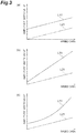
- FIG. 3 is a graph illustrating the threshold line, in which the horizontal axis represents the magnitude of the speed data and the vertical axis represents the magnitude of the amplitude index value.
- a line L21 schematically shows the relationship between the speed data and the amplitude index value in the normal state.
- the normal state means a state in which no irregularity such as a failure of the apparatus or a shortage of the fluid (for example, liquid) to be pressure-fed occurs, or a state in which the bearing is not deteriorated or damaged or the axis of the rotating shaft is not deviated.
- the line L21 is referred to as "normal line L21".
- a line L11 indicates the threshold line. As shown in (a) of FIG. 3 , the threshold line L11 is set so that the amplitude threshold for each value of the speed data is larger than the amplitude index value in the normal state. In other words, the threshold line L11 is set higher than the normal line L21.
- the line L11 is set so that the amplitude threshold increases as the speed data increases.
- the threshold line L11 may be set so that a difference between the amplitude threshold and the amplitude index value in the normal state increases as the speed data increases. In other words, as the speed data increases, the gap between the threshold line L11 and the normal line L 21 may increase.
- the threshold line may be set so as to have a curved relationship with the speed data.
- the threshold setting unit 125 is configured to set the amplitude threshold based on the speed data.
- the threshold setting unit 125 is further configured to increase the amplitude threshold as the speed data increases.
- the threshold setting unit 125 may increase the difference between the amplitude threshold and the amplitude index value in the normal state as the speed data increases. For example, based on the latest speed data acquired by the data acquisition unit 121 and the threshold line stored in the threshold value memory 124, the threshold setting unit 125 may set the amplitude threshold corresponding to the latest speed data.
- the irregularity detection unit 126 is configured to detect irregularity of the pumping apparatus 1 in response to the amplitude index value exceeding the threshold.
- the irregularity detection here merely means to determine that the amplitude threshold is different from normal, and does not necessarily mean to detect the actual occurrence of an irregularity.
- the irregularity detection unit 126 may notify the host controller 300 that irregularity has been detected, or may display it on a display unit (for example, a liquid crystal monitor or a warning lamp) provided in the power conversion apparatus 100.
- the power conversion apparatus 100 may be further configured to generate a threshold line based on user input.
- the power conversion apparatus 100 may further include an input data acquisition unit 131, an input data memory 132, and a line generation unit 133.
- the input data acquisition unit 131 is configured to acquire, from a setting computer 200, input data (hereinafter, "threshold input data") indicating correspondence between a value of speed data and an amplitude threshold corresponding to the value of speed data.
- the input data acquisition unit 131 may be configured to acquire two or more (e.g., three or more) sets of threshold input data having different values of speed data.
- the input data acquisition unit 131 may be configured to limit the range of speed data to which the threshold input data can be input.
- the input data memory 132 is configured to store the threshold input data acquired by the input data acquisition unit 131.
- the line generation unit 133 is configured to generate a threshold line to interpolate between the two or more sets of threshold input data acquired by the input data acquisition unit 131.
- the line generation unit 133 may derive a function based on the two or more sets of threshold input data by a linear function, a polynomial function, a spline function, or the like, or may provide a point sequence between the two or more sets of threshold input data by using these functions.
- the line generation unit 133 may extrapolate the range of the two or more sets of threshold input data by a linear function, a polynomial function, a spline function, or the like. The extrapolation means that a function within a range of the two or more sets of threshold input data is extended and made into a function, or a point sequence is supplemented using the extended function.
- the power conversion apparatus 100 may be further configured to generate a threshold line based on the speed data and the force data in the normal state.
- the power conversion apparatus 100 may be configured to provide electric power for a test operation to the motor 11 and generate the threshold line based on the speed data and the force data acquired during the test operation.
- the power conversion apparatus 100 may further include a scan command memory 141, a scan control unit 142, a test data memory 144, and a line generation unit 145.
- the scan command memory 141 is configured to store a speed command for the test operation for generating the threshold line.
- the speed command includes a plurality of speed command values.
- the scan control unit 142 is configured to provide electric power for test operation by the power conversion unit 111 to the motor 11.
- the scan control unit 142 is configured to provide electric power for operating the motor 11 by the power conversion unit 111 to the motor 11 according to the speed command stored in the scan command memory 141.
- the test data memory 144 is configured to store the speed data acquired during the test operation and the amplitude index value derived by the index value derivation unit 123 based on the force data acquired during the test operation for each of the plurality of speed command values.
- the line generation unit 145 is configured to generate the threshold line based on the speed data and the force data in the normal state.
- the line generation unit 145 may derive a reference line (e.g., line L21 of FIG. 3 ) representing a relationship between the speed data and the amplitude index value in the normal state based on the speed data and the amplitude index value stored in the test data memory 144 in the normal state, and generates the threshold line based on the reference line.
- the line generation unit 145 may generate a line obtained by adding a predetermined margin to the reference line as the threshold line.
- the line generation unit 145 may increase the margin as the speed data increases.
- the gap between the amplitude threshold and the amplitude index value in the normal state increases.
- FIG. 4 is a block diagram illustrating a hardware configuration of the power conversion apparatus 100.
- the power conversion apparatus 100 may include control circuitry 190, switching circuitry 181, and a current sensor 182.
- the control circuitry 190 includes one or more processors 191, memory 192, storage 193, input/output ports 194, and communication ports 195.
- the storage 193 includes a computer-readable storage medium such as a nonvolatile semiconductor memory.
- the storage medium stores a program for configuring each of the above described functional modules of the power conversion apparatus 100.
- the memory 192 temporarily stores a program loaded from the storage medium of the storage 193 and an operation result by the one or more processors 191.
- the one or more processors 191 executes the program in cooperation with the memory 192 to configure each of the functional modules of the power conversion apparatus 100.
- the input/output ports 194 have a terminal block of an input power source, and input and output an electric signal between the switching circuitry 181 and the current sensor 182 in accordance with a command from the one or more processors 191.
- the communication ports 195 perform information communication with the setting computer 200 and the host controller 300 according to an instruction from the one or more processors 191.
- control circuitry 190 is not necessarily limited to one that configures each function by a program.
- at least a part of the functions of the control circuitry 190 may be configured by a dedicated logic circuit or an application specific integrated circuit (ASIC) in which the dedicated logic circuit is integrated.
- ASIC application specific integrated circuit
- the switching circuitry 181 operates in accordance with a command from the control circuitry 190 (for example, an electric signal from the input/output ports 194), and functions as the power conversion unit 111.
- the switching circuitry 181 outputs the driving electric power to the motor 11 by switching on and off a plurality of switching elements in accordance with an electric signal (for example, a gate signal) from the input/output port 194.
- the switching element is, for example, a power metal oxide semiconductor field effect transistor (MOSFET) or an insulated gate bipolar transistor (IGBT).
- the current sensor 182 operates in accordance with a command from the control circuitry 190 (for example, an electric signal from the input/output port 194), and functions as the above-described current detection unit 114.
- the current sensor 182 detects the output current from the switching circuitry 181 to the motor 11.
- control sequence executed by the power conversion apparatus 100 will be described as an example of the control method.
- control sequence is divided into a generation sequence of the threshold line and an operation status monitor sequence, which will be described in detail.
- the power conversion apparatus 100 first executes steps S01, S02, and S03.
- step S01 the input data acquisition unit 131 displays a screen for acquiring the threshold input data (hereinafter, "threshold input screen") on the setting computer 200.
- step S02 the input data acquisition unit 131 waits for an instruction to register the threshold input data input to the threshold input screen. This registration instruction is input, for example, by operating (for example, clicking or tapping) a button on the threshold input screen in the setting computer 200.
- the input data acquisition unit 131 acquires threshold input data input to the threshold input screen from the setting computer 200 and stores the threshold input data in the input data memory 132.
- step S04 the line generation unit 133 checks whether a sets of threshold input data necessary for generation of the threshold line has been acquired.
- step S04 If it is determined in step S04 that the sets of threshold input data necessary for generation of the threshold line has not been acquired, the power conversion apparatus 100 returns the process to step S01. Thereafter, the acquisition of the threshold input data by the input data acquisition unit 131 is repeated until the sets of threshold input data necessary for the generation of the threshold line is acquired.
- step S05 the line generation unit 133 generates a threshold line so as to interpolate between the sets of threshold input data acquired by the input data acquisition unit 131, and stores the generated threshold line in the threshold value memory 124. Then the generation sequence of the threshold line is completed.
- step S11 the speed control unit 112 waits for an operation start command of the motor 11 from the host controller 300 or the like.
- step S12 the speed control unit 112 controls the power conversion unit 111 according to a command or the like from the host controller 300 to start the motor 11. For example, the speed control unit 112 starts the output of driving electric power by the power conversion unit 111 to the motor 11. Thereafter, the speed control unit 112 controls the power conversion unit 111 to output the driving electric power so that the driving speed of the pump 20 follows the target speed.
- step S13 the data acquisition unit 121 acquires the speed data and the force data and stores them in the operation data memory 122.
- the index value derivation unit 123 checks whether or not the number of data sets required for deriving the amplitude index value (hereinafter simply referred to as the "required number") is stored in the operation data memory 122. If it is determined that the number of data sets accumulated in the operation data memory 122 has not reached the required number, the power conversion apparatus 100 returns the process to step S13. Thereafter, the acquisition and storage of the speed data and the force data are repeated until the required number of data sets are accumulated in the operation data memory 122.
- step S15 the index value derivation unit 123 derives the amplitude index value based on the force data stored in the operation data memory 122.
- step S16 based on the latest speed data acquired by the data acquisition unit 121 and the threshold line stored in the threshold value memory 124, the threshold setting unit 125 sets the amplitude threshold corresponding to the latest speed data.
- step S17 the irregularity detection unit 126 checks whether the amplitude index value derived in step S15 exceeds the amplitude threshold set in step S16. If it is determined that the amplitude index value exceeds the amplitude threshold, the power conversion apparatus 100 executes step S18. In step S18, the irregularity detection unit 126 notifies the host controller 300 that irregularity has been detected.
- step S19 the power conversion apparatus 100 executes step S19. If it is determined in step S17 that the amplitude index value does not exceed the amplitude threshold, the power conversion apparatus 100 executes step S19 without executing step S18.
- step S19 the speed control unit 112 checks whether there is a stop command of the motor 11 from the host controller 300 or the like. If it is determined in step S19 that there is no stop command, the power conversion apparatus 100 returns the process to step S13. Thereafter, the monitoring of the operation state of the pumping apparatus 1 is continued until there is a stop command of the motor 11. If it is determined in step S19 that there is a stop command, the power conversion apparatus 100 executes step S21.
- step S21 the speed control unit 112 controls the power conversion unit 111 to stop the motor 11. For example, the speed control unit 112 stops the output of the driving electric power by the power conversion unit 111 to the motor 11. Then the operation status monitor sequence is completed.
- the power conversion apparatus 100 first, executes steps S31, S32, and S33.
- step S31 the scan control unit 142 waits for a test operation start command of the motor 11 from the host controller 300 or the like.
- step S32 the scan control unit 142 sets the target speed of the motor 11 to the initial speed.
- the scan control unit 142 sets the minimum value of the plurality of speed command values stored in the scan command memory 141 as the target speed.
- step S33 the scan control unit 142 requests the speed control unit 112 to start the speed control of the motor 11.
- the speed control unit 112 starts outputting the driving electric power by the power conversion unit 111 to the motor 11. Thereafter, the speed control unit 112 controls the power conversion unit 111 to output the driving electric power so that the driving speed of the pump 20 follows the target speed.
- step S36 the index value derivation unit 123 derives the amplitude index value based on the force data stored in the operation data memory 122.
- step S37 the scan control unit 142 checks whether a predetermined sampling period has elapsed. If it is determined that the sampling period has not elapsed, the power conversion apparatus 100 returns the process to step S34. Thereafter, the acquisition of data and the derivation of the amplitude index value are repeated at a constant target speed until the sampling period elapses.
- step S38 the index value derivation unit 123 stores the maximum value of the amplitude index value calculated during the sampling period and the speed data in the test data memory 144 in association with each other.
- step S39 the scan control unit 142 checks whether the target speed of the motor 11 reaches a final speed.
- the final speed is, for example, the maximum value of the plurality of speed command values stored in the scan command memory 141. If it is determined that the target speed of the motor 11 has not reached the final speed, the power conversion apparatus 100 executes step S41.
- step S41 the scan control unit 142 changes the target speed. For example, the scan control unit 142 sets, as the next target speed, a speed command value that is next to the speed command value currently set as the target speed in ascending order. Thereafter, the power conversion apparatus 100 returns the process to step S34. Thereafter, the amplitude index value and the speed data are stored in the test data memory 144 for each speed command value until it is determined that the target speed has reached the final speed.
- step S41 If it is determined in step S41 that the target speed has reached a final speed, the power conversion apparatus 100 executes steps S42 and S43.
- step S42 the scan control unit 142 requests the speed control unit 112 to stop the motor 11.
- the speed control unit 112 stops the output of the driving electric power by the power conversion unit 111 to the motor 11.
- step S43 the line generation unit 145 derives the reference line based on the speed data and the amplitude index value stored in the test data memory 144, and generates the threshold line based on the reference line.
- the line generation unit 145 stores the generated threshold line in the threshold value memory 124. Then the setting of the threshold line is completed.
- the power conversion apparatus 100 includes the power conversion unit 111 configured to provide electric power to the pumping apparatus 1, the data acquisition unit 121 configured to acquire speed data associated with the driving speed of the pumping apparatus 1 and force data associated with the driving force of the pumping apparatus 1, the threshold setting unit 125 configured to set the threshold of the amplitude index value associated with the vibration amplitude of the force data, and the irregularity detection unit 126 configured to detect the irregularity of the drive object in response to the amplitude index value exceeding the threshold, wherein the threshold setting unit 125 increases the threshold as the speed data increases.
- the power conversion apparatus 100 irregularity is detected based on the amplitude of vibration of the force data.
- the relationship between the speed data and the force data may vary depending on the installation environment of the pumping apparatus 1.
- the amplitude of vibration tends to increase as the speed data increases.
- the threshold setting unit 125 increases the amplitude threshold as the speed data increases.
- the threshold setting unit 125 may increase the difference between the threshold and the amplitude index value in the normal state as the speed data increases. In this case, it is possible to more reliably achieve both suppression of erroneous detection of irregularity in the high-speed region and improvement of detection sensitivity in the low-speed region.
- the power conversion apparatus 100 may further include the threshold value memory 124 configured to store the preset threshold line representing the relationship between the speed data and the threshold, and the threshold setting unit 125 may set the threshold based on the speed data and the threshold line L11. In this case, based on the threshold line, the amplitude threshold can be quickly set with a small calculation load.
- the power conversion apparatus 100 may further include a line generation unit 145 configured to set the threshold line L11 based on the speed data and the force data in the normal state. In this case, the generation of the threshold line L11 is also executed by the power conversion apparatus 100. Therefore, the irregular detect function can be more easily constructed.
- the line generation unit 145 may derive the reference line L21 indicating the relationship between the speed data and the amplitude index value in the normal state based on the speed data and the force data in the normal state, and generate the threshold line L11 based on the reference line L21. In this case, it is possible to more reliably achieve both suppression of erroneous detection of irregularity and improvement of detection sensitivity in each speed range.
- the power conversion apparatus 100 may further include a scan control unit 142 for providing electric power for a test operation from the power conversion unit 111 to the drive object, and the line generation unit 145 may generate the threshold line L11 based on speed data and force data acquired during the test operation.
- a preset test operation for setting the threshold line L11 is automatically executed by the power conversion apparatus 100. Therefore, the irregular detect function can be more easily constructed.
- the power conversion apparatus 100 may further include an index value derivation unit 123 configured to derive amplitude of vibration as an amplitude index value based on a plurality of force data acquired during a period from a predetermined length of time before the acquisition time of the force data to the acquisition time.
- an index value derivation unit 123 configured to derive amplitude of vibration as an amplitude index value based on a plurality of force data acquired during a period from a predetermined length of time before the acquisition time of the force data to the acquisition time.
- the relationship with the amplitude threshold is confirmed after the amplitude itself is derived. Therefore, irregularity of the drive object can be detected with higher reliability.
- the power conversion apparatus 100 may further include an index value derivation unit 123 configured to derive, as the amplitude index value, the difference between the force data and the trend value of the force data based on the past values of force data acquired during a period from a predetermined length of time before the acquisition time of the force data to the acquisition time.
- an index value derivation unit 123 configured to derive, as the amplitude index value, the difference between the force data and the trend value of the force data based on the past values of force data acquired during a period from a predetermined length of time before the acquisition time of the force data to the acquisition time.
- the diagnostic apparatus of the pumping apparatus 1 configured to acquire force data associated with the driving force of the pumping apparatus 1 based on the electric power provided to the pumping apparatus 1 by the power conversion unit 111, set the threshold of the amplitude index value associated with the vibration amplitude of the force data, and detect the irregularity of the pumping apparatus 1 in response to the amplitude index value exceeding the threshold, wherein the threshold is increased as a driving speed of the drive object increases, is incorporated in the power conversion apparatus 100 of the pumping apparatus 1.
- the diagnostic apparatus may be configured outside the pumping apparatus 1.
- the diagnostic apparatus 400 shown in FIG. 8 is configured outside the pumping apparatus 1, and includes the data acquisition unit 121, the operation data memory 122, the index value derivation unit 123, the threshold value memory 124, the threshold setting unit 125, the irregularity detection unit 126, the input data acquisition unit 131, the input data memory 132, the line generation unit 133, the scan command memory 141, the scan control unit 142, and the test data memory 144.
- the diagnostic apparatus may be incorporated in the host controller 300.
- the electric drive object is not limited to the pumping apparatus 1.
- the electric drive object may be any object that uses an electric motor as a power source, such as a fan or a stirrer.
- the motor itself may be an electric drive object. In this case, it is possible to detect irregularity such as deterioration or damage of the bearing of the motor itself.
- pumping apparatus electric drive object
- 13 electrical component holder
- 20 pump
- 100 power conversion apparatus
- 111 power conversion unit
- 121 data acquisition unit
- 123 index value derivation unit
- 124 threshold value memory
- 125 threshold setting unit
- 126 irregularity detection unit
- 145 line generation unit
- 142 scan control unit
- 400 diagnostic apparatus
- L11 threshold line
- L21 normal line (reference line).
Landscapes
- Engineering & Computer Science (AREA)
- Power Engineering (AREA)
- Physics & Mathematics (AREA)
- General Physics & Mathematics (AREA)
- Mechanical Engineering (AREA)
- General Engineering & Computer Science (AREA)
- Control Of Electric Motors In General (AREA)
- Arrangements For Transmission Of Measured Signals (AREA)
Abstract
Description
- The present disclosure relates to a power conversion apparatus, a pumping apparatus, a control method, a diagnostic apparatus, and a diagnostic method.
-
Patent Document 1 discloses an inverter apparatus including means for quickly stopping the inverter apparatus and outputting an alarm when a motor current output to a motor for driving a pump decreases to reach a preset no-load motor current value and the motor current does not increase even after a lapse of a preset time. - [Patent Document 1]
Japanese Unexamined Patent Publication No. H6 (1994)-165521 - The present disclosure provides a power conversion apparatus, a pumping apparatus, a control method, a diagnostic apparatus, and a diagnostic method capable of easily constituting an irregular detect function of a drive object.
- A power conversion apparatus according to an aspect of the present disclosure includes: a power conversion unit configured to provide electric power to an electric drive object; a data acquisition unit configured to acquire speed data associated with driving speed of the drive object and force data associated with driving force of the drive object; a threshold setting unit configured to set a threshold of an amplitude index value associated with vibration amplitude of the force data; and an irregularity detection unit configured to detect irregularity of the drive object in response to the amplitude index value exceeding the threshold, wherein the threshold setting unit increases the threshold as the speed data increases.
- A pumping apparatus according to another aspect of the present disclosure includes the power conversion apparatus and an electric pump driven by electric power provided by the power conversion apparatus.
- A control method according to another aspect of the present disclosure includes: providing electric power to an electric drive object; acquiring speed data associated with a driving speed of the drive object and force data associated with a driving force of the drive object; setting a threshold of an amplitude index value associated with an amplitude of vibration of the force data; and detecting irregularity of the drive object in response to the amplitude index value exceeding the threshold, wherein the threshold is increased as a driving speed of the drive object increases.
- A diagnostic apparatus according to another aspect of the present disclosure includes: a data acquisition unit configured to acquire force data associated with a driving force of an electric drive object based on electric power provided to the drive object by a power conversion unit; a threshold setting unit configured to set a threshold of an amplitude index value associated with an amplitude of vibration of the force data; and an irregularity detection unit configured to detect irregularity of the drive object in response to the amplitude index value exceeding the threshold, wherein the threshold setting unit increases the threshold as the speed data increases.
- A diagnostic method according to another aspect of the present disclosure includes; acquiring force data associated with a driving force of an electric drive object based on electric power provided to the drive object by a power conversion unit; setting a threshold of an amplitude index value associated with an amplitude of vibration of the force data; and detecting irregularity of the drive object in response to the amplitude index value exceeding the threshold, wherein the threshold is increased as a driving speed of the drive object increases.
- According to the present disclosure, an apparatus capable of easily constructing an irregular detect function of a drive object can be provided.
-
-
FIG. 1 is a side view of a pumping apparatus. -
FIG. 2 is a block diagram showing a functional configuration of a power conversion apparatus. -
FIG. 3 is a graph illustrating a threshold line. -
FIG. 4 is a hardware configuration diagram of the power conversion apparatus. -
FIG. 5 is a flowchart showing a generation sequence of the threshold line. -
FIG. 6 is a flowchart showing an operation status monitor sequence. -
FIG. 7 is a flowchart showing a modification of the generation sequence of the threshold line. -
FIG. 8 is a block diagram showing a modification of a diagnostic apparatus. - Hereinafter, embodiments will be described in detail with reference to the drawings. In the description, the same element or the element having the same function is denoted by the same reference numeral, and the overlapping description is omitted.
- The
pumping apparatus 1 shown inFIG. 1 includes apump 20 configured to pump liquid, apump driving apparatus 10 configured to drive thepump 20, and aunit base 2 configured to integrally hold these components. - The
pump 20 is a non-positive displacement rotary pump. For example, thepump 20 is a centrifugal pump such as a spiral pump, and includes animpeller 21 that pumps liquid by centrifugal force. Thepump 20 may be a positive displacement pump or a reciprocating pump such as a diaphragm pump or a bellows pump. Thepump 20 may be any pump as long as the relationship between the driving speed and the driving force during the steady operation is reproducible. - The
pump driving apparatus 10 includes amotor 11, apower conversion apparatus 100, and anelectrical component holder 13. Themotor 11 is a power source for driving thepump 20. Specific examples of themotor 11 include a rotary synchronous motor or an induction motor. - The
power conversion apparatus 100 generates alternating-current electric power to control a rotating speed of themotor 11 to follow a frequency command (speed command) received from a host controller 300 (seeFIG. 2 ). Thepower conversion apparatus 100 may generate a frequency command by an internal operation instead of reception from thehost controller 300, or may store a preset frequency command therein. The configuration of thepower conversion apparatus 100 will be described in detail later. - The
electrical component holder 13 is fixed to themotor 11 and holds thepower conversion apparatus 100. For example, theelectrical component holder 13 is a case fixed to the outer periphery of the frame of themotor 11 and holds thepower conversion apparatus 100 therein. - The
power conversion apparatus 100 is configured to: provide electric power to the pumping apparatus 1 (electric drive object); acquire speed data associated with a driving speed of thepumping apparatus 1 and force data associated with a driving force of thepumping apparatus 1; set a threshold of an amplitude index value associated with an amplitude of vibration of the force data; and detect irregularity of thepumping apparatus 1 in response to the amplitude index value exceeding the threshold. For example, as shown inFIG. 2 , apower conversion apparatus 100 includes, as functional elements (here in after "functional modules"), apower conversion unit 111, aspeed control unit 112, acurrent control unit 113, acurrent detection unit 114, adata acquisition unit 121, anoperation data memory 122, an indexvalue derivation unit 123, athreshold value memory 124, athreshold setting unit 125, and anirregularity detection unit 126. - The
power conversion unit 111 is configured to output driving electric power to themotor 11 of thepumping apparatus 1. For example, thepower conversion unit 111 is configured to output an alternating voltage having a frequency capable of following the magnetic pole of themotor 11 to themotor 11 at a voltage amplitude corresponding to a voltage command. For example, thepower conversion unit 111 is configured to generate the alternating voltage by pulse width modulation (PWM). Thepower conversion unit 111 may be an inverter configured to convert direct-current electric power of a direct-current bus into alternating-current electric power to generate driving electric power, or may be a matrix converter configured to performs bidirectional electric power conversion between alternating-current electric power on an alternating power source side and alternating-current electric power on themotor 11 side. - The
speed control unit 112 is configured to control thepower conversion unit 111 to output driving electric power so that the driving speed of thepump 20 follows a target speed. The target speed is, for example, the frequency command received from thehost controller 300. The target speed may be the frequency command generated by an internal operation of thepower conversion apparatus 100 or may be the preset frequency command stored in thepower conversion apparatus 100. Thespeed control unit 112 calculates a current command (torque command) for reducing a speed deviation. - The
current control unit 113 is configured to calculate a voltage command for reducing a deviation between the current command calculated by thespeed control unit 112 and a current (hereinafter, "output current") being output to themotor 11, and output the voltage command to thepower conversion unit 111. Accordingly, thepower conversion unit 111 outputs driving electric power to themotor 11 so that the driving speed of thepump 20 follows the target speed. Thecurrent detection unit 114 detects the output current from thepower conversion unit 111 to themotor 11. - The
data acquisition unit 121 is configured to acquire speed data associated with the driving speed of thepumping apparatus 1 and force data associated with the driving force of thepumping apparatus 1. The speed data may be any data as long as it is associated with the driving speed of the pumping apparatus 1 (for example, the rotating speed of the motor 11). Here, "associate" means that speed data increases or decreases in accordance with an increase or decrease in driving speed. Specific examples of the speed data include a command value of the rotating speed of themotor 11 or a frequency command value of alternating-current electric power provided to themotor 11. The speed data may be a detected value of the rotating speed of themotor 11 detected by a sensor such as a pulse generator. - The force data may be any data as long as it is associated with the driving force of the pumping apparatus 1 (e.g., the torque of the motor 11). Here, "associate" means that the force data increases or decreases in accordance with an increase or decrease in the driving force. A specific example of the force data is a detected value of current provided to the motor 11 (for example, a detected value by the current detection unit 114). The force data may be a command value of current provided to the
motor 11 or may be a torque detection value by a force sensor. - The
operation data memory 122 is configured to store the speed data and the force data acquired by thedata acquisition unit 121 in chronological order. - The index
value derivation unit 123 is configured to derive the amplitude index value based on the force data stored in theoperation data memory 122. The amplitude index value may be any data as long as it is associated with the amplitude of vibration of the force data. Here, "associate" means that the amplitude index value increases or decreases in accordance with an increase or decrease in amplitude. - For example, the index
value derivation unit 123 derives the amplitude of the vibration of the force data as the amplitude index value based on a plurality of values of the force data acquired during a period from a predetermined length of time before an acquisition time of the force data to the acquisition time. The amplitude may be a width from a negative peak to a positive peak, or may be a half of the width from the negative peak to the positive peak. The vibration is a vibration of the force data in a steady operation of thepumping apparatus 1. The steady operation refers to an operation state in which thepump 20 is filled with liquid to be pumped (hereinafter simply referred to as "liquid") and the driving speed of thepump 20 substantially consistent with the target speed. Substantially consistent means that the difference between the driving speed and the target speed is within a negligible margin of error. The amplitude may be obtained from, for example, a difference between a maximum value and a minimum value within a predetermined time, or may be obtained by fast Fourier transform (FFT). For example, the indexvalue derivation unit 123 may derive the amplitude of a predetermined frequency as the amplitude index value by FFT, or may derive an average value, a maximum value, or the like of the amplitude in a predetermined band of frequency as the amplitude index value. - The index
value derivation unit 123 may derive, as the amplitude index value, a difference between the force data and a trend value of the force data based on past values of force data acquired during a period from a predetermined length of time before an acquisition time of the force data to the acquisition time. For example, the indexvalue derivation unit 123 may derive the trend value by low-pass filtering using the past values of force data on the latest force data in theoperation data memory 122 to calculate the trend value. - As a specific example of the low-pass type filtering, there is a finite impulse response type filtering. When a first order filtering of the finite impulse response method is used, the trend value is derived by the following expression.

- Y: trend value
- X [k]: latest force data
- X [k-1]: previously acquired force data
- A: filter coefficient
- When a second order filtering of the finite impulse response method is used, the trend value is derived by the following expression.

- Y: trend value
- X [k]: latest force data
- X [k-1]: previously acquired force data
- X [k - 2]: acquired force data two times before
- A and B: filter coefficients
- The index
value derivation unit 123 may not necessarily use the latest force data for calculating the trend value, and may calculate the trend value based only on the past values of force data. For example, X [k] may be force data acquired one or more (for example, one) times before the latest. - The
threshold value memory 124 is configured to store a preset threshold line representing a relationship between the speed data and the threshold of the amplitude index value. Hereinafter, the threshold of the amplitude index value is referred to as "amplitude threshold". The amplitude threshold is, for example, an upper limit value that is set to a level at which it can be determined that the state is not normal when the amplitude threshold exceeds the value. Thethreshold value memory 124 may store the threshold line as a point sequence arranged on the line, or may store the threshold line as a function. -
FIG. 3 is a graph illustrating the threshold line, in which the horizontal axis represents the magnitude of the speed data and the vertical axis represents the magnitude of the amplitude index value. A line L21 schematically shows the relationship between the speed data and the amplitude index value in the normal state. The normal state means a state in which no irregularity such as a failure of the apparatus or a shortage of the fluid (for example, liquid) to be pressure-fed occurs, or a state in which the bearing is not deteriorated or damaged or the axis of the rotating shaft is not deviated. Hereinafter, the line L21 is referred to as "normal line L21". A line L11 indicates the threshold line. As shown in (a) ofFIG. 3 , the threshold line L11 is set so that the amplitude threshold for each value of the speed data is larger than the amplitude index value in the normal state. In other words, the threshold line L11 is set higher than the normal line L21. - As shown in
FIG. 3 , the line L11 is set so that the amplitude threshold increases as the speed data increases. As shown in (b) ofFIG. 3 , the threshold line L11 may be set so that a difference between the amplitude threshold and the amplitude index value in the normal state increases as the speed data increases. In other words, as the speed data increases, the gap between the threshold line L11 and thenormal line L 21 may increase. As shown in (c) ofFIG. 3 , the threshold line may be set so as to have a curved relationship with the speed data. - The
threshold setting unit 125 is configured to set the amplitude threshold based on the speed data. Thethreshold setting unit 125 is further configured to increase the amplitude threshold as the speed data increases. Thethreshold setting unit 125 may increase the difference between the amplitude threshold and the amplitude index value in the normal state as the speed data increases. For example, based on the latest speed data acquired by thedata acquisition unit 121 and the threshold line stored in thethreshold value memory 124, thethreshold setting unit 125 may set the amplitude threshold corresponding to the latest speed data. - The
irregularity detection unit 126 is configured to detect irregularity of thepumping apparatus 1 in response to the amplitude index value exceeding the threshold. The irregularity detection here merely means to determine that the amplitude threshold is different from normal, and does not necessarily mean to detect the actual occurrence of an irregularity. Theirregularity detection unit 126 may notify thehost controller 300 that irregularity has been detected, or may display it on a display unit (for example, a liquid crystal monitor or a warning lamp) provided in thepower conversion apparatus 100. - The
power conversion apparatus 100 may be further configured to generate a threshold line based on user input. For example, as shown inFIG. 2 , thepower conversion apparatus 100 may further include an inputdata acquisition unit 131, aninput data memory 132, and aline generation unit 133. The inputdata acquisition unit 131 is configured to acquire, from a settingcomputer 200, input data (hereinafter, "threshold input data") indicating correspondence between a value of speed data and an amplitude threshold corresponding to the value of speed data. The inputdata acquisition unit 131 may be configured to acquire two or more (e.g., three or more) sets of threshold input data having different values of speed data. The inputdata acquisition unit 131 may be configured to limit the range of speed data to which the threshold input data can be input. Theinput data memory 132 is configured to store the threshold input data acquired by the inputdata acquisition unit 131. - The
line generation unit 133 is configured to generate a threshold line to interpolate between the two or more sets of threshold input data acquired by the inputdata acquisition unit 131. For example, theline generation unit 133 may derive a function based on the two or more sets of threshold input data by a linear function, a polynomial function, a spline function, or the like, or may provide a point sequence between the two or more sets of threshold input data by using these functions. Further, theline generation unit 133 may extrapolate the range of the two or more sets of threshold input data by a linear function, a polynomial function, a spline function, or the like. The extrapolation means that a function within a range of the two or more sets of threshold input data is extended and made into a function, or a point sequence is supplemented using the extended function. - The
power conversion apparatus 100 may be further configured to generate a threshold line based on the speed data and the force data in the normal state. In this case, thepower conversion apparatus 100 may be configured to provide electric power for a test operation to themotor 11 and generate the threshold line based on the speed data and the force data acquired during the test operation. For example, thepower conversion apparatus 100 may further include ascan command memory 141, ascan control unit 142, atest data memory 144, and aline generation unit 145. - The
scan command memory 141 is configured to store a speed command for the test operation for generating the threshold line. The speed command includes a plurality of speed command values. Thescan control unit 142 is configured to provide electric power for test operation by thepower conversion unit 111 to themotor 11. For example, thescan control unit 142 is configured to provide electric power for operating themotor 11 by thepower conversion unit 111 to themotor 11 according to the speed command stored in thescan command memory 141. Thetest data memory 144 is configured to store the speed data acquired during the test operation and the amplitude index value derived by the indexvalue derivation unit 123 based on the force data acquired during the test operation for each of the plurality of speed command values. - The
line generation unit 145 is configured to generate the threshold line based on the speed data and the force data in the normal state. For example, theline generation unit 145 may derive a reference line (e.g., line L21 ofFIG. 3 ) representing a relationship between the speed data and the amplitude index value in the normal state based on the speed data and the amplitude index value stored in thetest data memory 144 in the normal state, and generates the threshold line based on the reference line. For example, theline generation unit 145 may generate a line obtained by adding a predetermined margin to the reference line as the threshold line. Theline generation unit 145 may increase the margin as the speed data increases. Thus, as the speed data increases, the gap between the amplitude threshold and the amplitude index value in the normal state increases. -
FIG. 4 is a block diagram illustrating a hardware configuration of thepower conversion apparatus 100. As shown inFIG. 4 , thepower conversion apparatus 100 may includecontrol circuitry 190, switchingcircuitry 181, and acurrent sensor 182. - The
control circuitry 190 includes one ormore processors 191,memory 192,storage 193, input/output ports 194, andcommunication ports 195. Thestorage 193 includes a computer-readable storage medium such as a nonvolatile semiconductor memory. The storage medium stores a program for configuring each of the above described functional modules of thepower conversion apparatus 100. Thememory 192 temporarily stores a program loaded from the storage medium of thestorage 193 and an operation result by the one ormore processors 191. The one ormore processors 191 executes the program in cooperation with thememory 192 to configure each of the functional modules of thepower conversion apparatus 100. The input/output ports 194 have a terminal block of an input power source, and input and output an electric signal between the switchingcircuitry 181 and thecurrent sensor 182 in accordance with a command from the one ormore processors 191. Thecommunication ports 195 perform information communication with the settingcomputer 200 and thehost controller 300 according to an instruction from the one ormore processors 191. - It should be noted that the
control circuitry 190 is not necessarily limited to one that configures each function by a program. For example, at least a part of the functions of thecontrol circuitry 190 may be configured by a dedicated logic circuit or an application specific integrated circuit (ASIC) in which the dedicated logic circuit is integrated. - The switching
circuitry 181 operates in accordance with a command from the control circuitry 190 (for example, an electric signal from the input/output ports 194), and functions as thepower conversion unit 111. For example, the switchingcircuitry 181 outputs the driving electric power to themotor 11 by switching on and off a plurality of switching elements in accordance with an electric signal (for example, a gate signal) from the input/output port 194. The switching element is, for example, a power metal oxide semiconductor field effect transistor (MOSFET) or an insulated gate bipolar transistor (IGBT). - The
current sensor 182 operates in accordance with a command from the control circuitry 190 (for example, an electric signal from the input/output port 194), and functions as the above-describedcurrent detection unit 114. Thecurrent sensor 182 detects the output current from the switchingcircuitry 181 to themotor 11. - Next, a control sequence executed by the
power conversion apparatus 100 will be described as an example of the control method. Hereinafter, the control sequence is divided into a generation sequence of the threshold line and an operation status monitor sequence, which will be described in detail. - As shown in
FIG. 5 , thepower conversion apparatus 100 first executes steps S01, S02, and S03. In step S01, the inputdata acquisition unit 131 displays a screen for acquiring the threshold input data (hereinafter, "threshold input screen") on the settingcomputer 200. In step S02, the inputdata acquisition unit 131 waits for an instruction to register the threshold input data input to the threshold input screen. This registration instruction is input, for example, by operating (for example, clicking or tapping) a button on the threshold input screen in the settingcomputer 200. In step S03, the inputdata acquisition unit 131 acquires threshold input data input to the threshold input screen from the settingcomputer 200 and stores the threshold input data in theinput data memory 132. - Next, the
power conversion apparatus 100 executes step S04. In step S04, theline generation unit 133 checks whether a sets of threshold input data necessary for generation of the threshold line has been acquired. - If it is determined in step S04 that the sets of threshold input data necessary for generation of the threshold line has not been acquired, the
power conversion apparatus 100 returns the process to step S01. Thereafter, the acquisition of the threshold input data by the inputdata acquisition unit 131 is repeated until the sets of threshold input data necessary for the generation of the threshold line is acquired. - If it is determined in step S04 that the sets of threshold input data necessary for generation of the threshold line has been acquired, the
power conversion apparatus 100 executes step S05. In step S05, theline generation unit 133 generates a threshold line so as to interpolate between the sets of threshold input data acquired by the inputdata acquisition unit 131, and stores the generated threshold line in thethreshold value memory 124. Then the generation sequence of the threshold line is completed. - As shown in
FIG. 6 , thepower conversion apparatus 100 executes steps S11 and S12. In step S11, thespeed control unit 112 waits for an operation start command of themotor 11 from thehost controller 300 or the like. In step S12, thespeed control unit 112 controls thepower conversion unit 111 according to a command or the like from thehost controller 300 to start themotor 11. For example, thespeed control unit 112 starts the output of driving electric power by thepower conversion unit 111 to themotor 11. Thereafter, thespeed control unit 112 controls thepower conversion unit 111 to output the driving electric power so that the driving speed of thepump 20 follows the target speed. - Next, the
power conversion apparatus 100 executes steps S13 and S14. In step S13, thedata acquisition unit 121 acquires the speed data and the force data and stores them in theoperation data memory 122. In step S14, the indexvalue derivation unit 123 checks whether or not the number of data sets required for deriving the amplitude index value (hereinafter simply referred to as the "required number") is stored in theoperation data memory 122. If it is determined that the number of data sets accumulated in theoperation data memory 122 has not reached the required number, thepower conversion apparatus 100 returns the process to step S13. Thereafter, the acquisition and storage of the speed data and the force data are repeated until the required number of data sets are accumulated in theoperation data memory 122. - If it is determined in step S14 that the necessary number of data sets have been accumulated in the
operation data memory 122, thepower conversion apparatus 100 executes steps S15 and S16. In step S15, the indexvalue derivation unit 123 derives the amplitude index value based on the force data stored in theoperation data memory 122. In step S16, based on the latest speed data acquired by thedata acquisition unit 121 and the threshold line stored in thethreshold value memory 124, thethreshold setting unit 125 sets the amplitude threshold corresponding to the latest speed data. - Next, the
power conversion apparatus 100 executes step S17. In step S17, theirregularity detection unit 126 checks whether the amplitude index value derived in step S15 exceeds the amplitude threshold set in step S16. If it is determined that the amplitude index value exceeds the amplitude threshold, thepower conversion apparatus 100 executes step S18. In step S18, theirregularity detection unit 126 notifies thehost controller 300 that irregularity has been detected. - Next, the
power conversion apparatus 100 executes step S19. If it is determined in step S17 that the amplitude index value does not exceed the amplitude threshold, thepower conversion apparatus 100 executes step S19 without executing step S18. In step S19, thespeed control unit 112 checks whether there is a stop command of themotor 11 from thehost controller 300 or the like. If it is determined in step S19 that there is no stop command, thepower conversion apparatus 100 returns the process to step S13. Thereafter, the monitoring of the operation state of thepumping apparatus 1 is continued until there is a stop command of themotor 11. If it is determined in step S19 that there is a stop command, thepower conversion apparatus 100 executes step S21. In step S21, thespeed control unit 112 controls thepower conversion unit 111 to stop themotor 11. For example, thespeed control unit 112 stops the output of the driving electric power by thepower conversion unit 111 to themotor 11. Then the operation status monitor sequence is completed. - Modification of Threshold Line Generation Sequence Next, a modification of the generation sequence of the threshold line will be described. As shown in
FIG. 7 , thepower conversion apparatus 100, first, executes steps S31, S32, and S33. In step S31, thescan control unit 142 waits for a test operation start command of themotor 11 from thehost controller 300 or the like. In step S32, thescan control unit 142 sets the target speed of themotor 11 to the initial speed. For example, thescan control unit 142 sets the minimum value of the plurality of speed command values stored in thescan command memory 141 as the target speed. In step S33, thescan control unit 142 requests thespeed control unit 112 to start the speed control of themotor 11. Thespeed control unit 112 starts outputting the driving electric power by thepower conversion unit 111 to themotor 11. Thereafter, thespeed control unit 112 controls thepower conversion unit 111 to output the driving electric power so that the driving speed of thepump 20 follows the target speed. - Next, the
power conversion apparatus 100 repeats steps S34 and S35 similar to steps S13 and S14 until the required number of datasets are accumulated in theoperation data memory 122. Next, thepower conversion apparatus 100 executes step S36. In step S36, the indexvalue derivation unit 123 derives the amplitude index value based on the force data stored in theoperation data memory 122. - Next, the
power conversion apparatus 100 executes step S37. In step S37, thescan control unit 142 checks whether a predetermined sampling period has elapsed. If it is determined that the sampling period has not elapsed, thepower conversion apparatus 100 returns the process to step S34. Thereafter, the acquisition of data and the derivation of the amplitude index value are repeated at a constant target speed until the sampling period elapses. - Next, the
power conversion apparatus 100 executes step S38. In step S38, the indexvalue derivation unit 123 stores the maximum value of the amplitude index value calculated during the sampling period and the speed data in thetest data memory 144 in association with each other. - Next, the
power conversion apparatus 100 executes step S39. In step S39, thescan control unit 142 checks whether the target speed of themotor 11 reaches a final speed. The final speed is, for example, the maximum value of the plurality of speed command values stored in thescan command memory 141. If it is determined that the target speed of themotor 11 has not reached the final speed, thepower conversion apparatus 100 executes step S41. In step S41, thescan control unit 142 changes the target speed. For example, thescan control unit 142 sets, as the next target speed, a speed command value that is next to the speed command value currently set as the target speed in ascending order. Thereafter, thepower conversion apparatus 100 returns the process to step S34. Thereafter, the amplitude index value and the speed data are stored in thetest data memory 144 for each speed command value until it is determined that the target speed has reached the final speed. - If it is determined in step S41 that the target speed has reached a final speed, the
power conversion apparatus 100 executes steps S42 and S43. In step S42, thescan control unit 142 requests thespeed control unit 112 to stop themotor 11. Thespeed control unit 112 stops the output of the driving electric power by thepower conversion unit 111 to themotor 11. In step S43, theline generation unit 145 derives the reference line based on the speed data and the amplitude index value stored in thetest data memory 144, and generates the threshold line based on the reference line. Theline generation unit 145 stores the generated threshold line in thethreshold value memory 124. Then the setting of the threshold line is completed. - As described above, the
power conversion apparatus 100 includes thepower conversion unit 111 configured to provide electric power to thepumping apparatus 1, thedata acquisition unit 121 configured to acquire speed data associated with the driving speed of thepumping apparatus 1 and force data associated with the driving force of thepumping apparatus 1, thethreshold setting unit 125 configured to set the threshold of the amplitude index value associated with the vibration amplitude of the force data, and theirregularity detection unit 126 configured to detect the irregularity of the drive object in response to the amplitude index value exceeding the threshold, wherein thethreshold setting unit 125 increases the threshold as the speed data increases. - According to the
power conversion apparatus 100, irregularity is detected based on the amplitude of vibration of the force data. The relationship between the speed data and the force data may vary depending on the installation environment of thepumping apparatus 1. On the other hand, in the relationship between the speed data and the amplitude of vibration, it is easy to find out the regularity independent of the installation environment or the like of thepumping apparatus 1. For example, in the normal state, the amplitude of vibration tends to increase as the speed data increases. Accordingly, thethreshold setting unit 125 increases the amplitude threshold as the speed data increases. As a result, it is possible to increase the detection sensitivity of irregularity in the low-speed region while suppressing erroneous detection of irregularity in the high-speed region. In this way, by incorporating in advance a general logic that does not depend on the installation environment or the like, it is possible to reduce individual setting work according to the installation environment or the like. Therefore, the irregular detect function can be easily constructed. - The
threshold setting unit 125 may increase the difference between the threshold and the amplitude index value in the normal state as the speed data increases. In this case, it is possible to more reliably achieve both suppression of erroneous detection of irregularity in the high-speed region and improvement of detection sensitivity in the low-speed region. - The
power conversion apparatus 100 may further include thethreshold value memory 124 configured to store the preset threshold line representing the relationship between the speed data and the threshold, and thethreshold setting unit 125 may set the threshold based on the speed data and the threshold line L11. In this case, based on the threshold line, the amplitude threshold can be quickly set with a small calculation load. - The
power conversion apparatus 100 may further include aline generation unit 145 configured to set the threshold line L11 based on the speed data and the force data in the normal state. In this case, the generation of the threshold line L11 is also executed by thepower conversion apparatus 100. Therefore, the irregular detect function can be more easily constructed. - The
line generation unit 145 may derive the reference line L21 indicating the relationship between the speed data and the amplitude index value in the normal state based on the speed data and the force data in the normal state, and generate the threshold line L11 based on the reference line L21. In this case, it is possible to more reliably achieve both suppression of erroneous detection of irregularity and improvement of detection sensitivity in each speed range. - The
power conversion apparatus 100 may further include ascan control unit 142 for providing electric power for a test operation from thepower conversion unit 111 to the drive object, and theline generation unit 145 may generate the threshold line L11 based on speed data and force data acquired during the test operation. In this case, a preset test operation for setting the threshold line L11 is automatically executed by thepower conversion apparatus 100. Therefore, the irregular detect function can be more easily constructed. - The
power conversion apparatus 100 may further include an indexvalue derivation unit 123 configured to derive amplitude of vibration as an amplitude index value based on a plurality of force data acquired during a period from a predetermined length of time before the acquisition time of the force data to the acquisition time. In this case, the relationship with the amplitude threshold is confirmed after the amplitude itself is derived. Therefore, irregularity of the drive object can be detected with higher reliability. - The
power conversion apparatus 100 may further include an indexvalue derivation unit 123 configured to derive, as the amplitude index value, the difference between the force data and the trend value of the force data based on the past values of force data acquired during a period from a predetermined length of time before the acquisition time of the force data to the acquisition time. In this case, the irregularity of the drive object can be quickly detected even in a situation in which irregularity has occurred suddenly. - Although the embodiments have been described above, the present invention is not necessarily limited to the above-described embodiments, and various modifications can be made without departing from the scope of the invention. In the above embodiment, the diagnostic apparatus of the
pumping apparatus 1 configured to acquire force data associated with the driving force of thepumping apparatus 1 based on the electric power provided to thepumping apparatus 1 by thepower conversion unit 111, set the threshold of the amplitude index value associated with the vibration amplitude of the force data, and detect the irregularity of thepumping apparatus 1 in response to the amplitude index value exceeding the threshold, wherein the threshold is increased as a driving speed of the drive object increases, is incorporated in thepower conversion apparatus 100 of thepumping apparatus 1. The diagnostic apparatus may be configured outside thepumping apparatus 1. For example, thediagnostic apparatus 400 shown inFIG. 8 is configured outside thepumping apparatus 1, and includes thedata acquisition unit 121, theoperation data memory 122, the indexvalue derivation unit 123, thethreshold value memory 124, thethreshold setting unit 125, theirregularity detection unit 126, the inputdata acquisition unit 131, theinput data memory 132, theline generation unit 133, thescan command memory 141, thescan control unit 142, and thetest data memory 144. The diagnostic apparatus may be incorporated in thehost controller 300. The electric drive object is not limited to thepumping apparatus 1. The electric drive object may be any object that uses an electric motor as a power source, such as a fan or a stirrer. The motor itself may be an electric drive object. In this case, it is possible to detect irregularity such as deterioration or damage of the bearing of the motor itself. - 1: pumping apparatus (electric drive object), 13: electrical component holder, 20: pump, 100: power conversion apparatus, 111: power conversion unit, 121: data acquisition unit, 123: index value derivation unit, 124: threshold value memory, 125: threshold setting unit, 126: irregularity detection unit, 145: line generation unit, 142: scan control unit, 400: diagnostic apparatus, L11: threshold line, L21: normal line (reference line).
Claims (13)
- A power conversion apparatus comprising:a power conversion unit configured to provide electric power to an electric drive object;a data acquisition unit configured to acquire speed data associated with a driving speed of the drive object and force data associated with a driving force of the drive object;a threshold setting unit configured to set a threshold of an amplitude index value associated with an amplitude of vibration of the force data; andan irregularity detection unit configured to detect irregularity of the drive object in response to the amplitude index value exceeding the threshold,wherein the threshold setting unit is further configured to increase the threshold as the speed data increases.
- The power conversion apparatus according to claim 1, wherein the threshold setting unit is further configured to increase a difference between the threshold and the amplitude index value in a normal state as the speed data increases.
- The power conversion apparatus according to claim 1 or 2, further comprising a threshold value memory configured to store a preset threshold line representing a relationship between the speed data and the threshold, wherein the threshold setting unit is further configured to set the threshold based on the speed data and the threshold line.
- The power conversion apparatus according to claim 3, further comprising a line generation unit configured to generate the threshold line based on the speed data and the force data in a normal state.
- The power conversion apparatus according to claim 4, wherein the line generation unit is further configured to derive a reference line representing a relationship between the speed data and the amplitude index value in the normal state based on the speed data and the force data in the normal state, and generate the threshold line based on the reference line.
- The power conversion apparatus according to claim 4 or 5, further comprising a scan control unit configured to provide electric power for a test operation by the power conversion unit to the drive object,
wherein the line generation unit is further configured to generate the threshold line based on the speed data and the force data acquired during the test operation. - The power conversion apparatus according to any one of claims 1 to 6, further comprising an index value derivation unit configured to derive the amplitude of the vibration as the amplitude index value based on a plurality of values of the force data acquired during a period from a predetermined length of time before an acquisition time of the force data to the acquisition time.
- The power conversion apparatus according to any one of claims 1 to 6, further comprising:
an index value derivation unit configured to derive, as the amplitude index value, a difference between the force data and a trend value of the force data based on past values of force data acquired during a period from a predetermined length of time before an acquisition time of the force data to the acquisition time. - A pumping apparatus comprising:the power conversion apparatus according to any one of claims 1 to 8; andan electric pump driven by the electric power provided by the power conversion apparatus.
- The pumping apparatus according to claim 9, further comprising an electrical component holder fixed to the pump to hold the power conversion apparatus.
- A control method, comprising:providing electric power to an electric drive object;acquiring speed data associated with a driving speed of the drive object and force data associated with a driving force of the drive object;setting a threshold of an amplitude index value associated with an amplitude of vibration of the force data; anddetecting irregularity of the drive object in response to the amplitude index value exceeding the threshold,wherein the threshold is increased as the speed data increases.
- A diagnostic apparatus comprising:a data acquisition unit configured to acquire force data associated with a driving force of an electric drive object based on electric power provided to the drive object by a power conversion unit;a threshold setting unit configured to set a threshold of an amplitude index value associated with an amplitude of vibration of the force data; andan irregularity detection unit configured to detect irregularity of the drive object in response to the amplitude index value exceeding the threshold,wherein the threshold setting unit is further configured to increase the threshold as a driving speed of the driving speed increases.
- A diagnostic method comprising:acquiring force data associated with a driving force of an electric drive object based on electric power provided to the drive object by a power conversion unit;setting a threshold of an amplitude index value associated with an amplitude of vibration of the force data; anddetecting irregularity of the drive object in response to the amplitude index value exceeding the threshold,wherein the threshold is increased as a driving speed of the drive object increases.
Applications Claiming Priority (2)
| Application Number | Priority Date | Filing Date | Title |
|---|---|---|---|
| PCT/JP2018/041719 WO2020095450A1 (en) | 2018-11-09 | 2018-11-09 | Power conversion device, pumping device, and control method |
| PCT/JP2019/043723 WO2020096007A1 (en) | 2018-11-09 | 2019-11-07 | Power conversion device, pumping device, control method, diagnostic device, and diagnosis method |
Publications (2)
| Publication Number | Publication Date |
|---|---|
| EP3879683A1 true EP3879683A1 (en) | 2021-09-15 |
| EP3879683A4 EP3879683A4 (en) | 2022-08-10 |
Family
ID=70610944
Family Applications (1)
| Application Number | Title | Priority Date | Filing Date |
|---|---|---|---|
| EP19882742.0A Pending EP3879683A4 (en) | 2018-11-09 | 2019-11-07 | Power conversion device, pumping device, control method, diagnostic device, and diagnosis method |
Country Status (5)
| Country | Link |
|---|---|
| US (1) | US11621629B2 (en) |
| EP (1) | EP3879683A4 (en) |
| JP (1) | JP7031757B2 (en) |
| CN (1) | CN112997390B (en) |
| WO (2) | WO2020095450A1 (en) |
Cited By (1)
| Publication number | Priority date | Publication date | Assignee | Title |
|---|---|---|---|---|
| EP3998701A4 (en) * | 2019-07-09 | 2023-07-26 | Kabushiki Kaisha Yaskawa Denki | Power conversion device, pressure feed device, power conversion method, program, diagnosis device, and diagnosis method |
Families Citing this family (1)
| Publication number | Priority date | Publication date | Assignee | Title |
|---|---|---|---|---|
| JP2023022359A (en) * | 2021-08-03 | 2023-02-15 | 三菱重工業株式会社 | Booster pump abnormality determination device, hydrogen supply system, and booster pump abnormality determination method |
Family Cites Families (23)
| Publication number | Priority date | Publication date | Assignee | Title |
|---|---|---|---|---|
| JPS60185078A (en) | 1984-02-29 | 1985-09-20 | 東芝ライテック株式会社 | Cooling device |
| JPS60185078U (en) * | 1984-05-18 | 1985-12-07 | 三洋電機株式会社 | Pump dry running prevention device |
| JP2678706B2 (en) * | 1992-06-22 | 1997-11-17 | 株式会社小松製作所 | Excavator control device |
| JPH06165521A (en) | 1992-11-18 | 1994-06-10 | Toshiba Corp | Inverter device |
| JP3025421B2 (en) | 1995-06-14 | 2000-03-27 | 三菱電機株式会社 | Abnormality detection device for control system |
| US7024335B1 (en) * | 1998-04-15 | 2006-04-04 | The Texas A&M University System | Condition assessment and life expectancy prediction for devices |
| DE19942445A1 (en) * | 1998-09-07 | 2000-05-04 | Toyota Motor Co Ltd | Drive unit of hybrid vehicle, has torque converter whose smaller diameter portion is inserted in internal periphery side of stator |
| US6254353B1 (en) * | 1998-10-06 | 2001-07-03 | General Electric Company | Method and apparatus for controlling operation of a submersible pump |
| US7701106B2 (en) * | 2003-06-21 | 2010-04-20 | Oilfield Equipment Development Center Limited | Electric submersible pumps |
| JP2008037255A (en) * | 2006-08-07 | 2008-02-21 | Toyota Motor Corp | Electric power steering device |
| WO2008148075A1 (en) * | 2007-05-24 | 2008-12-04 | Alexander George Parlos | Machine condition assessment through power distribution networks |
| ES2749875T3 (en) * | 2008-08-01 | 2020-03-24 | Mitsubishi Electric Corp | AC-DC converter, AC-DC converter control method, motor drive device, compressor drive device, air conditioner and heat pump type hot water supply device |
| JP5511934B2 (en) * | 2012-11-14 | 2014-06-04 | 三菱電機株式会社 | Motor control device, motor control method, and electric power steering device |
| JP6126896B2 (en) * | 2013-04-24 | 2017-05-10 | ジョンソンコントロールズ ヒタチ エア コンディショニング テクノロジー(ホンコン)リミテッド | Air conditioner |
| JP6126970B2 (en) * | 2013-10-21 | 2017-05-10 | ジョンソンコントロールズ ヒタチ エア コンディショニング テクノロジー(ホンコン)リミテッド | Air conditioner |
| JP6303411B2 (en) * | 2013-11-07 | 2018-04-04 | セイコーエプソン株式会社 | Detection device, sensor, electronic device, and moving object |
| JP6077139B2 (en) * | 2013-12-24 | 2017-02-08 | 株式会社日立産機システム | Power converter |
| BR112016027402B1 (en) * | 2014-05-23 | 2022-08-09 | Schlumberger Technology B.V. | METHOD AND SYSTEM FOR EVALUATION OF SUBMERSIBLE ELECTRICAL SYSTEM AND NON-TRANSITORY COMPUTER READable STORAGE MEDIA |
| JP6401658B2 (en) * | 2015-05-08 | 2018-10-10 | 日立ジョンソンコントロールズ空調株式会社 | Air conditioner |
| JP6381482B2 (en) * | 2015-05-15 | 2018-08-29 | 三菱電機株式会社 | Power converter and air conditioner |
| WO2017042949A1 (en) * | 2015-09-11 | 2017-03-16 | ジョンソンコントロールズ ヒタチ エア コンディショニング テクノロジー(ホンコン)リミテッド | Air conditioner provided with failure prognosis/detection means for compressor, and failure prognosis/detection method thereof |
| JP6746531B2 (en) * | 2017-03-31 | 2020-08-26 | 住友重機械工業株式会社 | Fault diagnosis system |
| CN108426691B (en) * | 2018-03-08 | 2019-09-06 | 中国石油大学(北京) | Method and device for monitoring vibration state of variable speed rotating machinery equipment |
-
2018
- 2018-11-09 WO PCT/JP2018/041719 patent/WO2020095450A1/en not_active Ceased
-
2019
- 2019-11-07 JP JP2020555596A patent/JP7031757B2/en active Active
- 2019-11-07 WO PCT/JP2019/043723 patent/WO2020096007A1/en not_active Ceased
- 2019-11-07 EP EP19882742.0A patent/EP3879683A4/en active Pending
- 2019-11-07 CN CN201980072492.6A patent/CN112997390B/en active Active
-
2021
- 2021-05-07 US US17/314,046 patent/US11621629B2/en active Active
Cited By (2)
| Publication number | Priority date | Publication date | Assignee | Title |
|---|---|---|---|---|
| EP3998701A4 (en) * | 2019-07-09 | 2023-07-26 | Kabushiki Kaisha Yaskawa Denki | Power conversion device, pressure feed device, power conversion method, program, diagnosis device, and diagnosis method |
| US11855523B2 (en) | 2019-07-09 | 2023-12-26 | Kabushiki Kaisha Yaskawa Denki | Power conversion device |
Also Published As
| Publication number | Publication date |
|---|---|
| JPWO2020096007A1 (en) | 2021-09-24 |
| CN112997390A (en) | 2021-06-18 |
| CN112997390B (en) | 2024-06-28 |
| WO2020096007A1 (en) | 2020-05-14 |
| JP7031757B2 (en) | 2022-03-08 |
| WO2020095450A1 (en) | 2020-05-14 |
| US20210278465A1 (en) | 2021-09-09 |
| US11621629B2 (en) | 2023-04-04 |
| EP3879683A4 (en) | 2022-08-10 |
Similar Documents
| Publication | Publication Date | Title |
|---|---|---|
| CN102939463B (en) | Systems and methods for detecting cavitation in a pump | |
| KR102797270B1 (en) | Abnormal diagnosis device, power conversion device and abnormal diagnosis method | |
| EP2192413A1 (en) | Method and apparatus for estimating a rotation speed of an electric motor | |
| CN113544487A (en) | Abnormality diagnosis device and abnormality diagnosis method | |
| EP3226406A1 (en) | Monitoring device and monitoring method, and control device and control method provided with same | |
| US11621629B2 (en) | Diagnostic apparatus for electric drive object | |
| JP2024019278A (en) | Abnormality diagnosis device and abnormality diagnosis method | |
| JPWO2016098481A1 (en) | Power converter | |
| EP3456972A1 (en) | Power-loss ridethrough system and method | |
| CN105915148B (en) | Electric motor drive system, the control method of motor and power-converting device | |
| US11933289B2 (en) | Selective fluid pumping system | |
| EP3133732B1 (en) | Power conversion device and power conversion method | |
| US11193978B2 (en) | Power conversion device, rotating machine system using same, and diagnosis method for same | |
| CN114073001B (en) | Power conversion device, pressure-feed device, power conversion method, program product, diagnostic device, and diagnostic method | |
| EP3393033B1 (en) | Matrix converter and method for determining constants of alternating-current motor | |
| EP3217150A1 (en) | Rotation angle detection device and rotation angle detection method | |
| JP2024083207A (en) | Diagnosis device, control device, power conversion device, diagnosis method, and program | |
| EP3696554A1 (en) | Speed calculation device and power conversion device | |
| CN112532124A (en) | Motor driving system with frequency conversion mechanism and method | |
| EP3396846A1 (en) | Method for controlling medium-voltage inverter and system comprising the same | |
| WO2021111856A1 (en) | Power conversion device, diagonosis device, and diagnosis method | |
| CN113852315B (en) | Device and method for generating rotor torsional vibration | |
| WO2020039587A1 (en) | Power conversion device, pump driving device, pressure-feeding device, and method for controlling pressure-feeding device | |
| WO2017085820A1 (en) | Power conversion device |
Legal Events
| Date | Code | Title | Description |
|---|---|---|---|
| STAA | Information on the status of an ep patent application or granted ep patent |
Free format text: STATUS: THE INTERNATIONAL PUBLICATION HAS BEEN MADE |
|
| PUAI | Public reference made under article 153(3) epc to a published international application that has entered the european phase |
Free format text: ORIGINAL CODE: 0009012 |
|
| STAA | Information on the status of an ep patent application or granted ep patent |
Free format text: STATUS: REQUEST FOR EXAMINATION WAS MADE |
|
| 17P | Request for examination filed |
Effective date: 20210607 |
|
| AK | Designated contracting states |
Kind code of ref document: A1 Designated state(s): AL AT BE BG CH CY CZ DE DK EE ES FI FR GB GR HR HU IE IS IT LI LT LU LV MC MK MT NL NO PL PT RO RS SE SI SK SM TR |
|
| DAV | Request for validation of the european patent (deleted) | ||
| DAX | Request for extension of the european patent (deleted) | ||
| REG | Reference to a national code |
Ref country code: DE Ref legal event code: R079 Free format text: PREVIOUS MAIN CLASS: H02M0001000000 Ipc: H02P0029024000 |
|
| A4 | Supplementary search report drawn up and despatched |
Effective date: 20220708 |
|
| RIC1 | Information provided on ipc code assigned before grant |
Ipc: F04D 15/00 20060101ALN20220704BHEP Ipc: H02P 27/08 20060101ALI20220704BHEP Ipc: H02M 7/48 20070101ALI20220704BHEP Ipc: H02M 1/00 20060101ALI20220704BHEP Ipc: H02P 29/024 20160101AFI20220704BHEP |
|
| STAA | Information on the status of an ep patent application or granted ep patent |
Free format text: STATUS: EXAMINATION IS IN PROGRESS |
|
| 17Q | First examination report despatched |
Effective date: 20241010 |