EP3879552B1 - Electrical switching device, in particular a contactor or a relay, with a contacting element and a fastening element - Google Patents
Electrical switching device, in particular a contactor or a relay, with a contacting element and a fastening element Download PDFInfo
- Publication number
- EP3879552B1 EP3879552B1 EP21161652.9A EP21161652A EP3879552B1 EP 3879552 B1 EP3879552 B1 EP 3879552B1 EP 21161652 A EP21161652 A EP 21161652A EP 3879552 B1 EP3879552 B1 EP 3879552B1
- Authority
- EP
- European Patent Office
- Prior art keywords
- switching device
- electrical switching
- fastening element
- contacting
- electrical
- Prior art date
- Legal status (The legal status is an assumption and is not a legal conclusion. Google has not performed a legal analysis and makes no representation as to the accuracy of the status listed.)
- Active
Links
Images


Classifications
-
- H—ELECTRICITY
- H01—ELECTRIC ELEMENTS
- H01H—ELECTRIC SWITCHES; RELAYS; SELECTORS; EMERGENCY PROTECTIVE DEVICES
- H01H1/00—Contacts
- H01H1/06—Contacts characterised by the shape or structure of the contact-making surface, e.g. grooved
-
- H—ELECTRICITY
- H01—ELECTRIC ELEMENTS
- H01H—ELECTRIC SWITCHES; RELAYS; SELECTORS; EMERGENCY PROTECTIVE DEVICES
- H01H50/00—Details of electromagnetic relays
- H01H50/54—Contact arrangements
-
- H—ELECTRICITY
- H01—ELECTRIC ELEMENTS
- H01H—ELECTRIC SWITCHES; RELAYS; SELECTORS; EMERGENCY PROTECTIVE DEVICES
- H01H50/00—Details of electromagnetic relays
- H01H50/14—Terminal arrangements
-
- H—ELECTRICITY
- H01—ELECTRIC ELEMENTS
- H01H—ELECTRIC SWITCHES; RELAYS; SELECTORS; EMERGENCY PROTECTIVE DEVICES
- H01H1/00—Contacts
- H01H1/12—Contacts characterised by the manner in which co-operating contacts engage
- H01H1/14—Contacts characterised by the manner in which co-operating contacts engage by abutting
-
- H—ELECTRICITY
- H01—ELECTRIC ELEMENTS
- H01H—ELECTRIC SWITCHES; RELAYS; SELECTORS; EMERGENCY PROTECTIVE DEVICES
- H01H50/00—Details of electromagnetic relays
- H01H50/02—Bases; Casings; Covers
- H01H50/021—Bases; Casings; Covers structurally combining a relay and an electronic component, e.g. varistor, RC circuit
-
- H—ELECTRICITY
- H01—ELECTRIC ELEMENTS
- H01H—ELECTRIC SWITCHES; RELAYS; SELECTORS; EMERGENCY PROTECTIVE DEVICES
- H01H50/00—Details of electromagnetic relays
- H01H50/02—Bases; Casings; Covers
- H01H50/04—Mounting complete relay or separate parts of relay on a base or inside a case
- H01H50/041—Details concerning assembly of relays
- H01H50/045—Details particular to contactors
-
- H—ELECTRICITY
- H01—ELECTRIC ELEMENTS
- H01H—ELECTRIC SWITCHES; RELAYS; SELECTORS; EMERGENCY PROTECTIVE DEVICES
- H01H1/00—Contacts
- H01H1/58—Electric connections to or between contacts; Terminals
- H01H1/5855—Electric connections to or between contacts; Terminals characterised by the use of a wire clamping screw or nut
-
- H—ELECTRICITY
- H01—ELECTRIC ELEMENTS
- H01H—ELECTRIC SWITCHES; RELAYS; SELECTORS; EMERGENCY PROTECTIVE DEVICES
- H01H51/00—Electromagnetic relays
- H01H51/02—Non-polarised relays
- H01H51/04—Non-polarised relays with single armature; with single set of ganged armatures
- H01H51/06—Armature is movable between two limit positions of rest and is moved in one direction due to energisation of an electromagnet and after the electromagnet is de-energised is returned by energy stored during the movement in the first direction, e.g. by using a spring, by using a permanent magnet, by gravity
- H01H51/065—Relays having a pair of normally open contacts rigidly fixed to a magnetic core movable along the axis of a solenoid, e.g. relays for starting automobiles
-
- H—ELECTRICITY
- H01—ELECTRIC ELEMENTS
- H01R—ELECTRICALLY-CONDUCTIVE CONNECTIONS; STRUCTURAL ASSOCIATIONS OF A PLURALITY OF MUTUALLY-INSULATED ELECTRICAL CONNECTING ELEMENTS; COUPLING DEVICES; CURRENT COLLECTORS
- H01R4/00—Electrically-conductive connections between two or more conductive members in direct contact, i.e. touching one another; Means for effecting or maintaining such contact; Electrically-conductive connections having two or more spaced connecting locations for conductors and using contact members penetrating insulation
- H01R4/28—Clamped connections, spring connections
- H01R4/30—Clamped connections, spring connections utilising a screw or nut clamping member
- H01R4/308—Conductive members located parallel to axis of screw
-
- H—ELECTRICITY
- H01—ELECTRIC ELEMENTS
- H01R—ELECTRICALLY-CONDUCTIVE CONNECTIONS; STRUCTURAL ASSOCIATIONS OF A PLURALITY OF MUTUALLY-INSULATED ELECTRICAL CONNECTING ELEMENTS; COUPLING DEVICES; CURRENT COLLECTORS
- H01R4/00—Electrically-conductive connections between two or more conductive members in direct contact, i.e. touching one another; Means for effecting or maintaining such contact; Electrically-conductive connections having two or more spaced connecting locations for conductors and using contact members penetrating insulation
- H01R4/28—Clamped connections, spring connections
- H01R4/30—Clamped connections, spring connections utilising a screw or nut clamping member
- H01R4/34—Conductive members located under head of screw
Definitions
- the present invention relates to electrical switching devices, in particular contactors or relays, for example, but not exclusively, for high-voltage applications in automotive engineering.
- electrical switching devices in particular contactors and relays, are used in the field of electrical engineering as mostly electro-mechanically acting switches for closing or opening electrical circuits in countless devices and systems.
- EP 0 727 840 A1 relates to a terminal connection for a flat stab of an electrical switch including a spring clip which retains a nut in alignment with an aperture in the flat stab.
- the spring clip is fabricated from a strip of resilient electrically conductive material and has a top wall with a central aperture, side walls extending downward from the top wall and having slots therein, an end wall extending downward from the top wall and a bottom wall cantilevered forward from the bottom of the end wall under the top wall and between the side walls.
- a square nut is retained in the spring clip with its tapped hole aligned with the aperture in the top wall and with either an aperture or a depression in the bottom wall.
- the fastener assembly clips onto the end of the flat stab with the flat stab between the nut and the top wall of the spring clip.
- the present invention is therefore based on the object of improving electrical switching devices, in particular contactors and relays, with regard to weight-related, geometrical, safetyrelated and/or economic aspects.
- an electrical switching device with a connection section for fastening and contacting an electrical conductor, wherein a fastening element for fastening the electrical conductor and, for example, a separate, electrically conductive contacting element, which reaches from the fastening element to a contact point of a current-carrying element, said current-carrying element being spaced from the fastening element and extending in an inner section of the electrical switching device, are present on the connection section, wherein the fastening element exhibits a greater mechanical strength than the contacting element, and wherein the contacting element is electrically conductive, for example, exhibits greater electrical conductivity than the fastening element.
- the present invention has the particular advantage that the fastening element can be configured gearing solely towards mechanical requirements.
- a current-conducting function is assumed by the contacting element and the current-carrying element.
- the fastening element does not substantially need to fulfill any electrically conductive task, so that expensive materials that are sufficiently strong and at the same time sufficiently conductive, such as high-purity copper or other precious metals, can be dispensed with in the fastening element.
- a material which is characterized exclusively by high mechanical strength, preferably having a low volume requirement at the same time, can instead be selected for the fastening element. Weight, space requirements, and/or costs can be saved by employing an electrical switching device, in particular a contactor or a relay, in the configuration according to the invention.
- the invention can be further improved by the following embodiments which are advantageous in themselves and which can be arbitrarily combined with one another.
- the fastening element can have an insertion opening for receiving the electrical conductor or a fixation element of the electrical conductor, respectively.
- a banana plug or a retaining screw can be used as the fixation element.
- the fastening element can in particular be configured as a screw-nut with a hexagonal outer shape and the insertion opening can be provided with an internal thread that matches the retaining screw. This results in the possibility of fastening the electrical conductor to the connection section of the electrical switching device in a manner, which is releasable when required.
- the internal thread of the fastening element configured as a screw-nut can exhibit sufficiently high mechanical strength due to the selection of material for the fastening element.
- the material of the fastening element configured as a screw-nut can optionally have a coefficient of thermal expansion which corresponds to the coefficient of thermal expansion of the material of the retaining screw.
- the fastening element configured as a screw-nut and the retaining screw can be produced in particular from the same material, for example, steel. Unwanted loosening of a screw connection between the fastening element configured as a screw-nut and the retaining screw due to thermal expansion can then be prevented even with increasing operating temperatures.
- the contacting element can comprise an opening that is aligned with the insertion opening, e.g., a bore passing through a contact surface of the contacting element.
- a bore positioned in this manner makes it possible to simultaneously contact the contacting element to the electrical conductor when the electrical conductor is being fastened to the fastening element.
- the electrical conductor can be equipped with a cable lug comprising an eyelet, wherein the eyelet is arranged in alignment with the insertion opening of the fastening element, can be affixed by the retaining screw, and can touch the contact surface of the contacting element.
- the electrical switching device can furthermore comprise a housing with a recess for receiving the fastening element.
- the fastening element can in particular be placed into the recess, preferably in a removable manner. This represents an aid when installing the fastening element, since an installation position of the fastening element is predefined by the recess.
- the recess can have a shape that is complementary to the screw-nut. The fastening element configured as a screw-nut can thus absorb a rotational moment, whereby, above all, an unwanted co-rotation of the fastening element configured as a screw-nut can be prevented when the retaining screw is screwed in.
- the fastening element can optionally be secured by the contacting element.
- the contacting element can hold the fastening element in particular in a captive manner in the recess so that the risk of losing the fastening element is reduced.
- the contacting element can cover the fastening element at least in sections, preferably toward the outside.
- the contacting element can optionally be configured to be clamp-shaped.
- the contacting element can be a U-shaped clamp which engages, preferably clasps, with two legs extending in parallel around the fastening element. With a contacting element configured in this manner, captively mounting the fastening element can be implemented in a simple manner.
- the contacting element can be fabricated from sheet metal material.
- the contacting element can be in particular a stamped and bent member.
- the resulting largely flat geometry of the contacting element also contributes to saving installation space for the electrical switching device.
- the contacting element can also be a cast and/or forged member.
- the contacting element can protrude at least in sections into a receiving slot, preferably of the housing.
- the contacting element is introduced, plugged, or pushed into the receiving slot.
- the use of the receiving slot makes it possible to dispense with complex overmolding processes during the attachment of the contacting element to the housing of the electrical switching device. This allows for the manufacturing cost to be reduced.
- a compact design of the electrical switching device arises when the receiving slot is optionally arranged between the connection section and the inner section or between the fastening element and the current-carrying element, respectively.
- the contact point of the current-carrying element can be arranged in the receiving slot in order to improve the accessibility of the contact point during the assembly of the current-carrying element.
- the current-carrying element can be fastened to the contacting element, for example, formed as a screw head or rivet head. As a result, there can be a positive-fit connection at the contact point of the current-carrying element, which is advantageous for the electrical switching device according to the invention due to its releasability and gas tightness, respectively.
- a contact member of the current-carrying element can be arranged at an end of the current-carrying element facing away from the contact point and can be disposed opposite to a complementary switching mechanism element, i.e. a complement of an electrical switching mechanism, for example, a contact bridge.
- An electrical circuit, into which the electrical switching device is integrated, can thus be closed or opened, respectively, at the contact member.
- connection section can be arranged on an elevated portion of the housing.
- the elevated portion can be located in particular on an outer side of the housing, preferably on an upper side of the housing. The arrangement of the connection section on the elevated portion improves the accessibility of the connection section when fastening and contacting the electrical conductor at the connection section.
- the recess for receiving the fastening element can also be formed in the elevated portion for the purpose of improved accessibility. Accordingly, the fastening element can be easily positioned in the elevated portion.
- the contacting element can be inserted at least in sections between the elevated portion and the remainder of the switching device, optionally in the receiving slot.
- the contacting element can thus join the connection section to the inner section of the electrical switching device.
- the underlying object can also be satisfied by an electrical switching device, in particular a contactor, for example a DC contactor or an AC contactor, or a relay, wherein the electrical switching device comprises an electrical switching mechanism in the inner section, and wherein the current-carrying element is part of the electrical switching mechanism.
- the electrical switching mechanism is preferably arranged in a gas-tight interior of the housing.
- the electrical switching device according to the invention can optionally be configured having a plurality of connection sections.
- a power cable can be provided for each connection section and be fastened to and contacted on the associated connection section.
- the electrical switching device can comprise, in particular, a plurality of fastening elements, contacting elements, and/or current-carrying elements. According to the advantages already explained, an electrical switching device inter alia saving installation space arises to which several power cables can be fastened for the purpose of establishing contact.
- At least two power cables can optionally be fastened in pairs to the electrical switching device. Accordingly, the current-carrying elements in pairs can be part of the electrical switching mechanism in the gas-tight interior of the housing.
- the respective connection sections of the electrical switching device are preferably arranged on the same outer side of the housing for the purpose of improved accessibility and are optionally spatially separated from one another by a rib-shaped web.
- the installation space saved can be used, firstly, to reduce the outer dimensions of the electrical switching device.
- the installation space saved can be used to arrange chambers in the interior of the housing into which electric arcs can propagate that arise when the switching mechanism is disconnected. The switch-off capability of the electrical switching device according to the invention can thus be increased.
- electrical switching device 1 can comprise a connection section 4 and an inner section 6.
- a fastening element 8 can be present on connection section 4.
- Fastening element 8 optionally comprises an insertion opening 14 which extends along a direction of insertion 15 through fastening element 8.
- Insertion opening 14 illustrated has a circular cross section and serves to receive an electrical conductor 26 or a fixation element 28 of electrical conductor 26, respectively (see Figure 5 ).
- this can also be a slot-shaped, triangular, quadrangular, pentagonal, hexagonal or polygonal insertion opening.
- fastening element 8 is configured as a screw-nut 10.
- Screw-nut 10 has in particular a hexagonal outer shape 12 and an internal thread 16 in insertion opening 14.
- an electrically conductive contacting element 18 can be disposed at connection section 4, wherein contacting element 18 extends from fastening element 8 at least up to a contact point 20 of a current-carrying element 22 which is spaced from fastening element 8 and runs in inner section 6.
- Contacting element 18 can be configured to be clamp-shaped. As shown in Figure 1 , contacting element 18 can be formed in particular as a U-shaped clamp 30 having two legs 32a, 32b extending in parallel. Spacing 34 of legs 32a, 32b is preferably selected such that contacting element 18 configured as a clamp 30 can engage around fastening element 8.
- contacting element 18 can comprise an opening 36a that is aligned with insertion opening 14 in the direction of insertion 15.
- aligned opening 36a is realized by a bore 40 passing through a contact surface 38 of contacting element 18.
- the other leg 32b can likewise comprise an opening 36b that is aligned or not aligned with insertion opening 14 in the direction of insertion 15.
- Contact point 20 can be disposed in opening 36b.
- current-carrying element 22 can, in particular, be configured as a rivet head 44 and riveted to contacting element 18 at contact point 20. Alternatively, current-carrying element 22 can also be implemented by a screw head (not shown).
- a contact member 48 can be located at an end 46 of current-carrying element 22 facing away from contact point 20.
- Contact member 48 can be arranged in particular opposite to a complementary switching mechanism element 50, for example, a contact bridge 52, and together form an electrical switching mechanism 110. This arrangement results in a separation point 54 at which an electrical circuit, into which electrical switching device 1 is integrated, can be closed or opened, respectively.
- Contacting element 18 can be fabricated from a sheet metal material. Contacting element 18 is optionally a stamped and bent member 56. Alternatively, contacting element 18 can also be a cast or forged member.
- Fixation element 28 of electrical conductor 26 can be inserted through bore 40 of contact element 18 into insertion opening 14 of fastening element 8. Electrical conductor 26 can there be touching contact surface 38 of contacting element 18. This is shown in Figure 6 .
- a retaining screw 58 can be used as fixation element 28 for electrical conductor 26.
- electrical conductor 26 can comprise, for example as shown, a cable lug 60 with an eyelet 62, wherein cable lug 60 is attached to one end 64 of electrical conductor 26.
- Retaining screw 58 comprises an external thread 66 which is compatible with internal thread 16 of fastening element 8 configured as a screw-nut 10 and can be used to establish a releasable screw connection 68.
- a banana plug (not shown) can also be used as a fixation element 28 for electrical conductor 26 and be inserted into insertion opening 14.
- the banana plug can correspondingly be attached as part of cable lug 60 and instead of eyelet 62 on end 64 of electrical conductor 26.
- Fastening element 8 preferably has a greater mechanical strength than contacting element 18.
- contacting element 18 can be electrically conductive and preferably exhibit greater electrical conductivity than fastening element 8.
- Fastening element 8 is disposed in particular outside an intended current path 24 of electrical switching device 1.
- Fastening element 8 and contacting element 18 can be separate components that can be detached from one another. Alternatively, there can be a permanent connection, for example, a welded, soldered or adhesive bond, between fastening element 8 and contacting element 18.
- electrical switching device 1 can also comprise a housing 70, wherein the housing comprises at least one recess 72 for receiving fastening element 8.
- the housing comprises at least one recess 72 for receiving fastening element 8.
- two recesses 72 are provided, in each of which a fastening element 8 configured as a screw-nut 10 can be inserted, preferably removable in a direction opposite to the direction of insertion 15.
- Recesses 72 can have a shape that is complementary to fastening element 8. Due to fastening element 8 being configured as a screw-nut 10 with a hexagonal outer shape 12, recesses 72 have a hexagonal inner shape 74 that matches the hexagonal outer shape 12.
- recesses 72 each consist of a lowered, hexagonal base surface 76 and six side surfaces 78 each abutting against an edge of base surface 76.
- the spacing between two opposite side surfaces 78 corresponds to the width across flats of hexagonal outer shape 12.
- recess 72 can have a lateral access 80 which runs perpendicular to the direction of insertion 15. This is indicated in Figure 2 for one recess 72 by dashed lines. Access 80 can optionally connect both recesses 72 to one another.
- housing 70 can comprise at least one receiving slot 82.
- the at least one receiving slot 82 can have a rectangular cross section 84 and extend perpendicular to the direction of insertion 15 through housing 70.
- the at least one receiving slot 82 can extend in the direction of insertion 15 overlapping with one of recesses 72 and fastening element 8 placed thereinto.
- the at least one receiving slot 82 is optionally arranged between connection section 4 and inner section 6, more precisely between fastening element 8 and current-carrying element 22 (see Figure 6 ).
- Contacting element 18 configured as a clamp 30 can protrude with one leg 32a, 32b into the at least one receiving slot 82.
- leg 32b with opening 36b is introduced, plugged or pushed into the at least one receiving slot 82.
- FIG 3 shows contacting element 18 configured as a clamp 30 covers fastening element 8 at least in sections with the other leg 32a towards the outside. Fastening element 8 can thus be secured or held in the corresponding recess 72 by contacting element 18.
- Connection section 4, in particular contact surface 38 of contacting element 18, is accessible from the outside, for example, for contacting through electrical conductor 26.
- connection section 4 can be arranged on an elevated portion 86 of housing 70.
- Elevated portion 86 can be located in particular on an outer side 88 of housing 70, preferably on an upper side 90 of housing 70 pointing in a direction opposite to the direction of insertion 15.
- the at least one recess 72 and the at least one receiving slot 82 can be formed into elevated portion 86.
- Figure 4 shows a bottom view of housing 70, from which it can be seen that the at least one receiving slot 82 can be connected via an opening 36c to an interior 94 of housing 70. Opening 36c is advantageously aligned with opening 36b of leg 32b when leg 32b with opening 36b is inserted, plugged or pushed into the at least one receiving slot 82.
- current-carrying element 22 configured as a rivet head 44 can protrude in part through opening 36c into opening 36b and be riveted to contacting element 18.
- Contact point 20 can accordingly be arranged in the at least one receiving slot 82. This is shown, for example, in Figure 6 . As can also be seen in Figure 6 , contacting element 18 can connect connection section 4 to interior 94 of housing 70.
- Electrical switching device 1 shown by way of example as a contactor 2 in Figure 5 can comprise at least one connection section 4. At least two connection sections 4 are preferably provided in pairs on electrical switching device 1, in particular on housing 70 of electrical switching device 1. Furthermore, electrical switching device 1 can comprise a shell-shaped housing cover 98 which can be connected to housing 70 configured as a complement 96, so that a preferably gas-tight interior 100 is created in inside 102 of electrical switching device 1.
- electrical switching device 1 preferably comprises a power cable 104 which is fastened to and contacted on the associated connection section 4. This attachment can be effected as it has already been explained above for electrical conductor 26.
- Connection sections 4 are preferably arranged on the same outer side 88 of housing 70 and separated from one another by a rib-shaped web 106 protruding from housing 70 in a direction opposite to direction of insertion 15.
- rib-shaped web 106 is shown as an end-to-end rib 108.
- rib 108 can comprise a centrally arranged break (not shown). For reasons of electrical safety, it must there be ensured that the break is narrower than power cable 104 so that power cable 104 cannot pass through the break.
- a complementary switching mechanism element 50 for example, a contact bridge 52, is arranged disposed opposite respective contact members 48 in interior 100 of electrical switching device 1.
- Contact bridge 52 is moved in accordance with incoming switching commands by way of an actuating coil 112 that is likewise located in interior 100 of electrical switching device 1.
- chambers 114 can be formed in housing 70 perpendicular to the direction of insertion 15 next to receiving slot 82. Chambers 114 extend interior 100 of electrical switching device 1, so that interior 100 provides additional space for expanding arcs which arise between contact member 48 and contact bridge 52 during a separation process of electrical switching mechanism 110.
- the electrical switching device shown as contactor 2 can be a DC contactor or an AC contactor.
- the present invention can also be used in relays or similar electrical switches.
Landscapes
- Physics & Mathematics (AREA)
- Electromagnetism (AREA)
- Switch Cases, Indication, And Locking (AREA)
Description
- The present invention relates to electrical switching devices, in particular contactors or relays, for example, but not exclusively, for high-voltage applications in automotive engineering.
- In general, electrical switching devices, in particular contactors and relays, are used in the field of electrical engineering as mostly electro-mechanically acting switches for closing or opening electrical circuits in countless devices and systems. The aim there is to influence comparatively strong current flows with comparatively weak control currents.
-
EP 0 727 840 A1 relates to a terminal connection for a flat stab of an electrical switch including a spring clip which retains a nut in alignment with an aperture in the flat stab. The spring clip is fabricated from a strip of resilient electrically conductive material and has a top wall with a central aperture, side walls extending downward from the top wall and having slots therein, an end wall extending downward from the top wall and a bottom wall cantilevered forward from the bottom of the end wall under the top wall and between the side walls. A square nut is retained in the spring clip with its tapped hole aligned with the aperture in the top wall and with either an aperture or a depression in the bottom wall. The fastener assembly clips onto the end of the flat stab with the flat stab between the nut and the top wall of the spring clip. A screw passed through the apertures in the top wall and the flat stab engages the nut to secure a conductor to the stab. - In the field of automotive engineering, the number of applications that have a need for such switches to influence current is increasing with the advancement of electromobility. The use of switches in vehicles, however, requires that special requirements be fulfilled with regard to weight, the required installation space, electrical safety, the achievable switching cycles, and the production costs, which do not necessarily apply to general electrical engineering applications.
- The present invention is therefore based on the object of improving electrical switching devices, in particular contactors and relays, with regard to weight-related, geometrical, safetyrelated and/or economic aspects.
- This object is satisfied by an electrical switching device with a connection section for fastening and contacting an electrical conductor, wherein a fastening element for fastening the electrical conductor and, for example, a separate, electrically conductive contacting element, which reaches from the fastening element to a contact point of a current-carrying element, said current-carrying element being spaced from the fastening element and extending in an inner section of the electrical switching device, are present on the connection section, wherein the fastening element exhibits a greater mechanical strength than the contacting element, and wherein the contacting element is electrically conductive, for example, exhibits greater electrical conductivity than the fastening element.
- The present invention has the particular advantage that the fastening element can be configured gearing solely towards mechanical requirements. A current-conducting function is assumed by the contacting element and the current-carrying element. In particular, the fastening element does not substantially need to fulfill any electrically conductive task, so that expensive materials that are sufficiently strong and at the same time sufficiently conductive, such as high-purity copper or other precious metals, can be dispensed with in the fastening element. A material, which is characterized exclusively by high mechanical strength, preferably having a low volume requirement at the same time, can instead be selected for the fastening element. Weight, space requirements, and/or costs can be saved by employing an electrical switching device, in particular a contactor or a relay, in the configuration according to the invention.
- The invention can be further improved by the following embodiments which are advantageous in themselves and which can be arbitrarily combined with one another.
- According to one embodiment of the invention, the fastening element can have an insertion opening for receiving the electrical conductor or a fixation element of the electrical conductor, respectively. For example, a banana plug or a retaining screw can be used as the fixation element. The fastening element can in particular be configured as a screw-nut with a hexagonal outer shape and the insertion opening can be provided with an internal thread that matches the retaining screw. This results in the possibility of fastening the electrical conductor to the connection section of the electrical switching device in a manner, which is releasable when required. The internal thread of the fastening element configured as a screw-nut can exhibit sufficiently high mechanical strength due to the selection of material for the fastening element.
- The material of the fastening element configured as a screw-nut can optionally have a coefficient of thermal expansion which corresponds to the coefficient of thermal expansion of the material of the retaining screw. The fastening element configured as a screw-nut and the retaining screw can be produced in particular from the same material, for example, steel. Unwanted loosening of a screw connection between the fastening element configured as a screw-nut and the retaining screw due to thermal expansion can then be prevented even with increasing operating temperatures.
- According to a further embodiment of the invention, the contacting element can comprise an opening that is aligned with the insertion opening, e.g., a bore passing through a contact surface of the contacting element. A bore positioned in this manner makes it possible to simultaneously contact the contacting element to the electrical conductor when the electrical conductor is being fastened to the fastening element. For example, the electrical conductor can be equipped with a cable lug comprising an eyelet, wherein the eyelet is arranged in alignment with the insertion opening of the fastening element, can be affixed by the retaining screw, and can touch the contact surface of the contacting element.
- In a further embodiment, the electrical switching device can furthermore comprise a housing with a recess for receiving the fastening element. The fastening element can in particular be placed into the recess, preferably in a removable manner. This represents an aid when installing the fastening element, since an installation position of the fastening element is predefined by the recess. For a fastening element configured as a screw-nut, the recess can have a shape that is complementary to the screw-nut. The fastening element configured as a screw-nut can thus absorb a rotational moment, whereby, above all, an unwanted co-rotation of the fastening element configured as a screw-nut can be prevented when the retaining screw is screwed in.
- The fastening element can optionally be secured by the contacting element. The contacting element can hold the fastening element in particular in a captive manner in the recess so that the risk of losing the fastening element is reduced.
- The contacting element can cover the fastening element at least in sections, preferably toward the outside. As a result, the accessibility of the contacting element, in particular of the contact surface of the contacting element, can be increased and holding the fastening element captively can be ensured at the same time.
- The contacting element can optionally be configured to be clamp-shaped. For example, the contacting element can be a U-shaped clamp which engages, preferably clasps, with two legs extending in parallel around the fastening element. With a contacting element configured in this manner, captively mounting the fastening element can be implemented in a simple manner.
- To save manufacturing costs, the contacting element can be fabricated from sheet metal material. The contacting element can be in particular a stamped and bent member. The resulting largely flat geometry of the contacting element also contributes to saving installation space for the electrical switching device. Alternatively, the contacting element can also be a cast and/or forged member.
- According to a further embodiment of the invention, the contacting element can protrude at least in sections into a receiving slot, preferably of the housing. For example, the contacting element is introduced, plugged, or pushed into the receiving slot. The use of the receiving slot makes it possible to dispense with complex overmolding processes during the attachment of the contacting element to the housing of the electrical switching device. This allows for the manufacturing cost to be reduced.
- A compact design of the electrical switching device arises when the receiving slot is optionally arranged between the connection section and the inner section or between the fastening element and the current-carrying element, respectively.
- The contact point of the current-carrying element can be arranged in the receiving slot in order to improve the accessibility of the contact point during the assembly of the current-carrying element.
- The current-carrying element can be fastened to the contacting element, for example, formed as a screw head or rivet head. As a result, there can be a positive-fit connection at the contact point of the current-carrying element, which is advantageous for the electrical switching device according to the invention due to its releasability and gas tightness, respectively.
- In addition, a contact member of the current-carrying element can be arranged at an end of the current-carrying element facing away from the contact point and can be disposed opposite to a complementary switching mechanism element, i.e. a complement of an electrical switching mechanism, for example, a contact bridge. An electrical circuit, into which the electrical switching device is integrated, can thus be closed or opened, respectively, at the contact member.
- According to a further embodiment of the invention, the connection section can be arranged on an elevated portion of the housing. The elevated portion can be located in particular on an outer side of the housing, preferably on an upper side of the housing. The arrangement of the connection section on the elevated portion improves the accessibility of the connection section when fastening and contacting the electrical conductor at the connection section.
- The recess for receiving the fastening element can also be formed in the elevated portion for the purpose of improved accessibility. Accordingly, the fastening element can be easily positioned in the elevated portion.
- The contacting element can be inserted at least in sections between the elevated portion and the remainder of the switching device, optionally in the receiving slot. The contacting element can thus join the connection section to the inner section of the electrical switching device.
- The underlying object can also be satisfied by an electrical switching device, in particular a contactor, for example a DC contactor or an AC contactor, or a relay, wherein the electrical switching device comprises an electrical switching mechanism in the inner section, and wherein the current-carrying element is part of the electrical switching mechanism. The electrical switching mechanism is preferably arranged in a gas-tight interior of the housing.
- The electrical switching device according to the invention can optionally be configured having a plurality of connection sections. A power cable can be provided for each connection section and be fastened to and contacted on the associated connection section. The electrical switching device can comprise, in particular, a plurality of fastening elements, contacting elements, and/or current-carrying elements. According to the advantages already explained, an electrical switching device inter alia saving installation space arises to which several power cables can be fastened for the purpose of establishing contact.
- At least two power cables can optionally be fastened in pairs to the electrical switching device. Accordingly, the current-carrying elements in pairs can be part of the electrical switching mechanism in the gas-tight interior of the housing. The respective connection sections of the electrical switching device are preferably arranged on the same outer side of the housing for the purpose of improved accessibility and are optionally spatially separated from one another by a rib-shaped web.
- In a further embodiment of the electrical switching device according to the invention, the installation space saved can be used, firstly, to reduce the outer dimensions of the electrical switching device. As an alternative or in addition, the installation space saved can be used to arrange chambers in the interior of the housing into which electric arcs can propagate that arise when the switching mechanism is disconnected. The switch-off capability of the electrical switching device according to the invention can thus be increased.
- The invention shall be explained in more detail hereafter with reference to the drawings using several embodiments.
- Fig. 1
- shows a schematic side view of an electrical switching device of the invention according to an exemplary embodiment;
- Fig. 2
- shows a schematic perspective illustration of a housing and a fastening element of the electrical switching device of the invention according to a further exemplary embodiment;
- Fig. 3
- shows a schematic perspective illustration of the housing and a contacting element of the electrical switching device of the invention according to a further exemplary embodiment;
- Fig. 4
- shows a schematic perspective illustration of the housing and a current-carrying element of the electrical switching device of the invention according to a further exemplary embodiment;
- Fig. 5
- shows a schematic perspective illustration of the electrical switching device of the invention according to a further exemplary embodiment; and
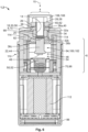
- Fig. 6
- shows a schematic sectional illustration of the electrical switching device according to the invention from
Figure 5 . - The schematic configuration of an
electrical switching device 1 according to the invention shall be explained with reference toFigures 1 to 6 . - As shown in
Figure 1 ,electrical switching device 1 according to the invention can comprise aconnection section 4 and aninner section 6. A fastening element 8 can be present onconnection section 4. Fastening element 8 optionally comprises aninsertion opening 14 which extends along a direction ofinsertion 15 through fastening element 8.Insertion opening 14 illustrated has a circular cross section and serves to receive anelectrical conductor 26 or a fixation element 28 ofelectrical conductor 26, respectively (seeFigure 5 ). Alternatively, this can also be a slot-shaped, triangular, quadrangular, pentagonal, hexagonal or polygonal insertion opening. - In the exemplary embodiment shown, fastening element 8 is configured as a screw-nut 10. Screw-nut 10 has in particular a hexagonal
outer shape 12 and aninternal thread 16 ininsertion opening 14. - Furthermore, an electrically conductive contacting element 18 can be disposed at
connection section 4, wherein contacting element 18 extends from fastening element 8 at least up to acontact point 20 of a current-carrying element 22 which is spaced from fastening element 8 and runs ininner section 6. - Contacting element 18 can be configured to be clamp-shaped. As shown in
Figure 1 , contacting element 18 can be formed in particular as a U-shaped clamp 30 having twolegs Spacing 34 oflegs - On at least one of the
legs 32a, contacting element 18 can comprise anopening 36a that is aligned withinsertion opening 14 in the direction ofinsertion 15. In the embodiment shown, alignedopening 36a is realized by abore 40 passing through acontact surface 38 of contacting element 18. - The
other leg 32b can likewise comprise anopening 36b that is aligned or not aligned withinsertion opening 14 in the direction ofinsertion 15.Contact point 20 can be disposed inopening 36b. As shown inFigure 1 , current-carrying element 22 can, in particular, be configured as a rivet head 44 and riveted to contacting element 18 atcontact point 20. Alternatively, current-carrying element 22 can also be implemented by a screw head (not shown). - A
contact member 48 can be located at anend 46 of current-carrying element 22 facing away fromcontact point 20.Contact member 48 can be arranged in particular opposite to a complementary switching mechanism element 50, for example, a contact bridge 52, and together form anelectrical switching mechanism 110. This arrangement results in aseparation point 54 at which an electrical circuit, into whichelectrical switching device 1 is integrated, can be closed or opened, respectively. - Contacting element 18 can be fabricated from a sheet metal material. Contacting element 18 is optionally a stamped and bent member 56. Alternatively, contacting element 18 can also be a cast or forged member.
- Fixation element 28 of
electrical conductor 26 can be inserted throughbore 40 of contact element 18 intoinsertion opening 14 of fastening element 8.Electrical conductor 26 can there be touchingcontact surface 38 of contacting element 18. This is shown inFigure 6 . - As can be seen in anticipation from
Figure 5 , a retaining screw 58 can be used as fixation element 28 forelectrical conductor 26. For this purpose,electrical conductor 26 can comprise, for example as shown, acable lug 60 with aneyelet 62, whereincable lug 60 is attached to oneend 64 ofelectrical conductor 26. - Retaining screw 58 comprises an
external thread 66 which is compatible withinternal thread 16 of fastening element 8 configured as a screw-nut 10 and can be used to establish areleasable screw connection 68. As an alternative to retaining screw 58, for example, a banana plug (not shown) can also be used as a fixation element 28 forelectrical conductor 26 and be inserted intoinsertion opening 14. The banana plug can correspondingly be attached as part ofcable lug 60 and instead ofeyelet 62 onend 64 ofelectrical conductor 26. - Fastening element 8 preferably has a greater mechanical strength than contacting element 18. In addition, contacting element 18 can be electrically conductive and preferably exhibit greater electrical conductivity than fastening element 8. Fastening element 8 is disposed in particular outside an intended
current path 24 ofelectrical switching device 1. - Fastening element 8 and contacting element 18 can be separate components that can be detached from one another. Alternatively, there can be a permanent connection, for example, a welded, soldered or adhesive bond, between fastening element 8 and contacting element 18.
- Moving on to
Figure 2 , it can be seen thatelectrical switching device 1 can also comprise ahousing 70, wherein the housing comprises at least onerecess 72 for receiving fastening element 8. In the embodiment shown, tworecesses 72 are provided, in each of which a fastening element 8 configured as a screw-nut 10 can be inserted, preferably removable in a direction opposite to the direction ofinsertion 15.Recesses 72 can have a shape that is complementary to fastening element 8. Due to fastening element 8 being configured as a screw-nut 10 with a hexagonalouter shape 12, recesses 72 have a hexagonalinner shape 74 that matches the hexagonalouter shape 12. This means thatrecesses 72 each consist of a lowered,hexagonal base surface 76 and sixside surfaces 78 each abutting against an edge ofbase surface 76. The spacing between two opposite side surfaces 78 corresponds to the width across flats of hexagonalouter shape 12. - Optionally,
recess 72 can have a lateral access 80 which runs perpendicular to the direction ofinsertion 15. This is indicated inFigure 2 for onerecess 72 by dashed lines. Access 80 can optionally connect bothrecesses 72 to one another. - As is also clear from
Figure 2 ,housing 70 can comprise at least one receivingslot 82. The at least one receivingslot 82 can have arectangular cross section 84 and extend perpendicular to the direction ofinsertion 15 throughhousing 70. In particular, the at least one receivingslot 82 can extend in the direction ofinsertion 15 overlapping with one ofrecesses 72 and fastening element 8 placed thereinto. In other words, the at least one receivingslot 82 is optionally arranged betweenconnection section 4 andinner section 6, more precisely between fastening element 8 and current-carrying element 22 (seeFigure 6 ). - Contacting element 18 configured as a clamp 30 can protrude with one
leg slot 82. Advantageously,leg 32b withopening 36b is introduced, plugged or pushed into the at least one receivingslot 82. This is shown inFigure 3 , according to which contacting element 18 configured as a clamp 30 covers fastening element 8 at least in sections with theother leg 32a towards the outside. Fastening element 8 can thus be secured or held in thecorresponding recess 72 by contacting element 18.Connection section 4, inparticular contact surface 38 of contacting element 18, is accessible from the outside, for example, for contacting throughelectrical conductor 26. -
Figure 3 illustrates thatconnection section 4 can be arranged on anelevated portion 86 ofhousing 70.Elevated portion 86 can be located in particular on an outer side 88 ofhousing 70, preferably on an upper side 90 ofhousing 70 pointing in a direction opposite to the direction ofinsertion 15. Furthermore, the at least onerecess 72 and the at least one receivingslot 82 can be formed intoelevated portion 86. -
Figure 4 shows a bottom view ofhousing 70, from which it can be seen that the at least one receivingslot 82 can be connected via anopening 36c to an interior 94 ofhousing 70.Opening 36c is advantageously aligned with opening 36b ofleg 32b whenleg 32b withopening 36b is inserted, plugged or pushed into the at least one receivingslot 82. In the embodiment shown, current-carrying element 22 configured as a rivet head 44 can protrude in part through opening 36c intoopening 36b and be riveted to contacting element 18.Contact point 20 can accordingly be arranged in the at least one receivingslot 82. This is shown, for example, inFigure 6 . As can also be seen inFigure 6 , contacting element 18 can connectconnection section 4 tointerior 94 ofhousing 70. -
Electrical switching device 1 shown by way of example as a contactor 2 inFigure 5 can comprise at least oneconnection section 4. At least twoconnection sections 4 are preferably provided in pairs onelectrical switching device 1, in particular onhousing 70 ofelectrical switching device 1. Furthermore,electrical switching device 1 can comprise a shell-shapedhousing cover 98 which can be connected tohousing 70 configured as a complement 96, so that a preferably gas-tight interior 100 is created in inside 102 ofelectrical switching device 1. - For each
connection section 4,electrical switching device 1 preferably comprises a power cable 104 which is fastened to and contacted on the associatedconnection section 4. This attachment can be effected as it has already been explained above forelectrical conductor 26.Connection sections 4 are preferably arranged on the same outer side 88 ofhousing 70 and separated from one another by a rib-shaped web 106 protruding fromhousing 70 in a direction opposite to direction ofinsertion 15. - In the embodiment shown, rib-shaped web 106 is shown as an end-to-end rib 108. To simplify the process of placing fastening element 8 into
recess 72, rib 108 can comprise a centrally arranged break (not shown). For reasons of electrical safety, it must there be ensured that the break is narrower than power cable 104 so that power cable 104 cannot pass through the break. - In interior 100 of
electrical switching device 1, current-carrying elements 22 in pairs can be part of anelectrical switching mechanism 110. For this purpose, a complementary switching mechanism element 50, for example, a contact bridge 52, is arranged disposed oppositerespective contact members 48 in interior 100 ofelectrical switching device 1. Contact bridge 52 is moved in accordance with incoming switching commands by way of anactuating coil 112 that is likewise located in interior 100 ofelectrical switching device 1. - It can be seen in the sectional illustration in
Figure 6 thatchambers 114 can be formed inhousing 70 perpendicular to the direction ofinsertion 15 next to receivingslot 82.Chambers 114 extend interior 100 ofelectrical switching device 1, so that interior 100 provides additional space for expanding arcs which arise betweencontact member 48 and contact bridge 52 during a separation process ofelectrical switching mechanism 110. - The electrical switching device shown as contactor 2 can be a DC contactor or an AC contactor. Alternatively, the present invention can also be used in relays or similar electrical switches.
-
- 1
- electrical switching device
- 2
- contactor
- 4
- connection section
- 6
- inner section
- 8
- fastening element
- 10
- screw-nut
- 12
- hexagonal outer shape
- 14
- insertion opening
- 15
- direction of insertion
- 16
- internal thread
- 18
- contacting element
- 20
- contact point
- 22
- current-carrying element
- 24
- current path
- 26
- electrical conductor
- 28
- fixation element
- 30
- clamp
- 32
- leg
- 34
- spacing
- 36a, 36b, 36c
- opening
- 38
- contact surface
- 40
- bore
- 44
- rivet head
- 46
- end
- 48
- contact member
- 50
- switching mechanism element
- 52
- contact bridge
- 54
- separation point
- 56
- stamped and bent member
- 58
- retaining screw
- 60
- cable lug
- 62
- eyelet
- 64
- end
- 66
- external thread
- 68
- screw connection
- 70
- housing
- 72
- recess
- 74
- hexagonal inner shape
- 76
- base surface
- 78
- side surface
- 80
- access
- 82
- reception slot
- 84
- cross section
- 86
- elevated portion
- 88
- outer side
- 90
- upper side
- 94
- interior
- 96
- complement
- 98
- housing cover
- 100
- interior
- 102
- inside
- 104
- power cable
- 106
- web
- 108
- rib
- 110
- switching mechanism
- 112
- actuation coil
- 114
- chamber
Claims (15)
- Electrical switching device (1) with a connection section (4) for fastening and contacting an electrical conductor (26), wherein a fastening element (8) for fastening said electrical conductor (26) and an electrically conductive contacting element (18), said contacting element (18) reaching from said fastening element (8) to a contact point (20) of a current-carrying element (22), said current-carrying element (22) being spaced from said fastening element (8) and extending in an inner section (6) of said electrical switching device (1), are present on said connection section (4), wherein said fastening element (8) exhibits a greater strength than said contacting element (18), and wherein said contacting element (18) is electrically conductive.
- Electrical switching device (1) according to claim 1, wherein said fastening element (8) comprises an insertion opening (14) for receiving said electrical conductor (26).
- Electrical switching device (1) according to claim 2, wherein said contacting element (18) comprises an opening (36) aligned with said insertion opening (14).
- Electrical switching device (1) according to one of the claims 1 to 3, wherein said electrical switching device (1) furthermore comprises a housing (70) with a recess (72) for receiving said fastening element (8).
- Electrical switching device (1) according to one of the claims 1 to 4, wherein said fastening element (8) is secured by said contacting element (18).
- Electrical switching device (1) according to one of the claims 1 to 5, wherein said contacting element (18) covers said fastening element (8) at least in sections.
- Electrical switching device (1) according to one of the claims 1 to 6, wherein said contacting element (18) is configured to be clamp-shaped.
- Electrical switching device (1) according to one of the claims 1 to 7, wherein said contacting element (18) protrudes at least in sections into a receiving slot (82).
- Electrical switching device (1) according to claim 8, wherein said receiving slot (82) is arranged between said connection section (4) and said inner section (6).
- Electrical switching device (1) according to claim 8 or 9, wherein said contact point (20) is arranged in said receiving slot (82).
- Electrical switching device (1) according to one of the claims 1 to 10, wherein said current-carrying element (22) is a screw head or rivet head (44) fastened to said contacting element (18).
- Electrical switching device (1) according to one of the claims 4 to 11, wherein said connection section (4) is arranged on an elevated portion (86) of said housing (70).
- Electrical switching device (1) according to claim 12, wherein said contacting element (18) is inserted at least in sections between said elevated portion (86) and the remainder of said switching device.
- Electrical switching device (1) according to one of the claims 1 to 13, wherein said electrical switching device (1) in said inner section (6) comprises an electrical switching mechanism (110) and wherein said current-carrying element (22) is part of said electrical switching mechanism (110).
- Electrical switching device (1) according to one of the claims 1 to 14 with a plurality of connection sections (4).
Applications Claiming Priority (1)
| Application Number | Priority Date | Filing Date | Title |
|---|---|---|---|
| DE102020203056.1A DE102020203056A1 (en) | 2020-03-10 | 2020-03-10 | Electrical switching device, in particular a contactor or a relay, with a contacting element and a fastening element |
Publications (2)
| Publication Number | Publication Date |
|---|---|
| EP3879552A1 EP3879552A1 (en) | 2021-09-15 |
| EP3879552B1 true EP3879552B1 (en) | 2024-07-31 |
Family
ID=74870646
Family Applications (1)
| Application Number | Title | Priority Date | Filing Date |
|---|---|---|---|
| EP21161652.9A Active EP3879552B1 (en) | 2020-03-10 | 2021-03-10 | Electrical switching device, in particular a contactor or a relay, with a contacting element and a fastening element |
Country Status (6)
| Country | Link |
|---|---|
| US (1) | US11742164B2 (en) |
| EP (1) | EP3879552B1 (en) |
| JP (1) | JP2021144932A (en) |
| KR (1) | KR20210114343A (en) |
| CN (1) | CN113380559A (en) |
| DE (1) | DE102020203056A1 (en) |
Citations (1)
| Publication number | Priority date | Publication date | Assignee | Title |
|---|---|---|---|---|
| US8427262B2 (en) * | 2008-12-03 | 2013-04-23 | Ls Industrial Systems Co., Ltd. | Electromagnetic contactor with abrasion preventing means |
Family Cites Families (24)
| Publication number | Priority date | Publication date | Assignee | Title |
|---|---|---|---|---|
| FR2562321B1 (en) * | 1984-03-28 | 1986-08-01 | Telemecanique Electrique | ELECTRICAL SWITCHING APPARATUS COMPRISING A GAS-TIGHT CONTACTS PROTECTION COVER |
| ES2035843T3 (en) * | 1987-11-25 | 1993-05-01 | Square D Company (Deutschland) Gmbh | CONTACTOR. |
| JPH0397848U (en) * | 1990-01-24 | 1991-10-09 | ||
| JPH06208823A (en) * | 1992-11-17 | 1994-07-26 | Fuji Electric Co Ltd | Electromagnetic contactor |
| US5631613A (en) * | 1994-11-22 | 1997-05-20 | Nippondenso Co., Ltd. | Magnet switch for engine starter |
| US5493085A (en) | 1995-02-17 | 1996-02-20 | Eaton Corporation | Spring clip assembly for electrical connections to flat stabs and switches incorporating the same |
| US5772479A (en) | 1996-05-10 | 1998-06-30 | Fleege; Dennis William | Circuit breaker with terminal nut retainer |
| DE10102127A1 (en) * | 2001-01-18 | 2002-07-25 | Magcode Ag | Arrangement for connecting electrical conductors, has fixing device for electrical conductors with pressure bridge extending along conductors, and actuating element for pressure bridge |
| TWI263384B (en) * | 2002-12-19 | 2006-10-01 | Fuji Electric Co Ltd | Terminal device for electrical equipment |
| KR200417351Y1 (en) | 2006-03-17 | 2006-05-26 | 엘에스산전 주식회사 | Terminal contact device of magnetic contactor |
| JP2008016281A (en) * | 2006-07-05 | 2008-01-24 | Denso Corp | magnetic switch |
| FR2931583A1 (en) | 2008-05-22 | 2009-11-27 | Schneider Electric Ind Sas | CONTACT DEVICE FOR RESISTIVE HIGH POWER SWITCH |
| JP4706742B2 (en) * | 2008-09-19 | 2011-06-22 | 富士電機機器制御株式会社 | Coil unit for magnetic contactor and method for assembling the same |
| JP5437949B2 (en) * | 2010-08-11 | 2014-03-12 | 富士電機機器制御株式会社 | Contact device and electromagnetic contactor using the same |
| KR101082263B1 (en) * | 2010-10-27 | 2011-11-09 | 엘에스산전 주식회사 | Connector for ring terminal connection |
| JP5864902B2 (en) | 2011-05-19 | 2016-02-17 | 富士電機機器制御株式会社 | Assembling method of arc extinguishing chamber of magnetic contactor |
| DE102011081855A1 (en) * | 2011-08-31 | 2013-02-28 | Siemens Aktiengesellschaft | Adapter for a clamping device |
| CN202712071U (en) * | 2012-06-01 | 2013-01-30 | Abb公司 | Switching device |
| JP5523594B2 (en) * | 2013-02-06 | 2014-06-18 | 三菱電機株式会社 | Switch |
| JP2016207473A (en) * | 2015-04-22 | 2016-12-08 | パナソニックIpマネジメント株式会社 | Switch structure and switch |
| KR20170009348A (en) * | 2015-07-16 | 2017-01-25 | 엘에스산전 주식회사 | Relay for electronic vehicle including permanent magnet and method of fabricating thereof |
| US20170093051A1 (en) * | 2015-09-25 | 2017-03-30 | Hamilton Sundstrand Corporation | Wire lug captivation system and method |
| DE102016110050B4 (en) * | 2016-05-31 | 2020-01-23 | Endress+Hauser SE+Co. KG | Plug connection for electrical contacting of a printed circuit board |
| FR3066642B1 (en) * | 2017-05-17 | 2020-09-04 | Schneider Electric Ind Sas | REMOVABLE ELEMENT FOR CUTTING AN ELECTRIC CURRENT AND ELECTRICAL CUTTING DEVICE FOR AN ELECTRIC CURRENT INCLUDING SUCH A REMOVABLE CUTTING ELEMENT |
-
2020
- 2020-03-10 DE DE102020203056.1A patent/DE102020203056A1/en active Pending
-
2021
- 2021-03-05 KR KR1020210029418A patent/KR20210114343A/en active Pending
- 2021-03-05 JP JP2021034948A patent/JP2021144932A/en active Pending
- 2021-03-08 CN CN202110249000.5A patent/CN113380559A/en active Pending
- 2021-03-10 US US17/197,492 patent/US11742164B2/en active Active
- 2021-03-10 EP EP21161652.9A patent/EP3879552B1/en active Active
Patent Citations (1)
| Publication number | Priority date | Publication date | Assignee | Title |
|---|---|---|---|---|
| US8427262B2 (en) * | 2008-12-03 | 2013-04-23 | Ls Industrial Systems Co., Ltd. | Electromagnetic contactor with abrasion preventing means |
Also Published As
| Publication number | Publication date |
|---|---|
| KR20210114343A (en) | 2021-09-23 |
| CN113380559A (en) | 2021-09-10 |
| EP3879552A1 (en) | 2021-09-15 |
| US20210287865A1 (en) | 2021-09-16 |
| JP2021144932A (en) | 2021-09-24 |
| US11742164B2 (en) | 2023-08-29 |
| DE102020203056A1 (en) | 2021-09-16 |
Similar Documents
| Publication | Publication Date | Title |
|---|---|---|
| KR200376471Y1 (en) | A Terminal Connecting Device of the Electronic Contactor | |
| CA2607348A1 (en) | Modular service switching device | |
| US20130307650A1 (en) | Switching device and accessory on the connecting side | |
| WO2010146525A1 (en) | Low cost clamp for connection of electric wires or cables on printed circuits | |
| EP2315313B1 (en) | Assembly for multiple connection in an electrical apparatus | |
| JPH10247538A (en) | Printed board or socket terminal for electric device | |
| EP3879552B1 (en) | Electrical switching device, in particular a contactor or a relay, with a contacting element and a fastening element | |
| US5559489A (en) | Fuse holder for an electric switch | |
| US3840717A (en) | Manually operated rotary switch and combination load contact-fuse clip therefor | |
| KR101048250B1 (en) | Fuse installation structure of vacuum switch | |
| EP3108494B1 (en) | Switching assembly and interconnect assembly therefor | |
| KR101912701B1 (en) | Power relay for a vehicle | |
| RU2742329C1 (en) | Attachment terminal | |
| US5903201A (en) | Relay for high breaking capacities | |
| US20080102714A1 (en) | Service switching device and connection terminal for a service switching device | |
| US8314670B2 (en) | Switching device | |
| US6884952B2 (en) | Contact finger for a high-power switchgear | |
| EP2462607B1 (en) | A switching device | |
| RU2297066C2 (en) | Electric power switch with connecting bus and arcing horn | |
| KR20200063518A (en) | One-touch combination type bus bar kit | |
| KR20100039052A (en) | box | |
| US20240186726A1 (en) | Electrical contact piece having an integrated stop and electrical contact device for at least one electrical pole having at least one such electrical contact piece | |
| US20240295343A1 (en) | Safety device for electrical appliances | |
| WO2018170905A1 (en) | Electrical equipment for use in electrical or hybrid vehicle | |
| US2832873A (en) | Support assemblies |
Legal Events
| Date | Code | Title | Description |
|---|---|---|---|
| PUAI | Public reference made under article 153(3) epc to a published international application that has entered the european phase |
Free format text: ORIGINAL CODE: 0009012 |
|
| STAA | Information on the status of an ep patent application or granted ep patent |
Free format text: STATUS: THE APPLICATION HAS BEEN PUBLISHED |
|
| AK | Designated contracting states |
Kind code of ref document: A1 Designated state(s): AL AT BE BG CH CY CZ DE DK EE ES FI FR GB GR HR HU IE IS IT LI LT LU LV MC MK MT NL NO PL PT RO RS SE SI SK SM TR |
|
| STAA | Information on the status of an ep patent application or granted ep patent |
Free format text: STATUS: REQUEST FOR EXAMINATION WAS MADE |
|
| 17P | Request for examination filed |
Effective date: 20220315 |
|
| RBV | Designated contracting states (corrected) |
Designated state(s): AL AT BE BG CH CY CZ DE DK EE ES FI FR GB GR HR HU IE IS IT LI LT LU LV MC MK MT NL NO PL PT RO RS SE SI SK SM TR |
|
| STAA | Information on the status of an ep patent application or granted ep patent |
Free format text: STATUS: EXAMINATION IS IN PROGRESS |
|
| 17Q | First examination report despatched |
Effective date: 20221123 |
|
| GRAP | Despatch of communication of intention to grant a patent |
Free format text: ORIGINAL CODE: EPIDOSNIGR1 |
|
| STAA | Information on the status of an ep patent application or granted ep patent |
Free format text: STATUS: GRANT OF PATENT IS INTENDED |
|
| INTG | Intention to grant announced |
Effective date: 20240328 |
|
| GRAS | Grant fee paid |
Free format text: ORIGINAL CODE: EPIDOSNIGR3 |
|
| GRAA | (expected) grant |
Free format text: ORIGINAL CODE: 0009210 |
|
| STAA | Information on the status of an ep patent application or granted ep patent |
Free format text: STATUS: THE PATENT HAS BEEN GRANTED |
|
| AK | Designated contracting states |
Kind code of ref document: B1 Designated state(s): AL AT BE BG CH CY CZ DE DK EE ES FI FR GB GR HR HU IE IS IT LI LT LU LV MC MK MT NL NO PL PT RO RS SE SI SK SM TR |
|
| REG | Reference to a national code |
Ref country code: CH Ref legal event code: EP Ref country code: GB Ref legal event code: FG4D |
|
| REG | Reference to a national code |
Ref country code: DE Ref legal event code: R096 Ref document number: 602021016326 Country of ref document: DE |
|
| REG | Reference to a national code |
Ref country code: IE Ref legal event code: FG4D |
|
| REG | Reference to a national code |
Ref country code: LT Ref legal event code: MG9D |
|
| REG | Reference to a national code |
Ref country code: NL Ref legal event code: MP Effective date: 20240731 |
|
| PG25 | Lapsed in a contracting state [announced via postgrant information from national office to epo] |
Ref country code: PT Free format text: LAPSE BECAUSE OF FAILURE TO SUBMIT A TRANSLATION OF THE DESCRIPTION OR TO PAY THE FEE WITHIN THE PRESCRIBED TIME-LIMIT Effective date: 20241202 |
|
| REG | Reference to a national code |
Ref country code: AT Ref legal event code: MK05 Ref document number: 1709297 Country of ref document: AT Kind code of ref document: T Effective date: 20240731 |
|
| PG25 | Lapsed in a contracting state [announced via postgrant information from national office to epo] |
Ref country code: PT Free format text: LAPSE BECAUSE OF FAILURE TO SUBMIT A TRANSLATION OF THE DESCRIPTION OR TO PAY THE FEE WITHIN THE PRESCRIBED TIME-LIMIT Effective date: 20241202 |
|
| PG25 | Lapsed in a contracting state [announced via postgrant information from national office to epo] |
Ref country code: NO Free format text: LAPSE BECAUSE OF FAILURE TO SUBMIT A TRANSLATION OF THE DESCRIPTION OR TO PAY THE FEE WITHIN THE PRESCRIBED TIME-LIMIT Effective date: 20241031 |
|
| PG25 | Lapsed in a contracting state [announced via postgrant information from national office to epo] |
Ref country code: NL Free format text: LAPSE BECAUSE OF FAILURE TO SUBMIT A TRANSLATION OF THE DESCRIPTION OR TO PAY THE FEE WITHIN THE PRESCRIBED TIME-LIMIT Effective date: 20240731 Ref country code: FI Free format text: LAPSE BECAUSE OF FAILURE TO SUBMIT A TRANSLATION OF THE DESCRIPTION OR TO PAY THE FEE WITHIN THE PRESCRIBED TIME-LIMIT Effective date: 20240731 Ref country code: GR Free format text: LAPSE BECAUSE OF FAILURE TO SUBMIT A TRANSLATION OF THE DESCRIPTION OR TO PAY THE FEE WITHIN THE PRESCRIBED TIME-LIMIT Effective date: 20241101 Ref country code: PL Free format text: LAPSE BECAUSE OF FAILURE TO SUBMIT A TRANSLATION OF THE DESCRIPTION OR TO PAY THE FEE WITHIN THE PRESCRIBED TIME-LIMIT Effective date: 20240731 |
|
| PG25 | Lapsed in a contracting state [announced via postgrant information from national office to epo] |
Ref country code: BG Free format text: LAPSE BECAUSE OF FAILURE TO SUBMIT A TRANSLATION OF THE DESCRIPTION OR TO PAY THE FEE WITHIN THE PRESCRIBED TIME-LIMIT Effective date: 20240731 |
|
| PG25 | Lapsed in a contracting state [announced via postgrant information from national office to epo] |
Ref country code: LV Free format text: LAPSE BECAUSE OF FAILURE TO SUBMIT A TRANSLATION OF THE DESCRIPTION OR TO PAY THE FEE WITHIN THE PRESCRIBED TIME-LIMIT Effective date: 20240731 |
|
| PG25 | Lapsed in a contracting state [announced via postgrant information from national office to epo] |
Ref country code: IS Free format text: LAPSE BECAUSE OF FAILURE TO SUBMIT A TRANSLATION OF THE DESCRIPTION OR TO PAY THE FEE WITHIN THE PRESCRIBED TIME-LIMIT Effective date: 20241130 Ref country code: AT Free format text: LAPSE BECAUSE OF FAILURE TO SUBMIT A TRANSLATION OF THE DESCRIPTION OR TO PAY THE FEE WITHIN THE PRESCRIBED TIME-LIMIT Effective date: 20240731 |
|
| PG25 | Lapsed in a contracting state [announced via postgrant information from national office to epo] |
Ref country code: HR Free format text: LAPSE BECAUSE OF FAILURE TO SUBMIT A TRANSLATION OF THE DESCRIPTION OR TO PAY THE FEE WITHIN THE PRESCRIBED TIME-LIMIT Effective date: 20240731 |
|
| PG25 | Lapsed in a contracting state [announced via postgrant information from national office to epo] |
Ref country code: ES Free format text: LAPSE BECAUSE OF FAILURE TO SUBMIT A TRANSLATION OF THE DESCRIPTION OR TO PAY THE FEE WITHIN THE PRESCRIBED TIME-LIMIT Effective date: 20240731 Ref country code: RS Free format text: LAPSE BECAUSE OF FAILURE TO SUBMIT A TRANSLATION OF THE DESCRIPTION OR TO PAY THE FEE WITHIN THE PRESCRIBED TIME-LIMIT Effective date: 20241031 |
|
| PG25 | Lapsed in a contracting state [announced via postgrant information from national office to epo] |
Ref country code: RS Free format text: LAPSE BECAUSE OF FAILURE TO SUBMIT A TRANSLATION OF THE DESCRIPTION OR TO PAY THE FEE WITHIN THE PRESCRIBED TIME-LIMIT Effective date: 20241031 Ref country code: PL Free format text: LAPSE BECAUSE OF FAILURE TO SUBMIT A TRANSLATION OF THE DESCRIPTION OR TO PAY THE FEE WITHIN THE PRESCRIBED TIME-LIMIT Effective date: 20240731 Ref country code: NO Free format text: LAPSE BECAUSE OF FAILURE TO SUBMIT A TRANSLATION OF THE DESCRIPTION OR TO PAY THE FEE WITHIN THE PRESCRIBED TIME-LIMIT Effective date: 20241031 Ref country code: NL Free format text: LAPSE BECAUSE OF FAILURE TO SUBMIT A TRANSLATION OF THE DESCRIPTION OR TO PAY THE FEE WITHIN THE PRESCRIBED TIME-LIMIT Effective date: 20240731 Ref country code: LV Free format text: LAPSE BECAUSE OF FAILURE TO SUBMIT A TRANSLATION OF THE DESCRIPTION OR TO PAY THE FEE WITHIN THE PRESCRIBED TIME-LIMIT Effective date: 20240731 Ref country code: IS Free format text: LAPSE BECAUSE OF FAILURE TO SUBMIT A TRANSLATION OF THE DESCRIPTION OR TO PAY THE FEE WITHIN THE PRESCRIBED TIME-LIMIT Effective date: 20241130 Ref country code: HR Free format text: LAPSE BECAUSE OF FAILURE TO SUBMIT A TRANSLATION OF THE DESCRIPTION OR TO PAY THE FEE WITHIN THE PRESCRIBED TIME-LIMIT Effective date: 20240731 Ref country code: GR Free format text: LAPSE BECAUSE OF FAILURE TO SUBMIT A TRANSLATION OF THE DESCRIPTION OR TO PAY THE FEE WITHIN THE PRESCRIBED TIME-LIMIT Effective date: 20241101 Ref country code: FI Free format text: LAPSE BECAUSE OF FAILURE TO SUBMIT A TRANSLATION OF THE DESCRIPTION OR TO PAY THE FEE WITHIN THE PRESCRIBED TIME-LIMIT Effective date: 20240731 Ref country code: ES Free format text: LAPSE BECAUSE OF FAILURE TO SUBMIT A TRANSLATION OF THE DESCRIPTION OR TO PAY THE FEE WITHIN THE PRESCRIBED TIME-LIMIT Effective date: 20240731 Ref country code: BG Free format text: LAPSE BECAUSE OF FAILURE TO SUBMIT A TRANSLATION OF THE DESCRIPTION OR TO PAY THE FEE WITHIN THE PRESCRIBED TIME-LIMIT Effective date: 20240731 Ref country code: AT Free format text: LAPSE BECAUSE OF FAILURE TO SUBMIT A TRANSLATION OF THE DESCRIPTION OR TO PAY THE FEE WITHIN THE PRESCRIBED TIME-LIMIT Effective date: 20240731 |
|
| PG25 | Lapsed in a contracting state [announced via postgrant information from national office to epo] |
Ref country code: SM Free format text: LAPSE BECAUSE OF FAILURE TO SUBMIT A TRANSLATION OF THE DESCRIPTION OR TO PAY THE FEE WITHIN THE PRESCRIBED TIME-LIMIT Effective date: 20240731 Ref country code: RO Free format text: LAPSE BECAUSE OF FAILURE TO SUBMIT A TRANSLATION OF THE DESCRIPTION OR TO PAY THE FEE WITHIN THE PRESCRIBED TIME-LIMIT Effective date: 20240731 Ref country code: DK Free format text: LAPSE BECAUSE OF FAILURE TO SUBMIT A TRANSLATION OF THE DESCRIPTION OR TO PAY THE FEE WITHIN THE PRESCRIBED TIME-LIMIT Effective date: 20240731 |
|
| PG25 | Lapsed in a contracting state [announced via postgrant information from national office to epo] |
Ref country code: EE Free format text: LAPSE BECAUSE OF FAILURE TO SUBMIT A TRANSLATION OF THE DESCRIPTION OR TO PAY THE FEE WITHIN THE PRESCRIBED TIME-LIMIT Effective date: 20240731 |
|
| PG25 | Lapsed in a contracting state [announced via postgrant information from national office to epo] |
Ref country code: CZ Free format text: LAPSE BECAUSE OF FAILURE TO SUBMIT A TRANSLATION OF THE DESCRIPTION OR TO PAY THE FEE WITHIN THE PRESCRIBED TIME-LIMIT Effective date: 20240731 |
|
| PG25 | Lapsed in a contracting state [announced via postgrant information from national office to epo] |
Ref country code: SK Free format text: LAPSE BECAUSE OF FAILURE TO SUBMIT A TRANSLATION OF THE DESCRIPTION OR TO PAY THE FEE WITHIN THE PRESCRIBED TIME-LIMIT Effective date: 20240731 |
|
| REG | Reference to a national code |
Ref country code: DE Ref legal event code: R097 Ref document number: 602021016326 Country of ref document: DE |
|
| PLBE | No opposition filed within time limit |
Free format text: ORIGINAL CODE: 0009261 |
|
| STAA | Information on the status of an ep patent application or granted ep patent |
Free format text: STATUS: NO OPPOSITION FILED WITHIN TIME LIMIT |
|
| 26N | No opposition filed |
Effective date: 20250501 |
|
| PG25 | Lapsed in a contracting state [announced via postgrant information from national office to epo] |
Ref country code: SE Free format text: LAPSE BECAUSE OF FAILURE TO SUBMIT A TRANSLATION OF THE DESCRIPTION OR TO PAY THE FEE WITHIN THE PRESCRIBED TIME-LIMIT Effective date: 20240731 |
|
| PG25 | Lapsed in a contracting state [announced via postgrant information from national office to epo] |
Ref country code: MC Free format text: LAPSE BECAUSE OF FAILURE TO SUBMIT A TRANSLATION OF THE DESCRIPTION OR TO PAY THE FEE WITHIN THE PRESCRIBED TIME-LIMIT Effective date: 20240731 |
|
| REG | Reference to a national code |
Ref country code: CH Ref legal event code: H13 Free format text: ST27 STATUS EVENT CODE: U-0-0-H10-H13 (AS PROVIDED BY THE NATIONAL OFFICE) Effective date: 20251023 |
|
| PG25 | Lapsed in a contracting state [announced via postgrant information from national office to epo] |
Ref country code: LU Free format text: LAPSE BECAUSE OF NON-PAYMENT OF DUE FEES Effective date: 20250310 |
|
| GBPC | Gb: european patent ceased through non-payment of renewal fee |
Effective date: 20250310 |
|
| REG | Reference to a national code |
Ref country code: BE Ref legal event code: MM Effective date: 20250331 |
|
| PG25 | Lapsed in a contracting state [announced via postgrant information from national office to epo] |
Ref country code: GB Free format text: LAPSE BECAUSE OF NON-PAYMENT OF DUE FEES Effective date: 20250310 |
|
| PGFP | Annual fee paid to national office [announced via postgrant information from national office to epo] |
Ref country code: FR Payment date: 20251231 Year of fee payment: 6 |
|
| PG25 | Lapsed in a contracting state [announced via postgrant information from national office to epo] |
Ref country code: BE Free format text: LAPSE BECAUSE OF NON-PAYMENT OF DUE FEES Effective date: 20250331 |
|
| PG25 | Lapsed in a contracting state [announced via postgrant information from national office to epo] |
Ref country code: CH Free format text: LAPSE BECAUSE OF NON-PAYMENT OF DUE FEES Effective date: 20250331 |
|
| PG25 | Lapsed in a contracting state [announced via postgrant information from national office to epo] |
Ref country code: IE Free format text: LAPSE BECAUSE OF NON-PAYMENT OF DUE FEES Effective date: 20250310 |
|
| PGFP | Annual fee paid to national office [announced via postgrant information from national office to epo] |
Ref country code: DE Payment date: 20260102 Year of fee payment: 6 |
|
| PGFP | Annual fee paid to national office [announced via postgrant information from national office to epo] |
Ref country code: IT Payment date: 20260220 Year of fee payment: 6 |