EP3879471A1 - Wrist terminal, work time management method, and storage medium - Google Patents
Wrist terminal, work time management method, and storage medium Download PDFInfo
- Publication number
- EP3879471A1 EP3879471A1 EP21160712.2A EP21160712A EP3879471A1 EP 3879471 A1 EP3879471 A1 EP 3879471A1 EP 21160712 A EP21160712 A EP 21160712A EP 3879471 A1 EP3879471 A1 EP 3879471A1
- Authority
- EP
- European Patent Office
- Prior art keywords
- work
- beacon
- work status
- information
- wrist terminal
- Prior art date
- Legal status (The legal status is an assumption and is not a legal conclusion. Google has not performed a legal analysis and makes no representation as to the accuracy of the status listed.)
- Withdrawn
Links
Images




Classifications
-
- G—PHYSICS
- G06—COMPUTING OR CALCULATING; COUNTING
- G06Q—INFORMATION AND COMMUNICATION TECHNOLOGY [ICT] SPECIALLY ADAPTED FOR ADMINISTRATIVE, COMMERCIAL, FINANCIAL, MANAGERIAL OR SUPERVISORY PURPOSES; SYSTEMS OR METHODS SPECIALLY ADAPTED FOR ADMINISTRATIVE, COMMERCIAL, FINANCIAL, MANAGERIAL OR SUPERVISORY PURPOSES, NOT OTHERWISE PROVIDED FOR
- G06Q10/00—Administration; Management
- G06Q10/06—Resources, workflows, human or project management; Enterprise or organisation planning; Enterprise or organisation modelling
-
- G—PHYSICS
- G06—COMPUTING OR CALCULATING; COUNTING
- G06Q—INFORMATION AND COMMUNICATION TECHNOLOGY [ICT] SPECIALLY ADAPTED FOR ADMINISTRATIVE, COMMERCIAL, FINANCIAL, MANAGERIAL OR SUPERVISORY PURPOSES; SYSTEMS OR METHODS SPECIALLY ADAPTED FOR ADMINISTRATIVE, COMMERCIAL, FINANCIAL, MANAGERIAL OR SUPERVISORY PURPOSES, NOT OTHERWISE PROVIDED FOR
- G06Q10/00—Administration; Management
- G06Q10/10—Office automation; Time management
- G06Q10/109—Time management, e.g. calendars, reminders, meetings or time accounting
- G06Q10/1091—Recording time for administrative or management purposes
-
- G—PHYSICS
- G06—COMPUTING OR CALCULATING; COUNTING
- G06F—ELECTRIC DIGITAL DATA PROCESSING
- G06F1/00—Details not covered by groups G06F3/00 - G06F13/00 and G06F21/00
- G06F1/16—Constructional details or arrangements
- G06F1/1613—Constructional details or arrangements for portable computers
- G06F1/163—Wearable computers, e.g. on a belt
-
- G—PHYSICS
- G06—COMPUTING OR CALCULATING; COUNTING
- G06Q—INFORMATION AND COMMUNICATION TECHNOLOGY [ICT] SPECIALLY ADAPTED FOR ADMINISTRATIVE, COMMERCIAL, FINANCIAL, MANAGERIAL OR SUPERVISORY PURPOSES; SYSTEMS OR METHODS SPECIALLY ADAPTED FOR ADMINISTRATIVE, COMMERCIAL, FINANCIAL, MANAGERIAL OR SUPERVISORY PURPOSES, NOT OTHERWISE PROVIDED FOR
- G06Q10/00—Administration; Management
- G06Q10/06—Resources, workflows, human or project management; Enterprise or organisation planning; Enterprise or organisation modelling
- G06Q10/063—Operations research, analysis or management
- G06Q10/0631—Resource planning, allocation, distributing or scheduling for enterprises or organisations
- G06Q10/06311—Scheduling, planning or task assignment for a person or group
- G06Q10/063114—Status monitoring or status determination for a person or group
-
- G—PHYSICS
- G07—CHECKING-DEVICES
- G07C—TIME OR ATTENDANCE REGISTERS; REGISTERING OR INDICATING THE WORKING OF MACHINES; GENERATING RANDOM NUMBERS; VOTING OR LOTTERY APPARATUS; ARRANGEMENTS, SYSTEMS OR APPARATUS FOR CHECKING NOT PROVIDED FOR ELSEWHERE
- G07C1/00—Registering, indicating or recording the time of events or elapsed time, e.g. time-recorders for work people
- G07C1/10—Registering, indicating or recording the time of events or elapsed time, e.g. time-recorders for work people together with the recording, indicating or registering of other data, e.g. of signs of identity
Definitions
- the present disclosure relates to a wrist terminal, a work time management method, and a storage medium.
- JP2019-102855A discloses a maintenance management system.
- a beacon is set in a building as a target of maintenance.
- a mobile terminal carried by the worker receives beacon information from the beacon and sends a building ID included in the beacon information to a monitoring device, thereby notifying the start of maintenance work in the building.
- JP2019-102855A when ending the work in the building, the worker has to perform an input operation with an operation receiver of the mobile terminal to notify that the maintenance ends. This requires time and effort.
- a wrist terminal including: a communicator that receives a beacon ID transmitted from a beacon transmitter installed in a workplace; a timer that obtains date-and-time information on a date and time at which the communicator receives the beacon ID; and at least one processor that performs: a determining process to determine whether a work status in the workplace is a work start or a work end, based on a state of the wrist terminal when the communicator receives the beacon ID; and a recording process to record, in a storage, log information that includes the date-and-time information obtained by the timer and work status information on the work status determined in the determining process, the date-and-time information and the work status information being associated with each other.
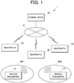
- FIG.1 shows components of a work time management system 1 in this embodiment.
- the work time management system 1 is a system that measures work time of a first step and second step in a specific work.
- the work time management system 1 includes: beacon transmitters 10 that are installed in a first workplace WP1 and a second workplace WP2; smartwatches 20 worn by workers; and a terminal device 30.
- the first workplace WP1 the first step is performed.
- the second workplace WP2 the second step is performed.
- the smartwatches 20 are prepared as many as the number of workers. The number of smartwatches 20 is not limited to a specific number.
- FIG.2 shows how the beacon transmitter 10 is installed in each of the workplaces WP1, WP2.
- the beacon transmitter 10 is installed on the wall of each of the workplaces WP1, WP2, for example.
- a sheet P1 is attached on the left wall of the beacon transmitter 10.
- P1 notifies the worker the position to be touched with the smartwatch 20 in starting work in the workplace.
- a sheet P2 is attached on the right wall of the beacon transmitter 10.
- P2 notifies the worker the position to be touched with the smartwatch 20 in ending work in the workplace.
- the beacon transmitter 10 be placed approximately as high as the worker's chest.
- the information on the sheet P1 may be written on the left-side surface of the beacon transmitter 10, instead of using the sheet P1.
- the information on the sheet P2 may be written on the right side surface of the beacon transmitter 10, instead of using the sheet P2.
- FIG.3A shows how the worker actually touches the beacon transmitter 10 with the smartwatch 20 when starting work in each workplace WP1/WP2.
- the worker wears the smartwatch 20 on his/her left wrist such that a display 25 of the smartwatch 20 is located at the back of the wrist.
- the worker when starting work in each workplace WP1/WP2, the worker refers to the information on the sheet P1 and brings the smartwatch 20, which is worn on the back of the left wrist, closer to the left-side surface of the beacon transmitter 10 from the left of the beacon transmitter 10, to touch the beacon transmitter 10.
- the worker touches the left side surface of the beacon transmitter 10 with the smartwatch 20 such that the top in the top-bottom direction of the display 25 of the smartwatch 20 faces upwards.
- FIG.3B shows how the worker actually touches the beacon transmitter 10 with the smartwatch 20 when ending work in each workplace WP1/WP2.
- the worker when ending work in each workplace WP1/WP2, the worker refers to the information on the sheet P2 and brings the smartwatch 20, which is worn on the back of the left wrist, closer to the right side surface of the beacon transmitter 10, to touch the beacon transmitter 10.
- the worker touches the right side surface of the beacon transmitter 10 with the smartwatch 20 such that the top in the top-bottom direction of the display 25 of the smartwatch 20 faces downwards.
- the beacon transmitter 10 transmits beacon information at predetermined time intervals over a communication method, such as Bluetooth (registered trademark) Low Energy (BLE).
- the beacon information includes a predetermined beacon ID.
- the beacon ID is identification information to identify the beacon transmitter 10.
- the workplace WP1/WP2 can be identified according to the beacon ID transmitted by the beacon transmitter 10, which is installed in the workplace WP1/WP2.
- the strength of signals transmitted by the beacon transmitter 10 is set such that the beacon transmitter 10 has the communication range of several centimeters to several tens of centimeters, for example.
- FIG.4 is a block diagram of functional components of the smartwatch 20.
- the smartwatch 20 includes: a central processing unit (CPU) 21, a random access memory (RAM) 22, a storage 23, an operation receiver 24, the display 25, a communicator 26, a beacon receiver 27, a timer 28, and a sensor 29. These components are connected via a bus B.
- the CPU 21 (obtaining unit, determining unit, recording unit, receiving unit) is a processor that controls the components of the smartwatch 20.
- the CPU 21 reads a program stored in the storage 23, loads the program into the RAM 22, and executes the program to perform various arithmetic processes.
- the RAM 22 provides the CPU 21 with a working memory space and stores temporary data.
- the RAM 22 may include a non-volatile memory.
- the storage 23 includes a storage device, such as a flash memory on which data can be written and from which data can be read.
- the storage 23 stores files including various programs, data, and so forth.
- the data to be stored in the storage 23 includes a posture correspondence table 231 and a work status record table 232.
- FIG.5 is an example of contents of the posture correspondence table 231.
- the posture correspondence table 231 is a table to determine the work status according to the posture of the smartwatch 20.
- information items on the posture of the smartwatch 20 are associated with information items on the work status. More specifically, an information item “upwards (opposite to direction of gravity)" is associated with an information item "work start”. Further, an information item “downwards (direction of gravity)” is associated with an information item "work end”.
- the work status is determined as work start.
- the work status is determined as work end.
- the information item on the work status "work start” corresponds to the information item on the posture of the smartwatch 20 "upwards (opposite to direction of gravity)".
- the information item on the work status "work end” corresponds to the information item on the posture of the smartwatch 20 "downwards (direction of gravity)", as an example.
- the correspondences between the information items on the posture of the smartwatch 20 and the information items on the work status may be changed as desired.
- the information items on the posture of the smartwatch 20 are not limited to above-described "upwards (opposite to direction of gravity)” and “downwards (direction of gravity)”.
- the information items on the work status are also not limited to the above-described "work start” and "work end”.
- the information items on the work status may be "work stop (e.g., start taking a rest)” and "work start (e.g., end the rest)".
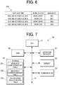
- FIG.6 is an example of contents of the work status record table 232.
- the work status record table 232 (storage) is a table to record the work statuses in the first and second workplaces WP1, WP2. As shown in FIG.6 , the work status record table 232 records information items on (i) a date and time at which a beacon ID is received, (ii) the work status (work start/work end) at the date and time, and (iii) the received beacon ID. The information items on (i) to (iii) are associated with each other.
- the operation receiver 24 includes a push-button switch(es) and a touch sensor provided on the display 25.
- the operation receiver 24 receives input operations by a user, converts the contents of the input operations into electric signals, and outputs the electric signals to the CPU 21.
- the display 25 includes a liquid crystal display (LCD) and performs display in accordance with display control signals from the CPU 21.
- the touch sensor is provided on the display screen of the display 25.
- the display 25 functions as a touchscreen that displays operations.
- the communicator 26 wirelessly connects to a communication network N ( FIG.1 ), for example.
- the communicator 26 communicates with external devices connected to the communication network N.
- the beacon receiver 27 communicates with the beacon transmitter 10 wirelessly at close range over the BLE.
- the beacon receiver 27 receives beacon information transmitted from the beacon transmitter 10 and outputs the received information to the CPU 21.
- the timer 28 includes, for example, a timekeeper and a timer circuit.
- the timer 28 measures the current date and time and outputs date-and-time information on the date and time to the CPU 21.
- the sensor 29 includes a three-axis acceleration sensor, for example.
- the sensor 29 outputs acceleration data measured by the three-axis acceleration sensor to the CPU 21.
- FIG.7 is a block diagram of functional components of the terminal device 30.
- the terminal device 30 (information processing device) includes: a CPU 31, a RAM 32, a storage 33, an operation receiver 34, a display 35, and a communicator 36. These components are connected via a bus B. Examples of the terminal device 30 include a laptop personal computer (PC) and a desktop PC.
- PC personal computer
- the CPU 31 (log information obtaining unit, calculating unit) is a processor that controls the components of the terminal device 30.
- the CPU 21 reads a program stored in the storage 33, loads the program into the RAM 32, and executes the program to perform various arithmetic processes.
- the RAM 32 provides the CPU 31 with a working memory space and stores temporary data.
- the RAM 32 may include a non-volatile memory.
- the storage 33 includes a storage device, such as a hard disk drive (HDD), a solid state drive (SSD), or a flash memory on which data can be written and from which data can be read.
- the storage 33 stores files including various programs and data.
- the data stored in the storage 33 includes a worker ID correspondence table 331, a beacon ID correspondence table 332, and a calculation result table 333.
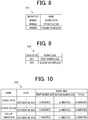
- FIG.8 is an example of contents of the worker ID correspondence table 331.
- the worker ID correspondence table 331 is a table to identify names of workers according to worker IDs. As shown in FIG.8 , the worker ID correspondence table 331 includes information items on the worker ID and the name of worker. Information items on the worker ID (e.g., "W0001") are recorded in association with information items on the name of worker (e.g., "Ichiro Sato").
- FIG.9 is an example of contents of the beacon ID correspondence table 332.
- the beacon ID correspondence table 332 is a table to identify workplaces according to beacon IDs. As shown in FIG.9 , the beacon ID correspondence table 332 includes information items on the beacon ID and on the workplace. The information item on the beacon ID "001" is associated with the information item on the workplace "first workplace”. Further, the information item on the beacon ID "002" is associated with the information item on the workplace "second workplace”.
- FIG.10 is an example of contents of the calculation result table 333.
- the calculation result table 333 is a table to record work times (calculation result) spent for specific works. As shown in FIG.10 , in the calculation result table 333, each worker is recorded in association with the date on which the worker performed a specific work and the work times.
- the work times include the work time in the workplace WP1, the work time in the workplace WP2, and the total of these work times.
- the operation receiver 34 includes a key input receiver, such as a keyboard, and a pointing device, such as a mouse.
- the operation receiver 34 receives inputs with key operation and inputs with position change operation by a user (supervisor who supervises the workers) and outputs the information on the operation to the CPU 31. Based on the information sent from the operation receiver 34, the CPU 31 receives the input operation by the user.
- the display 35 includes an LCD, for example and performs display in accordance with display control signals from the CPU 31.
- the communicator 36 wirelessly connects to the communication network N ( FIG.1 ), for example.
- the communicator 26 communicates with external devices connected to the communication network N.
- FIG.11 is a flowchart of a control procedure of the log information recording process that is performed by the smartwatch 20.
- the CPU 21 of the smartwatch 20 determines whether or not the beacon receiver 27 has received a beacon ID (beacon information) from the beacon transmitter 10 installed in the first workplace WP1 or the second workplace WP2 (Step S1).
- a beacon ID beacon information
- Step S1 When determining that the beacon receiver 27 has not received a beacon ID from the beacon transmitter 10 installed in the first workplace WP1 or the second workplace WP2 (Step S1: NO), the CPU 21 repeats Step S1 until receiving a beacon ID.
- Step S2 When determining that the beacon receiver 27 has received a beacon ID from the beacon transmitter 10 installed in the first workplace WP1 or the second workplace WP2 (Step S1: YES), the CPU 21 obtains date-and-time information at the time of receiving the beacon ID (Step S2).
- the CPU 21 derives the posture of the smartwatch 20 at the time of receiving the beacon ID (Step S3). More specifically, the CPU 21 obtains, from the sensor 29, acceleration data at the time of receiving the beacon ID. Based on the acceleration data, the CPU 21 derives the direction to which the top in the top-bottom direction of the display 25 of the smartwatch 20 faces (Step S3).
- the CPU 21 refers to the posture correspondence table 231 and determines whether or not the work status is determined based on the direction derived in Step S3, in which the top in the top-bottom direction of the display 25 of the smartwatch 20 faces (Step S4). For example, when the top in the top-bottom direction of the display 25 of the smartwatch 20 faces upwards in Step S3 as shown in FIG.3A (opposite to direction of gravity), the CPU 21 refers to the posture correspondence table 231 and determines that the work status is work start. When the top in the top-bottom direction of the display 25 of the smartwatch 20 faces downwards in Step S3 as shown in FIG.3B , the CPU 21 refers to the posture correspondence table 231 and determines that the work status is work end.
- Step S4 When determining that the work status is determined (Step S4: YES), the CPU 21 records log information in the work status record table 232 (Step S5).
- the log information includes: the beacon ID (e.g., "001") received in Step S1; the date-and-time information (e.g., 09:53 on October 29, 2019) obtained in Step S2; and the work status information on the work status determined in Step S4 (e.g., "work start").
- Step S4 When determining that the work status is not determined (Step S4: NO), the CPU 21 causes the display 25 to display a notification, such as sentences of "work status cannot be determined", as well as outputting beep sounds or generating vibrations.
- the CPU 21 also receives an input operation of inputting work status information ("work start” or "work end") with the operation receiver 24 (Step S6).
- the CPU 21 then records in the work status record table 232 the log information, which includes the beacon ID received in Step S1, the date-and-time information obtained in Step S2, and the work status information received in Step S6 (Step S5).
- Step S7 the CPU 21 performs a wait process for five seconds.
- the five-second wait process is performed to avoid duplicately receiving the beacon ID, which is continuously transmitted by the beacon transmitter 10.
- the CPU 21 determines whether or not an operation of work end has been made with the operation receiver 24 (Step S8).
- the operation of work end notifies that the work in the first workplace WP1 or the second workplace WP2 ends.
- Step S8 NO
- the CPU 21 returns to Step S1 and repeats the process of Step S1 and thereafter.
- Step S8 When determining that an operation of work end has been made (Step S8: YES), the CPU 21 associates the log information recorded in Step S5 with the worker ID for identifying the worker who wears the smartwatch 20, and sends the log information to the terminal device 30 (Step S9) . The CPU 21 then ends the log information recording process.
- FIG.12 is a flowchart of a control procedure of a work time calculating process that is performed by the terminal device 30.
- the CPU 31 of the terminal device 30 determines whether or not the log information has been received from the smartwatch 20 (Step 11).
- Step 11: NO When determining that the log information has not been received from the smartwatch 20 (Step 11: NO), the CPU 31 repeats Step S11 until receiving the log information.
- the CPU 31 calculates work times based on the log information (Step S12) .
- the CPU 31 receives four pieces of log information shown in FIG.6 .
- the CPU 31 extracts a piece of log information that includes (i) the same beacon ID, (ii) the work status information of "work end”, and (iii) the date-and-time information of the date and time immediately after "09:53 on October 29, 2019".
- the CPU 31 extracts the second log information that includes (i) the beacon ID of "001", (ii) the work status information of "work end”, and (iii) the date-and-time information of "10:05 on October 29, 2019".
- the CPU 31 calculates the difference in date and time between these two pieces of log information as a work time. Herein, the difference is 12 minutes.
- the CPU 31 also refers to the beacon ID correspondence table 332 and identifies the beacon ID "001" as "first workplace".
- the CPU 31 extracts a piece of log information that includes (i) the same beacon ID, (ii) the work status information of "work end”, and (iii) the date-and-time information of the date and time immediately after "10:15 on October 29, 2019". That is, the CPU 31 extracts the fourth log information that includes (i) the beacon ID of "002", (ii) the work status information of "work end”, and (iii) the date-and-time information of "10:37 on October 29, 2019". The CPU 31 calculates the difference in date and time between these two pieces of log information as a work time. Herein, the difference is 22 minutes.
- the CPU 31 also refers to the beacon ID correspondence table 332 and identifies the beacon ID "002" as "second workplace”.
- the CPU 31 identifies the worker, based on the worker ID associated with the log information received in Step S11 (Step S13). For example, when the worker ID associated with the log information is "W0001", the CPU 31 refers to the worker ID correspondence table 331 and identifies the worker ID "W0001" as the worker "Ichiro Sato".
- the CPU 31 records the work times of the worker who has been identified in Step S13 in the calculation result table 333 (Step S14). More specifically, assume that the CPU 31 identifies "Ichiro Sato" based on the worker ID and calculates the work time in the first workplace WP1 as 12 minutes and the work time in the second workplace WP2 as 22 minutes, as described above. The CPU 31 records (i) the information item on the date "October 29, 2019", (ii) the information item on the first workplace "12 minutes”, (iii) the information item on the second workplace "22 minutes”, and (iv) the total of the work times in the first and second workplaces "34 minutes".
- the information items on (i) to (iv) are associated with each other and recorded in their respective sections corresponding to "Ichiro Sato" in the calculation result table 333.
- the information item on the date is the date indicated by the date-and-time information in the log information received from the smartwatch 20.
- the information item on the total is the total of the corresponding information items of the first and second workplaces.
- the CPU 31 then returns to Step S11 and repeats the process of Step S11 and thereafter.
- the smartwatch 20 in the embodiment receives a beacon ID transmitted from the beacon transmitter 10 installed in each of the workplaces WP1, WP2, and obtains date-and-time information on the date and time at which the beacon transmitter 27 receives the beacon ID.
- the smartwatch 20 determines whether a work status in the workplace WP1/WP2 is work start or work end, based on the state of the smartwatch 20 when the beacon transmitter 27 receives the beacon ID.
- the smartwatch 20 then records, in the work status record table 232 in the storage 23, log information that includes the date-and-time information and work status information on the determined work status, the date-and-time information and the work status information being associated with each other.
- the smartwatch 20 can record the date and time of the work start and the work end. This allows the worker to notify the work start and work end easily and smoothly.
- the smartwatch 20 in the embodiment determines whether the work status in the workplace WP1/WP2 is work start or work end, based on the posture of the smartwatch 20 when the beacon receiver 27 receives the beacon ID.
- the smartwatch 20 can record the date and time of the work start and the work end. This allows the worker to notify the work start and work end further easily and smoothly.
- the smartwatch 20 in the embodiment determines that the work status in the workplace WP1/WP2 is the work start when the top in the top-bottom direction of the display 25 faces upwards when the beacon receiver 27 receives the beacon ID.
- the smartwatch 20 determines that the work status in the workplace WP1/WP2 is the work end when the top of the display 25 faces downwards when the beacon receiver 27 receives the beacon ID.
- the worker can touch the beacon transmitter 10 with the smartwatch 20 such that the top in the top-bottom direction of the display 25 faces upwards, while checking the current time on the display 25.
- the worker may have to touch the beacon transmitter 10 with the smartwatch 20 immediately without checking the current time on the display 25.
- the worker can touch the beacon transmitter 10 with the smartwatch 20 in a natural manner such that the top in the top-bottom direction of the display 25 faces downwards. This allows the worker to notify the work start and work end further smoothly.
- the smartwatch 20 in the embodiment receives an input operation of inputting the work status information.
- the smartwatch 20 associates the received work status information with the corresponding date-and-time information and stores the associated information in the work status record table 232 in the storage 23 as the log information.
- the smartwatch 20 receives operation of inputting the work status.
- the smartwatch 20 thus makes sure to record the date and time of the work start and work end. This allows the worker to notify the work start and work end appropriately.
- the work time management system 1 in the embodiment includes beacon transmitters 10 installed in the workplaces WP1, WP2 and a smartwatch(es) 20.
- the smartwatch 20 receives a beacon ID transmitted from the beacon transmitter 10 installed in each of the workplaces WP1, WP2, and obtains date-and-time information on the date and time at which the beacon transmitter 27 receives the beacon ID.
- the smartwatch 20 determines whether the work status in the workplace WP1/WP2 is work start or work end, based on the state of the smartwatch 20 when the beacon transmitter 27 receives the beacon ID.
- the smartwatch 20 then records, in the work status record table 232 in the storage 23, log information that includes the date-and-time information and work status information on the determined work status, the date-and-time information and the work status information being associated with each other.
- the workplaces WP1, WP2 do not need a beacon transmitter to record date and time of the work start and work end. This can reduce spaces and costs.
- the above embodiment is an example of the wrist terminal and the work time management system according to the present invention, and is not intended to limit the present invention.
- the smartwatch 20 determines whether the work status in the workplace WP1/WP2 is work start or work end, based on the posture of the smartwatch 20 at the time of receiving the beacon ID.
- the smartwatch 20 may determine whether the work status in workplace WP1/WP2 is work start or work end, based on the moving speed of the smartwatch 20 at the time of receiving the beacon ID, namely at the time when the worker brings the smartwatch 20 towards the beacon transmitter 10.
- the terminal device 30 calculates the work times in the respective workplaces WP1, WP2, based on the log information recorded by the smartwatch 20.
- the smartwatch 20 itself may be configured to calculate the work times in the workplaces WP1, WP2.
- the beacon transmitters 10 are installed in the workplaces WP1, WP2.
- transmitter devices 40 each of which includes a near field communication (NFC) unit 40A may be installed in the workplaces WP1, WP2, as shown in a work time management system 1A in FIG.13 .
- the NFC unit 40A is capable of wirelessly communicating with the smartwatch 20 at close range.
- the terminal device 30A receives, from the smartwatch 20, (i) state information on the state of the smartwatch 20 when the smartwatch 20 communicates with the NFC unit 40A (e.g., posture information of the smartwatch 20) and (ii) the terminal ID (worker ID) for identifying the smartwatch 20, via the transmitter device 40 with the NFC unit 40A.
- the terminal device 30A also obtains date-and-time information at the time of receiving the state information.
- the terminal device 30A determines whether the work status in the workplace WP1/WP2 is work start or work end.
- the terminal device 30A then associates work status information on the determined work status with the terminal ID (worker ID) and records the associated information as log information in a storage (not illustrated) of the terminal device 30A.
- the smartwatch 20 is made to be in different states (e.g., different postures) for different work statuses when wirelessly communicating at close range with the transmitter device 40 installed in each of the workplaces WP1, WP2, and the terminal device 30 records the date and time of work start and work end. This allows the worker to notify the work start and the work end smoothly and easily.
- the NFC unit 40A may be integrated with the transmitter device 40 or may be externally attached to the transmitter device 40.
Landscapes
- Business, Economics & Management (AREA)
- Engineering & Computer Science (AREA)
- Human Resources & Organizations (AREA)
- Strategic Management (AREA)
- Entrepreneurship & Innovation (AREA)
- Physics & Mathematics (AREA)
- General Physics & Mathematics (AREA)
- Theoretical Computer Science (AREA)
- Economics (AREA)
- Tourism & Hospitality (AREA)
- General Business, Economics & Management (AREA)
- Educational Administration (AREA)
- Quality & Reliability (AREA)
- Operations Research (AREA)
- Marketing (AREA)
- Computer Hardware Design (AREA)
- Game Theory and Decision Science (AREA)
- Development Economics (AREA)
- Human Computer Interaction (AREA)
- General Engineering & Computer Science (AREA)
- Data Mining & Analysis (AREA)
- Management, Administration, Business Operations System, And Electronic Commerce (AREA)
- General Factory Administration (AREA)
- Mobile Radio Communication Systems (AREA)
Abstract
Description
- The present disclosure relates to a wrist terminal, a work time management method, and a storage medium.
- There is known a maintenance management technology for managing start and end of maintenance work. For example,
JP2019-102855A - However, according to the maintenance management system disclosed in
JP2019-102855A - To deal with the above issues, according to an aspect of the present invention, there is provided a wrist terminal, including: a communicator that receives a beacon ID transmitted from a beacon transmitter installed in a workplace; a timer that obtains date-and-time information on a date and time at which the communicator receives the beacon ID; and at least one processor that performs: a determining process to determine whether a work status in the workplace is a work start or a work end, based on a state of the wrist terminal when the communicator receives the beacon ID; and a recording process to record, in a storage, log information that includes the date-and-time information obtained by the timer and work status information on the work status determined in the determining process, the date-and-time information and the work status information being associated with each other.
- The accompanying drawings are not intended as a definition of the limits of the invention but illustrate embodiments of the invention, and together with the general description given above and the detailed description of the embodiments given below, serve to explain the principles of the invention, wherein:
-
FIG.1 shows components of a work time management system; -
FIG.2 shows how a beacon transmitter is installed in each workplace; -
FIG.3A shows how a worker actually touches the beacon transmitter with a smartwatch when starting work in each workplace; -
FIG.3B shows how the worker actually touches the beacon transmitter with the smartwatch when ending work in each workplace; -
FIG.4 is a block diagram of functional components of the smartwatch; -
FIG.5 is an example of contents of a posture correspondence table; -
FIG.6 is an example of contents of a work status record table; -
FIG.7 is a block diagram of functional components of a terminal device; -
FIG.8 is an example of contents of a worker ID correspondence table; -
FIG.9 is an example of contents of a beacon ID correspondence table; -
FIG.10 is an example of contents of a calculation result table; -
FIG.11 is a flowchart of a control procedure of a log information recording process; -
FIG.12 is a flowchart of a control procedure of a work time calculating process; and -
FIG.13 shows components of a work time management system in a modification. - Hereinafter, one or more embodiments of the present invention will be described with reference to the drawings. However, the scope of the present invention is not limited to the disclosed embodiments.
-
FIG.1 shows components of a worktime management system 1 in this embodiment. In the description below, the worktime management system 1 is a system that measures work time of a first step and second step in a specific work. - As shown in
FIG.1 , the worktime management system 1 includes:beacon transmitters 10 that are installed in a first workplace WP1 and a second workplace WP2;smartwatches 20 worn by workers; and aterminal device 30. In the first workplace WP1, the first step is performed. In the second workplace WP2, the second step is performed. Thesmartwatches 20 are prepared as many as the number of workers. The number ofsmartwatches 20 is not limited to a specific number. -
FIG.2 shows how thebeacon transmitter 10 is installed in each of the workplaces WP1, WP2. - As shown in
FIG.2 , thebeacon transmitter 10 is installed on the wall of each of the workplaces WP1, WP2, for example. On the left wall of thebeacon transmitter 10, a sheet P1 is attached. P1 notifies the worker the position to be touched with thesmartwatch 20 in starting work in the workplace. On the right wall of thebeacon transmitter 10, a sheet P2 is attached. P2 notifies the worker the position to be touched with thesmartwatch 20 in ending work in the workplace. It is preferable that thebeacon transmitter 10 be placed approximately as high as the worker's chest. The information on the sheet P1 may be written on the left-side surface of thebeacon transmitter 10, instead of using the sheet P1. Similarly, the information on the sheet P2 may be written on the right side surface of thebeacon transmitter 10, instead of using the sheet P2. -
FIG.3A shows how the worker actually touches thebeacon transmitter 10 with thesmartwatch 20 when starting work in each workplace WP1/WP2. Herein, the worker wears thesmartwatch 20 on his/her left wrist such that adisplay 25 of thesmartwatch 20 is located at the back of the wrist. - As shown in
FIG.3A , when starting work in each workplace WP1/WP2, the worker refers to the information on the sheet P1 and brings thesmartwatch 20, which is worn on the back of the left wrist, closer to the left-side surface of thebeacon transmitter 10 from the left of thebeacon transmitter 10, to touch thebeacon transmitter 10. The worker touches the left side surface of thebeacon transmitter 10 with thesmartwatch 20 such that the top in the top-bottom direction of thedisplay 25 of thesmartwatch 20 faces upwards. -
FIG.3B shows how the worker actually touches thebeacon transmitter 10 with thesmartwatch 20 when ending work in each workplace WP1/WP2. - As shown in
FIG.3B , when ending work in each workplace WP1/WP2, the worker refers to the information on the sheet P2 and brings thesmartwatch 20, which is worn on the back of the left wrist, closer to the right side surface of thebeacon transmitter 10, to touch thebeacon transmitter 10. The worker touches the right side surface of thebeacon transmitter 10 with thesmartwatch 20 such that the top in the top-bottom direction of thedisplay 25 of thesmartwatch 20 faces downwards. - The
beacon transmitter 10 transmits beacon information at predetermined time intervals over a communication method, such as Bluetooth (registered trademark) Low Energy (BLE). The beacon information includes a predetermined beacon ID. The beacon ID is identification information to identify thebeacon transmitter 10. In this embodiment, the workplace WP1/WP2 can be identified according to the beacon ID transmitted by thebeacon transmitter 10, which is installed in the workplace WP1/WP2. The strength of signals transmitted by thebeacon transmitter 10 is set such that thebeacon transmitter 10 has the communication range of several centimeters to several tens of centimeters, for example. - Next, a configuration of the
smartwatch 20 is described with reference toFIG.4 . -
FIG.4 is a block diagram of functional components of thesmartwatch 20. - As shown in
FIG.4 , the smartwatch 20 (wrist terminal) includes: a central processing unit (CPU) 21, a random access memory (RAM) 22, astorage 23, anoperation receiver 24, thedisplay 25, acommunicator 26, abeacon receiver 27, atimer 28, and asensor 29. These components are connected via a bus B. - The CPU 21 (obtaining unit, determining unit, recording unit, receiving unit) is a processor that controls the components of the
smartwatch 20. TheCPU 21 reads a program stored in thestorage 23, loads the program into theRAM 22, and executes the program to perform various arithmetic processes. - The
RAM 22 provides theCPU 21 with a working memory space and stores temporary data. TheRAM 22 may include a non-volatile memory. - The
storage 23 includes a storage device, such as a flash memory on which data can be written and from which data can be read. Thestorage 23 stores files including various programs, data, and so forth. The data to be stored in thestorage 23 includes a posture correspondence table 231 and a work status record table 232. -
FIG.5 is an example of contents of the posture correspondence table 231. The posture correspondence table 231 is a table to determine the work status according to the posture of thesmartwatch 20. As shown inFIG.5 , in the posture correspondence table 231, information items on the posture of the smartwatch 20 (direction of the top of thedisplay 25 in the top-bottom direction) are associated with information items on the work status. More specifically, an information item "upwards (opposite to direction of gravity)" is associated with an information item "work start". Further, an information item "downwards (direction of gravity)" is associated with an information item "work end". When the top in the top-bottom direction of thedisplay 25 of thesmartwatch 20 faces upwards, the work status is determined as work start. When the top in the top-bottom direction of thedisplay 25 of thesmartwatch 20 faces downwards, the work status is determined as work end. - In the posture correspondence table 231, the information item on the work status "work start" corresponds to the information item on the posture of the
smartwatch 20 "upwards (opposite to direction of gravity)". Further, the information item on the work status "work end" corresponds to the information item on the posture of thesmartwatch 20 "downwards (direction of gravity)", as an example. However, the correspondences between the information items on the posture of thesmartwatch 20 and the information items on the work status may be changed as desired. Further, the information items on the posture of thesmartwatch 20 are not limited to above-described "upwards (opposite to direction of gravity)" and "downwards (direction of gravity)". The information items on the work status are also not limited to the above-described "work start" and "work end". The information items on the work status may be "work stop (e.g., start taking a rest)" and "work start (e.g., end the rest)". -
FIG.6 is an example of contents of the work status record table 232. - The work status record table 232 (storage) is a table to record the work statuses in the first and second workplaces WP1, WP2. As shown in
FIG.6 , the work status record table 232 records information items on (i) a date and time at which a beacon ID is received, (ii) the work status (work start/work end) at the date and time, and (iii) the received beacon ID. The information items on (i) to (iii) are associated with each other. - The
operation receiver 24 includes a push-button switch(es) and a touch sensor provided on thedisplay 25. Theoperation receiver 24 receives input operations by a user, converts the contents of the input operations into electric signals, and outputs the electric signals to theCPU 21. - The
display 25 includes a liquid crystal display (LCD) and performs display in accordance with display control signals from theCPU 21. The touch sensor is provided on the display screen of thedisplay 25. Thedisplay 25 functions as a touchscreen that displays operations. - The
communicator 26 wirelessly connects to a communication network N (FIG.1 ), for example. Thecommunicator 26 communicates with external devices connected to the communication network N. - The
beacon receiver 27 communicates with thebeacon transmitter 10 wirelessly at close range over the BLE. Thebeacon receiver 27 receives beacon information transmitted from thebeacon transmitter 10 and outputs the received information to theCPU 21. - The
timer 28 includes, for example, a timekeeper and a timer circuit. Thetimer 28 measures the current date and time and outputs date-and-time information on the date and time to theCPU 21. - The
sensor 29 includes a three-axis acceleration sensor, for example. Thesensor 29 outputs acceleration data measured by the three-axis acceleration sensor to theCPU 21. - Next, a configuration of the
terminal device 30 is described with reference toFIG.7 . -
FIG.7 is a block diagram of functional components of theterminal device 30. - As shown in
FIG.7 , the terminal device 30 (information processing device) includes: aCPU 31, aRAM 32, astorage 33, anoperation receiver 34, adisplay 35, and acommunicator 36. These components are connected via a bus B. Examples of theterminal device 30 include a laptop personal computer (PC) and a desktop PC. - The CPU 31 (log information obtaining unit, calculating unit) is a processor that controls the components of the
terminal device 30. TheCPU 21 reads a program stored in thestorage 33, loads the program into theRAM 32, and executes the program to perform various arithmetic processes. - The
RAM 32 provides theCPU 31 with a working memory space and stores temporary data. TheRAM 32 may include a non-volatile memory. - The
storage 33 includes a storage device, such as a hard disk drive (HDD), a solid state drive (SSD), or a flash memory on which data can be written and from which data can be read. Thestorage 33 stores files including various programs and data. The data stored in thestorage 33 includes a worker ID correspondence table 331, a beacon ID correspondence table 332, and a calculation result table 333. -
FIG.8 is an example of contents of the worker ID correspondence table 331. - The worker ID correspondence table 331 is a table to identify names of workers according to worker IDs. As shown in
FIG.8 , the worker ID correspondence table 331 includes information items on the worker ID and the name of worker. Information items on the worker ID (e.g., "W0001") are recorded in association with information items on the name of worker (e.g., "Ichiro Sato"). -
FIG.9 is an example of contents of the beacon ID correspondence table 332. - The beacon ID correspondence table 332 is a table to identify workplaces according to beacon IDs. As shown in
FIG.9 , the beacon ID correspondence table 332 includes information items on the beacon ID and on the workplace. The information item on the beacon ID "001" is associated with the information item on the workplace "first workplace". Further, the information item on the beacon ID "002" is associated with the information item on the workplace "second workplace". -
FIG.10 is an example of contents of the calculation result table 333. - The calculation result table 333 is a table to record work times (calculation result) spent for specific works. As shown in
FIG.10 , in the calculation result table 333, each worker is recorded in association with the date on which the worker performed a specific work and the work times. The work times include the work time in the workplace WP1, the work time in the workplace WP2, and the total of these work times. - The
operation receiver 34 includes a key input receiver, such as a keyboard, and a pointing device, such as a mouse. Theoperation receiver 34 receives inputs with key operation and inputs with position change operation by a user (supervisor who supervises the workers) and outputs the information on the operation to theCPU 31. Based on the information sent from theoperation receiver 34, theCPU 31 receives the input operation by the user. - The
display 35 includes an LCD, for example and performs display in accordance with display control signals from theCPU 31. - The
communicator 36 wirelessly connects to the communication network N (FIG.1 ), for example. Thecommunicator 26 communicates with external devices connected to the communication network N. - Next, the operation of the work
time management system 1 is described with reference toFIGs.11 and12 . -
FIG.11 is a flowchart of a control procedure of the log information recording process that is performed by thesmartwatch 20. - As shown in
FIG.11 , when the log information recording process starts, theCPU 21 of thesmartwatch 20 determines whether or not thebeacon receiver 27 has received a beacon ID (beacon information) from thebeacon transmitter 10 installed in the first workplace WP1 or the second workplace WP2 (Step S1). - When determining that the
beacon receiver 27 has not received a beacon ID from thebeacon transmitter 10 installed in the first workplace WP1 or the second workplace WP2 (Step S1: NO), theCPU 21 repeats Step S1 until receiving a beacon ID. - When determining that the
beacon receiver 27 has received a beacon ID from thebeacon transmitter 10 installed in the first workplace WP1 or the second workplace WP2 (Step S1: YES), theCPU 21 obtains date-and-time information at the time of receiving the beacon ID (Step S2). - Next, the
CPU 21 derives the posture of thesmartwatch 20 at the time of receiving the beacon ID (Step S3). More specifically, theCPU 21 obtains, from thesensor 29, acceleration data at the time of receiving the beacon ID. Based on the acceleration data, theCPU 21 derives the direction to which the top in the top-bottom direction of thedisplay 25 of thesmartwatch 20 faces (Step S3). - Next, the
CPU 21 refers to the posture correspondence table 231 and determines whether or not the work status is determined based on the direction derived in Step S3, in which the top in the top-bottom direction of thedisplay 25 of thesmartwatch 20 faces (Step S4). For example, when the top in the top-bottom direction of thedisplay 25 of thesmartwatch 20 faces upwards in Step S3 as shown inFIG.3A (opposite to direction of gravity), theCPU 21 refers to the posture correspondence table 231 and determines that the work status is work start. When the top in the top-bottom direction of thedisplay 25 of thesmartwatch 20 faces downwards in Step S3 as shown inFIG.3B , theCPU 21 refers to the posture correspondence table 231 and determines that the work status is work end. - When determining that the work status is determined (Step S4: YES), the
CPU 21 records log information in the work status record table 232 (Step S5). The log information includes: the beacon ID (e.g., "001") received in Step S1; the date-and-time information (e.g., 09:53 on October 29, 2019) obtained in Step S2; and the work status information on the work status determined in Step S4 (e.g., "work start"). - When determining that the work status is not determined (Step S4: NO), the
CPU 21 causes thedisplay 25 to display a notification, such as sentences of "work status cannot be determined", as well as outputting beep sounds or generating vibrations. TheCPU 21 also receives an input operation of inputting work status information ("work start" or "work end") with the operation receiver 24 (Step S6). TheCPU 21 then records in the work status record table 232 the log information, which includes the beacon ID received in Step S1, the date-and-time information obtained in Step S2, and the work status information received in Step S6 (Step S5). - Next, the
CPU 21 performs a wait process for five seconds (Step S7). The five-second wait process is performed to avoid duplicately receiving the beacon ID, which is continuously transmitted by thebeacon transmitter 10. - Next, the
CPU 21 determines whether or not an operation of work end has been made with the operation receiver 24 (Step S8). The operation of work end notifies that the work in the first workplace WP1 or the second workplace WP2 ends. - When determining that an operation of work end has not been made (Step S8: NO), the
CPU 21 returns to Step S1 and repeats the process of Step S1 and thereafter. - When determining that an operation of work end has been made (Step S8: YES), the
CPU 21 associates the log information recorded in Step S5 with the worker ID for identifying the worker who wears thesmartwatch 20, and sends the log information to the terminal device 30 (Step S9) . TheCPU 21 then ends the log information recording process. -
FIG.12 is a flowchart of a control procedure of a work time calculating process that is performed by theterminal device 30. - As shown in
FIG.12 , when the work time calculating process starts, theCPU 31 of theterminal device 30 determines whether or not the log information has been received from the smartwatch 20 (Step 11). - When determining that the log information has not been received from the smartwatch 20 (Step 11: NO), the
CPU 31 repeats Step S11 until receiving the log information. - When determining that the log information has been received from the smartwatch 20 (Step 11: YES), the
CPU 31 calculates work times based on the log information (Step S12) . - More specifically, assume that the
CPU 31 receives four pieces of log information shown inFIG.6 . For the first log information that includes (i) the beacon ID of "001", (ii) the work status information of "work start", and (iii) the date-and-time information of "09:53 on October 29, 2019", theCPU 31 extracts a piece of log information that includes (i) the same beacon ID, (ii) the work status information of "work end", and (iii) the date-and-time information of the date and time immediately after "09:53 on October 29, 2019". That is, theCPU 31 extracts the second log information that includes (i) the beacon ID of "001", (ii) the work status information of "work end", and (iii) the date-and-time information of "10:05 on October 29, 2019". TheCPU 31 calculates the difference in date and time between these two pieces of log information as a work time. Herein, the difference is 12 minutes. TheCPU 31 also refers to the beacon ID correspondence table 332 and identifies the beacon ID "001" as "first workplace". - Similarly, for the third log information that includes (i) the beacon ID of "002", (ii) the work status information of "work start", and (iii) the date-and-time information of "10:15 on October 29, 2019", the
CPU 31 extracts a piece of log information that includes (i) the same beacon ID, (ii) the work status information of "work end", and (iii) the date-and-time information of the date and time immediately after "10:15 on October 29, 2019". That is, theCPU 31 extracts the fourth log information that includes (i) the beacon ID of "002", (ii) the work status information of "work end", and (iii) the date-and-time information of "10:37 on October 29, 2019". TheCPU 31 calculates the difference in date and time between these two pieces of log information as a work time. Herein, the difference is 22 minutes. TheCPU 31 also refers to the beacon ID correspondence table 332 and identifies the beacon ID "002" as "second workplace". - Next, the
CPU 31 identifies the worker, based on the worker ID associated with the log information received in Step S11 (Step S13). For example, when the worker ID associated with the log information is "W0001", theCPU 31 refers to the worker ID correspondence table 331 and identifies the worker ID "W0001" as the worker "Ichiro Sato". - Next, the
CPU 31 records the work times of the worker who has been identified in Step S13 in the calculation result table 333 (Step S14). More specifically, assume that theCPU 31 identifies "Ichiro Sato" based on the worker ID and calculates the work time in the first workplace WP1 as 12 minutes and the work time in the second workplace WP2 as 22 minutes, as described above. TheCPU 31 records (i) the information item on the date "October 29, 2019", (ii) the information item on the first workplace "12 minutes", (iii) the information item on the second workplace "22 minutes", and (iv) the total of the work times in the first and second workplaces "34 minutes". As shown inFIG.10 , the information items on (i) to (iv) are associated with each other and recorded in their respective sections corresponding to "Ichiro Sato" in the calculation result table 333. Herein, the information item on the date is the date indicated by the date-and-time information in the log information received from thesmartwatch 20. The information item on the total is the total of the corresponding information items of the first and second workplaces. TheCPU 31 then returns to Step S11 and repeats the process of Step S11 and thereafter. - As described above, the
smartwatch 20 in the embodiment receives a beacon ID transmitted from thebeacon transmitter 10 installed in each of the workplaces WP1, WP2, and obtains date-and-time information on the date and time at which thebeacon transmitter 27 receives the beacon ID. Thesmartwatch 20 then determines whether a work status in the workplace WP1/WP2 is work start or work end, based on the state of thesmartwatch 20 when thebeacon transmitter 27 receives the beacon ID. Thesmartwatch 20 then records, in the work status record table 232 in thestorage 23, log information that includes the date-and-time information and work status information on the determined work status, the date-and-time information and the work status information being associated with each other. - By being made in different states in receiving the beacon ID from the
beacon transmitter 10 installed in the workplace WP1/WP2, thesmartwatch 20 can record the date and time of the work start and the work end. This allows the worker to notify the work start and work end easily and smoothly. - Further, the
smartwatch 20 in the embodiment determines whether the work status in the workplace WP1/WP2 is work start or work end, based on the posture of thesmartwatch 20 when thebeacon receiver 27 receives the beacon ID. - By simply being made in different postures in receiving the beacon ID from the
beacon transmitter 10 installed in the workplace WP1/WP2, thesmartwatch 20 can record the date and time of the work start and the work end. This allows the worker to notify the work start and work end further easily and smoothly. - Further, the
smartwatch 20 in the embodiment determines that the work status in the workplace WP1/WP2 is the work start when the top in the top-bottom direction of thedisplay 25 faces upwards when thebeacon receiver 27 receives the beacon ID. On the other hand, thesmartwatch 20 determines that the work status in the workplace WP1/WP2 is the work end when the top of thedisplay 25 faces downwards when thebeacon receiver 27 receives the beacon ID. - Thus, in starting work in each of the workplaces WP1, WP2, the worker can touch the
beacon transmitter 10 with thesmartwatch 20 such that the top in the top-bottom direction of thedisplay 25 faces upwards, while checking the current time on thedisplay 25. On the other hand, in ending work in each of the workplaces WP1, WP2, the worker may have to touch thebeacon transmitter 10 with thesmartwatch 20 immediately without checking the current time on thedisplay 25. According to the embodiment, the worker can touch thebeacon transmitter 10 with thesmartwatch 20 in a natural manner such that the top in the top-bottom direction of thedisplay 25 faces downwards. This allows the worker to notify the work start and work end further smoothly. - Further, when the work status in the workplace WP1/WP2 is not determined, the
smartwatch 20 in the embodiment receives an input operation of inputting the work status information. Thesmartwatch 20 associates the received work status information with the corresponding date-and-time information and stores the associated information in the work status record table 232 in thestorage 23 as the log information. - Thus, when the work status in the workplace WP1/WP2 is not determined, the
smartwatch 20 receives operation of inputting the work status. Thesmartwatch 20 thus makes sure to record the date and time of the work start and work end. This allows the worker to notify the work start and work end appropriately. - Further, the work
time management system 1 in the embodiment includesbeacon transmitters 10 installed in the workplaces WP1, WP2 and a smartwatch(es) 20. Thesmartwatch 20 receives a beacon ID transmitted from thebeacon transmitter 10 installed in each of the workplaces WP1, WP2, and obtains date-and-time information on the date and time at which thebeacon transmitter 27 receives the beacon ID. Thesmartwatch 20 then determines whether the work status in the workplace WP1/WP2 is work start or work end, based on the state of thesmartwatch 20 when thebeacon transmitter 27 receives the beacon ID. Thesmartwatch 20 then records, in the work status record table 232 in thestorage 23, log information that includes the date-and-time information and work status information on the determined work status, the date-and-time information and the work status information being associated with each other. - According to the work
time management system 1, the workplaces WP1, WP2 do not need a beacon transmitter to record date and time of the work start and work end. This can reduce spaces and costs. - The above embodiment is an example of the wrist terminal and the work time management system according to the present invention, and is not intended to limit the present invention.
- For example, in the above embodiment, the
smartwatch 20 determines whether the work status in the workplace WP1/WP2 is work start or work end, based on the posture of thesmartwatch 20 at the time of receiving the beacon ID. Alternatively, thesmartwatch 20 may determine whether the work status in workplace WP1/WP2 is work start or work end, based on the moving speed of thesmartwatch 20 at the time of receiving the beacon ID, namely at the time when the worker brings thesmartwatch 20 towards thebeacon transmitter 10. - Further, in the above embodiment, the
terminal device 30 calculates the work times in the respective workplaces WP1, WP2, based on the log information recorded by thesmartwatch 20. Alternatively, thesmartwatch 20 itself may be configured to calculate the work times in the workplaces WP1, WP2. - Further, in the work
time management system 1 of the above embodiment, thebeacon transmitters 10 are installed in the workplaces WP1, WP2. Instead of thebeacon transmitters 10,transmitter devices 40 each of which includes a near field communication (NFC)unit 40A may be installed in the workplaces WP1, WP2, as shown in a worktime management system 1A inFIG.13 . TheNFC unit 40A is capable of wirelessly communicating with thesmartwatch 20 at close range. In the worktime management system 1A, theterminal device 30A receives, from thesmartwatch 20, (i) state information on the state of thesmartwatch 20 when thesmartwatch 20 communicates with theNFC unit 40A (e.g., posture information of the smartwatch 20) and (ii) the terminal ID (worker ID) for identifying thesmartwatch 20, via thetransmitter device 40 with theNFC unit 40A. Theterminal device 30A also obtains date-and-time information at the time of receiving the state information. Based on the received state information, theterminal device 30A determines whether the work status in the workplace WP1/WP2 is work start or work end. Theterminal device 30A then associates work status information on the determined work status with the terminal ID (worker ID) and records the associated information as log information in a storage (not illustrated) of theterminal device 30A. - In the work
time management system 1A, thesmartwatch 20 is made to be in different states (e.g., different postures) for different work statuses when wirelessly communicating at close range with thetransmitter device 40 installed in each of the workplaces WP1, WP2, and theterminal device 30 records the date and time of work start and work end. This allows the worker to notify the work start and the work end smoothly and easily. TheNFC unit 40A may be integrated with thetransmitter device 40 or may be externally attached to thetransmitter device 40. - Although the embodiments of the present invention have been described, the scope of the present invention is not limited to the above embodiment but includes the scope of the present invention described in the scope of claims and the scope of their equivalents.
Claims (18)
- A wrist terminal (20), comprising:a communicator (27) that receives a beacon ID transmitted from a beacon transmitter (10) installed in a workplace;a timer (28) that obtains date-and-time information on a date and time at which the communicator receives the beacon ID; andat least one processor (21) that performs:a determining process to determine whether a work status in the workplace is a work start or a work end, based on a state of the wrist terminal when the communicator receives the beacon ID; anda recording process to record, in a storage (23), log information that includes the date-and-time information obtained by the timer and work status information on the work status determined in the determining process, the date-and-time information and the work status information being associated with each other.
- The wrist terminal according to claim 1, wherein
in the determining process, the processor determines the work status based on a posture of the wrist terminal when the communicator receives the beacon ID. - The wrist terminal according to claim 2, wherein
the wrist terminal is worn on a left wrist of a user such that a display (25) of the wrist terminal is placed at a back of the left wrist, and
in the determining process, the processordetermines that the work status in the workplace is the work start in response to a top in a top-bottom direction of the display facing upwards when the communicator receives the beacon ID, anddetermines that the work status in the workplace is the work end in response to the top of the display facing downwards when the communicator receives the beacon ID. - The wrist terminal according to claim 1, further comprising an operation receiver (24) that receives an input operation of inputting the work status information, wherein
in response to the work status not being determined in the determining process, the operation receiver receives the input operation, and
in response to the operation receiver receiving the input operation, in the recording process, the processor associates the work status information received by the operation receiver with the date-and-time information and stores the associated information in the storage as the log information. - The wrist terminal according to claim 1, wherein the processor further performs a calculating process to calculate a work time in the workplace based on the log information recorded in the storage.
- The wrist terminal according to claim 2, further comprising an acceleration sensor (29) that measures acceleration data, wherein
in the determining process, the processor determines the work status based on the posture of the wrist terminal, the posture being derived from the acceleration data measured by the acceleration sensor. - A work time management method that is performed by a wrist terminal (20) that includes: a communicator (27) that receives a beacon ID transmitted from a beacon transmitter (10) installed in a workplace; and a timer (28) that obtains date-and-time information on a date and time at which the communicator receives the beacon ID, the method comprising:determining that is determining whether a work status in the workplace is a work start or a work end, based on a state of the wrist terminal when the communicator receives the beacon ID; andrecording that is recording, in a storage (23), log information that includes the date-and-time information obtained by the timer and work status information on the work status determined in the determining, the date-and-time information and the work status information being associated with each other.
- The method according to claim 7, wherein
in the determining, the work status is determined based on a posture of the wrist terminal when the communicator receives the beacon ID. - The method according to claim 8, wherein
the wrist terminal is worn on a left wrist of a user such that a display (25) of the wrist terminal is placed at a back of the left wrist, and
in the determining, the work status in the workplace is determined as the work start in response to a top in a top-bottom direction of the display facing upwards when the communicator receives the beacon ID, and
in the determining, the work status in the workplace is determined as the work end in response to the top of the display facing downwards when the communicator receives the beacon ID. - The method according to claim 7, wherein
the wrist terminal further includes an operation receiver (24) that receives an input operation of inputting the work status information, and
in response to the work status not being determined in the determining, the operation receiver receives the input operation, and
in response to the operation receiver receiving the input operation, in the recording, the work status information received by the operation receiver is associated with the date-and-time information and stored in the storage as the log information. - The method according to claim 7, further including calculating that is calculating a work time in the workplace, based on the log information recorded in the storage.
- The method according to claim 8, wherein
the wrist terminal further includes an acceleration sensor (29) that measures acceleration data, and
in the determining, the work status is determined based on the posture of the wrist terminal, the posture being derived from the acceleration data measured by the acceleration sensor. - A non-transitory computer readable storage medium storing a program that is able to be performed by a processor (21) of a wrist terminal (20), the wrist terminal including a communicator (27) that receives a beacon ID transmitted from a beacon transmitter (10) installed in a workplace and a timer (28) that obtains date-and-time information on a date and time at which the communicator receives the beacon ID, wherein the program causes the processor to perform:a determining process to determine whether a work status in the workplace is a work start or a work end, based on a state of the wrist terminal when the communicator receives the beacon ID; anda recording process to record, in a storage (23), log information that includes the date-and-time information obtained by the timer and work status information on the work status determined in the determining process, the date-and-time information and the work status information being associated with each other.
- The storage medium according to claim 13, wherein
in the determining process, the work status is determined based on a posture of the wrist terminal when the communicator receives the beacon ID. - The storage medium according to claim 14, wherein
the wrist terminal is worn on a left wrist of a user such that a display (25) of the wrist terminal is placed at a back of the left wrist, and
in the determining process, the work status in the workplace is determined as the work start in response to a top in a top-bottom direction of the display facing upwards when the communicator receives the beacon ID, and
in the determining process, the work status in the workplace is determined as the work end in response to the top of the display facing downwards when the communicator receives the beacon ID. - The storage medium according to claim 13, wherein
the wrist terminal further includes an operation receiver (24) that receives an input operation of inputting the work status information, and
in response to the work status not being determined in the determining process, the operation receiver receives the input operation, and
in response to the operation receiver receiving the input operation, in the recording process, the work status information received by the operation receiver is associated with the date-and-time information and stored in the storage as the log information. - The storage medium according to claim 13, wherein the program further causes the processor to perform a calculating process to calculate a work time in the workplace based on the log information recorded in the storage.
- The storage medium according to claim 14, wherein
the wrist terminal further includes an acceleration sensor (29) that measures acceleration data, and
in the determining process, the work status is determined based on the posture of the wrist terminal, the posture being derived from the acceleration data measured by the acceleration sensor.
Applications Claiming Priority (1)
| Application Number | Priority Date | Filing Date | Title |
|---|---|---|---|
| JP2020041040A JP7070594B2 (en) | 2020-03-10 | 2020-03-10 | List terminal, work time management device, program and work time management system |
Publications (1)
| Publication Number | Publication Date |
|---|---|
| EP3879471A1 true EP3879471A1 (en) | 2021-09-15 |
Family
ID=74858329
Family Applications (1)
| Application Number | Title | Priority Date | Filing Date |
|---|---|---|---|
| EP21160712.2A Withdrawn EP3879471A1 (en) | 2020-03-10 | 2021-03-04 | Wrist terminal, work time management method, and storage medium |
Country Status (3)
| Country | Link |
|---|---|
| US (1) | US11715071B2 (en) |
| EP (1) | EP3879471A1 (en) |
| JP (1) | JP7070594B2 (en) |
Citations (2)
| Publication number | Priority date | Publication date | Assignee | Title |
|---|---|---|---|---|
| US20190173953A1 (en) * | 2017-12-04 | 2019-06-06 | Sascha Feldhorst | System and method for monitoring a work situation |
| JP2019102855A (en) | 2017-11-29 | 2019-06-24 | アズビル株式会社 | Maintenance management system and method |
Family Cites Families (15)
| Publication number | Priority date | Publication date | Assignee | Title |
|---|---|---|---|---|
| US8364148B2 (en) | 2005-07-07 | 2013-01-29 | Qualcomm Incorporated | Methods and devices for interworking of wireless wide area networks and wireless local area networks or wireless personal area networks |
| US20070032748A1 (en) * | 2005-07-28 | 2007-02-08 | 608442 Bc Ltd. | System for detecting and analyzing body motion |
| US8112281B2 (en) * | 2007-12-19 | 2012-02-07 | Enbiomedic | Accelerometer-based control of wearable audio recorders |
| HK1222733A1 (en) * | 2013-10-24 | 2017-07-07 | 苹果公司 | Wristband device input using wrist movement |
| US20160125348A1 (en) | 2014-11-03 | 2016-05-05 | Motion Insight LLC | Motion Tracking Wearable Element and System |
| JP6466703B2 (en) * | 2014-12-03 | 2019-02-06 | セコム株式会社 | Work support system, setting device, setting method, and setting program |
| JP2017049449A (en) | 2015-09-02 | 2017-03-09 | 株式会社東芝 | Electronic apparatus and support method |
| JP2017059891A (en) | 2015-09-14 | 2017-03-23 | ミライアプリ株式会社 | State determination program, state determination device, wearable device, and management device |
| JP2017191743A (en) * | 2016-04-15 | 2017-10-19 | 株式会社光波 | Lighting device and product display device |
| JP6706865B2 (en) * | 2017-01-30 | 2020-06-10 | 富士通フロンテック株式会社 | Position detection system and mobile terminal |
| JP6330093B1 (en) | 2017-08-21 | 2018-05-23 | ミライアプリ株式会社 | Motion determination program, motion determination device, motion determination image generation program, motion determination image generation device |
| US11222295B2 (en) * | 2017-08-24 | 2022-01-11 | Mitsubishi Electric Corporation | Activity recording device, activity recording program, and activity recording method |
| WO2019098841A1 (en) * | 2017-11-17 | 2019-05-23 | Dimeq As | System and method for supervising a person |
| JP2019133298A (en) * | 2018-01-30 | 2019-08-08 | 株式会社日立製作所 | Worker monitoring system, worker terminal used therefor, and beacon placement method |
| US20190385113A1 (en) * | 2018-06-15 | 2019-12-19 | Alan Dumitras | Task based tracking system using geofences |
-
2020
- 2020-03-10 JP JP2020041040A patent/JP7070594B2/en not_active Expired - Fee Related
-
2021
- 2021-03-04 EP EP21160712.2A patent/EP3879471A1/en not_active Withdrawn
- 2021-03-09 US US17/196,619 patent/US11715071B2/en active Active
Patent Citations (2)
| Publication number | Priority date | Publication date | Assignee | Title |
|---|---|---|---|---|
| JP2019102855A (en) | 2017-11-29 | 2019-06-24 | アズビル株式会社 | Maintenance management system and method |
| US20190173953A1 (en) * | 2017-12-04 | 2019-06-06 | Sascha Feldhorst | System and method for monitoring a work situation |
Also Published As
| Publication number | Publication date |
|---|---|
| US11715071B2 (en) | 2023-08-01 |
| JP7070594B2 (en) | 2022-05-18 |
| US20210287180A1 (en) | 2021-09-16 |
| JP2021144317A (en) | 2021-09-24 |
Similar Documents
| Publication | Publication Date | Title |
|---|---|---|
| CN107220398B (en) | Construction management system and method for linking data to building information model | |
| KR102248845B1 (en) | Wearable device, master device operating with the wearable device, and control method for wearable device | |
| US20190243333A1 (en) | Electronic apparatus for monitoring state of machine tool and control method thereof | |
| US20160171417A1 (en) | Systems and methods for operating and managing enterprise systems on a mobile electronic device to measure efficiency and productivity of mobile electronic device operators | |
| US20110063223A1 (en) | Display system for displaying virtual keyboard and display method thereof | |
| WO2015187882A1 (en) | Attendance authentication and management in connection with mobile devices | |
| WO2016100554A1 (en) | Systems and methods for optimizing project efficiency | |
| US20160314428A1 (en) | Action analysis server, method of analyzing action, and program for action analysis server | |
| WO2010047150A1 (en) | Work information processor, program, and work information processing method | |
| JP2016108088A (en) | Device, system, and method for supporting maintenance work | |
| CN114326936A (en) | System comprising a main device, an auxiliary device and a garment and method of operation | |
| US20140372907A1 (en) | Gesture-based construction project collaboration system | |
| US11715071B2 (en) | Wrist terminal, work time management method, and storage medium | |
| US10222788B2 (en) | Plan generating device and plan generating method | |
| JPWO2019039126A1 (en) | Activity recording device, activity recording program, and activity recording method | |
| JP2019028556A (en) | Work support system, work support device, and work support method | |
| JP2017068856A (en) | Terminal apparatus, operation state determination method, and program | |
| JP5773915B2 (en) | Operation analysis system and management center | |
| US20180225888A1 (en) | Systems and methods for employee time recording | |
| JP6466703B2 (en) | Work support system, setting device, setting method, and setting program | |
| CN115560834B (en) | Partition detection method and device for weighing tray, electronic equipment and storage medium | |
| JP2013054647A (en) | Medical support system and server device | |
| JP2021111250A (en) | Attendance management device and attendance management program | |
| JP2010228896A (en) | Detection system and detection method | |
| JP2023154816A (en) | Worker support device, worker support system, and worker support program |
Legal Events
| Date | Code | Title | Description |
|---|---|---|---|
| PUAI | Public reference made under article 153(3) epc to a published international application that has entered the european phase |
Free format text: ORIGINAL CODE: 0009012 |
|
| STAA | Information on the status of an ep patent application or granted ep patent |
Free format text: STATUS: REQUEST FOR EXAMINATION WAS MADE |
|
| 17P | Request for examination filed |
Effective date: 20210304 |
|
| AK | Designated contracting states |
Kind code of ref document: A1 Designated state(s): AL AT BE BG CH CY CZ DE DK EE ES FI FR GB GR HR HU IE IS IT LI LT LU LV MC MK MT NL NO PL PT RO RS SE SI SK SM TR |
|
| STAA | Information on the status of an ep patent application or granted ep patent |
Free format text: STATUS: EXAMINATION IS IN PROGRESS |
|
| 17Q | First examination report despatched |
Effective date: 20240315 |
|
| GRAP | Despatch of communication of intention to grant a patent |
Free format text: ORIGINAL CODE: EPIDOSNIGR1 |
|
| STAA | Information on the status of an ep patent application or granted ep patent |
Free format text: STATUS: GRANT OF PATENT IS INTENDED |
|
| INTG | Intention to grant announced |
Effective date: 20250408 |
|
| RAP3 | Party data changed (applicant data changed or rights of an application transferred) |
Owner name: CASIO COMPUTER CO., LTD. |
|
| STAA | Information on the status of an ep patent application or granted ep patent |
Free format text: STATUS: THE APPLICATION IS DEEMED TO BE WITHDRAWN |
|
| 18D | Application deemed to be withdrawn |
Effective date: 20250809 |