EP3879372A1 - Work area zone demarcation device for autonomous traveling work machine - Google Patents
Work area zone demarcation device for autonomous traveling work machine Download PDFInfo
- Publication number
- EP3879372A1 EP3879372A1 EP18939638.5A EP18939638A EP3879372A1 EP 3879372 A1 EP3879372 A1 EP 3879372A1 EP 18939638 A EP18939638 A EP 18939638A EP 3879372 A1 EP3879372 A1 EP 3879372A1
- Authority
- EP
- European Patent Office
- Prior art keywords
- work
- boundary
- boundaries
- unit
- simulation
- Prior art date
- Legal status (The legal status is an assumption and is not a legal conclusion. Google has not performed a legal analysis and makes no representation as to the accuracy of the status listed.)
- Granted
Links
Images





Classifications
-
- G—PHYSICS
- G05—CONTROLLING; REGULATING
- G05D—SYSTEMS FOR CONTROLLING OR REGULATING NON-ELECTRIC VARIABLES
- G05D1/00—Control of position, course, altitude or attitude of land, water, air or space vehicles, e.g. using automatic pilots
- G05D1/20—Control system inputs
- G05D1/22—Command input arrangements
- G05D1/221—Remote-control arrangements
- G05D1/222—Remote-control arrangements operated by humans
- G05D1/224—Output arrangements on the remote controller, e.g. displays, haptics or speakers
- G05D1/2244—Optic
- G05D1/2245—Optic providing the operator with a purely computer-generated representation of the environment of the vehicle, e.g. virtual reality
- G05D1/2246—Optic providing the operator with a purely computer-generated representation of the environment of the vehicle, e.g. virtual reality displaying a map of the environment
-
- G—PHYSICS
- G06—COMPUTING OR CALCULATING; COUNTING
- G06F—ELECTRIC DIGITAL DATA PROCESSING
- G06F30/00—Computer-aided design [CAD]
- G06F30/20—Design optimisation, verification or simulation
-
- G—PHYSICS
- G05—CONTROLLING; REGULATING
- G05D—SYSTEMS FOR CONTROLLING OR REGULATING NON-ELECTRIC VARIABLES
- G05D1/00—Control of position, course, altitude or attitude of land, water, air or space vehicles, e.g. using automatic pilots
- G05D1/0011—Control of position, course, altitude or attitude of land, water, air or space vehicles, e.g. using automatic pilots associated with a remote control arrangement
- G05D1/0044—Control of position, course, altitude or attitude of land, water, air or space vehicles, e.g. using automatic pilots associated with a remote control arrangement by providing the operator with a computer generated representation of the environment of the vehicle, e.g. virtual reality, maps
-
- G—PHYSICS
- G05—CONTROLLING; REGULATING
- G05D—SYSTEMS FOR CONTROLLING OR REGULATING NON-ELECTRIC VARIABLES
- G05D1/00—Control of position, course, altitude or attitude of land, water, air or space vehicles, e.g. using automatic pilots
- G05D1/02—Control of position or course in two dimensions
- G05D1/021—Control of position or course in two dimensions specially adapted to land vehicles
- G05D1/0212—Control of position or course in two dimensions specially adapted to land vehicles with means for defining a desired trajectory
- G05D1/0219—Control of position or course in two dimensions specially adapted to land vehicles with means for defining a desired trajectory ensuring the processing of the whole working surface
-
- G—PHYSICS
- G05—CONTROLLING; REGULATING
- G05D—SYSTEMS FOR CONTROLLING OR REGULATING NON-ELECTRIC VARIABLES
- G05D1/00—Control of position, course, altitude or attitude of land, water, air or space vehicles, e.g. using automatic pilots
- G05D1/02—Control of position or course in two dimensions
- G05D1/021—Control of position or course in two dimensions specially adapted to land vehicles
- G05D1/0212—Control of position or course in two dimensions specially adapted to land vehicles with means for defining a desired trajectory
- G05D1/0221—Control of position or course in two dimensions specially adapted to land vehicles with means for defining a desired trajectory involving a learning process
-
- G—PHYSICS
- G05—CONTROLLING; REGULATING
- G05D—SYSTEMS FOR CONTROLLING OR REGULATING NON-ELECTRIC VARIABLES
- G05D1/00—Control of position, course, altitude or attitude of land, water, air or space vehicles, e.g. using automatic pilots
- G05D1/02—Control of position or course in two dimensions
- G05D1/021—Control of position or course in two dimensions specially adapted to land vehicles
- G05D1/0268—Control of position or course in two dimensions specially adapted to land vehicles using internal positioning means
- G05D1/0274—Control of position or course in two dimensions specially adapted to land vehicles using internal positioning means using mapping information stored in a memory device
-
- G—PHYSICS
- G05—CONTROLLING; REGULATING
- G05D—SYSTEMS FOR CONTROLLING OR REGULATING NON-ELECTRIC VARIABLES
- G05D1/00—Control of position, course, altitude or attitude of land, water, air or space vehicles, e.g. using automatic pilots
- G05D1/20—Control system inputs
- G05D1/22—Command input arrangements
- G05D1/221—Remote-control arrangements
- G05D1/225—Remote-control arrangements operated by off-board computers
-
- G—PHYSICS
- G05—CONTROLLING; REGULATING
- G05D—SYSTEMS FOR CONTROLLING OR REGULATING NON-ELECTRIC VARIABLES
- G05D1/00—Control of position, course, altitude or attitude of land, water, air or space vehicles, e.g. using automatic pilots
- G05D1/20—Control system inputs
- G05D1/24—Arrangements for determining position or orientation
- G05D1/246—Arrangements for determining position or orientation using environment maps, e.g. simultaneous localisation and mapping [SLAM]
-
- G—PHYSICS
- G05—CONTROLLING; REGULATING
- G05D—SYSTEMS FOR CONTROLLING OR REGULATING NON-ELECTRIC VARIABLES
- G05D1/00—Control of position, course, altitude or attitude of land, water, air or space vehicles, e.g. using automatic pilots
- G05D1/60—Intended control result
- G05D1/644—Optimisation of travel parameters, e.g. of energy consumption, journey time or distance
-
- G—PHYSICS
- G05—CONTROLLING; REGULATING
- G05D—SYSTEMS FOR CONTROLLING OR REGULATING NON-ELECTRIC VARIABLES
- G05D1/00—Control of position, course, altitude or attitude of land, water, air or space vehicles, e.g. using automatic pilots
- G05D1/60—Intended control result
- G05D1/648—Performing a task within a working area or space, e.g. cleaning
-
- G—PHYSICS
- G05—CONTROLLING; REGULATING
- G05D—SYSTEMS FOR CONTROLLING OR REGULATING NON-ELECTRIC VARIABLES
- G05D1/00—Control of position, course, altitude or attitude of land, water, air or space vehicles, e.g. using automatic pilots
- G05D1/60—Intended control result
- G05D1/648—Performing a task within a working area or space, e.g. cleaning
- G05D1/6482—Performing a task within a working area or space, e.g. cleaning by dividing the whole area or space in sectors to be processed separately
-
- G—PHYSICS
- G05—CONTROLLING; REGULATING
- G05D—SYSTEMS FOR CONTROLLING OR REGULATING NON-ELECTRIC VARIABLES
- G05D1/00—Control of position, course, altitude or attitude of land, water, air or space vehicles, e.g. using automatic pilots
- G05D1/60—Intended control result
- G05D1/69—Coordinated control of the position or course of two or more vehicles
- G05D1/698—Control allocation
- G05D1/6987—Control allocation by centralised control off-board any of the vehicles
-
- G—PHYSICS
- G06—COMPUTING OR CALCULATING; COUNTING
- G06N—COMPUTING ARRANGEMENTS BASED ON SPECIFIC COMPUTATIONAL MODELS
- G06N3/00—Computing arrangements based on biological models
- G06N3/02—Neural networks
- G06N3/08—Learning methods
-
- G—PHYSICS
- G05—CONTROLLING; REGULATING
- G05D—SYSTEMS FOR CONTROLLING OR REGULATING NON-ELECTRIC VARIABLES
- G05D2105/00—Specific applications of the controlled vehicles
- G05D2105/15—Specific applications of the controlled vehicles for harvesting, sowing or mowing in agriculture or forestry
-
- G—PHYSICS
- G05—CONTROLLING; REGULATING
- G05D—SYSTEMS FOR CONTROLLING OR REGULATING NON-ELECTRIC VARIABLES
- G05D2107/00—Specific environments of the controlled vehicles
- G05D2107/20—Land use
- G05D2107/23—Gardens or lawns
-
- G—PHYSICS
- G05—CONTROLLING; REGULATING
- G05D—SYSTEMS FOR CONTROLLING OR REGULATING NON-ELECTRIC VARIABLES
- G05D2109/00—Types of controlled vehicles
- G05D2109/10—Land vehicles
Definitions
- This invention relates to a work area zone boundary demarcation apparatus of an autonomously navigating work machine, namely, an apparatus for demarking boundaries that divide a work area to be serviced by an autonomously navigating work machine into multiple zones.
- Patent Document 1 can be cited as an example of such a technology.
- the technology described in Patent Document 1 uses a current-carrying wire to demarcate a work area to be autonomously navigated by a lawnmower work machine.
- Patent Document 1 Specification of U.S. Unexamined Patent Application Publication No. 2014/0058611
- the object of this invention is therefore to provide a work zone boundary demarcation apparatus of an autonomously navigating work machine that achieves improved work efficiency by dividing the work area into multiple zones.
- this invention provides a work zone boundary demarcation apparatus to demarcate boundaries that divide a work area to be serviced by at least one autonomously navigating work machine into multiple zones, comprising: a computer having at least a processor, a memory, an input-output circuit and a simulation program loaded in the memory to simulate work of the work machine in the work area; characterized in that the processor is configured to perform as: a boundary demarcation unit that demarcates boundaries which divide the work area into multiple zones, a simulation execution unit that executes simulation of work of the work machine in the multiple zones divided by the boundaries demarcated by the boundary demarcation unit, a boundary re-demarcation unit that re-demarcates boundaries demarcated by the boundary demarcation unit based on results of the simulation executed by the simulation execution unit, and a zone display unit that displays the multiple zones divided by the boundaries re-demarcated by the boundary re-demarcation unit.
- FIG. 1 is a conceptual diagram showing an overview of a work zone boundary demarcation apparatus of an autonomously navigating work machine according to a first embodiment of this invention
- FIG. 2 is an explanatory side view of the autonomously navigating work machine of FIG. 1
- FIG. 3 is an explanatory diagram detailing configuration of a computer of FIG. 1
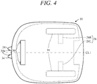
- FIG. 4 is a top view of the autonomously navigating work machine of FIG. 2
- FIG. 5 is a block diagram showing input-output relationships of an ECU (Electronic Control Unit) of the autonomously navigating work machine of FIG. 2
- FIG. 6 is an explanatory diagram of a work area to be serviced by the autonomously navigating work machine of FIG. 1 .
- Reference numeral 1 in FIG. 1 designates a work zone boundary demarcation apparatus of an autonomously navigating work machine (hereinafter called “apparatus”).
- the autonomously navigating work machine (hereinafter called “work machine 10") is a lawnmower, like that best shown in FIG. 2 .
- a single work machine 10 suffices, this embodiment assumes use of multiple work machines (e.g., three machines, as shown in FIG. 1 ), each of which is assigned to service its own work area AR.
- the apparatus 1 is equipped with a computer 2.
- the computer 2 comprises a processor (CPU) 2a, a memory 2b and an input/output circuit (I/O) 2c, which are interconnected through a bus.
- a display 4, and a keyboard, mouse, touch panel and other input equipment 6 are connected to the computer 2.
- a simulation program 2b1 for simulating work of at least one work machine 10 in the work area AR is loaded in the memory 2b of the computer 2.
- the simulation program 2b1 is an interactive program that allows a user or other operator to perform simulation in accordance with conditions inputted through the input equipment 6 and that displays the results on the display 4.
- a body (base member) 12 of the work machine 10 comprises a chassis 12a and a frame 12b attached to the chassis 12a.
- the work machine 10 is equipped with two (left and right) front wheels 14 of relatively small diameter fixed through stays 12a1 to longitudinal (fore-aft) front end of the chassis 12a and with left and right rear wheels 16 of relatively large diameter directly attached to rear end of the chassis 12a.
- a lawn mower work blade (work unit; hereinafter sometimes called “blade”) 20 is attached to the chassis 12a near the middle thereof and an electric motor (hereinafter called “work motor”) 22 is installed above it.
- the blade 20 is connected to the work motor 22 and driven to rotate thereby.
- a blade height regulation mechanism 24 manually operable by a user is connected to the blade 20. (Blade height can optionally be power regulated rather than manually.)
- propulsion motors 26L and 26R are attached to the chassis 12a rearward of the blade 20.
- the propulsion motors 26L and 26R are connected to the left and right rear wheels 16 and rotate the rear wheels 16 normally or reversely independently on the left and right.
- the work machine 10 is of such weight and size as to be portable by the user.
- the work machine 10 has a total length (fore-aft length) of about 71 cm, total width of about 55 cm, and height of about 30 cm.
- An onboard charging unit 30 and an onboard battery 32 connected thereto are housed at the rear of the work machine 10, and two battery charging terminals 34 are attached to the frame 12b so as to project forward in running direction.
- the work motor 22 and propulsion motors 26 are connected to the onboard battery 32 and are powered thereby.
- Related wiring is not illustrated (is omitted) in FIG. 1 .
- Two cameras (photographic equipment) 36 are installed on the front end of the work machine 10 to enable forward or stereographic (360°) observation.
- a contact sensor 40 attached to the frame 12b outputs an ON signal when the frame 12b detaches from the chassis 12a upon striking against an obstacle or foreign body.
- a housing box (not shown) installed near the middle of the work machine 10 houses a printed circuit board 42 carrying an electronic control unit (hereinafter sometimes called "ECU") 44.
- the ECU 44 comprises a microcomputer equipped with at least a CPU (processor) 44a, memory (ROM, EEPROM and RAM) 44b and I/O (input/output circuit) 44c.
- the printed circuit board 42 is further provided thereon, in the vicinity of the ECU 44, with an angular velocity sensor 46 that generates an output indicating angular velocity (yaw rate) around a center-of-gravity z-axis (gravity axis) of the work machine 10, an acceleration sensor 50 that generates an output indicating acceleration acting on the work machine 10 in orthogonal three-axis (x, y and z) directions, and a direction sensor 52 that generates an output indicating absolute orientation in response to terrestrial magnetism.
- angular velocity sensor 46 that generates an output indicating angular velocity (yaw rate) around a center-of-gravity z-axis (gravity axis) of the work machine 10
- an acceleration sensor 50 that generates an output indicating acceleration acting on the work machine 10 in orthogonal three-axis (x, y and z) directions
- a direction sensor 52 that generates an output indicating absolute orientation in response to terrestrial magnetism.
- Wheel speed sensors 54 installed near the left and right rear wheels 16 of the work machine 10 generate outputs indicating wheel speeds of the left and right rear wheels 16, and a lift sensor 56 installed between the chassis 12a and the frame 12b outputs an ON signal when the frame 12b is lifted (raised) off the chassis 12a by someone such as the user.
- a current sensor 60 installed on the onboard battery 32 generates an output indicating consumption of onboard battery 32 current.
- the work machine 10 is equipped with a main switch 62 for instructing start of work operation and the like and an emergency stop switch 64 for instructing emergency stop, both of which are operable by the user.
- the frame 12b of the work machine 10 has a large cutaway in its upper surface, in which a keyboard, touch panel or other input device 66 is installed for input of instructions and the like by the user, and a display 70 is also installed.
- the input device 66 and the display 70 are connected to the ECU 44, and the display 70 displays working modes and other various information in accordance with commands from the ECU 44.
- the ECU 44 is configured to communicate through the I/O 44c with the computer 2 of the apparatus 1, by wire or wirelessly, by means of a communication terminal 72, as shown in FIG. 3 .
- the communication terminal 72 is a smartphone or other such PDA (Portable Digital Assistant) with communication function.
- outputs of the cameras 36, contact sensor 40, angular velocity sensor 46 and other sensors and outputs of the main switch 62 and other switches are sent to the ECU 44 and inputted through the I/O 44c.
- Outputs of the cameras 36 are similarly sent to an ECU-equipped image processing unit 36a, in which captured images are generated.
- FIG. 6 is an explanatory bird's eye view of a work area AR.
- the work area AR can be divided into multiple zones ARn (e.g., AR1, AR2 and AR3) demarked by boundaries (boundary lines) 74.
- a charging station (hereinafter called charging ST) 76 for charging the onboard battery 32 of the work machine 10 is installed in the working area AR.
- the work area AR which for simplification of illustration is shown only partially in the drawing, is defined in its entirety in the memory 2b by a map MP that has its origin at the position of the charging ST 76 and is formed by arraying multiple cells Cmp in a biaxial orthogonal coordinate system (XY plane) of uniformly spaced horizontal and perpendicular lines referenced with respect to direction determined by the direction sensor 52.
- a map MP that has its origin at the position of the charging ST 76 and is formed by arraying multiple cells Cmp in a biaxial orthogonal coordinate system (XY plane) of uniformly spaced horizontal and perpendicular lines referenced with respect to direction determined by the direction sensor 52.
- markers formed like, for example, triangular blocks are placed at appropriate intervals along the perimeter and the boundaries 74, and the ECU 44 recognizes the full work area AR by detecting the markers from captured images generated by the image processing unit 36a.
- the ECU 44 supplies power of the onboard battery 32 to the propulsion motors 26 based on the other sensor outputs and outputs control values through the I/O 44c so as to run the propulsion motors 26 and control the work machine 10 to perform lawn mowing as it autonomously navigates in the work area AR.
- the processor 2a in the computer 2 performs as a boundary demarcation unit 2a1 that demarcates the boundaries 74 which divide the work area AR into multiple zones ARn, a simulation execution unit 2a2 that executes simulation of work performed by three work machines 10 in multiple zones ARn divided by boundaries 74 demarcated by the boundary demarcation unit 2a1, a boundary re-demarcation unit 2a3 that re-demarcates boundaries demarcated by the boundary demarcation unit 2a1 based on results of simulation executed by the simulation execution unit 2a2, a zone display unit 2a4 that displays multiple zones ARn of the work area AR divided in accordance with boundaries re-demarcated by the boundary re-demarcation unit 2a3, and a work instruction unit 2a5 that instructs at least one work machine 10 to perform work in multiple zones ARn of the work area AR divided in accordance with boundaries re-demarcated by the boundary re-demarcation unit 2a3.
- a boundary demarcation unit 2a1 that demarcates the boundaries 74 which
- the number of work machines 10 and the number of zones ARn are both defined as three in this embodiment, but, needless to say, neither the number of work machines 10 nor the number of work region zones ARn is limited to three.
- a single work machine 10 can sequentially service multiple zones ARn at staggered times.
- FIG. 7 is a flowchart concretely indicating processing performed by the processor 2a of the computer 2 of the work area zone boundary demarcation apparatus 1.
- boundaries 74 that divide the work area AR into multiple zones ARn are demarcated (processing performed by the boundary demarcation unit 2a1).
- the boundary demarcation unit 2a1 first tentatively demarcated the boundaries 74. For example, as shown in FIG. 6 , the boundary demarcation unit 2a1 randomly demarcates two points a and b on the perimeter of the work area AR, whose positions can be set by proximity to some point or be set to make area fraction of the respective zones equal.
- the boundary demarcation unit 2a1 demarcates the boundaries 74 so as to minimize intersections between the boundaries 74.
- the boundary demarcation unit 2a1 demarcates the boundaries 74 so as to minimize intersections between the boundaries 74.
- the boundary 74 can be defined by any among a number of straight line segments, efficiency is improved by defining the boundary74 using the longest straight line segment.
- the work area AR often includes a narrow path 80 of constricted passage width for the work machine 10, but the boundary demarcation unit 2a1 is configured to demarcate the boundaries 74 so as to minimize area of the narrow path 80 (i.e., number of the narrow paths 80 if plural).
- the narrow path 80 is by definition a passageway of width w not less than n times greater than and less than m times greater than lateral width of the work machine 10 (left-right direction width perpendicular to fore-aft center line CL1 of body in FIG. 3 ).
- the boundary demarcation unit 2a1 is configured to demarcate the boundaries 74 so as to minimize area or number of such narrow paths 80.
- FIG. 9 is a set of diagrams (i) and (ii) for explaining change of narrow path 80 area by boundary74 in the diagrams, an example is illustrated in which area of narrow path 80 is greater in (i) than in (ii). As area of the narrow path 80 is desirably made as small as possible, (ii) is preferable in the case shown in FIG. 9 .
- ARn and Arm are two among AR1, AR2 and AR3 of FIGs. 6 and 8 .
- the boundary demarcation unit 2a1 ascertains the positions of flower beds, trees, ponds and other unserviceable regions 82 in the work area AR from the cells Cmp of the map MP in response to input from the user or other operator and demarcates the boundaries 74 taking the ascertained unserviceable regions 82 into account.
- the boundary demarcation unit 2a1 is configured to update data regarding the work area AR at predetermined intervals such as every half year. Specifically, the boundary demarcation unit 2a1 determines at predetermined time intervals whether information including data regarding changes to the shape of the work area AR owing to construction, sale or other cause was inputted by the user, for example, and responds to such data having been inputted by updating the information regarding the work area AR.
- simulation of work performed by at least one work machine 10 in the three zones ARn divided by the demarcated boundaries 74 is executed (processing performed by the simulation execution unit 2a2).
- the simulation execution unit 2a2 performs simulation of work of at least one work machine 10 in the three zones ARn divided by the boundaries 74 demarcated by the boundary demarcation unit 2a1 in S10, it displays work time of the at least one work machine 10 on the display 4.
- the simulation execution unit 2a2 executes simulation of work of at least one work machine 10 in the three zones ARn divided by the boundaries 74 demarcated by the boundary demarcation unit 2a1 in S10, it also includes in the simulation travel time of the at least one work machine 10 between starting from a predetermined position (start point, e.g., charging ST 76) and arriving at its assigned zone ARn
- start point e.g., charging ST 76
- the simulation execution unit 2a2 again executes simulation of work of at least one working machine 10 in the multiple zones ARn divided by the boundaries 74 demarcated based on the updated data.
- the boundaries 74 demarcated by the boundary demarcation unit 2a1 in S10 are re-demarcated based on results of the simulation executed by the simulation execution unit (step) 2a2 in S12 (processing performed by the boundary re-demarcation unit 2a3).
- the boundary re-demarcation unit 2a3 re-demarcates the boundaries 74 demarcated by the boundary demarcation unit 2a1 and the simulation execution unit 2a2 again executes simulation of work of at least one work machine 10 in the multiple zones ARn divided by the re-demarcated boundaries 74.
- the simulation execution unit 2a2 thus re-executes simulation of work of at least one working machine 10 in the three zones ARn divided by the boundaries 74 re-demarcated by the boundary re-demarcation unit 2a3.
- the boundary re-demarcation unit 2a3 re-demarcates the boundaries demarcated by the boundary demarcation unit 2a1 so that the unserviced region comes to be included in an adjacent region and the simulation execution unit 2a2 again executes simulation of work of at least one work machine 10 in the multiple zones ARn divided by the re boundaries 74.
- a boundary 740 terminating ahead of the narrow path 80 is newly in place of the boundary 74 so that the unserviced region AR4 comes to be included in the work zone AR2 and simulation is executed in the new zone composed of AR4 + AR2 created by the newly demarcated boundary 740.
- At least one work machine 10 is prompted by an instruction to its ECU 44 to perform work in the multiple zones divided by the boundaries re-demarcated by the boundary re-demarcation unit 2a3 (work prompted by the work instruction unit 2a5).
- the zone boundary demarcation apparatus 1 of the work machine 10 can achieve improved efficiency when at least one work machine 10 performs work in a work area AR divided or demarcated into multiple zones ARn
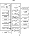
- FIG. 11 is a block diagram similar to FIG. 5 showing a work zone boundary demarcation apparatus of an autonomously navigating work machine according to a second embodiment of this invention and indicating input-output relationships of the ECU 44 of the work machine 10.
- At least one work machine 10 driven by propulsion motors 26 to be capable of autonomously navigating a work area AR comprises an ECU 44 constituted as a computer incorporating at least a processor 44a, a memory 44b and an input-output circuit 44c, and, similarly to what was explained with reference to FIG. 3 regarding the first embodiment, the memory 44b is loaded with a simulation program 44b1, similar to the simulation program 2b1, for simulating work of at least one work machine 10 in a work area.
- the processor 44a is configured to perform as a boundary demarcation unit 44a1, simulation execution unit 44a2, boundary re-demarcation unit 44a3, zone display unit 44a4 and work instruction unit 44a5 respectively similar to the boundary demarcation unit 2a1, simulation execution unit 2a2, boundary re-demarcation unit 2a3, zone display unit 2a4 and work instruction unit 2a5 of FIG. 3 .
- the work zone boundary demarcation apparatus 1 of the autonomously navigating work machine 10 is configured as described in the foregoing, it can, like the apparatus 1 of the first embodiment, achieve improved efficiency when at least one work machine 10 works in the work area AR divided into multiple zones ARn, and while its accuracy of simulation is slightly inferior to that of the first embodiment, it is advantageous for its simpler structure. Its other features and effects are no different from those of the first embodiment.
- the first and second embodiments of this invention is configured to have a work zone boundary demarcation apparatus (1) to demarcate boundaries (74) that divide a work area (AR) to be serviced by at least one autonomously navigating work machine (10) into multiple zones (ARn), comprising a computer (2, 44) having at least a processor (2a, 44a), a memory (2b, 44b), an input-output circuit (2c, 44c) and a simulation program (2b1, 44b1) loaded in the memory to simulate work of the work machine (10) in the work area, wherein the processor (2a,44a) is configured to perform as a boundary demarcation unit (2a1, 44a1, S10) that demarcates boundaries which divide the work area into multiple zones, a simulation execution unit (2a2, 44a2, S12) that executes simulation of work of the work machine in the multiple zones divided by the boundaries demarcated by the boundary demarcation unit, a boundary re-demarcation unit (2a3, 44a3, S14) that re-demarcates boundaries
- work times of the work machine 10 in the multiple zones ARn can be equalized by, for example, instructing the work machine 10 based on the display, so that efficiency when performing work by at least one work machine 10 can be improved by dividing a large work area AR into multiple zones ARn.
- the assumption in this context is that in the case of a single work machine 10, the multiple zones ARn are sequentially serviced at staggered times, and in the case of multiple work machines 10, each of the multiple zones is serviced by one of them.
- these embodiments are explained for the case of servicing each of multiple zones ARn with a single work machine 10, the embodiment is not limited to this mode and it is alternatively possible to service individual zones with multiple working machines 10.
- the apparatus includes a work instruction unit (2a5, 44a5, S18) that instructs the work machine(s) (10) to perform work in the multiple zones divided by the boundaries re-demarcated by the boundary re-demarcation unit.
- a work instruction unit (2a5, 44a5, S18) that instructs the work machine(s) (10) to perform work in the multiple zones divided by the boundaries re-demarcated by the boundary re-demarcation unit.
- the simulation execution unit (2a2, 44a2) re-executes simulation of work of the work machine in the multiple zones divided by the boundaries re-demarcated by the boundary re-demarcation unit (S12).
- the boundaries can be re-demarcated again based on the simulation results to more accurately equalize work times and still more thoroughly improve efficiency when dividing and servicing a large work area AR.
- the boundary re-demarcation unit (2a3, 44a3) re-demarcates the boundaries demarcated by the boundary demarcation unit and the simulation execution unit re-executes simulation of work of the work machine in the multiple zones divided by the re-demarcated boundaries (S14, S10).
- the boundary demarcation unit (2a1, 44a1) ascertains an unserviceable region(s) (82) in the work area (AR) and demarcates boundaries that divide the work area into multiple zones taking the ascertained unserviceable region(s) (82) into account (S14).
- the boundary demarcation unit (2a1, 44a1) ascertains an unserviceable region(s) (82) in the work area (AR) and demarcates boundaries that divide the work area into multiple zones taking the ascertained unserviceable region(s) (82) into account (S14).
- the simulation execution unit (2a2, 44a2) re-executes simulation of work of the work machine in the multiple zones divided by the re-demarcated boundaries (S12).
- the boundary demarcation unit (2a1, 44a1) updates data regarding the work area at predetermined intervals, and after data regarding the work area is updated by the boundary demarcation unit, the simulation execution unit (2a2, 44a2) re-executes simulation of work of the work machine in the multiple zones divided by the boundaries demarcated based on the updated data (S12).
- the boundary demarcation unit (2a1, 44a1) updates data regarding the work area at predetermined intervals
- the simulation execution unit (2a2, 44a2) re-executes simulation of work of the work machine in the multiple zones divided by the boundaries demarcated based on the updated data (S12).
- the boundary re-demarcation unit (2a3, 44a3) re-demarcates the boundaries demarcated by the boundary demarcation unit so as to include the unserviced region (AR4) in an area (AR2) adjacent to the unserviced region (AR4) and the simulation execution unit re-executes simulation of work of the work machine in the multiple zones divided by the re-demarcated boundaries (S14, S12).
- the apparatus includes a display (4, 70) connected to the computer and the boundary demarcation unit (2a1, 44a1) displays the demarcated boundaries on the display.
- the apparatus includes a display (4, 70) connected to the computer and the simulation execution unit (2a2, 44a2) displays work time of the work machine on the display at the time of executing simulation of work time of the work machine in the multiple zones divided by the boundaries demarcated by the boundary demarcation unit.
- the simulation execution unit (2a2, 44a2) when executing simulation of work of the work machine in the multiple zones divided by the boundaries demarcated by the boundary demarcation unit, includes in simulation travel time of the work machine up to arrival at the zone (S12).
- the boundary demarcation unit (2a1, 44a1) demarcates the boundaries dividing the work area into multiple zones so as to minimize intersections between the boundaries (S10).
- the boundary demarcation unit (2a1, 44a1) demarcates the boundary dividing the work area into multiple zones using the longest line segment among the multiple line segments (S10).
- the boundary demarcation unit (2a1. 44a1) demarcates the boundaries dividing the work area into multiple zones so as to minimize area of a narrow path(s) (80) of the work area (S10).
- the first embodiment of this invention is configured such that the work machine (10) is equipped with a computer (ECU 44) comprising at least a processor (44a), memory (44b) and input/output circuit (44c), and the zone display unit (2a4) instructs the processor (44a) of the computer (ECU 44) of the work machine (10) via the input/output circuit (2c) to display the multiple zones divided based on boundaries re-demarcated by the boundary re-demarcation unit (S16).
- a computer ECU 44
- the zone display unit (2a4 instructs the processor (44a) of the computer (ECU 44) of the work machine (10) via the input/output circuit (2c) to display the multiple zones divided based on boundaries re-demarcated by the boundary re-demarcation unit (S16).
- the second embodiment of this invention is configured such that the work machine (10) is driven by drive units (electric motors 26) to be capable of autonomous navigation in the work area, and is equipped with a computer (ECU 44) comprising a processor (44a), memory (44b) and input/output circuit (44c), and wherein the memory (44b) is loaded with a simulation program (44b 1) that simulates work of the work machine in the work area and wherein the processor 44a is configured to perform as the boundary demarcation unit (44a1), simulation execution unit (44a2), boundary re-demarcation unit (44a3) and work instruction unit (44a4).
- the work machine 10 is applied as a lawn mowing machine in the foregoing description, this invention is not limited to this application but can also be applied to any of various other kinds of autonomously navigating work units.
- the work zone boundary demarcation apparatus of autonomously navigating work machine according to this invention can be used suitably in simulation related to autonomously navigating work machines.
- 1 work area zone boundary demarcation apparatus of an autonomously navigating work machine 2 computer, 2a processor, 2a1 boundary demarcation unit, 2a2 simulation execution unit, 2a3 boundary re-demarcation unit, 2a4 zone display unit, 2a5 work instruction unit, 2b memory, 2b1 simulation program, 2c input/output circuit, 4 display, 6 input equipment, 10 autonomously navigating work machine (work machine), 12 body, 14 front wheels, 16 rear wheels, 20 blade (work unit), 22 electric motor (work motor), 24 blade height regulation mechanism, 26 electric motor (propulsion motor), 30 onboard charging unit, 32 onboard battery, 34 battery charging terminals, 36 camera, 36a image processing unit, 44 electronic control unit (ECU), 44a processor, 44a1 boundary demarcation unit, 44a2 simulation execution unit, 44a3 boundary re-demarcation unit, 44a4 zone display unit, 44a5 work instruction unit, 44b memory, 44b1 simulation program, 46 angular velocity sensor, 50 acceleration sensor, 52 direction sensor, 66 input device, 70 display, 72
Landscapes
- Engineering & Computer Science (AREA)
- Physics & Mathematics (AREA)
- Radar, Positioning & Navigation (AREA)
- General Physics & Mathematics (AREA)
- Remote Sensing (AREA)
- Automation & Control Theory (AREA)
- Aviation & Aerospace Engineering (AREA)
- Theoretical Computer Science (AREA)
- General Engineering & Computer Science (AREA)
- Evolutionary Computation (AREA)
- Geometry (AREA)
- Computer Hardware Design (AREA)
- Biophysics (AREA)
- Computational Linguistics (AREA)
- Molecular Biology (AREA)
- Mathematical Physics (AREA)
- Software Systems (AREA)
- General Health & Medical Sciences (AREA)
- Data Mining & Analysis (AREA)
- Computing Systems (AREA)
- Biomedical Technology (AREA)
- Artificial Intelligence (AREA)
- Life Sciences & Earth Sciences (AREA)
- Health & Medical Sciences (AREA)
- Control Of Position, Course, Altitude, Or Attitude Of Moving Bodies (AREA)
- Operation Control Of Excavators (AREA)
Abstract
Description
- This invention relates to a work area zone boundary demarcation apparatus of an autonomously navigating work machine, namely, an apparatus for demarking boundaries that divide a work area to be serviced by an autonomously navigating work machine into multiple zones.
- Various technologies have been proposed for operating a work machine to autonomously navigate and perform lawn mowing in a designated work area of a garden, golf course or other ground planted with grass (lawn) or to autonomously navigate and perform cleaning work in a designated work area of a floor or the like inside a building. Patent Document 1 can be cited as an example of such a technology. The technology described in Patent Document 1 uses a current-carrying wire to demarcate a work area to be autonomously navigated by a lawnmower work machine.
- Patent Document 1: Specification of
U.S. Unexamined Patent Application Publication No. 2014/0058611 - With regard to such technologies, there sometimes arise cases in which it is more efficient to divide or demarcate the work area into a number of zones and perform work separately in the individual zones. The object of this invention is therefore to provide a work zone boundary demarcation apparatus of an autonomously navigating work machine that achieves improved work efficiency by dividing the work area into multiple zones.
- In order to achieve the object, this invention provides a work zone boundary demarcation apparatus to demarcate boundaries that divide a work area to be serviced by at least one autonomously navigating work machine into multiple zones, comprising:
a computer having at least a processor, a memory, an input-output circuit and a simulation program loaded in the memory to simulate work of the work machine in the work area; characterized in that the processor is configured to perform as: a boundary demarcation unit that demarcates boundaries which divide the work area into multiple zones, a simulation execution unit that executes simulation of work of the work machine in the multiple zones divided by the boundaries demarcated by the boundary demarcation unit, a boundary re-demarcation unit that re-demarcates boundaries demarcated by the boundary demarcation unit based on results of the simulation executed by the simulation execution unit, and a zone display unit that displays the multiple zones divided by the boundaries re-demarcated by the boundary re-demarcation unit. -
-
FIG. 1 is a conceptual diagram showing an overview of a work zone boundary demarcation apparatus of an autonomously navigating work machine according to a first embodiment of this invention; -
FIG. 2 is an explanatory side view of the autonomously navigating work machine ofFIG. 1 ; -
FIG. 3 is an explanatory diagram detailing configuration of a computer ofFIG. 1 ; -
FIG. 4 is a top view of the autonomously navigating work machine ofFIG. 2 ; -
FIG. 5 is a block diagram showing input-output relationships of an ECU of the autonomously navigating work machine ofFIG. 2 ; -
FIG. 6 is an explanatory diagram of a work area to be serviced by the autonomously navigating work machine ofFIG. 1 ; -
FIG. 7 is a flowchart concretely indicating processing performed by the processor of the computer of the work area zone boundary demarcation apparatus ofFIG. 1 ; -
FIG. 8 is still an explanatory diagram of a work area to be serviced by the autonomously navigating work machine ofFIG. 1 ; -
FIG. 9 is yet an explanatory diagram of a work area to be serviced by the autonomously navigating work machine ofFIG. 1 ; -
FIG. 10 is yet still an explanatory diagram of a work area to be serviced by the autonomously navigating work machine ofFIG. 1 ; and -
FIG. 11 is a block diagram, similar toFIG. 5 , but showing a work zone boundary demarcation apparatus of an autonomously navigating work machine according to a second embodiment of this invention and indicating input-output relationships of an ECU of the work machine. -
FIG. 1 is a conceptual diagram showing an overview of a work zone boundary demarcation apparatus of an autonomously navigating work machine according to a first embodiment of this invention;FIG. 2 is an explanatory side view of the autonomously navigating work machine ofFIG. 1 ;FIG. 3 is an explanatory diagram detailing configuration of a computer ofFIG. 1 ;FIG. 4 is a top view of the autonomously navigating work machine ofFIG. 2 ;FIG. 5 is a block diagram showing input-output relationships of an ECU (Electronic Control Unit) of the autonomously navigating work machine ofFIG. 2 ; andFIG. 6 is an explanatory diagram of a work area to be serviced by the autonomously navigating work machine ofFIG. 1 . - Reference numeral 1 in
FIG. 1 designates a work zone boundary demarcation apparatus of an autonomously navigating work machine (hereinafter called "apparatus"). In this embodiment, the autonomously navigating work machine (hereinafter called "work machine 10") is a lawnmower, like that best shown inFIG. 2 . Although asingle work machine 10 suffices, this embodiment assumes use of multiple work machines (e.g., three machines, as shown inFIG. 1 ), each of which is assigned to service its own work area AR. - The apparatus 1 is equipped with a
computer 2. As shown inFIG. 3 , thecomputer 2 comprises a processor (CPU) 2a, amemory 2b and an input/output circuit (I/O) 2c, which are interconnected through a bus. Adisplay 4, and a keyboard, mouse, touch panel andother input equipment 6 are connected to thecomputer 2. - A simulation program 2b1 for simulating work of at least one
work machine 10 in the work area AR is loaded in thememory 2b of thecomputer 2. The simulation program 2b1 is an interactive program that allows a user or other operator to perform simulation in accordance with conditions inputted through theinput equipment 6 and that displays the results on thedisplay 4. - There now follows an explanation of the
work machine 10 with reference toFIG. 2 onward. A body (base member) 12 of thework machine 10 comprises achassis 12a and aframe 12b attached to thechassis 12a. Thework machine 10 is equipped with two (left and right)front wheels 14 of relatively small diameter fixed through stays 12a1 to longitudinal (fore-aft) front end of thechassis 12a and with left and rightrear wheels 16 of relatively large diameter directly attached to rear end of thechassis 12a. - A lawn mower work blade (work unit; hereinafter sometimes called "blade") 20 is attached to the
chassis 12a near the middle thereof and an electric motor (hereinafter called "work motor") 22 is installed above it. Theblade 20 is connected to thework motor 22 and driven to rotate thereby. A bladeheight regulation mechanism 24 manually operable by a user is connected to theblade 20. (Blade height can optionally be power regulated rather than manually.) - Two electric motors (drive units; hereinafter called "propulsion motors") 26L and 26R are attached to the
chassis 12a rearward of theblade 20. Thepropulsion motors rear wheels 16 and rotate therear wheels 16 normally or reversely independently on the left and right. - The
work machine 10 is of such weight and size as to be portable by the user. For example, thework machine 10 has a total length (fore-aft length) of about 71 cm, total width of about 55 cm, and height of about 30 cm. An onboardcharging unit 30 and anonboard battery 32 connected thereto are housed at the rear of thework machine 10, and twobattery charging terminals 34 are attached to theframe 12b so as to project forward in running direction. Thework motor 22 andpropulsion motors 26 are connected to theonboard battery 32 and are powered thereby. Related wiring is not illustrated (is omitted) inFIG. 1 . - Two cameras (photographic equipment) 36 are installed on the front end of the
work machine 10 to enable forward or stereographic (360°) observation. And acontact sensor 40 attached to theframe 12b outputs an ON signal when theframe 12b detaches from thechassis 12a upon striking against an obstacle or foreign body. - A housing box (not shown) installed near the middle of the
work machine 10 houses a printedcircuit board 42 carrying an electronic control unit (hereinafter sometimes called "ECU") 44. As shown inFIG. 5 , the ECU 44 comprises a microcomputer equipped with at least a CPU (processor) 44a, memory (ROM, EEPROM and RAM) 44b and I/O (input/output circuit) 44c. - The
printed circuit board 42 is further provided thereon, in the vicinity of theECU 44, with anangular velocity sensor 46 that generates an output indicating angular velocity (yaw rate) around a center-of-gravity z-axis (gravity axis) of thework machine 10, anacceleration sensor 50 that generates an output indicating acceleration acting on thework machine 10 in orthogonal three-axis (x, y and z) directions, and adirection sensor 52 that generates an output indicating absolute orientation in response to terrestrial magnetism. -
Wheel speed sensors 54 installed near the left and rightrear wheels 16 of thework machine 10 generate outputs indicating wheel speeds of the left and rightrear wheels 16, and alift sensor 56 installed between thechassis 12a and theframe 12b outputs an ON signal when theframe 12b is lifted (raised) off thechassis 12a by someone such as the user. Acurrent sensor 60 installed on theonboard battery 32 generates an output indicating consumption ofonboard battery 32 current. - The
work machine 10 is equipped with a main switch 62 for instructing start of work operation and the like and an emergency stop switch 64 for instructing emergency stop, both of which are operable by the user. In addition, theframe 12b of thework machine 10 has a large cutaway in its upper surface, in which a keyboard, touch panel orother input device 66 is installed for input of instructions and the like by the user, and adisplay 70 is also installed. - The
input device 66 and thedisplay 70 are connected to theECU 44, and thedisplay 70 displays working modes and other various information in accordance with commands from theECU 44. Moreover, the ECU 44 is configured to communicate through the I/O 44c with thecomputer 2 of the apparatus 1, by wire or wirelessly, by means of acommunication terminal 72, as shown inFIG. 3 . Thecommunication terminal 72 is a smartphone or other such PDA (Portable Digital Assistant) with communication function. - As shown in
FIG. 5 , outputs of thecameras 36,contact sensor 40,angular velocity sensor 46 and other sensors and outputs of the main switch 62 and other switches are sent to theECU 44 and inputted through the I/O 44c. Outputs of thecameras 36 are similarly sent to an ECU-equippedimage processing unit 36a, in which captured images are generated. -
FIG. 6 is an explanatory bird's eye view of a work area AR. The work area AR can be divided into multiple zones ARn (e.g., AR1, AR2 and AR3) demarked by boundaries (boundary lines) 74. A charging station (hereinafter called charging ST) 76 for charging theonboard battery 32 of thework machine 10 is installed in the working area AR. - The work area AR, which for simplification of illustration is shown only partially in the drawing, is defined in its entirety in the
memory 2b by a map MP that has its origin at the position of the chargingST 76 and is formed by arraying multiple cells Cmp in a biaxial orthogonal coordinate system (XY plane) of uniformly spaced horizontal and perpendicular lines referenced with respect to direction determined by thedirection sensor 52. - In the actual work area AR, markers formed like, for example, triangular blocks are placed at appropriate intervals along the perimeter and the
boundaries 74, and theECU 44 recognizes the full work area AR by detecting the markers from captured images generated by theimage processing unit 36a. - Moreover, the
ECU 44 supplies power of theonboard battery 32 to thepropulsion motors 26 based on the other sensor outputs and outputs control values through the I/O 44c so as to run thepropulsion motors 26 and control thework machine 10 to perform lawn mowing as it autonomously navigates in the work area AR. - Returning to
FIG. 3 to continue explanation of thecomputer 2 of the apparatus 1, theprocessor 2a in thecomputer 2 performs as a boundary demarcation unit 2a1 that demarcates theboundaries 74 which divide the work area AR into multiple zones ARn, a simulation execution unit 2a2 that executes simulation of work performed by threework machines 10 in multiple zones ARn divided byboundaries 74 demarcated by the boundary demarcation unit 2a1, a boundary re-demarcation unit 2a3 that re-demarcates boundaries demarcated by the boundary demarcation unit 2a1 based on results of simulation executed by the simulation execution unit 2a2, a zone display unit 2a4 that displays multiple zones ARn of the work area AR divided in accordance with boundaries re-demarcated by the boundary re-demarcation unit 2a3, and a work instruction unit 2a5 that instructs at least onework machine 10 to perform work in multiple zones ARn of the work area AR divided in accordance with boundaries re-demarcated by the boundary re-demarcation unit 2a3. - For convenience of illustration, the number of
work machines 10 and the number of zones ARn are both defined as three in this embodiment, but, needless to say, neither the number ofwork machines 10 nor the number of work region zones ARn is limited to three. To give a specific example, asingle work machine 10 can sequentially service multiple zones ARn at staggered times. -
FIG. 7 is a flowchart concretely indicating processing performed by theprocessor 2a of thecomputer 2 of the work area zone boundary demarcation apparatus 1. - Now to explain, in S10,
boundaries 74 that divide the work area AR into multiple zones ARn are demarcated (processing performed by the boundary demarcation unit 2a1). - Specifically, the boundary demarcation unit 2a1 first tentatively demarcated the
boundaries 74. For example, as shown inFIG. 6 , the boundary demarcation unit 2a1 randomly demarcates two points a and b on the perimeter of the work area AR, whose positions can be set by proximity to some point or be set to make area fraction of the respective zones equal. - In addition, the boundary demarcation unit 2a1 demarcates the
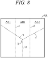
boundaries 74 so as to minimize intersections between theboundaries 74. As is clear from the example shown inFIG. 8 , when the case of using straight lines c and d each comprising of a single straight line segment is compared to the case of using straight lines e, f and g each comprising of a segment of a bent straight line, it is seen that the former case has 0 straight line intersections while the latter case has 1 straight line intersection (h). - In the division according to the latter case having more intersections than in the former case, shape of the area becomes complicated, and since there come to be fewer maximum length straight line distances in the area, the
work machine 10 has to make more laps and work time increases in proportion. Accordingly, when theboundary 74 can be defined by any among a number of straight line segments, efficiency is improved by defining the boundary74 using the longest straight line segment. - As shown in
FIG. 6 , the work area AR often includes anarrow path 80 of constricted passage width for thework machine 10, but the boundary demarcation unit 2a1 is configured to demarcate theboundaries 74 so as to minimize area of the narrow path 80 (i.e., number of thenarrow paths 80 if plural). - The
narrow path 80 is by definition a passageway of width w not less than n times greater than and less than m times greater than lateral width of the work machine 10 (left-right direction width perpendicular to fore-aft center line CL1 of body inFIG. 3 ). The boundary demarcation unit 2a1 is configured to demarcate theboundaries 74 so as to minimize area or number of suchnarrow paths 80. - Now to explain this with reference to
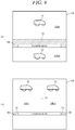
FIG. 9 , which is a set of diagrams (i) and (ii) for explaining change ofnarrow path 80 area by boundary74 in the diagrams, an example is illustrated in which area ofnarrow path 80 is greater in (i) than in (ii). As area of thenarrow path 80 is desirably made as small as possible, (ii) is preferable in the case shown inFIG. 9 . InFIG. 9 , ARn and Arm are two among AR1, AR2 and AR3 ofFIGs. 6 and8 . - In addition, the boundary demarcation unit 2a1 ascertains the positions of flower beds, trees, ponds and other
unserviceable regions 82 in the work area AR from the cells Cmp of the map MP in response to input from the user or other operator and demarcates theboundaries 74 taking the ascertainedunserviceable regions 82 into account. - Moreover, the boundary demarcation unit 2a1 is configured to update data regarding the work area AR at predetermined intervals such as every half year. Specifically, the boundary demarcation unit 2a1 determines at predetermined time intervals whether information including data regarding changes to the shape of the work area AR owing to construction, sale or other cause was inputted by the user, for example, and responds to such data having been inputted by updating the information regarding the work area AR.
- Returning to the explanation of the flowchart of
FIG. 7 , next, in S12, simulation of work performed by at least onework machine 10 in the three zones ARn divided by the demarcatedboundaries 74 is executed (processing performed by the simulation execution unit 2a2). - Now to explain, when the simulation execution unit 2a2 performs simulation of work of at least one
work machine 10 in the three zones ARn divided by theboundaries 74 demarcated by the boundary demarcation unit 2a1 in S10, it displays work time of the at least onework machine 10 on thedisplay 4. - Moreover, when the simulation execution unit 2a2 executes simulation of work of at least one
work machine 10 in the three zones ARn divided by theboundaries 74 demarcated by the boundary demarcation unit 2a1 in S10, it also includes in the simulation travel time of the at least onework machine 10 between starting from a predetermined position (start point, e.g., charging ST 76) and arriving at its assigned zone ARn - In addition, after the boundary demarcation unit 2a1 updates data regarding the work area AR, the simulation execution unit 2a2 again executes simulation of work of at least one working
machine 10 in the multiple zones ARn divided by theboundaries 74 demarcated based on the updated data. - Returning to the explanation of the flowchart of
FIG. 7 , next, in S14, theboundaries 74 demarcated by the boundary demarcation unit 2a1 in S10 are re-demarcated based on results of the simulation executed by the simulation execution unit (step) 2a2 in S12 (processing performed by the boundary re-demarcation unit 2a3). - The reasoning here is that since the boundary demarcation unit 2a1 only tentatively demarcates the
boundaries 74 in S10 at the start of the processing, the results of the simulation executed by the simulation execution unit 2a2 are highly likely to lead to the conclusion that the workloads of the three zones ARn divided by thetentative boundaries 74 demarcated by the boundary demarcation unit 2a1 in S10 are not equal. - Therefore, when it is determined from the results of the simulation executed by the simulation execution unit 2a2 in S12 that the workloads of the three zones ARn divided by the
boundaries 74 demarcated by the boundary demarcation unit 2a1 in S10 are not equal, the boundary re-demarcation unit 2a3 re-demarcates theboundaries 74 demarcated by the boundary demarcation unit 2a1 and the simulation execution unit 2a2 again executes simulation of work of at least onework machine 10 in the multiple zones ARn divided by there-demarcated boundaries 74. - The simulation execution unit 2a2 thus re-executes simulation of work of at least one working
machine 10 in the three zones ARn divided by theboundaries 74 re-demarcated by the boundary re-demarcation unit 2a3. - Moreover, when it is determined from the results of the simulation executed by the simulation execution unit 2a2 that an unserviced region remains in any of the work region zones ARn, the boundary re-demarcation unit 2a3 re-demarcates the boundaries demarcated by the boundary demarcation unit 2a1 so that the unserviced region comes to be included in an adjacent region and the simulation execution unit 2a2 again executes simulation of work of at least one
work machine 10 in the multiple zones ARn divided by there boundaries 74. - For example, assume that when work zones AR1 and AR2 are divided by a
boundary 74 in S10, as shown inFIG. 10 , a resulting region AR4 adjacent to anarrow path 80 becomes an unserviced region. - In such a case, therefore, a
boundary 740 terminating ahead of thenarrow path 80 is newly in place of theboundary 74 so that the unserviced region AR4 comes to be included in the work zone AR2 and simulation is executed in the new zone composed of AR4 + AR2 created by the newly demarcatedboundary 740. - Although the shape of the work area AR in the explanation of this embodiment appears different among
FIGs. 1 ,6 ,8 ,9 and10 , this is solely for convenience of illustration and explanation, and the actual work area AR is of one and the same shape. - Returning to the explanation of the flowchart of
FIG. 7 , next, in S16, the multiple zones divided by the boundaries re-demarcated by the boundary demarcation unit 2a3 are displayed (processing performed by the zone display unit 2a4 that results in display content nearly the same as that ofFIG. 6 ). - Next, in S18, at least one
work machine 10 is prompted by an instruction to itsECU 44 to perform work in the multiple zones divided by the boundaries re-demarcated by the boundary re-demarcation unit 2a3 (work prompted by the work instruction unit 2a5). - Owing to its aforesaid configuration, the zone boundary demarcation apparatus 1 of the
work machine 10 according to the first embodiment can achieve improved efficiency when at least onework machine 10 performs work in a work area AR divided or demarcated into multiple zones ARn -
FIG. 11 is a block diagram similar toFIG. 5 showing a work zone boundary demarcation apparatus of an autonomously navigating work machine according to a second embodiment of this invention and indicating input-output relationships of theECU 44 of thework machine 10. - As illustrated with respect to the second embodiment, at least one
work machine 10 driven bypropulsion motors 26 to be capable of autonomously navigating a work area AR comprises anECU 44 constituted as a computer incorporating at least aprocessor 44a, amemory 44b and an input-output circuit 44c, and, similarly to what was explained with reference toFIG. 3 regarding the first embodiment, thememory 44b is loaded with a simulation program 44b1, similar to the simulation program 2b1, for simulating work of at least onework machine 10 in a work area. - Moreover, the
processor 44a is configured to perform as a boundary demarcation unit 44a1, simulation execution unit 44a2, boundary re-demarcation unit 44a3, zone display unit 44a4 and work instruction unit 44a5 respectively similar to the boundary demarcation unit 2a1, simulation execution unit 2a2, boundary re-demarcation unit 2a3, zone display unit 2a4 and work instruction unit 2a5 ofFIG. 3 . - As the work zone boundary demarcation apparatus 1 of the autonomously navigating
work machine 10 according to the second embodiment is configured as described in the foregoing, it can, like the apparatus 1 of the first embodiment, achieve improved efficiency when at least onework machine 10 works in the work area AR divided into multiple zones ARn, and while its accuracy of simulation is slightly inferior to that of the first embodiment, it is advantageous for its simpler structure. Its other features and effects are no different from those of the first embodiment. - As described in the foregoing, the first and second embodiments of this invention is configured to have a work zone boundary demarcation apparatus (1) to demarcate boundaries (74) that divide a work area (AR) to be serviced by at least one autonomously navigating work machine (10) into multiple zones (ARn), comprising a computer (2, 44) having at least a processor (2a, 44a), a memory (2b, 44b), an input-output circuit (2c, 44c) and a simulation program (2b1, 44b1) loaded in the memory to simulate work of the work machine (10) in the work area, wherein the processor (2a,44a) is configured to perform as a boundary demarcation unit (2a1, 44a1, S10) that demarcates boundaries which divide the work area into multiple zones, a simulation execution unit (2a2, 44a2, S12) that executes simulation of work of the work machine in the multiple zones divided by the boundaries demarcated by the boundary demarcation unit, a boundary re-demarcation unit (2a3, 44a3, S14) that re-demarcates boundaries demarcated by the boundary demarcation unit based on results of the simulation executed by the simulation execution unit, and a zone display unit (2a4, 44a4, S16) that displays the multiple zones divided by the boundaries re-demarcated by the boundary re-demarcation unit. With this, work times of the
work machine 10 in the multiple zones ARn can be equalized by, for example, instructing thework machine 10 based on the display, so that efficiency when performing work by at least onework machine 10 can be improved by dividing a large work area AR into multiple zones ARn. The assumption in this context is that in the case of asingle work machine 10, the multiple zones ARn are sequentially serviced at staggered times, and in the case ofmultiple work machines 10, each of the multiple zones is serviced by one of them. Although these embodiments are explained for the case of servicing each of multiple zones ARn with asingle work machine 10, the embodiment is not limited to this mode and it is alternatively possible to service individual zones with multiple workingmachines 10. - Moreover, it is configured such that the apparatus includes a work instruction unit (2a5, 44a5, S18) that instructs the work machine(s) (10) to perform work in the multiple zones divided by the boundaries re-demarcated by the boundary re-demarcation unit. With this, work times of the work machine(s) 10 in the multiple zones ARn can, as stated earlier, be equalized to enable improved efficiency when a large work area AR is divided into multiple zones ARn and serviced.
- In addition, it is configured such that the simulation execution unit (2a2, 44a2) re-executes simulation of work of the work machine in the multiple zones divided by the boundaries re-demarcated by the boundary re-demarcation unit (S12). With this, the boundaries can be re-demarcated again based on the simulation results to more accurately equalize work times and still more thoroughly improve efficiency when dividing and servicing a large work area AR.
- Furthermore, it is configured such that when workloads of the multiple zones divided by the boundaries demarcated by the boundary demarcation unit are determined from the results of the simulation executed by the simulation execution unit not to be equal, the boundary re-demarcation unit (2a3, 44a3) re-demarcates the boundaries demarcated by the boundary demarcation unit and the simulation execution unit re-executes simulation of work of the work machine in the multiple zones divided by the re-demarcated boundaries (S14, S10). With this, work times can be more accurately equalized to still more thoroughly improve efficiency when dividing and servicing a large work area AR.
- Moreover, it is configured such that the boundary demarcation unit (2a1, 44a1) ascertains an unserviceable region(s) (82) in the work area (AR) and demarcates boundaries that divide the work area into multiple zones taking the ascertained unserviceable region(s) (82) into account (S14). With this, work times can be more accurately equalized to still more thoroughly improve efficiency when dividing and servicing a large work area AR.
- Still further, it is configured such that when the boundary demarcation unit demarcates boundaries dividing the work area into multiple zones taking the unserviceable region(s) (82) into account, the simulation execution unit (2a2, 44a2) re-executes simulation of work of the work machine in the multiple zones divided by the re-demarcated boundaries (S12). With this, work times can be more accurately equalized to still more thoroughly improve efficiency when dividing and servicing a large work area AR.
- In addition, it is configured such that the boundary demarcation unit (2a1, 44a1) updates data regarding the work area at predetermined intervals, and after data regarding the work area is updated by the boundary demarcation unit, the simulation execution unit (2a2, 44a2) re-executes simulation of work of the work machine in the multiple zones divided by the boundaries demarcated based on the updated data (S12). With this, work times can be more accurately equalized to still more thoroughly improve efficiency when dividing and servicing a large work area AR.
- Further, it is configured such that when it is determined from the results of simulation executed by the simulation execution unit that an unserviced region (AR4) remains in any of the multiple zones, the boundary re-demarcation unit (2a3, 44a3) re-demarcates the boundaries demarcated by the boundary demarcation unit so as to include the unserviced region (AR4) in an area (AR2) adjacent to the unserviced region (AR4) and the simulation execution unit re-executes simulation of work of the work machine in the multiple zones divided by the re-demarcated boundaries (S14, S12). With this, in addition to the aforesaid effects, occurrence of unserviced regions can be effectively prevented.
- Moreover, it is configured such that the apparatus includes a display (4, 70) connected to the computer and the boundary demarcation unit (2a1, 44a1) displays the demarcated boundaries on the display. With this, in addition to the aforesaid effects, equalization of the divided zones can be visually monitored.
- Moreover, it is configured such that the apparatus includes a display (4, 70) connected to the computer and the simulation execution unit (2a2, 44a2) displays work time of the work machine on the display at the time of executing simulation of work time of the work machine in the multiple zones divided by the boundaries demarcated by the boundary demarcation unit. With this, in addition to the aforesaid effects, equalization of the divided zones can be visually monitored.
- In addition, it is configured such that when executing simulation of work of the work machine in the multiple zones divided by the boundaries demarcated by the boundary demarcation unit, the simulation execution unit (2a2, 44a2) includes in simulation travel time of the work machine up to arrival at the zone (S12). With this, work times can be more accurately equalized to still more thoroughly improve efficiency when dividing and servicing a large work area AR
- Still further, it is configured such that the boundary demarcation unit (2a1, 44a1) demarcates the boundaries dividing the work area into multiple zones so as to minimize intersections between the boundaries (S10). With this, in addition to the aforesaid effects, number of laps made by the
work machine 10 while working can be reduced to still more thoroughly improve efficiency when dividing and servicing a large work area AR - In addition, it is configured such that when the boundary can be defined by any among a number of straight line segments, the boundary demarcation unit (2a1, 44a1) demarcates the boundary dividing the work area into multiple zones using the longest line segment among the multiple line segments (S10). With this, in addition to the aforesaid effects, number of laps made by the
work machine 10 can be reduced to still more thoroughly improve efficiency when dividing and servicing a large work area AR - Moreover, it is configured such that the boundary demarcation unit (2a1. 44a1) demarcates the boundaries dividing the work area into multiple zones so as to minimize area of a narrow path(s) (80) of the work area (S10). With this, in addition to the aforesaid effects, work in the narrow path(s) 80 can be reduced to still more thoroughly improve efficiency when dividing and servicing a large work area AR
- Further, the first embodiment of this invention is configured such that the work machine (10) is equipped with a computer (ECU 44) comprising at least a processor (44a), memory (44b) and input/output circuit (44c), and the zone display unit (2a4) instructs the processor (44a) of the computer (ECU 44) of the work machine (10) via the input/output circuit (2c) to display the multiple zones divided based on boundaries re-demarcated by the boundary re-demarcation unit (S16). With this, in addition to the aforesaid effects, it becomes possible, by executing simulation more accurately using a mainframe or
other computer 2 instead of the computer (ECU 44) installed in thework machine 10, to improve efficiency when servicing a large work area AR divided into multiple zones ARn - Moreover, the second embodiment of this invention is configured such that the work machine (10) is driven by drive units (electric motors 26) to be capable of autonomous navigation in the work area, and is equipped with a computer (ECU 44) comprising a processor (44a), memory (44b) and input/output circuit (44c), and wherein the memory (44b) is loaded with a simulation program (44b 1) that simulates work of the work machine in the work area and wherein the
processor 44a is configured to perform as the boundary demarcation unit (44a1), simulation execution unit (44a2), boundary re-demarcation unit (44a3) and work instruction unit (44a4). With this, in addition to the aforesaid effects, it becomes possible by means of a simple configuration to perform simulation and thereby achieve improved efficiency when servicing a large work area AR divided into multiple zones ARn - Although the
work machine 10 is applied as a lawn mowing machine in the foregoing description, this invention is not limited to this application but can also be applied to any of various other kinds of autonomously navigating work units. - The work zone boundary demarcation apparatus of autonomously navigating work machine according to this invention can be used suitably in simulation related to autonomously navigating work machines.
- 1 work area zone boundary demarcation apparatus of an autonomously navigating work machine, 2 computer, 2a processor, 2a1 boundary demarcation unit, 2a2 simulation execution unit, 2a3 boundary re-demarcation unit, 2a4 zone display unit, 2a5 work instruction unit, 2b memory, 2b1 simulation program, 2c input/output circuit, 4 display, 6 input equipment, 10 autonomously navigating work machine (work machine), 12 body, 14 front wheels, 16 rear wheels, 20 blade (work unit), 22 electric motor (work motor), 24 blade height regulation mechanism, 26 electric motor (propulsion motor), 30 onboard charging unit, 32 onboard battery, 34 battery charging terminals, 36 camera, 36a image processing unit, 44 electronic control unit (ECU), 44a processor, 44a1 boundary demarcation unit, 44a2 simulation execution unit, 44a3 boundary re-demarcation unit, 44a4 zone display unit, 44a5 work instruction unit, 44b memory, 44b1 simulation program, 46 angular velocity sensor, 50 acceleration sensor, 52 direction sensor, 66 input device, 70 display, 72 communication terminal, 74 boundary, 76 charging station (ST), 80 narrow path, 82 unserviceable region
Claims (16)
- A work zone boundary demarcation apparatus to demarcate boundaries that divide a work area to be serviced by at least one autonomously navigating work machine into multiple zones, comprising:a computer having at least a processor, a memory, an input-output circuit and a simulation program loaded in the memory to simulate work of the work machine in the work area;wherein the processor is configured to perform as:a boundary demarcation unit that demarcates boundaries which divide the work area into multiple zones,a simulation execution unit that executes simulation of work of the work machine in the multiple zones divided by the boundaries demarcated by the boundary demarcation unit,a boundary re-demarcation unit that re-demarcates boundaries demarcated by the boundary demarcation unit based on results of the simulation executed by the simulation execution unit, anda zone display unit that displays the multiple zones divided by the boundaries re-demarcated by the boundary re-demarcation unit.
- The apparatus according to claim 1, further including:
a work instruction unit that instructs the work machine to perform work in the multiple zones divided by the boundaries re-demarcated by the boundary re-demarcation unit. - The apparatus according to claim 1 or 2, wherein the simulation execution unit re-executes simulation of work of the work machine in the multiple zones divided by the boundaries re-demarcated by the boundary re-demarcation unit.
- The apparatus according to any of claims 1 to 3, wherein when workloads of the multiple zones divided by the boundaries demarcated by the boundary demarcation unit are determined from the results of the simulation executed by the simulation execution unit not to be equal, the boundary re-demarcation unit re-demarcates the boundaries demarcated by the boundary demarcation unit and the simulation execution unit re-executes simulation of work of the work machine in the multiple zones divided by the re-demarcated boundaries.
- The apparatus according to any of claims 1 to 4, wherein the boundary demarcation unit ascertains an unserviceable region in the work area and demarcates boundaries that divide the work area into multiple zones taking the ascertained unserviceable region into account.
- The apparatus according to claim 5, wherein when the boundary demarcation unit demarcates boundaries dividing the work area into multiple zones taking the unserviceable region into account, the simulation execution unit re-executes simulation of work of the work machine in the multiple zones divided by the re-demarcated boundaries.
- The apparatus according to any of claims 1 to 6, wherein the boundary demarcation unit updates data regarding the work area at predetermined intervals, and after data regarding the work area is updated by the boundary demarcation unit, the simulation execution unit re-executes simulation of work of the work machine in the multiple zones divided by the boundaries demarcated based on the updated data.
- The apparatus according to any of claims 1 to 7, wherein when it is determined from the results of simulation executed by the simulation execution unit that an unserviced region remains in any of the multiple zones, the boundary re-demarcation unit re-demarcates the boundaries demarcated by the boundary demarcation unit so as to include the unserviced region in an area adjacent to the unserviced region and the simulation execution unit re-executes simulation of work of the work machine in the multiple zones divided by the re-demarcated boundaries.
- The apparatus according to any of claims 1 to 8, further including:
a display connected to the computer and the boundary demarcation unit displays the demarcated boundaries on the display. - The apparatus according to any of claims 1 to 9, further including:a display connected to the computer; andthe simulation execution unit displays work time of the work machine on the display at the time of executing simulation of work time of the work machine in the multiple zones divided by the boundaries demarcated by the boundary demarcation unit.
- The apparatus according to any of claims 1 to 10, wherein when executing simulation of work of the work machine in the multiple zones divided by the boundaries demarcated by the boundary demarcation unit, the simulation execution unit includes in simulation travel time of the work machine up to arrival at the zone.
- The apparatus according to any of claims 1 to 11, wherein the boundary demarcation unit demarcates the boundaries dividing the work area into multiple zones so as to minimize intersections between the boundaries.
- The apparatus according to any of claims 1 to 12, wherein when the boundary can be defined by any among a number of straight line segments, the boundary demarcation unit demarcates the boundary dividing the work area into multiple zones using the longest line segment among the multiple line segments.
- The apparatus according to any of claims 1 to 13, wherein the boundary demarcation unit demarcates the boundaries dividing the work area into multiple zones so as to minimize area of a narrow path of the work area.
- The apparatus according to any of claims 1 to 14, wherein the work machine is equipped with a computer comprising at least a processor, memory and input/output circuit, and the zone display unit instructs the processor of the computer of the work machine via the input/output circuit to display the multiple zones divided based on boundaries re-demarcated by the boundary re-demarcation unit.
- The apparatus according to any of claims 1 to 15, wherein the work machine is driven by drive units to be capable of autonomous navigation in the work area, and is equipped with a computer comprising a processor, memory and input/output circuit, and wherein the memory is loaded with a simulation program that simulates work of the work machine in the work area and wherein the processor is configured to perform as the boundary demarcation unit, simulation execution unit, boundary re-demarcation unit and work instruction unit.
Applications Claiming Priority (1)
| Application Number | Priority Date | Filing Date | Title |
|---|---|---|---|
| PCT/JP2018/041305 WO2020095375A1 (en) | 2018-11-07 | 2018-11-07 | Work area zone demarcation device for autonomous traveling work machine |
Publications (3)
| Publication Number | Publication Date |
|---|---|
| EP3879372A1 true EP3879372A1 (en) | 2021-09-15 |
| EP3879372A4 EP3879372A4 (en) | 2021-09-22 |
| EP3879372B1 EP3879372B1 (en) | 2023-06-28 |
Family
ID=70610842
Family Applications (1)
| Application Number | Title | Priority Date | Filing Date |
|---|---|---|---|
| EP18939638.5A Active EP3879372B1 (en) | 2018-11-07 | 2018-11-07 | Work area zone demarcation device for autonomous traveling work machine |
Country Status (4)
| Country | Link |
|---|---|
| US (1) | US12112103B2 (en) |
| EP (1) | EP3879372B1 (en) |
| JP (1) | JP7116799B2 (en) |
| WO (1) | WO2020095375A1 (en) |
Cited By (2)
| Publication number | Priority date | Publication date | Assignee | Title |
|---|---|---|---|---|
| SE2151612A1 (en) * | 2021-12-23 | 2023-06-24 | Husqvarna Ab | Improved navigation for a robotic work tool system |
| SE2151613A1 (en) * | 2021-12-23 | 2023-06-24 | Husqvarna Ab | Improved navigation for a robotic work tool system |
Families Citing this family (2)
| Publication number | Priority date | Publication date | Assignee | Title |
|---|---|---|---|---|
| US20230267390A1 (en) * | 2022-02-23 | 2023-08-24 | The Texas A&M University System | Systems and methods for optimizing the management of worksites |
| US12332655B2 (en) | 2022-09-29 | 2025-06-17 | Honda Motor Co., Ltd. | Work management device and work management method |
Family Cites Families (17)
| Publication number | Priority date | Publication date | Assignee | Title |
|---|---|---|---|---|
| US5321614A (en) * | 1991-06-06 | 1994-06-14 | Ashworth Guy T D | Navigational control apparatus and method for autonomus vehicles |
| JP2004139266A (en) * | 2002-10-16 | 2004-05-13 | Toshiba Tec Corp | Autonomous mobile robot |
| US6934615B2 (en) | 2003-03-31 | 2005-08-23 | Deere & Company | Method and system for determining an efficient vehicle path |
| JP4264009B2 (en) | 2004-01-23 | 2009-05-13 | シャープ株式会社 | Self-propelled vacuum cleaner |
| KR100791386B1 (en) * | 2006-08-18 | 2008-01-07 | 삼성전자주식회사 | Method and device for area separation of mobile robot |
| JP4999965B2 (en) * | 2010-06-04 | 2012-08-15 | 中国電力株式会社 | Automatic cultivation method and automatic cultivation system |
| DK2703925T3 (en) | 2011-04-28 | 2021-05-10 | Positec Power Tools Suzhou Co Ltd | AUTOMATIC WORK SYSTEM, AUTOMATIC WALKING DEVICE AND CONTROL METHOD THEREOF |
| JP2013228821A (en) * | 2012-04-24 | 2013-11-07 | Mamiya-Op Nequos Co Ltd | Working machine, component device thereof, and computer program |
| KR101372062B1 (en) * | 2012-06-29 | 2014-03-07 | 인텔렉추얼디스커버리 주식회사 | Moving robot and method for online complete coverage path planning |
| JP5711301B2 (en) * | 2013-05-29 | 2015-04-30 | シャープ株式会社 | Server, control system, self-propelled cleaner, control method, program, and recording medium |
| JP6131385B2 (en) * | 2014-07-30 | 2017-05-17 | ヤンマー株式会社 | Remote control device |
| JP6682181B2 (en) | 2014-11-05 | 2020-04-15 | キユーピー株式会社 | W / O / W type emulsion seasoning |
| JP5973608B1 (en) * | 2015-03-27 | 2016-08-23 | 本田技研工業株式会社 | Control equipment for unmanned work vehicles |
| US12307534B2 (en) * | 2016-03-30 | 2025-05-20 | Komatsu Ltd. | Simulation system and simulation method |
| WO2018043780A1 (en) * | 2016-09-05 | 2018-03-08 | 엘지전자 주식회사 | Mobile robot and control method thereof |
| WO2018108178A1 (en) * | 2016-12-15 | 2018-06-21 | 苏州宝时得电动工具有限公司 | Self-moving device return method, self-moving device, storage medium, and server |
| US11477940B2 (en) * | 2020-03-26 | 2022-10-25 | Deere & Company | Mobile work machine control based on zone parameter modification |
-
2018
- 2018-11-07 US US17/287,677 patent/US12112103B2/en active Active
- 2018-11-07 EP EP18939638.5A patent/EP3879372B1/en active Active
- 2018-11-07 WO PCT/JP2018/041305 patent/WO2020095375A1/en not_active Ceased
- 2018-11-07 JP JP2020556396A patent/JP7116799B2/en active Active
Cited By (4)
| Publication number | Priority date | Publication date | Assignee | Title |
|---|---|---|---|---|
| SE2151612A1 (en) * | 2021-12-23 | 2023-06-24 | Husqvarna Ab | Improved navigation for a robotic work tool system |
| SE2151613A1 (en) * | 2021-12-23 | 2023-06-24 | Husqvarna Ab | Improved navigation for a robotic work tool system |
| SE546035C2 (en) * | 2021-12-23 | 2024-04-23 | Husqvarna Ab | Improved navigation for a robotic work tool system |
| SE546034C2 (en) * | 2021-12-23 | 2024-04-23 | Husqvarna Ab | Improved navigation for a robotic work tool system |
Also Published As
| Publication number | Publication date |
|---|---|
| US12112103B2 (en) | 2024-10-08 |
| EP3879372A4 (en) | 2021-09-22 |
| US20210397765A1 (en) | 2021-12-23 |
| WO2020095375A1 (en) | 2020-05-14 |
| EP3879372B1 (en) | 2023-06-28 |
| JPWO2020095375A1 (en) | 2021-09-24 |
| JP7116799B2 (en) | 2022-08-10 |
Similar Documents
| Publication | Publication Date | Title |
|---|---|---|
| EP3879372B1 (en) | Work area zone demarcation device for autonomous traveling work machine | |
| EP3073345B1 (en) | Control apparatus for autonomously navigating utility vehicle | |
| EP3073346B1 (en) | Control apparatus for autonomously navigating utility vehicle | |
| US10598505B2 (en) | Travel route generation apparatus and method for generating travel route | |
| EP3073344B1 (en) | Control apparatus for autonomously navigating utility vehicle | |
| US11320279B2 (en) | Travel route management system and travel route determination device | |
| JP6082415B2 (en) | Vehicle travel control device | |
| EP2888930B1 (en) | Automatic guidance system with stability control for an agricultural vehicle | |
| US9939812B2 (en) | Control apparatus for autonomously navigating utility vehicle | |
| US20100084513A1 (en) | Method and system for directing unmanned vehicles | |
| JP7020643B2 (en) | Collaborative work system | |
| KR102452919B1 (en) | work vehicle automatic driving system | |
| JP2016186748A (en) | Control equipment for unmanned work vehicles | |
| US20220000017A1 (en) | Control apparatus of autonomously navigating work machine | |
| CN117742310A (en) | Agent control device and method, learning device, learning method, and recording medium | |
| Zhang et al. | Cooperation of two robot tractors to improve work efficiency | |
| Evita et al. | Mobile Robot Deployment Experiment for Mobile Mode of Mobile Monitoring System for Indonesian Volcano | |
| JPWO2020110248A1 (en) | Work equipment, work equipment control methods and programs | |
| JP2025005541A (en) | Method and system for simulating travel of articulated vehicles | |
| CN118575054A (en) | Information processing apparatus, information processing method, and computer program | |
| CN115390577A (en) | Autonomous navigation and control method of unmanned aerial vehicle in rejection environment | |
| Raj et al. | Research Article Collision Avoidance of 3D Rectangular Planes by Multiple Cooperating Autonomous Agents | |
| CN118219707A (en) | Intelligent vehicle control method, device, intelligent vehicle and storage medium | |
| KR20190078074A (en) | Simulation Sickness Detect and Steering object control Device and Method | |
| EP3335966A1 (en) | Omnidirectional cart and control method thereof |
Legal Events
| Date | Code | Title | Description |
|---|---|---|---|
| STAA | Information on the status of an ep patent application or granted ep patent |
Free format text: STATUS: THE INTERNATIONAL PUBLICATION HAS BEEN MADE |
|
| PUAI | Public reference made under article 153(3) epc to a published international application that has entered the european phase |
Free format text: ORIGINAL CODE: 0009012 |
|
| STAA | Information on the status of an ep patent application or granted ep patent |
Free format text: STATUS: REQUEST FOR EXAMINATION WAS MADE |
|
| 17P | Request for examination filed |
Effective date: 20210504 |
|
| AK | Designated contracting states |
Kind code of ref document: A1 Designated state(s): AL AT BE BG CH CY CZ DE DK EE ES FI FR GB GR HR HU IE IS IT LI LT LU LV MC MK MT NL NO PL PT RO RS SE SI SK SM TR |
|
| A4 | Supplementary search report drawn up and despatched |
Effective date: 20210819 |
|
| RIC1 | Information provided on ipc code assigned before grant |
Ipc: G05D 1/00 20060101ALI20210813BHEP Ipc: G05D 1/02 20200101AFI20210813BHEP |
|
| DAV | Request for validation of the european patent (deleted) | ||
| DAX | Request for extension of the european patent (deleted) | ||
| STAA | Information on the status of an ep patent application or granted ep patent |
Free format text: STATUS: EXAMINATION IS IN PROGRESS |
|
| 17Q | First examination report despatched |
Effective date: 20220406 |
|
| GRAP | Despatch of communication of intention to grant a patent |
Free format text: ORIGINAL CODE: EPIDOSNIGR1 |
|
| STAA | Information on the status of an ep patent application or granted ep patent |
Free format text: STATUS: GRANT OF PATENT IS INTENDED |
|
| INTG | Intention to grant announced |
Effective date: 20230220 |
|
| GRAS | Grant fee paid |
Free format text: ORIGINAL CODE: EPIDOSNIGR3 |
|
| GRAA | (expected) grant |
Free format text: ORIGINAL CODE: 0009210 |
|
| STAA | Information on the status of an ep patent application or granted ep patent |
Free format text: STATUS: THE PATENT HAS BEEN GRANTED |
|
| AK | Designated contracting states |
Kind code of ref document: B1 Designated state(s): AL AT BE BG CH CY CZ DE DK EE ES FI FR GB GR HR HU IE IS IT LI LT LU LV MC MK MT NL NO PL PT RO RS SE SI SK SM TR |
|
| REG | Reference to a national code |
Ref country code: CH Ref legal event code: EP |
|
| REG | Reference to a national code |
Ref country code: AT Ref legal event code: REF Ref document number: 1583257 Country of ref document: AT Kind code of ref document: T Effective date: 20230715 |
|
| REG | Reference to a national code |
Ref country code: IE Ref legal event code: FG4D |
|
| REG | Reference to a national code |
Ref country code: DE Ref legal event code: R096 Ref document number: 602018052672 Country of ref document: DE |
|
| P01 | Opt-out of the competence of the unified patent court (upc) registered |
Effective date: 20230619 |
|
| REG | Reference to a national code |
Ref country code: LT Ref legal event code: MG9D |
|
| PG25 | Lapsed in a contracting state [announced via postgrant information from national office to epo] |
Ref country code: SE Free format text: LAPSE BECAUSE OF FAILURE TO SUBMIT A TRANSLATION OF THE DESCRIPTION OR TO PAY THE FEE WITHIN THE PRESCRIBED TIME-LIMIT Effective date: 20230628 Ref country code: NO Free format text: LAPSE BECAUSE OF FAILURE TO SUBMIT A TRANSLATION OF THE DESCRIPTION OR TO PAY THE FEE WITHIN THE PRESCRIBED TIME-LIMIT Effective date: 20230928 |
|
| REG | Reference to a national code |
Ref country code: NL Ref legal event code: MP Effective date: 20230628 |
|
| REG | Reference to a national code |
Ref country code: AT Ref legal event code: MK05 Ref document number: 1583257 Country of ref document: AT Kind code of ref document: T Effective date: 20230628 |
|
| REG | Reference to a national code |
Ref country code: DE Ref legal event code: R079 Ref document number: 602018052672 Country of ref document: DE Free format text: PREVIOUS MAIN CLASS: G05D0001020000 Ipc: G05D0001430000 |
|
| PG25 | Lapsed in a contracting state [announced via postgrant information from national office to epo] |
Ref country code: RS Free format text: LAPSE BECAUSE OF FAILURE TO SUBMIT A TRANSLATION OF THE DESCRIPTION OR TO PAY THE FEE WITHIN THE PRESCRIBED TIME-LIMIT Effective date: 20230628 Ref country code: NL Free format text: LAPSE BECAUSE OF FAILURE TO SUBMIT A TRANSLATION OF THE DESCRIPTION OR TO PAY THE FEE WITHIN THE PRESCRIBED TIME-LIMIT Effective date: 20230628 Ref country code: LV Free format text: LAPSE BECAUSE OF FAILURE TO SUBMIT A TRANSLATION OF THE DESCRIPTION OR TO PAY THE FEE WITHIN THE PRESCRIBED TIME-LIMIT Effective date: 20230628 Ref country code: LT Free format text: LAPSE BECAUSE OF FAILURE TO SUBMIT A TRANSLATION OF THE DESCRIPTION OR TO PAY THE FEE WITHIN THE PRESCRIBED TIME-LIMIT Effective date: 20230628 Ref country code: HR Free format text: LAPSE BECAUSE OF FAILURE TO SUBMIT A TRANSLATION OF THE DESCRIPTION OR TO PAY THE FEE WITHIN THE PRESCRIBED TIME-LIMIT Effective date: 20230628 Ref country code: GR Free format text: LAPSE BECAUSE OF FAILURE TO SUBMIT A TRANSLATION OF THE DESCRIPTION OR TO PAY THE FEE WITHIN THE PRESCRIBED TIME-LIMIT Effective date: 20230929 |
|
| PG25 | Lapsed in a contracting state [announced via postgrant information from national office to epo] |
Ref country code: FI Free format text: LAPSE BECAUSE OF FAILURE TO SUBMIT A TRANSLATION OF THE DESCRIPTION OR TO PAY THE FEE WITHIN THE PRESCRIBED TIME-LIMIT Effective date: 20230628 |
|
| PG25 | Lapsed in a contracting state [announced via postgrant information from national office to epo] |
Ref country code: SK Free format text: LAPSE BECAUSE OF FAILURE TO SUBMIT A TRANSLATION OF THE DESCRIPTION OR TO PAY THE FEE WITHIN THE PRESCRIBED TIME-LIMIT Effective date: 20230628 |
|
| PG25 | Lapsed in a contracting state [announced via postgrant information from national office to epo] |
Ref country code: ES Free format text: LAPSE BECAUSE OF FAILURE TO SUBMIT A TRANSLATION OF THE DESCRIPTION OR TO PAY THE FEE WITHIN THE PRESCRIBED TIME-LIMIT Effective date: 20230628 |
|
| PG25 | Lapsed in a contracting state [announced via postgrant information from national office to epo] |
Ref country code: IS Free format text: LAPSE BECAUSE OF FAILURE TO SUBMIT A TRANSLATION OF THE DESCRIPTION OR TO PAY THE FEE WITHIN THE PRESCRIBED TIME-LIMIT Effective date: 20231028 |
|
| PG25 | Lapsed in a contracting state [announced via postgrant information from national office to epo] |
Ref country code: SM Free format text: LAPSE BECAUSE OF FAILURE TO SUBMIT A TRANSLATION OF THE DESCRIPTION OR TO PAY THE FEE WITHIN THE PRESCRIBED TIME-LIMIT Effective date: 20230628 Ref country code: SK Free format text: LAPSE BECAUSE OF FAILURE TO SUBMIT A TRANSLATION OF THE DESCRIPTION OR TO PAY THE FEE WITHIN THE PRESCRIBED TIME-LIMIT Effective date: 20230628 Ref country code: RO Free format text: LAPSE BECAUSE OF FAILURE TO SUBMIT A TRANSLATION OF THE DESCRIPTION OR TO PAY THE FEE WITHIN THE PRESCRIBED TIME-LIMIT Effective date: 20230628 Ref country code: PT Free format text: LAPSE BECAUSE OF FAILURE TO SUBMIT A TRANSLATION OF THE DESCRIPTION OR TO PAY THE FEE WITHIN THE PRESCRIBED TIME-LIMIT Effective date: 20231030 Ref country code: IS Free format text: LAPSE BECAUSE OF FAILURE TO SUBMIT A TRANSLATION OF THE DESCRIPTION OR TO PAY THE FEE WITHIN THE PRESCRIBED TIME-LIMIT Effective date: 20231028 Ref country code: ES Free format text: LAPSE BECAUSE OF FAILURE TO SUBMIT A TRANSLATION OF THE DESCRIPTION OR TO PAY THE FEE WITHIN THE PRESCRIBED TIME-LIMIT Effective date: 20230628 Ref country code: EE Free format text: LAPSE BECAUSE OF FAILURE TO SUBMIT A TRANSLATION OF THE DESCRIPTION OR TO PAY THE FEE WITHIN THE PRESCRIBED TIME-LIMIT Effective date: 20230628 Ref country code: CZ Free format text: LAPSE BECAUSE OF FAILURE TO SUBMIT A TRANSLATION OF THE DESCRIPTION OR TO PAY THE FEE WITHIN THE PRESCRIBED TIME-LIMIT Effective date: 20230628 Ref country code: AT Free format text: LAPSE BECAUSE OF FAILURE TO SUBMIT A TRANSLATION OF THE DESCRIPTION OR TO PAY THE FEE WITHIN THE PRESCRIBED TIME-LIMIT Effective date: 20230628 |
|
| PGFP | Annual fee paid to national office [announced via postgrant information from national office to epo] |
Ref country code: FR Payment date: 20231120 Year of fee payment: 6 |
|
| PG25 | Lapsed in a contracting state [announced via postgrant information from national office to epo] |
Ref country code: PL Free format text: LAPSE BECAUSE OF FAILURE TO SUBMIT A TRANSLATION OF THE DESCRIPTION OR TO PAY THE FEE WITHIN THE PRESCRIBED TIME-LIMIT Effective date: 20230628 |
|
| REG | Reference to a national code |
Ref country code: DE Ref legal event code: R097 Ref document number: 602018052672 Country of ref document: DE |
|
| PG25 | Lapsed in a contracting state [announced via postgrant information from national office to epo] |
Ref country code: DK Free format text: LAPSE BECAUSE OF FAILURE TO SUBMIT A TRANSLATION OF THE DESCRIPTION OR TO PAY THE FEE WITHIN THE PRESCRIBED TIME-LIMIT Effective date: 20230628 |
|
| PLBE | No opposition filed within time limit |
Free format text: ORIGINAL CODE: 0009261 |
|
| STAA | Information on the status of an ep patent application or granted ep patent |
Free format text: STATUS: NO OPPOSITION FILED WITHIN TIME LIMIT |
|
| PG25 | Lapsed in a contracting state [announced via postgrant information from national office to epo] |
Ref country code: IT Free format text: LAPSE BECAUSE OF FAILURE TO SUBMIT A TRANSLATION OF THE DESCRIPTION OR TO PAY THE FEE WITHIN THE PRESCRIBED TIME-LIMIT Effective date: 20230628 |
|
| 26N | No opposition filed |
Effective date: 20240402 |
|
| REG | Reference to a national code |
Ref country code: CH Ref legal event code: PL |
|
| PG25 | Lapsed in a contracting state [announced via postgrant information from national office to epo] |
Ref country code: MC Free format text: LAPSE BECAUSE OF FAILURE TO SUBMIT A TRANSLATION OF THE DESCRIPTION OR TO PAY THE FEE WITHIN THE PRESCRIBED TIME-LIMIT Effective date: 20230628 |
|
| PG25 | Lapsed in a contracting state [announced via postgrant information from national office to epo] |
Ref country code: LU Free format text: LAPSE BECAUSE OF NON-PAYMENT OF DUE FEES Effective date: 20231107 |
|
| PG25 | Lapsed in a contracting state [announced via postgrant information from national office to epo] |
Ref country code: CH Free format text: LAPSE BECAUSE OF NON-PAYMENT OF DUE FEES Effective date: 20231130 |
|
| GBPC | Gb: european patent ceased through non-payment of renewal fee |
Effective date: 20231107 |
|
| PG25 | Lapsed in a contracting state [announced via postgrant information from national office to epo] |
Ref country code: MC Free format text: LAPSE BECAUSE OF FAILURE TO SUBMIT A TRANSLATION OF THE DESCRIPTION OR TO PAY THE FEE WITHIN THE PRESCRIBED TIME-LIMIT Effective date: 20230628 Ref country code: LU Free format text: LAPSE BECAUSE OF NON-PAYMENT OF DUE FEES Effective date: 20231107 Ref country code: CH Free format text: LAPSE BECAUSE OF NON-PAYMENT OF DUE FEES Effective date: 20231130 Ref country code: SI Free format text: LAPSE BECAUSE OF FAILURE TO SUBMIT A TRANSLATION OF THE DESCRIPTION OR TO PAY THE FEE WITHIN THE PRESCRIBED TIME-LIMIT Effective date: 20230628 |
|
| REG | Reference to a national code |
Ref country code: BE Ref legal event code: MM Effective date: 20231130 |
|
| REG | Reference to a national code |
Ref country code: IE Ref legal event code: MM4A |
|
| PG25 | Lapsed in a contracting state [announced via postgrant information from national office to epo] |
Ref country code: IE Free format text: LAPSE BECAUSE OF NON-PAYMENT OF DUE FEES Effective date: 20231107 |
|
| PG25 | Lapsed in a contracting state [announced via postgrant information from national office to epo] |
Ref country code: GB Free format text: LAPSE BECAUSE OF NON-PAYMENT OF DUE FEES Effective date: 20231107 |
|
| PG25 | Lapsed in a contracting state [announced via postgrant information from national office to epo] |
Ref country code: BE Free format text: LAPSE BECAUSE OF NON-PAYMENT OF DUE FEES Effective date: 20231130 |
|
| PG25 | Lapsed in a contracting state [announced via postgrant information from national office to epo] |
Ref country code: IE Free format text: LAPSE BECAUSE OF NON-PAYMENT OF DUE FEES Effective date: 20231107 Ref country code: GB Free format text: LAPSE BECAUSE OF NON-PAYMENT OF DUE FEES Effective date: 20231107 Ref country code: BE Free format text: LAPSE BECAUSE OF NON-PAYMENT OF DUE FEES Effective date: 20231130 |
|
| PG25 | Lapsed in a contracting state [announced via postgrant information from national office to epo] |
Ref country code: BG Free format text: LAPSE BECAUSE OF FAILURE TO SUBMIT A TRANSLATION OF THE DESCRIPTION OR TO PAY THE FEE WITHIN THE PRESCRIBED TIME-LIMIT Effective date: 20230628 |
|
| PG25 | Lapsed in a contracting state [announced via postgrant information from national office to epo] |
Ref country code: BG Free format text: LAPSE BECAUSE OF FAILURE TO SUBMIT A TRANSLATION OF THE DESCRIPTION OR TO PAY THE FEE WITHIN THE PRESCRIBED TIME-LIMIT Effective date: 20230628 |
|
| PG25 | Lapsed in a contracting state [announced via postgrant information from national office to epo] |
Ref country code: CY Free format text: LAPSE BECAUSE OF FAILURE TO SUBMIT A TRANSLATION OF THE DESCRIPTION OR TO PAY THE FEE WITHIN THE PRESCRIBED TIME-LIMIT; INVALID AB INITIO Effective date: 20181107 |
|
| PG25 | Lapsed in a contracting state [announced via postgrant information from national office to epo] |
Ref country code: HU Free format text: LAPSE BECAUSE OF FAILURE TO SUBMIT A TRANSLATION OF THE DESCRIPTION OR TO PAY THE FEE WITHIN THE PRESCRIBED TIME-LIMIT; INVALID AB INITIO Effective date: 20181107 |
|
| PG25 | Lapsed in a contracting state [announced via postgrant information from national office to epo] |
Ref country code: FR Free format text: LAPSE BECAUSE OF NON-PAYMENT OF DUE FEES Effective date: 20241130 |
|
| PG25 | Lapsed in a contracting state [announced via postgrant information from national office to epo] |
Ref country code: TR Free format text: LAPSE BECAUSE OF FAILURE TO SUBMIT A TRANSLATION OF THE DESCRIPTION OR TO PAY THE FEE WITHIN THE PRESCRIBED TIME-LIMIT Effective date: 20230628 |
|
| PGFP | Annual fee paid to national office [announced via postgrant information from national office to epo] |
Ref country code: DE Payment date: 20251022 Year of fee payment: 8 |