EP3879366B1 - Production system, control method, and program - Google Patents
Production system, control method, and program Download PDFInfo
- Publication number
- EP3879366B1 EP3879366B1 EP21161789.9A EP21161789A EP3879366B1 EP 3879366 B1 EP3879366 B1 EP 3879366B1 EP 21161789 A EP21161789 A EP 21161789A EP 3879366 B1 EP3879366 B1 EP 3879366B1
- Authority
- EP
- European Patent Office
- Prior art keywords
- storage
- variable
- control command
- industrial machine
- module
- Prior art date
- Legal status (The legal status is an assumption and is not a legal conclusion. Google has not performed a legal analysis and makes no representation as to the accuracy of the status listed.)
- Active
Links
- 238000004519 manufacturing process Methods 0.000 title claims description 42
- 238000000034 method Methods 0.000 title claims description 36
- 238000003860 storage Methods 0.000 claims description 130
- 238000004458 analytical method Methods 0.000 claims description 111
- 230000005540 biological transmission Effects 0.000 claims description 16
- 238000013500 data storage Methods 0.000 description 105
- 230000008569 process Effects 0.000 description 29
- 238000012545 processing Methods 0.000 description 21
- 230000006870 function Effects 0.000 description 8
- 238000010586 diagram Methods 0.000 description 7
- 238000005070 sampling Methods 0.000 description 5
- 238000004891 communication Methods 0.000 description 4
- 230000004044 response Effects 0.000 description 4
- 230000008859 change Effects 0.000 description 3
- 230000005856 abnormality Effects 0.000 description 2
- 230000002093 peripheral effect Effects 0.000 description 2
- 238000004364 calculation method Methods 0.000 description 1
- 230000001413 cellular effect Effects 0.000 description 1
- 238000013480 data collection Methods 0.000 description 1
- 230000001419 dependent effect Effects 0.000 description 1
- 230000000694 effects Effects 0.000 description 1
- 238000005516 engineering process Methods 0.000 description 1
- 239000004973 liquid crystal related substance Substances 0.000 description 1
- 238000003754 machining Methods 0.000 description 1
- 238000012986 modification Methods 0.000 description 1
- 230000004048 modification Effects 0.000 description 1
- 230000003287 optical effect Effects 0.000 description 1
- 238000012827 research and development Methods 0.000 description 1
- 239000004065 semiconductor Substances 0.000 description 1
Images


Classifications
-
- G—PHYSICS
- G05—CONTROLLING; REGULATING
- G05B—CONTROL OR REGULATING SYSTEMS IN GENERAL; FUNCTIONAL ELEMENTS OF SUCH SYSTEMS; MONITORING OR TESTING ARRANGEMENTS FOR SUCH SYSTEMS OR ELEMENTS
- G05B19/00—Programme-control systems
- G05B19/02—Programme-control systems electric
- G05B19/18—Numerical control [NC], i.e. automatically operating machines, in particular machine tools, e.g. in a manufacturing environment, so as to execute positioning, movement or co-ordinated operations by means of programme data in numerical form
- G05B19/4155—Numerical control [NC], i.e. automatically operating machines, in particular machine tools, e.g. in a manufacturing environment, so as to execute positioning, movement or co-ordinated operations by means of programme data in numerical form characterised by programme execution, i.e. part programme or machine function execution, e.g. selection of a programme
-
- G—PHYSICS
- G05—CONTROLLING; REGULATING
- G05B—CONTROL OR REGULATING SYSTEMS IN GENERAL; FUNCTIONAL ELEMENTS OF SUCH SYSTEMS; MONITORING OR TESTING ARRANGEMENTS FOR SUCH SYSTEMS OR ELEMENTS
- G05B19/00—Programme-control systems
- G05B19/02—Programme-control systems electric
- G05B19/04—Programme control other than numerical control, i.e. in sequence controllers or logic controllers
- G05B19/042—Programme control other than numerical control, i.e. in sequence controllers or logic controllers using digital processors
-
- G—PHYSICS
- G05—CONTROLLING; REGULATING
- G05B—CONTROL OR REGULATING SYSTEMS IN GENERAL; FUNCTIONAL ELEMENTS OF SUCH SYSTEMS; MONITORING OR TESTING ARRANGEMENTS FOR SUCH SYSTEMS OR ELEMENTS
- G05B19/00—Programme-control systems
- G05B19/02—Programme-control systems electric
- G05B19/418—Total factory control, i.e. centrally controlling a plurality of machines, e.g. direct or distributed numerical control [DNC], flexible manufacturing systems [FMS], integrated manufacturing systems [IMS], computer integrated manufacturing [CIM]
- G05B19/41845—Total factory control, i.e. centrally controlling a plurality of machines, e.g. direct or distributed numerical control [DNC], flexible manufacturing systems [FMS], integrated manufacturing systems [IMS], computer integrated manufacturing [CIM] characterised by system universality, reconfigurability, modularity
-
- G—PHYSICS
- G05—CONTROLLING; REGULATING
- G05B—CONTROL OR REGULATING SYSTEMS IN GENERAL; FUNCTIONAL ELEMENTS OF SUCH SYSTEMS; MONITORING OR TESTING ARRANGEMENTS FOR SUCH SYSTEMS OR ELEMENTS
- G05B19/00—Programme-control systems
- G05B19/02—Programme-control systems electric
- G05B19/18—Numerical control [NC], i.e. automatically operating machines, in particular machine tools, e.g. in a manufacturing environment, so as to execute positioning, movement or co-ordinated operations by means of programme data in numerical form
- G05B19/182—Numerical control [NC], i.e. automatically operating machines, in particular machine tools, e.g. in a manufacturing environment, so as to execute positioning, movement or co-ordinated operations by means of programme data in numerical form characterised by the machine tool function, e.g. thread cutting, cam making, tool direction control
-
- G—PHYSICS
- G05—CONTROLLING; REGULATING
- G05B—CONTROL OR REGULATING SYSTEMS IN GENERAL; FUNCTIONAL ELEMENTS OF SUCH SYSTEMS; MONITORING OR TESTING ARRANGEMENTS FOR SUCH SYSTEMS OR ELEMENTS
- G05B2219/00—Program-control systems
- G05B2219/10—Plc systems
- G05B2219/11—Plc I-O input output
- G05B2219/1171—Detect only input variation, changing, transition state of variable
-
- G—PHYSICS
- G05—CONTROLLING; REGULATING
- G05B—CONTROL OR REGULATING SYSTEMS IN GENERAL; FUNCTIONAL ELEMENTS OF SUCH SYSTEMS; MONITORING OR TESTING ARRANGEMENTS FOR SUCH SYSTEMS OR ELEMENTS
- G05B2219/00—Program-control systems
- G05B2219/30—Nc systems
- G05B2219/31—From computer integrated manufacturing till monitoring
- G05B2219/31094—Data exchange between modules, cells, devices, processors
-
- G—PHYSICS
- G05—CONTROLLING; REGULATING
- G05B—CONTROL OR REGULATING SYSTEMS IN GENERAL; FUNCTIONAL ELEMENTS OF SUCH SYSTEMS; MONITORING OR TESTING ARRANGEMENTS FOR SUCH SYSTEMS OR ELEMENTS
- G05B2219/00—Program-control systems
- G05B2219/30—Nc systems
- G05B2219/49—Nc machine tool, till multiple
- G05B2219/49312—Fixture free machining
Definitions
- the present disclosure relates to a production system, a control method, and a program.
- WO 2015/068210 A1 there is described a system configured to detect an operation of each of a plurality of industrial machines and upload trace data to a cloud server.
- the trace data is analyzed by an analyst.
- a user of the industrial machine is notified of an analysis result obtained by the analyst.
- the user of the industrial machine performs, for example, adjustment of parameters of the industrial machine based on the analysis result.
- US 2019 0204803 A1 relates to a programmable logic controller system including a programmable logic controller and a peripheral instrument. In the Memory, an area in which writing of data associated with communication from an external instrument is prohibited separately from an area in which writing is enabled.
- EP 3101497 A1 relates to a control system capable of sampling input and output signals by obtaining actual sampling data and variable sampling data and by generating time-series data and aligning the actual sampling data, the variable sampling data, and the output instruction data in the same time series to generate the single set of same time-series data.
- An object to be achieved by one aspect of the present disclosure is to quickly and accurately execute, for example, a control command directed to an industrial machine.
- the invention is defined by the features of the independent claims, the dependent claim define further advantageous embodiments.
- a production system including: a first industrial machine configured to control a second industrial machine based on each of a plurality of variables; and an input module configured to input, to the first industrial machine, a control command relating to an operation of at least one of the first industrial machine or the second industrial machine, wherein the first industrial machine includes a rewriting module configured to rewrite, based on the control command, at least one variable defined as a rewritable variable among the plurality of variables.
- a control method including: inputting, to a first industrial machine configured to control a second industrial machine based on each of a plurality of variables, a control command relating to an operation of at least one of the first industrial machine or the second industrial machine; and rewriting, by the first industrial machine, based on the control command, at least one variable defined as a rewritable variable among the plurality of variables.
- a program for causing a first industrial machine configured to control a second industrial machine based on each of a plurality of variables to rewrite, based on a control command relating to an operation of at least one of the first industrial machine or the second industrial machine, at least one variable defined as a rewritable variable among the plurality of variables.
- the first industrial machine is configured to periodically update each of the plurality of variables to control the second industrial machine
- the production system further includes a determination module configured to determine whether an input condition of the control command is satisfied based on the operation of at least one of the first industrial machine or the second industrial machine, and the input module is configured to input the control command to the first industrial machine when it is determined that the input condition is satisfied.
- the first industrial machine includes: a first control circuit configured to control the second industrial machine based on each of the plurality of variables; and a second control circuit configured to receive the control command, and the second control circuit includes the rewriting module.
- the first control circuit includes a first storage configured to store each of the plurality of variables
- the second control circuit includes: a second storage configured to store each of the plurality of variables to have the each of the plurality of variables regularly subjected to matching with respect to the first storage; and a third storage configured to store the at least one variable corresponding to the control command
- the rewriting module is configured to: write the at least one variable stored in the third storage to the second storage; and write the at least one variable written in the second storage to the first storage.
- the rewriting module is configured to: determine whether the writing of the at least one variable corresponding to the control command to the third storage is completed; and start to write the at least one variable written in the third storage to the second storage when it is determined that the writing to the third storage is completed.
- the production system further includes a transmission module configured to transmit a predetermined completion notification to the first industrial machine when the input of the control command is completed, and the rewriting module is configured to determine, when the predetermined completion notification is received, that the writing of the at least one variable corresponding to the control command to the third storage is completed.
- the production system further includes a determination module configured to determine whether the matching has been performed between the first storage and the second storage, and the rewriting module is configured to write the variable written in the third storage to the second storage when it is determined that the matching has been performed between the first storage and the second storage.
- the production system further includes an analysis module configured to analyze the operation of at least one of the first industrial machine or the second industrial machine, and the input module is configured to input the control command based on an analysis result of the analysis module.
- the analysis module is configured to perform an analysis based on each of a plurality of applications
- the input module is configured to input, based on an execution result of each of the plurality of applications, a control command including at least one variable associated with the each of the plurality of applications
- the rewriting module is configured to rewrite, based on the control command of the each of the plurality of applications, the at least one variable associated with the each of the plurality of applications.
- the production system further includes a restriction module configured to restrict simultaneous input of control commands of the plurality of applications.
- the production system further includes an external device different from the first industrial machine, the external device includes the input module, and the rewriting module is configured to rewrite the at least one variable based on the control command input from the external device.
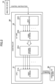
- FIG. 1 is a diagram for illustrating an example of an overall configuration of the production system.
- a production system 1 includes an analysis device 10, a controller 20, and a controlled device 30.
- the analysis device 10 and the controller 20 are connected to each other through a general network, for example, an Ethernet (trademark).
- the controller 20 and the controlled device 30 are connected to each other through a network for industrial machines.
- the network for connecting machines to each other is not limited to the example of this embodiment, and can be connected to each other through any network.
- the analysis device 10 is an example of an external device. Accordingly, the term "analysis device 10" as used in this embodiment can be read as "external device.”
- the external device is a device different from an industrial machine described later.
- the external device is communicatively connected to the industrial machine through the network.
- the external device is configured to collect data relating to the operation of the industrial machine.
- the external device is configured to analyze the operation of the industrial machine.
- the external device is configured to transmit a control command corresponding to the analysis result to the industrial machine.
- the analysis device 10 is a personal computer, a server computer, a cellular phone (including a smartphone), or a mobile terminal (including a tablet terminal).
- the analysis device 10 may be a kind of the industrial machines.
- the analysis device 10 includes a CPU 11, a storage 12, a communicator 13, an operation interface 14, and a display 15.
- the CPU 11 includes at least one processor.
- the storage 12 includes a RAM or a hard disk drive, and is configured to store various programs and data.
- the CPU 11 is configured to execute various types of processing based on those programs and data.
- the communicator 13 includes a network card and a communication interface, for example, various types of communication connectors, and is configured to communicate to/from other devices.
- the operation interface 14 is an input device such as a mouse and a keyboard.
- the display 15 is a liquid crystal display, an organic EL display, or the like, and is configured to display various types of screens in accordance with an instruction from the CPU 11.
- the controller 20 is an example of the industrial machine (first industrial machine). Accordingly, the term “controller 20" as used in this embodiment can be read as "industrial machine (first industrial machine).”
- the industrial machine is a collective term for machines configured to assist or substitute human work and peripheral machines thereof.
- the controlled device 30 also corresponds to the industrial machine.
- the controller 20 is configured to control at least one controlled device 30.
- the production system 1 may be referred to as "cell,” which is a unit smaller than a line. In this case, the controller 20 may be referred to as "cell controller.”
- the controller 20 includes a CPU 21, an Internet-of-Things (IoT) unit 22, a fourth storage 23, and a second communicator 24.
- the physical configuration of each of the CPU 21, the fourth storage 23, and the second communicator 24 may be the same as that of the CPU 11, the storage 12, and the communicator 13, respectively.
- the CPU 21 includes a first storage 21A.
- the first storage 21A includes at least one of a volatile memory or a nonvolatile memory.
- the first storage 21A may include a memory called "cache memory.”
- the first storage 21A stores a variable described later.
- the CPU 21 is an example of a first control circuit. Accordingly, the CPU 21 as used in this embodiment can be read as "first control circuit.”
- the first control circuit is configured to control another industrial machine described later based on each of a plurality of variables described later.
- the first control circuit is not limited to a general-purpose processor, and may be any circuit.
- the first control circuit may be a circuit called "FPGA” or "ASIC.”
- the first control circuit is a kind of circuitry.
- the IoT unit 22 is an example of a second control circuit. Accordingly, the IoT unit 22 as used in this embodiment can be read as "second control circuit.”
- the second control circuit is a circuit configured to receive a control command.
- the second control circuit is not limited to the circuit used for IoT, and may be any circuit.
- the second control circuit may be a circuit called "FPGA" or "ASIC.”
- the second control circuit may be a general-purpose processor.
- the second control circuit is a kind of circuitry.
- the IoT unit 22 is configured to transmit data to another computer through the network.
- the IoT unit 22 includes a second storage 22A, a third storage 22B, and a first communicator 22C.
- the second storage 22A and the third storage 22B may each be the same as the storage 12.
- the first communicator 22C may be the same as the communicator 13.
- the first communicator 22C is mainly used for communication to/from the analysis device 10, and the second communicator 24 is mainly used for controlling the controlled device 30.
- the IoT unit 22 may include another configuration, for example, a CPU. When the CPU 21 is provided with a data collection function, the IoT unit 22 may be omitted.
- the controlled device 30 is an example of another industrial machine (second industrial machine). Accordingly, the controller 20 as used in this embodiment can be read as "another industrial machine (second industrial machine) .”
- the term "industrial machine” has such a meaning as described above.
- the another industrial machine may be any kind of industrial machine described above.
- another industrial machine is controlled by the controller 20. It suffices that another industrial machine is an industrial machine different from the controller 20.
- the controlled device 30 includes a CPU 31, a storage 32, and a communicator 33.
- the physical configuration of each of the CPU 31, the storage 32, and the communicator 33 may be the same as that of each of the CPU 11, the storage 12, and the communicator 13, respectively.
- the controlled device 30 may also include other physical components.
- the controlled device 30 may include a circuit referred to as "FPGA" or "ASIC.”
- a machine to be controlled such as a motor or the like, a sensor for detecting an operation of a motor, a camera for photographing a state of a workpiece to be processed, an input/output device, or another industrial machine may be connected to the controlled device 30.
- the number of controlled devices 30 to be controlled by the controller 20 may be any number.
- the controller 20 may control only one device, or may control two or more devices.
- each of the analysis device 10, the controller 20, and the controlled device 30 may be supplied through the network.
- the hardware configuration of each device is not limited to the above-mentioned example, and various types of hardware can be applied.
- a reader for example, optical disc drive or memory card slot
- an input/output device for example, USB terminal
- programs and data stored in the information storage medium may be supplied through the reader or the input/output device.
- the controller 20 is configured to control the controlled device 30 based on each of the plurality of variables.
- the variable is referred to by a control program for controlling the controlled device 30.
- the control program may also rewrite the variable.
- the variable indicates a result of unfinished calculation or a physical quantity detected by a sensor (for example, a torque value detected by a torque sensor or a rotation speed of a motor detected by a motor encoder).
- the variable may be a value relating to an operation of the controlled device 30, and may be a value of, for example, a position or a moving speed of a robot arm, a speed of the motor, or a waiting time for waiting for the operation.
- the controlled device 30 executes a plurality of processes in a predetermined order
- an execution order of the processes is described in the control program.
- the controller 20 sends an instruction to the controlled device 30 based on the control program.
- the variable may be used as an execution condition of the process.
- the controlled device 30 stores a variable for starting the process, a variable for suspending the process, or a variable for ending the process.
- the variable may be referred to as "input/output variable.”
- the "process” is a task or an operation to be performed by the controlled device 30.
- the process may be composed of only one task, or may be composed of a combination of a plurality of tasks.
- the process may have any content in accordance with the use of the controlled device 30.
- the process is recognition of a workpiece, gripping of a workpiece, opening/closing of a door, setting of a workpiece, or machining using a machine tool.
- the controlled device 30 performs at least one process.
- the number of processes to be performed by the controlled device 30 may be any number.
- the controlled device 30 may perform only one process, or may perform a plurality of processes.
- the controlled device 30 performs the process based on the instruction received from the controller 20 and a device program stored in the controlled device 30 itself.
- the device program is a program defining an operation of the controlled device 30.
- each procedure of each process is defined.
- the device program can be created in any language in accordance with the controlled device 30, and is created in, for example, a ladder language or a robot language.
- a device program is prepared for each process. Accordingly, when a certain controlled device 30 is to perform "n" processes ("n" is a natural number), the controlled device 30 stores at least "n” device programs.
- the user of the controller 20 defines a variable and creates a control program
- the user of the analysis device 10 may not be familiar with contents of the variable and the control program. Accordingly, some variables are preferred not to be rewritten by the control command sent from the analysis device 10.
- variables that can be rewritten by the control command sent from the analysis device 10 are defined.
- Such a definition is hereinafter referred to as "variable definition.”
- the variables defined in the variable definition can also be said to be variables disclosed to the user of the analysis device 10.
- the user of the analysis device 10 can collect the variables defined in the variable definition.
- the user of the analysis device 10 may collect all the variables defined in the variable definition, or may collect only a part thereof.
- Variables that can be rewritten by the control command sent from the analysis device 10 are distinguished from variables that cannot be rewritten by the control command sent from the analysis device 10 based on the variable definition.
- the variable definition is created by the user of the controller 20.
- FIG. 2 is a diagram for illustrating a flow of processing for rewriting a value of the variable.
- the analysis device 10 is configured to transmit the control command to the controller 20.
- the control command is a command to be sent to the controller 20 from the analysis device 10, and can include any content.
- the control command is a command for rewriting at least one of the variables defined in the variable definition.
- the control command may be a command having a fixed cycle, or may be a command not particularly having a fixed cycle.
- a command functioning as feedback by the analysis device 10 is an example of the control command.
- the control command is not limited to the command functioning as feedback.
- the control command has a data format defined in advance, and its data length may be fixed or variable.
- the control command includes a name of a variable to be rewritten and its value.
- the analysis device 10 analyzes the values of the variables collected from the controller 20, and transmits the control command corresponding to its analysis result.
- the control command is transmitted to the first communicator 22C of the IoT unit 22.
- the first communicator 22C When the first communicator 22C starts to receive the control command, the first communicator 22C writes the name of the received variable and its value to the third storage 22B.
- the name of the variable may not be written to the third storage 22B, and its value may be written to a register corresponding to the name of the variable. This point is the same when the value of the variable is written to the first storage 21A and the second storage 22A which are described later.
- the analysis device 10 finishes transmitting the control command, the analysis device 10 transmits a predetermined completion notification to the controller 20.
- the first communicator 22C continues receiving the control command until the completion notification is received, and hence the names of the received variables and their values are written to the third storage 22B.
- the writing of all the variables included in the control command to the third storage 22B is completed.
- the IoT unit 22 writes the variable written in the third storage 22B to the second storage 22A.
- the third storage 22B serves as a buffer for temporarily holding the value of the variable included in the control command.
- the variables stored in the first storage 21A and the variables stored in the second storage 22A are periodically (regularly) matched with each other. Those variables also include variables other than the variables included in the control command.
- the first storage 21A also stores a variable that is not defined in the variable definition (variable that is not disclosed to the user of the analysis device 10). This variable can also be said to be a variable for controlling the controlled device 30.
- variable written in the third storage 22B is written to the second storage 22A before the matching of the variables between the first storage 21A and the second storage 22A is completed (that is, while those variables are being matched with each other), the value of the variable to be included in the control command may not be accurately reflected.
- a plurality of variables are subjected to the matching in a predetermined order. It is assumed that the variable that has already been subjected to the matching in one cycle period is written from the third storage 22B to the second storage 22A before the matching in that cycle period is completed. This variable is no longer subjected to the matching in that cycle period, and hence even when a value is written to the second storage 22A, this value is to be reflected in the first storage 21A in the next cycle period. Meanwhile, the variables that have not been subjected to the matching yet are reflected in the first storage 21A in the current cycle period. In this case, the plurality of variables to be simultaneously reflected are reflected in mutually different cycle periods, and hence accurate reflection cannot be performed.
- the variable is written from the third storage 22B to the second storage 22A immediately before the end of one cycle period.
- the variables written in the second storage 22A are written to the first storage 21A in the next cycle period.
- the CPU 21 controls the controlled device 30 based on the variables written in the first storage 21A.
- the production system 1 rewrites at least one of the variables defined in the variable definition in accordance with the control command sent to the controller 20 from the analysis device 10, to thereby quickly and accurately execute the control command directed to the controller 20. This configuration is described below in detail.
- FIG. 3 is a functional block diagram for illustrating functions to be implemented in the production system 1. In this embodiment, functions to be implemented in each of the analysis device 10, the controller 20, and the controlled device 30 are described.
- the analysis device 10 includes a data storage 100, an analysis module 101, a determination module 102, an input module 103, and a transmission module 104.
- the data storage 100 is mainly implemented by the storage 12.
- the data storage 100 is configured to store data required for transmitting a control command.
- the data storage 100 stores the collected data storing the variables collected from the controller 20.
- the collected data is data storing the values of the variables defined in the variable definition.
- the collected data may store the value of a variable at a certain time point, or may store a chronological change of the value of the variable.
- the collected data may store only the value of one variable, or may store the values of a plurality of variables.
- the collected data may store values calculated based on the values of a plurality of variables.
- the data storage 100 stores an application for analyzing the operation of the controller 20 or the controlled device 30.
- this application uses the collected data as input, and outputs the analysis result.
- a relationship between the collected data and the analysis result is defined in the application.
- the analysis result includes the contents of the control command.
- the analysis result includes the name of a variable having a value to be changed by the control command and the value.
- the application can also be expressed as a program for determining a type of a variable having a value to be changed and the value.
- the data stored in the data storage 100 is not limited to the above-mentioned example.
- the data storage 100 may store data indicating a variable to be collected for the collected data among the variables defined in the variable definition.
- the variables to be collected are specified by the user of the analysis device 10.
- the analysis device 10 collects the variables to be collected from the controller 20, and records the variables in the data storage 100 as collected data.
- the analysis module 101 is mainly implemented by the CPU 11.
- the analysis module 101 is configured to analyze the operation of at least one of the controller 20 or the controlled device 30.
- the analysis module 101 may analyze the operations of both the controller 20 and the controlled device 30, or may analyze the operation of any one of the controller 20 and the controlled device 30.
- the analysis of the operation refers to "analyzing the collected data.”
- the analysis module 101 performs the analysis by determining whether or not the collected data satisfies a predetermined condition.
- the predetermined condition is a condition that can be determined based on the collected data, and is, for example, whether or not a value indicated by the collected data is equal to or larger than a threshold value, or whether or not a value calculated based on the collected data is equal to or larger than a threshold value. For example, determining whether or not an abnormality has occurred in the operation corresponds to the analysis. Further, for example, determining whether or not it is required to change the value of the variable, a parameter, or firmware although no abnormality has occurred in the operation, corresponds to the analysis.
- the analysis is performed by the application, and hence the analysis module 101 inputs the variables presented in the collected data to the application, and uses the application to analyze the operation.
- the analysis module 101 uses the application to acquire the contents of the control command.
- the contents of the control command include the name of the variable to be rewritten by the control command and its value.
- the contents of the control command may include other contents, for example, a command to be executed by the controller 20 or the controlled device 30, parameters to be changed and their values, or firmware to be changed.
- the determination module 102 is mainly implemented by the CPU 11.
- the determination module 102 is configured to determine whether or not an input condition of the control command is satisfied based on the operation of at least one of the controller 20 or the controlled device 30.
- the determination module 102 may determine whether or not the input condition is satisfied based on the operations of both the controller 20 and the controlled device 30, or may be determine whether or not the input condition is satisfied based on the operation of any one of the controller 20 and the controlled device 30.
- the input condition is a condition for determining whether or not to input the control command.
- the input condition may be any condition.
- the input condition may be a condition irrelevant to the collected data, and may be a condition of, for example, a signal of a sensor directly connected to the analysis device 10, a state of a subject (for example, a workpiece) presented in an image acquired by a camera (vision sensor), or a current date/time.
- the determination module 102 determines whether or not the input condition is satisfied based on the collected data.
- the determination module 102 determines whether or not the value of the variable included in the collected data is within a predetermined range.
- the value of the variable being equal to or larger than a threshold value or the value of the variable being smaller than the threshold value corresponds to the value being within a predetermined range.
- the determination module 102 determines whether or not the number of times that the value of the variable included in the collected data is within the predetermined range is equal to or larger than a predetermined number of times.
- the determination module 102 may determine whether or not the value calculated based on the collected data is equal to or larger than a threshold value, or whether or not the number of times that the value is equal to or larger than a threshold value is equal to or larger than a predetermined number of times.
- the input module 103 is mainly implemented by the CPU 11.
- the input module 103 is configured to input, to the controller 20, the control command relating to the operation of at least one of the controller 20 or the controlled device 30.
- the control command may be a command relating to the operation of both the controller 20 and the controlled device 30, or may be a command relating to the operation of any one of the controller 20 and the controlled device 30.
- the input as used herein has the same meaning as that of the transmission.
- the operation of at least one of the controller 20 or the controlled device 30 can be identified by the collected data collected from the controller 20, and hence the input module 103 inputs the control command corresponding to the collected data.
- the input module 103 inputs the control command corresponding to the other data.
- the other data may be any data.
- the other data may be physical quantity data (instantaneous value data) detected by a sensor such as a torque sensor or a motor encoder, or trace data storing those physical quantities in time series.
- the input module 103 transmits, to the controller 20, the control command having the contents determined based on the collected data.
- the contents of the control command are determined by an application for analysis, and hence the input module 103 transmits, to the controller 20, the control command indicating the contents output by the analysis module 101.
- the type of the variable to be rewritten by the control command and its value are determined based on the contents of the collected data. The type and the value may be determined by, for example, the input module 103 or the analysis module 101.
- the input module 103 inputs a control command to the controller 20 when it is determined that the input condition is satisfied. When it is not determined that the input condition is satisfied, the control command is not input. In other words, the input module 103 inputs the control command to the controller 20 in response to the determination that the input condition is satisfied. The input module 103 waits to input the control command until the input condition is satisfied.
- the input module 103 inputs the control command based on the analysis result of the analysis module 101. For example, the input module 103 determines whether or not to transmit the control command based on the analysis result of the analysis module 101. The input module 103 transmits the control command when the analysis result is a predetermined result. In this case, the contents of the control command may be determined based on the collected data, or may be a fixed value irrespective of the collected data. Further, for example, the input module 103 inputs the control command having the contents corresponding to the analysis result of the analysis module 101. In this case, the name of the variable and its value that are included in the control command are determined by the analysis result.
- the transmission module 104 is mainly implemented by the CPU 11.
- the transmission module 104 is configured to transmit a predetermined completion notification to the controller 20 when the input of the control command is completed. When the input of the control command is not completed, the completion notification is not to be transmitted.
- the transmission module 104 transmits the completion notification to the controller 20 in response to the completion of the input of the control command.
- the completion of the input of the control command occurs at a time point at which the analysis device 10 completes transmitting the control command, a time point at which the controller 20 completes receiving the control command, a time point at which the value of the variable included in the control command is written to the third storage 22B, or a time point after those time points.
- the completion notification is a notification indicating that the input of the control command is completed. It suffices that the completion notification is data having a predetermined format, and the completion notification includes identification information indicating that the data is a completion notification. For example, the transmission module 104 determines whether or not the input has been performed up to the last data section of the control command. The transmission module 104 transmits the completion notification when the transmission module 104 determines that the input has been performed up to the last data section. The transmission module 104 waits to transmit the completion notification until the input has been completed up to the last data section.
- a first data storage 200 As illustrated in FIG. 3 , in the controller 20, a first data storage 200, a second data storage 201, a third data storage 202, a fourth data storage 203, a rewriting module 204, a determination module 205, and an operation control module 206 are implemented.
- the first data storage 200 is mainly implemented by the first storage 21A of the CPU 21.
- the first data storage 200 is configured to store data required for controlling the controlled device 30.
- the first data storage 200 stores variable definition data D1 indicating the variable definition and variable value data D2 indicating each of the plurality of variables.
- FIG. 4 is a table for showing a data storage example of variable definition data.
- the variable definition data D1 includes information for identifying a rewritable variable.
- the variable definition data D1 stores the name of the rewritable variable and a comment of the variable.
- the name of the variable is an example of the information for identifying the variable, and the variable may be identified not only by the name but also by an ID or other information.
- the comment is any character string input by the user of the controller 20, and presents information including the content and usage indicated by the variable.
- the variable definition data D1 is not limited to the example of FIG. 4 , and may be configured to store a list of all variables and a flag indicating whether or not each variable can be rewritten. In this case, the value of the flag is specified by the user of the controller 20.
- FIG. 5 is a table for showing a data storage example of variable value data.
- the variable value data D2 is data indicating a current value of each variable.
- the variable value data D2 presents the current value of each variable.
- Each variable is stored in a specific register. It is assumed that a relationship between each variable and each register (which variable is stored in which register) is specified in advance by, for example, a creator of the control program.
- the variables stored in the registers can be referred to as appropriate by another device (for example, the controller 20).
- the second data storage 201 is mainly implemented by the second storage 22A.
- the second data storage 201 is configured to store each of the plurality of variables.
- the second data storage 201 stores the same data as the variable value data D2.
- the second data storage 201 is regularly subjected to the matching with respect to the first data storage 200.
- the matching is to cause any one of the value stored in the first data storage 200 and the value stored in the second data storage 201 to agree with the other (to copy one value to the other). For example, changing the value stored in the first data storage 200 to the value stored in the second data storage 201 for a variable having a given variable name corresponds to the matching. In regard to the variable to be rewritten, the value stored in the first data storage 200 is changed to the value stored in the second data storage 201.
- changing the value stored in the second data storage 201 to the value stored in the first data storage 200 for a variable having a given variable name corresponds to the matching.
- the value stored in the second data storage 201 is changed to the value stored in the first data storage 200.
- the variables stored in the first data storage 200 are transmitted to the analysis device 10 via the second data storage 201.
- the term “regularly” has the same meaning as “periodically.”
- the variables stored in the first data storage 200 and the variables stored in the second data storage 201 are matched with each other.
- the matching may be executed mainly by the CPU 21 or may be executed mainly by the IoT unit 22.
- the CPU 21 or the IoT unit 22 matches the variables stored in the first data storage 200 and the variables stored in the second data storage 201 for each cycle period with each other.
- variable defined in the variable definition can be a target of the rewriting, and hence the variable stored in the second data storage 201 is copied to the first data storage 200. Consequently, the variable value data D2 of the first data storage 200 is replaced (overwritten) by the latest variable value data D2 of the second data storage 201. Only a part of the contents of the variable value data D2 stored in the second data storage 201 may be copied. For example, only the value of the variable to be rewritten may be copied.
- the third data storage 202 is mainly implemented by the third storage 22B.
- the third data storage 202 is configured to store at least one variable corresponding to the control command.
- the third data storage 202 stores the value of the variable included in the control command.
- the control command includes only the value of one variable
- the third data storage 202 stores only the value of one variable.
- the control command includes the values of a plurality of variables
- the third data storage 202 stores only the values of the plurality of variables.
- the controller 20 receives the control command via the first communicator 22C, and hence the third data storage 202 stores the variable included in the control command received via the first communicator 22C.
- the variable stored in the third data storage 202 is written to the second data storage 201, and hence the third data storage 202 temporarily stores the variable included in the control command.
- the variable stored in the third data storage 202 may be deleted when the variable is written to the second data storage 201, or may be held until the next control command is input.
- the fourth data storage 203 is mainly implemented by the fourth storage 23.
- the fourth data storage 203 is configured to store the data required for controlling the controlled device 30.
- the fourth data storage 203 stores the control program and parameters.
- the fourth data storage 203 may store firmware or another program, or may store a program for transmitting the collected data to the analysis device 10.
- the data stored in the controller 20 is not limited to the above-mentioned example.
- the controller 20 may store register definition data for defining a register corresponding to each variable.
- the controller 20 may store information enabling identification of the controlled device 30 to be controlled by the controller 20 itself.
- the controller 20 may store information enabling identification of the analysis device 10. Those pieces of data may be stored in any one of the first data storage 200, the second data storage 201, the third data storage 202, and the fourth data storage 203.
- the rewriting module 204 is mainly implemented by the IoT unit 22. That is, the IoT unit 22 includes the rewriting module 204.
- the rewriting module 204 is configured to rewrite at least one variable defined as a rewritable variable among the plurality of variables based on the control command.
- the control command is input by the analysis device 10 being an external device, and hence the rewriting module 204 rewrites at least one variable based on the control command input from the analysis device 10.
- the rewriting module 204 rewrites the value of the variable having the name included in the control command into the value included in the control command.
- the variable that is not defined in the variable definition is not subjected to the rewriting.
- the "rewriting" has the same meaning as overwriting, updating, or transferring. Changing the value stored in the memory to the value included in the control command corresponds to the rewriting.
- the rewriting module 204 may restrict the rewriting of the value of the variable.
- the rewriting module 204 refers to the variable definition data D1 to determine whether or not the variable included in the control command is a rewritable variable.
- the rewriting module 204 determines that the variable included in the control command is a rewritable variable
- the rewriting module 204 rewrites the value of the variable.
- the rewriting module 204 does not determine that the variable included in the control command is a rewritable variable
- the rewriting module 204 does not rewrite the value of the variable.
- the rewriting module 204 writes at least one variable stored in the third data storage 202 to the second data storage 201, and writes the at least one variable written in the second data storage 201 to the first data storage 200.
- the rewriting module 204 writes the at least one variable stored in the third data storage 202 to the first data storage 200 via (through intermediation of) the second data storage 201.
- the rewriting module 204 determines whether or not the writing of at least one variable to the third data storage 202 in accordance with the control command is completed. The rewriting module 204 determines whether or not all of at least one variable corresponding to the control command have been written to the third data storage 202. For example, when the rewriting module 204 receives the completion notification, the rewriting module 204 determines that the writing of at least one variable corresponding to the control command to the third data storage 202 is completed.
- the rewriting module 204 determines that the writing to the third data storage 202 is completed, the rewriting module 204 starts to write at least one variable written in the third data storage 202 to the second data storage 201.
- the rewriting module 204 does not start the writing.
- the rewriting module 204 starts to write in response to the determination that the writing to the third data storage 202 is completed. That is, the rewriting module 204 waits to perform the writing until the rewriting module 204 determines that the writing to the third data storage 202 is completed.
- the rewriting module 204 When it is determined that the matching between the first data storage 200 and the second data storage 201 has been performed, the rewriting module 204 writes the variable written in the third data storage 202 to the second data storage 201. When it is not determined that the matching has been performed, the rewriting module 204 does not start the writing. The rewriting module 204 starts the writing in response to the determination that the matching has been performed. That is, the rewriting module 204 waits to perform the writing until it is determined that the matching has been performed.
- the determination module 205 is mainly implemented by the IoT unit 22.
- the determination module 205 is configured to determine whether or not the matching has been performed between the first data storage 200 and the second data storage 201.
- the matching is periodically performed between the first data storage 200 and the second data storage 201, and the matching is completed immediately before one cycle period ends. Accordingly, the determination module 205 determines whether or not a time point immediately before one cycle period ends has arrived. It suffices that this time point is a time point a predetermined time before an end time point of one cycle period (a time point a predetermined time period after a start time point of one cycle period).
- the determination module 205 may determine whether or not the time point T/10 microseconds before the end time point of one cycle period has arrived. It suffices that a period from this time point until the end time point of one cycle period is set to have such a length enough to enable processing for writing the value of the variable stored in the third data storage 202 to the second data storage 201 to be sufficiently completed. When this time point has arrived, the determination module 205 determines that the matching has been performed between the first data storage 200 and the second data storage 201.
- the determination method performed by the determination module 205 is not limited to the above-mentioned example. For example, when the matching of a plurality of variables is performed in order, the determination module 205 may determine whether or not the matching has been completed up to the last variable. Further, for example, when a predetermined notification is transmitted from the CPU 21 to the IoT unit 22 at a time of completion of the matching of the variables, the determination module 205 may determine whether or not this notification has been received.
- the operation control module 206 is mainly implemented by the CPU 21.
- the operation control module 206 is configured to periodically update each of the plurality of variables to control the controlled device 30.
- the operation control module 206 controls the operation of the controlled device 30 based on the control program. For example, the operation control module 206 sends an instruction to the controlled device 30, and the controlled device 30 operates based on the instruction.
- the controlled device 30 operates based on the value of the variable associated with the device program, and hence, for example, the operation control module 206 sends, to the controlled device 30, an instruction to change the value of the variable for starting the device program.
- the controlled device 30 executes the device program by changing the value of the variable based on the instruction.
- the operation control module 206 may control the operation of the controlled device 30 by transmitting a command indicating the operation to be executed by the controlled device 30.
- a data storage 300 and a process execution module 301 are implemented.
- the data storage 300 is mainly implemented by the storage 32.
- the data storage 300 is configured to store the data required for the controlled device 30 to perform a predetermined operation.
- the data storage 300 stores the device program and current values of the variables.
- the current values of the variables are the same as the values stored in the variable value data D2.
- the data storage 300 also stores the values of variables other than variables defined in the variable definition. The value of each variable is stored in a register determined in advance.
- the process execution module 301 is mainly implemented by the CPU 31.
- the process execution module 301 is configured to execute a predetermined process based on the device program stored in the data storage 300 and an instruction received from the controller 20. For example, when the controller 20 is to start a certain device program, the controller 20 transmits to the controlled device 30 an instruction to set a variable associated with the device program to a predetermined value. When the controlled device 30 receives the instruction, the controlled device 30 changes the variable to a predetermined value. When the process execution module 301 detects that the variable has been changed to the predetermined value, the process execution module 301 executes the device program associated with the variable.
- the process execution module 301 changes the variable associated with the device program to a predetermined value, and transmits the fact to the controller 20. Then, when executing another device program, the controller 20 transmits to the controlled device 30 an instruction to set the variable associated with the another device program to a predetermined value, and the process execution module 301 executes the another device program.
- the execution order of a plurality of device programs is defined in the controlled device 30, it is not required to transmit the end of the device program to the controller 20, and the process execution module 301 may execute the plurality of device programs one after another.
- FIG. 6 is a flowchart for illustrating an example of processing to be executed in the production system 1.
- the processing illustrated in FIG. 6 is an example of the processing to be executed by the functional blocks illustrated in FIG. 3 .
- description is mainly given of processing relating to the control command, and processing to be performed by the controller 20 to control the controlled device 30 is omitted.
- the controller 20 transmits the collected data to the analysis device 10 (Step S1).
- Step S1 the controller 20 identifies variables to be collected based on the variable definition data D1 stored in the first storage 21A.
- the controller 20 refers to the variable value data D2 stored in the first storage 21A to generate collected data indicating the values of the variables to be collected.
- the controller 20 transmits the generated collected data to the analysis device 10.
- the analysis device 10 receives the collected data from the controller 20 (Step S2). In Step S2, the analysis device 10 records the received collected data in the storage 12.
- the collected data is referred to by the application for analysis.
- the application for analysis may be activated by an operation of the user of the analysis device 10, or may stay activated at all times.
- the collected data may be referred to by the application at any timing.
- the analysis device 10 analyzes the operation of the controller 20 or the controlled device 30 based on the application for analysis (Step S3).
- the analysis device 10 inputs the collected data to the application to execute the application.
- the application outputs the analysis result.
- the analysis device 10 determines whether or not the input condition of the control command is satisfied based on the analysis result obtained in Step S3 (Step S4). In Step S4, the analysis device 10 determines whether or not the analysis result indicating that the value of the variable is equal to or larger than the threshold value has been obtained.
- Step S4 When it is not determined that the input condition is satisfied (N in Step S4), the processing returns to Step S3. In this case, the input condition is not satisfied, and hence the control command is not transmitted. Meanwhile, when it is determined that the input condition is satisfied (Y in Step S4), the analysis device 10 determines the contents of the control command based on the analysis result (Step S5) . In Step S5, the analysis device 10 acquires the type of variable and its value that were determined by the application, and determines the type and the value as the contents of the control command.
- the analysis device 10 transmits the control command to the controller 20 (Step S6).
- Step S6 the analysis device 10 generates and transmits a control command including the name of the variable and its value that were determined in Step S5.
- the analysis device 10 determines whether or not the transmission of the control command is completed (Step S7).
- Step S7 the analysis device 10 determines whether or not the transmission has been completed up to the last data section (last packet) in the control command.
- Step S7 When it is not determined that the transmission of the control command is completed (N in Step S7), the processing returns to Step S6 to continue transmitting the control command. Meanwhile, when it is determined that the transmission of the control command is completed (Y in Step S7), the analysis device 10 transmits a predetermined completion notification to the controller 20 (Step S8).
- the controller 20 receives the control command via the first communicator 22C, and records, in the third storage 22B, the name of the variable and its value that are included in the control command (Step S9). In Step S9, each time the controller 20 receives a packet of the control command, the controller 20 records, in the third storage 22B, the name of the variable and its value that are included in the packet.
- the controller 20 determines whether or not the completion notification has been received (Step S10). When it is not determined that the completion notification has been received (N in Step S10), the processing returns to Step S9 to continue receiving the control command. Meanwhile, when it is determined that the completion notification has been received (Y in Step S10), the controller 20 determines whether or not the end time point of the cycle period for performing the matching of the variables between the first storage 21A and the second storage 22A is approaching (Step S11). For example, the controller 20 manages the time based on a timer value, and refers to the timer value to determine whether or not a time point a predetermined time before the end time point within one cycle period has arrived.
- Step S11 When it is not determined that the end time point of the cycle period is approaching (N in Step S11), the processing of Step S11 is executed again. In this case, even when the completion notification is received, the variable included in the control command is not to be written to the second storage 22A. Meanwhile, when it is determined that the end time point of the cycle period is approaching (Y in Step S11), the controller 20 writes the variable written in the third storage 22B to the second storage 22A (Step S12). The controller 20 waits to execute the processing of Step S12 until the determination performed in Step S11 becomes affirmative.
- Step S13 the controller 20 writes the variable written in the second storage 22A to the first storage 21A (Step S13), and this processing ends.
- the controller 20 controls the controlled device 30 based on the variable written in Step S13.
- At least one variable defined as a rewritable variable is rewritten based on the control command relating to the operation of at least one of the controller 20 or the controlled device 30.
- the contents of the control command can be quickly reflected in the value of the variable, and the control command directed to the controller 20 can be quickly executed.
- the rewritable variable is defined in advance by the control command, to thereby be able to prevent unintended rewriting of the variable and to accurately execute the control command directed to the controller 20.
- the quick and accurate execution of the control command can improve accuracy of the operation of the controlled device 30.
- the control command is input when the input condition is satisfied, that is, the control command is not regularly input (the control command is not always input). Consequently, a processing load on the controller 20 can be reduced.
- the CPU 21 being the first control circuit for controlling the controlled device 30 and the IoT unit 22 being the second control circuit for communicating to/from the outside are physically separated from each other, and hence it is possible to distribute the processing load and to prevent occurrences of problems in controlling the controlled device 30 and executing control commands. As a result, it is possible to improve the accuracy of control and to execute the control command directed to the controller 20 more quickly and accurately.
- At least one variable stored in the third storage 22B is written to the second storage 22A, and the at least one variable written in the second storage 22A is written to the first storage 21A, to thereby be able to accurately reflect at least one variable corresponding to the control command in the controller 20.
- the production system 1 starts to write the at least one variable written in the third storage 22B to the second storage 22A, to thereby be able to prevent the writing to the second storage 22A from being started before the writing of at least one variable included in the control command is completed and to execute the control command more accurately.
- the controller 20 when the controller 20 receives the completion notification, it is determined that the writing of at least one variable corresponding to the control command to the third storage 22B is completed, to thereby be able to accurately determine the completion of the writing and to execute the control command more accurately.
- the controller 20 can identify the completion of the writing by receiving the completion notification, and hence it is not required to constantly determine whether or not the writing is completed, to thereby be able to reduce the processing load on the controller 20.
- the production system 1 writes the variable written in the third storage 22B to the second storage 22A when it is determined that the matching has been performed between the first storage 21A and the second storage 22A, to thereby be able to execute the control command more accurately.
- the production system 1 can execute the control command corresponding to the analysis result quickly and accurately by inputting the control command based on the analysis result of the operation.
- the production system 1 can quickly and accurately execute the control command sent from the analysis device 10 being an external device.
- the controller 20 is no longer required to determine, for example, whether or not the control command is required to be transmitted, to thereby be able to reduce the processing load on the controller 20.
Description
- The present disclosure relates to a production system, a control method, and a program.
- In
WO 2015/068210 A1 , there is described a system configured to detect an operation of each of a plurality of industrial machines and upload trace data to a cloud server. In this system, the trace data is analyzed by an analyst. A user of the industrial machine is notified of an analysis result obtained by the analyst. The user of the industrial machine performs, for example, adjustment of parameters of the industrial machine based on the analysis result.
US 2019 0204803 A1 relates to a programmable logic controller system including a programmable logic controller and a peripheral instrument. In the Memory, an area in which writing of data associated with communication from an external instrument is prohibited separately from an area in which writing is enabled.
EP 3101497 A1 relates to a control system capable of sampling input and output signals by obtaining actual sampling data and variable sampling data and by generating time-series data and aligning the actual sampling data, the variable sampling data, and the output instruction data in the same time series to generate the single set of same time-series data. - An object to be achieved by one aspect of the present disclosure is to quickly and accurately execute, for example, a control command directed to an industrial machine.
The invention is defined by the features of the independent claims, the dependent claim define further advantageous embodiments. - According to one aspect of the present disclosure, there is provided a production system including: a first industrial machine configured to control a second industrial machine based on each of a plurality of variables; and an input module configured to input, to the first industrial machine, a control command relating to an operation of at least one of the first industrial machine or the second industrial machine, wherein the first industrial machine includes a rewriting module configured to rewrite, based on the control command, at least one variable defined as a rewritable variable among the plurality of variables.
- According to one aspect of the present disclosure, there is provided a control method including: inputting, to a first industrial machine configured to control a second industrial machine based on each of a plurality of variables, a control command relating to an operation of at least one of the first industrial machine or the second industrial machine; and rewriting, by the first industrial machine, based on the control command, at least one variable defined as a rewritable variable among the plurality of variables.
- According to one aspect of the present disclosure, there is provided a program for causing a first industrial machine configured to control a second industrial machine based on each of a plurality of variables to rewrite, based on a control command relating to an operation of at least one of the first industrial machine or the second industrial machine, at least one variable defined as a rewritable variable among the plurality of variables.
- According to one aspect of the present disclosure, the first industrial machine is configured to periodically update each of the plurality of variables to control the second industrial machine, the production system further includes a determination module configured to determine whether an input condition of the control command is satisfied based on the operation of at least one of the first industrial machine or the second industrial machine, and the input module is configured to input the control command to the first industrial machine when it is determined that the input condition is satisfied.
- According to one aspect of the present disclosure, the first industrial machine includes: a first control circuit configured to control the second industrial machine based on each of the plurality of variables; and a second control circuit configured to receive the control command, and the second control circuit includes the rewriting module.
- According to one aspect of the present disclosure, the first control circuit includes a first storage configured to store each of the plurality of variables, the second control circuit includes: a second storage configured to store each of the plurality of variables to have the each of the plurality of variables regularly subjected to matching with respect to the first storage; and a third storage configured to store the at least one variable corresponding to the control command, and the rewriting module is configured to: write the at least one variable stored in the third storage to the second storage; and write the at least one variable written in the second storage to the first storage.
- According to one aspect of the present disclosure, the rewriting module is configured to: determine whether the writing of the at least one variable corresponding to the control command to the third storage is completed; and start to write the at least one variable written in the third storage to the second storage when it is determined that the writing to the third storage is completed.
- According to one aspect of the present disclosure, the production system further includes a transmission module configured to transmit a predetermined completion notification to the first industrial machine when the input of the control command is completed, and the rewriting module is configured to determine, when the predetermined completion notification is received, that the writing of the at least one variable corresponding to the control command to the third storage is completed.
- According to one aspect of the present disclosure, the production system further includes a determination module configured to determine whether the matching has been performed between the first storage and the second storage, and the rewriting module is configured to write the variable written in the third storage to the second storage when it is determined that the matching has been performed between the first storage and the second storage.
- According to one aspect of the present disclosure, the production system further includes an analysis module configured to analyze the operation of at least one of the first industrial machine or the second industrial machine, and the input module is configured to input the control command based on an analysis result of the analysis module.
- According to one aspect of the present disclosure, the analysis module is configured to perform an analysis based on each of a plurality of applications, the input module is configured to input, based on an execution result of each of the plurality of applications, a control command including at least one variable associated with the each of the plurality of applications, and the rewriting module is configured to rewrite, based on the control command of the each of the plurality of applications, the at least one variable associated with the each of the plurality of applications.
- According to one aspect of the present disclosure, the production system further includes a restriction module configured to restrict simultaneous input of control commands of the plurality of applications.
- According to one aspect of the present disclosure, the production system further includes an external device different from the first industrial machine, the external device includes the input module, and the rewriting module is configured to rewrite the at least one variable based on the control command input from the external device.
- According to the above-mentioned invention, for example, it is possible to quickly and accurately execute the control command directed to the industrial machine.
-
-
FIG. 1 is a diagram for illustrating an example of an overall configuration of a production system according to an embodiment of the present disclosure. -
FIG. 2 is a diagram for illustrating a flow of processing for rewriting a value of a variable. -
FIG. 3 is a functional block diagram for illustrating functions to be implemented in the production system. -
FIG. 4 is a table for showing a data storage example of variable definition data. -
FIG. 5 is a table for showing a data storage example of variable value data. -
FIG. 6 is a flowchart for illustrating an example of processing to be executed in the production system. -
FIG. 7 is a functional block diagram in Modification Example (2) of the present disclosure. - In a technology for collecting data relating to an operation of an industrial machine, an analysis result is reflected in the industrial machine after an analysis is performed by an analyst, and hence it has required much time for the analysis result to be reflected. In addition, the analysis performed by the analyst may cause an error, and there has been a case in which the analysis is not performed accurately. As a result of extensive research and development for quickly and accurately executing a control command directed to the industrial machine, the inventors have conceived of a novel and original production system and the like. A detailed description is now given of the production system and the like according to an embodiment of the present disclosure.
-
FIG. 1 is a diagram for illustrating an example of an overall configuration of the production system. As illustrated inFIG. 1 , aproduction system 1 includes ananalysis device 10, acontroller 20, and a controlleddevice 30. In this embodiment, theanalysis device 10 and thecontroller 20 are connected to each other through a general network, for example, an Ethernet (trademark). Thecontroller 20 and the controlleddevice 30 are connected to each other through a network for industrial machines. The network for connecting machines to each other is not limited to the example of this embodiment, and can be connected to each other through any network. - The
analysis device 10 is an example of an external device. Accordingly, the term "analysis device 10" as used in this embodiment can be read as "external device." The external device is a device different from an industrial machine described later. The external device is communicatively connected to the industrial machine through the network. For example, the external device is configured to collect data relating to the operation of the industrial machine. In addition, for example, the external device is configured to analyze the operation of the industrial machine. In this embodiment, the external device is configured to transmit a control command corresponding to the analysis result to the industrial machine. - For example, the
analysis device 10 is a personal computer, a server computer, a cellular phone (including a smartphone), or a mobile terminal (including a tablet terminal). Theanalysis device 10 may be a kind of the industrial machines. Theanalysis device 10 includes aCPU 11, astorage 12, acommunicator 13, anoperation interface 14, and adisplay 15. - The
CPU 11 includes at least one processor. Thestorage 12 includes a RAM or a hard disk drive, and is configured to store various programs and data. TheCPU 11 is configured to execute various types of processing based on those programs and data. Thecommunicator 13 includes a network card and a communication interface, for example, various types of communication connectors, and is configured to communicate to/from other devices. Theoperation interface 14 is an input device such as a mouse and a keyboard. Thedisplay 15 is a liquid crystal display, an organic EL display, or the like, and is configured to display various types of screens in accordance with an instruction from theCPU 11. - The
controller 20 is an example of the industrial machine (first industrial machine). Accordingly, the term "controller 20" as used in this embodiment can be read as "industrial machine (first industrial machine)." The industrial machine is a collective term for machines configured to assist or substitute human work and peripheral machines thereof. For example, in addition to thecontroller 20, the controlleddevice 30 also corresponds to the industrial machine. For example, a programmable logic controller (PLC), a robot controller, an industrial robot, a motor controller, a servo amplifier, an inverter, a converter, a machine tool, a conveyance device, or a semiconductor manufacturing apparatus corresponds to the industrial machine. Thecontroller 20 is configured to control at least one controlleddevice 30. Theproduction system 1 may be referred to as "cell," which is a unit smaller than a line. In this case, thecontroller 20 may be referred to as "cell controller." - The
controller 20 includes aCPU 21, an Internet-of-Things (IoT)unit 22, afourth storage 23, and asecond communicator 24. The physical configuration of each of theCPU 21, thefourth storage 23, and thesecond communicator 24 may be the same as that of theCPU 11, thestorage 12, and thecommunicator 13, respectively. In this embodiment, theCPU 21 includes afirst storage 21A. Thefirst storage 21A includes at least one of a volatile memory or a nonvolatile memory. For example, thefirst storage 21A may include a memory called "cache memory." Thefirst storage 21A stores a variable described later. - The
CPU 21 is an example of a first control circuit. Accordingly, theCPU 21 as used in this embodiment can be read as "first control circuit." The first control circuit is configured to control another industrial machine described later based on each of a plurality of variables described later. The first control circuit is not limited to a general-purpose processor, and may be any circuit. For example, the first control circuit may be a circuit called "FPGA" or "ASIC." The first control circuit is a kind of circuitry. - The
IoT unit 22 is an example of a second control circuit. Accordingly, theIoT unit 22 as used in this embodiment can be read as "second control circuit." The second control circuit is a circuit configured to receive a control command. The second control circuit is not limited to the circuit used for IoT, and may be any circuit. For example, the second control circuit may be a circuit called "FPGA" or "ASIC." For example, the second control circuit may be a general-purpose processor. The second control circuit is a kind of circuitry. - The
IoT unit 22 is configured to transmit data to another computer through the network. For example, theIoT unit 22 includes asecond storage 22A, athird storage 22B, and afirst communicator 22C. Thesecond storage 22A and thethird storage 22B may each be the same as thestorage 12. Thefirst communicator 22C may be the same as thecommunicator 13. For example, thefirst communicator 22C is mainly used for communication to/from theanalysis device 10, and thesecond communicator 24 is mainly used for controlling the controlleddevice 30. TheIoT unit 22 may include another configuration, for example, a CPU. When theCPU 21 is provided with a data collection function, theIoT unit 22 may be omitted. - The controlled
device 30 is an example of another industrial machine (second industrial machine). Accordingly, thecontroller 20 as used in this embodiment can be read as "another industrial machine (second industrial machine) ." The term "industrial machine" has such a meaning as described above. The another industrial machine may be any kind of industrial machine described above. In this embodiment, another industrial machine is controlled by thecontroller 20. It suffices that another industrial machine is an industrial machine different from thecontroller 20. - The controlled
device 30 includes aCPU 31, astorage 32, and acommunicator 33. The physical configuration of each of theCPU 31, thestorage 32, and thecommunicator 33 may be the same as that of each of theCPU 11, thestorage 12, and thecommunicator 13, respectively. The controlleddevice 30 may also include other physical components. For example, the controlleddevice 30 may include a circuit referred to as "FPGA" or "ASIC." Further, for example, a machine to be controlled, such as a motor or the like, a sensor for detecting an operation of a motor, a camera for photographing a state of a workpiece to be processed, an input/output device, or another industrial machine may be connected to the controlleddevice 30. The number of controlleddevices 30 to be controlled by thecontroller 20 may be any number. For example, thecontroller 20 may control only one device, or may control two or more devices. - The programs and data described as being stored in each of the
analysis device 10, thecontroller 20, and the controlleddevice 30 may be supplied through the network. Moreover, the hardware configuration of each device is not limited to the above-mentioned example, and various types of hardware can be applied. For example, a reader (for example, optical disc drive or memory card slot) configured to read a computer-readable information storage medium and an input/output device (for example, USB terminal) configured to directly connect to an external device may be included. In this case, programs and data stored in the information storage medium may be supplied through the reader or the input/output device. - In this embodiment, the
controller 20 is configured to control the controlleddevice 30 based on each of the plurality of variables. The variable is referred to by a control program for controlling the controlleddevice 30. The control program may also rewrite the variable. For example, the variable indicates a result of unfinished calculation or a physical quantity detected by a sensor (for example, a torque value detected by a torque sensor or a rotation speed of a motor detected by a motor encoder). The variable may be a value relating to an operation of the controlleddevice 30, and may be a value of, for example, a position or a moving speed of a robot arm, a speed of the motor, or a waiting time for waiting for the operation. - For example, when the controlled
device 30 executes a plurality of processes in a predetermined order, an execution order of the processes is described in the control program. Thecontroller 20 sends an instruction to the controlleddevice 30 based on the control program. The variable may be used as an execution condition of the process. For example, the controlleddevice 30 stores a variable for starting the process, a variable for suspending the process, or a variable for ending the process. The variable may be referred to as "input/output variable." - The "process" is a task or an operation to be performed by the controlled
device 30. The process may be composed of only one task, or may be composed of a combination of a plurality of tasks. The process may have any content in accordance with the use of the controlleddevice 30. For example, the process is recognition of a workpiece, gripping of a workpiece, opening/closing of a door, setting of a workpiece, or machining using a machine tool. The controlleddevice 30 performs at least one process. The number of processes to be performed by the controlleddevice 30 may be any number. The controlleddevice 30 may perform only one process, or may perform a plurality of processes. The controlleddevice 30 performs the process based on the instruction received from thecontroller 20 and a device program stored in the controlleddevice 30 itself. - The device program is a program defining an operation of the controlled
device 30. In the device program, each procedure of each process is defined. The device program can be created in any language in accordance with the controlleddevice 30, and is created in, for example, a ladder language or a robot language. In this embodiment, a device program is prepared for each process. Accordingly, when a certain controlleddevice 30 is to perform "n" processes ("n" is a natural number), the controlleddevice 30 stores at least "n" device programs. - In this embodiment, description is given of a case in which a user of the
analysis device 10, a user of thecontroller 20, and a user of the controlleddevice 30 are different from one another. For example, when the user of thecontroller 20 defines a variable and creates a control program, the user of theanalysis device 10 may not be familiar with contents of the variable and the control program. Accordingly, some variables are preferred not to be rewritten by the control command sent from theanalysis device 10. - In view of this, in the
production system 1 according to this embodiment, of the plurality of variables, variables that can be rewritten by the control command sent from theanalysis device 10 are defined. Such a definition is hereinafter referred to as "variable definition." The variables defined in the variable definition can also be said to be variables disclosed to the user of theanalysis device 10. For example, the user of theanalysis device 10 can collect the variables defined in the variable definition. The user of theanalysis device 10 may collect all the variables defined in the variable definition, or may collect only a part thereof. Variables that can be rewritten by the control command sent from theanalysis device 10 are distinguished from variables that cannot be rewritten by the control command sent from theanalysis device 10 based on the variable definition. For example, the variable definition is created by the user of thecontroller 20. -
FIG. 2 is a diagram for illustrating a flow of processing for rewriting a value of the variable. As illustrated inFIG. 2 , theanalysis device 10 is configured to transmit the control command to thecontroller 20. The control command is a command to be sent to thecontroller 20 from theanalysis device 10, and can include any content. For example, the control command is a command for rewriting at least one of the variables defined in the variable definition. The control command may be a command having a fixed cycle, or may be a command not particularly having a fixed cycle. A command functioning as feedback by theanalysis device 10 is an example of the control command. The control command is not limited to the command functioning as feedback. The control command has a data format defined in advance, and its data length may be fixed or variable. The control command includes a name of a variable to be rewritten and its value. For example, theanalysis device 10 analyzes the values of the variables collected from thecontroller 20, and transmits the control command corresponding to its analysis result. The control command is transmitted to thefirst communicator 22C of theIoT unit 22. - When the
first communicator 22C starts to receive the control command, thefirst communicator 22C writes the name of the received variable and its value to thethird storage 22B. The name of the variable may not be written to thethird storage 22B, and its value may be written to a register corresponding to the name of the variable. This point is the same when the value of the variable is written to thefirst storage 21A and thesecond storage 22A which are described later. When theanalysis device 10 finishes transmitting the control command, theanalysis device 10 transmits a predetermined completion notification to thecontroller 20. Thefirst communicator 22C continues receiving the control command until the completion notification is received, and hence the names of the received variables and their values are written to thethird storage 22B. - When the
first communicator 22C receives the completion notification, the writing of all the variables included in the control command to thethird storage 22B is completed. When the writing of the variable to thethird storage 22B is completed, theIoT unit 22 writes the variable written in thethird storage 22B to thesecond storage 22A. Thethird storage 22B serves as a buffer for temporarily holding the value of the variable included in the control command. - In this embodiment, the variables stored in the
first storage 21A and the variables stored in thesecond storage 22A are periodically (regularly) matched with each other. Those variables also include variables other than the variables included in the control command. For example, thefirst storage 21A also stores a variable that is not defined in the variable definition (variable that is not disclosed to the user of the analysis device 10). This variable can also be said to be a variable for controlling the controlleddevice 30. - When the variable written in the
third storage 22B is written to thesecond storage 22A before the matching of the variables between thefirst storage 21A and thesecond storage 22A is completed (that is, while those variables are being matched with each other), the value of the variable to be included in the control command may not be accurately reflected. - For example, within one cycle period, a plurality of variables are subjected to the matching in a predetermined order. It is assumed that the variable that has already been subjected to the matching in one cycle period is written from the
third storage 22B to thesecond storage 22A before the matching in that cycle period is completed. This variable is no longer subjected to the matching in that cycle period, and hence even when a value is written to thesecond storage 22A, this value is to be reflected in thefirst storage 21A in the next cycle period. Meanwhile, the variables that have not been subjected to the matching yet are reflected in thefirst storage 21A in the current cycle period. In this case, the plurality of variables to be simultaneously reflected are reflected in mutually different cycle periods, and hence accurate reflection cannot be performed. - In this respect, it is highly possible that the matching of the variables between the
first storage 21A and thesecond storage 22A is completed immediately before the end of one cycle period. Accordingly, in this embodiment, the variable is written from thethird storage 22B to thesecond storage 22A immediately before the end of one cycle period. The variables written in thesecond storage 22A are written to thefirst storage 21A in the next cycle period. Thus, the variables included in the control command can be simultaneously reflected. TheCPU 21 controls the controlleddevice 30 based on the variables written in thefirst storage 21A. - As described above, the
production system 1 rewrites at least one of the variables defined in the variable definition in accordance with the control command sent to thecontroller 20 from theanalysis device 10, to thereby quickly and accurately execute the control command directed to thecontroller 20. This configuration is described below in detail. -
FIG. 3 is a functional block diagram for illustrating functions to be implemented in theproduction system 1. In this embodiment, functions to be implemented in each of theanalysis device 10, thecontroller 20, and the controlleddevice 30 are described. - As illustrated in
FIG. 3 , theanalysis device 10 includes adata storage 100, ananalysis module 101, adetermination module 102, aninput module 103, and atransmission module 104. - The
data storage 100 is mainly implemented by thestorage 12. Thedata storage 100 is configured to store data required for transmitting a control command. For example, thedata storage 100 stores the collected data storing the variables collected from thecontroller 20. The collected data is data storing the values of the variables defined in the variable definition. The collected data may store the value of a variable at a certain time point, or may store a chronological change of the value of the variable. In addition, the collected data may store only the value of one variable, or may store the values of a plurality of variables. In another example, the collected data may store values calculated based on the values of a plurality of variables. - In addition, for example, the
data storage 100 stores an application for analyzing the operation of thecontroller 20 or the controlleddevice 30. For example, this application uses the collected data as input, and outputs the analysis result. A relationship between the collected data and the analysis result is defined in the application. The analysis result includes the contents of the control command. For example, the analysis result includes the name of a variable having a value to be changed by the control command and the value. The application can also be expressed as a program for determining a type of a variable having a value to be changed and the value. - The data stored in the
data storage 100 is not limited to the above-mentioned example. For example, thedata storage 100 may store data indicating a variable to be collected for the collected data among the variables defined in the variable definition. The variables to be collected are specified by the user of theanalysis device 10. Theanalysis device 10 collects the variables to be collected from thecontroller 20, and records the variables in thedata storage 100 as collected data. - The
analysis module 101 is mainly implemented by theCPU 11. Theanalysis module 101 is configured to analyze the operation of at least one of thecontroller 20 or the controlleddevice 30. Theanalysis module 101 may analyze the operations of both thecontroller 20 and the controlleddevice 30, or may analyze the operation of any one of thecontroller 20 and the controlleddevice 30. - The analysis of the operation refers to "analyzing the collected data." The
analysis module 101 performs the analysis by determining whether or not the collected data satisfies a predetermined condition. The predetermined condition is a condition that can be determined based on the collected data, and is, for example, whether or not a value indicated by the collected data is equal to or larger than a threshold value, or whether or not a value calculated based on the collected data is equal to or larger than a threshold value. For example, determining whether or not an abnormality has occurred in the operation corresponds to the analysis. Further, for example, determining whether or not it is required to change the value of the variable, a parameter, or firmware although no abnormality has occurred in the operation, corresponds to the analysis. - In this embodiment, the analysis is performed by the application, and hence the
analysis module 101 inputs the variables presented in the collected data to the application, and uses the application to analyze the operation. For example, theanalysis module 101 uses the application to acquire the contents of the control command. The contents of the control command include the name of the variable to be rewritten by the control command and its value. The contents of the control command may include other contents, for example, a command to be executed by thecontroller 20 or the controlleddevice 30, parameters to be changed and their values, or firmware to be changed. - The
determination module 102 is mainly implemented by theCPU 11. Thedetermination module 102 is configured to determine whether or not an input condition of the control command is satisfied based on the operation of at least one of thecontroller 20 or the controlleddevice 30. Thedetermination module 102 may determine whether or not the input condition is satisfied based on the operations of both thecontroller 20 and the controlleddevice 30, or may be determine whether or not the input condition is satisfied based on the operation of any one of thecontroller 20 and the controlleddevice 30. - The input condition is a condition for determining whether or not to input the control command. In this embodiment, a case in which the input condition is a condition that can be determined based on the collected data is described, but the input condition may be any condition. For example, the input condition may be a condition irrelevant to the collected data, and may be a condition of, for example, a signal of a sensor directly connected to the
analysis device 10, a state of a subject (for example, a workpiece) presented in an image acquired by a camera (vision sensor), or a current date/time. - For example, the
determination module 102 determines whether or not the input condition is satisfied based on the collected data. Thedetermination module 102 determines whether or not the value of the variable included in the collected data is within a predetermined range. The value of the variable being equal to or larger than a threshold value or the value of the variable being smaller than the threshold value corresponds to the value being within a predetermined range. For example, thedetermination module 102 determines whether or not the number of times that the value of the variable included in the collected data is within the predetermined range is equal to or larger than a predetermined number of times. Further, for example, thedetermination module 102 may determine whether or not the value calculated based on the collected data is equal to or larger than a threshold value, or whether or not the number of times that the value is equal to or larger than a threshold value is equal to or larger than a predetermined number of times. - The
input module 103 is mainly implemented by theCPU 11. Theinput module 103 is configured to input, to thecontroller 20, the control command relating to the operation of at least one of thecontroller 20 or the controlleddevice 30. The control command may be a command relating to the operation of both thecontroller 20 and the controlleddevice 30, or may be a command relating to the operation of any one of thecontroller 20 and the controlleddevice 30. The input as used herein has the same meaning as that of the transmission. - In this embodiment, the operation of at least one of the
controller 20 or the controlleddevice 30 can be identified by the collected data collected from thecontroller 20, and hence theinput module 103 inputs the control command corresponding to the collected data. When the operation can be identified by data other than the collected data, theinput module 103 inputs the control command corresponding to the other data. The other data may be any data. For example, the other data may be physical quantity data (instantaneous value data) detected by a sensor such as a torque sensor or a motor encoder, or trace data storing those physical quantities in time series. - The
input module 103 transmits, to thecontroller 20, the control command having the contents determined based on the collected data. In this embodiment, the contents of the control command are determined by an application for analysis, and hence theinput module 103 transmits, to thecontroller 20, the control command indicating the contents output by theanalysis module 101. For example, the type of the variable to be rewritten by the control command and its value are determined based on the contents of the collected data. The type and the value may be determined by, for example, theinput module 103 or theanalysis module 101. - In this embodiment, the
input module 103 inputs a control command to thecontroller 20 when it is determined that the input condition is satisfied. When it is not determined that the input condition is satisfied, the control command is not input. In other words, theinput module 103 inputs the control command to thecontroller 20 in response to the determination that the input condition is satisfied. Theinput module 103 waits to input the control command until the input condition is satisfied. - In this embodiment, the
input module 103 inputs the control command based on the analysis result of theanalysis module 101. For example, theinput module 103 determines whether or not to transmit the control command based on the analysis result of theanalysis module 101. Theinput module 103 transmits the control command when the analysis result is a predetermined result. In this case, the contents of the control command may be determined based on the collected data, or may be a fixed value irrespective of the collected data. Further, for example, theinput module 103 inputs the control command having the contents corresponding to the analysis result of theanalysis module 101. In this case, the name of the variable and its value that are included in the control command are determined by the analysis result. - The
transmission module 104 is mainly implemented by theCPU 11. Thetransmission module 104 is configured to transmit a predetermined completion notification to thecontroller 20 when the input of the control command is completed. When the input of the control command is not completed, the completion notification is not to be transmitted. Thetransmission module 104 transmits the completion notification to thecontroller 20 in response to the completion of the input of the control command. - The completion of the input of the control command occurs at a time point at which the
analysis device 10 completes transmitting the control command, a time point at which thecontroller 20 completes receiving the control command, a time point at which the value of the variable included in the control command is written to thethird storage 22B, or a time point after those time points. - The completion notification is a notification indicating that the input of the control command is completed. It suffices that the completion notification is data having a predetermined format, and the completion notification includes identification information indicating that the data is a completion notification. For example, the
transmission module 104 determines whether or not the input has been performed up to the last data section of the control command. Thetransmission module 104 transmits the completion notification when thetransmission module 104 determines that the input has been performed up to the last data section. Thetransmission module 104 waits to transmit the completion notification until the input has been completed up to the last data section. - As illustrated in
FIG. 3 , in thecontroller 20, afirst data storage 200, asecond data storage 201, athird data storage 202, afourth data storage 203, arewriting module 204, adetermination module 205, and anoperation control module 206 are implemented. - The
first data storage 200 is mainly implemented by thefirst storage 21A of theCPU 21. Thefirst data storage 200 is configured to store data required for controlling the controlleddevice 30. For example, thefirst data storage 200 stores variable definition data D1 indicating the variable definition and variable value data D2 indicating each of the plurality of variables. -
FIG. 4 is a table for showing a data storage example of variable definition data. As shown inFIG. 4 , the variable definition data D1 includes information for identifying a rewritable variable. For example, the variable definition data D1 stores the name of the rewritable variable and a comment of the variable. The name of the variable is an example of the information for identifying the variable, and the variable may be identified not only by the name but also by an ID or other information. - The comment is any character string input by the user of the
controller 20, and presents information including the content and usage indicated by the variable. The variable definition data D1 is not limited to the example ofFIG. 4 , and may be configured to store a list of all variables and a flag indicating whether or not each variable can be rewritten. In this case, the value of the flag is specified by the user of thecontroller 20. -
FIG. 5 is a table for showing a data storage example of variable value data. As shown inFIG. 5 , the variable value data D2 is data indicating a current value of each variable. For example, the variable value data D2 presents the current value of each variable. Each variable is stored in a specific register. It is assumed that a relationship between each variable and each register (which variable is stored in which register) is specified in advance by, for example, a creator of the control program. The variables stored in the registers can be referred to as appropriate by another device (for example, the controller 20). - The
second data storage 201 is mainly implemented by thesecond storage 22A. Thesecond data storage 201 is configured to store each of the plurality of variables. Thesecond data storage 201 stores the same data as the variable value data D2. Thesecond data storage 201 is regularly subjected to the matching with respect to thefirst data storage 200. - The matching is to cause any one of the value stored in the
first data storage 200 and the value stored in thesecond data storage 201 to agree with the other (to copy one value to the other). For example, changing the value stored in thefirst data storage 200 to the value stored in thesecond data storage 201 for a variable having a given variable name corresponds to the matching. In regard to the variable to be rewritten, the value stored in thefirst data storage 200 is changed to the value stored in thesecond data storage 201. - Further, for example, changing the value stored in the
second data storage 201 to the value stored in thefirst data storage 200 for a variable having a given variable name corresponds to the matching. When the variable collected by theanalysis device 10 is recorded in thesecond data storage 201, the value stored in thesecond data storage 201 is changed to the value stored in thefirst data storage 200. Thus, the variables stored in thefirst data storage 200 are transmitted to theanalysis device 10 via thesecond data storage 201. - The term "regularly" has the same meaning as "periodically." For each cycle period, the variables stored in the
first data storage 200 and the variables stored in thesecond data storage 201 are matched with each other. The matching may be executed mainly by theCPU 21 or may be executed mainly by theIoT unit 22. TheCPU 21 or theIoT unit 22 matches the variables stored in thefirst data storage 200 and the variables stored in thesecond data storage 201 for each cycle period with each other. - For example, the variable defined in the variable definition can be a target of the rewriting, and hence the variable stored in the
second data storage 201 is copied to thefirst data storage 200. Consequently, the variable value data D2 of thefirst data storage 200 is replaced (overwritten) by the latest variable value data D2 of thesecond data storage 201. Only a part of the contents of the variable value data D2 stored in thesecond data storage 201 may be copied. For example, only the value of the variable to be rewritten may be copied. - The
third data storage 202 is mainly implemented by thethird storage 22B. Thethird data storage 202 is configured to store at least one variable corresponding to the control command. Thethird data storage 202 stores the value of the variable included in the control command. When the control command includes only the value of one variable, thethird data storage 202 stores only the value of one variable. When the control command includes the values of a plurality of variables, thethird data storage 202 stores only the values of the plurality of variables. - In this embodiment, the
controller 20 receives the control command via thefirst communicator 22C, and hence thethird data storage 202 stores the variable included in the control command received via thefirst communicator 22C. The variable stored in thethird data storage 202 is written to thesecond data storage 201, and hence thethird data storage 202 temporarily stores the variable included in the control command. The variable stored in thethird data storage 202 may be deleted when the variable is written to thesecond data storage 201, or may be held until the next control command is input. - The
fourth data storage 203 is mainly implemented by thefourth storage 23. Thefourth data storage 203 is configured to store the data required for controlling the controlleddevice 30. For example, thefourth data storage 203 stores the control program and parameters. Further, for example, thefourth data storage 203 may store firmware or another program, or may store a program for transmitting the collected data to theanalysis device 10. - The data stored in the
controller 20 is not limited to the above-mentioned example. For example, thecontroller 20 may store register definition data for defining a register corresponding to each variable. Further, for example, thecontroller 20 may store information enabling identification of the controlleddevice 30 to be controlled by thecontroller 20 itself. Further, for example, thecontroller 20 may store information enabling identification of theanalysis device 10. Those pieces of data may be stored in any one of thefirst data storage 200, thesecond data storage 201, thethird data storage 202, and thefourth data storage 203. - The
rewriting module 204 is mainly implemented by theIoT unit 22. That is, theIoT unit 22 includes therewriting module 204. Therewriting module 204 is configured to rewrite at least one variable defined as a rewritable variable among the plurality of variables based on the control command. In this embodiment, the control command is input by theanalysis device 10 being an external device, and hence therewriting module 204 rewrites at least one variable based on the control command input from theanalysis device 10. - The
rewriting module 204 rewrites the value of the variable having the name included in the control command into the value included in the control command. The variable that is not defined in the variable definition is not subjected to the rewriting. The "rewriting" has the same meaning as overwriting, updating, or transferring. Changing the value stored in the memory to the value included in the control command corresponds to the rewriting. - When the control command includes a variable that is not defined in the variable definition (a variable that is not rewritable), the
rewriting module 204 may restrict the rewriting of the value of the variable. In this case, therewriting module 204 refers to the variable definition data D1 to determine whether or not the variable included in the control command is a rewritable variable. When therewriting module 204 determines that the variable included in the control command is a rewritable variable, therewriting module 204 rewrites the value of the variable. When therewriting module 204 does not determine that the variable included in the control command is a rewritable variable, therewriting module 204 does not rewrite the value of the variable. - In this embodiment, the
rewriting module 204 writes at least one variable stored in thethird data storage 202 to thesecond data storage 201, and writes the at least one variable written in thesecond data storage 201 to thefirst data storage 200. Therewriting module 204 writes the at least one variable stored in thethird data storage 202 to thefirst data storage 200 via (through intermediation of) thesecond data storage 201. - For example, the
rewriting module 204 determines whether or not the writing of at least one variable to thethird data storage 202 in accordance with the control command is completed. Therewriting module 204 determines whether or not all of at least one variable corresponding to the control command have been written to thethird data storage 202. For example, when therewriting module 204 receives the completion notification, therewriting module 204 determines that the writing of at least one variable corresponding to the control command to thethird data storage 202 is completed. - When the
rewriting module 204 determines that the writing to thethird data storage 202 is completed, therewriting module 204 starts to write at least one variable written in thethird data storage 202 to thesecond data storage 201. When therewriting module 204 does not determine that the writing to thethird data storage 202 is completed, therewriting module 204 does not start the writing. Therewriting module 204 starts to write in response to the determination that the writing to thethird data storage 202 is completed. That is, therewriting module 204 waits to perform the writing until therewriting module 204 determines that the writing to thethird data storage 202 is completed. - When it is determined that the matching between the
first data storage 200 and thesecond data storage 201 has been performed, therewriting module 204 writes the variable written in thethird data storage 202 to thesecond data storage 201. When it is not determined that the matching has been performed, therewriting module 204 does not start the writing. Therewriting module 204 starts the writing in response to the determination that the matching has been performed. That is, therewriting module 204 waits to perform the writing until it is determined that the matching has been performed. - The
determination module 205 is mainly implemented by theIoT unit 22. Thedetermination module 205 is configured to determine whether or not the matching has been performed between thefirst data storage 200 and thesecond data storage 201. In this embodiment, the matching is periodically performed between thefirst data storage 200 and thesecond data storage 201, and the matching is completed immediately before one cycle period ends. Accordingly, thedetermination module 205 determines whether or not a time point immediately before one cycle period ends has arrived. It suffices that this time point is a time point a predetermined time before an end time point of one cycle period (a time point a predetermined time period after a start time point of one cycle period). - For example, assuming that one cycle period is T microseconds (where T is a positive number), the
determination module 205 may determine whether or not the time point T/10 microseconds before the end time point of one cycle period has arrived. It suffices that a period from this time point until the end time point of one cycle period is set to have such a length enough to enable processing for writing the value of the variable stored in thethird data storage 202 to thesecond data storage 201 to be sufficiently completed. When this time point has arrived, thedetermination module 205 determines that the matching has been performed between thefirst data storage 200 and thesecond data storage 201. - The determination method performed by the
determination module 205 is not limited to the above-mentioned example. For example, when the matching of a plurality of variables is performed in order, thedetermination module 205 may determine whether or not the matching has been completed up to the last variable. Further, for example, when a predetermined notification is transmitted from theCPU 21 to theIoT unit 22 at a time of completion of the matching of the variables, thedetermination module 205 may determine whether or not this notification has been received. - The
operation control module 206 is mainly implemented by theCPU 21. Theoperation control module 206 is configured to periodically update each of the plurality of variables to control the controlleddevice 30. Theoperation control module 206 controls the operation of the controlleddevice 30 based on the control program. For example, theoperation control module 206 sends an instruction to the controlleddevice 30, and the controlleddevice 30 operates based on the instruction. In this embodiment, the controlleddevice 30 operates based on the value of the variable associated with the device program, and hence, for example, theoperation control module 206 sends, to the controlleddevice 30, an instruction to change the value of the variable for starting the device program. The controlleddevice 30 executes the device program by changing the value of the variable based on the instruction. When the variable is not particularly used for controlling the operation of the controlleddevice 30, theoperation control module 206 may control the operation of the controlleddevice 30 by transmitting a command indicating the operation to be executed by the controlleddevice 30. - As illustrated in
FIG. 3 , in the controlleddevice 30, adata storage 300 and aprocess execution module 301 are implemented. - The
data storage 300 is mainly implemented by thestorage 32. Thedata storage 300 is configured to store the data required for the controlleddevice 30 to perform a predetermined operation. For example, thedata storage 300 stores the device program and current values of the variables. The current values of the variables are the same as the values stored in the variable value data D2. Thedata storage 300 also stores the values of variables other than variables defined in the variable definition. The value of each variable is stored in a register determined in advance. - The
process execution module 301 is mainly implemented by theCPU 31. Theprocess execution module 301 is configured to execute a predetermined process based on the device program stored in thedata storage 300 and an instruction received from thecontroller 20. For example, when thecontroller 20 is to start a certain device program, thecontroller 20 transmits to the controlleddevice 30 an instruction to set a variable associated with the device program to a predetermined value. When the controlleddevice 30 receives the instruction, the controlleddevice 30 changes the variable to a predetermined value. When theprocess execution module 301 detects that the variable has been changed to the predetermined value, theprocess execution module 301 executes the device program associated with the variable. - When the process indicated by the device program ends, the
process execution module 301 changes the variable associated with the device program to a predetermined value, and transmits the fact to thecontroller 20. Then, when executing another device program, thecontroller 20 transmits to the controlleddevice 30 an instruction to set the variable associated with the another device program to a predetermined value, and theprocess execution module 301 executes the another device program. When the execution order of a plurality of device programs is defined in the controlleddevice 30, it is not required to transmit the end of the device program to thecontroller 20, and theprocess execution module 301 may execute the plurality of device programs one after another. -
FIG. 6 is a flowchart for illustrating an example of processing to be executed in theproduction system 1. The processing illustrated inFIG. 6 is an example of the processing to be executed by the functional blocks illustrated inFIG. 3 . InFIG. 6 , description is mainly given of processing relating to the control command, and processing to be performed by thecontroller 20 to control the controlleddevice 30 is omitted. - As illustrated in
FIG. 6 , thecontroller 20 transmits the collected data to the analysis device 10 (Step S1). In Step S1, thecontroller 20 identifies variables to be collected based on the variable definition data D1 stored in thefirst storage 21A. Thecontroller 20 refers to the variable value data D2 stored in thefirst storage 21A to generate collected data indicating the values of the variables to be collected. Thecontroller 20 transmits the generated collected data to theanalysis device 10. - The
analysis device 10 receives the collected data from the controller 20 (Step S2). In Step S2, theanalysis device 10 records the received collected data in thestorage 12. The collected data is referred to by the application for analysis. The application for analysis may be activated by an operation of the user of theanalysis device 10, or may stay activated at all times. The collected data may be referred to by the application at any timing. - The
analysis device 10 analyzes the operation of thecontroller 20 or the controlleddevice 30 based on the application for analysis (Step S3). In Step S3, theanalysis device 10 inputs the collected data to the application to execute the application. The application outputs the analysis result. - The
analysis device 10 determines whether or not the input condition of the control command is satisfied based on the analysis result obtained in Step S3 (Step S4). In Step S4, theanalysis device 10 determines whether or not the analysis result indicating that the value of the variable is equal to or larger than the threshold value has been obtained. - When it is not determined that the input condition is satisfied (N in Step S4), the processing returns to Step S3. In this case, the input condition is not satisfied, and hence the control command is not transmitted. Meanwhile, when it is determined that the input condition is satisfied (Y in Step S4), the
analysis device 10 determines the contents of the control command based on the analysis result (Step S5) . In Step S5, theanalysis device 10 acquires the type of variable and its value that were determined by the application, and determines the type and the value as the contents of the control command. - The
analysis device 10 transmits the control command to the controller 20 (Step S6). In Step S6, theanalysis device 10 generates and transmits a control command including the name of the variable and its value that were determined in Step S5. Theanalysis device 10 determines whether or not the transmission of the control command is completed (Step S7). In Step S7, theanalysis device 10 determines whether or not the transmission has been completed up to the last data section (last packet) in the control command. - When it is not determined that the transmission of the control command is completed (N in Step S7), the processing returns to Step S6 to continue transmitting the control command. Meanwhile, when it is determined that the transmission of the control command is completed (Y in Step S7), the
analysis device 10 transmits a predetermined completion notification to the controller 20 (Step S8). - The
controller 20 receives the control command via thefirst communicator 22C, and records, in thethird storage 22B, the name of the variable and its value that are included in the control command (Step S9). In Step S9, each time thecontroller 20 receives a packet of the control command, thecontroller 20 records, in thethird storage 22B, the name of the variable and its value that are included in the packet. - The
controller 20 determines whether or not the completion notification has been received (Step S10). When it is not determined that the completion notification has been received (N in Step S10), the processing returns to Step S9 to continue receiving the control command. Meanwhile, when it is determined that the completion notification has been received (Y in Step S10), thecontroller 20 determines whether or not the end time point of the cycle period for performing the matching of the variables between thefirst storage 21A and thesecond storage 22A is approaching (Step S11). For example, thecontroller 20 manages the time based on a timer value, and refers to the timer value to determine whether or not a time point a predetermined time before the end time point within one cycle period has arrived. - When it is not determined that the end time point of the cycle period is approaching (N in Step S11), the processing of Step S11 is executed again. In this case, even when the completion notification is received, the variable included in the control command is not to be written to the
second storage 22A. Meanwhile, when it is determined that the end time point of the cycle period is approaching (Y in Step S11), thecontroller 20 writes the variable written in thethird storage 22B to thesecond storage 22A (Step S12). Thecontroller 20 waits to execute the processing of Step S12 until the determination performed in Step S11 becomes affirmative. - When the next cycle period arrives, the
controller 20 writes the variable written in thesecond storage 22A to thefirst storage 21A (Step S13), and this processing ends. Thecontroller 20 controls the controlleddevice 30 based on the variable written in Step S13. - With the
production system 1 described above, at least one variable defined as a rewritable variable is rewritten based on the control command relating to the operation of at least one of thecontroller 20 or the controlleddevice 30. Thus, the contents of the control command can be quickly reflected in the value of the variable, and the control command directed to thecontroller 20 can be quickly executed. In addition, the rewritable variable is defined in advance by the control command, to thereby be able to prevent unintended rewriting of the variable and to accurately execute the control command directed to thecontroller 20. The quick and accurate execution of the control command can improve accuracy of the operation of the controlleddevice 30. - In the
production system 1, the control command is input when the input condition is satisfied, that is, the control command is not regularly input (the control command is not always input). Consequently, a processing load on thecontroller 20 can be reduced. - In the
production system 1, theCPU 21 being the first control circuit for controlling the controlleddevice 30 and theIoT unit 22 being the second control circuit for communicating to/from the outside are physically separated from each other, and hence it is possible to distribute the processing load and to prevent occurrences of problems in controlling the controlleddevice 30 and executing control commands. As a result, it is possible to improve the accuracy of control and to execute the control command directed to thecontroller 20 more quickly and accurately. - In the
production system 1, at least one variable stored in thethird storage 22B is written to thesecond storage 22A, and the at least one variable written in thesecond storage 22A is written to thefirst storage 21A, to thereby be able to accurately reflect at least one variable corresponding to the control command in thecontroller 20. - When it is determined that the writing of at least one variable included in the control command to the
third storage 22B is completed, theproduction system 1 starts to write the at least one variable written in thethird storage 22B to thesecond storage 22A, to thereby be able to prevent the writing to thesecond storage 22A from being started before the writing of at least one variable included in the control command is completed and to execute the control command more accurately. - In the
production system 1, when thecontroller 20 receives the completion notification, it is determined that the writing of at least one variable corresponding to the control command to thethird storage 22B is completed, to thereby be able to accurately determine the completion of the writing and to execute the control command more accurately. In addition, thecontroller 20 can identify the completion of the writing by receiving the completion notification, and hence it is not required to constantly determine whether or not the writing is completed, to thereby be able to reduce the processing load on thecontroller 20. - The
production system 1 writes the variable written in thethird storage 22B to thesecond storage 22A when it is determined that the matching has been performed between thefirst storage 21A and thesecond storage 22A, to thereby be able to execute the control command more accurately. - The
production system 1 can execute the control command corresponding to the analysis result quickly and accurately by inputting the control command based on the analysis result of the operation. - The
production system 1 can quickly and accurately execute the control command sent from theanalysis device 10 being an external device. When roles are divided between theanalysis device 10 and thecontroller 20, thecontroller 20 is no longer required to determine, for example, whether or not the control command is required to be transmitted, to thereby be able to reduce the processing load on thecontroller 20.
Claims (8)
- A production system (1), comprising:a first industrial machine (20) configured to control a second industrial machine (30) based on each of a plurality of variables; andan input module (103) configured to input, to the first industrial machine (20), a control command relating to an operation of at least one of the first industrial machine (20) or the second industrial machine (30),wherein the first industrial machine (20) includes:a rewriting module (204) configured to rewrite, based on the control command, at least one variable defined as a rewritable variable among the plurality of variables;a first control circuit (21) configured to control the second industrial machine (30) based on each of the plurality of variables; anda second control circuit (22) configured to receive the control command,wherein the second control circuit (22) includes the rewriting module (204), andwherein the first control circuit (21) includes a first storage (21A) configured to store each of the plurality of variables,wherein the second control circuit (22) includes:a second storage (22A) configured to store each of the plurality of variables to have the each of the plurality of variables regularly subjected to matching with respect to the first storage (21A); anda third storage (22B) configured to store the at least one variable corresponding to the control command, andwherein the rewriting module (204) is configured to:write the at least one variable stored in the third storage (22B) to the second storage (22A);write the at least one variable written in the second storage (22A) to the first storage (21A);determine whether the writing of the at least one variable corresponding to the control command to the third storage (22B) is completed; andstart to write the at least one variable written in the third storage (22B) to the second storage (22A) when it is determined that the writing to the third storage (22B) is completed.
- The production system (1) according to claim 1,wherein the first industrial machine (20) is configured to periodically update each of the plurality of variables to control the second industrial machine (30),wherein the production system (1) further comprises a determination module (205) configured to determine whether an input condition of the control command is satisfied based on the operation of at least one of the first industrial machine (20) or the second industrial machine (30), andwherein the input module (103) is configured to input the control command to the first industrial machine (20) when it is determined that the input condition is satisfied.
- The production system (1) according to claims 1 or 2, further comprising a transmission module (104) configured to transmit a predetermined completion notification to the first industrial machine (20) when the input of the control command is completed,
wherein the rewriting module (204) is configured to determine, when the predetermined completion notification is received, that the writing of the at least one variable corresponding to the control command to the third storage (22B) is completed. - The production system (1) according to any one of claims 1 to 3, further comprising a determination module (102) configured to determine whether the matching has been performed between the first storage (21A) and the second storage (22A),
wherein the rewriting module (204) is configured to write the variable written in the third storage (22B) to the second storage (22A) when it is determined that the matching has been performed between the first storage (21A) and the second storage (22A). - The production system (1) according to any one of claims 1 to 4, further comprising an analysis module (101) configured to analyze the operation of at least one of the first industrial machine (20) or the second industrial machine (30),
wherein the input module (103) is configured to input the control command based on an analysis result of the analysis module (101). - The production system (1) according to any one of claims 1 to 5, further comprising an external device (10) different from the first industrial machine (20),wherein the external device (10) includes the input module (103), andwherein the rewriting module (204) is configured to rewrite the at least one variable based on the control command input from the external device (10).
- A control method, comprising:inputting, to a first industrial machine (20) configured to control a second industrial machine (30) based on each of a plurality of variables, a control command relating to an operation of at least one of the first industrial machine (20) or the second industrial machine (30); andrewriting, by a rewriting module (204) of the first industrial machine (20), based on the control command, at least one variable defined as a rewritable variable among the plurality of variables;controlling, by a first control circuit (21) comprised in the first industrial machine (20), the second industrial machine (30) based on each of the plurality of variables;receiving, by a second control circuit (22) comprised in the first industrial machine (20), the control command;storing, by a first storage (21A) included in the first control circuit (21) each of the plurality of variables;storing, by a second storage (22A) included in the second control circuit (22), each of the plurality of variables to have the each of the plurality of variables regularly subjected to matching with respect to the first storage (21A);storing, by a third storage (22B) included in the second control circuit (22), the at least one variable corresponding to the control command,writing, by the rewriting module (204), the at least one variable stored in the third storage (22B) to the second storage (22A);writing, by the rewriting module (204), the at least one variable written in the second storage (22A) to the first storage (21A);determining, by the rewriting module (204), whether the writing of the at least one variable corresponding to the control command to the third storage (22B) is completed; andstarting to write, by the rewriting module (204), the at least one variable written in the third storage (22B) to the second storage (22A) when it is determined that the writing to the third storage (22B) is completed.
- A program comprising instructions that, when executed on a first industrial machine (20) configured to control a second industrial machine (30) based on each of a plurality of variables, cause the first industrial machine (20) to carry out the steps of the method according to claim 7.
Applications Claiming Priority (1)
| Application Number | Priority Date | Filing Date | Title |
|---|---|---|---|
| JP2020044722A JP6950772B2 (en) | 2020-03-13 | 2020-03-13 | Production systems, control methods, and programs |
Publications (3)
| Publication Number | Publication Date |
|---|---|
| EP3879366A2 EP3879366A2 (en) | 2021-09-15 |
| EP3879366A3 EP3879366A3 (en) | 2021-11-17 |
| EP3879366B1 true EP3879366B1 (en) | 2023-10-11 |
Family
ID=74870721
Family Applications (1)
| Application Number | Title | Priority Date | Filing Date |
|---|---|---|---|
| EP21161789.9A Active EP3879366B1 (en) | 2020-03-13 | 2021-03-10 | Production system, control method, and program |
Country Status (4)
| Country | Link |
|---|---|
| US (1) | US11953882B2 (en) |
| EP (1) | EP3879366B1 (en) |
| JP (1) | JP6950772B2 (en) |
| CN (1) | CN113391603A (en) |
Family Cites Families (7)
| Publication number | Priority date | Publication date | Assignee | Title |
|---|---|---|---|---|
| US5446648A (en) * | 1992-02-28 | 1995-08-29 | Abramovitch; Daniel Y. | Determination of open loop responses from closed loop measurements |
| JP6112220B2 (en) * | 2013-11-05 | 2017-04-12 | 株式会社安川電機 | Trace data recording system, trace data recording server, trace data recording method, program, and information storage medium |
| WO2015136971A1 (en) * | 2014-03-14 | 2015-09-17 | オムロン株式会社 | Control system |
| JP2017199077A (en) | 2016-04-25 | 2017-11-02 | ファナック株式会社 | Cell controller optimizing operation of production system having plurality of industrial machines |
| JP6683137B2 (en) | 2017-01-11 | 2020-04-15 | 三菱電機株式会社 | Industrial controller system |
| US10466674B2 (en) * | 2017-04-24 | 2019-11-05 | Mitsubishi Electric Corporation | Programmable logic controller system, and engineering tool computer program product |
| JP6954190B2 (en) | 2018-03-12 | 2021-10-27 | オムロン株式会社 | Control system, controller, and control method |
-
2020
- 2020-03-13 JP JP2020044722A patent/JP6950772B2/en active Active
-
2021
- 2021-03-10 EP EP21161789.9A patent/EP3879366B1/en active Active
- 2021-03-11 US US17/199,404 patent/US11953882B2/en active Active
- 2021-03-12 CN CN202110278278.5A patent/CN113391603A/en active Pending
Also Published As
| Publication number | Publication date |
|---|---|
| EP3879366A2 (en) | 2021-09-15 |
| US20210286340A1 (en) | 2021-09-16 |
| JP6950772B2 (en) | 2021-10-13 |
| JP2021144650A (en) | 2021-09-24 |
| CN113391603A (en) | 2021-09-14 |
| EP3879366A3 (en) | 2021-11-17 |
| US11953882B2 (en) | 2024-04-09 |
Similar Documents
| Publication | Publication Date | Title |
|---|---|---|
| US9778630B2 (en) | Control device and system program for maintaining global variable and reference data consistency during parallel processing of multiple tasks | |
| EP3379358B1 (en) | Control system, control device, control program, and control method | |
| US20200125060A1 (en) | Programmable Logic Controller And Program Creation Supporting Apparatus | |
| EP3690583A1 (en) | Trace data acquisition system, trace data acquisition method, and program | |
| US11448700B2 (en) | Operation data collection system, operation data collection method, and information storage medium | |
| EP3879366B1 (en) | Production system, control method, and program | |
| CN112673326A (en) | Control device and control program | |
| US11340590B2 (en) | Data collection system, data collection method, and information storage medium | |
| EP3933592A1 (en) | Production system, host control device, control device, communication method, and program | |
| CN111586087B (en) | Communication system, communication method, and program | |
| US11698632B2 (en) | Production system, data transmission method, and information storage medium | |
| US20210286343A1 (en) | Production system, data transmission method, and information storage medium | |
| US20210181717A1 (en) | Production system, recovery system, production method, and information storage medium | |
| US11709478B2 (en) | Production system, production method, and information storage medium | |
| US20210405597A1 (en) | Engineering device, engineering method, and information storage medium | |
| CN107085410B (en) | Numerical control device |
Legal Events
| Date | Code | Title | Description |
|---|---|---|---|
| PUAI | Public reference made under article 153(3) epc to a published international application that has entered the european phase |
Free format text: ORIGINAL CODE: 0009012 |
|
| STAA | Information on the status of an ep patent application or granted ep patent |
Free format text: STATUS: THE APPLICATION HAS BEEN PUBLISHED |
|
| AK | Designated contracting states |
Kind code of ref document: A2 Designated state(s): AL AT BE BG CH CY CZ DE DK EE ES FI FR GB GR HR HU IE IS IT LI LT LU LV MC MK MT NL NO PL PT RO RS SE SI SK SM TR |
|
| PUAL | Search report despatched |
Free format text: ORIGINAL CODE: 0009013 |
|
| AK | Designated contracting states |
Kind code of ref document: A3 Designated state(s): AL AT BE BG CH CY CZ DE DK EE ES FI FR GB GR HR HU IE IS IT LI LT LU LV MC MK MT NL NO PL PT RO RS SE SI SK SM TR |
|
| RIC1 | Information provided on ipc code assigned before grant |
Ipc: G05B 19/042 20060101ALI20211011BHEP Ipc: G05B 19/05 20060101AFI20211011BHEP |
|
| STAA | Information on the status of an ep patent application or granted ep patent |
Free format text: STATUS: REQUEST FOR EXAMINATION WAS MADE |
|
| 17P | Request for examination filed |
Effective date: 20220517 |
|
| RBV | Designated contracting states (corrected) |
Designated state(s): AL AT BE BG CH CY CZ DE DK EE ES FI FR GB GR HR HU IE IS IT LI LT LU LV MC MK MT NL NO PL PT RO RS SE SI SK SM TR |
|
| GRAP | Despatch of communication of intention to grant a patent |
Free format text: ORIGINAL CODE: EPIDOSNIGR1 |
|
| STAA | Information on the status of an ep patent application or granted ep patent |
Free format text: STATUS: GRANT OF PATENT IS INTENDED |
|
| INTG | Intention to grant announced |
Effective date: 20230215 |
|
| GRAJ | Information related to disapproval of communication of intention to grant by the applicant or resumption of examination proceedings by the epo deleted |
Free format text: ORIGINAL CODE: EPIDOSDIGR1 |
|
| STAA | Information on the status of an ep patent application or granted ep patent |
Free format text: STATUS: REQUEST FOR EXAMINATION WAS MADE |
|
| GRAP | Despatch of communication of intention to grant a patent |
Free format text: ORIGINAL CODE: EPIDOSNIGR1 |
|
| STAA | Information on the status of an ep patent application or granted ep patent |
Free format text: STATUS: GRANT OF PATENT IS INTENDED |
|
| INTC | Intention to grant announced (deleted) | ||
| INTG | Intention to grant announced |
Effective date: 20230504 |
|
| GRAS | Grant fee paid |
Free format text: ORIGINAL CODE: EPIDOSNIGR3 |
|
| GRAA | (expected) grant |
Free format text: ORIGINAL CODE: 0009210 |
|
| STAA | Information on the status of an ep patent application or granted ep patent |
Free format text: STATUS: THE PATENT HAS BEEN GRANTED |
|
| AK | Designated contracting states |
Kind code of ref document: B1 Designated state(s): AL AT BE BG CH CY CZ DE DK EE ES FI FR GB GR HR HU IE IS IT LI LT LU LV MC MK MT NL NO PL PT RO RS SE SI SK SM TR |
|
| REG | Reference to a national code |
Ref country code: GB Ref legal event code: FG4D |
|
| REG | Reference to a national code |
Ref country code: CH Ref legal event code: EP |
|
| REG | Reference to a national code |
Ref country code: DE Ref legal event code: R096 Ref document number: 602021005716 Country of ref document: DE |
|
| REG | Reference to a national code |
Ref country code: IE Ref legal event code: FG4D |
|
| REG | Reference to a national code |
Ref country code: LT Ref legal event code: MG9D |
|
| REG | Reference to a national code |
Ref country code: NL Ref legal event code: MP Effective date: 20231011 |
|
| REG | Reference to a national code |
Ref country code: AT Ref legal event code: MK05 Ref document number: 1620835 Country of ref document: AT Kind code of ref document: T Effective date: 20231011 |
|
| PG25 | Lapsed in a contracting state [announced via postgrant information from national office to epo] |
Ref country code: NL Free format text: LAPSE BECAUSE OF FAILURE TO SUBMIT A TRANSLATION OF THE DESCRIPTION OR TO PAY THE FEE WITHIN THE PRESCRIBED TIME-LIMIT Effective date: 20231011 |
|
| PG25 | Lapsed in a contracting state [announced via postgrant information from national office to epo] |
Ref country code: GR Free format text: LAPSE BECAUSE OF FAILURE TO SUBMIT A TRANSLATION OF THE DESCRIPTION OR TO PAY THE FEE WITHIN THE PRESCRIBED TIME-LIMIT Effective date: 20240112 |
|
| PG25 | Lapsed in a contracting state [announced via postgrant information from national office to epo] |
Ref country code: IS Free format text: LAPSE BECAUSE OF FAILURE TO SUBMIT A TRANSLATION OF THE DESCRIPTION OR TO PAY THE FEE WITHIN THE PRESCRIBED TIME-LIMIT Effective date: 20240211 |