EP3879185A1 - Cooker hood - Google Patents
Cooker hood Download PDFInfo
- Publication number
- EP3879185A1 EP3879185A1 EP21161211.4A EP21161211A EP3879185A1 EP 3879185 A1 EP3879185 A1 EP 3879185A1 EP 21161211 A EP21161211 A EP 21161211A EP 3879185 A1 EP3879185 A1 EP 3879185A1
- Authority
- EP
- European Patent Office
- Prior art keywords
- cooker hood
- electrostatic filter
- rectifying plate
- cyclone
- oil fume
- Prior art date
- Legal status (The legal status is an assumption and is not a legal conclusion. Google has not performed a legal analysis and makes no representation as to the accuracy of the status listed.)
- Withdrawn
Links
- 239000003517 fume Substances 0.000 claims abstract description 22
- 238000011144 upstream manufacturing Methods 0.000 claims abstract description 7
- 239000000779 smoke Substances 0.000 claims description 21
- 230000000694 effects Effects 0.000 abstract description 9
- 238000001914 filtration Methods 0.000 abstract description 6
- 238000010586 diagram Methods 0.000 description 8
- 239000002184 metal Substances 0.000 description 2
- 230000014509 gene expression Effects 0.000 description 1
- 239000004519 grease Substances 0.000 description 1
- 238000012986 modification Methods 0.000 description 1
- 230000004048 modification Effects 0.000 description 1
Images


Classifications
-
- F—MECHANICAL ENGINEERING; LIGHTING; HEATING; WEAPONS; BLASTING
- F24—HEATING; RANGES; VENTILATING
- F24C—DOMESTIC STOVES OR RANGES ; DETAILS OF DOMESTIC STOVES OR RANGES, OF GENERAL APPLICATION
- F24C15/00—Details
- F24C15/20—Removing cooking fumes
- F24C15/2035—Arrangement or mounting of filters
-
- B—PERFORMING OPERATIONS; TRANSPORTING
- B03—SEPARATION OF SOLID MATERIALS USING LIQUIDS OR USING PNEUMATIC TABLES OR JIGS; MAGNETIC OR ELECTROSTATIC SEPARATION OF SOLID MATERIALS FROM SOLID MATERIALS OR FLUIDS; SEPARATION BY HIGH-VOLTAGE ELECTRIC FIELDS
- B03C—MAGNETIC OR ELECTROSTATIC SEPARATION OF SOLID MATERIALS FROM SOLID MATERIALS OR FLUIDS; SEPARATION BY HIGH-VOLTAGE ELECTRIC FIELDS
- B03C3/00—Separating dispersed particles from gases or vapour, e.g. air, by electrostatic effect
- B03C3/01—Pretreatment of the gases prior to electrostatic precipitation
- B03C3/011—Prefiltering; Flow controlling
-
- B—PERFORMING OPERATIONS; TRANSPORTING
- B03—SEPARATION OF SOLID MATERIALS USING LIQUIDS OR USING PNEUMATIC TABLES OR JIGS; MAGNETIC OR ELECTROSTATIC SEPARATION OF SOLID MATERIALS FROM SOLID MATERIALS OR FLUIDS; SEPARATION BY HIGH-VOLTAGE ELECTRIC FIELDS
- B03C—MAGNETIC OR ELECTROSTATIC SEPARATION OF SOLID MATERIALS FROM SOLID MATERIALS OR FLUIDS; SEPARATION BY HIGH-VOLTAGE ELECTRIC FIELDS
- B03C3/00—Separating dispersed particles from gases or vapour, e.g. air, by electrostatic effect
- B03C3/02—Plant or installations having external electricity supply
- B03C3/025—Combinations of electrostatic separators, e.g. in parallel or in series, stacked separators or dry-wet separator combinations
-
- B—PERFORMING OPERATIONS; TRANSPORTING
- B03—SEPARATION OF SOLID MATERIALS USING LIQUIDS OR USING PNEUMATIC TABLES OR JIGS; MAGNETIC OR ELECTROSTATIC SEPARATION OF SOLID MATERIALS FROM SOLID MATERIALS OR FLUIDS; SEPARATION BY HIGH-VOLTAGE ELECTRIC FIELDS
- B03C—MAGNETIC OR ELECTROSTATIC SEPARATION OF SOLID MATERIALS FROM SOLID MATERIALS OR FLUIDS; SEPARATION BY HIGH-VOLTAGE ELECTRIC FIELDS
- B03C3/00—Separating dispersed particles from gases or vapour, e.g. air, by electrostatic effect
- B03C3/02—Plant or installations having external electricity supply
- B03C3/04—Plant or installations having external electricity supply dry type
- B03C3/14—Plant or installations having external electricity supply dry type characterised by the additional use of mechanical effects, e.g. gravity
- B03C3/15—Centrifugal forces
-
- B—PERFORMING OPERATIONS; TRANSPORTING
- B03—SEPARATION OF SOLID MATERIALS USING LIQUIDS OR USING PNEUMATIC TABLES OR JIGS; MAGNETIC OR ELECTROSTATIC SEPARATION OF SOLID MATERIALS FROM SOLID MATERIALS OR FLUIDS; SEPARATION BY HIGH-VOLTAGE ELECTRIC FIELDS
- B03C—MAGNETIC OR ELECTROSTATIC SEPARATION OF SOLID MATERIALS FROM SOLID MATERIALS OR FLUIDS; SEPARATION BY HIGH-VOLTAGE ELECTRIC FIELDS
- B03C3/00—Separating dispersed particles from gases or vapour, e.g. air, by electrostatic effect
- B03C3/34—Constructional details or accessories or operation thereof
- B03C3/36—Controlling flow of gases or vapour
- B03C3/361—Controlling flow of gases or vapour by static mechanical means, e.g. deflector
- B03C3/363—Controlling flow of gases or vapour by static mechanical means, e.g. deflector located before the filter
-
- B—PERFORMING OPERATIONS; TRANSPORTING
- B03—SEPARATION OF SOLID MATERIALS USING LIQUIDS OR USING PNEUMATIC TABLES OR JIGS; MAGNETIC OR ELECTROSTATIC SEPARATION OF SOLID MATERIALS FROM SOLID MATERIALS OR FLUIDS; SEPARATION BY HIGH-VOLTAGE ELECTRIC FIELDS
- B03C—MAGNETIC OR ELECTROSTATIC SEPARATION OF SOLID MATERIALS FROM SOLID MATERIALS OR FLUIDS; SEPARATION BY HIGH-VOLTAGE ELECTRIC FIELDS
- B03C3/00—Separating dispersed particles from gases or vapour, e.g. air, by electrostatic effect
- B03C3/34—Constructional details or accessories or operation thereof
- B03C3/36—Controlling flow of gases or vapour
- B03C3/368—Controlling flow of gases or vapour by other than static mechanical means, e.g. internal ventilator or recycler
Definitions
- This application relates to the field of cooker hoods.
- Cooker hoods are common kitchen appliances in our daily lives. Kitchen oil fume problems are solved by people by mounting the cooker hoods. At present, cooker hoods provided with electrostatic filters have been proposed, but the performance thereof still needs to be further improved.
- One objective of embodiments of this application is to provide an improved cooker hood provided with an electrostatic filter.
- One embodiment of this application relates to a cooker hood, including an electrostatic filter, and further including a rectifying plate, where along an oil fume flow direction, the rectifying plate is disposed upstream of the electrostatic filter. In this way, airflow flowing into the electrostatic filter is uniform, facilitating improving an oil fume filtering effect.
- the rectifying plate is provided with a plurality of air vents; and the air vents face an airflow inlet of the electrostatic filter. In this way, airflow flowing into the electrostatic filter is uniform, facilitating improving an oil fume filtering effect.
- the plurality of air vents are distributed in a mesh shape. In this way, airflow flowing into the electrostatic filter is uniform, facilitating improving an oil fume filtering effect.
- a plurality of electrostatic filters are provided, and the plurality of electrostatic filters are arranged in a stack along the oil fume flow direction.
- a fan is included; and along the oil fume flow direction, the fan is disposed downstream of the electrostatic filter.
- a smoke collecting hood and a case that is located above the smoke collecting hood are included; and along the oil fume flow direction, the rectifying plate, the electrostatic filter, and the fan are disposed in the case sequentially from bottom to top.
- a cyclone separator is further included; and along the oil fume flow direction, the cyclone separator is disposed upstream of the rectifying plate. Highspeed airflow flowing from the cyclone separator is processed by the rectifying plate, such that the airflow flowing into the electrostatic filter is uniform, facilitating improving an oil fume filtering effect.
- the cooker hood is an inclined cooker hood, including an inclined smoke collecting chamber; the cyclone separator is disposed in the smoke collecting chamber; the cyclone separator includes a plurality of cyclone tubes disposed in parallel; and side walls of the cyclone tubes are provided with air inlets, and the air inlets extend along an inclined direction of the smoke collecting chamber.
- first outlets and second outlets are respectively formed on upper and lower ends of the cyclone tubes.
- a driving device is further included, which is adapted to adjust a distance between the rectifying plate and the electrostatic filter.
- orientation expressions such as “from bottom to top”, “bottom”, “top”, “above”, “upper end”, and “lower end” appearing in this application, unless otherwise specified, are based on common use states of the cooker hood.
- first and second appearing in the specification are used only for the purpose of description, and are not used for indicating relative importance; moreover, they are not used for defining the number of the features defined thereby; in addition, they are not used for defining logic relation or order relation of the features defined thereby.
- the cooker hood is an inclined cooker hood, including a smoke collecting hood 1, a fan, a cyclone separator 4, an electrostatic filter 5, a rectifying plate 8, an oil cup, and a case 2 located above the smoke collecting hood 1.
- the rectifying plate 8 is disposed upstream of the electrostatic filter 5, the fan is disposed downstream of the electrostatic filter 5, and the cyclone separator 4 is disposed upstream of the rectifying plate 8.
- the oil fume flow direction is shown by a one-way arrow in FIG. 1 ; and along the oil fume flow direction, the rectifying plate 8, the electrostatic filter 5, and the fan are disposed in the case 2 sequentially from bottom to top.
- the rectifying plate 8 is configured to be adapted to convey uniform airflow to the electrostatic filter 5.
- the smoke collecting hood 1 includes an inclined smoke collecting chamber, and an inclination direction of the smoke collecting chamber is shown by a double sided arrow s in FIG. 1 .
- the cyclone separator 4 is disposed in the smoke collecting chamber, as shown in FIG. 1 .
- the cyclone separator 4 includes five cyclone tubes 41 disposed in parallel, as shown in FIG. 2 and FIG. 3 .
- Inner cavities of the cyclone tubes 41 are cylindrical, as shown in FIG. 3 .
- Side walls of the cyclone tubes 41 are provided with air inlets 411, the air inlets 411 are parallel to each other, and the air inlets 411 all extend along the inclination direction of the smoke collecting chamber, as shown in FIG. 1 and FIG. 2 .
- Upper ends of the cyclone tubes 41 are closed, and second outlets are formed on lower ends of the cyclone tubes 41. The second outlets are only openings of the cyclone tubes 41 for the airflow to flow out.
- the electrostatic filter 5 is in a cuboid shape, as shown in FIG. 1 , an airflow inlet of the electrostatic filter 5 is located at the bottom thereof, and an airflow outlet of the electrostatic filter 5 is located at the top thereof. During running of the fan, the airflow flows through the electrostatic filter 5 from bottom to top, as shown by the arrow in FIG. 1 .
- the rectifying plate 8 is provided with a plurality of air vents 81; each air vent 81 faces the airflow inlet of the electrostatic filter 5, as shown in FIG. 1 , and the airflow flowing out of each air vent 81 directly flows to the airflow inlet of the electrostatic filter 5.
- the plurality of air vents 81 are distributed in a mesh shape, as shown in FIG. 4 .
- the rectifying plate 8 is a metal plate, and each air vent 81 is made by stamping the metal plate.
- the airflow flows through the cyclone separator 4, the air vents 81 of the rectifying plate 8, the electrostatic filter 5, and the fan sequentially, as shown by the arrow in FIG. 1 .
- the airflow spirals in cylindrical inner cavities of the cyclone tubes 41; grease is separated under the action of centrifugal force, flows out from the second outlet, and finally flows into the oil cup.
- the airflow discharged by the cyclone separator 4 is relatively concentrated and has a relatively high flow rate, while the electrostatic filter 5 requires the airflow flowing therein to have a low flow rate and to be uniform to achieve a relatively good oil fume filtering effect; and disposing the rectifying plate 8 between the cyclone separator 4 and the electrostatic filter 5 can improve a matching effect between the cyclone separator 4 and the electrostatic filter 5 to some extent.
- the inner cavity of the cyclone tube may not be limited to be cylindrical, and may also a tubular structure with a cross section in the shape of a square, a polygon, etc.
- the specific structure of the rectifying plate is not limited to that shown in this embodiment; and other possible structures may also be adopted, for example, the structure provided with a flow guide flange as shown in FIG. 5 .
- the number of the cyclone tubes of the cyclone separator may not be limited to five.
- the cooker hood may be an external exhaust type cooker hood, and may also be an internal circulation type cooker hood.
- the rectifying plate may also be disposed on the smoke collecting hood.
- a driving device may also be further disposed to adjust a distance between the rectifying plate and the electrostatic filter.
- the driving device is configured to be adapted to drive the rectifying plate to move up and down. In this way, the position of the rectifying plate between the cyclone separator and the electrostatic filter can be adjusted according to actual needs, facilitating improving the matching effect between the cyclone separator and the electrostatic filter.
- This application further provides another cooker hood embodiment 2.
- the cooker hood embodiment 2 is obtained by further improvement on the basis of the cooker hood embodiment 1 above.
- the cooker hood embodiment 2 mainly differs from the cooker hood embodiment 1 as follows.
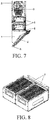
- each electrostatic filter 5 is provided and divided into an upper layer and a lower layer. Each layer is obtained by connecting two electrostatic filters 5 together, as shown in FIG. 8 .
- the electrostatic filters 5 of the upper and lower layers are arranged in a stack along the oil fume flow direction as shown in FIG. 7 .
- Each electrostatic filter 5 adopts a drawer-type mounting structure, and a front side wall thereof is provided with a handle for holding to pull out or push in the electrostatic filters 5, as shown in FIG. 8 .
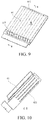
- the cyclone separator 4 of the cooker hood embodiment 2 is as shown in FIG. 9 and FIG. 10 .
- the number of the cyclone separators 4 of the cooker hood embodiment 2 is two, and two cyclone separators 4 are connected together, as shown in FIG. 6 .
- First outlets 412 and second outlets 413 are respectively formed on upper and lower ends of cyclone tubes 41 of the cyclone separator 4.
- An oil cup 6 of the cooker hood embodiment 2 is disposed at a bottom end of the smoke collecting chamber, and the top of the smoke collecting chamber is provided with a control panel 7, as shown in FIG. 6 .
Landscapes
- Engineering & Computer Science (AREA)
- Chemical & Material Sciences (AREA)
- Combustion & Propulsion (AREA)
- Mechanical Engineering (AREA)
- General Engineering & Computer Science (AREA)
- Ventilation (AREA)
Abstract
Description
- This application relates to the field of cooker hoods.
- Cooker hoods are common kitchen appliances in our daily lives. Kitchen oil fume problems are solved by people by mounting the cooker hoods. At present, cooker hoods provided with electrostatic filters have been proposed, but the performance thereof still needs to be further improved.
- Unless there is sufficient evidence, the prior art described herein does not mean that it is recognized that the prior art is well known to those of ordinary skill in the art to which this application relates before the filing date of this application.
- One objective of embodiments of this application is to provide an improved cooker hood provided with an electrostatic filter.
- One embodiment of this application relates to a cooker hood, including an electrostatic filter, and further including a rectifying plate, where along an oil fume flow direction, the rectifying plate is disposed upstream of the electrostatic filter. In this way, airflow flowing into the electrostatic filter is uniform, facilitating improving an oil fume filtering effect.
- In one possible design, the rectifying plate is provided with a plurality of air vents; and the air vents face an airflow inlet of the electrostatic filter. In this way, airflow flowing into the electrostatic filter is uniform, facilitating improving an oil fume filtering effect.
- In one possible design, the plurality of air vents are distributed in a mesh shape. In this way, airflow flowing into the electrostatic filter is uniform, facilitating improving an oil fume filtering effect.
- In one possible design, a plurality of electrostatic filters are provided, and the plurality of electrostatic filters are arranged in a stack along the oil fume flow direction.
- In one possible design, a fan is included; and along the oil fume flow direction, the fan is disposed downstream of the electrostatic filter.
- In one possible design, a smoke collecting hood and a case that is located above the smoke collecting hood are included; and along the oil fume flow direction, the rectifying plate, the electrostatic filter, and the fan are disposed in the case sequentially from bottom to top.
- In one possible design, a cyclone separator is further included; and along the oil fume flow direction, the cyclone separator is disposed upstream of the rectifying plate. Highspeed airflow flowing from the cyclone separator is processed by the rectifying plate, such that the airflow flowing into the electrostatic filter is uniform, facilitating improving an oil fume filtering effect.
- In one possible design, the cooker hood is an inclined cooker hood, including an inclined smoke collecting chamber; the cyclone separator is disposed in the smoke collecting chamber; the cyclone separator includes a plurality of cyclone tubes disposed in parallel; and side walls of the cyclone tubes are provided with air inlets, and the air inlets extend along an inclined direction of the smoke collecting chamber.
- In one possible design, first outlets and second outlets are respectively formed on upper and lower ends of the cyclone tubes.
- In one possible design, upper ends of the cyclone tubes are closed, and second outlets are formed on lower ends of the cyclone tubes. In one possible design, a driving device is further included, which is adapted to adjust a distance between the rectifying plate and the electrostatic filter.
- It should be explained herein that orientation expressions such as "from bottom to top", "bottom", "top", "above", "upper end", and "lower end" appearing in this application, unless otherwise specified, are based on common use states of the cooker hood.
- It should be explained herein that "first" and "second" appearing in the specification are used only for the purpose of description, and are not used for indicating relative importance; moreover, they are not used for defining the number of the features defined thereby; in addition, they are not used for defining logic relation or order relation of the features defined thereby.
- The contents of the technical solutions above of this application are not used for describing all possible implementations of this application. Throughout the application, guidance is provided in multiple places by enumerating examples, and these examples may be used in various feasible combinations.
- The following figures only give schematic illustrations and explanations of this application but are not intended to limit a scope of this application.
-
FIG. 1 is a schematic diagram of a cooker hood embodiment of this application; -
FIG. 2 is a schematic structural diagram of a cyclone separator of the cooker hood embodiment shown inFIG. 1 ; -
FIG. 3 is another schematic structural diagram of the cyclone separator of the cooker hood embodiment shown inFIG. 1 ; -
FIG. 4 is a schematic structural diagram of a rectifying plate of the cooker hood embodiment shown inFIG. 1 ; -
FIG. 5 is a schematic structural diagram of a rectifying plate of another cooker hood embodiment of this application; -
FIG. 6 is a schematic structural diagram of still another cooker hood embodiment of this application; -
FIG. 7 is a sectional view of the cooker hood embodiment shown inFIG. 6 ; -
FIG. 8 is a schematic structural diagram of an electrostatic filter of the cooker hood embodiment shown inFIG. 6 ; -
FIG. 9 is a schematic structural diagram of a cyclone separator of the cooker hood embodiment shown inFIG. 6 ; and -
FIG. 10 is a sectional view along direction B-B inFIG. 9 . -
- 1. Smoke collecting hood;
- 2. Case;
- 3. Fan;
- 4. Cyclone separator;
- 41. Cyclone tube;
- 411. Air inlet;
- 412. First outlet;
- 413. Second outlet;
- 5. Electrostatic filter;
- 6. Oil cup;
- 7. Control panel;
- 8. Rectifying plate;
- 81. Air vent.
- To make the objectives, solutions, and advantageous effects of this application clearer and more comprehensible, this application is further described below with reference to the accompanying drawings and preferred embodiments.
- This application provides a cooker hood embodiment. As shown in
FIG. 1 to FIG. 4 , the cooker hood is an inclined cooker hood, including asmoke collecting hood 1, a fan, acyclone separator 4, anelectrostatic filter 5, a rectifyingplate 8, an oil cup, and acase 2 located above thesmoke collecting hood 1. Along an oil fume flow direction, the rectifyingplate 8 is disposed upstream of theelectrostatic filter 5, the fan is disposed downstream of theelectrostatic filter 5, and thecyclone separator 4 is disposed upstream of the rectifyingplate 8. During running of the fan, the oil fume flow direction is shown by a one-way arrow inFIG. 1 ; and along the oil fume flow direction, the rectifyingplate 8, theelectrostatic filter 5, and the fan are disposed in thecase 2 sequentially from bottom to top. The rectifyingplate 8 is configured to be adapted to convey uniform airflow to theelectrostatic filter 5. - The
smoke collecting hood 1 includes an inclined smoke collecting chamber, and an inclination direction of the smoke collecting chamber is shown by a double sided arrow s inFIG. 1 . Thecyclone separator 4 is disposed in the smoke collecting chamber, as shown inFIG. 1 . Thecyclone separator 4 includes fivecyclone tubes 41 disposed in parallel, as shown inFIG. 2 andFIG. 3 . Inner cavities of thecyclone tubes 41 are cylindrical, as shown inFIG. 3 . Side walls of thecyclone tubes 41 are provided withair inlets 411, theair inlets 411 are parallel to each other, and theair inlets 411 all extend along the inclination direction of the smoke collecting chamber, as shown inFIG. 1 and FIG. 2 . Upper ends of thecyclone tubes 41 are closed, and second outlets are formed on lower ends of thecyclone tubes 41. The second outlets are only openings of thecyclone tubes 41 for the airflow to flow out. - The
electrostatic filter 5 is in a cuboid shape, as shown inFIG. 1 , an airflow inlet of theelectrostatic filter 5 is located at the bottom thereof, and an airflow outlet of theelectrostatic filter 5 is located at the top thereof. During running of the fan, the airflow flows through theelectrostatic filter 5 from bottom to top, as shown by the arrow inFIG. 1 . - The rectifying
plate 8 is provided with a plurality ofair vents 81; eachair vent 81 faces the airflow inlet of theelectrostatic filter 5, as shown inFIG. 1 , and the airflow flowing out of eachair vent 81 directly flows to the airflow inlet of theelectrostatic filter 5. The plurality ofair vents 81 are distributed in a mesh shape, as shown inFIG. 4 . The rectifyingplate 8 is a metal plate, and eachair vent 81 is made by stamping the metal plate. - During running of the fan, the airflow flows through the
cyclone separator 4, the air vents 81 of the rectifyingplate 8, theelectrostatic filter 5, and the fan sequentially, as shown by the arrow inFIG. 1 . When the airflow flows into thecyclone separator 4, the airflow spirals in cylindrical inner cavities of thecyclone tubes 41; grease is separated under the action of centrifugal force, flows out from the second outlet, and finally flows into the oil cup. - The airflow discharged by the
cyclone separator 4 is relatively concentrated and has a relatively high flow rate, while theelectrostatic filter 5 requires the airflow flowing therein to have a low flow rate and to be uniform to achieve a relatively good oil fume filtering effect; and disposing the rectifyingplate 8 between thecyclone separator 4 and theelectrostatic filter 5 can improve a matching effect between thecyclone separator 4 and theelectrostatic filter 5 to some extent. - The above is only one embodiment of this application, and other embodiments may be obtained by adding, deleting, modifying, or replacing some technical features. For example, the inner cavity of the cyclone tube may not be limited to be cylindrical, and may also a tubular structure with a cross section in the shape of a square, a polygon, etc. For another example, the specific structure of the rectifying plate is not limited to that shown in this embodiment; and other possible structures may also be adopted, for example, the structure provided with a flow guide flange as shown in
FIG. 5 . For another example, the number of the cyclone tubes of the cyclone separator may not be limited to five. For another example, the cooker hood may be an external exhaust type cooker hood, and may also be an internal circulation type cooker hood. For another example, the rectifying plate may also be disposed on the smoke collecting hood. For another example, a driving device may also be further disposed to adjust a distance between the rectifying plate and the electrostatic filter. Preferably, the driving device is configured to be adapted to drive the rectifying plate to move up and down. In this way, the position of the rectifying plate between the cyclone separator and the electrostatic filter can be adjusted according to actual needs, facilitating improving the matching effect between the cyclone separator and the electrostatic filter. - This application further provides another
cooker hood embodiment 2. As shown inFIG. 6 to FIG. 10 , thecooker hood embodiment 2 is obtained by further improvement on the basis of thecooker hood embodiment 1 above. Thecooker hood embodiment 2 mainly differs from thecooker hood embodiment 1 as follows. - In the
cooker hood embodiment 2, fourelectrostatic filters 5 are provided and divided into an upper layer and a lower layer. Each layer is obtained by connecting twoelectrostatic filters 5 together, as shown inFIG. 8 . Theelectrostatic filters 5 of the upper and lower layers are arranged in a stack along the oil fume flow direction as shown inFIG. 7 . Eachelectrostatic filter 5 adopts a drawer-type mounting structure, and a front side wall thereof is provided with a handle for holding to pull out or push in theelectrostatic filters 5, as shown inFIG. 8 . - The
cyclone separator 4 of thecooker hood embodiment 2 is as shown inFIG. 9 and FIG. 10 . The number of thecyclone separators 4 of thecooker hood embodiment 2 is two, and twocyclone separators 4 are connected together, as shown inFIG. 6 .First outlets 412 andsecond outlets 413 are respectively formed on upper and lower ends ofcyclone tubes 41 of thecyclone separator 4. - An
oil cup 6 of thecooker hood embodiment 2 is disposed at a bottom end of the smoke collecting chamber, and the top of the smoke collecting chamber is provided with a control panel 7, as shown inFIG. 6 . - For other structures and cooperation relations of the
cooker hood embodiment 2, please refer to corresponding descriptions of thecooker hood embodiment 1. Different embodiment components may be combined with each other in any feasible manner, to achieve the objectives of this application. - It should be additionally explained that this application should not be understood as being only limited to the implementations described above, but should be understood as covering all possible implementation situations determined by the claims of this application in conjunction with the disclosure of the specification. Therefore, any simple changes, equivalent variations, and modifications made to the above embodiments according to the technical essence of this application without departing from the contents of this application shall fall within the scope of this application.
Claims (11)
- A cooker hood, comprising an electrostatic filter (5), characterized by further comprising:a rectifying plate (8);wherein along an oil fume flow direction, the rectifying plate (8) is disposed upstream of the electrostatic filter (5).
- The cooker hood according to claim 1, characterized in that:the rectifying plate (8) is provided with a plurality of air vents (81); andthe air vents (81) face an airflow inlet of the electrostatic filter (5).
- The cooker hood according to claim 1, characterized in that:
the plurality of air vents (81) are distributed in a mesh shape. - The cooker hood according to claim 1, characterized in that:
a plurality of electrostatic filters (5) are provided, and the plurality of electrostatic filters (5) are arranged in a stack along the oil fume flow direction. - The cooker hood according to claim 1, characterized by comprising:a fan (3);wherein along the oil fume flow direction, the fan (3) is disposed downstream of the electrostatic filter (5).
- The cooker hood according to claim 5, characterized by comprising:a smoke collecting hood (1) and a case (2) that is located above the smoke collecting hood (1);wherein along the oil fume flow direction, the rectifying plate (8), the electrostatic filter (5), and the fan (3) are disposed in the case (2) sequentially from bottom to top.
- The cooker hood according to claim 1, characterized by further comprising:a cyclone separator (4);wherein along the oil fume flow direction, the cyclone separator (4) is disposed upstream of the rectifying plate (8).
- The cooker hood according to claim 7, characterized in that:the cooker hood is an inclined cooker hood, comprising an inclined smoke collecting chamber;the cyclone separator (4) is disposed in the smoke collecting chamber;the cyclone separator (4) comprises a plurality of cyclone tubes (41) disposed in parallel; andside walls of the cyclone tubes (41) are provided with air inlets (411), and the air inlets (411) extend along an inclined direction of the smoke collecting chamber.
- The cooker hood according to claim 8, characterized in that:
first outlets (412) and second outlets (413) are respectively formed on upper and lower ends of the cyclone tubes (41). - The cooker hood according to claim 8, characterized in that:
upper ends of the cyclone tubes (41) are closed, and second outlets (413) are formed on lower ends of the cyclone tubes (41). - The cooker hood according to any one of claims 1 to 10, characterized by further comprising:
a driving device, adapted to adjust a distance between the rectifying plate (8) and the electrostatic filter(5).
Applications Claiming Priority (1)
| Application Number | Priority Date | Filing Date | Title |
|---|---|---|---|
| CN202020284489.0U CN212841742U (en) | 2020-03-10 | 2020-03-10 | Smoke exhaust ventilator |
Publications (1)
| Publication Number | Publication Date |
|---|---|
| EP3879185A1 true EP3879185A1 (en) | 2021-09-15 |
Family
ID=74859768
Family Applications (1)
| Application Number | Title | Priority Date | Filing Date |
|---|---|---|---|
| EP21161211.4A Withdrawn EP3879185A1 (en) | 2020-03-10 | 2021-03-08 | Cooker hood |
Country Status (2)
| Country | Link |
|---|---|
| EP (1) | EP3879185A1 (en) |
| CN (1) | CN212841742U (en) |
Cited By (3)
| Publication number | Priority date | Publication date | Assignee | Title |
|---|---|---|---|---|
| CN114294666A (en) * | 2021-12-29 | 2022-04-08 | 深圳市智厨数字电器有限公司 | Smoke collecting structure free of connection sinking type installation |
| CN116538543A (en) * | 2022-01-26 | 2023-08-04 | 芜湖美的智能厨电制造有限公司 | Fume exhaust fan |
| CN117146311A (en) * | 2023-10-13 | 2023-12-01 | 山东省博兴县旺泉厨业有限公司 | An electrostatic oil fume purification machine that facilitates particle separation |
Citations (5)
| Publication number | Priority date | Publication date | Assignee | Title |
|---|---|---|---|---|
| US3890124A (en) * | 1974-07-22 | 1975-06-17 | Leslie D Howes | Combination grease centrifugal separator and flame trap |
| DE2412588A1 (en) * | 1974-03-15 | 1975-09-18 | Mulfingen Elektrobau Ebm | Extractor hood with filter for kitchens etc - also includes electrostatic filter to collect solid air-borne particles before recirculating air |
| US20050051158A1 (en) * | 2002-02-27 | 2005-03-10 | Bsh Bosch Und Siemens Hausgerate Gmbh | Extraction hood and method for the suction extraction and/or purification of contaminated carrier substances |
| TW201111713A (en) * | 2009-09-17 | 2011-04-01 | Chih-Hsing Chen | Household soot exhaust |
| CN108980936A (en) * | 2018-08-14 | 2018-12-11 | 佛山市卓健环保科技有限公司 | A kind of extreme low-altitude discharge static fume purification integrated machine of automatically cleaning |
-
2020
- 2020-03-10 CN CN202020284489.0U patent/CN212841742U/en active Active
-
2021
- 2021-03-08 EP EP21161211.4A patent/EP3879185A1/en not_active Withdrawn
Patent Citations (5)
| Publication number | Priority date | Publication date | Assignee | Title |
|---|---|---|---|---|
| DE2412588A1 (en) * | 1974-03-15 | 1975-09-18 | Mulfingen Elektrobau Ebm | Extractor hood with filter for kitchens etc - also includes electrostatic filter to collect solid air-borne particles before recirculating air |
| US3890124A (en) * | 1974-07-22 | 1975-06-17 | Leslie D Howes | Combination grease centrifugal separator and flame trap |
| US20050051158A1 (en) * | 2002-02-27 | 2005-03-10 | Bsh Bosch Und Siemens Hausgerate Gmbh | Extraction hood and method for the suction extraction and/or purification of contaminated carrier substances |
| TW201111713A (en) * | 2009-09-17 | 2011-04-01 | Chih-Hsing Chen | Household soot exhaust |
| CN108980936A (en) * | 2018-08-14 | 2018-12-11 | 佛山市卓健环保科技有限公司 | A kind of extreme low-altitude discharge static fume purification integrated machine of automatically cleaning |
Cited By (3)
| Publication number | Priority date | Publication date | Assignee | Title |
|---|---|---|---|---|
| CN114294666A (en) * | 2021-12-29 | 2022-04-08 | 深圳市智厨数字电器有限公司 | Smoke collecting structure free of connection sinking type installation |
| CN116538543A (en) * | 2022-01-26 | 2023-08-04 | 芜湖美的智能厨电制造有限公司 | Fume exhaust fan |
| CN117146311A (en) * | 2023-10-13 | 2023-12-01 | 山东省博兴县旺泉厨业有限公司 | An electrostatic oil fume purification machine that facilitates particle separation |
Also Published As
| Publication number | Publication date |
|---|---|
| CN212841742U (en) | 2021-03-30 |
Similar Documents
| Publication | Publication Date | Title |
|---|---|---|
| JP6066136B2 (en) | Vacuum cleaner separation device | |
| US20150096446A1 (en) | Dust-collecting device of a secondary dust-collecting machine | |
| EP3767184B1 (en) | Cooktop with downdraft extraction | |
| CN212841742U (en) | Smoke exhaust ventilator | |
| CN100571883C (en) | Cyclone collector | |
| CN111351087B (en) | Integrated stove | |
| CN107898383B (en) | Dust cup and vacuum cleaner having the same | |
| JP2014100276A (en) | Dust collector and vacuum cleaner | |
| CN220715151U (en) | Cyclone separator and smoking equipment for oil fume separation | |
| EP2799124A1 (en) | Particle separator | |
| EP3795256A1 (en) | Cyclonic dust filter device | |
| CN219199300U (en) | Fume exhaust fan | |
| CN214861874U (en) | Air filtering device | |
| KR100624823B1 (en) | Baffle Filter | |
| JP2010075793A (en) | Dust collecting device and vacuum cleaner having the same | |
| CN211633085U (en) | Cyclone separation device and dust collector | |
| CN114484689B (en) | Sand removing device | |
| CN224188654U (en) | Fume exhauster | |
| CN223555743U (en) | Double-flow-path oil-gas separation device | |
| CN222597821U (en) | Range hood and kitchen system comprising same | |
| CN107752905B (en) | Dust cup and vacuum cleaner having the same | |
| CN117138460B (en) | Cyclone separator for oil smoke separation and smoking device | |
| CN212003302U (en) | A new type of oil and gas separator | |
| CN223636423U (en) | Oil separator | |
| CN215808734U (en) | grease pump |
Legal Events
| Date | Code | Title | Description |
|---|---|---|---|
| PUAI | Public reference made under article 153(3) epc to a published international application that has entered the european phase |
Free format text: ORIGINAL CODE: 0009012 |
|
| STAA | Information on the status of an ep patent application or granted ep patent |
Free format text: STATUS: THE APPLICATION HAS BEEN PUBLISHED |
|
| AK | Designated contracting states |
Kind code of ref document: A1 Designated state(s): AL AT BE BG CH CY CZ DE DK EE ES FI FR GB GR HR HU IE IS IT LI LT LU LV MC MK MT NL NO PL PT RO RS SE SI SK SM TR |
|
| STAA | Information on the status of an ep patent application or granted ep patent |
Free format text: STATUS: REQUEST FOR EXAMINATION WAS MADE |
|
| 17P | Request for examination filed |
Effective date: 20220315 |
|
| RBV | Designated contracting states (corrected) |
Designated state(s): AL AT BE BG CH CY CZ DE DK EE ES FI FR GB GR HR HU IE IS IT LI LT LU LV MC MK MT NL NO PL PT RO RS SE SI SK SM TR |
|
| STAA | Information on the status of an ep patent application or granted ep patent |
Free format text: STATUS: EXAMINATION IS IN PROGRESS |
|
| 17Q | First examination report despatched |
Effective date: 20230614 |
|
| GRAP | Despatch of communication of intention to grant a patent |
Free format text: ORIGINAL CODE: EPIDOSNIGR1 |
|
| STAA | Information on the status of an ep patent application or granted ep patent |
Free format text: STATUS: GRANT OF PATENT IS INTENDED |
|
| RIC1 | Information provided on ipc code assigned before grant |
Ipc: B03C 3/36 20060101ALI20230829BHEP Ipc: B03C 3/15 20060101ALI20230829BHEP Ipc: B03C 3/02 20060101ALI20230829BHEP Ipc: B03C 3/011 20060101ALI20230829BHEP Ipc: F24C 15/20 20060101AFI20230829BHEP |
|
| INTG | Intention to grant announced |
Effective date: 20230913 |
|
| STAA | Information on the status of an ep patent application or granted ep patent |
Free format text: STATUS: THE APPLICATION IS DEEMED TO BE WITHDRAWN |
|
| 18D | Application deemed to be withdrawn |
Effective date: 20240124 |