EP3879180A1 - Appliance comprising control panel assembly - Google Patents
Appliance comprising control panel assembly Download PDFInfo
- Publication number
- EP3879180A1 EP3879180A1 EP21159114.4A EP21159114A EP3879180A1 EP 3879180 A1 EP3879180 A1 EP 3879180A1 EP 21159114 A EP21159114 A EP 21159114A EP 3879180 A1 EP3879180 A1 EP 3879180A1
- Authority
- EP
- European Patent Office
- Prior art keywords
- mounting
- control panel
- panel assembly
- appliance
- housing
- Prior art date
- Legal status (The legal status is an assumption and is not a legal conclusion. Google has not performed a legal analysis and makes no representation as to the accuracy of the status listed.)
- Withdrawn
Links
Images


Classifications
-
- F—MECHANICAL ENGINEERING; LIGHTING; HEATING; WEAPONS; BLASTING
- F24—HEATING; RANGES; VENTILATING
- F24C—DOMESTIC STOVES OR RANGES ; DETAILS OF DOMESTIC STOVES OR RANGES, OF GENERAL APPLICATION
- F24C3/00—Stoves or ranges for gaseous fuels
- F24C3/12—Arrangement or mounting of control or safety devices
-
- H—ELECTRICITY
- H05—ELECTRIC TECHNIQUES NOT OTHERWISE PROVIDED FOR
- H05K—PRINTED CIRCUITS; CASINGS OR CONSTRUCTIONAL DETAILS OF ELECTRIC APPARATUS; MANUFACTURE OF ASSEMBLAGES OF ELECTRICAL COMPONENTS
- H05K7/00—Constructional details common to different types of electric apparatus
- H05K7/14—Mounting supporting structure in casing or on frame or rack
-
- D—TEXTILES; PAPER
- D06—TREATMENT OF TEXTILES OR THE LIKE; LAUNDERING; FLEXIBLE MATERIALS NOT OTHERWISE PROVIDED FOR
- D06F—LAUNDERING, DRYING, IRONING, PRESSING OR FOLDING TEXTILE ARTICLES
- D06F34/00—Details of control systems for washing machines, washer-dryers or laundry dryers
- D06F34/28—Arrangements for program selection, e.g. control panels therefor; Arrangements for indicating program parameters, e.g. the selected program or its progress
- D06F34/34—Arrangements for program selection, e.g. control panels therefor; Arrangements for indicating program parameters, e.g. the selected program or its progress characterised by mounting or attachment features, e.g. detachable control panels or detachable display panels
-
- F—MECHANICAL ENGINEERING; LIGHTING; HEATING; WEAPONS; BLASTING
- F16—ENGINEERING ELEMENTS AND UNITS; GENERAL MEASURES FOR PRODUCING AND MAINTAINING EFFECTIVE FUNCTIONING OF MACHINES OR INSTALLATIONS; THERMAL INSULATION IN GENERAL
- F16B—DEVICES FOR FASTENING OR SECURING CONSTRUCTIONAL ELEMENTS OR MACHINE PARTS TOGETHER, e.g. NAILS, BOLTS, CIRCLIPS, CLAMPS, CLIPS OR WEDGES; JOINTS OR JOINTING
- F16B5/00—Joining sheets or plates, e.g. panels, to one another or to strips or bars parallel to them
- F16B5/02—Joining sheets or plates, e.g. panels, to one another or to strips or bars parallel to them by means of fastening members using screw-thread
- F16B5/025—Joining sheets or plates, e.g. panels, to one another or to strips or bars parallel to them by means of fastening members using screw-thread specially designed to compensate for misalignement or to eliminate unwanted play
-
- F—MECHANICAL ENGINEERING; LIGHTING; HEATING; WEAPONS; BLASTING
- F24—HEATING; RANGES; VENTILATING
- F24C—DOMESTIC STOVES OR RANGES ; DETAILS OF DOMESTIC STOVES OR RANGES, OF GENERAL APPLICATION
- F24C7/00—Stoves or ranges heated by electric energy
- F24C7/08—Arrangement or mounting of control or safety devices
-
- H—ELECTRICITY
- H05—ELECTRIC TECHNIQUES NOT OTHERWISE PROVIDED FOR
- H05K—PRINTED CIRCUITS; CASINGS OR CONSTRUCTIONAL DETAILS OF ELECTRIC APPARATUS; MANUFACTURE OF ASSEMBLAGES OF ELECTRICAL COMPONENTS
- H05K5/00—Casings, cabinets or drawers for electric apparatus
- H05K5/0017—Casings, cabinets or drawers for electric apparatus with operator interface units
-
- H—ELECTRICITY
- H05—ELECTRIC TECHNIQUES NOT OTHERWISE PROVIDED FOR
- H05K—PRINTED CIRCUITS; CASINGS OR CONSTRUCTIONAL DETAILS OF ELECTRIC APPARATUS; MANUFACTURE OF ASSEMBLAGES OF ELECTRICAL COMPONENTS
- H05K5/00—Casings, cabinets or drawers for electric apparatus
- H05K5/02—Details
- H05K5/0217—Mechanical details of casings
-
- A—HUMAN NECESSITIES
- A47—FURNITURE; DOMESTIC ARTICLES OR APPLIANCES; COFFEE MILLS; SPICE MILLS; SUCTION CLEANERS IN GENERAL
- A47L—DOMESTIC WASHING OR CLEANING; SUCTION CLEANERS IN GENERAL
- A47L15/00—Washing or rinsing machines for crockery or tableware
- A47L15/42—Details
- A47L15/4293—Arrangements for programme selection, e.g. control panels; Indication of the selected programme, programme progress or other parameters of the programme, e.g. by using display panels
-
- D—TEXTILES; PAPER
- D06—TREATMENT OF TEXTILES OR THE LIKE; LAUNDERING; FLEXIBLE MATERIALS NOT OTHERWISE PROVIDED FOR
- D06F—LAUNDERING, DRYING, IRONING, PRESSING OR FOLDING TEXTILE ARTICLES
- D06F39/00—Details of washing machines not specific to a single type of machines covered by groups D06F9/00 - D06F27/00
- D06F39/12—Casings; Tubs
-
- F—MECHANICAL ENGINEERING; LIGHTING; HEATING; WEAPONS; BLASTING
- F16—ENGINEERING ELEMENTS AND UNITS; GENERAL MEASURES FOR PRODUCING AND MAINTAINING EFFECTIVE FUNCTIONING OF MACHINES OR INSTALLATIONS; THERMAL INSULATION IN GENERAL
- F16B—DEVICES FOR FASTENING OR SECURING CONSTRUCTIONAL ELEMENTS OR MACHINE PARTS TOGETHER, e.g. NAILS, BOLTS, CIRCLIPS, CLAMPS, CLIPS OR WEDGES; JOINTS OR JOINTING
- F16B19/00—Bolts without screw-thread; Pins, including deformable elements; Rivets
- F16B19/02—Bolts or sleeves for positioning of machine parts, e.g. notched taper pins, fitting pins, sleeves, eccentric positioning rings
-
- F—MECHANICAL ENGINEERING; LIGHTING; HEATING; WEAPONS; BLASTING
- F16—ENGINEERING ELEMENTS AND UNITS; GENERAL MEASURES FOR PRODUCING AND MAINTAINING EFFECTIVE FUNCTIONING OF MACHINES OR INSTALLATIONS; THERMAL INSULATION IN GENERAL
- F16B—DEVICES FOR FASTENING OR SECURING CONSTRUCTIONAL ELEMENTS OR MACHINE PARTS TOGETHER, e.g. NAILS, BOLTS, CIRCLIPS, CLAMPS, CLIPS OR WEDGES; JOINTS OR JOINTING
- F16B5/00—Joining sheets or plates, e.g. panels, to one another or to strips or bars parallel to them
- F16B5/06—Joining sheets or plates, e.g. panels, to one another or to strips or bars parallel to them by means of clamps or clips
- F16B5/0607—Joining sheets or plates, e.g. panels, to one another or to strips or bars parallel to them by means of clamps or clips joining sheets or plates to each other
- F16B5/0614—Joining sheets or plates, e.g. panels, to one another or to strips or bars parallel to them by means of clamps or clips joining sheets or plates to each other in angled relationship
Definitions
- the present disclosure generally relates to an alignment system for an appliance, and more specifically, to an alignment system that centers a console on an appliance.
- an appliance includes a control panel assembly having a rearwardly extending mounting member.
- the rearwardly extending mounting member includes a body portion having an outer edge with one or more slots disposed through the body portion and inwardly opening from the outer edge of the body portion.
- a housing includes a support bracket having a support surface with one or more mounting apertures disposed therethrough.
- One or more locating pins are received through the one or more mounting apertures.
- the locating pins include body portions upwardly extending from the support surface of the support bracket.
- the one or more locating pins are removably received in the one or more slots of the rearwardly extending mounting member of the control panel assembly.
- an appliance includes a housing with a frame assembly having a support bracket.
- the support bracket includes at least one locating pin.
- a mounting plate includes a front surface with a mounting member outwardly extending from the front surface of the mounting plate.
- the mounting member includes at least one slot through which the at least one locating pin is slidably received.
- a method of mounting a control panel assembly to an appliance comprises the steps of: (1) providing a control panel assembly having a mounting member with at least one slot (2) providing a housing with a support bracket having at least one locating pin upwardly extending therefrom (3) positioning the control panel assembly in a centered position on the support plate by positioning the at least one locating pin of the housing in the at least one slot of the control panel assembly (4) retaining the control panel assembly in the centered position on the support plate by operably coupling reciprocal mounting features disposed on the housing and the control panel assembly to one another after the control panel assembly is positioned in the centered position.
- the present illustrated embodiments reside primarily in combinations of method steps and apparatus components related to an alignment system for a console of an appliance. Accordingly, the apparatus components and method steps have been represented, where appropriate, by conventional symbols in the drawings, showing only those specific details that are pertinent to understanding the embodiments of the present disclosure so as not to obscure the disclosure with details that will be readily apparent to those of ordinary skill in the art having the benefit of the description herein. Further, like numerals in the description and drawings represent like elements.
- the terms “upper,” “lower,” “right,” “left,” “rear,” “front,” “vertical,” “horizontal,” and derivatives thereof shall relate to the disclosure as oriented in FIG. 1 .
- the term “front” shall refer to the surface of the element closer to an intended viewer, and the term “rear” shall refer to the surface of the element further from the intended viewer.
- the disclosure may assume various alternative orientations, except where expressly specified to the contrary.
- the specific devices and processes illustrated in the attached drawings, and described in the following specification are simply exemplary embodiments of the inventive concepts defined in the appended claims. Hence, specific dimensions and other physical characteristics relating to the embodiments disclosed herein are not to be considered as limiting, unless the claims expressly state otherwise.
- reference numeral 10 generally designates an appliance, shown in the form of a built-in oven, but may also include a range having an oven portion, a microwave oven, a toaster oven, a refrigerator or a laundry care appliance, such as a front loading washer or dryer.
- the appliance 10 includes a housing 12 having upper and lower sides 14, 16 which are interconnected by first and second sidewalls 18, 20.
- the housing 12 further includes a rear panel 22 and an open front portion 24.
- the open front portion 24 opens into a cooking cavity 26 generally defined by the upper and lower sides 14, 16 and the first and second sidewalls 18, 20 of the housing 12.
- the housing 12 further includes a frame assembly 28 disposed around the open front portion 24 of the housing 12.
- the frame assembly 28 includes a support bracket 30, best shown in FIG. 3 that is positioned above the cooking cavity 26.
- the support bracket 30 is interconnected at opposite sides thereof by first and second side members 32, 34 of the frame assembly 28.
- the frame assembly 28 is shown in FIG. 1 as a front frame assembly, and may also include a lower bracket 36 interconnecting the first and second side members 32, 34.
- the appliance 10 includes a control panel assembly 40 that is mounted to the housing 12.
- the control panel assembly 40 is supported on the support bracket 30 of the frame assembly 28 in a centered position, as further described below.
- the control panel assembly 40 is mounted above the cooking cavity 26 in a centered position on the housing 12, as shown in FIG. 1 .
- the control panel assembly 40 is mounted on a front portion of the housing 12, such that the control panel assembly 40 is easily accessible to a user of the appliance 10.
- the control panel assembly 40 defines a user interface console for the appliance 10, such that a user may control the features of the appliance 10 through the control panel assembly 40, as further described below.
- the control panel assembly 40 may be referred to herein as a console or console assembly.
- the control panel assembly 40 includes a mounting plate 42 with a trim member 100 mounted on the mounting plate 42.
- a pane 90 is further mounted to the mounting plate 42 and includes a user interface 80 mounted thereto. Both the control panel assembly 40 and the user interface 80 are centered on the housing 12 and centered over the cooking cavity 26 of the appliance 10.
- the mounting plate 42 of the control panel assembly 40 includes a front surface 44.
- the mounting plate 42 further includes an upper member 46 spaced-apart from a mounting member 48 and interconnected by first and second side portions 50, 52. Together, the upper member 46, the mounting member 48 and the first and second side portions 50, 52 cooperate to surround and define a window 54 that is generally centrally disposed on the mounting plate 42.
- the mounting member 48 outwardly extends from the front surface 44 of the mounting plate 42 in a rearward direction.
- the mounting member 48 includes a body portion 56 having an outer edge 58.
- First and second slots 60, 62 are disposed through the body portion 56 and open inwardly from the outer edge 58 of the body portion 56.
- the first and second slots 60, 62 are contemplated to be similar or identical in configuration, such that like reference numerals are used to describe common features of both the first and second slots 60, 62.
- the first and second slots 60, 62 open inwardly from the outer edge 58 into the body portion 56 at open front portion 64 ( FIGS. 3 and 5 ) of the first and second slots 60, 62, and are directed towards the front surface 44 of the mounting plate 42 from the outer edge 58 of the body portion 56 towards the closed end portions 66 ( FIGS. 3 and 5 ) of the first and second slots 60, 62.
- the mounting member 48 is a rearwardly extending mounting member having the first and second slots 60, 62 that are used to help align the control panel assembly 40 on the housing 12 of the appliance 10, as further described below.
- the mounting member 48 includes the first and second slots 60, 62, but may include more slots disposed through the body portion 56 thereof. It is also contemplated that a single slot may be disposed on the mounting member 48, without departing from the spirit of the present concept.
- the mounting plate 42 includes first and second mounting brackets 70, 72 which each include upper and lower mounting apertures 74A, 74B disposed through associated body portions 76 thereof.
- the first and second mounting brackets 70, 72 are disposed on opposed sides of the mounting plate 42, such that the first and second mounting brackets 70, 72 are spaced-apart from one another and outwardly extend from the front surface 44 of the mounting plate 42 in a rearward direction.
- the first and second mounting brackets 70, 72 are disposed on opposed first and second sides 40A, 40B of the control panel assembly 40, and rearwardly extend from the control panel assembly 40, as shown in the assembled condition in FIG. 3 .
- FIG. 1 first and second mounting brackets 70, 72 which each include upper and lower mounting apertures 74A, 74B disposed through associated body portions 76 thereof.
- the first and second mounting brackets 70, 72 are disposed on opposed sides of the mounting plate 42, such that the first and second mounting brackets 70, 72 are spaced-apart from one another and outwardly extend
- the first and second mounting brackets 70, 72 are disposed above the mounting member 48 on the mounting plate 42. It is contemplated that the first and second mounting brackets 70, 72 as well as the mounting plate 42 may include portions of a sheet metal substrate that remain after the window 54 is stamped into the mounting plate 42. After stamping the window 54, the portions of the sheet metal material can be bent rearwardly to define the first and second mounting bracket 70, 72 as well as the mounting member 48.
- the user interface 80 of the control panel assembly 40 includes first and second sides 82, 84.
- the user interface 80 may include activation buttons, a display screen, a controller, and any other component parts necessary for a user to control the features of the appliance via the user interface 80.
- the user interface 80 is contemplated to be electronically coupled to a controller for controlling aspects of the appliance 10.
- the user interface 80 will include programming interface options for controlling aspects of the cooking cavity 26 and any heating element or heating features configured to heat the cooking cavity 26.
- the user interface 80 may include a digital interface that uses a touchscreen graphical user interface, or may include physical buttons and switches for controlling the appliance 10.
- the pane 90 of the control panel assembly 40 includes first and second surfaces 92, 94.
- the pane 90 may be a glass pane or acrylic pane, through which the user interface 80 can be controlled.
- the pane 90 may include a conductive touchscreen material that allows a user to operate the user interface 80.
- the user interface 80 is mounted to the second surface 94 of the pane 90 at the first side 82 of the user interface 80.
- the pane 90 is contemplated to be mounted to the mounting plate 42 at the front surface 44 of the mounting plate 42 at the second surface 94 of the pane 90.
- the user interface 80 is contemplated to be centered on the second surface 94 of the pane 90, such that the user interface 80 can be centered on the control panel assembly 40 in assembly, as best shown in FIGS. 3 and 4 .
- Other positions for the user interface 80 are also contemplated on the control panel assembly 40.
- the user interface 80 is mounted to the mounting plate 42 through the pane 90.
- the control panel assembly 40 includes a trim member 100 having upper and lower members 102, 104 that are interconnected by first and second side members 106, 108.
- the upper and lower members 102, 104 and the first and second side members 106, 108 cooperate to define a window 110 that is generally centrally disposed on the trim member 100.
- the trim member 100 is contemplated to be mounted to the first surface 92 of the pane 90, and is further contemplated to be mounted to the mounting plate 42.
- the trim member 100 may further be mounted to the housing 12 of the appliance 10 using mounting features 112, 114 and 116 extending outwardly from the lower member 104.
- the pane 90 is shown positioned within the window 110 defined by the trim member 100.
- the control panel assembly 40 is shown in an assembled condition and exploded away from the housing 12 of the appliance 10.
- the support bracket 30 of the frame assembly 28 of the housing 12 includes a support surface 118 which defines an upper surface of the support bracket 30.
- the support bracket 30 further includes first and second mounting apertures 120, 122 disposed therethrough.
- the first and second locating pins 130, 132 are received through the first and second mounting apertures 120, 122 of the support bracket 30, such that the first and second locating pins 130, 132 upwardly extend from the support surface 118 of the support bracket 30.
- the first and second locating pins 130, 132 are contemplated to be similar or identical in configuration, such that like reference numerals are used to describe common features of both the first and second locating pins 130, 132.
- the locating pins 130, 132 each include body portions 134 that upwardly extend from the support surface 118 of the support bracket 30.
- the first and second locating pins 130, 132 are configured to be horizontally received within the first and second slots 60, 62, respectively, when the control panel assembly 40 is mounted on the housing 12 at the support bracket 30.
- dashed lines are used to indicate the horizontal reception of the locating pins 130, 132 to the first and second slots 60, 62.
- the first and second slots 60, 62 are configured to horizontally receive the first and second locating pins 130, 132, respectively, in the mounting of the control panel assembly 40 to the housing 12 of the appliance 10.
- the first and second slots 60, 62 are contemplated to be spaced-apart a distance that correlates to a spacing provided between the first and second locating pins 130, 132, for the associated engagement of the same when mounting the control panel assembly 40 to the support bracket 30.
- the housing 12 of the appliance 10 further includes first and second mounting features 170, 172.
- the first and second mounting features 170, 172 are contemplated to be similar or identical in configuration, such that like reference numerals are used to describe common features shared between the first and second mounting features 170, 172.
- the first and second mounting features 170, 172 include body portions 176 which upwardly extend from opposed first and second sides 30A, 30B of the support bracket 30.
- the body portions 176 may be mounted to the frame assembly 28 at the first and second side members 32, 34, respectively, of the frame assembly 28.
- the first and second mounting features 170, 172 each include an upper mounting aperture 174A disposed above a lower mounting slot 174B.
- the upper mounting apertures 174A of the first and second mounting features 170, 172 of the housing 12 are configured to align with the upper mounting apertures 74A of the first and second mounting brackets 70, 72, respectively.
- the lower mounting slots 174B of the first and second mounting features 170, 172 of the housing 12 are configured to align with the lower mounting apertures 74B of the first and second mounting brackets 70, 72, respectively.
- the control panel assembly 40 can be fixedly coupled to the housing 12 after being centered on the support bracket 30 by the engagement of the first and second locating pins 130, 132 with the first and second slots 60, 62, respectively, of the control panel assembly 40.
- first and second mounting brackets 70, 72 and the first and second mounting features 170, 172 is provided using fasteners received through the respective mounting apertures 74A, 74B, 174A and mounting slots 174B thereof.
- the lower mounting slots 174B of the first and second mounting features 170, 172 are oblong-shaped apertures which can accommodate variations in control panel and appliance components to provide for specific and consistent spacing between edges of the control panel assembly 40 and adjacent edges of the housing 12, or components thereof (such as an appliance door).
- the control panel assembly 40 is shown mounted to the housing 12 at the support bracket 30 thereof. Specifically, the first and second locating pins 130, 132 are shown received within the first and second slots 60, 62.
- the first and second locating pins 130, 132 are specifically positioned on the support bracket 30, and the first and second slots 60, 62 are specifically positioned on the mounting member 48 of the mounting plate 42, such that when the first and second locating pins 130, 132 are horizontally received within the first and second slots 60, 62, the control panel assembly 40 is centered on the housing 12 of the appliance 10.
- FIG. 1 the first and second locating pins 130, 132 are shown received within the first and second slots 60, 62.
- the user interface 80 is contemplated to be centered on the pane 90, such that the user interface 80 is also centered on the housing 12 of the appliance 10.
- the engagement between the first and second locating pins 130, 132 and the first and second slots 60, 62 provides for a laterally fixed position for the control panel assembly 40 relative to the housing 12. In this way, the engagement between the first and second locating pins 130, 132 and the first and second slots 60, 62 resist lateral movement in the direction as indicated by arrow 150.
- the control panel assembly 40 can be secured in the desired centered position by fixedly coupling the first and second mounting brackets 70, 72 of the mounting plate 42 to the first and second mounting features 170, 172 of the housing 12.
- the upper and lower mounting apertures 74A, 74B of the first and second mounting brackets 70, 72 are configured to receive fasteners which fixedly couple to the upper mounting apertures 174A and the lower mounting slots 174B of the first and second mounting features 170, 172. In this way, the control panel assembly 40 is retained in the centered position on the housing 12.
- first and second locating pins 130, 132 are shown received within the first and second slots 60, 62, respectively, and are contemplated to be removably received within the first and second slots 60, 62. While two locating pins (first and second locating pins 130, 132) are shown in the embodiment of FIG. 4 along with two slots (first and second slots 60, 62), is contemplated that more slot and pin combinations may be included in the alignment system of the present concept for aligning the control panel assembly 40 on the housing 12. Further, it is contemplated that a single locating pin and slot combination may be provided as a locating feature for the control panel assembly 40.
- the locating pin 130 is shown upwardly extending from the support surface 118 of the support bracket 30 through the mounting aperture 120.
- the locating pin 130 includes a body portion 134 that upwardly extends from the support surface 118 of the support bracket 30.
- the locating pin 130 shown in FIG. 5 may include expanding clinch pin assemblies that can expand to fixedly engage the mounting aperture 120 to provide a fixed coupling between the support bracket 30 and the locating pin 130.
- the locating pin 130 is configured to be slidably, removably and horizontally received within the slot 60 in the direction as indicated by arrow 152.
- the body portion 134 of the locating pin 130 is received through the open front portion 64 of the slot 60 in the horizontal manner as indicated by arrow 152 as the locating pin 130 nears the closed end portion 66 of the slot 60. It is not necessary that the locating pin 130 be fully seated in the slot 60 in order to combat lateral movement in the direction as indicated by arrow 150.
- the slot 60 includes first and second inner edge portions 140, 142 that are spaced-apart a distance 144 which is contemplated to closely received the body portion 134 of the locating pin 130 to resist lateral movement of the control panel assembly 40 once the locating pin 130 is received within the slot 60.
- control panel assembly 40 can be moved forward and rearward with the locating pin 130 slidably received in the slot 60 to provide alignment between the control panel assembly 40 and other features of the appliance 10.
- reception of the locating pin 130 within the slot 60 of the mounting member 48 of the mounting plate 42 of the control panel assembly 40 correlates to a centered position of the control panel assembly 40 on the housing 12, and may also correlate to a centered position of the user interface 80 as mounted to the control panel assembly 40.
- the present concept further includes a method 200 of mounting a control panel assembly to an appliance.
- the method 200 may comprise the step 202 of providing a control panel assembly having a mounting member with at least one inwardly opening slot.
- the control panel assembly may include a control panel assembly similar to control panel assembly 40 described above having a mounting member 48 with at least one inwardly opening slot, such as inwardly opening slots 60, 62 described above.
- the method 200 may further include the step 204 of providing a housing with a support bracket having at least one locating pin upwardly extending therefrom.
- the housing provided in the method 200 may include a housing similar to housing 12 described above having the support bracket 30 with at least one locating pin 130 extending upwardly therefrom.
- the method 200 may further include the step 206 of positioning the control panel assembly in a centered position on the support plate by positioning the at least one locating pin of the housing in the at least one rearwardly opening slot of the control panel assembly, as discussed above with reference to FIGS. 3 and 4 .
- the method 200 may further include the step 208 of retaining the control panel assembly in the centered position on the support plate by operably coupling reciprocal mounting features disposed on the housing and the control panel assembly to one another after the control panel assembly is positioned in the centered position.
- the reciprocal mounting features provided in the method 200 are contemplated to be mounting features such as the first and second mounting brackets 70, 72 which are operably coupled to the first and second mounting features 170,172.
- an appliance includes a control panel assembly having a rearwardly extending mounting member.
- the rearwardly extending mounting member includes a body portion having an outer edge with one or more slots disposed through the body portion and inwardly opening from the outer edge of the body portion.
- a housing includes a support bracket having a support surface with one or more mounting apertures disposed therethrough.
- One or more locating pins are received through the one or more mounting apertures.
- the locating pins include body portions upwardly extending from the support surface of the support bracket.
- the one or more locating pins are removably received in the one or more slots of the rearwardly extending mounting member of the control panel assembly.
- the one or more locating pins and the one or more slots are positioned such that the control panel assembly is supported in a centered position on the housing when the one or more locating pins are removably received in the one or more slots.
- one or more mounting brackets are disposed on the control panel assembly and one or more mounting features are disposed on the housing.
- the one or more mounting brackets of the control panel assembly are operably coupled to the one or more mounting features of the housing to retain the control panel assembly in the centered position.
- the one or more mounting brackets include first and second mounting brackets spaced-apart from one another and rearwardly extending from the control panel assembly.
- the one or more locating pins are horizontally received in the one or more slots.
- the one or more locating pins include first and second locating pins.
- the one or more slots include first and second slots in which the first and second locating pins are respectively received.
- an appliance includes a housing with a frame assembly having a support bracket.
- the support bracket includes at least one locating pin.
- a mounting plate includes a front surface with a mounting member outwardly extending from the front surface of the mounting plate.
- the mounting member includes at least one slot through which the at least one locating pin is slidably received.
- the appliance includes a user interface mounted on the mounting plate.
- the at least one locating pin and the at least one slot are respectively positioned on the support bracket and the mounting member, such that the user interface is supported in a centered position on the support bracket when the at least one locating pin is received in the at least one slot.
- first and second mounting brackets are disposed above the mounting member and outwardly extending from the front surface of the mounting plate.
- first and second mounting features are disposed on the housing on opposed sides of the support bracket, respectively.
- the first and second mounting brackets are operably coupled to the first and second mounting features, respectively, to retain the user interface in the centered position.
- the mounting member includes a body portion having an outer edge.
- the at least one slot of the mounting member inwardly opens into the body portion from the outer edge of the body portion.
- the at least one locating pin includes a body portion upwardly extending from an upper surface of the support bracket.
- the body portion of the at least one locating pin is configured to be horizontally received in the at least one slot.
- the housing includes a cooking cavity disposed below the support bracket.
- the mounting plate includes a user interface mounted thereto to define a control panel assembly.
- a method of mounting a control panel assembly to an appliance comprises the steps of: (1) providing a control panel assembly having a mounting member with at least one slot (2) providing a housing with a support bracket having at least one locating pin upwardly extending therefrom (3) positioning the control panel assembly in a centered position on the support plate by positioning the at least one locating pin of the housing in the at least one slot of the control panel assembly (4) retaining the control panel assembly in the centered position on the support plate by operably coupling reciprocal mounting features disposed on the housing and the control panel assembly to one another after the control panel assembly is positioned in the centered position.
- the step of positioning the at least one locating pin of the housing in the at least one slot further includes, horizontally and slidably receiving the locating pin in the at least one slot.
- the mounting member includes an outer edge and further wherein the at least one slot opens from the outer edge of the mounting member.
- the step of operably coupling reciprocal mounting features disposed on the housing and the control panel assembly to one another further includes, fastening first and second mounting brackets of the control panel assembly to first and second mounting features disposed on the housing on opposed sides of the support bracket.
- the step of positioning the at least one locating pin of the housing in the at least one slot further includes, positioning first and second locating pins of the housing in first and second slots of the mounting member respectively.
- an appliance includes a control panel assembly having a rearwardly extending mounting member.
- the rearwardly extending mounting member includes a body portion having an outer edge with one or more slots disposed through the body portion and inwardly opening from the outer edge of the body portion.
- a housing includes a support bracket having a support surface with one or more mounting apertures disposed therethrough.
- One or more locating pins are received through the one or more mounting apertures.
- the locating pins include body portions upwardly extending from the support surface of the support bracket.
- the one or more locating pins are removably received in the one or more slots of the rearwardly extending mounting member of the control panel assembly.
- the one or more locating pins and the one or more slots are positioned such that the control panel assembly is supported in a centered position on the housing when the one or more locating pins are removably received in the one or more slots.
- one or more mounting brackets are disposed on the control panel assembly and rearwardly extend therefrom.
- one or more mounting features are disposed on the housing.
- the one or more mounting brackets of the control panel assembly are operably coupled to the one or more mounting features of the housing to retain the control panel assembly in the centered position.
- the one or more mounting features include a first mounting feature and a second mounting feature disposed on opposed first and second sides, respectively, of the support bracket.
- the one or more mounting brackets include a first mounting bracket and a second mounting bracket disposed on opposed first and second sides, respectively, of the control panel assembly.
- the one or more locating pins include a first locating pin and a second locating pin.
- the one or more slots include a first slot and a second slot.
- the first locating pin is received in the first slot and the second locating pin is received in the second slot.
- the one or more locating pins are horizontally received in the one or more slots.
- control panel assembly (40) includes a mounting plate having an upper member spaced-apart from the mounting member and interconnected by first and second side portions.
- the upper member, the mounting member and the first and second side portions cooperate to surround and define a window that is generally centrally disposed on the mounting plate.
- a pane includes first and second surfaces and is received in the window of the mounting plate.
- a user interface is operably coupled to the second surface of the pane.
- a trim member is mounted to the first surface of the pane and is also coupled to the mounting plate.
- the user interface is centered on the control panel assembly.
Landscapes
- Engineering & Computer Science (AREA)
- Microelectronics & Electronic Packaging (AREA)
- General Engineering & Computer Science (AREA)
- Mechanical Engineering (AREA)
- Chemical & Material Sciences (AREA)
- Combustion & Propulsion (AREA)
- Textile Engineering (AREA)
- Electric Stoves And Ranges (AREA)
Abstract
Description
- The present disclosure generally relates to an alignment system for an appliance, and more specifically, to an alignment system that centers a console on an appliance.
- According to one aspect of the present disclosure, an appliance includes a control panel assembly having a rearwardly extending mounting member. The rearwardly extending mounting member includes a body portion having an outer edge with one or more slots disposed through the body portion and inwardly opening from the outer edge of the body portion. A housing includes a support bracket having a support surface with one or more mounting apertures disposed therethrough. One or more locating pins are received through the one or more mounting apertures. The locating pins include body portions upwardly extending from the support surface of the support bracket. The one or more locating pins are removably received in the one or more slots of the rearwardly extending mounting member of the control panel assembly.
- According to another aspect of the present disclosure, an appliance includes a housing with a frame assembly having a support bracket. The support bracket includes at least one locating pin. A mounting plate includes a front surface with a mounting member outwardly extending from the front surface of the mounting plate. The mounting member includes at least one slot through which the at least one locating pin is slidably received.
- According to yet another aspect of the present disclosure, a method of mounting a control panel assembly to an appliance comprises the steps of: (1) providing a control panel assembly having a mounting member with at least one slot (2) providing a housing with a support bracket having at least one locating pin upwardly extending therefrom (3) positioning the control panel assembly in a centered position on the support plate by positioning the at least one locating pin of the housing in the at least one slot of the control panel assembly (4) retaining the control panel assembly in the centered position on the support plate by operably coupling reciprocal mounting features disposed on the housing and the control panel assembly to one another after the control panel assembly is positioned in the centered position.
- These and other features, advantages, and objects of the present disclosure will be further understood and appreciated by those skilled in the art by reference to the following specification, claims, and appended drawings.
- In the drawings:
-
FIG. 1 is a front top perspective view of an appliance having a control panel assembly centered over a cooking cavity; -
FIG. 2 is an exploded rear top perspective view of the control panel assembly ofFIG. 1 ; -
FIG. 3 is a rear top perspective view of the appliance and control panel assembly ofFIG. 1 with the control panel assembly exploded away from the appliance; -
FIG. 4 is a rear top perspective view of the appliance and control panel assembly ofFIG. 3 as assembled; -
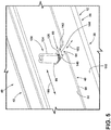
FIG. 5 is a rear top perspective view of the appliance and control panel assembly ofFIG. 4 showing a locating pin received in an inwardly opening slot; and -
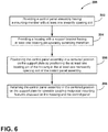
FIG. 6 is a flow chart showing a method of positioning and retaining a control panel assembly on an appliance. - The components in the figures are not necessarily to scale, emphasis instead being placed upon illustrating the principles described herein.
- The present illustrated embodiments reside primarily in combinations of method steps and apparatus components related to an alignment system for a console of an appliance. Accordingly, the apparatus components and method steps have been represented, where appropriate, by conventional symbols in the drawings, showing only those specific details that are pertinent to understanding the embodiments of the present disclosure so as not to obscure the disclosure with details that will be readily apparent to those of ordinary skill in the art having the benefit of the description herein. Further, like numerals in the description and drawings represent like elements.
- For purposes of description herein, the terms "upper," "lower," "right," "left," "rear," "front," "vertical," "horizontal," and derivatives thereof shall relate to the disclosure as oriented in
FIG. 1 . Unless stated otherwise, the term "front" shall refer to the surface of the element closer to an intended viewer, and the term "rear" shall refer to the surface of the element further from the intended viewer. However, it is to be understood that the disclosure may assume various alternative orientations, except where expressly specified to the contrary. It is also to be understood that the specific devices and processes illustrated in the attached drawings, and described in the following specification are simply exemplary embodiments of the inventive concepts defined in the appended claims. Hence, specific dimensions and other physical characteristics relating to the embodiments disclosed herein are not to be considered as limiting, unless the claims expressly state otherwise. - The terms "including," "comprises," "comprising," or any other variation thereof, are intended to cover a non-exclusive inclusion, such that a process, method, article, or apparatus that comprises a list of elements does not include only those elements but may include other elements not expressly listed or inherent to such process, method, article, or apparatus. An element proceeded by "comprises a ... " does not, without more constraints, preclude the existence of additional identical elements in the process, method, article, or apparatus that comprises the element.
- Referring to
FIG. 1 ,reference numeral 10 generally designates an appliance, shown in the form of a built-in oven, but may also include a range having an oven portion, a microwave oven, a toaster oven, a refrigerator or a laundry care appliance, such as a front loading washer or dryer. Theappliance 10 includes ahousing 12 having upper andlower sides second sidewalls housing 12 further includes arear panel 22 and anopen front portion 24. Theopen front portion 24 opens into acooking cavity 26 generally defined by the upper andlower sides second sidewalls housing 12. Thehousing 12 further includes aframe assembly 28 disposed around theopen front portion 24 of thehousing 12. Theframe assembly 28 includes asupport bracket 30, best shown inFIG. 3 that is positioned above thecooking cavity 26. Thesupport bracket 30 is interconnected at opposite sides thereof by first andsecond side members frame assembly 28. Theframe assembly 28 is shown inFIG. 1 as a front frame assembly, and may also include alower bracket 36 interconnecting the first andsecond side members - As further shown in
FIG. 1 , theappliance 10 includes acontrol panel assembly 40 that is mounted to thehousing 12. Specifically, thecontrol panel assembly 40 is supported on thesupport bracket 30 of theframe assembly 28 in a centered position, as further described below. In this way, thecontrol panel assembly 40 is mounted above thecooking cavity 26 in a centered position on thehousing 12, as shown inFIG. 1 . Thecontrol panel assembly 40 is mounted on a front portion of thehousing 12, such that thecontrol panel assembly 40 is easily accessible to a user of theappliance 10. Thecontrol panel assembly 40 defines a user interface console for theappliance 10, such that a user may control the features of theappliance 10 through thecontrol panel assembly 40, as further described below. Thecontrol panel assembly 40 may be referred to herein as a console or console assembly. Thecontrol panel assembly 40 includes amounting plate 42 with atrim member 100 mounted on themounting plate 42. Apane 90 is further mounted to themounting plate 42 and includes auser interface 80 mounted thereto. Both thecontrol panel assembly 40 and theuser interface 80 are centered on thehousing 12 and centered over thecooking cavity 26 of theappliance 10. - Referring now to
FIG. 2 , themounting plate 42 of thecontrol panel assembly 40 includes afront surface 44. Themounting plate 42 further includes anupper member 46 spaced-apart from amounting member 48 and interconnected by first andsecond side portions upper member 46, themounting member 48 and the first andsecond side portions window 54 that is generally centrally disposed on themounting plate 42. Themounting member 48 outwardly extends from thefront surface 44 of themounting plate 42 in a rearward direction. Themounting member 48 includes abody portion 56 having anouter edge 58. First andsecond slots body portion 56 and open inwardly from theouter edge 58 of thebody portion 56. The first andsecond slots second slots second slots outer edge 58 into thebody portion 56 at open front portion 64 (FIGS. 3 and5 ) of the first andsecond slots front surface 44 of themounting plate 42 from theouter edge 58 of thebody portion 56 towards the closed end portions 66 (FIGS. 3 and5 ) of the first andsecond slots mounting member 48 is a rearwardly extending mounting member having the first andsecond slots control panel assembly 40 on thehousing 12 of theappliance 10, as further described below. In the embodiment shown inFIG. 2 , themounting member 48 includes the first andsecond slots body portion 56 thereof. It is also contemplated that a single slot may be disposed on themounting member 48, without departing from the spirit of the present concept. - As further shown in
FIG. 2 , themounting plate 42 includes first andsecond mounting brackets lower mounting apertures body portions 76 thereof. The first andsecond mounting brackets mounting plate 42, such that the first andsecond mounting brackets front surface 44 of themounting plate 42 in a rearward direction. Specifically, the first and second mountingbrackets second sides control panel assembly 40, and rearwardly extend from thecontrol panel assembly 40, as shown in the assembled condition inFIG. 3 . As shown in the embodiment ofFIG. 2 , the first and second mountingbrackets member 48 on the mountingplate 42. It is contemplated that the first and second mountingbrackets plate 42 may include portions of a sheet metal substrate that remain after thewindow 54 is stamped into the mountingplate 42. After stamping thewindow 54, the portions of the sheet metal material can be bent rearwardly to define the first and second mountingbracket member 48. - As further shown in
FIG. 2 , theuser interface 80 of thecontrol panel assembly 40 includes first andsecond sides user interface 80 may include activation buttons, a display screen, a controller, and any other component parts necessary for a user to control the features of the appliance via theuser interface 80. Thus, theuser interface 80 is contemplated to be electronically coupled to a controller for controlling aspects of theappliance 10. With theappliance 10 shown in the form of an oven inFIG. 1 , it is contemplated that theuser interface 80 will include programming interface options for controlling aspects of thecooking cavity 26 and any heating element or heating features configured to heat thecooking cavity 26. Theuser interface 80 may include a digital interface that uses a touchscreen graphical user interface, or may include physical buttons and switches for controlling theappliance 10. - As further shown in
FIG. 2 , thepane 90 of thecontrol panel assembly 40 includes first andsecond surfaces pane 90 may be a glass pane or acrylic pane, through which theuser interface 80 can be controlled. In this way, thepane 90 may include a conductive touchscreen material that allows a user to operate theuser interface 80. In assembly, theuser interface 80 is mounted to thesecond surface 94 of thepane 90 at thefirst side 82 of theuser interface 80. Thepane 90 is contemplated to be mounted to the mountingplate 42 at thefront surface 44 of the mountingplate 42 at thesecond surface 94 of thepane 90. Theuser interface 80 is contemplated to be centered on thesecond surface 94 of thepane 90, such that theuser interface 80 can be centered on thecontrol panel assembly 40 in assembly, as best shown inFIGS. 3 and4 . Other positions for theuser interface 80 are also contemplated on thecontrol panel assembly 40. Thus, theuser interface 80 is mounted to the mountingplate 42 through thepane 90. - As further shown in
FIG. 2 , thecontrol panel assembly 40 includes atrim member 100 having upper andlower members second side members lower members second side members window 110 that is generally centrally disposed on thetrim member 100. Thetrim member 100 is contemplated to be mounted to thefirst surface 92 of thepane 90, and is further contemplated to be mounted to the mountingplate 42. Thetrim member 100 may further be mounted to thehousing 12 of theappliance 10 using mounting features 112, 114 and 116 extending outwardly from thelower member 104. With reference toFIG. 1 , thepane 90 is shown positioned within thewindow 110 defined by thetrim member 100. - Referring now to
FIG. 3 , thecontrol panel assembly 40 is shown in an assembled condition and exploded away from thehousing 12 of theappliance 10. InFIG. 3 , thesupport bracket 30 of theframe assembly 28 of thehousing 12 includes asupport surface 118 which defines an upper surface of thesupport bracket 30. Thesupport bracket 30 further includes first and second mountingapertures apertures support bracket 30, such that the first and second locating pins 130, 132 upwardly extend from thesupport surface 118 of thesupport bracket 30. The first and second locating pins 130, 132 are contemplated to be similar or identical in configuration, such that like reference numerals are used to describe common features of both the first and second locating pins 130, 132. The locating pins 130, 132 each includebody portions 134 that upwardly extend from thesupport surface 118 of thesupport bracket 30. In assembly, the first and second locating pins 130, 132 are configured to be horizontally received within the first andsecond slots control panel assembly 40 is mounted on thehousing 12 at thesupport bracket 30. InFIG. 3 , dashed lines are used to indicate the horizontal reception of the locating pins 130, 132 to the first andsecond slots second slots control panel assembly 40 to thehousing 12 of theappliance 10. Thus, the first andsecond slots control panel assembly 40 to thesupport bracket 30. - As further shown in
FIG. 3 , thehousing 12 of theappliance 10 further includes first and second mounting features 170, 172. The first and second mounting features 170, 172 are contemplated to be similar or identical in configuration, such that like reference numerals are used to describe common features shared between the first and second mounting features 170, 172. As shown inFIG. 3 , the first and second mounting features 170, 172 includebody portions 176 which upwardly extend from opposed first andsecond sides support bracket 30. Thebody portions 176 may be mounted to theframe assembly 28 at the first andsecond side members frame assembly 28. The first and second mounting features 170, 172 each include anupper mounting aperture 174A disposed above alower mounting slot 174B. In assembly, theupper mounting apertures 174A of the first and second mounting features 170, 172 of thehousing 12 are configured to align with theupper mounting apertures 74A of the first and second mountingbrackets slots 174B of the first and second mounting features 170, 172 of thehousing 12 are configured to align with the lower mountingapertures 74B of the first and second mountingbrackets control panel assembly 40 can be fixedly coupled to thehousing 12 after being centered on thesupport bracket 30 by the engagement of the first and second locating pins 130, 132 with the first andsecond slots control panel assembly 40. It is contemplated that the interconnection between the first and second mountingbrackets respective mounting apertures slots 174B thereof. Thelower mounting slots 174B of the first and second mounting features 170, 172 are oblong-shaped apertures which can accommodate variations in control panel and appliance components to provide for specific and consistent spacing between edges of thecontrol panel assembly 40 and adjacent edges of thehousing 12, or components thereof (such as an appliance door). - Referring now to
FIG. 4 , thecontrol panel assembly 40 is shown mounted to thehousing 12 at thesupport bracket 30 thereof. Specifically, the first and second locating pins 130, 132 are shown received within the first andsecond slots support bracket 30, and the first andsecond slots member 48 of the mountingplate 42, such that when the first and second locating pins 130, 132 are horizontally received within the first andsecond slots control panel assembly 40 is centered on thehousing 12 of theappliance 10. As further shown inFIG. 4 , theuser interface 80 is contemplated to be centered on thepane 90, such that theuser interface 80 is also centered on thehousing 12 of theappliance 10. The engagement between the first and second locating pins 130, 132 and the first andsecond slots control panel assembly 40 relative to thehousing 12. In this way, the engagement between the first and second locating pins 130, 132 and the first andsecond slots arrow 150. Once thecontrol panel assembly 40 is centered on thehousing 12 and laterally fixed in the centered position by the engagement between the first and second locating pins 130, 132 and the first andsecond slots control panel assembly 40 can be secured in the desired centered position by fixedly coupling the first and second mountingbrackets plate 42 to the first and second mounting features 170, 172 of thehousing 12. As noted above, the upper and lower mountingapertures brackets upper mounting apertures 174A and the lower mountingslots 174B of the first and second mounting features 170, 172. In this way, thecontrol panel assembly 40 is retained in the centered position on thehousing 12. - With further reference to
FIG. 4 , the first and second locating pins 130, 132 are shown received within the first andsecond slots second slots FIG. 4 along with two slots (first andsecond slots 60, 62), is contemplated that more slot and pin combinations may be included in the alignment system of the present concept for aligning thecontrol panel assembly 40 on thehousing 12. Further, it is contemplated that a single locating pin and slot combination may be provided as a locating feature for thecontrol panel assembly 40. - Referring now to
FIG. 5 , the locatingpin 130 is shown upwardly extending from thesupport surface 118 of thesupport bracket 30 through the mountingaperture 120. Specifically, the locatingpin 130 includes abody portion 134 that upwardly extends from thesupport surface 118 of thesupport bracket 30. The locatingpin 130 shown inFIG. 5 , and the other locating pins described herein, may include expanding clinch pin assemblies that can expand to fixedly engage the mountingaperture 120 to provide a fixed coupling between thesupport bracket 30 and the locatingpin 130. Again, as noted above, the locatingpin 130 is configured to be slidably, removably and horizontally received within theslot 60 in the direction as indicated byarrow 152. Thus, thebody portion 134 of the locatingpin 130 is received through theopen front portion 64 of theslot 60 in the horizontal manner as indicated byarrow 152 as the locatingpin 130 nears theclosed end portion 66 of theslot 60. It is not necessary that the locatingpin 130 be fully seated in theslot 60 in order to combat lateral movement in the direction as indicated byarrow 150. As further shown inFIG. 5 , theslot 60 includes first and secondinner edge portions distance 144 which is contemplated to closely received thebody portion 134 of the locatingpin 130 to resist lateral movement of thecontrol panel assembly 40 once the locatingpin 130 is received within theslot 60. However, thecontrol panel assembly 40 can be moved forward and rearward with the locatingpin 130 slidably received in theslot 60 to provide alignment between thecontrol panel assembly 40 and other features of theappliance 10. As noted above, reception of the locatingpin 130 within theslot 60 of the mountingmember 48 of the mountingplate 42 of thecontrol panel assembly 40 correlates to a centered position of thecontrol panel assembly 40 on thehousing 12, and may also correlate to a centered position of theuser interface 80 as mounted to thecontrol panel assembly 40. - The present concept further includes a
method 200 of mounting a control panel assembly to an appliance. Themethod 200 may comprise thestep 202 of providing a control panel assembly having a mounting member with at least one inwardly opening slot. The control panel assembly may include a control panel assembly similar to controlpanel assembly 40 described above having a mountingmember 48 with at least one inwardly opening slot, such as inwardly openingslots method 200 may further include thestep 204 of providing a housing with a support bracket having at least one locating pin upwardly extending therefrom. The housing provided in themethod 200 may include a housing similar tohousing 12 described above having thesupport bracket 30 with at least one locatingpin 130 extending upwardly therefrom. Themethod 200 may further include thestep 206 of positioning the control panel assembly in a centered position on the support plate by positioning the at least one locating pin of the housing in the at least one rearwardly opening slot of the control panel assembly, as discussed above with reference toFIGS. 3 and4 . Themethod 200 may further include thestep 208 of retaining the control panel assembly in the centered position on the support plate by operably coupling reciprocal mounting features disposed on the housing and the control panel assembly to one another after the control panel assembly is positioned in the centered position. The reciprocal mounting features provided in themethod 200 are contemplated to be mounting features such as the first and second mountingbrackets - According to one aspect of the present disclosure, an appliance includes a control panel assembly having a rearwardly extending mounting member. The rearwardly extending mounting member includes a body portion having an outer edge with one or more slots disposed through the body portion and inwardly opening from the outer edge of the body portion. A housing includes a support bracket having a support surface with one or more mounting apertures disposed therethrough. One or more locating pins are received through the one or more mounting apertures. The locating pins include body portions upwardly extending from the support surface of the support bracket. The one or more locating pins are removably received in the one or more slots of the rearwardly extending mounting member of the control panel assembly.
- According to another aspect of the present disclosure, the one or more locating pins and the one or more slots are positioned such that the control panel assembly is supported in a centered position on the housing when the one or more locating pins are removably received in the one or more slots.
- According to another aspect of the present disclosure, one or more mounting brackets are disposed on the control panel assembly and one or more mounting features are disposed on the housing. The one or more mounting brackets of the control panel assembly are operably coupled to the one or more mounting features of the housing to retain the control panel assembly in the centered position.
- According to another aspect of the present disclosure, the one or more mounting brackets include first and second mounting brackets spaced-apart from one another and rearwardly extending from the control panel assembly.
- According to another aspect of the present disclosure, the one or more locating pins are horizontally received in the one or more slots.
- According to another aspect of the present disclosure, the one or more locating pins include first and second locating pins.
- According to another aspect of the present disclosure, the one or more slots include first and second slots in which the first and second locating pins are respectively received.
- According to another aspect of the present disclosure, an appliance includes a housing with a frame assembly having a support bracket. The support bracket includes at least one locating pin. A mounting plate includes a front surface with a mounting member outwardly extending from the front surface of the mounting plate. The mounting member includes at least one slot through which the at least one locating pin is slidably received.
- According to another aspect of the present disclosure, the appliance includes a user interface mounted on the mounting plate.
- According to another aspect of the present disclosure, the at least one locating pin and the at least one slot are respectively positioned on the support bracket and the mounting member, such that the user interface is supported in a centered position on the support bracket when the at least one locating pin is received in the at least one slot.
- According to another aspect of the present disclosure, first and second mounting brackets are disposed above the mounting member and outwardly extending from the front surface of the mounting plate.
- According to another aspect of the present disclosure, first and second mounting features are disposed on the housing on opposed sides of the support bracket, respectively. The first and second mounting brackets are operably coupled to the first and second mounting features, respectively, to retain the user interface in the centered position.
- According to another aspect of the present disclosure, the mounting member includes a body portion having an outer edge. The at least one slot of the mounting member inwardly opens into the body portion from the outer edge of the body portion.
- According to another aspect of the present disclosure, the at least one locating pin includes a body portion upwardly extending from an upper surface of the support bracket. The body portion of the at least one locating pin is configured to be horizontally received in the at least one slot.
- According to another aspect of the present disclosure, the housing includes a cooking cavity disposed below the support bracket. The mounting plate includes a user interface mounted thereto to define a control panel assembly.
- According to another aspect of the present disclosure, a method of mounting a control panel assembly to an appliance comprises the steps of: (1) providing a control panel assembly having a mounting member with at least one slot (2) providing a housing with a support bracket having at least one locating pin upwardly extending therefrom (3) positioning the control panel assembly in a centered position on the support plate by positioning the at least one locating pin of the housing in the at least one slot of the control panel assembly (4) retaining the control panel assembly in the centered position on the support plate by operably coupling reciprocal mounting features disposed on the housing and the control panel assembly to one another after the control panel assembly is positioned in the centered position.
- According to another aspect of the present disclosure, the step of positioning the at least one locating pin of the housing in the at least one slot further includes, horizontally and slidably receiving the locating pin in the at least one slot.
- According to another aspect of the present disclosure, the mounting member includes an outer edge and further wherein the at least one slot opens from the outer edge of the mounting member.
- According to another aspect of the present disclosure, the step of operably coupling reciprocal mounting features disposed on the housing and the control panel assembly to one another further includes, fastening first and second mounting brackets of the control panel assembly to first and second mounting features disposed on the housing on opposed sides of the support bracket.
- According to another aspect of the present disclosure, the step of positioning the at least one locating pin of the housing in the at least one slot further includes, positioning first and second locating pins of the housing in first and second slots of the mounting member respectively.
- According to one aspect of the present disclosure, an appliance includes a control panel assembly having a rearwardly extending mounting member. The rearwardly extending mounting member includes a body portion having an outer edge with one or more slots disposed through the body portion and inwardly opening from the outer edge of the body portion. A housing includes a support bracket having a support surface with one or more mounting apertures disposed therethrough. One or more locating pins are received through the one or more mounting apertures. The locating pins include body portions upwardly extending from the support surface of the support bracket. The one or more locating pins are removably received in the one or more slots of the rearwardly extending mounting member of the control panel assembly.
- According to another aspect of the present disclosure, the one or more locating pins and the one or more slots are positioned such that the control panel assembly is supported in a centered position on the housing when the one or more locating pins are removably received in the one or more slots.
- According to another aspect of the present disclosure, one or more mounting brackets are disposed on the control panel assembly and rearwardly extend therefrom.
- According to another aspect of the present disclosure, one or more mounting features are disposed on the housing. The one or more mounting brackets of the control panel assembly are operably coupled to the one or more mounting features of the housing to retain the control panel assembly in the centered position.
- According to another aspect of the present disclosure, the one or more mounting features include a first mounting feature and a second mounting feature disposed on opposed first and second sides, respectively, of the support bracket.
- According to another aspect of the present disclosure, the one or more mounting brackets include a first mounting bracket and a second mounting bracket disposed on opposed first and second sides, respectively, of the control panel assembly.
- According to another aspect of the present disclosure, the one or more locating pins include a first locating pin and a second locating pin.
- According to another aspect of the present disclosure, the one or more slots include a first slot and a second slot. The first locating pin is received in the first slot and the second locating pin is received in the second slot.
- According to another aspect of the present disclosure, the one or more locating pins are horizontally received in the one or more slots.
- According to another aspect of the present disclosure, the control panel assembly (40) includes a mounting plate having an upper member spaced-apart from the mounting member and interconnected by first and second side portions.
- According to another aspect of the present disclosure, the upper member, the mounting member and the first and second side portions cooperate to surround and define a window that is generally centrally disposed on the mounting plate.
- According to another aspect of the present disclosure, a pane includes first and second surfaces and is received in the window of the mounting plate.
- According to another aspect of the present disclosure, a user interface is operably coupled to the second surface of the pane.
- According to another aspect of the present disclosure, a trim member is mounted to the first surface of the pane and is also coupled to the mounting plate.
- According to another aspect of the present disclosure, the user interface is centered on the control panel assembly.
Claims (15)
- An appliance (10), comprising:a control panel assembly (40) having a rearwardly extending mounting member (48), wherein the rearwardly extending mounting member (48) includes a body portion (56) having an outer edge (58) with one or more slots (60, 62) disposed through the body portion (56) and inwardly opening from the outer edge (58) of the body portion (56);a housing (12) having a support bracket (30), wherein the support bracket (30) includes a support surface (118) with one or more mounting apertures (120, 122) disposed therethrough; andone or more locating pins (130, 132) received through the one or more mounting apertures (120, 122), wherein the one or more locating pins (130, 132) include body portions (134) upwardly extending from the support surface (118) of the support bracket (30), and further wherein the one or more locating pins (130, 132) are removably received in the one or more slots (60, 62) of the rearwardly extending mounting member (48) of the control panel assembly (40).
- The appliance (10) of claim 1, wherein the one or more locating pins (130, 132) and the one or more slots (60, 62) are positioned such that the control panel assembly (40) assembly is supported in a centered position on the housing (12) when the one or more locating pins (130, 132) are removably received in the one or more slots (60, 62).
- The appliance (10) of claim 2, including:
one or more mounting brackets (70, 72) disposed on the control panel assembly (40) assembly and rearwardly extending therefrom. - The appliance (10) of claim 3, including:
one or more mounting features (170, 172) disposed on the housing (12), wherein the one or more mounting brackets (70, 72) of the control panel assembly (40) assembly are operably coupled to the one or more mounting features (170, 172) of the housing (12) to retain the control panel assembly (40) assembly in the centered position. - The appliance (10) of claim 4, wherein the one or more mounting features (170, 172) include a first mounting feature (170) and a second mounting feature (172) disposed on opposed first and second sides (30A, 30B), respectively, of the support bracket (30).
- The appliance (10) of claim 5, wherein the one or more mounting brackets (70, 72) include a first mounting bracket (70) and a second mounting bracket (72) disposed on opposed first and second sides (40A, 40B), respectively, of the control panel assembly (40).
- The appliance (10) of claim 1, wherein the one or more locating pins (130, 132) include a first locating pin (130) and a second locating pin (132).
- The appliance (10) of claim 7, wherein the one or more slots (60, 62) include a first slot (60) and a second slot (62), and further wherein the first locating pin (130) is received in the first slot (60) and the second locating pin (132) is received in the second slot (62).
- The appliance (10) of claim 8, wherein the first locating pin (130) and the second locating pin (132) are horizontally received in the first slot (60) and the second slot (62), respectively.
- The appliance (10) of claim 1, wherein the control panel assembly (40) includes a mounting plate (42) having an upper member (46) spaced-apart from the mounting member (48) and interconnected by first and second side portions (50, 52).
- The appliance (10) of claim 10, wherein the upper member (46), the mounting member (48) and the first and second side portions (50, 52) cooperate to surround and define a window (54) that is generally centrally disposed on the mounting plate (42).
- The appliance (10) of claim 11, including:
a pane (90) having first and second surfaces (92, 94), wherein the pane (90) is received in the window (54) of the mounting plate (42). - The appliance (10) of claim 12, including:
a user interface (80) operably coupled to the second surface (94) of the pane (90). - The appliance (10) of claim 13, including:
a trim member (100) mounted to the first surface (92) of the pane (90) and further coupled to the mounting plate (42). - The appliance (10) of any one of claims 13 and 14, wherein the user interface (80) is centered on the control panel assembly (40).
Applications Claiming Priority (1)
| Application Number | Priority Date | Filing Date | Title |
|---|---|---|---|
| US16/812,453 US11019746B1 (en) | 2020-03-09 | 2020-03-09 | Lateral alignment system for an appliance control panel assembly and method |
Publications (1)
| Publication Number | Publication Date |
|---|---|
| EP3879180A1 true EP3879180A1 (en) | 2021-09-15 |
Family
ID=74758540
Family Applications (1)
| Application Number | Title | Priority Date | Filing Date |
|---|---|---|---|
| EP21159114.4A Withdrawn EP3879180A1 (en) | 2020-03-09 | 2021-02-24 | Appliance comprising control panel assembly |
Country Status (2)
| Country | Link |
|---|---|
| US (1) | US11019746B1 (en) |
| EP (1) | EP3879180A1 (en) |
Cited By (1)
| Publication number | Priority date | Publication date | Assignee | Title |
|---|---|---|---|---|
| EP4317806A1 (en) * | 2022-08-02 | 2024-02-07 | LG Electronics Inc. | Cooking appliance |
Families Citing this family (2)
| Publication number | Priority date | Publication date | Assignee | Title |
|---|---|---|---|---|
| US10586471B1 (en) * | 2016-12-29 | 2020-03-10 | VCE IP Holding Company LLC | Universal branding panel |
| US12429228B2 (en) * | 2022-03-15 | 2025-09-30 | Whirlpool Corporation | Console assembly and method for assembling a console assembly of a cooking appliance |
Citations (7)
| Publication number | Priority date | Publication date | Assignee | Title |
|---|---|---|---|---|
| US3402281A (en) * | 1965-10-08 | 1968-09-17 | Tappan Co | Range construction |
| DE8134827U1 (en) * | 1981-11-28 | 1982-12-02 | Licentia Patent-Verwaltungs-Gmbh, 6000 Frankfurt | Switch panel with decorative inlay for household appliances |
| FR2862109A1 (en) * | 2003-11-07 | 2005-05-13 | Renault Sas | DEVICE FOR FIXING PARTS OF MOTOR VEHICLES. |
| DE102005024934A1 (en) * | 2005-05-31 | 2006-12-07 | BSH Bosch und Siemens Hausgeräte GmbH | A method for indicating the selection options for a domestic appliance has a sandwich of transparent layers carrying universal and language data separately around the control knob |
| EP2390577A1 (en) * | 2010-05-28 | 2011-11-30 | Electrolux Home Products Corporation N.V. | User interface and appliance of household or industrial type, especially domestic appliance |
| CN207019132U (en) * | 2017-05-27 | 2018-02-16 | 杭州老板电器股份有限公司 | A kind of fast positioning and dismountable switch combination mounting structure |
| CN108797047A (en) * | 2017-04-28 | 2018-11-13 | 青岛海尔洗衣机有限公司 | A kind of dryer attachment device |
Family Cites Families (18)
| Publication number | Priority date | Publication date | Assignee | Title |
|---|---|---|---|---|
| US4894493A (en) | 1988-11-04 | 1990-01-16 | General Electric Company | Membrane touch control panel assembly for an appliance with a glass control panel |
| US5738424A (en) * | 1995-04-04 | 1998-04-14 | General Electric Company | Appliance backsplash assembly |
| US5685623A (en) * | 1995-04-04 | 1997-11-11 | General Electric Company | Appliance top assembly |
| US5611610A (en) * | 1995-04-04 | 1997-03-18 | General Electric Company | Control housing |
| DE19747769C2 (en) * | 1997-10-29 | 1999-12-16 | Bsh Bosch Siemens Hausgeraete | Household appliance with front panel |
| US5971510A (en) | 1998-01-22 | 1999-10-26 | Maytag Corporation | Appliance console attachment |
| US6371583B1 (en) | 2000-05-01 | 2002-04-16 | Whirpool Corporation | Screwless appliance console attachment |
| FR2911970B1 (en) | 2007-01-25 | 2009-10-02 | Dav Sa | ELECTRICAL CONTROL DEVICE |
| EP2458060B1 (en) * | 2010-11-29 | 2016-02-17 | Electrolux Home Products Corporation N.V. | Control-panel assembly for household appliances and household appliance provided with such control-panel assembly |
| DE102011079229B4 (en) | 2011-07-15 | 2022-11-10 | BSH Hausgeräte GmbH | Control panel, household appliance and method for producing a control panel |
| US9513013B2 (en) | 2011-07-28 | 2016-12-06 | Bsh Home Appliances Corporation | Manifold assembly for a domestic kitchen appliance |
| US9220394B2 (en) * | 2013-08-15 | 2015-12-29 | Whirlpool Corporation | LED console assembly with light reflector |
| KR101662941B1 (en) * | 2015-02-05 | 2016-10-05 | 엘지전자 주식회사 | Cooking apparatus and touch sensor assembly for cooking apparatus |
| US9732963B2 (en) * | 2015-06-17 | 2017-08-15 | Haier Us Appliance Solutions, Inc. | Appliance control panel assembly |
| KR102559759B1 (en) * | 2016-10-05 | 2023-07-26 | 삼성전자주식회사 | Control Panel and Household Appliance Having the same |
| CN208954024U (en) * | 2018-12-11 | 2019-06-07 | 勤诚兴业股份有限公司 | Separator, hard disk fixing mechanism and server |
| US10801732B2 (en) * | 2019-02-25 | 2020-10-13 | Haier Us Appliance Solutions, Inc. | Control console assembly for a cooking appliance |
| US11739940B2 (en) * | 2019-07-09 | 2023-08-29 | Bsh Home Appliances Corporation | Cooking appliance having a removable control panel |
-
2020
- 2020-03-09 US US16/812,453 patent/US11019746B1/en active Active
-
2021
- 2021-02-24 EP EP21159114.4A patent/EP3879180A1/en not_active Withdrawn
Patent Citations (8)
| Publication number | Priority date | Publication date | Assignee | Title |
|---|---|---|---|---|
| US3402281A (en) * | 1965-10-08 | 1968-09-17 | Tappan Co | Range construction |
| DE8134827U1 (en) * | 1981-11-28 | 1982-12-02 | Licentia Patent-Verwaltungs-Gmbh, 6000 Frankfurt | Switch panel with decorative inlay for household appliances |
| FR2862109A1 (en) * | 2003-11-07 | 2005-05-13 | Renault Sas | DEVICE FOR FIXING PARTS OF MOTOR VEHICLES. |
| DE102005024934A1 (en) * | 2005-05-31 | 2006-12-07 | BSH Bosch und Siemens Hausgeräte GmbH | A method for indicating the selection options for a domestic appliance has a sandwich of transparent layers carrying universal and language data separately around the control knob |
| EP2390577A1 (en) * | 2010-05-28 | 2011-11-30 | Electrolux Home Products Corporation N.V. | User interface and appliance of household or industrial type, especially domestic appliance |
| EP2390577B1 (en) * | 2010-05-28 | 2013-07-10 | Electrolux Home Products Corporation N.V. | Method of mounting a user interface for an appliance of household or industrial type |
| CN108797047A (en) * | 2017-04-28 | 2018-11-13 | 青岛海尔洗衣机有限公司 | A kind of dryer attachment device |
| CN207019132U (en) * | 2017-05-27 | 2018-02-16 | 杭州老板电器股份有限公司 | A kind of fast positioning and dismountable switch combination mounting structure |
Cited By (1)
| Publication number | Priority date | Publication date | Assignee | Title |
|---|---|---|---|---|
| EP4317806A1 (en) * | 2022-08-02 | 2024-02-07 | LG Electronics Inc. | Cooking appliance |
Also Published As
| Publication number | Publication date |
|---|---|
| US11019746B1 (en) | 2021-05-25 |
Similar Documents
| Publication | Publication Date | Title |
|---|---|---|
| US11019746B1 (en) | Lateral alignment system for an appliance control panel assembly and method | |
| US5893359A (en) | Arrangement for assembling and mounting a built-in cooktop | |
| US20160334113A1 (en) | Cooking appliance | |
| US12121147B2 (en) | Mounting bracket for over-the-range cooking appliance with drill guide | |
| US9372003B2 (en) | Spring clip attachment for a surface cooking module of a household cooking appliance | |
| US12366365B2 (en) | Mounting bracket for over-the-range cooking appliance | |
| US20190063130A1 (en) | Oven | |
| US5859410A (en) | Mounting system for radiant cooktop heating elements | |
| US5847364A (en) | Radiant heater support system | |
| EP2204486B1 (en) | Electrical home appliance with top cover | |
| US12061000B2 (en) | Door assembly of an appliance having one or more assembly aids | |
| KR20180037700A (en) | Control Panel and Household Appliance Having the same | |
| US6512214B2 (en) | Apparatus for suspending microwave oven | |
| EP1647775A2 (en) | Oven with glass supporting structure | |
| US20240060651A1 (en) | Cooking appliance | |
| US12553616B2 (en) | Door latch for an appliance | |
| US7435932B2 (en) | Control unit of oven | |
| KR20030067256A (en) | Top cover fix structure of air conditioner | |
| KR100395944B1 (en) | Fastening Structure of Metal Control Panel in Microwave Oven | |
| US12631341B2 (en) | Cooking appliance | |
| KR100395641B1 (en) | Microwave oven | |
| US12432823B2 (en) | Electric cooktop assembly | |
| CN219693338U (en) | Cooking bench chassis mechanism and embedded cooking bench | |
| KR200349531Y1 (en) | A conclusion structure of controlplate for Electric oven | |
| US20230119872A1 (en) | Cooking appliance |
Legal Events
| Date | Code | Title | Description |
|---|---|---|---|
| PUAI | Public reference made under article 153(3) epc to a published international application that has entered the european phase |
Free format text: ORIGINAL CODE: 0009012 |
|
| STAA | Information on the status of an ep patent application or granted ep patent |
Free format text: STATUS: THE APPLICATION HAS BEEN PUBLISHED |
|
| AK | Designated contracting states |
Kind code of ref document: A1 Designated state(s): AL AT BE BG CH CY CZ DE DK EE ES FI FR GB GR HR HU IE IS IT LI LT LU LV MC MK MT NL NO PL PT RO RS SE SI SK SM TR |
|
| STAA | Information on the status of an ep patent application or granted ep patent |
Free format text: STATUS: REQUEST FOR EXAMINATION WAS MADE |
|
| 17P | Request for examination filed |
Effective date: 20220314 |
|
| RBV | Designated contracting states (corrected) |
Designated state(s): AL AT BE BG CH CY CZ DE DK EE ES FI FR GB GR HR HU IE IS IT LI LT LU LV MC MK MT NL NO PL PT RO RS SE SI SK SM TR |
|
| GRAP | Despatch of communication of intention to grant a patent |
Free format text: ORIGINAL CODE: EPIDOSNIGR1 |
|
| STAA | Information on the status of an ep patent application or granted ep patent |
Free format text: STATUS: GRANT OF PATENT IS INTENDED |
|
| INTG | Intention to grant announced |
Effective date: 20241220 |
|
| STAA | Information on the status of an ep patent application or granted ep patent |
Free format text: STATUS: THE APPLICATION IS DEEMED TO BE WITHDRAWN |
|
| 18D | Application deemed to be withdrawn |
Effective date: 20250423 |