EP3879151A1 - Valve device and assembly method therefor - Google Patents
Valve device and assembly method therefor Download PDFInfo
- Publication number
- EP3879151A1 EP3879151A1 EP19881846.0A EP19881846A EP3879151A1 EP 3879151 A1 EP3879151 A1 EP 3879151A1 EP 19881846 A EP19881846 A EP 19881846A EP 3879151 A1 EP3879151 A1 EP 3879151A1
- Authority
- EP
- European Patent Office
- Prior art keywords
- valve
- flow channel
- projecting portions
- pair
- valve body
- Prior art date
- Legal status (The legal status is an assumption and is not a legal conclusion. Google has not performed a legal analysis and makes no representation as to the accuracy of the status listed.)
- Granted
Links
Images


Classifications
-
- F—MECHANICAL ENGINEERING; LIGHTING; HEATING; WEAPONS; BLASTING
- F16—ENGINEERING ELEMENTS AND UNITS; GENERAL MEASURES FOR PRODUCING AND MAINTAINING EFFECTIVE FUNCTIONING OF MACHINES OR INSTALLATIONS; THERMAL INSULATION IN GENERAL
- F16K—VALVES; TAPS; COCKS; ACTUATING-FLOATS; DEVICES FOR VENTING OR AERATING
- F16K11/00—Multiple-way valves, e.g. mixing valves; Pipe fittings incorporating such valves
- F16K11/02—Multiple-way valves, e.g. mixing valves; Pipe fittings incorporating such valves with all movable sealing faces moving as one unit
- F16K11/08—Multiple-way valves, e.g. mixing valves; Pipe fittings incorporating such valves with all movable sealing faces moving as one unit comprising only taps or cocks
- F16K11/087—Multiple-way valves, e.g. mixing valves; Pipe fittings incorporating such valves with all movable sealing faces moving as one unit comprising only taps or cocks with spherical plug
- F16K11/0873—Multiple-way valves, e.g. mixing valves; Pipe fittings incorporating such valves with all movable sealing faces moving as one unit comprising only taps or cocks with spherical plug the plug being only rotatable around one spindle
-
- F—MECHANICAL ENGINEERING; LIGHTING; HEATING; WEAPONS; BLASTING
- F16—ENGINEERING ELEMENTS AND UNITS; GENERAL MEASURES FOR PRODUCING AND MAINTAINING EFFECTIVE FUNCTIONING OF MACHINES OR INSTALLATIONS; THERMAL INSULATION IN GENERAL
- F16K—VALVES; TAPS; COCKS; ACTUATING-FLOATS; DEVICES FOR VENTING OR AERATING
- F16K27/00—Construction of housing; Use of materials therefor
- F16K27/10—Welded housings
-
- F—MECHANICAL ENGINEERING; LIGHTING; HEATING; WEAPONS; BLASTING
- F16—ENGINEERING ELEMENTS AND UNITS; GENERAL MEASURES FOR PRODUCING AND MAINTAINING EFFECTIVE FUNCTIONING OF MACHINES OR INSTALLATIONS; THERMAL INSULATION IN GENERAL
- F16K—VALVES; TAPS; COCKS; ACTUATING-FLOATS; DEVICES FOR VENTING OR AERATING
- F16K27/00—Construction of housing; Use of materials therefor
- F16K27/06—Construction of housing; Use of materials therefor of taps or cocks
- F16K27/067—Construction of housing; Use of materials therefor of taps or cocks with spherical plugs
-
- F—MECHANICAL ENGINEERING; LIGHTING; HEATING; WEAPONS; BLASTING
- F16—ENGINEERING ELEMENTS AND UNITS; GENERAL MEASURES FOR PRODUCING AND MAINTAINING EFFECTIVE FUNCTIONING OF MACHINES OR INSTALLATIONS; THERMAL INSULATION IN GENERAL
- F16K—VALVES; TAPS; COCKS; ACTUATING-FLOATS; DEVICES FOR VENTING OR AERATING
- F16K27/00—Construction of housing; Use of materials therefor
- F16K27/12—Covers for housings
-
- F—MECHANICAL ENGINEERING; LIGHTING; HEATING; WEAPONS; BLASTING
- F16—ENGINEERING ELEMENTS AND UNITS; GENERAL MEASURES FOR PRODUCING AND MAINTAINING EFFECTIVE FUNCTIONING OF MACHINES OR INSTALLATIONS; THERMAL INSULATION IN GENERAL
- F16K—VALVES; TAPS; COCKS; ACTUATING-FLOATS; DEVICES FOR VENTING OR AERATING
- F16K31/00—Actuating devices; Operating means; Releasing devices
- F16K31/02—Actuating devices; Operating means; Releasing devices electric; magnetic
- F16K31/04—Actuating devices; Operating means; Releasing devices electric; magnetic using a motor
- F16K31/041—Actuating devices; Operating means; Releasing devices electric; magnetic using a motor for rotating valves
-
- F—MECHANICAL ENGINEERING; LIGHTING; HEATING; WEAPONS; BLASTING
- F16—ENGINEERING ELEMENTS AND UNITS; GENERAL MEASURES FOR PRODUCING AND MAINTAINING EFFECTIVE FUNCTIONING OF MACHINES OR INSTALLATIONS; THERMAL INSULATION IN GENERAL
- F16K—VALVES; TAPS; COCKS; ACTUATING-FLOATS; DEVICES FOR VENTING OR AERATING
- F16K37/00—Special means in or on valves or other cut-off apparatus for indicating or recording operation thereof, or for enabling an alarm to be given
- F16K37/0025—Electrical or magnetic means
- F16K37/0041—Electrical or magnetic means for measuring valve parameters
-
- F—MECHANICAL ENGINEERING; LIGHTING; HEATING; WEAPONS; BLASTING
- F16—ENGINEERING ELEMENTS AND UNITS; GENERAL MEASURES FOR PRODUCING AND MAINTAINING EFFECTIVE FUNCTIONING OF MACHINES OR INSTALLATIONS; THERMAL INSULATION IN GENERAL
- F16K—VALVES; TAPS; COCKS; ACTUATING-FLOATS; DEVICES FOR VENTING OR AERATING
- F16K5/00—Plug valves; Taps or cocks comprising only cut-off apparatus having at least one of the sealing faces shaped as a more or less complete surface of a solid of revolution, the opening and closing movement being predominantly rotary
- F16K5/06—Plug valves; Taps or cocks comprising only cut-off apparatus having at least one of the sealing faces shaped as a more or less complete surface of a solid of revolution, the opening and closing movement being predominantly rotary with plugs having spherical surfaces; Packings therefor
- F16K5/0626—Easy mounting or dismounting means
- F16K5/0636—Easy mounting or dismounting means the spherical plug being insertable from the top of the housing
-
- F—MECHANICAL ENGINEERING; LIGHTING; HEATING; WEAPONS; BLASTING
- F16—ENGINEERING ELEMENTS AND UNITS; GENERAL MEASURES FOR PRODUCING AND MAINTAINING EFFECTIVE FUNCTIONING OF MACHINES OR INSTALLATIONS; THERMAL INSULATION IN GENERAL
- F16L—PIPES; JOINTS OR FITTINGS FOR PIPES; SUPPORTS FOR PIPES, CABLES OR PROTECTIVE TUBING; MEANS FOR THERMAL INSULATION IN GENERAL
- F16L55/00—Devices or appurtenances for use in, or in connection with, pipes or pipe systems
- F16L55/10—Means for stopping flow in pipes or hoses
- F16L55/11—Plugs
- F16L55/1116—Plugs glued or welded
-
- F—MECHANICAL ENGINEERING; LIGHTING; HEATING; WEAPONS; BLASTING
- F16—ENGINEERING ELEMENTS AND UNITS; GENERAL MEASURES FOR PRODUCING AND MAINTAINING EFFECTIVE FUNCTIONING OF MACHINES OR INSTALLATIONS; THERMAL INSULATION IN GENERAL
- F16K—VALVES; TAPS; COCKS; ACTUATING-FLOATS; DEVICES FOR VENTING OR AERATING
- F16K27/00—Construction of housing; Use of materials therefor
- F16K27/10—Welded housings
- F16K27/107—Welded housings for taps or cocks
-
- F—MECHANICAL ENGINEERING; LIGHTING; HEATING; WEAPONS; BLASTING
- F16—ENGINEERING ELEMENTS AND UNITS; GENERAL MEASURES FOR PRODUCING AND MAINTAINING EFFECTIVE FUNCTIONING OF MACHINES OR INSTALLATIONS; THERMAL INSULATION IN GENERAL
- F16K—VALVES; TAPS; COCKS; ACTUATING-FLOATS; DEVICES FOR VENTING OR AERATING
- F16K31/00—Actuating devices; Operating means; Releasing devices
- F16K31/44—Mechanical actuating means
- F16K31/53—Mechanical actuating means with toothed gearing
- F16K31/535—Mechanical actuating means with toothed gearing for rotating valves
-
- Y—GENERAL TAGGING OF NEW TECHNOLOGICAL DEVELOPMENTS; GENERAL TAGGING OF CROSS-SECTIONAL TECHNOLOGIES SPANNING OVER SEVERAL SECTIONS OF THE IPC; TECHNICAL SUBJECTS COVERED BY FORMER USPC CROSS-REFERENCE ART COLLECTIONS [XRACs] AND DIGESTS
- Y10—TECHNICAL SUBJECTS COVERED BY FORMER USPC
- Y10T—TECHNICAL SUBJECTS COVERED BY FORMER US CLASSIFICATION
- Y10T137/00—Fluid handling
- Y10T137/0318—Processes
- Y10T137/0402—Cleaning, repairing, or assembling
- Y10T137/0491—Valve or valve element assembling, disassembling, or replacing
- Y10T137/0508—Ball valve or rotary ball valve
-
- Y—GENERAL TAGGING OF NEW TECHNOLOGICAL DEVELOPMENTS; GENERAL TAGGING OF CROSS-SECTIONAL TECHNOLOGIES SPANNING OVER SEVERAL SECTIONS OF THE IPC; TECHNICAL SUBJECTS COVERED BY FORMER USPC CROSS-REFERENCE ART COLLECTIONS [XRACs] AND DIGESTS
- Y10—TECHNICAL SUBJECTS COVERED BY FORMER USPC
- Y10T—TECHNICAL SUBJECTS COVERED BY FORMER US CLASSIFICATION
- Y10T137/00—Fluid handling
- Y10T137/598—With repair, tapping, assembly, or disassembly means
- Y10T137/6031—Assembling or disassembling rotary valve
- Y10T137/6035—Rotary ball valve
Definitions
- the present invention relates to a valve device that includes tubular flow channels and a method for assembling the valve device.
- the flow channel switching valve includes a valve body that has a valve chamber, a ball-like valve member that is disposed in the valve chamber, a valve shaft that is coupled with the valve member, and a rotation driving section that includes, for example, a drive gear and a motor that rotationally drives the valve member via the valve shaft.
- Patent Literature 1 JP 2018-115690 A
- the shape of a tubular flow channel connected to a valve body may be changed so as to be suitable for a system into which the flow channel switching valve is incorporated.
- three ports as flow channels that have a circular tube shape are each formed so as to linearly extend from the valve body.
- a flow channel for example, formed in an L-shape may be used in some cases where a hose that is connected to the flow channel is directed to a certain direction.
- the L-shaped flow channel includes a first portion that linearly extends from the valve body and a second portion that serves as a hose joint that is connected perpendicular to the first portion.
- a tip end of the first portion has an opening for extracting a core of a mold, and a lid member that covers the opening is joined to the tip end of the first portion.
- the lid member is joined in a manner in which the lid member is stacked on the tip end of the first portion, the first portion or a portion that is further from the lid member than the first portion is supported by a jig, and an ultrasonic vibration is applied to the lid member for welding.
- a planar surface that is, a planar surface that faces in the opposite direction from the tip end of the first portion
- the valve body has such a planar surface. Accordingly, the distance between a portion that is supported by the jig and a portion that is welded is long, and there is a possibility that the efficiency of ultrasonic welding decreases.
- a connection between the first portion and the second portion damages and deforms due to force that is applied thereto when the hose is mounted on the second portion.
- a valve device includes a valve body that has a valve chamber, tubular flow channels that are in communication with the valve chamber and that are connected to the valve body, and a valve member that is installed in the valve chamber and that switches between connections of the flow channels.
- At least one flow channel of the flow channels includes a first portion that is connected to the valve body and that is linear, a second portion that is connected at an angle to the first portion and that is linear, a lid member that is joined such that the lid member covers an opening of a tip end of the first portion, and a pair of projecting portions that is disposed such that the projecting portions interpose the first portion therebetween in a radial direction and face each other and that extends from an outer circumferential surface of the first portion to an outer circumferential surface of the second portion.
- the pair of projecting portions preferably includes a planar surface portion that faces the valve body direction.
- a connecting portion that extends in a circumferential direction on the outer circumferential surface of the first portion such that the connecting portion couples the pair of projecting portions with each other is preferably further included.
- the pair of projecting portions preferably protrudes toward a tip end of the second portion and is arranged nearer the tip end of the second portion than the first portion when viewed in an axial direction of the first portion.
- a method for assembling a valve device is a method for assembling a valve device that includes a valve body that has a valve chamber, tubular flow channels that are in communication with the valve chamber and that are connected to the valve body, and a valve member that is installed in the valve chamber and that switches between connections of the flow channels, at least one flow channel of the flow channels including a first portion that is connected to the valve body and that is linear and a second portion that is connected at an angle to the first portion and that is linear.
- the method includes supporting a planar surface portion that faces the valve body direction and that is included in a pair of projecting portions that is disposed such that the projecting portions interpose the first portion therebetween in a radial direction and face each other and that extends from an outer circumferential surface of the first portion to an outer circumferential surface of the second portion; and stacking a lid member on an opening of a tip end of the first portion and welding the lid member to the first portion by applying an ultrasonic vibration to the lid member.
- At least one flow channel of the flow channels includes the first portion that is connected to the valve body and that is linear, the second portion that is connected at an angle to the first portion and that is linear, the lid member that is joined such that the lid member covers the opening of the tip end of the first portion, and the pair of projecting portions that is disposed such that the projecting portions interpose the first portion therebetween in the radial direction and face each other and that extends from the outer circumferential surface of the first portion to the outer circumferential surface of the second portion.
- the lid member can be welded by ultrasonic welding with the pair of projecting portions supported. Accordingly, the efficiency of ultrasonic welding can be inhibited from decreasing because the pair of projecting portions is relatively near a welded portion.
- the pair of projecting portions extends from the outer circumferential surface of the first portion to the outer circumferential surface of the second portion, parts on which the projecting portions are disposed have a thickness greater than that of the other part, and the rigidity of a connection between the first portion and the second portion can be increased. Accordingly, the efficiency of ultrasonic welding for the flow channel can be effectively inhibited from decreasing, and the rigidity of the flow channel can be increased. Since the pair of projecting portions includes the planar surface portion that faces the valve body direction, the pair of projecting portions can be stably supported.
- the rigidity of the connection between the first portion and the second portion can be further increased.
- the hose Since the pair of projecting portions protrudes toward the tip end of the second portion and is arranged nearer the tip end of the second portion than the first portion when viewed in the axial direction of the first portion, the hose is brought into contact with the end surfaces of the pair of projecting portions that face the tip end of the second portion, and the projecting portions can function as a positioning stopper for the hose.
- a flow channel switching valve corresponding to a valve device according to an embodiment of the present invention will now be described with reference to FIG. 1 to FIGs. 7 .
- FIG. 1 is a perspective view of the flow channel switching valve according to the embodiment of the present invention.
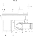
- FIG. 2 is a left side view of the flow channel switching valve in FIG. 1 .
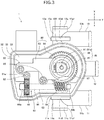
- FIG. 3 is a plan view of the flow channel switching valve in FIG. 1 with an upper wall portion of a gear case portion removed.
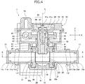
- FIG. 4 is a cross-sectional view (a vertical cross-sectional view) of the flow channel switching valve in FIG. 1 taken along a rotation axis of a valve member.
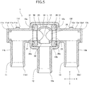
- FIG. 5 is a cross-sectional view taken along line A-A in FIG. 4 .
- FIG. 6 is a left side view of the structure of a modification to the flow channel switching valve in FIG. 1 .
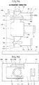
- FIGs. 7 illustrate a method for assembling the flow channel switching valve in FIG. 1 .
- FIGs. 7 show a state in which a molded body that has an integrated valve body and flow channels supported by a jig.
- FIG. 7A is a side view.
- FIG. 7B is a top view.
- the terms "upper, lower, left, and right" are used to represent relative positional relationships of components in the figures and do not represent absolute positional relationships.
- an X-axis direction represents a left-and-right direction
- a Y-axis direction represents a front-and-rear direction (a front-back direction)
- a Z-axis direction represents an up-and-down direction.
- An X-axis, a Y-axis, a Z-axis are perpendicular to each other.
- a flow channel switching valve 1 includes a valve body 10, a first flow channel 11, a second flow channel 12, and a third flow channel 13 that have a circular tube shape, a ball valve member 20 that serves as a valve member, seat members 30, sealing members 31, and a valve shaft 40.
- the flow channel switching valve 1 also includes a case 50, a driving section 60, and a rotational position detection portion 80.
- the valve body 10 is composed of, for example, synthetic resin such as polyphenylene sulfide (PPS) and has a substantially cubic box shape an upper end of which has an opening.
- synthetic resin such as polyphenylene sulfide (PPS)
- the first flow channel 11 that has a substantially L-shape is formed on a left side wall portion 10a of the valve body 10.
- the second flow channel 12 that is linear is formed on a front wall portion 10b of the valve body 10.
- the third flow channel 13 that is plane-symmetrical with the first flow channel 11 and that has a substantially L-shape is formed on a right side wall portion 10c of the valve body 10.
- the first flow channel 11, the second flow channel 12, and the third flow channel 13 are in communication with a valve chamber 14 that is formed in the valve body 10. Two flow channels or four or more flow channels in communication with the valve chamber 14 may be formed.
- the first flow channel 11 includes a first portion 11a, a second portion 11b, a lid member 11c, a pair of projecting portions 11d, and a connecting portion 11e.
- the first portion 11a is linear and is connected to the left side wall portion 10a of the valve body 10.
- a tip end 11a1 of the first portion 11a has an opening for extracting the core of a mold.
- the second portion 11b is linear and is connected so as to be perpendicular to (be at a right angle to) an intermediate part of the first portion 11a.
- the second portion 11b serves as a joint to which a hose is connected.
- the first portion 11a and the second portion 11b may connect each other at an angle that is not the right angle.
- the lid member 11c is joined by ultrasonic welding so as to cover the opening of the tip end 11a1 of the first portion 11a.
- the projecting portions 11d have a quadrangular prism shape that linearly extends.
- the pair of the projecting portions 11d extends in an axial direction (the Y-axis direction) of the second portion 11b from the outer circumferential surface of the first portion 11a to the outer circumferential surface of the second portion 11b.
- the pair of the projecting portions 11d extends across the outer circumferential surface of the first portion 11a and the outer circumferential surface of the second portion 11b.
- the connecting portion 11e has an arced quadrangular prism shape and extends in a circumferential direction on the outer circumferential surface of the first portion 11a so as to couple the pair of the projecting portions 11d with each other.
- the pair of the projecting portions 11d and the connecting portion 11e have the same rectangular cross-sectional shape of a rectangle over the entire length in the longitudinal direction.
- the pair of the projecting portions 11d and the connecting portion 11e are integrally formed with the first portion 11a and the second portion 11b. For this reason, parts of the first portion 11a and the second portion 11b on which the pair of the projecting portions 11d and the connecting portion 11e are disposed have a thickness greater than that of the other part.
- the pair of the projecting portions 11d and the connecting portion 11e are connected to each other so as to form a substantially U-shape when viewed in the axial direction (the X-axis direction) of the first portion 11a.
- front end portions protrude toward the tip end of the second portion 11b and are arranged nearer the tip end of the second portion 11b than the first portion 11a when viewed in the axial direction of the first portion 11a. Consequently, the pair of the projecting portions 11d functions as a positioning stopper with which the hose comes into contact when the hose is mounted on the second portion 11b.
- the pair of the projecting portions 11d and the connecting portion 11e include a planar surface portion 11f that faces the valve body 10 direction (in the opposite direction from the tip end 11a1 of the first portion 11a).
- the shapes and widths (sizes in the X-axis direction) of the pair of the projecting portions 11d and the connecting portion 11e are freely determined unless it goes against the purpose of the present invention.
- the pair of the projecting portions 11d may have a triangular prism shape (a cross-sectional shape is a right triangle shape).
- the projecting portions 11d may have a width equal to a distance between the second portion 11b and the tip end 11a1 of the first portion 11a.
- the pair of the projecting portions 11d and the connecting portion 11e have a shape that can be supported by a jig 200 described later.
- the pair of the projecting portions 11d and the connecting portion 11e preferably include the planar surface portion 11f that faces the valve body 10 direction.
- the connecting portion 11e may be omitted as in a flow channel switching valve 1A according to a modification to the present embodiment illustrated in FIG. 6 .
- the third flow channel 13 includes a first portion 13a, a second portion 13b, a lid member 13c, a pair of projecting portions 13d, and a connecting portion 13e as in the first flow channel 11.
- the lid member 13c is joined by ultrasonic welding so as to cover the opening of a tip end 13a1 of the first portion 13a.
- the pair of the projecting portions 13d and the connecting portion 13e include a planar surface portion 13f that faces the valve body 10 direction (in the opposite direction from the tip end 13a1 of the first portion 13a).
- the third flow channel 13 has the same structure as that of the first flow channel 11 except that the third flow channel 13 is plane-symmetrical with the first flow channel 11, and a detailed description is omitted.
- the opening of a tip end 11b1 of the second portion 11b of the first flow channel 11, the opening of a tip end 12a of the second flow channel 12, and the opening of a tip end 13b1 of the second portion 13b of the third flow channel 13 are directed in the same direction (the front direction).
- the ball valve member 20 is composed of, for example, a material such as metal or synthetic resin and has a hollow ball-like shape (a spherical shape).
- the ball valve member 20 is rotatably supported by the seat members 30 and is installed in the valve chamber 14.
- the ball valve member 20 has a first opening 21 that opens in the left-hand direction, a second opening 22 that opens in the front direction, and a third opening 23 that opens in the righthand direction when being located at a rotational position illustrated in FIG. 5 .
- a switching flow channel 25 that has a substantially T-shape in a plan view and that connects the first opening 21, the second opening 22, and the third opening 23 to each other is formed in the ball valve member 20.
- the ball valve member 20 may have only the first opening 21 and the second opening 22, and the switching flow channel 25 may have a substantially L-shape in a plan view and may connect the first opening 21 and the second opening 22 to each other when being located at the rotational position illustrated in FIG. 5 .
- the ball valve member 20 is used as the valve member, but a columnar valve member may be used.
- the switching flow channel 25 is formed such that connections among the first flow channel 11, the second flow channel 12, and the third flow channel 13 are switched depending on the rotational position of the ball valve member 20. Specifically, the switching flow channel 25 connects the first flow channel 11, the second flow channel 12, and the third flow channel 13 to each other when the ball valve member 20 is located at the rotational position illustrated in FIG. 5 . The switching flow channel 25 connects the first flow channel 11 and the second flow channel 12 to each other when the ball valve member 20 is located at the rotational position at which the ball valve member 20 is rotated 90 degrees clockwise in a plan view from the rotational position illustrated in FIG. 5 .
- the switching flow channel 25 connects the second flow channel 12 and the third flow channel 13 to each other when the ball valve member 20 is located at the rotational position at which the ball valve member 20 is rotated 90 degrees counterclockwise in a plan view from the rotational position illustrated in FIG. 5 .
- a valve shaft insertion hole 24 in which the valve shaft 40 described later is inserted is formed in an upper portion of the ball valve member 20.
- the valve shaft insertion hole 24 is formed such that the ball valve member 20 is rotated about an axis L corresponding to a rotation axis together with rotation of the valve shaft 40 with the valve shaft 40 inserted therein.
- the valve shaft insertion hole 24 has a regular hexagonal shape.
- the seat members 30 are composed of, for example, synthetic resin such as polytetrafluoroethylene (PTFE) and have an annular shape.
- the seat members 30 are paired with each other and are installed in the valve chamber 14 so as to face each other in an interval in the left-and-right direction.
- the seat members 30 interpose and rotatably support the ball valve member 20 in the valve chamber 14.
- the sealing members 31 are, for example, O-rings composed of an elastic material such as a rubber material, one of which is interposed between one of the seat members 30 and the left side wall portion 10a of the valve body 10 so as to be in a compressed state, and the other of which is interposed between the other seat member 30 and the right side wall portion 10c of the valve body 10 so as to be in the compressed state.
- the sealing members 31 are fitted in annular grooves 30a that the seat members 30 have and partly project from the annular grooves 30a.
- the sealing members 31 seal a space between the valve body 10 and the ball valve member 20 together with the seat members 30.
- the valve device may have a structure to omit the sealing members 31 and instead employ seat members 30 that are composed of an elastic material such as a rubber material and that have the function of the sealing members.
- the valve shaft 40 is composed of synthetic resin, has a columnar shape that linearly extends overall, and includes a round columnar portion 41 and a prism portion 42 that is coaxially connected to the lower end of the round columnar portion 41.
- the valve shaft 40 extends along the axis L.
- a groove is formed on a lower end portion of the round columnar portion 41 over the entire circumference, and an O-ring 44 that is composed of, for example, a rubber material and that has an annular shape is fitted in the groove.
- a large-diameter gear 67 of the driving section 60 is coaxially mounted on an upper end portion of the round columnar portion 41.
- a mounting hole 45 that has a substantially round columnar shape along the axis L is formed at the center of an end surface 41a of the round columnar portion 41 that faces upward.
- a potentiometer shaft 81 of the rotational position detection portion 80 is mounted in the mounting hole 45 by press-fitting.
- the prism portion 42 has a columnar shape a cross-sectional shape (a transverse cross-sectional shape) perpendicular to the axis L of which is a regular hexagonal shape as in the valve shaft insertion hole 24.
- the prism portion 42 is inserted in the valve shaft insertion hole 24 of the ball valve member 20 and is consequently mounted on the ball valve member 20 along the axis L.
- the transverse cross-sectional shape of the prism portion 42 is a regular hexagonal shape as in the valve shaft insertion hole 24. For this reason, the valve shaft insertion hole 24 and the prism portion 42 fit together, and the ball valve member 20 is rotated about the axis L together with rotation of the valve shaft 40.
- the prism portion 42 may have a polygonal columnar shape such as a triangular prism shape or a quadrangular prism shape, or a columnar having a D-shaped cross-section having a plane on a part of the circumferential surface, in addition to a regular hexagonal shape.
- the valve shaft insertion hole 24 has the same shape as the transverse cross-sectional shape of the prism portion 42.
- the case 50 is composed of, for example, synthetic resin such as polyphenylene sulfide (PPS) and is mounted on the valve body 10.
- the driving section 60 is installed in the case 50.
- the case 50 includes a motor case portion 51 and a gear case portion 52.
- the motor case portion 51 has a bottomed cylindrical shape, and a motor 61 of the driving section 60 is installed therein.
- the gear case portion 52 includes a bottom wall portion 53 that is integrally formed with the motor case portion 51 and that has a flat plate shape, an upper wall portion 54 in which a ventilation portion 70 is disposed, and a peripheral wall portion 55 that couples the bottom wall portion 53 and the upper wall portion 54 with each other.
- the bottom wall portion 53 and the peripheral wall portion 55 are integrally formed with each other, and the upper wall portion 54 is mounted on the upper end of the peripheral wall portion 55 by using, for example, a screw structure or a snap-fit structure not illustrated.
- a first worm 62, an intermediate gear body 63, and the large-diameter gear 67 of the driving section 60 and the rotational position detection portion 80 are installed in the gear case portion 52.
- the gear case portion 52 includes a cylindrical bearing portion 56 that is integrated with the bottom wall portion 53.
- the round columnar portion 41 of the valve shaft 40 is inserted in the bearing portion 56, and the bearing portion 56 rotatably supports the round columnar portion 41.
- the gear case portion 52 includes an inner peripheral wall portion 57 that protrudes downward from the bottom wall portion 53 and that has a substantially square tube shape.
- the inner peripheral wall portion 57 is inserted in the valve body 10 and is joined to the valve body 10 by, for example, ultrasonic welding.
- the gear case portion 52 may be mounted on the valve body 10 by using, for example, a screw structure.
- the driving section 60 drives and rotates the ball valve member 20 by using the valve shaft 40.
- the driving section 60 includes the motor 61, the first worm 62 that is included in a speed reducer, the intermediate gear body 63, and the large-diameter gear 67.
- the motor 61 is disposed in the motor case portion 51 such that a driving shaft 61a protrudes from a through-hole that is formed in the bottom wall portion 53 of the gear case portion 52 to the space in the gear case portion 52.
- the first worm 62 is mounted on the tip end of the driving shaft 61a.
- the intermediate gear body 63 is disposed in the gear case portion 52.
- the intermediate gear body 63 includes a shaft portion 64, a small-diameter gear 65 (a first worm wheel) that is disposed on one end portion 64a of the shaft portion 64 and that engages with the first worm 62, and a second worm 66 that is disposed on the other end portion 64b of the shaft portion 64 and that engages with the large-diameter gear 67 (a second worm wheel).
- the large-diameter gear 67 is disposed in the gear case portion 52.
- the round columnar portion 41 of the valve shaft 40 is mounted in a through-hole that is formed at the center of the large-diameter gear 67 by press-fitting.
- the driving section 60 transmits rotational force of the driving shaft 61a of the motor 61 to the valve shaft 40 via the first worm 62, the intermediate gear body 63, and the large-diameter gear 67 and causes the valve shaft 40 to rotate about the axis L. Consequently, the ball valve member 20 moves to the desired rotational position.
- the rotational position detection portion 80 includes the potentiometer shaft 81 corresponding to a rotation angle output shaft, a potentiometer base 82 corresponding to a base body, and a potentiometer 85 corresponding to a rotation angle sensor.
- the potentiometer shaft 81 is composed of, for example, metal such as stainless steel or brass, or synthetic resin such as polyphenylene sulfide (PPS) and is formed separately from the valve shaft 40.
- the potentiometer shaft 81 is press-fitted in the mounting hole 45 of the valve shaft 40 and is coaxially secured to and mounted on the valve shaft 40.
- a fitting shaft portion 81a that is disposed on an upper end portion and that has a D-shape engages with a rotor 86 of the potentiometer 85.
- the fitting shaft portion 81a may be integrally formed with the end surface 41a of the valve shaft 40.
- the potentiometer base 82 is composed of synthetic resin and integrally includes a base main body portion 83 and a sensor support portion 84.
- the base main body portion 83 has a substantially flat plate shape and is secured to a boss, not illustrated, that protrudes upward from the bottom wall portion 53 of the gear case portion 52 by using screws 95.
- the sensor support portion 84 has a substantially disk shape the diameter of which is smaller than that of the large-diameter gear 67, and the potentiometer 85 is mounted at the center.
- the sensor support portion 84 is disposed in the gear case portion 52 so as to overlap the large-diameter gear 67 from above.
- the potentiometer 85 is the rotation angle sensor for detecting a rotation angle.
- the potentiometer 85 includes the rotor 86 that has a disk shape and a meter main body portion 87 corresponding to a signal output portion that rotatably supports the rotor 86 and that outputs a signal (voltage) depending on the rotation angle of the rotor 86.
- a fitting hole that has a D-shape in a plan view is formed at the center of the rotor 86.
- the fitting shaft portion 81a of the potentiometer shaft 81 is fitted in the fitting hole such that the fitting shaft portion 81a extends therethrough and such that the rotor 86 is rotated together with the fitting shaft portion 81a.
- the rotor 86 is rotated together with rotation of the fitting shaft portion 81a. Consequently, the potentiometer 85 detects the rotation angle of the potentiometer shaft 81 (that is, the valve shaft 40 and the ball valve member 20) about the axis L.
- the rotational force of the driving shaft 61a of the motor 61 that is included in the driving section 60 is transmitted to the valve shaft 40 via, for example, the large-diameter gear 67, and the valve shaft 40 is rotated about the axis L.
- the ball valve member 20 is rotated about the axis L together with rotation of the valve shaft 40 and moves to the rotational position. This achieves connections of the flow channels depending on the rotational position.
- the potentiometer shaft 81 is rotated about the axis L together with the valve shaft 40, and a signal depending on the rotation angle of the potentiometer shaft 81 is outputted from the potentiometer 85.
- the rotational position of the ball valve member 20 can be monitored based on the signal that is outputted from the potentiometer 85.
- a molded body 5 that includes the valve body 10, the first flow channel 11 (except for the lid member 11c), the second flow channel 12, and the third flow channel 13 (except for the lid member 13c) that are integrated with each other is first obtained by injection molding.
- the molded body 5 is mounted on the jig 200.
- the jig 200 includes a foundation 201 that has a rectangular flat plate shape, a support column 202 that extends upward from the foundation 201, and a support plate 203 that has a flat plate shape and that is mounted on the support column 202 such that an upper surface 203a is horizontal.
- the support plate 203 has a notch (not illustrated) that is along the shape of the outer circumferential surface of the first portion 11a of the first flow channel 11.
- the support plate 203 has a substantially U-shape when viewed from above.
- the first flow channel 11 is inserted into the notch of the support plate 203 with the tip end 11a1 of the first portion 11a facing upward.
- the planar surface portion 11f of the first flow channel 11 is stacked on the upper surface 203a of the support plate 203.
- a retaining member, not illustrated, is mounted on the support plate 203, and the first flow channel 11 is secured to the jig 200. Consequently, the planar surface portion 11f of the first flow channel 11 of the molded body 5 is supported by the jig 200.
- the lid member 11c is stacked so as to cover the opening of the tip end 11a1 of the first portion 11a, and as schematically illustrated by a thick arrow in FIGs. 7 , an ultrasonic vibration is applied to the lid member 11c from above. Consequently, the lid member 11c is joined to the tip end 11a1 of the first portion 11a by ultrasonic welding.
- the planar surface portion 13f is supported by the jig 200, and the lid member 13c is joined as in the first flow channel 11.
- the ball valve member 20, the seat members 30, and the sealing members 31 are installed in the valve body 10 of the molded body 5 to which the lid members 11c and 13c are joined.
- the valve shaft 40 is mounted on the ball valve member 20, and the case 50 is mount on the valve body 10.
- the driving section 60 and the rotational position detection portion 80 are installed in the case 50, and the flow channel switching valve 1 is completed.
- the first flow channel 11 includes the first portion 11a that is connected to the valve body 10 and that is linear, the second portion 11b that is connected such that the second portion 11b is perpendicular to the first portion 11a and that is linear, the lid member 11c that is joined such that the lid member 11c covers the opening of the tip end 11a1 of the first portion 11a, and the pair of the projecting portions 11d that is disposed such that the projecting portions 11d interpose the first portion 11a therebetween in the radial direction and face each other and that extends from the outer circumferential surface of the first portion 11a to the outer circumferential surface of the second portion 11b.
- the lid member 11c can be welded by ultrasonic welding with the pair of the projecting portions 11d supported. Accordingly, the efficiency of ultrasonic welding can be inhibited from decreasing because the pair of the projecting portions 11d is relatively near the welded portion. Since the pair of the projecting portions 11d extends from the outer circumferential surface of the first portion 11a to the outer circumferential surface of the second portion 11b, the parts on which the projecting portions 11d are disposed have a thickness greater than that of the other part, and the rigidity of the connection between the first portion 11a and the second portion 11b can be increased. Accordingly, the rigidity of the first flow channel 11 can be increased, and the efficiency of ultrasonic welding for the first flow channel 11 can be effectively inhibited from decreasing. Since the pair of the projecting portions 11d includes the planar surface portion 11f that faces the valve body 10 direction, the pair of the projecting portions 11d can be stably supported.
- the connecting portion 11e that extends in the circumferential direction on the outer circumferential surface of the first portion 11a so as to couple the pair of the projecting portions 11d with each other and that has an arc shape is further included. In this way, the rigidity of the connection between the first portion 11a and the second portion 11b can be further increased.
- the pair of the projecting portions 11d protrudes toward the tip end of the second portion 11b and is arranged nearer the tip end of the second portion 11b than the first portion 11a when viewed in the axial direction (the X-axis direction) of the first portion 11a.
- the hose is brought into contact with the end surfaces of the pair of the projecting portions 11d that face the tip end of the second portion 11b, and the projecting portions 11d can function as the positioning stopper for the hose.
- the third flow channel 13 has the same structure as that of the first flow channel 11 and exerts the same effects.
- the flow channel switching valve 1 switches between connections among the first flow channel 11, the second flow channel 12, and the third flow channel 13 by using the ball valve member 20.
- the present invention can be used for different kinds of valve devices unless it goes against the purpose thereof.
- the present invention may be used for a valve device such as an on-off valve in which two tubular flow channels are connected to a valve body, and a valve member that is installed in the valve body connects or blocks the two flow channels.
- 1, 1A ⁇ flow channel switching valve 10 ⁇ valve body, 10a ⁇ left side wall portion, 10b ⁇ front wall portion, 10c ⁇ right side wall portion, 11 ⁇ first flow channel, 11a ⁇ first portion, 11a1 ⁇ tip end, 11b ⁇ second portion, 11b1 ⁇ tip end, 11c ⁇ lid member, 11d ⁇ projecting portion, 11e ⁇ connecting portion, 11f ⁇ planar surface portion, 12 ⁇ second flow channel, 12a ⁇ tip end, 13 ⁇ third flow channel, 13a ⁇ first portion, 13a1 ⁇ tip end, 13b ⁇ second portion, 13b1 ⁇ tip end, 13c ⁇ lid member, 13d ⁇ projecting portion, 13e ⁇ connecting portion, 13f ⁇ planar surface portion, 14 ⁇ valve chamber, 20 ⁇ ball valve member, 21 ⁇ first opening, 22 ⁇ second opening, 23 ⁇ third opening, 24 ⁇ valve shaft insertion hole, 25 ⁇ switching flow channel, 30 ⁇ seat member, 30a ⁇ annular groove, 31
Landscapes
- Engineering & Computer Science (AREA)
- General Engineering & Computer Science (AREA)
- Mechanical Engineering (AREA)
- Valve Housings (AREA)
- Electrically Driven Valve-Operating Means (AREA)
- Multiple-Way Valves (AREA)
Abstract
Description
- The present invention relates to a valve device that includes tubular flow channels and a method for assembling the valve device.
- An example of a flow channel switching valve that is one of existing valve devices is disclosed in
Patent Literature 1. The flow channel switching valve includes a valve body that has a valve chamber, a ball-like valve member that is disposed in the valve chamber, a valve shaft that is coupled with the valve member, and a rotation driving section that includes, for example, a drive gear and a motor that rotationally drives the valve member via the valve shaft. - Patent Literature 1:
JP 2018-115690 A - As for such a flow channel switching valve, the shape of a tubular flow channel connected to a valve body may be changed so as to be suitable for a system into which the flow channel switching valve is incorporated. In
Patent Literature 1, three ports as flow channels that have a circular tube shape are each formed so as to linearly extend from the valve body. However, a flow channel, for example, formed in an L-shape may be used in some cases where a hose that is connected to the flow channel is directed to a certain direction. - The L-shaped flow channel includes a first portion that linearly extends from the valve body and a second portion that serves as a hose joint that is connected perpendicular to the first portion. In the case where the L-shaped flow channel is manufactured by injection molding, a tip end of the first portion has an opening for extracting a core of a mold, and a lid member that covers the opening is joined to the tip end of the first portion.
- The lid member is joined in a manner in which the lid member is stacked on the tip end of the first portion, the first portion or a portion that is further from the lid member than the first portion is supported by a jig, and an ultrasonic vibration is applied to the lid member for welding. During ultrasonic welding, a planar surface (that is, a planar surface that faces in the opposite direction from the tip end of the first portion) that faces in a direction in which the ultrasonic vibration is applied needs to be supported by the jig. However, only the valve body has such a planar surface. Accordingly, the distance between a portion that is supported by the jig and a portion that is welded is long, and there is a possibility that the efficiency of ultrasonic welding decreases. In addition, there is a possibility that a connection between the first portion and the second portion damages and deforms due to force that is applied thereto when the hose is mounted on the second portion.
- In view of this, it is an object of the present invention to provide a valve device that can effectively inhibit the efficiency of ultrasonic welding for a flow channel from decreasing and that can increase the rigidity of the flow channel, and a method for assembling the valve device.
- To achieve the object described above, a valve device according to an aspect of the present invention includes a valve body that has a valve chamber, tubular flow channels that are in communication with the valve chamber and that are connected to the valve body, and a valve member that is installed in the valve chamber and that switches between connections of the flow channels. At least one flow channel of the flow channels includes a first portion that is connected to the valve body and that is linear, a second portion that is connected at an angle to the first portion and that is linear, a lid member that is joined such that the lid member covers an opening of a tip end of the first portion, and a pair of projecting portions that is disposed such that the projecting portions interpose the first portion therebetween in a radial direction and face each other and that extends from an outer circumferential surface of the first portion to an outer circumferential surface of the second portion.
- In the present invention, the pair of projecting portions preferably includes a planar surface portion that faces the valve body direction.
- In the present invention, a connecting portion that extends in a circumferential direction on the outer circumferential surface of the first portion such that the connecting portion couples the pair of projecting portions with each other is preferably further included.
- In the present invention, the pair of projecting portions preferably protrudes toward a tip end of the second portion and is arranged nearer the tip end of the second portion than the first portion when viewed in an axial direction of the first portion.
- To achieve the object described above, a method for assembling a valve device according to another aspect of the present invention is a method for assembling a valve device that includes a valve body that has a valve chamber, tubular flow channels that are in communication with the valve chamber and that are connected to the valve body, and a valve member that is installed in the valve chamber and that switches between connections of the flow channels, at least one flow channel of the flow channels including a first portion that is connected to the valve body and that is linear and a second portion that is connected at an angle to the first portion and that is linear. The method includes supporting a planar surface portion that faces the valve body direction and that is included in a pair of projecting portions that is disposed such that the projecting portions interpose the first portion therebetween in a radial direction and face each other and that extends from an outer circumferential surface of the first portion to an outer circumferential surface of the second portion; and stacking a lid member on an opening of a tip end of the first portion and welding the lid member to the first portion by applying an ultrasonic vibration to the lid member.
- According to the present invention, at least one flow channel of the flow channels includes the first portion that is connected to the valve body and that is linear, the second portion that is connected at an angle to the first portion and that is linear, the lid member that is joined such that the lid member covers the opening of the tip end of the first portion, and the pair of projecting portions that is disposed such that the projecting portions interpose the first portion therebetween in the radial direction and face each other and that extends from the outer circumferential surface of the first portion to the outer circumferential surface of the second portion. In this way, the lid member can be welded by ultrasonic welding with the pair of projecting portions supported. Accordingly, the efficiency of ultrasonic welding can be inhibited from decreasing because the pair of projecting portions is relatively near a welded portion. Since the pair of projecting portions extends from the outer circumferential surface of the first portion to the outer circumferential surface of the second portion, parts on which the projecting portions are disposed have a thickness greater than that of the other part, and the rigidity of a connection between the first portion and the second portion can be increased. Accordingly, the efficiency of ultrasonic welding for the flow channel can be effectively inhibited from decreasing, and the rigidity of the flow channel can be increased. Since the pair of projecting portions includes the planar surface portion that faces the valve body direction, the pair of projecting portions can be stably supported.
- Since the connecting portion that extends in the circumferential direction on the outer circumferential surface of the first portion so as to couple the pair of projecting portions with each other is further included, the rigidity of the connection between the first portion and the second portion can be further increased.
- Since the pair of projecting portions protrudes toward the tip end of the second portion and is arranged nearer the tip end of the second portion than the first portion when viewed in the axial direction of the first portion, the hose is brought into contact with the end surfaces of the pair of projecting portions that face the tip end of the second portion, and the projecting portions can function as a positioning stopper for the hose.
-
- [
FIG. 1] FIG. 1 is a perspective view of a flow channel switching valve according to an embodiment of the present invention. - [
FIG. 2] FIG. 2 is a left side view of the flow channel switching valve inFIG. 1 . - [
FIG. 3] FIG. 3 is a plan view of the flow channel switching valve inFIG. 1 with an upper wall portion of a gear case portion removed. - [
FIG. 4] FIG. 4 is a vertical cross-sectional view of the flow channel switching valve inFIG. 1 . - [
FIG. 5] FIG. 5 is a cross-sectional view taken along line A-A inFIG. 4 . - [
FIG. 6] FIG. 6 is a left side view of the structure of a modification to the flow channel switching valve inFIG. 1 . - [
FIG. 7] FIGs. 7 illustrate a method for assembling the flow channel switching valve inFIG. 1 . - A flow channel switching valve corresponding to a valve device according to an embodiment of the present invention will now be described with reference to
FIG. 1 to FIGs. 7 . -
FIG. 1 is a perspective view of the flow channel switching valve according to the embodiment of the present invention.FIG. 2 is a left side view of the flow channel switching valve inFIG. 1 .FIG. 3 is a plan view of the flow channel switching valve inFIG. 1 with an upper wall portion of a gear case portion removed.FIG. 4 is a cross-sectional view (a vertical cross-sectional view) of the flow channel switching valve inFIG. 1 taken along a rotation axis of a valve member.FIG. 5 is a cross-sectional view taken along line A-A inFIG. 4 .FIG. 6 is a left side view of the structure of a modification to the flow channel switching valve inFIG. 1 .FIGs. 7 illustrate a method for assembling the flow channel switching valve inFIG. 1 .FIGs. 7 show a state in which a molded body that has an integrated valve body and flow channels supported by a jig.FIG. 7A is a side view.FIG. 7B is a top view. In the following description, the terms "upper, lower, left, and right" are used to represent relative positional relationships of components in the figures and do not represent absolute positional relationships. InFIG. 1 to FIG. 6 , an X-axis direction represents a left-and-right direction, a Y-axis direction represents a front-and-rear direction (a front-back direction), and a Z-axis direction represents an up-and-down direction. An X-axis, a Y-axis, a Z-axis are perpendicular to each other. - As illustrated in the figures, a flow
channel switching valve 1 according to the present embodiment includes avalve body 10, afirst flow channel 11, asecond flow channel 12, and athird flow channel 13 that have a circular tube shape, aball valve member 20 that serves as a valve member,seat members 30,sealing members 31, and avalve shaft 40. The flowchannel switching valve 1 also includes acase 50, adriving section 60, and a rotationalposition detection portion 80. - The
valve body 10 is composed of, for example, synthetic resin such as polyphenylene sulfide (PPS) and has a substantially cubic box shape an upper end of which has an opening. - The
first flow channel 11 that has a substantially L-shape is formed on a leftside wall portion 10a of thevalve body 10. Thesecond flow channel 12 that is linear is formed on afront wall portion 10b of thevalve body 10. Thethird flow channel 13 that is plane-symmetrical with thefirst flow channel 11 and that has a substantially L-shape is formed on a rightside wall portion 10c of thevalve body 10. Thefirst flow channel 11, thesecond flow channel 12, and thethird flow channel 13 are in communication with avalve chamber 14 that is formed in thevalve body 10. Two flow channels or four or more flow channels in communication with thevalve chamber 14 may be formed. - The
first flow channel 11 includes afirst portion 11a, asecond portion 11b, alid member 11c, a pair of projectingportions 11d, and a connectingportion 11e. Thefirst portion 11a is linear and is connected to the leftside wall portion 10a of thevalve body 10. A tip end 11a1 of thefirst portion 11a has an opening for extracting the core of a mold. Thesecond portion 11b is linear and is connected so as to be perpendicular to (be at a right angle to) an intermediate part of thefirst portion 11a. Thesecond portion 11b serves as a joint to which a hose is connected. Thefirst portion 11a and thesecond portion 11b may connect each other at an angle that is not the right angle. Thelid member 11c is joined by ultrasonic welding so as to cover the opening of the tip end 11a1 of thefirst portion 11a. - The projecting
portions 11d have a quadrangular prism shape that linearly extends. The pair of the projectingportions 11d extends in an axial direction (the Y-axis direction) of thesecond portion 11b from the outer circumferential surface of thefirst portion 11a to the outer circumferential surface of thesecond portion 11b. In other words, the pair of the projectingportions 11d extends across the outer circumferential surface of thefirst portion 11a and the outer circumferential surface of thesecond portion 11b. The connectingportion 11e has an arced quadrangular prism shape and extends in a circumferential direction on the outer circumferential surface of thefirst portion 11a so as to couple the pair of the projectingportions 11d with each other. The pair of the projectingportions 11d and the connectingportion 11e have the same rectangular cross-sectional shape of a rectangle over the entire length in the longitudinal direction. The pair of the projectingportions 11d and the connectingportion 11e are integrally formed with thefirst portion 11a and thesecond portion 11b. For this reason, parts of thefirst portion 11a and thesecond portion 11b on which the pair of the projectingportions 11d and the connectingportion 11e are disposed have a thickness greater than that of the other part. The pair of the projectingportions 11d and the connectingportion 11e are connected to each other so as to form a substantially U-shape when viewed in the axial direction (the X-axis direction) of thefirst portion 11a. As for the pair of the projectingportions 11d, front end portions (end portions opposite the connectingportion 11e) protrude toward the tip end of thesecond portion 11b and are arranged nearer the tip end of thesecond portion 11b than thefirst portion 11a when viewed in the axial direction of thefirst portion 11a. Consequently, the pair of the projectingportions 11d functions as a positioning stopper with which the hose comes into contact when the hose is mounted on thesecond portion 11b. - The pair of the projecting
portions 11d and the connectingportion 11e include aplanar surface portion 11f that faces thevalve body 10 direction (in the opposite direction from the tip end 11a1 of thefirst portion 11a). The shapes and widths (sizes in the X-axis direction) of the pair of the projectingportions 11d and the connectingportion 11e are freely determined unless it goes against the purpose of the present invention. For example, the pair of the projectingportions 11d may have a triangular prism shape (a cross-sectional shape is a right triangle shape). The projectingportions 11d may have a width equal to a distance between thesecond portion 11b and the tip end 11a1 of thefirst portion 11a. The pair of the projectingportions 11d and the connectingportion 11e have a shape that can be supported by ajig 200 described later. The pair of the projectingportions 11d and the connectingportion 11e preferably include theplanar surface portion 11f that faces thevalve body 10 direction. As for the flowchannel switching valve 1, the connectingportion 11e may be omitted as in a flowchannel switching valve 1A according to a modification to the present embodiment illustrated inFIG. 6 . - The
third flow channel 13 includes afirst portion 13a, asecond portion 13b, alid member 13c, a pair of projectingportions 13d, and a connectingportion 13e as in thefirst flow channel 11. Thelid member 13c is joined by ultrasonic welding so as to cover the opening of a tip end 13a1 of thefirst portion 13a. The pair of the projectingportions 13d and the connectingportion 13e include aplanar surface portion 13f that faces thevalve body 10 direction (in the opposite direction from the tip end 13a1 of thefirst portion 13a). Thethird flow channel 13 has the same structure as that of thefirst flow channel 11 except that thethird flow channel 13 is plane-symmetrical with thefirst flow channel 11, and a detailed description is omitted. - In the present embodiment, the opening of a tip end 11b1 of the
second portion 11b of thefirst flow channel 11, the opening of atip end 12a of thesecond flow channel 12, and the opening of a tip end 13b1 of thesecond portion 13b of thethird flow channel 13 are directed in the same direction (the front direction). - The
ball valve member 20 is composed of, for example, a material such as metal or synthetic resin and has a hollow ball-like shape (a spherical shape). Theball valve member 20 is rotatably supported by theseat members 30 and is installed in thevalve chamber 14. Theball valve member 20 has afirst opening 21 that opens in the left-hand direction, asecond opening 22 that opens in the front direction, and athird opening 23 that opens in the righthand direction when being located at a rotational position illustrated inFIG. 5 . A switchingflow channel 25 that has a substantially T-shape in a plan view and that connects thefirst opening 21, thesecond opening 22, and thethird opening 23 to each other is formed in theball valve member 20. For example, theball valve member 20 may have only thefirst opening 21 and thesecond opening 22, and theswitching flow channel 25 may have a substantially L-shape in a plan view and may connect thefirst opening 21 and thesecond opening 22 to each other when being located at the rotational position illustrated inFIG. 5 . In the present embodiment, theball valve member 20 is used as the valve member, but a columnar valve member may be used. - The switching
flow channel 25 is formed such that connections among thefirst flow channel 11, thesecond flow channel 12, and thethird flow channel 13 are switched depending on the rotational position of theball valve member 20. Specifically, the switchingflow channel 25 connects thefirst flow channel 11, thesecond flow channel 12, and thethird flow channel 13 to each other when theball valve member 20 is located at the rotational position illustrated inFIG. 5 . The switchingflow channel 25 connects thefirst flow channel 11 and thesecond flow channel 12 to each other when theball valve member 20 is located at the rotational position at which theball valve member 20 is rotated 90 degrees clockwise in a plan view from the rotational position illustrated inFIG. 5 . The switchingflow channel 25 connects thesecond flow channel 12 and thethird flow channel 13 to each other when theball valve member 20 is located at the rotational position at which theball valve member 20 is rotated 90 degrees counterclockwise in a plan view from the rotational position illustrated inFIG. 5 . - A valve
shaft insertion hole 24 in which thevalve shaft 40 described later is inserted is formed in an upper portion of theball valve member 20. The valveshaft insertion hole 24 is formed such that theball valve member 20 is rotated about an axis L corresponding to a rotation axis together with rotation of thevalve shaft 40 with thevalve shaft 40 inserted therein. In the present embodiment, the valveshaft insertion hole 24 has a regular hexagonal shape. - The
seat members 30 are composed of, for example, synthetic resin such as polytetrafluoroethylene (PTFE) and have an annular shape. Theseat members 30 are paired with each other and are installed in thevalve chamber 14 so as to face each other in an interval in the left-and-right direction. Theseat members 30 interpose and rotatably support theball valve member 20 in thevalve chamber 14. - The sealing
members 31 are, for example, O-rings composed of an elastic material such as a rubber material, one of which is interposed between one of theseat members 30 and the leftside wall portion 10a of thevalve body 10 so as to be in a compressed state, and the other of which is interposed between theother seat member 30 and the rightside wall portion 10c of thevalve body 10 so as to be in the compressed state. In the present embodiment, the sealingmembers 31 are fitted inannular grooves 30a that theseat members 30 have and partly project from theannular grooves 30a. The sealingmembers 31 seal a space between thevalve body 10 and theball valve member 20 together with theseat members 30. The valve device may have a structure to omit the sealingmembers 31 and instead employseat members 30 that are composed of an elastic material such as a rubber material and that have the function of the sealing members. - The
valve shaft 40 is composed of synthetic resin, has a columnar shape that linearly extends overall, and includes around columnar portion 41 and aprism portion 42 that is coaxially connected to the lower end of theround columnar portion 41. Thevalve shaft 40 extends along the axis L. - A groove is formed on a lower end portion of the
round columnar portion 41 over the entire circumference, and an O-ring 44 that is composed of, for example, a rubber material and that has an annular shape is fitted in the groove. A large-diameter gear 67 of the drivingsection 60 is coaxially mounted on an upper end portion of theround columnar portion 41. A mountinghole 45 that has a substantially round columnar shape along the axis L is formed at the center of anend surface 41a of theround columnar portion 41 that faces upward. Apotentiometer shaft 81 of the rotationalposition detection portion 80 is mounted in the mountinghole 45 by press-fitting. - The
prism portion 42 has a columnar shape a cross-sectional shape (a transverse cross-sectional shape) perpendicular to the axis L of which is a regular hexagonal shape as in the valveshaft insertion hole 24. Theprism portion 42 is inserted in the valveshaft insertion hole 24 of theball valve member 20 and is consequently mounted on theball valve member 20 along the axis L. The transverse cross-sectional shape of theprism portion 42 is a regular hexagonal shape as in the valveshaft insertion hole 24. For this reason, the valveshaft insertion hole 24 and theprism portion 42 fit together, and theball valve member 20 is rotated about the axis L together with rotation of thevalve shaft 40. Theprism portion 42 may have a polygonal columnar shape such as a triangular prism shape or a quadrangular prism shape, or a columnar having a D-shaped cross-section having a plane on a part of the circumferential surface, in addition to a regular hexagonal shape. In this case, the valveshaft insertion hole 24 has the same shape as the transverse cross-sectional shape of theprism portion 42. - The
case 50 is composed of, for example, synthetic resin such as polyphenylene sulfide (PPS) and is mounted on thevalve body 10. The drivingsection 60 is installed in thecase 50. Thecase 50 includes amotor case portion 51 and agear case portion 52. - The
motor case portion 51 has a bottomed cylindrical shape, and amotor 61 of the drivingsection 60 is installed therein. - The
gear case portion 52 includes abottom wall portion 53 that is integrally formed with themotor case portion 51 and that has a flat plate shape, anupper wall portion 54 in which aventilation portion 70 is disposed, and aperipheral wall portion 55 that couples thebottom wall portion 53 and theupper wall portion 54 with each other. In the present embodiment, thebottom wall portion 53 and theperipheral wall portion 55 are integrally formed with each other, and theupper wall portion 54 is mounted on the upper end of theperipheral wall portion 55 by using, for example, a screw structure or a snap-fit structure not illustrated. Afirst worm 62, anintermediate gear body 63, and the large-diameter gear 67 of the drivingsection 60 and the rotationalposition detection portion 80 are installed in thegear case portion 52. - The
gear case portion 52 includes acylindrical bearing portion 56 that is integrated with thebottom wall portion 53. Theround columnar portion 41 of thevalve shaft 40 is inserted in the bearingportion 56, and the bearingportion 56 rotatably supports theround columnar portion 41. Thegear case portion 52 includes an innerperipheral wall portion 57 that protrudes downward from thebottom wall portion 53 and that has a substantially square tube shape. The innerperipheral wall portion 57 is inserted in thevalve body 10 and is joined to thevalve body 10 by, for example, ultrasonic welding. Thegear case portion 52 may be mounted on thevalve body 10 by using, for example, a screw structure. - The driving
section 60 drives and rotates theball valve member 20 by using thevalve shaft 40. The drivingsection 60 includes themotor 61, thefirst worm 62 that is included in a speed reducer, theintermediate gear body 63, and the large-diameter gear 67. - The
motor 61 is disposed in themotor case portion 51 such that a drivingshaft 61a protrudes from a through-hole that is formed in thebottom wall portion 53 of thegear case portion 52 to the space in thegear case portion 52. Thefirst worm 62 is mounted on the tip end of the drivingshaft 61a. - The
intermediate gear body 63 is disposed in thegear case portion 52. Theintermediate gear body 63 includes ashaft portion 64, a small-diameter gear 65 (a first worm wheel) that is disposed on oneend portion 64a of theshaft portion 64 and that engages with thefirst worm 62, and asecond worm 66 that is disposed on theother end portion 64b of theshaft portion 64 and that engages with the large-diameter gear 67 (a second worm wheel). - The large-
diameter gear 67 is disposed in thegear case portion 52. Theround columnar portion 41 of thevalve shaft 40 is mounted in a through-hole that is formed at the center of the large-diameter gear 67 by press-fitting. - The driving
section 60 transmits rotational force of the drivingshaft 61a of themotor 61 to thevalve shaft 40 via thefirst worm 62, theintermediate gear body 63, and the large-diameter gear 67 and causes thevalve shaft 40 to rotate about the axis L. Consequently, theball valve member 20 moves to the desired rotational position. - The rotational
position detection portion 80 includes thepotentiometer shaft 81 corresponding to a rotation angle output shaft, apotentiometer base 82 corresponding to a base body, and apotentiometer 85 corresponding to a rotation angle sensor. - The
potentiometer shaft 81 is composed of, for example, metal such as stainless steel or brass, or synthetic resin such as polyphenylene sulfide (PPS) and is formed separately from thevalve shaft 40. Thepotentiometer shaft 81 is press-fitted in the mountinghole 45 of thevalve shaft 40 and is coaxially secured to and mounted on thevalve shaft 40. As for thepotentiometer shaft 81, afitting shaft portion 81a that is disposed on an upper end portion and that has a D-shape engages with arotor 86 of thepotentiometer 85. Thefitting shaft portion 81a may be integrally formed with theend surface 41a of thevalve shaft 40. - The
potentiometer base 82 is composed of synthetic resin and integrally includes a basemain body portion 83 and asensor support portion 84. The basemain body portion 83 has a substantially flat plate shape and is secured to a boss, not illustrated, that protrudes upward from thebottom wall portion 53 of thegear case portion 52 by usingscrews 95. Thesensor support portion 84 has a substantially disk shape the diameter of which is smaller than that of the large-diameter gear 67, and thepotentiometer 85 is mounted at the center. Thesensor support portion 84 is disposed in thegear case portion 52 so as to overlap the large-diameter gear 67 from above. - The
potentiometer 85 is the rotation angle sensor for detecting a rotation angle. Thepotentiometer 85 includes therotor 86 that has a disk shape and a metermain body portion 87 corresponding to a signal output portion that rotatably supports therotor 86 and that outputs a signal (voltage) depending on the rotation angle of therotor 86. A fitting hole that has a D-shape in a plan view is formed at the center of therotor 86. Thefitting shaft portion 81a of thepotentiometer shaft 81 is fitted in the fitting hole such that thefitting shaft portion 81a extends therethrough and such that therotor 86 is rotated together with thefitting shaft portion 81a. Therotor 86 is rotated together with rotation of thefitting shaft portion 81a. Consequently, thepotentiometer 85 detects the rotation angle of the potentiometer shaft 81 (that is, thevalve shaft 40 and the ball valve member 20) about the axis L. - As for the flow
channel switching valve 1, the rotational force of the drivingshaft 61a of themotor 61 that is included in thedriving section 60 is transmitted to thevalve shaft 40 via, for example, the large-diameter gear 67, and thevalve shaft 40 is rotated about the axis L. Theball valve member 20 is rotated about the axis L together with rotation of thevalve shaft 40 and moves to the rotational position. This achieves connections of the flow channels depending on the rotational position. Thepotentiometer shaft 81 is rotated about the axis L together with thevalve shaft 40, and a signal depending on the rotation angle of thepotentiometer shaft 81 is outputted from thepotentiometer 85. The rotational position of theball valve member 20 can be monitored based on the signal that is outputted from thepotentiometer 85. - A method for assembling the flow
channel switching valve 1 according to the present embodiment described above will now be described with reference toFIGs. 7 . - A molded
body 5 that includes thevalve body 10, the first flow channel 11 (except for thelid member 11c), thesecond flow channel 12, and the third flow channel 13 (except for thelid member 13c) that are integrated with each other is first obtained by injection molding. - Subsequently, the molded
body 5 is mounted on thejig 200. As illustrated inFIGs. 7 , thejig 200 includes afoundation 201 that has a rectangular flat plate shape, asupport column 202 that extends upward from thefoundation 201, and asupport plate 203 that has a flat plate shape and that is mounted on thesupport column 202 such that anupper surface 203a is horizontal. Thesupport plate 203 has a notch (not illustrated) that is along the shape of the outer circumferential surface of thefirst portion 11a of thefirst flow channel 11. Thesupport plate 203 has a substantially U-shape when viewed from above. Thefirst flow channel 11 is inserted into the notch of thesupport plate 203 with the tip end 11a1 of thefirst portion 11a facing upward. Theplanar surface portion 11f of thefirst flow channel 11 is stacked on theupper surface 203a of thesupport plate 203. A retaining member, not illustrated, is mounted on thesupport plate 203, and thefirst flow channel 11 is secured to thejig 200. Consequently, theplanar surface portion 11f of thefirst flow channel 11 of the moldedbody 5 is supported by thejig 200. - Subsequently, the
lid member 11c is stacked so as to cover the opening of the tip end 11a1 of thefirst portion 11a, and as schematically illustrated by a thick arrow inFIGs. 7 , an ultrasonic vibration is applied to thelid member 11c from above. Consequently, thelid member 11c is joined to the tip end 11a1 of thefirst portion 11a by ultrasonic welding. As for thethird flow channel 13, theplanar surface portion 13f is supported by thejig 200, and thelid member 13c is joined as in thefirst flow channel 11. - The
ball valve member 20, theseat members 30, and the sealingmembers 31 are installed in thevalve body 10 of the moldedbody 5 to which thelid members valve shaft 40 is mounted on theball valve member 20, and thecase 50 is mount on thevalve body 10. The drivingsection 60 and the rotationalposition detection portion 80 are installed in thecase 50, and the flowchannel switching valve 1 is completed. - As for the flow
channel switching valve 1 according to the present embodiment described above, thefirst flow channel 11 includes thefirst portion 11a that is connected to thevalve body 10 and that is linear, thesecond portion 11b that is connected such that thesecond portion 11b is perpendicular to thefirst portion 11a and that is linear, thelid member 11c that is joined such that thelid member 11c covers the opening of the tip end 11a1 of thefirst portion 11a, and the pair of the projectingportions 11d that is disposed such that the projectingportions 11d interpose thefirst portion 11a therebetween in the radial direction and face each other and that extends from the outer circumferential surface of thefirst portion 11a to the outer circumferential surface of thesecond portion 11b. In this way, thelid member 11c can be welded by ultrasonic welding with the pair of the projectingportions 11d supported. Accordingly, the efficiency of ultrasonic welding can be inhibited from decreasing because the pair of the projectingportions 11d is relatively near the welded portion. Since the pair of the projectingportions 11d extends from the outer circumferential surface of thefirst portion 11a to the outer circumferential surface of thesecond portion 11b, the parts on which the projectingportions 11d are disposed have a thickness greater than that of the other part, and the rigidity of the connection between thefirst portion 11a and thesecond portion 11b can be increased. Accordingly, the rigidity of thefirst flow channel 11 can be increased, and the efficiency of ultrasonic welding for thefirst flow channel 11 can be effectively inhibited from decreasing. Since the pair of the projectingportions 11d includes theplanar surface portion 11f that faces thevalve body 10 direction, the pair of the projectingportions 11d can be stably supported. - The connecting
portion 11e that extends in the circumferential direction on the outer circumferential surface of thefirst portion 11a so as to couple the pair of the projectingportions 11d with each other and that has an arc shape is further included. In this way, the rigidity of the connection between thefirst portion 11a and thesecond portion 11b can be further increased. - The pair of the projecting
portions 11d protrudes toward the tip end of thesecond portion 11b and is arranged nearer the tip end of thesecond portion 11b than thefirst portion 11a when viewed in the axial direction (the X-axis direction) of thefirst portion 11a. In this way, the hose is brought into contact with the end surfaces of the pair of the projectingportions 11d that face the tip end of thesecond portion 11b, and the projectingportions 11d can function as the positioning stopper for the hose. - The
third flow channel 13 has the same structure as that of thefirst flow channel 11 and exerts the same effects. - The flow
channel switching valve 1 according to the embodiment described above switches between connections among thefirst flow channel 11, thesecond flow channel 12, and thethird flow channel 13 by using theball valve member 20. The present invention, however, can be used for different kinds of valve devices unless it goes against the purpose thereof. For example, the present invention may be used for a valve device such as an on-off valve in which two tubular flow channels are connected to a valve body, and a valve member that is installed in the valve body connects or blocks the two flow channels. - The embodiment of the present invention is described above. The present invention, however, is not limited to the embodiment. Embodiments obtained by appropriately adding, removing, or modifying components according to the embodiment described above by a person skilled in the art, and an embodiment obtained by appropriately combining features of the embodiment are included in the scope of the present invention without departing from the spirit of the present invention.
- 1, 1A ··· flow channel switching valve, 10 ··· valve body, 10a ··· left side wall portion, 10b ··· front wall portion, 10c ··· right side wall portion, 11 ··· first flow channel, 11a ··· first portion, 11a1 ··· tip end, 11b ··· second portion, 11b1 ··· tip end, 11c ··· lid member, 11d ··· projecting portion, 11e ··· connecting portion, 11f ··· planar surface portion, 12 ··· second flow channel, 12a ··· tip end, 13 ··· third flow channel, 13a ··· first portion, 13a1 ··· tip end, 13b ··· second portion, 13b1 ··· tip end, 13c ··· lid member, 13d ··· projecting portion, 13e ··· connecting portion, 13f ··· planar surface portion, 14 ··· valve chamber, 20 ··· ball valve member, 21 ··· first opening, 22 ··· second opening, 23 ··· third opening, 24 ··· valve shaft insertion hole, 25 ··· switching flow channel, 30 ··· seat member, 30a ··· annular groove, 31 ··· sealing member, 40 ··· valve shaft, 41 ··· round columnar portion, 41a ··· end surface, 42 ··· prism portion, 44 ··· O-ring, 45 ··· mounting hole, 50 ··· case, 51 ··· motor case portion, 52 ··· gear case portion, 53 ··· bottom wall portion, 54 ··· upper wall portion, 55 ··· peripheral wall portion, 56 ··· bearing portion, 57 ··· inner peripheral wall portion, 60 ··· driving section, 61 ··· motor, 61a ··· driving shaft, 62 ··· first worm, 63 ··· intermediate gear body, 64 ··· shaft portion, 64a ··· one end portion, 64b ··· the other end portion, 65 ··· small-diameter gear, 66 ··· second worm, 67 ··· large-diameter gear, 70 ··· ventilation portion, 80 ··· rotational position detection portion, 81 ··· potentiometer shaft, 81a ··· fitting shaft portion, 82 ··· potentiometer base, 83 ··· base main body portion, 84 ··· sensor support portion, 85 ··· potentiometer, 86 ··· rotor, 87 ··· meter main body portion, 95 ··· screw
Claims (5)
- A valve device comprising: a valve body that has a valve chamber; tubular flow channels that are in communication with the valve chamber and that are connected to the valve body; and a valve member that is installed in the valve chamber and that switches between connections of the flow channels,
wherein at least one flow channel of the flow channels includes a first portion that is connected to the valve body and that is linear, a second portion that is connected at an angle to the first portion and that is linear, a lid member that is joined such that the lid member covers an opening of a tip end of the first portion, and a pair of projecting portions that is disposed such that the projecting portions interpose the first portion therebetween in a radial direction and face each other and that extends from an outer circumferential surface of the first portion to an outer circumferential surface of the second portion. - The valve device according to Claim 1, wherein the pair of projecting portions includes a planar surface portion that faces the valve body direction.
- The valve device according to Claim 1 or Claim 2, further comprising: a connecting portion that extends in a circumferential direction on the outer circumferential surface of the first portion such that the connecting portion couples the pair of projecting portions with each other.
- The valve device according to any one of Claim 1 to Claim 3, wherein the pair of projecting portions protrudes toward a tip end of the second portion and is arranged nearer the tip end of the second portion than the first portion when viewed in an axial direction of the first portion.
- A method for assembling a valve device that includes a valve body that has a valve chamber, tubular flow channels that are in communication with the valve chamber and that are connected to the valve body, and a valve member that is installed in the valve chamber and that switches between connections of the flow channels, at least one flow channel of the flow channels including a first portion that is connected to the valve body and that is linear and a second portion that is connected at an angle to the first portion and that is linear, the method comprising:supporting a planar surface portion that faces the valve body direction and that is included in a pair of projecting portions that is disposed such that the projecting portions interpose the first portion therebetween in a radial direction and face each other and that extends from an outer circumferential surface of the first portion to an outer circumferential surface of the second portion; andstacking a lid member on an opening of a tip end of the first portion and welding the lid member to the first portion by applying an ultrasonic vibration to the lid member.
Applications Claiming Priority (2)
| Application Number | Priority Date | Filing Date | Title |
|---|---|---|---|
| JP2018210263A JP6999177B2 (en) | 2018-11-08 | 2018-11-08 | Valve device and its assembly method |
| PCT/JP2019/040267 WO2020095624A1 (en) | 2018-11-08 | 2019-10-11 | Valve device and assembly method therefor |
Publications (3)
| Publication Number | Publication Date |
|---|---|
| EP3879151A1 true EP3879151A1 (en) | 2021-09-15 |
| EP3879151A4 EP3879151A4 (en) | 2022-08-10 |
| EP3879151B1 EP3879151B1 (en) | 2025-08-20 |
Family
ID=70612380
Family Applications (1)
| Application Number | Title | Priority Date | Filing Date |
|---|---|---|---|
| EP19881846.0A Active EP3879151B1 (en) | 2018-11-08 | 2019-10-11 | Valve device and assembly method therefor |
Country Status (5)
| Country | Link |
|---|---|
| US (1) | US11448333B2 (en) |
| EP (1) | EP3879151B1 (en) |
| JP (1) | JP6999177B2 (en) |
| CN (1) | CN112930453B (en) |
| WO (1) | WO2020095624A1 (en) |
Families Citing this family (5)
| Publication number | Priority date | Publication date | Assignee | Title |
|---|---|---|---|---|
| CN210770428U (en) * | 2019-06-24 | 2020-06-16 | 盾安环境技术有限公司 | Three-way water valve |
| CN114051602B (en) * | 2020-04-24 | 2024-03-22 | 松下知识产权经营株式会社 | Portable terminal |
| KR102454307B1 (en) * | 2020-12-08 | 2022-10-14 | 유완기 | Faucet connection type directional control valve for easy detachment |
| CN113725521B (en) * | 2021-08-31 | 2024-03-19 | 奇瑞新能源汽车股份有限公司 | Flow control device, battery pack, and cooling control method for battery pack |
| US20230294115A1 (en) * | 2022-03-17 | 2023-09-21 | Shin Tai Spurt Water Of The Garden Tools Co., Ltd | Dual-Outlet Water Adapter for Gardening |
Family Cites Families (41)
| Publication number | Priority date | Publication date | Assignee | Title |
|---|---|---|---|---|
| US461891A (en) * | 1891-10-27 | richardson | ||
| US3633421A (en) * | 1970-04-22 | 1972-01-11 | Dwyer Instr | Molded plastic flowmeter and control valve therefor |
| US4100940A (en) * | 1972-03-09 | 1978-07-18 | Robert Wayne Spears | Trickle emitter for subterranean irrigation |
| DE3151640C2 (en) | 1981-12-28 | 1985-09-05 | Continental Gummi-Werke Ag, 3000 Hannover | Process for the production of a rubber or plastic hose with textile reinforcement inserts with a branch hose attached to the side |
| US4708374A (en) * | 1984-07-30 | 1987-11-24 | Naco Industries, Inc. | Plastic Tee fitting |
| US5474102A (en) * | 1991-07-15 | 1995-12-12 | Lopez; Robert | Fluid distribution manifold |
| FI110139B (en) * | 1999-03-22 | 2002-11-29 | Pexep Oy | Manifold |
| KR100615994B1 (en) * | 1999-06-18 | 2006-08-28 | 파커-한니핀 코포레이션 | In-line selector valve with outlet and capacity |
| US6289913B1 (en) * | 1999-12-22 | 2001-09-18 | Eaton Corporation | Servo motor operated rotary bypass valve |
| FI115485B (en) * | 2001-07-06 | 2005-05-13 | Uponor Innovation Ab | Branching piece in a pipe system |
| JP3944706B2 (en) * | 2002-02-14 | 2007-07-18 | 株式会社ニフコ | 2-way valve |
| US7326188B1 (en) * | 2002-08-02 | 2008-02-05 | Elcam Medical | Anesthesia manifold and induction valve |
| FI115852B (en) * | 2003-03-03 | 2005-07-29 | Uponor Innovation Ab | dISTRIBUTOR |
| JP2005083395A (en) * | 2003-09-04 | 2005-03-31 | Nifco Inc | Pressure opening and shutting valve |
| US6951228B2 (en) * | 2003-12-04 | 2005-10-04 | B Braun Medical Inc. | Bulk compounder manifold |
| US7600530B2 (en) * | 2004-08-09 | 2009-10-13 | Medegen, Inc. | Connector with check valve and method of use |
| US7771383B2 (en) * | 2004-10-22 | 2010-08-10 | Medegen, Inc. | Fluid control device with valve and methods of use |
| WO2006058177A2 (en) * | 2004-11-23 | 2006-06-01 | Vassallo Research & Development Corporation | Reinforced fitting and pipe |
| JP4800071B2 (en) * | 2005-06-02 | 2011-10-26 | 株式会社クレハ | Rotary switching valve, switching valve device, filling packaging body manufacturing apparatus, and filling packaging body manufacturing method |
| JP3914560B1 (en) * | 2006-01-31 | 2007-05-16 | 東京応化工業株式会社 | Fittings for fluid containers |
| MX2009012003A (en) * | 2007-05-11 | 2009-11-19 | Lubrizol Advanced Mat Inc | Water manifold system and method. |
| JP4589955B2 (en) * | 2007-12-19 | 2010-12-01 | 積水化学工業株式会社 | Connection structure between tubular connecting member and joint member |
| US8561638B2 (en) * | 2008-12-02 | 2013-10-22 | Piolax Inc. | Check valve |
| CA2764369C (en) * | 2009-06-02 | 2014-08-12 | Prinsco, Inc. | Rib construction for large diameter pipe fittings |
| US9399149B2 (en) * | 2009-10-23 | 2016-07-26 | Flight Suits | Flexible fitting for heat exchanging garments |
| US20120286506A1 (en) * | 2011-05-10 | 2012-11-15 | Mckenzie Daniel | Water manifold |
| WO2014149566A1 (en) * | 2013-03-15 | 2014-09-25 | Icu Medical , Inc. | Medical connector |
| US9662253B2 (en) * | 2013-03-15 | 2017-05-30 | Kap Medical | Bidirectional fluid flow valve and method |
| KR101384508B1 (en) | 2013-06-07 | 2014-04-14 | 주식회사 한얼인터프론 | Fitting device for connecting fluid feeding line |
| JP6351352B2 (en) * | 2014-04-30 | 2018-07-04 | 株式会社不二工機 | Flow path switching valve |
| JP2016138626A (en) * | 2015-01-29 | 2016-08-04 | 三菱電機株式会社 | Selector valve |
| JP6673477B2 (en) * | 2016-07-04 | 2020-03-25 | 三菱電機株式会社 | Pipe fittings and water heaters |
| JP6511427B2 (en) * | 2016-12-19 | 2019-05-15 | 株式会社不二工機 | Flow path switching valve |
| US11073216B2 (en) * | 2017-01-17 | 2021-07-27 | Fujikoki Corporation | Flow channel switching valve and method for assembling the same |
| JP6719775B2 (en) | 2017-01-17 | 2020-07-08 | 株式会社不二工機 | Flow path switching valve and assembling method thereof |
| CN206988482U (en) * | 2017-07-10 | 2018-02-09 | 江西挪宝电器有限公司 | A kind of check valve assembly of compressor |
| USD866713S1 (en) * | 2017-09-13 | 2019-11-12 | Neoperl Gmbh | Fluid distributor |
| KR102327250B1 (en) * | 2017-10-13 | 2021-11-17 | 생-고뱅 퍼포먼스 플라스틱스 코포레이션 | Fluid manifolds and methods of making them |
| JP7051101B2 (en) * | 2018-10-26 | 2022-04-11 | 株式会社不二工機 | Flow switching valve |
| US11280424B2 (en) * | 2019-06-03 | 2022-03-22 | Johnson Controls Tyco IP Holdings LLP | Failsafe system for a 270 degree actuator |
| US11112015B2 (en) * | 2019-06-06 | 2021-09-07 | Robert Bosch Llc | Fluid valve assembly including seal having retention features |
-
2018
- 2018-11-08 JP JP2018210263A patent/JP6999177B2/en active Active
-
2019
- 2019-10-11 US US17/290,291 patent/US11448333B2/en active Active
- 2019-10-11 WO PCT/JP2019/040267 patent/WO2020095624A1/en not_active Ceased
- 2019-10-11 EP EP19881846.0A patent/EP3879151B1/en active Active
- 2019-10-11 CN CN201980062336.1A patent/CN112930453B/en active Active
Also Published As
| Publication number | Publication date |
|---|---|
| EP3879151A4 (en) | 2022-08-10 |
| CN112930453B (en) | 2024-01-26 |
| JP6999177B2 (en) | 2022-01-18 |
| US11448333B2 (en) | 2022-09-20 |
| JP2020076464A (en) | 2020-05-21 |
| CN112930453A (en) | 2021-06-08 |
| EP3879151B1 (en) | 2025-08-20 |
| WO2020095624A1 (en) | 2020-05-14 |
| US20210381614A1 (en) | 2021-12-09 |
Similar Documents
| Publication | Publication Date | Title |
|---|---|---|
| US11448333B2 (en) | Valve device and method for assembling the same | |
| JP6951706B2 (en) | Flow path switching valve and its assembly method | |
| CN107559414A (en) | Stroke sensor and Straddle-type vehicle | |
| EP3892900B1 (en) | Flow passage switching valve and method for assembling same | |
| JP2024001227A (en) | Stator unit and electric valve | |
| CN212672524U (en) | Electric valve | |
| CN112888887B (en) | flow switching valve | |
| EP3825587B1 (en) | Flow passage switching valve and assembly method therefor | |
| CN113348318B (en) | flow switching valve | |
| CN114096772B (en) | Flow path switching valve | |
| JP4767094B2 (en) | Case body and actuator provided with the case body | |
| WO2021095407A1 (en) | Flow path switch valve | |
| CN113811708B (en) | Flow path switching valve | |
| CN113710937B (en) | Flow path switching valve and assembly method thereof | |
| JP7329793B2 (en) | valve device | |
| KR20170069408A (en) | The integrated controller oil pump motor with separated pump shaft |
Legal Events
| Date | Code | Title | Description |
|---|---|---|---|
| STAA | Information on the status of an ep patent application or granted ep patent |
Free format text: STATUS: THE INTERNATIONAL PUBLICATION HAS BEEN MADE |
|
| PUAI | Public reference made under article 153(3) epc to a published international application that has entered the european phase |
Free format text: ORIGINAL CODE: 0009012 |
|
| STAA | Information on the status of an ep patent application or granted ep patent |
Free format text: STATUS: REQUEST FOR EXAMINATION WAS MADE |
|
| 17P | Request for examination filed |
Effective date: 20210601 |
|
| AK | Designated contracting states |
Kind code of ref document: A1 Designated state(s): AL AT BE BG CH CY CZ DE DK EE ES FI FR GB GR HR HU IE IS IT LI LT LU LV MC MK MT NL NO PL PT RO RS SE SI SK SM TR |
|
| DAV | Request for validation of the european patent (deleted) | ||
| DAX | Request for extension of the european patent (deleted) | ||
| REG | Reference to a national code |
Ref country code: DE Ref legal event code: R079 Free format text: PREVIOUS MAIN CLASS: F16K0027000000 Ipc: F16K0005060000 Ref country code: DE Ref legal event code: R079 Ref document number: 602019074539 Country of ref document: DE Free format text: PREVIOUS MAIN CLASS: F16K0027000000 Ipc: F16K0005060000 |
|
| A4 | Supplementary search report drawn up and despatched |
Effective date: 20220707 |
|
| RIC1 | Information provided on ipc code assigned before grant |
Ipc: F16K 11/087 20060101ALI20220701BHEP Ipc: F16L 55/11 20060101ALI20220701BHEP Ipc: F16L 47/28 20060101ALI20220701BHEP Ipc: F16L 47/00 20060101ALI20220701BHEP Ipc: F16L 9/19 20060101ALI20220701BHEP Ipc: F16L 9/12 20060101ALI20220701BHEP Ipc: F16K 37/00 20060101ALI20220701BHEP Ipc: F16K 31/53 20060101ALI20220701BHEP Ipc: F16K 31/04 20060101ALI20220701BHEP Ipc: F16K 27/10 20060101ALI20220701BHEP Ipc: F16K 27/06 20060101ALI20220701BHEP Ipc: F16K 11/08 20060101ALI20220701BHEP Ipc: F16K 5/06 20060101AFI20220701BHEP |
|
| STAA | Information on the status of an ep patent application or granted ep patent |
Free format text: STATUS: EXAMINATION IS IN PROGRESS |
|
| 17Q | First examination report despatched |
Effective date: 20240222 |
|
| GRAP | Despatch of communication of intention to grant a patent |
Free format text: ORIGINAL CODE: EPIDOSNIGR1 |
|
| STAA | Information on the status of an ep patent application or granted ep patent |
Free format text: STATUS: GRANT OF PATENT IS INTENDED |
|
| INTG | Intention to grant announced |
Effective date: 20250414 |
|
| GRAS | Grant fee paid |
Free format text: ORIGINAL CODE: EPIDOSNIGR3 |
|
| GRAA | (expected) grant |
Free format text: ORIGINAL CODE: 0009210 |
|
| STAA | Information on the status of an ep patent application or granted ep patent |
Free format text: STATUS: THE PATENT HAS BEEN GRANTED |
|
| AK | Designated contracting states |
Kind code of ref document: B1 Designated state(s): AL AT BE BG CH CY CZ DE DK EE ES FI FR GB GR HR HU IE IS IT LI LT LU LV MC MK MT NL NO PL PT RO RS SE SI SK SM TR |
|
| REG | Reference to a national code |
Ref country code: GB Ref legal event code: FG4D |
|
| REG | Reference to a national code |
Ref country code: CH Ref legal event code: EP |
|
| REG | Reference to a national code |
Ref country code: DE Ref legal event code: R096 Ref document number: 602019074539 Country of ref document: DE |
|
| REG | Reference to a national code |
Ref country code: IE Ref legal event code: FG4D |
|
| REG | Reference to a national code |
Ref country code: NL Ref legal event code: MP Effective date: 20250820 |
|
| PG25 | Lapsed in a contracting state [announced via postgrant information from national office to epo] |
Ref country code: IS Free format text: LAPSE BECAUSE OF FAILURE TO SUBMIT A TRANSLATION OF THE DESCRIPTION OR TO PAY THE FEE WITHIN THE PRESCRIBED TIME-LIMIT Effective date: 20251220 |
|
| PGFP | Annual fee paid to national office [announced via postgrant information from national office to epo] |
Ref country code: DE Payment date: 20251028 Year of fee payment: 7 |
|
| PG25 | Lapsed in a contracting state [announced via postgrant information from national office to epo] |
Ref country code: NO Free format text: LAPSE BECAUSE OF FAILURE TO SUBMIT A TRANSLATION OF THE DESCRIPTION OR TO PAY THE FEE WITHIN THE PRESCRIBED TIME-LIMIT Effective date: 20251120 |
|
| REG | Reference to a national code |
Ref country code: LT Ref legal event code: MG9D |
|
| PG25 | Lapsed in a contracting state [announced via postgrant information from national office to epo] |
Ref country code: PT Free format text: LAPSE BECAUSE OF FAILURE TO SUBMIT A TRANSLATION OF THE DESCRIPTION OR TO PAY THE FEE WITHIN THE PRESCRIBED TIME-LIMIT Effective date: 20251222 |
|
| PG25 | Lapsed in a contracting state [announced via postgrant information from national office to epo] |
Ref country code: FI Free format text: LAPSE BECAUSE OF FAILURE TO SUBMIT A TRANSLATION OF THE DESCRIPTION OR TO PAY THE FEE WITHIN THE PRESCRIBED TIME-LIMIT Effective date: 20250820 |
|
| PG25 | Lapsed in a contracting state [announced via postgrant information from national office to epo] |
Ref country code: NL Free format text: LAPSE BECAUSE OF FAILURE TO SUBMIT A TRANSLATION OF THE DESCRIPTION OR TO PAY THE FEE WITHIN THE PRESCRIBED TIME-LIMIT Effective date: 20250820 Ref country code: HR Free format text: LAPSE BECAUSE OF FAILURE TO SUBMIT A TRANSLATION OF THE DESCRIPTION OR TO PAY THE FEE WITHIN THE PRESCRIBED TIME-LIMIT Effective date: 20250820 |
|
| PG25 | Lapsed in a contracting state [announced via postgrant information from national office to epo] |
Ref country code: GR Free format text: LAPSE BECAUSE OF FAILURE TO SUBMIT A TRANSLATION OF THE DESCRIPTION OR TO PAY THE FEE WITHIN THE PRESCRIBED TIME-LIMIT Effective date: 20251121 |
|
| PG25 | Lapsed in a contracting state [announced via postgrant information from national office to epo] |
Ref country code: SE Free format text: LAPSE BECAUSE OF FAILURE TO SUBMIT A TRANSLATION OF THE DESCRIPTION OR TO PAY THE FEE WITHIN THE PRESCRIBED TIME-LIMIT Effective date: 20250820 |
|
| PG25 | Lapsed in a contracting state [announced via postgrant information from national office to epo] |
Ref country code: LV Free format text: LAPSE BECAUSE OF FAILURE TO SUBMIT A TRANSLATION OF THE DESCRIPTION OR TO PAY THE FEE WITHIN THE PRESCRIBED TIME-LIMIT Effective date: 20250820 |
|
| PG25 | Lapsed in a contracting state [announced via postgrant information from national office to epo] |
Ref country code: BG Free format text: LAPSE BECAUSE OF FAILURE TO SUBMIT A TRANSLATION OF THE DESCRIPTION OR TO PAY THE FEE WITHIN THE PRESCRIBED TIME-LIMIT Effective date: 20250820 Ref country code: PL Free format text: LAPSE BECAUSE OF FAILURE TO SUBMIT A TRANSLATION OF THE DESCRIPTION OR TO PAY THE FEE WITHIN THE PRESCRIBED TIME-LIMIT Effective date: 20250820 |
|
| PG25 | Lapsed in a contracting state [announced via postgrant information from national office to epo] |
Ref country code: RS Free format text: LAPSE BECAUSE OF FAILURE TO SUBMIT A TRANSLATION OF THE DESCRIPTION OR TO PAY THE FEE WITHIN THE PRESCRIBED TIME-LIMIT Effective date: 20251120 |
|
| PG25 | Lapsed in a contracting state [announced via postgrant information from national office to epo] |
Ref country code: ES Free format text: LAPSE BECAUSE OF FAILURE TO SUBMIT A TRANSLATION OF THE DESCRIPTION OR TO PAY THE FEE WITHIN THE PRESCRIBED TIME-LIMIT Effective date: 20250820 |
|
| REG | Reference to a national code |
Ref country code: AT Ref legal event code: MK05 Ref document number: 1827617 Country of ref document: AT Kind code of ref document: T Effective date: 20250820 |
|
| PG25 | Lapsed in a contracting state [announced via postgrant information from national office to epo] |
Ref country code: RO Free format text: LAPSE BECAUSE OF FAILURE TO SUBMIT A TRANSLATION OF THE DESCRIPTION OR TO PAY THE FEE WITHIN THE PRESCRIBED TIME-LIMIT Effective date: 20250820 |
|
| PG25 | Lapsed in a contracting state [announced via postgrant information from national office to epo] |
Ref country code: SM Free format text: LAPSE BECAUSE OF FAILURE TO SUBMIT A TRANSLATION OF THE DESCRIPTION OR TO PAY THE FEE WITHIN THE PRESCRIBED TIME-LIMIT Effective date: 20250820 |
|
| PG25 | Lapsed in a contracting state [announced via postgrant information from national office to epo] |
Ref country code: DK Free format text: LAPSE BECAUSE OF FAILURE TO SUBMIT A TRANSLATION OF THE DESCRIPTION OR TO PAY THE FEE WITHIN THE PRESCRIBED TIME-LIMIT Effective date: 20250820 |
|
| PG25 | Lapsed in a contracting state [announced via postgrant information from national office to epo] |
Ref country code: AT Free format text: LAPSE BECAUSE OF FAILURE TO SUBMIT A TRANSLATION OF THE DESCRIPTION OR TO PAY THE FEE WITHIN THE PRESCRIBED TIME-LIMIT Effective date: 20250820 |
|
| PG25 | Lapsed in a contracting state [announced via postgrant information from national office to epo] |
Ref country code: IT Free format text: LAPSE BECAUSE OF FAILURE TO SUBMIT A TRANSLATION OF THE DESCRIPTION OR TO PAY THE FEE WITHIN THE PRESCRIBED TIME-LIMIT Effective date: 20250820 |
|
| PG25 | Lapsed in a contracting state [announced via postgrant information from national office to epo] |
Ref country code: CZ Free format text: LAPSE BECAUSE OF FAILURE TO SUBMIT A TRANSLATION OF THE DESCRIPTION OR TO PAY THE FEE WITHIN THE PRESCRIBED TIME-LIMIT Effective date: 20250820 |
|
| PG25 | Lapsed in a contracting state [announced via postgrant information from national office to epo] |
Ref country code: SK Free format text: LAPSE BECAUSE OF FAILURE TO SUBMIT A TRANSLATION OF THE DESCRIPTION OR TO PAY THE FEE WITHIN THE PRESCRIBED TIME-LIMIT Effective date: 20250820 Ref country code: EE Free format text: LAPSE BECAUSE OF FAILURE TO SUBMIT A TRANSLATION OF THE DESCRIPTION OR TO PAY THE FEE WITHIN THE PRESCRIBED TIME-LIMIT Effective date: 20250820 |