EP3879133A1 - Wet dual clutch - Google Patents
Wet dual clutch Download PDFInfo
- Publication number
- EP3879133A1 EP3879133A1 EP21162134.7A EP21162134A EP3879133A1 EP 3879133 A1 EP3879133 A1 EP 3879133A1 EP 21162134 A EP21162134 A EP 21162134A EP 3879133 A1 EP3879133 A1 EP 3879133A1
- Authority
- EP
- European Patent Office
- Prior art keywords
- clutch
- cavity
- oil supply
- wet
- flange
- Prior art date
- Legal status (The legal status is an assumption and is not a legal conclusion. Google has not performed a legal analysis and makes no representation as to the accuracy of the status listed.)
- Granted
Links
- 230000009977 dual effect Effects 0.000 title 1
- 230000005540 biological transmission Effects 0.000 claims abstract description 20
- 239000012809 cooling fluid Substances 0.000 claims description 4
- 230000000284 resting effect Effects 0.000 claims description 2
- 239000012530 fluid Substances 0.000 description 9
- 238000003466 welding Methods 0.000 description 6
- 238000005553 drilling Methods 0.000 description 5
- 238000004519 manufacturing process Methods 0.000 description 5
- 238000002485 combustion reaction Methods 0.000 description 4
- 230000000295 complement effect Effects 0.000 description 4
- 235000021183 entrée Nutrition 0.000 description 4
- 239000011324 bead Substances 0.000 description 3
- 239000000969 carrier Substances 0.000 description 2
- 238000013016 damping Methods 0.000 description 2
- 238000009396 hybridization Methods 0.000 description 2
- 238000007789 sealing Methods 0.000 description 2
- 229910000831 Steel Inorganic materials 0.000 description 1
- 238000001816 cooling Methods 0.000 description 1
- 238000011161 development Methods 0.000 description 1
- 230000018109 developmental process Effects 0.000 description 1
- 238000009826 distribution Methods 0.000 description 1
- 230000003116 impacting effect Effects 0.000 description 1
- 238000003780 insertion Methods 0.000 description 1
- 230000037431 insertion Effects 0.000 description 1
- 238000009434 installation Methods 0.000 description 1
- 230000010354 integration Effects 0.000 description 1
- 238000003754 machining Methods 0.000 description 1
- 239000000463 material Substances 0.000 description 1
- 239000010959 steel Substances 0.000 description 1
- 238000011144 upstream manufacturing Methods 0.000 description 1
Images

Classifications
-
- F—MECHANICAL ENGINEERING; LIGHTING; HEATING; WEAPONS; BLASTING
- F16—ENGINEERING ELEMENTS AND UNITS; GENERAL MEASURES FOR PRODUCING AND MAINTAINING EFFECTIVE FUNCTIONING OF MACHINES OR INSTALLATIONS; THERMAL INSULATION IN GENERAL
- F16D—COUPLINGS FOR TRANSMITTING ROTATION; CLUTCHES; BRAKES
- F16D25/00—Fluid-actuated clutches
- F16D25/06—Fluid-actuated clutches in which the fluid actuates a piston incorporated in, i.e. rotating with the clutch
- F16D25/062—Fluid-actuated clutches in which the fluid actuates a piston incorporated in, i.e. rotating with the clutch the clutch having friction surfaces
- F16D25/063—Fluid-actuated clutches in which the fluid actuates a piston incorporated in, i.e. rotating with the clutch the clutch having friction surfaces with clutch members exclusively moving axially
- F16D25/0635—Fluid-actuated clutches in which the fluid actuates a piston incorporated in, i.e. rotating with the clutch the clutch having friction surfaces with clutch members exclusively moving axially with flat friction surfaces, e.g. discs
- F16D25/0638—Fluid-actuated clutches in which the fluid actuates a piston incorporated in, i.e. rotating with the clutch the clutch having friction surfaces with clutch members exclusively moving axially with flat friction surfaces, e.g. discs with more than two discs, e.g. multiple lamellae
-
- B—PERFORMING OPERATIONS; TRANSPORTING
- B60—VEHICLES IN GENERAL
- B60K—ARRANGEMENT OR MOUNTING OF PROPULSION UNITS OR OF TRANSMISSIONS IN VEHICLES; ARRANGEMENT OR MOUNTING OF PLURAL DIVERSE PRIME-MOVERS IN VEHICLES; AUXILIARY DRIVES FOR VEHICLES; INSTRUMENTATION OR DASHBOARDS FOR VEHICLES; ARRANGEMENTS IN CONNECTION WITH COOLING, AIR INTAKE, GAS EXHAUST OR FUEL SUPPLY OF PROPULSION UNITS IN VEHICLES
- B60K6/00—Arrangement or mounting of plural diverse prime-movers for mutual or common propulsion, e.g. hybrid propulsion systems comprising electric motors and internal combustion engines ; Control systems therefor, i.e. systems controlling two or more prime movers, or controlling one of these prime movers and any of the transmission, drive or drive units Informative references: mechanical gearings with secondary electric drive F16H3/72; arrangements for handling mechanical energy structurally associated with the dynamo-electric machine H02K7/00; machines comprising structurally interrelated motor and generator parts H02K51/00; dynamo-electric machines not otherwise provided for in H02K see H02K99/00
- B60K6/20—Arrangement or mounting of plural diverse prime-movers for mutual or common propulsion, e.g. hybrid propulsion systems comprising electric motors and internal combustion engines ; Control systems therefor, i.e. systems controlling two or more prime movers, or controlling one of these prime movers and any of the transmission, drive or drive units Informative references: mechanical gearings with secondary electric drive F16H3/72; arrangements for handling mechanical energy structurally associated with the dynamo-electric machine H02K7/00; machines comprising structurally interrelated motor and generator parts H02K51/00; dynamo-electric machines not otherwise provided for in H02K see H02K99/00 the prime-movers consisting of electric motors and internal combustion engines, e.g. HEVs
- B60K6/22—Arrangement or mounting of plural diverse prime-movers for mutual or common propulsion, e.g. hybrid propulsion systems comprising electric motors and internal combustion engines ; Control systems therefor, i.e. systems controlling two or more prime movers, or controlling one of these prime movers and any of the transmission, drive or drive units Informative references: mechanical gearings with secondary electric drive F16H3/72; arrangements for handling mechanical energy structurally associated with the dynamo-electric machine H02K7/00; machines comprising structurally interrelated motor and generator parts H02K51/00; dynamo-electric machines not otherwise provided for in H02K see H02K99/00 the prime-movers consisting of electric motors and internal combustion engines, e.g. HEVs characterised by apparatus, components or means specially adapted for HEVs
- B60K6/38—Arrangement or mounting of plural diverse prime-movers for mutual or common propulsion, e.g. hybrid propulsion systems comprising electric motors and internal combustion engines ; Control systems therefor, i.e. systems controlling two or more prime movers, or controlling one of these prime movers and any of the transmission, drive or drive units Informative references: mechanical gearings with secondary electric drive F16H3/72; arrangements for handling mechanical energy structurally associated with the dynamo-electric machine H02K7/00; machines comprising structurally interrelated motor and generator parts H02K51/00; dynamo-electric machines not otherwise provided for in H02K see H02K99/00 the prime-movers consisting of electric motors and internal combustion engines, e.g. HEVs characterised by apparatus, components or means specially adapted for HEVs characterised by the driveline clutches
- B60K6/387—Actuated clutches, i.e. clutches engaged or disengaged by electric, hydraulic or mechanical actuating means
-
- B—PERFORMING OPERATIONS; TRANSPORTING
- B60—VEHICLES IN GENERAL
- B60K—ARRANGEMENT OR MOUNTING OF PROPULSION UNITS OR OF TRANSMISSIONS IN VEHICLES; ARRANGEMENT OR MOUNTING OF PLURAL DIVERSE PRIME-MOVERS IN VEHICLES; AUXILIARY DRIVES FOR VEHICLES; INSTRUMENTATION OR DASHBOARDS FOR VEHICLES; ARRANGEMENTS IN CONNECTION WITH COOLING, AIR INTAKE, GAS EXHAUST OR FUEL SUPPLY OF PROPULSION UNITS IN VEHICLES
- B60K6/00—Arrangement or mounting of plural diverse prime-movers for mutual or common propulsion, e.g. hybrid propulsion systems comprising electric motors and internal combustion engines ; Control systems therefor, i.e. systems controlling two or more prime movers, or controlling one of these prime movers and any of the transmission, drive or drive units Informative references: mechanical gearings with secondary electric drive F16H3/72; arrangements for handling mechanical energy structurally associated with the dynamo-electric machine H02K7/00; machines comprising structurally interrelated motor and generator parts H02K51/00; dynamo-electric machines not otherwise provided for in H02K see H02K99/00
- B60K6/20—Arrangement or mounting of plural diverse prime-movers for mutual or common propulsion, e.g. hybrid propulsion systems comprising electric motors and internal combustion engines ; Control systems therefor, i.e. systems controlling two or more prime movers, or controlling one of these prime movers and any of the transmission, drive or drive units Informative references: mechanical gearings with secondary electric drive F16H3/72; arrangements for handling mechanical energy structurally associated with the dynamo-electric machine H02K7/00; machines comprising structurally interrelated motor and generator parts H02K51/00; dynamo-electric machines not otherwise provided for in H02K see H02K99/00 the prime-movers consisting of electric motors and internal combustion engines, e.g. HEVs
- B60K6/22—Arrangement or mounting of plural diverse prime-movers for mutual or common propulsion, e.g. hybrid propulsion systems comprising electric motors and internal combustion engines ; Control systems therefor, i.e. systems controlling two or more prime movers, or controlling one of these prime movers and any of the transmission, drive or drive units Informative references: mechanical gearings with secondary electric drive F16H3/72; arrangements for handling mechanical energy structurally associated with the dynamo-electric machine H02K7/00; machines comprising structurally interrelated motor and generator parts H02K51/00; dynamo-electric machines not otherwise provided for in H02K see H02K99/00 the prime-movers consisting of electric motors and internal combustion engines, e.g. HEVs characterised by apparatus, components or means specially adapted for HEVs
- B60K6/40—Arrangement or mounting of plural diverse prime-movers for mutual or common propulsion, e.g. hybrid propulsion systems comprising electric motors and internal combustion engines ; Control systems therefor, i.e. systems controlling two or more prime movers, or controlling one of these prime movers and any of the transmission, drive or drive units Informative references: mechanical gearings with secondary electric drive F16H3/72; arrangements for handling mechanical energy structurally associated with the dynamo-electric machine H02K7/00; machines comprising structurally interrelated motor and generator parts H02K51/00; dynamo-electric machines not otherwise provided for in H02K see H02K99/00 the prime-movers consisting of electric motors and internal combustion engines, e.g. HEVs characterised by apparatus, components or means specially adapted for HEVs characterised by the assembly or relative disposition of components
-
- B—PERFORMING OPERATIONS; TRANSPORTING
- B60—VEHICLES IN GENERAL
- B60K—ARRANGEMENT OR MOUNTING OF PROPULSION UNITS OR OF TRANSMISSIONS IN VEHICLES; ARRANGEMENT OR MOUNTING OF PLURAL DIVERSE PRIME-MOVERS IN VEHICLES; AUXILIARY DRIVES FOR VEHICLES; INSTRUMENTATION OR DASHBOARDS FOR VEHICLES; ARRANGEMENTS IN CONNECTION WITH COOLING, AIR INTAKE, GAS EXHAUST OR FUEL SUPPLY OF PROPULSION UNITS IN VEHICLES
- B60K6/00—Arrangement or mounting of plural diverse prime-movers for mutual or common propulsion, e.g. hybrid propulsion systems comprising electric motors and internal combustion engines ; Control systems therefor, i.e. systems controlling two or more prime movers, or controlling one of these prime movers and any of the transmission, drive or drive units Informative references: mechanical gearings with secondary electric drive F16H3/72; arrangements for handling mechanical energy structurally associated with the dynamo-electric machine H02K7/00; machines comprising structurally interrelated motor and generator parts H02K51/00; dynamo-electric machines not otherwise provided for in H02K see H02K99/00
- B60K6/20—Arrangement or mounting of plural diverse prime-movers for mutual or common propulsion, e.g. hybrid propulsion systems comprising electric motors and internal combustion engines ; Control systems therefor, i.e. systems controlling two or more prime movers, or controlling one of these prime movers and any of the transmission, drive or drive units Informative references: mechanical gearings with secondary electric drive F16H3/72; arrangements for handling mechanical energy structurally associated with the dynamo-electric machine H02K7/00; machines comprising structurally interrelated motor and generator parts H02K51/00; dynamo-electric machines not otherwise provided for in H02K see H02K99/00 the prime-movers consisting of electric motors and internal combustion engines, e.g. HEVs
- B60K6/42—Arrangement or mounting of plural diverse prime-movers for mutual or common propulsion, e.g. hybrid propulsion systems comprising electric motors and internal combustion engines ; Control systems therefor, i.e. systems controlling two or more prime movers, or controlling one of these prime movers and any of the transmission, drive or drive units Informative references: mechanical gearings with secondary electric drive F16H3/72; arrangements for handling mechanical energy structurally associated with the dynamo-electric machine H02K7/00; machines comprising structurally interrelated motor and generator parts H02K51/00; dynamo-electric machines not otherwise provided for in H02K see H02K99/00 the prime-movers consisting of electric motors and internal combustion engines, e.g. HEVs characterised by the architecture of the hybrid electric vehicle
- B60K6/48—Parallel type
-
- F—MECHANICAL ENGINEERING; LIGHTING; HEATING; WEAPONS; BLASTING
- F16—ENGINEERING ELEMENTS AND UNITS; GENERAL MEASURES FOR PRODUCING AND MAINTAINING EFFECTIVE FUNCTIONING OF MACHINES OR INSTALLATIONS; THERMAL INSULATION IN GENERAL
- F16D—COUPLINGS FOR TRANSMITTING ROTATION; CLUTCHES; BRAKES
- F16D25/00—Fluid-actuated clutches
- F16D25/10—Clutch systems with a plurality of fluid-actuated clutches
-
- F—MECHANICAL ENGINEERING; LIGHTING; HEATING; WEAPONS; BLASTING
- F16—ENGINEERING ELEMENTS AND UNITS; GENERAL MEASURES FOR PRODUCING AND MAINTAINING EFFECTIVE FUNCTIONING OF MACHINES OR INSTALLATIONS; THERMAL INSULATION IN GENERAL
- F16D—COUPLINGS FOR TRANSMITTING ROTATION; CLUTCHES; BRAKES
- F16D25/00—Fluid-actuated clutches
- F16D25/12—Details not specific to one of the before-mentioned types
-
- H—ELECTRICITY
- H02—GENERATION; CONVERSION OR DISTRIBUTION OF ELECTRIC POWER
- H02K—DYNAMO-ELECTRIC MACHINES
- H02K7/00—Arrangements for handling mechanical energy structurally associated with dynamo-electric machines, e.g. structural association with mechanical driving motors or auxiliary dynamo-electric machines
- H02K7/10—Structural association with clutches, brakes, gears, pulleys or mechanical starters
- H02K7/108—Structural association with clutches, brakes, gears, pulleys or mechanical starters with friction clutches
-
- F—MECHANICAL ENGINEERING; LIGHTING; HEATING; WEAPONS; BLASTING
- F16—ENGINEERING ELEMENTS AND UNITS; GENERAL MEASURES FOR PRODUCING AND MAINTAINING EFFECTIVE FUNCTIONING OF MACHINES OR INSTALLATIONS; THERMAL INSULATION IN GENERAL
- F16D—COUPLINGS FOR TRANSMITTING ROTATION; CLUTCHES; BRAKES
- F16D21/00—Systems comprising a plurality of actuated clutches
- F16D21/02—Systems comprising a plurality of actuated clutches for interconnecting three or more shafts or other transmission members in different ways
- F16D21/06—Systems comprising a plurality of actuated clutches for interconnecting three or more shafts or other transmission members in different ways at least two driving shafts or two driven shafts being concentric
- F16D2021/0661—Hydraulically actuated multiple lamellae clutches
-
- Y—GENERAL TAGGING OF NEW TECHNOLOGICAL DEVELOPMENTS; GENERAL TAGGING OF CROSS-SECTIONAL TECHNOLOGIES SPANNING OVER SEVERAL SECTIONS OF THE IPC; TECHNICAL SUBJECTS COVERED BY FORMER USPC CROSS-REFERENCE ART COLLECTIONS [XRACs] AND DIGESTS
- Y02—TECHNOLOGIES OR APPLICATIONS FOR MITIGATION OR ADAPTATION AGAINST CLIMATE CHANGE
- Y02T—CLIMATE CHANGE MITIGATION TECHNOLOGIES RELATED TO TRANSPORTATION
- Y02T10/00—Road transport of goods or passengers
- Y02T10/60—Other road transportation technologies with climate change mitigation effect
- Y02T10/62—Hybrid vehicles
Abstract
Double embrayage humide (1) pour système de transmission de couple comprenant : un premier embrayage E1 et un deuxième embrayage E2 de type multidisques, commandés pour accoupler sélectivement un moteurthermiqueet une machine électrique tournante à un premier arbre mené et à un deuxième arbre mené, les deux embrayages (E1, E2) comprenant un porte-disques d'entrée de couple lié cinématiquement avec le moteur thermique et un moyeu central (50) d'alimentation d'huile pour le premier embrayage E1 et le deuxième embrayage E2,ledit moyeu central (50) comportant :- une portion cylindrique (55),- un flasque (53) s'étendant radialement depuis la portion cylindrique (55),- au moins un canal d'alimentation d'huile (54) traversant la portion cylindrique (55) et le flasque (53), et débouchantdans l'un des premier et deuxième embrayages,caractérisé en ce que le double embrayage humide comprend un couvercle d'entrainement lié cinématiquement avec la machine électrique tournante.Double wet clutch (1) for a torque transmission system comprising: a first clutch E1 and a second clutch E2 of the multi-plate type, controlled to selectively couple a thermal motor and a rotating electric machine to a first driven shaft and to a second driven shaft, the two clutches (E1, E2) comprising a torque input disc carrier kinematically linked with the heat engine and a central oil supply hub (50) for the first clutch E1 and the second clutch E2, said central hub (50) comprising: - a cylindrical portion (55), - a flange (53) extending radially from the cylindrical portion (55), - at least one oil supply channel (54) passing through the cylindrical portion ( 55) and the flange (53), and opening into one of the first and second clutches, characterized in that the wet double clutch comprises a drive cover kinematically linked with the rotating electrical machine.
Description
La présente invention concerne un double embrayage humide pour une transmission de véhicule automobile de type hybride dans lequel une machine électrique tournante est disposée dans la chaine de transmission de couple.The present invention relates to a wet double clutch for a hybrid type motor vehicle transmission in which a rotating electrical machine is placed in the torque transmission chain.
La présente invention se rapporte notamment au domaine des chaines de transmission de couple pour véhicules automobiles, notamment disposée entre un moteurthermique et une boîte de vitesses dans lequel une machine électrique tournante est disposée en parallèle à l'axe principal de la transmission.The present invention relates in particular to the field of torque transmission chains for motor vehicles, in particular arranged between a thermal motor and a gearbox in which a rotating electrical machine is arranged in parallel to the main axis of the transmission.
Dans l'état de la technique, il est connu des véhicules automobiles de type hybride comprenant un mécanisme de type double embrayage humide disposé entre un moteur à combustion interne et une boîte de vitesses, accouplé à une machine électrique tournante. Selon ce type de chaine de transmission de couple, il est possible de couper le moteur à combustion interne à chaque arrêt du véhicule et de le redémarrergrâce à la machine électrique tournante. La machine électrique tournante peut également constituer un frein électrique ou apporter un surplus d'énergie au moteurà combustion interne pour l'assister ou éviter que celui-ci ne cale. Lorsque le moteur à combustion interne est en fonctionnement, la machine électrique peut jouer le rôle d'un alternateur.In the state of the art, hybrid type motor vehicles are known comprising a wet double clutch type mechanism arranged between an internal combustion engine and a gearbox, coupled to a rotating electrical machine. According to this type of torque transmission chain, it is possible to shut off the internal combustion engine each time the vehicle stops and to restart it thanks to the rotating electrical machine. The rotating electric machine can also act as an electric brake or provide additional energy to the internal combustion engine to assist it or prevent it from stalling. When the internal combustion engine is in operation, the electric machine can act as an alternator.
Une telle machine électrique tournante peut être disposée en ligne avec le double embrayage humide, c'est-à-dire que l'axe de rotation du rotor de la machine électrique tournante est confondu avec l'axe de rotation des embrayages comme décrit dans le document
Dans les développements actuels d'hybridation (« hybridisation » en anglais) des véhicules automobiles, il est demandé de disposer de chaîne de transmission de couple intégrant une source d'énergie électrique sans toutefois que cela n'impacte la compacité axiale et radiale de ladite chaîne de transmission de couple. Du fait de la présence d'embrayage de type humide, il a fallu concevoir un double embrayage humide permettant d'alimenter en fluide les différents embrayages sans modifier l'encombrement de la chaine de transmission de couple. Cette recherche de compacité axiale et radiale est à la base de l'invention.In the current developments of hybridization (“hybridization” in English) of motor vehicles, it is required to have a torque transmission chain integrating a source of electrical energy without however this impacting the axial and radial compactness of said. torque transmission chain. Due to the presence of a wet type clutch, it was necessary to design a wet double clutch making it possible to supply the various clutches with fluid without modifying the size of the torque transmission chain. This search for axial and radial compactness is the basis of the invention.
L'invention vise à améliorer la conception existante en bénéficiant d'un double embrayage humide permettant de concilier les exigences de compacité axiale et radiale tout en garantissant une bonne alimentation des embrayages et de leurs pistons d'actionnement en fluide.The invention aims to improve the existing design by benefiting from a wet double clutch making it possible to reconcile the requirements of axial and radial compactness while guaranteeing a good supply of the clutches and their actuating pistons with fluid.
Dans ce but, l'invention propose, selon l'un de ses aspects, un double embrayage humide pour système de transmission de couple comprenant:
- un premier embrayage et un deuxième embrayage respectivement de type multidisques, commandés pour accoupler sélectivement un moteur thermique et une machine électrique tournante à un premier arbre mené et à un deuxième arbre mené, les premier et deuxième embrayages étant disposés radialement l'un au-dessus de l'autre autour d'un axe de rotation,
- les deux embrayages comprenant un porte-disques d'entrée de couple lié cinématiquement avec le moteur thermique et un moyeu central d'alimentation d'huile pour le premier embrayage et le deuxième embrayage,
- ledit moyeu central comportant :
- une portion cylindrique,
- un flasque s'étendant radialement depuis la portion cylindrique,
- au moins un canal d'alimentation d'huile traversant la portion cylindrique et le flasque, et débouchant au sein de l'un des premier et deuxième embrayages,
- le double embrayage humide étant remarquable en ce qu'il comprend un couvercle d'entrainement lié cinématiquement avec la machine électrique tournante, le couvercle d'entrainement étant rapporté sur la périphérie du flasque du moyeu central de manière à venir boucher l'extrémité radiale de l'au moins un canal d'alimentation d'huile.
- a first clutch and a second clutch respectively of the multi-disc type, controlled to selectively couple a heat engine and a rotating electric machine to a first driven shaft and to a second driven shaft, the first and second clutches being disposed radially one above on the other around an axis of rotation,
- the two clutches comprising a torque input disc carrier kinematically linked with the heat engine and a central oil supply hub for the first clutch and the second clutch,
- said central hub comprising:
- a cylindrical portion,
- a flange extending radially from the cylindrical portion,
- at least one oil supply channel passing through the cylindrical portion and the flange, and opening into one of the first and second clutches,
- the double wet clutch being remarkable in that it comprises a drive cover kinematically linked with the rotating electrical machine, the drive cover being attached to the periphery of the flange of the central hub so as to block the radial end of at least one oil supply channel.
Un tel double embrayage humide présente l'avantage, grâce à la disposition du couvercle d'entrainement sur la périphérie du flasque, de réduire l'encombrement radial tout en facilitant l'acheminement du fluide au sein des embrayages humides. L'étanchéité des canaux d'alimentation d'huile est réalisée par recouvrement des ouvertures à l'aide d'un composant initialement prévu pourtransmettre le couple. On réduit ainsi le nombre de composants nécessaire à la réalisation du double embrayage humide.Such a wet double clutch has the advantage, thanks to the arrangement of the drive cover on the periphery of the flange, of reducing the radial size while facilitating the flow of the fluid within the wet clutches. The oil supply channels are sealed by covering the openings with a component initially designed to transmit torque. This reduces the number of components necessary for the realization of the wet double clutch.
De préférence, le moyeu central peut comprendre une première cavité annulaire disposée sur le côté du flasque et agencée pour recevoir un piston d'actionnement du premier embrayage et une deuxième cavité annulaire agencée pour recevoir un piston d'actionnement du deuxième embrayage, ledit au moins canal d'alimentation d'huile débouchant dans l'une des cavités annulaires des embrayages. Grace à cette architecture de double embrayage humide, les cavités annulaires forment les chambres de commande des embrayages. Les chambres de commandes sont concentriques et disposées radialement dans un même plan, ce qui facilite l'implantation des embrayages humides au sein de la chaine de transmission de couple.Preferably, the central hub may comprise a first annular cavity arranged on the side of the flange and arranged to receive an actuating piston of the first clutch and a second annular cavity arranged to receive a piston. actuation of the second clutch, said at least oil supply channel opening into one of the annular cavities of the clutches. Thanks to this wet double clutch architecture, the annular cavities form the control chambers of the clutches. The control chambers are concentric and arranged radially in the same plane, which facilitates the installation of the wet clutches within the torque transmission chain.
Avantageusement, les canaux d'alimentation d'huile pour la première cavité et la deuxième cavité peuvent être agencés selon un même plan passant au travers du flasque. De cette manière, on facilite leurs intégrations au sein du double embrayage humide et leurs réalisations. L'encombrement axial d'un tel double embrayage humide est ainsi réduit.Advantageously, the oil supply channels for the first cavity and the second cavity can be arranged in the same plane passing through the flange. In this way, their integration into the wet double clutch and their achievements are facilitated. The axial size of such a wet double clutch is thus reduced.
De préférence, le couvercle d'entrainement peut comprendre une portée cylindrique intérieure pour l'appui d'un joint d'étanchéité de piston d'actionnement, la portée cylindrique formant en partie la première cavité annulaire. Ce double embrayage humide, selon l'invention, présente l'avantage, grâce à l'emploi d'un couvercle d'entrainement rapporté, de forme annulaire, de réduire les couts de fabrication. Cette pièce annulaire rapportée permet de former en partie la cavité annulaire à moindre cout.Preferably, the drive cover may comprise an internal cylindrical seat for supporting an actuating piston seal, the cylindrical seat partly forming the first annular cavity. This wet double clutch, according to the invention, has the advantage, thanks to the use of an attached drive cover, of annular shape, of reducing manufacturing costs. This added annular part makes it possible to partially form the annular cavity at a lower cost.
Avantageusement, le couvercle d'entrainement peut comprendre une denture externe liée cinématiquement avec la machine électrique tournante. La machine électrique tournante peut ainsi être excentrée par rapport à l'axe de rotation de la chaine de transmission.Advantageously, the drive cover can include external teeth kinematically linked with the rotating electrical machine. The rotating electrical machine can thus be eccentric with respect to the axis of rotation of the transmission chain.
La denture externe peut présenter un profil hélicoïdal de forme complémentaire au pignon de la machine électrique tournante.The external teeth may have a helical profile of complementary shape to the pinion of the rotating electrical machine.
De manière alternative, la denture peut présenter un profil droit de forme complémentaire à une chaine ou une courroie utilisée pour relier la machine électrique tournante.Alternatively, the teeth may have a straight profile of complementary shape to a chain or a belt used to connect the rotating electrical machine.
Avantageusement, le couvercle d'entrainement peut entourer le pourtour extérieur du flasque. Il est ainsi possible de disposer les cavités annulaires associées auxdeux embrayages radialementdans un même plan.Advantageously, the drive cover can surround the outer periphery of the flange. It is thus possible to arrange the annular cavities associated with the two clutches radially in the same plane.
De préférence, les canaux d'alimentation d'huile peuvent déboucher sur le pourtour extérieur du flasque et peuvent être refermés par la portée cylindrique intérieure du couvercle d'entrainement. De cette manière, il est possible de rendre étanche une partie des canaux d'alimentation d'huile sans utiliser d'autres composants onéreuxPreferably, the oil supply channels can open onto the outer periphery of the flange and can be closed by the inner cylindrical bearing surface of the drive cover. In this way, it is possible to seal part of the oil supply channels without using other expensive components.
De préférence, le premier embrayage peut être actionné à l'aide d'un premier piston d'actionnement, mobile axialement par rapport à la première cavité annulaire du moyeu central entre une position embrayée et une position débrayée du premier embrayage, le premier piston d'actionnement étant commandé en déplacement au moyen d'une chambre de commande délimitée en partie par le couvercle d'entrainement. De cette manière, la chambre de commande du premier embrayage est disposée au plus près du moyeu central d'alimentation d'huile réduisant ainsi les fuites au sein du double embrayage humide.Preferably, the first clutch can be actuated by means of a first actuating piston, movable axially relative to the first annular cavity of the central hub between an engaged position and a disengaged position of the first clutch, the first piston d 'actuation being controlled in movement by means of a control chamber partially delimited by the drive cover. In this way, the control chamber of the first clutch is placed as close as possible to the central oil supply hub, thus reducing leaks within the wet double clutch.
De préférence, le deuxième embrayage peut être actionné à l'aide d'un deuxième piston d'actionnement, mobile axialement par rapport à la deuxième cavité annulaire du moyeu central entre une position embrayée et une position débrayée du deuxième embrayage, le deuxième piston d'actionnement étant commandé en déplacement au moyen d'une chambre de commande délimitée en partie par la portion cylindrique du moyeu central. De cette manière, la chambre de commande du deuxième embrayage est disposée au plus près du moyeu central d'alimentation d'huile réduisant ainsi les fuites au sein du double embrayage humide.Preferably, the second clutch can be actuated by means of a second actuating piston, movable axially relative to the second annular cavity of the central hub between an engaged position and a disengaged position of the second clutch, the second piston d 'actuation being controlled in movement by means of a control chamber delimited in part by the cylindrical portion of the central hub. In this way, the control chamber of the second clutch is placed as close as possible to the central oil supply hub, thus reducing leaks within the wet double clutch.
De préférence, le canal d'alimentation d'huile peut être réalisé par perçage de conduites successives au sein du moyeu central, lesdites conduites étant débouchantes les unes dans les autres et agencées pour alimenteren fluide sous pression la chambre de commande des embrayages. Le fluide peut être de l'huile, par exemple de l'huile de boîte de vitesses.Preferably, the oil supply channel can be produced by drilling successive conduits within the central hub, said conduits being open into one another and arranged to supply pressurized fluid to the control chamber of the clutches. The fluid can be oil, for example gearbox oil.
L'invention peut présenter l'une ou l'autre des caractéristiques décrites ci-dessous combinées entre elles ou prises indépendamment les unes des autres :
- le couvercle d'entrainement peut être emmanché en force sur le flasque du moyeu central.
- le couvercle d'entrainement peut être soudé sur le flasque du moyeu central.
- le couvercle d'entrainement et le porte-disques d'entrée de couple du premier embrayage peuvent être liés solidairement en rotation, par exemple par l'intermédiaire d'une liaison soudée.
- la première cavité et la deuxième cavité peuvent être imbriquées radialement l'une au-dessus de l'autre.
- l'ensemble multidisques du deuxième embrayage peut être disposé radialement entre la première cavité et la deuxième cavité. De cette manière, il est possible d'exploiter l'espace intérieur disponible au sein du double embrayage humide et ainsi réduire l'encombrement axial.
- le porte-disques d'entrée de couple du deuxième embrayage et le moyeu central peuvent être liés solidairement en rotation, par exemple par l'intermédiaire d'une liaison soudée.
- l'ensemble multidisques du premier embrayage peut être actionné par un premier piston d'actionnement réalisé par emboutissage d'une tôle d'acier.
- le premier piston d'actionnement et un couvercle d'équilibrage du premier embrayage peuvent former conjointement la chambre d'équilibrage du premier embrayage, un élément de rappel élastique étant disposé axialement entre le premier piston d'actionnement et le couvercle d'équilibrage.
- l'extrémité libre du piston d'actionnement du deuxième embrayage en appui sur l'ensemble multidisques peut être disposée radialement entre la première cavité et la deuxième cavité.
- la première cavité et la deuxième cavité peuvent être orientées en direction de l'arbre menant.
- les canaux d'alimentation d'huile pour la première cavité et la deuxième cavité peuvent être agencés selon un même plan passant au travers du flasque.
- une première chambre d'équilibrage du premier embrayage est disposée axialement à coté de la première cavité et une deuxième chambre d'équilibrage du deuxième embrayage est disposée axialement à coté de la deuxième cavité, la première chambre d'équilibrage pouvant être alimentée en fluide de refroidissement par au moins un canal d'alimentation d'huile traversant la portion cylindrique et le flasque.
- le canal d'alimentation d'huile de la chambre d'équilibrage peut être réalisé par perçage de conduites successives au sein du moyeu central, lesdites conduites étant débouchantes les unes dans les autres et agencées pour alimenter en fluide de refroidissement la chambre d'équilibrage du premier embrayage.
- les canaux d'alimentation d'huile de la première cavité, de la deuxième cavité et de la première chambre d'équilibrage peuvent être répartis angulairement autour de l'axe de rotation et traverser radialement le flasque.
- les canaux d'alimentation d'huile pour la première cavité, la deuxième cavité et la première chambre d'équilibrage peuvent être agencés selon un même plan perpendiculaire à l'axe X passant au travers du flasque.
- le couvercle d'entrainement peut obturer les canaux d'alimentation d'huile traversant radialement le flasque du moyeu central.
- la portion cylindrique du moyeu central peut s'étendre axialement dans une direction opposée à l'arbre menant, la portion cylindrique comprenant les canaux d'alimentation d'huile de la première cavité, de la deuxième cavité et des chambres d'équilibrage.
- une pièce annulaire peut être rapportée sur le flasque du moyeu central et comprendre au moins une portée cylindrique intérieure ou extérieure pour l'appui d'un joint d'étanchéité de piston d'actionnement.
- la pièce annulaire rapportée peutformer en partie la cavité annulaire de l'un des premier ou deuxième embrayages. Un tel moyeu central présente l'avantage, grâce à l'emploi d'une pièce annulaire rapportée de réduire les couts de fabrication. Cette pièce annulaire rapportée permet de former des cavités annulaires à moindre cout, comparativement à une opération d'usinage, étant donné que celle-ci peut être formée par exemple par emboutissage.
- la pièce annulaire rapportée peut être fixée par soudage sur le flasque du moyeu central, par exemple par soudage laser par transparence, le cordon de soudure étant disposé radialement au-dessus ou en dessous de l'orifice de sortie du canal d'alimentation d'huile débouchant dans la cavité annulaire.
- la pièce annulaire rapportée peut être fixée par rivetage sur le flasque du moyeu central.
- la pièce annulaire rapportée peut être un porte-disques d'entrée du premier embrayage ou du deuxième embrayage, l'extrémité libre de la pièce annulaire rapportée comportant une cannelure et l'autre extrémité étant fixée sur le flasque du moyeu central.
- les pistons d'actionnement sont annulaires et peuvent comprendre des joints toriques rapportés.
- les pistons d'actionnement sont annulaires et peuvent comprendre des joints d'étanchéité surmoulés.
- the drive cover can be force-fitted onto the flange of the central hub.
- the drive cover can be welded to the flange of the central hub.
- the drive cover and the torque input disc holder of the first clutch can be integrally connected in rotation, for example by means of a welded connection.
- the first cavity and the second cavity can be nested radially one above the other.
- the multi-disc assembly of the second clutch can be disposed radially between the first cavity and the second cavity. In this way, it is possible to exploit the interior space available within the wet double clutch and thus reduce the axial bulk.
- the torque input disc carrier of the second clutch and the central hub may be integrally connected in rotation, for example by means of a welded connection.
- the multi-disc assembly of the first clutch can be actuated by a first actuating piston produced by stamping a sheet of steel.
- the first actuating piston and a balancing cover of the first clutch may jointly form the balancing chamber of the first clutch, a resilient return member being disposed axially between the first actuating piston and the balancing cover.
- the free end of the actuating piston of the second clutch resting on the multi-disc assembly can be disposed radially between the first cavity and the second cavity.
- the first cavity and the second cavity may be oriented towards the drive shaft.
- the oil supply channels for the first cavity and the second cavity can be arranged in the same plane passing through the flange.
- a first balancing chamber of the first clutch is disposed axially next to the first cavity and a second balancing chamber of the second clutch is disposed axially next to the second cavity, the first balancing chamber being able to be supplied with fluid from cooling by at least one oil supply channel passing through the cylindrical portion and the flange.
- the oil supply channel of the balancing chamber can be produced by drilling successive pipes within the central hub, said pipes opening into one another and arranged to supply the balancing chamber with cooling fluid of the first clutch.
- the oil supply channels of the first cavity, of the second cavity and of the first balancing chamber can be distributed angularly around the axis of rotation and pass radially through the flange.
- the oil supply channels for the first cavity, the second cavity and the first balancing chamber can be arranged in the same plane perpendicular to the X axis passing through the flange.
- the drive cover can close off the oil supply channels passing radially through the flange of the central hub.
- the cylindrical portion of the central hub may extend axially in a direction opposite to the drive shaft, the cylindrical portion comprising the oil supply channels of the first cavity, of the second cavity and of the balancing chambers.
- an annular part can be attached to the flange of the central hub and comprise at least one internal or external cylindrical bearing surface for the support of an actuating piston seal.
- the annular insert may partly form the annular cavity of one of the first or second clutches. Such a central hub has the advantage, thanks to the use of an added annular part, of reducing manufacturing costs. This added annular part makes it possible to form annular cavities at a lower cost, compared to a machining operation, given that the latter can be formed for example by stamping.
- the annular insert can be fixed by welding on the flange of the central hub, for example by laser welding by transparency, the weld bead being disposed radially above or below the outlet orifice of the supply channel of oil opening into the annular cavity.
- the annular insert can be fixed by riveting on the flange of the central hub.
- the annular insert may be an input disc carrier of the first clutch or of the second clutch, the free end of the annular insert comprising a spline and the other end being fixed to the flange of the central hub.
- the actuating pistons are annular and may include attached O-rings.
- the actuating pistons are annular and may include overmolded seals.
Selon un autre aspect de l'invention, le couvercle d'entrainement comprend une couronne dentée, décalée axialement par rapport au flasque du moyeu central, apte à être lié cinématiquement en rotation avec une machine électrique tournante autour d'un axe parallèle à l'axe de rotation X Cette disposition permet de positionner la machine électrique tournante en fonction de l'espace disponible dans la chaine de transmission de couple du véhicule.According to another aspect of the invention, the drive cover comprises a toothed ring, offset axially with respect to the flange of the central hub, capable of being kinematically linked in rotation with an electric machine rotating about an axis parallel to the axis of rotation X This arrangement makes it possible to position the rotating electric machine as a function of the space available in the vehicle's torque transmission chain.
Selon l'invention, les embrayages, à savoir le premier embrayage et le deuxième embrayage peuvent être de type multidisques. Dans le cadre de l'invention, un ensemble multidisques est un ensemble comprenant au moins un disque de friction solidaire en rotation de l'un des porte-disque d'entrée et de sortie, au moins deux plateaux respectivement disposés de part et d'autre de chaque disque de friction, solidaires en rotation de l'autre des porte-disque d'entrée et de sortie et des garnitures de friction disposées entre les plateaux et un disque de friction, les embrayages décrivant une position débrayée et une position embrayée dans laquelle lesdits plateaux et le disque de friction pincent les garnitures de friction de manière à transmettre un couple entre un porte-disque d'entrée et un porte-disque de sortie.According to the invention, the clutches, namely the first clutch and the second clutch can be of the multi-disc type. In the context of the invention, a multi-disc assembly is an assembly comprising at least one friction disc integral in rotation with one of the input and output disc carriers, at least two plates respectively arranged on either side and on the other side. other of each friction disc, integral in rotation with the other of the input and output disc holders and of the friction linings arranged between the plates and a friction disc, the clutches describing a disengaged position and an engaged position in wherein said plates and the friction disc clamp the friction linings so as to transmit a torque between an input disc holder and an output disc holder.
Au sens de la présente demande, un embrayage humide est un embrayage qui est adapté pour fonctionner dans un bain d'huile.Within the meaning of the present application, a wet clutch is a clutch which is adapted to operate in an oil bath.
Suivant un autre aspect de l'invention, celle-ci a trait à un triple embrayage humide comprenant un double embrayage humide reprenant tout ou partie des caractéristiques décrites précédemment et un embrayage de coupure de couple disposé radialement au-delà du double embrayage humide, le moyeu central du double embrayage humide peut comporter au moins un canal d'alimentation d'huile débouchant au sein de l'embrayage de coupure de couple en traversant la portion cylindrique et le flasque, et le couvercle d'entrainement rapporté sur la périphérie du flasque du moyeu central peut boucher l'extrémité radiale de l'au moins un canal d'alimentation d'huile alimentant l'embrayage de coupure de couple.According to another aspect of the invention, it relates to a wet triple clutch comprising a wet double clutch incorporating all or part of the characteristics described above and a torque cut-off clutch disposed radially beyond the wet double clutch, the central hub of the wet double clutch may include at least one oil supply channel opening into the torque cut-off clutch through the cylindrical portion and the flange, and the drive cover attached to the periphery of the flange of the central hub may block the radial end of the at least one oil supply channel supplying the torque cut-off clutch.
Cette architecture de triple embrayage humide est compacte axialement. L'étanchéité des canaux d'alimentation d'huile est réalisée par recouvrement des ouvertures à l'aide d'un composant initialement prévu pour transmettre le couple. On réduit ainsi le nombre de composants nécessaire à la réalisation du triple embrayage humide.This wet triple clutch architecture is axially compact. The oil supply channels are sealed by covering the openings with a component initially designed to transmit the torque. This reduces the number of components necessary for the realization of the triple wet clutch.
De préférence, l'au moins un canal d'alimentation d'huile alimentant en huile la chambre de commande du premier embrayage peut être bouché par un bouchon de fermeture additionnel, par exemple une bille, un rivet ou une vis. De cette manière, on sécurise à moindre coût l'étanchéité du circuit d'alimentation d'huile du premier embrayage.Preferably, the at least one oil supply channel supplying the control chamber of the first clutch with oil may be blocked by an additional closing plug, for example a ball, a rivet or a screw. In this way, the sealing of the oil supply circuit of the first clutch is secured at a lower cost.
Avantageusement, les canaux d'alimentation d'huile de l'embrayage de coupure de couple peuvent être répartis angulairement autour de l'axe de rotation Xet traverser radialement le flasque.Advantageously, the oil supply channels of the torque cut-off clutch can be angularly distributed around the axis of rotation X and pass radially through the flange.
Avantageusement, les canaux d'alimentation d'huile de l'embrayage de coupure de couple peuvent être agencés selon un même plan perpendiculaire à l'axe X passant au travers du flasque.Advantageously, the oil supply channels of the torque cut-off clutch can be arranged in the same plane perpendicular to the axis X passing through the flange.
L'invention sera mieux comprise, et d'autres buts, détails, caractéristiques et avantages de celle-ci apparaîtront plus clairement au cours de la description suivante d'un mode de réalisation particulier de l'invention, donné uniquement à titre illustratif et non limitatif, en référence auxfigures annexées.
- la [
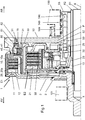
Figure 1 ] représente une vue en coupe axiale d'un double embrayage humide selon un premier mode de réalisation de l'invention. - la [
Figure 2 ] représente une autre vue en coupe axiale du double embrayage humide selon le premier mode de réalisation de l'invention. - la [
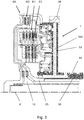
Figure 3 ] représente une vue en coupe axiale d'un triple embrayage humide comprenant le double embrayage humide selon l'invention.
- the [
Figure 1 ] shows an axial sectional view of a wet double clutch according to a first embodiment of the invention. - the [
Figure 2 ] shows another view in axial section of the wet double clutch according to the first embodiment of the invention. - the [
Figure 3 ] shows an axial sectional view of a wet triple clutch comprising the wet double clutch according to the invention.
Dans la suite de la description et des revendications, on utilisera à titre non limitatif et afin d'en faciliter la compréhension, les termes " avant " ou " arrière " selon la direction par rapport à une orientation axiale déterminée par l'axe X principal de rotation de la transmission du véhicule automobile et les termes " intérieur/ interne " ou " extérieur/ externe " par rapport à l'axe X et suivant une orientation radiale, orthogonale à ladite orientation axiale.In the remainder of the description and of the claims, the terms "front" or "rear" will be used without limitation and in order to facilitate understanding thereof in the direction with respect to an axial orientation determined by the main X axis. of the transmission of the motor vehicle and the terms “inside / inside” or “outside / outside” with respect to the X axis and in a radial orientation, orthogonal to said axial orientation.
On a représenté sur les
En relation avec les
Les deux embrayages E1, E2 comprennent des porte-disques 10, 20 d'entrée de couple lié cinématiquement avec le moteur thermique et un moyeu central 50 d'alimentation d'huile pour le premier embrayage E1 et le deuxième embrayage E2,The two clutches E1, E2 comprise torque input disc carriers 10, 20 kinematically linked with the heat engine and a central
Le moyeu central 50 d'alimentation d'huile comprend :
une portion cylindrique 55 d'axe X,un flasque 53 s'étendant radialement depuis laportion cylindrique 55,- une première cavité 51 annulaire disposée sur le côté du flasque et agencée pour recevoir un piston d'actionnement du premier embrayage E1,
- une deuxième cavité 52 annulaire disposée sur le même côté du flasque que la première cavité annulaire et agencée pour recevoir un piston d'actionnement du deuxième embrayage E2,
- des canaux d'alimentation d'huile 54a,
54b et 54c traversantla portion cylindrique 55 et le flasque 53, et débouchant dans les cavités annulaires.
- a
cylindrical portion 55 of axis X, - a
flange 53 extending radially from thecylindrical portion 55, - a first
annular cavity 51 arranged on the side of the flange and arranged to receive an actuating piston of the first clutch E1, - a second
annular cavity 52 arranged on the same side of the flange as the first annular cavity and arranged to receive an actuating piston of the second clutch E2, -
oil supply channels cylindrical portion 55 and theflange 53, and opening into the annular cavities.
Les cavités 51, 52 annulaires du premier embrayage E1 et du deuxième embrayage E2 sont orientées dans une même direction, dans cet exemple en direction de l'arbre menant, c'est-à-dire en direction du moteur thermique de la chaine de transmission de couple.The
Le moyeu central 50 d'alimentation d'huile est apte à transmettre le couple en provenance de deux sources distinctes, thermique et électrique. Le couple issu du moteur thermique et du moteur électrique peut alors être transmis auxarbres coaxiaux A1, A2 de boite de vitesses en fonction de la fermeture de l'un ou de l'autre du premier embrayage E1 ou du deuxième embrayage E2.The central
Le premier arbre A1 mené est entraîné en rotation lorsque ledit premier embrayage E1 est fermé et le deuxième A2 arbre mené est entraîné en rotation lorsque ledit deuxième embrayage E2 est fermé.The first driven shaft A1 is driven in rotation when said first clutch E1 is closed and the second driven shaft A2 is driven in rotation when said second clutch E2 is closed.
Le double embrayage humide 1 comporte autourde son axe de rotation Xau moins un élément d'entrée 2 de couple qui est lié en rotation à un arbre menant (non représenté). L'élément d'entrée 2 est situé à l'avant du double embrayage humide 1.The wet
Dans le premier mode de réalisation, l'élément d'entrée 2 présentant globalement une forme en « L », comporte une partie d'orientation radiale formée par un voile 3 d'entrée de couple et une partie d'orientation axiale formée par un moyeu 4 d'entrée de couple. Le voile 3 et le moyeu 4 sont solidaires, de préférence fixées ensemble par soudage. Le moyeu 4 d'entrée de couple est guidé en rotation à l'intérieur d'un boitier 101 fixe par rapport à la chaine de transmission de couple.In the first embodiment, the
Le moyeu 4 d'entrée de couple est par exemple lié en rotation par l'intermédiaire de cannelures formées à la sortie d'un dispositif d'amortissement (tel qu'un double volant amortisseur, etc.) dont l'entrée est liée, par l'intermédiaire notamment d'un volant moteur, à l'arbre menant formé par un vilebrequin qu'entraîne en rotation un moteur thermique équipant le véhicule automobile.The
Le voile 3 d'entrée de couple est lié en rotation avec un porte-disques 10 d'entrée de couple agencée pour recevoir l'ensemble multidisques du premierembrayage E1. La liaison en rotation est ici réalisée par soudure mais pourrait être réalisée par emboitement de cannelures.The
L'ensemble multidisques du premier embrayage E1 comporte des plateaux 11 liés en rotation à un porte-disques 10 rapporté sur le moyeu central 50 d'alimentation d'huile par l'intermédiaire d'un couvercle d'entrainement 80 et des disques 12 de friction liés en rotation à un porte-disques de sortie 13. Les disques 12 de friction sont, unitairement, axialement interposés entre deux plateaux 11 successifs.The multi-disc assembly of the first clutch E1 comprises
Dans le cas présent, le porte-disques 10 comporte une cannelure interne 10a qui engrène avec l'ensemble multidisques du premier embrayage E1, le porte-disques 10 étant fixé solidement au moyeu central 50 par l'intermédiaire d'un cordon de soudure.In the present case, the disc holder 10 comprises an internal groove 10a which meshes with the multi-disc assembly of the first clutch E1, the disc holder 10 being firmly fixed to the
Le porte-disques de sortie 13 du premier embrayage E1 est lié en rotation par engrènement avec les disques 12 de friction et par une liaison cannelée avec ledit premier arbre A1 mené. Le porte-disques de sortie 13 présente globalement une forme en « L » dont l'extrémité radiale intérieure est solidarisée à un moyeu de sortie cannelé.The
L'ensemble multidisques du deuxième embrayage E2 comporte des plateaux21 liés en rotation à un porte-disques 20 rapporté sur le moyeu central 50 d'alimentation d'huile et des disques 22 de friction liés en rotation à un porte-disques de sortie 23.The multi-disc assembly of the second clutch E2 comprises
Dans le cas présent, le porte-disques 20 comporte une cannelure interne 20a qui engrène avec l'ensemble multidisques du deuxième embrayage E2, le porte-disques20 étant fixé solidement au moyeu central 50 par l'intermédiaire d'un cordon de soudure.In the present case, the disc holder 20 comprises an internal spline 20a which meshes with the multi-disc assembly of the second clutch E2, the disc holder 20 being firmly fixed to the
Le porte-disques de sortie 23 du deuxième embrayage E2 est lié en rotation par engrènement avec les disques 22 de friction et par une liaison cannelée avec ledit deuxième arbre A2 mené. Le porte-disques de sortie 23 présente globalement une forme en « L » dont l'extrémité radiale intérieure est solidarisée à un moyeu de sortie cannelé.The
Le couvercle d'entrainement 80 est rapporté sur le pourtour extérieur du flasque 53 du moyeu central 50. Le moyeu central 50 a pour fonction de transmettre le couple au sein du double embrayage humide 1. Pour cela, le couvercle d'entrainement 80 est solidaire en rotation avec le moyeu central 50, dans le cas présent par l'intermédiaire d'un emmanchement en force.The
Le couvercle d'entrainement 80 comprend une denture externe liée cinématiquement avec la machine électrique tournante, ladite denture étant issue de matière avec le couvercle d'entrainement ou rapportée sur le couvercle d'entrainement. La denture externe présente un profil hélicoïdal de forme complémentaire au pignon de la machine électrique tournante. Alternativement, la denture pourrait présenter un profil droit de forme complémentaire à une chaine ou une courroie utilisée pour relier la machine électrique tournante.The
Le double embrayage humide 1 est commandé hydrauliquement par l'intermédiaire d'un fluide sous pression, généralement de l'huile.The wet
Pour commander sélectivement le changement d'état du premierembrayage E1 et du deuxième embrayage E2, un dispositif de commande du double embrayage humide gère l'alimentation en huile sous pression au sein de chambres de commande séparées. Le dispositif de commande est généralement intégré au carter de boite de vitesses 100. Le dispositif de commande est raccordé au moyeu central 50 d'alimentation d'huile qui comporte des canaux54a et 54c d'alimentation d'huile sous pression tel que représentés sur la
Comme cela est connu dans le fonctionnement d'un embrayage humide, une chambre d'équilibrage est associée à chaque chambre de commande. Généralement, la chambre d'équilibrage est disposée axialement à côté de la cavité annulaire faisant office de chambre de commande. Les chambres d'équilibrages sont alimentées en fluide de refroidissement. Le fluide de refroidissement emprunte un canal d'alimentation d'huile 54b distincts des autres canaux d'alimentation d'huile 54a et 54c. Ce canal d'alimentation d'huile 54b est également formé dans le moyeu central 50 d'alimentation d'huile.As is known in the operation of a wet clutch, a balancing chamber is associated with each control chamber. Generally, the balancing chamber is disposed axially next to the annular cavity acting as a control chamber. The balancing chambers are supplied with cooling fluid. The cooling fluid borrows an
Les canaux d'alimentation d'huile 54a, 54b et 54c sont répartis angulairement autour de la portion cylindrique 55. Chacun des canaux54a, 54b et 54c d'alimentation d'huile sont constitués de perçages sensiblement radiaux et axiaux dirigés en direction des chambres de commande des premier et deuxième embrayages E1, E2, mais aussi en direction des chambres d'équilibrage 31, 32 des premier et deuxième embrayages E1, E2.The
Par exemple, le canal d'alimentation d'huile 54c situé axialement à l'extrémité arrière du moyeu central 50 est associé à la chambre de commande du premier embrayage E1. Le canal d'alimentation d'huile 54c est réalisé par perçage de conduites successives axiales et radiales au sein du moyeu central 50. Les conduites sont débouchantes les unes dans les autres et agencées pour alimenter en fluide sous pression la chambre de commande du premier embrayage E1. Le canal d'alimentation d'huile 54c débouche dans la première cavité 51 annulaire formée en partie par une extension axiale issue directement du flasque 53 et en partie par le couvercle d'entrainement 80.For example, the
Notamment, le couvercle d'entrainement 80 comprend une portée cylindrique 81 intérieure pour l'appui d'un joint d'étanchéité du piston d'actionnement 15 du premier embrayage E1, la portée cylindrique 81 formant en partie la première cavité 51 annulaire.In particular, the
Le piston d'actionnement 15 du premier embrayage E1 est mobile axialement, ici de l'arrière vers l'avant, entre une position débrayée et une position embrayée qui correspondent respectivement aux états ouvert et fermé du premier embrayage E1. Le piston d'actionnement 15 est commandé en déplacement au moyen d'une chambre de commande délimitée par la première cavité 51.The
L'ensemble multidisques du premier embrayage E1 est actionné directement parle premier piston d'actionnement 15.The multi-disc assembly of the first clutch E1 is actuated directly by the
Le deuxième embrayage E2 comporte un piston d'actionnement 25 qui est mobile axialement, ici de l'arrière vers l'avant, entre une position débrayée et une position embrayée qui correspondent respectivement aux états ouvert et fermé du deuxième embrayage E2. L'ensemble multidisques du deuxième embrayage E2 est actionné directement par le deuxième piston d'actionnement 25 réalisée à partir d'une tôle emboutie. Le piston d'actionnement 25 est mobile axialement par rapport à la deuxième cavité 52 annulaire du moyeu central 50. Le piston d'actionnement 25 est commandé en déplacement au moyen d'une chambre de commande délimitée par la deuxième cavité 52.The second clutch E2 comprises an
Le canal d'alimentation d'huile 54a usiné dans le moyeu central 50 est associé à la chambre de commande du deuxième embrayage E2. Le canal d'alimentation d'huile 54a est réalisé par perçage de conduites successives axiales et radiales au sein du moyeu central 50. Les conduites sont débouchantes les unes dans les autres et agencées pour alimenter en fluide sous pression la chambre de commande du deuxième embrayage E2. Le canal d'alimentation d'huile 54b débouche dans la deuxième cavité 52 annulaire formée directement dans le moyeu central 50.The
La
Plus précisément, le premier piston d'actionnement 15 et le couvercle d'équilibrage 33 du premier embrayage E1 forment conjointement la chambre d'équilibrage 31 du premier embrayage, l'élément de rappel élastique 40 est disposé axialement entre le premier piston d'actionnement et le couvercle d'équilibrage. Le couvercle d'équilibrage 33 est fixé directement sur le flasque 53 du moyeu central 50.More precisely, the
Comme illustré sur la
A partir des
Dans une variante non représentée, afin de faciliter la réalisation du moyeu central 50, une pièce annulaire peut être rapportée sur le flasque 53 du moyeu central et comprendre au moins une portée cylindrique intérieure ou extérieure pour l'appui d'un joint d'étanchéité d'un des pistons d'actionnement du premier embrayage E1 ou du deuxième embrayage E2. Ainsi, la pièce annulaire rapportée peut former en partie la cavité annulaire de l'un des premier ou deuxième embrayages. La pièce annulaire rapportée peut être fixée par soudage sur le flasque du moyeu central, par exemple par soudage laser par transparence.In a variant not shown, in order to facilitate the production of the
Dans une autre variante non représentée, le couvercle d'entrainement 80 peut comprendre une couronne dentée décalée axialement par rapport au flasque 53 du moyeu central 50. Cette couronne dentée est toujours liée cinématiquement en rotation avec la machine électrique tournante autour d'un axe parallèle à l'axe de rotation X Dans cette variante, la couronne dentée peut être rapportée sur le couvercle d'entrainement. Ainsi la couronne dentée est décalée axialement par rapport au premier embrayage E1 et au deuxième embrayage E2 de sorte que la compacité radiale du double embrayage humide peutencore être améliorée.In another variant not shown, the
On comprend à la lecture de ce qui précède que la présente invention propose un double embrayage humide dans lequel les embrayages sont concentriques et disposées radialement dans un même plan. L'encombrement axial d'un tel double embrayage humide au sein d'une chaine de transmission de couple est réduit. Ce double embrayage humide comprend un moyeu central d'alimentation d'huile dans lequel le réseau de canaux d'alimentation d'huile est plus simple à concevoiret demande moins de temps à fabriquer.It will be understood from reading the foregoing that the present invention proposes a wet double clutch in which the clutches are concentric and arranged radially in the same plane. The axial size of such a wet double clutch within a torque transmission chain is reduced. This wet double clutch includes a central oil supply hub in which the network of oil supply channels is simpler to design and takes less time to manufacture.
L'invention ne saurait toutefois se limiter aux moyens et configurations décrits et illustrés ici, et elle s'étend également à tout moyen ou configuration équivalents et à toute combinaison technique opérant de tels moyens. En particulier, la forme du moyeu central d'alimentation d'huile peut être modifiée sans nuire à l'invention, dans la mesure où ces composants, in fine, remplissent les mêmes fonctionnalités que celles décrites dans ce document.The invention cannot however be limited to the means and configurations described and illustrated here, and it also extends to any equivalent means or configuration and to any technical combination operating such means. In particular, the shape of the central oil supply hub can be modified without harming the invention, insofar as these components, in fine, fulfill the same functionalities as those described in this document.
Le double embrayage humide selon l'invention pourrait être associé à un embrayage de coupure de type K0 qui serait dans ce cas disposé en amont de l'élément d'entrée 2 de couple. L'embrayage de coupure K0 permettrait alors de déconnecter le moteur thermique du reste de la chaine de transmission.The wet double clutch according to the invention could be associated with a K0 type cut-off clutch which would in this case be placed upstream of the
L'invention concerne également selon un autre de ses aspects un triple embrayage humide 60. Selon le mode de réalisation illustré sur la
Selon cet autre aspect de l'invention, le moyeu central 50 du double embrayage humide 1 comporte des canaux d'alimentation d'huile 54d débouchant au sein de l'embrayage de coupure de couple K0 en traversant la portion cylindrique 55 et le flasque 53. Les canaux d'alimentation d'huile 54d de l'embrayage de coupure de couple K0 sont répartis angulairement autour de l'axe de rotation Xet traversent radialement le flasque 53. La répartition angulaire autour de la portion cylindrique 55 est similaire aux canaux d'alimentation d'huile 54a, 54b et 54c des premier et deuxième embrayages E1, E2.According to this other aspect of the invention, the
Les canaux d'alimentation d'huile 54d de l'embrayage de coupure de couple k0 sont agencés selon un même plan perpendiculaire à l'axe X passant au travers du flasque 53.The
Comme illustré sur la
En complément, au moins un canal d'alimentation d'huile 54c alimentant en huile la chambre de commande du premier embrayage E1 peut être bouché par un bouchon de fermeture additionnel, par exemple une bille, un rivet ou une vis. Le bouchon de fermeture additionnel est inséré dans le canal s'étendant radialement depuis la périphérie externe du flasque 53. L'insertion du bouchon de fermeture additionnel se fait en direction de l'axe de rotation X du triple embrayage humide 60. Le bouchon de fermeture est inséré selon une direction perpendiculaire à l'axe de rotation X dans le canal d'alimentation d'huile de manière à sécuriser l'étanchéité du circuit d'alimentation d'huile du premier embrayage E1. Tous les canauxd'alimentation d'huile de la chambre de commande du premier embrayage E1 sont ainsi obturés avant emmanchementen force du couvercle d'entrainement 80 sur le flasque 53 du moyeu central 50.In addition, at least one
Dans les revendications, tout signe de référence entre parenthèses ne saurait être interprété comme une limitation de revendication.In the claims, any reference sign in parentheses cannot be interpreted as a limitation of the claim.
Claims (15)
Applications Claiming Priority (1)
| Application Number | Priority Date | Filing Date | Title |
|---|---|---|---|
| FR2002477A FR3108068B1 (en) | 2020-03-12 | 2020-03-12 | Double wet clutch |
Publications (2)
| Publication Number | Publication Date |
|---|---|
| EP3879133A1 true EP3879133A1 (en) | 2021-09-15 |
| EP3879133B1 EP3879133B1 (en) | 2023-05-03 |
Family
ID=70614221
Family Applications (1)
| Application Number | Title | Priority Date | Filing Date |
|---|---|---|---|
| EP21162134.7A Active EP3879133B1 (en) | 2020-03-12 | 2021-03-11 | Wet dual clutch |
Country Status (3)
| Country | Link |
|---|---|
| EP (1) | EP3879133B1 (en) |
| CN (1) | CN113389822A (en) |
| FR (1) | FR3108068B1 (en) |
Cited By (2)
| Publication number | Priority date | Publication date | Assignee | Title |
|---|---|---|---|---|
| WO2022207252A1 (en) * | 2021-03-29 | 2022-10-06 | Magna Pt B.V. & Co. Kg | Multi-disc clutch arrangement with sheet-metal piston for actuating the clutches, in particular a triple-disc clutch |
| EP3825568B1 (en) * | 2019-11-19 | 2023-04-26 | Valeo Embrayages | Torque transmission device |
Families Citing this family (1)
| Publication number | Priority date | Publication date | Assignee | Title |
|---|---|---|---|---|
| FR3131603A1 (en) * | 2022-01-06 | 2023-07-07 | Valeo Embrayages | Clutch module |
Citations (6)
| Publication number | Priority date | Publication date | Assignee | Title |
|---|---|---|---|---|
| FR2814121A1 (en) * | 2000-09-19 | 2002-03-22 | Peugeot Citroen Automobiles Sa | Hybrid propulsion equipment, for vehicle, comprises electric motor with outer rotor connected through one clutch to an internal combustion engine and through a second clutch to a gearbox |
| EP1750963A1 (en) * | 2004-06-03 | 2007-02-14 | Peugeot Citroen Automobiles | Transmission element for a parallel hybrid traction chain |
| DE102012006730A1 (en) | 2012-04-02 | 2013-10-02 | Borgwarner Inc. | coupling device |
| RU2670340C1 (en) * | 2017-12-05 | 2018-10-22 | Федеральное государственное унитарное предприятие "Центральный ордена Трудового Красного Знамени научно-исследовательский автомобильный и автомоторный институт "НАМИ" (ФГУП "НАМИ") | Dual clutch for vehicles transmissions |
| CN109322940B (en) * | 2018-09-05 | 2020-02-04 | 陈学琴 | Three-clutch |
| WO2021099070A1 (en) * | 2019-11-19 | 2021-05-27 | Valeo Embrayages | Assembled oil-supply hub, and triple wet clutch comprising this assembled oil-supply hub |
Family Cites Families (1)
| Publication number | Priority date | Publication date | Assignee | Title |
|---|---|---|---|---|
| DE102020105901B4 (en) * | 2020-03-05 | 2022-08-18 | Schaeffler Technologies AG & Co. KG | Double clutch with one-piece piston and inserted seals |
-
2020
- 2020-03-12 FR FR2002477A patent/FR3108068B1/en active Active
-
2021
- 2021-03-11 EP EP21162134.7A patent/EP3879133B1/en active Active
- 2021-03-12 CN CN202110268274.9A patent/CN113389822A/en active Pending
Patent Citations (6)
| Publication number | Priority date | Publication date | Assignee | Title |
|---|---|---|---|---|
| FR2814121A1 (en) * | 2000-09-19 | 2002-03-22 | Peugeot Citroen Automobiles Sa | Hybrid propulsion equipment, for vehicle, comprises electric motor with outer rotor connected through one clutch to an internal combustion engine and through a second clutch to a gearbox |
| EP1750963A1 (en) * | 2004-06-03 | 2007-02-14 | Peugeot Citroen Automobiles | Transmission element for a parallel hybrid traction chain |
| DE102012006730A1 (en) | 2012-04-02 | 2013-10-02 | Borgwarner Inc. | coupling device |
| RU2670340C1 (en) * | 2017-12-05 | 2018-10-22 | Федеральное государственное унитарное предприятие "Центральный ордена Трудового Красного Знамени научно-исследовательский автомобильный и автомоторный институт "НАМИ" (ФГУП "НАМИ") | Dual clutch for vehicles transmissions |
| CN109322940B (en) * | 2018-09-05 | 2020-02-04 | 陈学琴 | Three-clutch |
| WO2021099070A1 (en) * | 2019-11-19 | 2021-05-27 | Valeo Embrayages | Assembled oil-supply hub, and triple wet clutch comprising this assembled oil-supply hub |
Cited By (2)
| Publication number | Priority date | Publication date | Assignee | Title |
|---|---|---|---|---|
| EP3825568B1 (en) * | 2019-11-19 | 2023-04-26 | Valeo Embrayages | Torque transmission device |
| WO2022207252A1 (en) * | 2021-03-29 | 2022-10-06 | Magna Pt B.V. & Co. Kg | Multi-disc clutch arrangement with sheet-metal piston for actuating the clutches, in particular a triple-disc clutch |
Also Published As
| Publication number | Publication date |
|---|---|
| FR3108068B1 (en) | 2022-02-25 |
| FR3108068A1 (en) | 2021-09-17 |
| CN113389822A (en) | 2021-09-14 |
| EP3879133B1 (en) | 2023-05-03 |
Similar Documents
| Publication | Publication Date | Title |
|---|---|---|
| EP3879133B1 (en) | Wet dual clutch | |
| EP4062081A1 (en) | Assembled oil-supply hub, and triple wet clutch comprising this assembled oil-supply hub | |
| EP1750968B1 (en) | Double-clutch transmission element for a hybrid pull chain of a motor vehicle, method of mounting same, and motor vehicle equipped with one such element | |
| EP2998602B1 (en) | Torque transmission module intended for being provided on a transmission of a motor vehicle | |
| WO2021239693A1 (en) | Multidisc-type wet double clutch | |
| EP3899300A1 (en) | Transmission device for a motor vehicle | |
| FR3034480A1 (en) | TRANSMISSION SYSTEM COMPRISING A WET DOUBLE CLUTCH MECHANISM | |
| FR3111171A1 (en) | DOUBLE WET CLUTCH | |
| FR3079455A1 (en) | TRANSMISSION DEVICE FOR A HYBRID VEHICLE | |
| FR3078555A1 (en) | TRANSMISSION DEVICE FOR A HYBRID VEHICLE | |
| FR3090773A1 (en) | Transmission device for motor vehicle | |
| FR3060680B1 (en) | TORQUE TRANSMISSION MODULE FOR EQUIPPING MOTOR VEHICLE TRANSMISSION | |
| FR3041726A1 (en) | TORQUE TRANSMISSION ASSEMBLY FOR EQUIPPING A TRANSMISSION OF A MOTOR VEHICLE | |
| FR3092373A1 (en) | DOUBLE WET CLUTCH AND ELASTIC RETURN DEVICE FOR SUCH A DOUBLE WET CLUTCH | |
| FR3122232A1 (en) | Disc carrier assembly and wet clutch including this disc carrier assembly | |
| FR3129189A1 (en) | Improved wet clutch for powertrain system | |
| FR3115577A1 (en) | Multi-disc clutch and double wet clutch comprising such a clutch | |
| EP4261427A1 (en) | Improved wet clutch for powertrain system | |
| EP4180681A1 (en) | Improved wet clutch for powertrain system | |
| EP3564056B1 (en) | Transmission device for motor vehicle | |
| FR3078376A1 (en) | TRANSMISSION DEVICE FOR A HYBRID VEHICLE | |
| FR3078377A1 (en) | TRANSMISSION DEVICE FOR A HYBRID VEHICLE | |
| FR3130337A1 (en) | Disc carriers for a triple clutch module | |
| FR3094426A1 (en) | Transmission device for motor vehicle | |
| FR3102815A1 (en) | MULTIDISC CLUTCH MECHANISM INCLUDING IMPROVED SEALING |
Legal Events
| Date | Code | Title | Description |
|---|---|---|---|
| PUAI | Public reference made under article 153(3) epc to a published international application that has entered the european phase |
Free format text: ORIGINAL CODE: 0009012 |
|
| STAA | Information on the status of an ep patent application or granted ep patent |
Free format text: STATUS: THE APPLICATION HAS BEEN PUBLISHED |
|
| AK | Designated contracting states |
Kind code of ref document: A1 Designated state(s): AL AT BE BG CH CY CZ DE DK EE ES FI FR GB GR HR HU IE IS IT LI LT LU LV MC MK MT NL NO PL PT RO RS SE SI SK SM TR |
|
| STAA | Information on the status of an ep patent application or granted ep patent |
Free format text: STATUS: REQUEST FOR EXAMINATION WAS MADE |
|
| 17P | Request for examination filed |
Effective date: 20220302 |
|
| GRAP | Despatch of communication of intention to grant a patent |
Free format text: ORIGINAL CODE: EPIDOSNIGR1 |
|
| STAA | Information on the status of an ep patent application or granted ep patent |
Free format text: STATUS: GRANT OF PATENT IS INTENDED |
|
| INTG | Intention to grant announced |
Effective date: 20221125 |
|
| GRAS | Grant fee paid |
Free format text: ORIGINAL CODE: EPIDOSNIGR3 |
|
| GRAA | (expected) grant |
Free format text: ORIGINAL CODE: 0009210 |
|
| STAA | Information on the status of an ep patent application or granted ep patent |
Free format text: STATUS: THE PATENT HAS BEEN GRANTED |
|
| AK | Designated contracting states |
Kind code of ref document: B1 Designated state(s): AL AT BE BG CH CY CZ DE DK EE ES FI FR GB GR HR HU IE IS IT LI LT LU LV MC MK MT NL NO PL PT RO RS SE SI SK SM TR |
|
| REG | Reference to a national code |
Ref country code: GB Ref legal event code: FG4D Free format text: NOT ENGLISH |
|
| REG | Reference to a national code |
Ref country code: DE Ref legal event code: R096 Ref document number: 602021002108 Country of ref document: DE |
|
| REG | Reference to a national code |
Ref country code: AT Ref legal event code: REF Ref document number: 1564838 Country of ref document: AT Kind code of ref document: T Effective date: 20230515 Ref country code: CH Ref legal event code: EP |
|
| REG | Reference to a national code |
Ref country code: IE Ref legal event code: FG4D Free format text: LANGUAGE OF EP DOCUMENT: FRENCH |
|
| P01 | Opt-out of the competence of the unified patent court (upc) registered |
Effective date: 20230528 |
|
| REG | Reference to a national code |
Ref country code: LT Ref legal event code: MG9D |
|
| REG | Reference to a national code |
Ref country code: NL Ref legal event code: MP Effective date: 20230503 |
|
| REG | Reference to a national code |
Ref country code: AT Ref legal event code: MK05 Ref document number: 1564838 Country of ref document: AT Kind code of ref document: T Effective date: 20230503 |
|
| PG25 | Lapsed in a contracting state [announced via postgrant information from national office to epo] |
Ref country code: SE Free format text: LAPSE BECAUSE OF FAILURE TO SUBMIT A TRANSLATION OF THE DESCRIPTION OR TO PAY THE FEE WITHIN THE PRESCRIBED TIME-LIMIT Effective date: 20230503 Ref country code: PT Free format text: LAPSE BECAUSE OF FAILURE TO SUBMIT A TRANSLATION OF THE DESCRIPTION OR TO PAY THE FEE WITHIN THE PRESCRIBED TIME-LIMIT Effective date: 20230904 Ref country code: NO Free format text: LAPSE BECAUSE OF FAILURE TO SUBMIT A TRANSLATION OF THE DESCRIPTION OR TO PAY THE FEE WITHIN THE PRESCRIBED TIME-LIMIT Effective date: 20230803 Ref country code: NL Free format text: LAPSE BECAUSE OF FAILURE TO SUBMIT A TRANSLATION OF THE DESCRIPTION OR TO PAY THE FEE WITHIN THE PRESCRIBED TIME-LIMIT Effective date: 20230503 Ref country code: ES Free format text: LAPSE BECAUSE OF FAILURE TO SUBMIT A TRANSLATION OF THE DESCRIPTION OR TO PAY THE FEE WITHIN THE PRESCRIBED TIME-LIMIT Effective date: 20230503 Ref country code: AT Free format text: LAPSE BECAUSE OF FAILURE TO SUBMIT A TRANSLATION OF THE DESCRIPTION OR TO PAY THE FEE WITHIN THE PRESCRIBED TIME-LIMIT Effective date: 20230503 |
|
| PG25 | Lapsed in a contracting state [announced via postgrant information from national office to epo] |
Ref country code: RS Free format text: LAPSE BECAUSE OF FAILURE TO SUBMIT A TRANSLATION OF THE DESCRIPTION OR TO PAY THE FEE WITHIN THE PRESCRIBED TIME-LIMIT Effective date: 20230503 Ref country code: PL Free format text: LAPSE BECAUSE OF FAILURE TO SUBMIT A TRANSLATION OF THE DESCRIPTION OR TO PAY THE FEE WITHIN THE PRESCRIBED TIME-LIMIT Effective date: 20230503 Ref country code: LV Free format text: LAPSE BECAUSE OF FAILURE TO SUBMIT A TRANSLATION OF THE DESCRIPTION OR TO PAY THE FEE WITHIN THE PRESCRIBED TIME-LIMIT Effective date: 20230503 Ref country code: LT Free format text: LAPSE BECAUSE OF FAILURE TO SUBMIT A TRANSLATION OF THE DESCRIPTION OR TO PAY THE FEE WITHIN THE PRESCRIBED TIME-LIMIT Effective date: 20230503 Ref country code: IS Free format text: LAPSE BECAUSE OF FAILURE TO SUBMIT A TRANSLATION OF THE DESCRIPTION OR TO PAY THE FEE WITHIN THE PRESCRIBED TIME-LIMIT Effective date: 20230903 Ref country code: HR Free format text: LAPSE BECAUSE OF FAILURE TO SUBMIT A TRANSLATION OF THE DESCRIPTION OR TO PAY THE FEE WITHIN THE PRESCRIBED TIME-LIMIT Effective date: 20230503 Ref country code: GR Free format text: LAPSE BECAUSE OF FAILURE TO SUBMIT A TRANSLATION OF THE DESCRIPTION OR TO PAY THE FEE WITHIN THE PRESCRIBED TIME-LIMIT Effective date: 20230804 |
|
| PG25 | Lapsed in a contracting state [announced via postgrant information from national office to epo] |
Ref country code: FI Free format text: LAPSE BECAUSE OF FAILURE TO SUBMIT A TRANSLATION OF THE DESCRIPTION OR TO PAY THE FEE WITHIN THE PRESCRIBED TIME-LIMIT Effective date: 20230503 |
|
| PG25 | Lapsed in a contracting state [announced via postgrant information from national office to epo] |
Ref country code: SK Free format text: LAPSE BECAUSE OF FAILURE TO SUBMIT A TRANSLATION OF THE DESCRIPTION OR TO PAY THE FEE WITHIN THE PRESCRIBED TIME-LIMIT Effective date: 20230503 |
|
| PG25 | Lapsed in a contracting state [announced via postgrant information from national office to epo] |
Ref country code: SM Free format text: LAPSE BECAUSE OF FAILURE TO SUBMIT A TRANSLATION OF THE DESCRIPTION OR TO PAY THE FEE WITHIN THE PRESCRIBED TIME-LIMIT Effective date: 20230503 Ref country code: SK Free format text: LAPSE BECAUSE OF FAILURE TO SUBMIT A TRANSLATION OF THE DESCRIPTION OR TO PAY THE FEE WITHIN THE PRESCRIBED TIME-LIMIT Effective date: 20230503 Ref country code: RO Free format text: LAPSE BECAUSE OF FAILURE TO SUBMIT A TRANSLATION OF THE DESCRIPTION OR TO PAY THE FEE WITHIN THE PRESCRIBED TIME-LIMIT Effective date: 20230503 Ref country code: EE Free format text: LAPSE BECAUSE OF FAILURE TO SUBMIT A TRANSLATION OF THE DESCRIPTION OR TO PAY THE FEE WITHIN THE PRESCRIBED TIME-LIMIT Effective date: 20230503 Ref country code: DK Free format text: LAPSE BECAUSE OF FAILURE TO SUBMIT A TRANSLATION OF THE DESCRIPTION OR TO PAY THE FEE WITHIN THE PRESCRIBED TIME-LIMIT Effective date: 20230503 Ref country code: CZ Free format text: LAPSE BECAUSE OF FAILURE TO SUBMIT A TRANSLATION OF THE DESCRIPTION OR TO PAY THE FEE WITHIN THE PRESCRIBED TIME-LIMIT Effective date: 20230503 |
|
| REG | Reference to a national code |
Ref country code: DE Ref legal event code: R097 Ref document number: 602021002108 Country of ref document: DE |
|
| PLBE | No opposition filed within time limit |
Free format text: ORIGINAL CODE: 0009261 |
|
| STAA | Information on the status of an ep patent application or granted ep patent |
Free format text: STATUS: NO OPPOSITION FILED WITHIN TIME LIMIT |
|
| 26N | No opposition filed |
Effective date: 20240206 |