EP3879132A1 - Synchronized electromagnetic single plate clutch system - Google Patents
Synchronized electromagnetic single plate clutch system Download PDFInfo
- Publication number
- EP3879132A1 EP3879132A1 EP21250001.1A EP21250001A EP3879132A1 EP 3879132 A1 EP3879132 A1 EP 3879132A1 EP 21250001 A EP21250001 A EP 21250001A EP 3879132 A1 EP3879132 A1 EP 3879132A1
- Authority
- EP
- European Patent Office
- Prior art keywords
- clutch plate
- clutch
- synchronizer
- magnetic field
- electromagnet
- Prior art date
- Legal status (The legal status is an assumption and is not a legal conclusion. Google has not performed a legal analysis and makes no representation as to the accuracy of the status listed.)
- Granted
Links
Images




Classifications
-
- F—MECHANICAL ENGINEERING; LIGHTING; HEATING; WEAPONS; BLASTING
- F16—ENGINEERING ELEMENTS AND UNITS; GENERAL MEASURES FOR PRODUCING AND MAINTAINING EFFECTIVE FUNCTIONING OF MACHINES OR INSTALLATIONS; THERMAL INSULATION IN GENERAL
- F16D—COUPLINGS FOR TRANSMITTING ROTATION; CLUTCHES; BRAKES
- F16D27/00—Magnetically- or electrically- actuated clutches; Control or electric circuits therefor
- F16D27/10—Magnetically- or electrically- actuated clutches; Control or electric circuits therefor with an electromagnet not rotating with a clutching member, i.e. without collecting rings
- F16D27/108—Magnetically- or electrically- actuated clutches; Control or electric circuits therefor with an electromagnet not rotating with a clutching member, i.e. without collecting rings with axially movable clutching members
- F16D27/112—Magnetically- or electrically- actuated clutches; Control or electric circuits therefor with an electromagnet not rotating with a clutching member, i.e. without collecting rings with axially movable clutching members with flat friction surfaces, e.g. discs
-
- F—MECHANICAL ENGINEERING; LIGHTING; HEATING; WEAPONS; BLASTING
- F16—ENGINEERING ELEMENTS AND UNITS; GENERAL MEASURES FOR PRODUCING AND MAINTAINING EFFECTIVE FUNCTIONING OF MACHINES OR INSTALLATIONS; THERMAL INSULATION IN GENERAL
- F16D—COUPLINGS FOR TRANSMITTING ROTATION; CLUTCHES; BRAKES
- F16D23/00—Details of mechanically-actuated clutches not specific for one distinct type
- F16D23/02—Arrangements for synchronisation, also for power-operated clutches
- F16D23/04—Arrangements for synchronisation, also for power-operated clutches with an additional friction clutch
-
- F—MECHANICAL ENGINEERING; LIGHTING; HEATING; WEAPONS; BLASTING
- F16—ENGINEERING ELEMENTS AND UNITS; GENERAL MEASURES FOR PRODUCING AND MAINTAINING EFFECTIVE FUNCTIONING OF MACHINES OR INSTALLATIONS; THERMAL INSULATION IN GENERAL
- F16D—COUPLINGS FOR TRANSMITTING ROTATION; CLUTCHES; BRAKES
- F16D27/00—Magnetically- or electrically- actuated clutches; Control or electric circuits therefor
- F16D27/02—Magnetically- or electrically- actuated clutches; Control or electric circuits therefor with electromagnets incorporated in the clutch, i.e. with collecting rings
- F16D27/04—Magnetically- or electrically- actuated clutches; Control or electric circuits therefor with electromagnets incorporated in the clutch, i.e. with collecting rings with axially-movable friction surfaces
- F16D27/06—Magnetically- or electrically- actuated clutches; Control or electric circuits therefor with electromagnets incorporated in the clutch, i.e. with collecting rings with axially-movable friction surfaces with friction surfaces arranged within the flux
-
- F—MECHANICAL ENGINEERING; LIGHTING; HEATING; WEAPONS; BLASTING
- F16—ENGINEERING ELEMENTS AND UNITS; GENERAL MEASURES FOR PRODUCING AND MAINTAINING EFFECTIVE FUNCTIONING OF MACHINES OR INSTALLATIONS; THERMAL INSULATION IN GENERAL
- F16D—COUPLINGS FOR TRANSMITTING ROTATION; CLUTCHES; BRAKES
- F16D27/00—Magnetically- or electrically- actuated clutches; Control or electric circuits therefor
- F16D27/10—Magnetically- or electrically- actuated clutches; Control or electric circuits therefor with an electromagnet not rotating with a clutching member, i.e. without collecting rings
- F16D27/108—Magnetically- or electrically- actuated clutches; Control or electric circuits therefor with an electromagnet not rotating with a clutching member, i.e. without collecting rings with axially movable clutching members
- F16D27/112—Magnetically- or electrically- actuated clutches; Control or electric circuits therefor with an electromagnet not rotating with a clutching member, i.e. without collecting rings with axially movable clutching members with flat friction surfaces, e.g. discs
- F16D27/115—Magnetically- or electrically- actuated clutches; Control or electric circuits therefor with an electromagnet not rotating with a clutching member, i.e. without collecting rings with axially movable clutching members with flat friction surfaces, e.g. discs with more than two discs, e.g. multiple lamellae
-
- F—MECHANICAL ENGINEERING; LIGHTING; HEATING; WEAPONS; BLASTING
- F16—ENGINEERING ELEMENTS AND UNITS; GENERAL MEASURES FOR PRODUCING AND MAINTAINING EFFECTIVE FUNCTIONING OF MACHINES OR INSTALLATIONS; THERMAL INSULATION IN GENERAL
- F16D—COUPLINGS FOR TRANSMITTING ROTATION; CLUTCHES; BRAKES
- F16D48/00—External control of clutches
- F16D48/06—Control by electric or electronic means, e.g. of fluid pressure
- F16D48/064—Control of electrically or electromagnetically actuated clutches
-
- F—MECHANICAL ENGINEERING; LIGHTING; HEATING; WEAPONS; BLASTING
- F16—ENGINEERING ELEMENTS AND UNITS; GENERAL MEASURES FOR PRODUCING AND MAINTAINING EFFECTIVE FUNCTIONING OF MACHINES OR INSTALLATIONS; THERMAL INSULATION IN GENERAL
- F16D—COUPLINGS FOR TRANSMITTING ROTATION; CLUTCHES; BRAKES
- F16D23/00—Details of mechanically-actuated clutches not specific for one distinct type
- F16D23/02—Arrangements for synchronisation, also for power-operated clutches
- F16D23/04—Arrangements for synchronisation, also for power-operated clutches with an additional friction clutch
- F16D23/06—Arrangements for synchronisation, also for power-operated clutches with an additional friction clutch and a blocking mechanism preventing the engagement of the main clutch prior to synchronisation
- F16D2023/0687—Clutches with electrical actuation
-
- F—MECHANICAL ENGINEERING; LIGHTING; HEATING; WEAPONS; BLASTING
- F16—ENGINEERING ELEMENTS AND UNITS; GENERAL MEASURES FOR PRODUCING AND MAINTAINING EFFECTIVE FUNCTIONING OF MACHINES OR INSTALLATIONS; THERMAL INSULATION IN GENERAL
- F16D—COUPLINGS FOR TRANSMITTING ROTATION; CLUTCHES; BRAKES
- F16D27/00—Magnetically- or electrically- actuated clutches; Control or electric circuits therefor
- F16D2027/002—Electric or electronic circuits relating to actuation of electromagnetic clutches
-
- F—MECHANICAL ENGINEERING; LIGHTING; HEATING; WEAPONS; BLASTING
- F16—ENGINEERING ELEMENTS AND UNITS; GENERAL MEASURES FOR PRODUCING AND MAINTAINING EFFECTIVE FUNCTIONING OF MACHINES OR INSTALLATIONS; THERMAL INSULATION IN GENERAL
- F16D—COUPLINGS FOR TRANSMITTING ROTATION; CLUTCHES; BRAKES
- F16D27/00—Magnetically- or electrically- actuated clutches; Control or electric circuits therefor
- F16D2027/007—Bias of an armature of an electromagnetic clutch by flexing of substantially flat springs, e.g. leaf springs
-
- F—MECHANICAL ENGINEERING; LIGHTING; HEATING; WEAPONS; BLASTING
- F16—ENGINEERING ELEMENTS AND UNITS; GENERAL MEASURES FOR PRODUCING AND MAINTAINING EFFECTIVE FUNCTIONING OF MACHINES OR INSTALLATIONS; THERMAL INSULATION IN GENERAL
- F16D—COUPLINGS FOR TRANSMITTING ROTATION; CLUTCHES; BRAKES
- F16D27/00—Magnetically- or electrically- actuated clutches; Control or electric circuits therefor
- F16D2027/008—Details relating to the magnetic circuit, or to the shape of the clutch parts to achieve a certain magnetic path
-
- F—MECHANICAL ENGINEERING; LIGHTING; HEATING; WEAPONS; BLASTING
- F16—ENGINEERING ELEMENTS AND UNITS; GENERAL MEASURES FOR PRODUCING AND MAINTAINING EFFECTIVE FUNCTIONING OF MACHINES OR INSTALLATIONS; THERMAL INSULATION IN GENERAL
- F16D—COUPLINGS FOR TRANSMITTING ROTATION; CLUTCHES; BRAKES
- F16D2500/00—External control of clutches by electric or electronic means
- F16D2500/10—System to be controlled
- F16D2500/102—Actuator
- F16D2500/1021—Electrical type
- F16D2500/1022—Electromagnet
-
- F—MECHANICAL ENGINEERING; LIGHTING; HEATING; WEAPONS; BLASTING
- F16—ENGINEERING ELEMENTS AND UNITS; GENERAL MEASURES FOR PRODUCING AND MAINTAINING EFFECTIVE FUNCTIONING OF MACHINES OR INSTALLATIONS; THERMAL INSULATION IN GENERAL
- F16D—COUPLINGS FOR TRANSMITTING ROTATION; CLUTCHES; BRAKES
- F16D2500/00—External control of clutches by electric or electronic means
- F16D2500/30—Signal inputs
- F16D2500/304—Signal inputs from the clutch
- F16D2500/3041—Signal inputs from the clutch from the input shaft
- F16D2500/30415—Speed of the input shaft
-
- F—MECHANICAL ENGINEERING; LIGHTING; HEATING; WEAPONS; BLASTING
- F16—ENGINEERING ELEMENTS AND UNITS; GENERAL MEASURES FOR PRODUCING AND MAINTAINING EFFECTIVE FUNCTIONING OF MACHINES OR INSTALLATIONS; THERMAL INSULATION IN GENERAL
- F16D—COUPLINGS FOR TRANSMITTING ROTATION; CLUTCHES; BRAKES
- F16D2500/00—External control of clutches by electric or electronic means
- F16D2500/30—Signal inputs
- F16D2500/304—Signal inputs from the clutch
- F16D2500/3042—Signal inputs from the clutch from the output shaft
- F16D2500/30426—Speed of the output shaft
-
- F—MECHANICAL ENGINEERING; LIGHTING; HEATING; WEAPONS; BLASTING
- F16—ENGINEERING ELEMENTS AND UNITS; GENERAL MEASURES FOR PRODUCING AND MAINTAINING EFFECTIVE FUNCTIONING OF MACHINES OR INSTALLATIONS; THERMAL INSULATION IN GENERAL
- F16D—COUPLINGS FOR TRANSMITTING ROTATION; CLUTCHES; BRAKES
- F16D2500/00—External control of clutches by electric or electronic means
- F16D2500/50—Problem to be solved by the control system
- F16D2500/502—Relating the clutch
- F16D2500/50239—Soft clutch engagement
-
- F—MECHANICAL ENGINEERING; LIGHTING; HEATING; WEAPONS; BLASTING
- F16—ENGINEERING ELEMENTS AND UNITS; GENERAL MEASURES FOR PRODUCING AND MAINTAINING EFFECTIVE FUNCTIONING OF MACHINES OR INSTALLATIONS; THERMAL INSULATION IN GENERAL
- F16D—COUPLINGS FOR TRANSMITTING ROTATION; CLUTCHES; BRAKES
- F16D2500/00—External control of clutches by electric or electronic means
- F16D2500/50—Problem to be solved by the control system
- F16D2500/502—Relating the clutch
- F16D2500/50293—Reduction of vibrations
-
- F—MECHANICAL ENGINEERING; LIGHTING; HEATING; WEAPONS; BLASTING
- F16—ENGINEERING ELEMENTS AND UNITS; GENERAL MEASURES FOR PRODUCING AND MAINTAINING EFFECTIVE FUNCTIONING OF MACHINES OR INSTALLATIONS; THERMAL INSULATION IN GENERAL
- F16D—COUPLINGS FOR TRANSMITTING ROTATION; CLUTCHES; BRAKES
- F16D2500/00—External control of clutches by electric or electronic means
- F16D2500/70—Details about the implementation of the control system
- F16D2500/702—Look-up tables
- F16D2500/70205—Clutch actuator
- F16D2500/70223—Current
-
- F—MECHANICAL ENGINEERING; LIGHTING; HEATING; WEAPONS; BLASTING
- F16—ENGINEERING ELEMENTS AND UNITS; GENERAL MEASURES FOR PRODUCING AND MAINTAINING EFFECTIVE FUNCTIONING OF MACHINES OR INSTALLATIONS; THERMAL INSULATION IN GENERAL
- F16D—COUPLINGS FOR TRANSMITTING ROTATION; CLUTCHES; BRAKES
- F16D27/00—Magnetically- or electrically- actuated clutches; Control or electric circuits therefor
- F16D27/02—Magnetically- or electrically- actuated clutches; Control or electric circuits therefor with electromagnets incorporated in the clutch, i.e. with collecting rings
- F16D27/04—Magnetically- or electrically- actuated clutches; Control or electric circuits therefor with electromagnets incorporated in the clutch, i.e. with collecting rings with axially-movable friction surfaces
- F16D27/08—Magnetically- or electrically- actuated clutches; Control or electric circuits therefor with electromagnets incorporated in the clutch, i.e. with collecting rings with axially-movable friction surfaces with friction surfaces arranged externally to the flux
-
- F—MECHANICAL ENGINEERING; LIGHTING; HEATING; WEAPONS; BLASTING
- F16—ENGINEERING ELEMENTS AND UNITS; GENERAL MEASURES FOR PRODUCING AND MAINTAINING EFFECTIVE FUNCTIONING OF MACHINES OR INSTALLATIONS; THERMAL INSULATION IN GENERAL
- F16D—COUPLINGS FOR TRANSMITTING ROTATION; CLUTCHES; BRAKES
- F16D27/00—Magnetically- or electrically- actuated clutches; Control or electric circuits therefor
- F16D27/12—Clutch systems with a plurality of electro-magnetically-actuated clutches
Definitions
- the disclosure relates to electromagnetic clutch systems, such as synchronized electromagnetic single plate clutch systems.
- Gas turbine engines include various accessory components to enable the engine to operate, such as, for example, fuel pumps, oil pumps, electric generators and/or motors. Often, accessory components are driven by a turbine through an accessory gearbox. In some implementations, accessory components are rotationally coupled to the accessory gearbox using a mechanical clutch, which allows selective disconnection of the accessory components from the gearbox and turbine when the accessory components are not needed.
- the disclosure describes assemblies, systems, and techniques that include an electromagnetic clutch with a synchronizer.
- the electromagnetic clutch may replace a shear-limited shaft for coupling driven components to a turbine engine (e.g., through an accessory gearbox).
- the electromagnetic clutch may provide improvements over clutch assemblies, systems, or techniques without the described synchronizer.
- the synchronizer may be configured to reduce wear of the faces of the first clutch plate, the second clutch plate, or both. Additionally, debris from the shearing of a shear-limited shaft is eliminated because no shearing is needed to protect the engine by isolating the faulty component.
- the disclosure describes an electromagnetic clutch assembly that may include a first clutch plate, a second clutch plate, and a synchronizer.
- the first clutch plate and the second clutch plate may be configured to rotate about a clutch axis.
- the second clutch plate may include a first surface facing the first clutch plate and a second surface facing away from the first clutch plate.
- the second clutch plate may define an aperture extending from the first surface to the second surface.
- At least a portion of the synchronizer may be configured to extend from the second surface of the second clutch plate through the aperture.
- the first clutch plate and the first surface of the second clutch plate may define an air gap and the synchronizer may extend through the aperture from the second surface of the second clutch into the air gap.
- a surface of the synchronizer may be configured to contact the first clutch plate and the first surface of the second clutch plate may be configured to define the air gap.
- the synchronizer may be configured to translate in the aperture toward the second surface of the second clutch plate and the first clutch plate and the first surface of the second clutch plate may be configured to close the air gap.
- the disclosure describes a system that may include a first clutch plate, a second clutch plate, a synchronizer, a spring, an electromagnet, and processing circuitry.
- the first clutch plate and the second clutch plate may be configured to rotate about a clutch axis.
- the second clutch plate may include a first surface facing the first clutch plate and a second surface facing away from the first clutch plate.
- the second clutch plate may define an aperture extending from the first surface to the second surface. At least a portion of the synchronizer may be configured to extend from the second surface of the second clutch plate through the aperture.
- the spring may be configured to exert a spring force on the synchronizer in a direction toward the first clutch plate.
- the spring also may be configured to compress in response to the synchronizer translating in the aperture in the direction away from the first clutch plate.
- the electromagnet may be configured to generate a first magnetic field as a first magnetic flux passing through the first clutch plate and the second clutch plate. A first magnetic force of the first magnetic field may be less than a spring force of the spring to close the air gap.
- the electromagnet also may be configured to generate a second magnetic field as a second magnetic flux passing through the first clutch plate and the second clutch plate. A second magnetic force of the second magnetic field may be greater than a spring force of the spring to close the air gap.
- the processing circuitry may be configured to control a magnetic field generated by the electromagnet.
- the disclosure describes a method that may include rotating a first clutch plate around a clutch axis.
- the method also may include controlling an electromagnet to generate a first magnetic field to cause a synchronizer extending from a second surface of a second clutch plate facing away from the first clutch plate toward a first surface of a second clutch plate facing the first clutch plate through an aperture of defined by second clutch plate to contact the first clutch plate and generate a torque on the synchronizer.
- the first clutch plate and the second clutch plate may define an air gap.
- the method also may include controlling the electromagnet to generate a second magnetic field to cause the first surface of the second clutch plate to contact the first clutch plate.
- An example electromagnetic clutch assembly may include a first clutch plate, a second clutch plate, and a synchronizer.
- the synchronizer may be configured to extend through one or more apertures defined in the second clutch plate.
- the first clutch plate and the second clutch plate may define an air gap and the synchronizer may extend through the aperture into the air gap without contacting the first clutch plate.
- the synchronizer may be configured to contact the first clutch plate, while the first clutch plate and the second clutch plate maintain a reduced air gap.
- the synchronizer may be configured to translate in the aperture as the air gap is closed and the first clutch plate engages the second clutch plate.
- Electromagnetic clutch assemblies may be used to control engagement of system accessories, such as aircraft accessories of gas turbine engine systems. For example, restarting accessories shutdown during operation of a turbine engine may require a friction engagement to restart the accessory. During operation, engagement of an idle accessory may result in undesirable wear of clutch faces that mechanically couple the accessory to the turbine engine.
- the described electromagnetic clutch assemblies, systems, and techniques include a synchronizer configured to reduce wear of the clutch faces.
- the synchronizer may include a less abrasive material, relative to the clutch faces.
- the synchronizer may be configured to re-synchronize the accessory prior to engagement of the clutch faces.
- a spring coupled to the synchronizer may enable engagement of the synchronizer with a first clutch plate.
- an electromagnet may be used to apply a first magnetic field to the first clutch plate and a second clutch plate to begin closing an air gap between the first clutch plate and a second clutch plate by causing one or both of the first or second clutch plates to move.
- the synchronizer may protrude through the second clutch plate into the air gap.
- the synchronizer may engage the first clutch plate. Friction between the synchronizer and the first clutch plate may transfer a torque from the rotating first clutch plate to the synchronizer.
- the synchronizer may be mechanically coupled to the second clutch plate, such that the synchronizer transfers the torque to the second clutch plate to begin rotation of the second clutch plate.
- the electromagnet may apply a second magnetic field to the first clutch plate and the second clutch plate to fully close the air gap between the first clutch plate and the second clutch plate.
- the second magnetic field may be configured to generate a magnetic force sufficient to overcome a spring force of the spring coupled to the synchronizer.
- a current applied to the electromagnet may be controlled, based on a rotational speed of the first clutch plate, the second clutch plate, or both.
- the described clutch assemblies, systems, and techniques may provide smoother engagement of the first clutch plate and the second clutch plate. Smoother engagement may reduce vibration caused by engagement of the first clutch plate and the second clutch plate, compared to other clutch systems.
- the synchronizer may include a replaceable wear component, reducing maintenance costs of a clutch system. In examples in which the synchronizer includes a non-magnetic material, the non-magnetic material may reduce attraction of wear material, e.g., metals, to the electromagnet, thereby reducing wear or decreased function cause by debris build-up on the electromagnet.
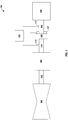
- FIG. 1 is a conceptual diagram illustrating an example system 100 including an electromagnetic clutch assembly 106.
- System 100 may include, for example, an engine 102, an accessory gear box 104, an electromagnetic clutch assembly 106, an accessory component 108 (accessory 108), and a controller 110.
- System 100 may include any suitable mechanical system.
- system 100 may include at least a portion of a mechanical system of a vehicle powered by an internal combustion engine.
- system 100 may include at least a portion of a mechanical system of an aircraft powered by a gas turbine engine.
- Engine 102 is mechanically coupled to accessory gear box 104 via drive shaft 112.
- Engine 102 is configured to rotate (e.g., drive) drive shaft 112.
- engine 102 may include other devices configured to output shaft work, such as internal combustion engines, fuel cells, electric motors or generators, pneumatic motors, or hydraulic motors.
- Drive shaft 112 may include any suitable shaft and/or gear system to transfer shaft work from engine 102 to accessory gear box 104.
- drive shaft 112 may include an internal gearbox including a direct drive, a stub shaft drive, an idler shaft drive, or other mechanical coupling configured to drive a radial drive shaft or a tower shaft.
- drive shaft 112 may include an intermediate gearbox.
- Accessory gearbox 104 is configured to transfer shaft work from drive shaft 112 to input shaft 114.
- accessory gearbox 104 may include an accessory drive of a gas turbine engine system.
- Input shaft 114 is configured to drive one or more accessories of system 100.
- system 100 may include two or more input shafts driven by drive shaft 112 via accessory gearbox 104.
- accessory gearbox 104 may include a plurality of spur gears mechanically coupling drive shaft 112 to respective input shaft of a plurality of input shafts 114, each at a selected gear ratio.
- Input shaft 114 is coupled to an output shaft 116 via an electromagnetic clutch assembly 106.
- input shaft 114 may be coupled to a first clutch plate of electromagnetic clutch assembly 106, and a second clutch plate of electromagnetic clutch assembly 106 may be coupled to output shaft 116.
- Output shaft 116 is mechanically coupled to accessory 108.
- Accessory 108 may include, for example, one or more of fuel pumps, generators, constant speed drives, oil pumps, hydraulic pumps, compressors, engine starters, tachometer sensor drives, and auxiliary gearbox drives.
- Electromagnetic clutch assembly 106 includes an electromagnet 107 configured to control engagement of electromagnetic clutch assembly 106.
- electromagnetic clutch assembly 106 may be configured to, in response to a magnetic field generated by electromagnet 107, engage (or disengage) input shaft 114 with (from) output shaft 116.
- electromagnet 107 may include an electromagnetic coil wound around a clutch axis, such as, for example, around at least a portion of output shaft 116 or input shaft 114.
- system 100 may include at least one of rotational sensors 115 and 117.
- Rotational sensors 115 and 117 are configured to sense a rotational speed of input shaft 114 (or a first clutch plate coupled to input shaft 114) and output shaft 116 (or a second clutch plate coupled to output shaft 116), respectively.
- rotational sensors 115 and/or 117 may include one or more of a reflective sensor, an interrupter sensor, an optical encoder, a variable-reluctance sensor, an eddy-current killed oscillator sensor, a Wiegand sensor, a Hall-effect sensor, or other sensors configured to detect a rotational speed of a rotating mechanical component.
- rotational sensors 115 and/or 117 may be configured to determine a rotation of input shaft 114 or output shaft 116, respectively, based on sensing a target disposed on input shaft 114 (of the first clutch plate) or output shaft 116 (or the second clutch plate).
- controller 110 may be configured to receive signals from at least one of rotational sensors 115 or 117 and control, based on a rotational speed determined based on the signal, an electrical current applied to electromagnet 107.
- Controller 110 is communicatively coupled to electromagnet 107 and configured to control the magnetic field generated by electromagnet 107.
- Controller 110 may include, for example, a computing device, a desktop computer, a laptop computer, a workstation, a server, a mainframe, a cloud computing system, a tablet, a smart phone, or the like.
- Controller 110 is configured to control operation of system 100, including, for example, electromagnet 107.
- Controller 110 may be communicatively coupled to electromagnet 107, sensors 115 and/or 117, or both using respective communication connections.
- the communication connections may include network links, such as Ethernet, ATM, or other network connections. Such connections may be wireless and/or wired connections.
- controller 110 may include control circuitry, such as one or more processors, including one or more microprocessors, digital signal processors (DSPs), application specific integrated circuits (ASICs), field programmable gate arrays (FPGAs), or any other equivalent integrated or discrete logic circuitry, as well as any combinations of such components.
- DSPs digital signal processors
- ASICs application specific integrated circuits
- FPGAs field programmable gate arrays
- controller 110 may include processing circuitry configured to determine an electrical current to apply to electromagnet 107.
- the electrical current may be based on, at least in part, a selected magnetic field, a selected magnetic flux, and/or a selected magnetic force (e.g., between at least two of the first clutch plate, the second clutch plate, or electromagnet 107).
- the electrical current may be based on, at least in part, a rotational speed determined based on one or more signals from rotational sensor 115 and/or 117. In this way, controller 110 may be configured to control the mechanical coupling of engine 102 to accessory 108.
- Electromagnetic clutch assembly 106 also includes a first clutch plate, a second clutch plate, and a synchronizer ( FIGS. 2A-2D ). Each of the first clutch plate and the second clutch plate is configured to rotate around a clutch axis. At least one of the first clutch plate or the second clutch plates is translatable in the axial direction along the clutch axis.
- the first clutch plate and the second clutch plate are positioned to define an air gap.
- the air gap may define a displacement distance between adjacent surfaces, e.g., friction surfaces, of the first clutch plate and the second clutch plate.
- the synchronizer may extend through an aperture of the second clutch into the air gap.
- the synchronizer may be translatable in the axial direction and coupled to a spring configured to urge at least a portion of the synchronizer into the air gap.
- Electromagnet 107 may be configured to generate a selected magnetic field as a selected magnetic flux passing through at least a portion of electromagnetic clutch assembly 106, e.g., the first clutch plate and the second clutch plate of electromagnetic clutch assembly 106.
- the selected magnetic field may cause axial movement of the first clutch plate toward the second clutch plate, the second clutch plate toward the first clutch plate, or both.
- electromagnet 107 may be configured to generate a first magnetic field as a first magnetic flux passing through at least a portion of electromagnetic clutch assembly 106.
- the first clutch plate and/or second clutch plate may move axially such that a surface of the synchronizer contacts the first clutch plate.
- the first clutch plate and the second clutch plate When exposed to the first magnetic field, the first clutch plate and the second clutch plate may define a reduced air gap.
- a first magnetic force of the first magnetic field may be less in magnitude than a spring force of the spring that biases the synchronizer into the air gap.
- Electromagnet 107 also may be configured to generate a second magnetic field as a second magnetic flux passing through the first clutch plate and the second clutch plate.
- the first clutch plate and/or second clutch plate move axially such that the synchronizer translates in the aperture of the second clutch in the axial direction toward the second clutch plate.
- the first clutch plate and the second clutch plate may close the air gap in response to the second magnetic field.
- the second magnetic force of the second magnetic field may be greater in magnitude than a spring force of the spring that biases the synchronizer into the air gap such that the spring force is overcome, and the air gap closes.
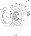
- FIGS. 2A-2D are conceptual diagrams illustrating various view of an example electromagnetic clutch assembly 106.
- electromagnetic clutch assembly 106 includes a first clutch plate 120, a second clutch plate 122, and a synchronizer 124.
- First clutch plate 120 and second clutch plate 122 may be configured to rotate about clutch axis 126.
- First clutch plate 120 and second clutch plate 122 may include any suitable material or combination of materials for forming a friction surface of a clutch plate.
- first clutch plate 120 and second clutch plate 122 may include a magnetic material, such as, for example, iron-based alloys, nickel-based alloys, cobalt-based alloys, magnetic metals or alloys, of combinations thereof.
- First clutch plate 120 includes a first surface 128 and a second surface 130.
- First surface 128 faces second clutch plate 122.
- First surface 128 may define a friction surface configured to engage second clutch plate 122.
- Second surface 130 faces away from second clutch plate 122.
- second surface 130 may define an annular recess 132.
- Annular recess 132 may be radially offset or spaced from the center of clutch axis 126.
- annular recess 132 may be configured to receive at least a portion of an electromagnet (e.g., electromagnet 107).
- Second clutch plate 122 includes a first surface 134 and a second surface 136.
- First surface 134 faces first clutch plate 120.
- First surface 134 may define a friction surface configured to engage first clutch plate 120, e.g., first surface 128.
- Second surface 136 faces away from first clutch plate 120.
- Second clutch plate 122 defines a plurality of apertures, e.g., apertures 138A, 138B, and 138C (collectively, apertures 138). Apertures 138 extend from first surface 134 of second clutch plate 122 to second surface 136 of second clutch plate 122.
- Apertures 138 may include any suitable size and/or shape to receive at least a portion of synchronizer 124 therein.
- a size and/or a shape of apertures 138 may be selected to, in the presence of a magnetic field produced by an electromagnet adjacent first clutch plate 120, control a shape of a magnetic flux of the electromagnet through second clutch plate 122.
- a size and/or a shape of apertures 138 may be selected to, in the presence of a magnetic field produced by an electromagnet adjacent first clutch plate 120, cause a magnetic flux of the electromagnet through second clutch plate 122 to weave through portions of second clutch plate 122 adjacent to apertures 138.
- apertures 137 of first clutch plate 120 and apertures 138 of second clutch plate 122 are disposed relative to each other, size, and shaped to result in magnetic flux 160 weaving through first clutch plate 120 and second clutch plate 122.
- second clutch plate 122 may define any suitable number of apertures, such as one aperture, two apertures, or four or more apertures.
- second clutch plate may define a plurality of at least partially concentric apertures (e.g., relative to clutch axis 126).
- the number and relative orientation of apertures 138 may be selected to control a shape of a magnetic flux of the electromagnet through second clutch plate 122.
- Synchronizer 124 is configured to extend from second surface 136 of second clutch plate 122 through at least one (and possibly all) of apertures 138.
- Synchronizer 124 may include any suitable material or combination of materials for forming a friction surface of a clutch plate.
- synchronizer 124 may include a non-magnetic material, such as, for example, copper, aluminum, one or more non-magnetic metal, one or more polymers, one or more ceramics, or combinations thereof.
- the non-magnetic material may include a material having a relative permeability for magnetic flux of about 1.0.
- synchronizer 124 may not change a magnetic path based on the design of first clutch plate 120 and second clutch plate 122 (e.g., position, size, and shape of apertures 137 and 138 defined in first clutch plate 120 and second clutch plate 122).
- synchronizer 124 includes an annular member 140 and protrusions 142A, 142B, and 142C (collectively, protrusions 142).
- Annular member 140 is configured to rotate about clutch axis 126, e.g., rotate together with second clutch plate 122 about clutch axis 126.
- second surface 136 may define an annular recess 139 ( FIG. 2C ) radially offset from clutch axis 126.
- Annular recess 139 may be shaped to receive at least a portion of annular member 140.
- Protrusions 142 extend from annular member 140 substantially parallel to clutch axis 126. At least one respective protrusion of protrusions 142 may extend from second surface 136 of second clutch plate 122 through a respective aperture of apertures 138.
- synchronizer 124 may include a spring configured to exert a spring force on at least a portion of synchronizer 124 in a direction toward first clutch plate 120.
- the spring may include any suitable type of spring coupled to at least a portion of synchronizer 124 and at least a portion of clutch assembly 106 that is configured to rotate with second clutch plate 122.
- synchronizer 124 may include snap ring 141 configured to apply a spring reaction loading on annular member 140.
- annular member 140 may be a spring configured to urge protrusions 142 through apertures 138 toward first clutch plate 120.
- at least a portion of annular member 140 may define or include a disc spring.
- the spring of synchronizer 124 may be configured to compress in response to synchronizer 124 translating in apertures 138 in the direction away from first clutch plate 120.
- synchronizer 124 may include a plurality of discrete synchronizers. Each respective synchronizer of the plurality of discrete synchronizers may include one or more respective protrusions configured to extend through a respective aperture of apertures 138. Each protrusion may be translatable in the axial direction. In some examples, each respective protrusion may be coupled to a respective spring configured to urge the respective protrusions toward first clutch plate 120.
- a first magnetic force of a first magnetic field generated by the electromagnet may be less in magnitude than a spring force of the spring of synchronizer 124 required to close air gap 150.
- the spring force required to close air gap 150 may be proportional to a spring constant of the spring and a length of the air gap, e.g., based on Hook's law.
- first clutch plate 120 or second clutch plate 122 may translate in the axial direction to partially close air gap 150.
- first clutch plate 120 In response to contact with a rotating first clutch plate 120, friction between first surface 128 of first clutch plate 120 and surface 143 of synchronizer 124 transfers torque from first clutch plate 120 to second clutch plate 122 via synchronizer 124. This allows rotational speed of second clutch plate 122 to synchronize with rotational speed of first clutch plate 120.
- a second magnetic force of a second magnetic field generated by the electromagnet may be greater in magnitude than a spring force of the spring of synchronizer 124 required to axially translate protrusions 142 such that surfaces of protrusions 142 are substantially co-planar with first surface 134 and air gap 150 is closed.
- first clutch plate 120 or second clutch plate 122 may translate in the axial direction to close air gap 150.
- Air gap 150 may be closed when first surface 128 of first clutch plate 120 contacts second surface 136 of second clutch plate 122.
- friction between first surface 128 of first clutch plate 120 and second surface 136 of second clutch plate 122 transfers torque from first clutch plate 120 to second clutch plate 122.
- first clutch plate 120 and second clutch plate 122 may be configured to cause magnetic flux 160 to weave between first clutch plate 120 and second clutch plate 122.
- at least one of apertures 137 in first clutch plate 120 or apertures 138 in second clutch plate 122 may be configured to cause magnetic flux 160 to flux weave between first clutch plate 120 and second clutch plate 122.
- synchronizer 124 may have a substantially negligible effect on the weaving of magnetic flux 160.
- FIG. 3 is a flow diagram illustrating an example technique for controlling engagement of an engine with an accessory using an electromagnetic clutch assembly having a synchronizer.
- the technique illustrated in FIG. 3 is described in reference to system 100 and electromagnetic clutch assembly 106 described above. However, the technique may be used to control other systems and clutch assemblies. Additionally, system 100 and electromagnetic clutch assembly 106 may be controlled using other techniques.
- the technique illustrated in FIG. 3 may include rotating a first clutch plate around a clutch axis (302).
- engine 102 may be configured to rotate, e.g., via drive shaft 112, accessory gear box 104, and input shaft 114, first clutch plate 120.
- controlling electromagnet 107 may include controlling a current applied to electromagnet 107 to generate a first magnetic field as a first magnetic flux passing through at least a portion of electromagnetic clutch assembly 106 (304).
- controlling electromagnet 107 may cause, in response to the first magnetic field, synchronizer 124 to contact first clutch plate 120 to transfer a torque to synchronizer 124.
- synchronizer 124 may extend from second surface 136 of second clutch plate 122 (e.g., second surface 136 facing away from first clutch plate 120) toward first surface 134 of second clutch plate 122 (e.g., facing first clutch plate 120) through at least one of apertures 138 defined by second clutch plate 122.
- the technique may include controlling the first magnetic field such that first clutch plate 120 and second clutch plate 122 define air gap 150, e.g., during application of the first magnetic field to first clutch plate 120 and second clutch plate 122.
- a friction at surface 143 of synchronizer 124 may transfer a force as a torque from first clutch plate 120, through synchronizer 124, to second clutch plate 122.
- transferring the torque from synchronizer 124 to second clutch plate 122 may include sensing a rotation of at least one of input shaft 114 via rotational sensor 115 or output shaft 116 via rotational sensor 117.
- transferring the torque from synchronizer 124 to second clutch plate 122 may include controlling the first magnetic field to increase the friction between synchronizer 124 and first clutch plate 120 until a rotational speed of second clutch plate 122 is within a threshold amount of a rotational speed of first clutch plate 120.
- the threshold amount may include within about 1%, 5%, 10%, or 25% of the rotational speed of first clutch plate 120.
- transferring the torque from synchronizer 124 to second clutch plate 122 may include controlling the first magnetic field to increase the friction between synchronizer 124 and first clutch plate 120 until a rotational speed of second clutch plate 122 is the same as or substantially similar to (e.g., within error of rotational sensors 115 and/or 117) a rotational speed of first clutch plate 120.
- the technique may include controlling, based on a rotation of at least one of first clutch plate 120 or second clutch plate 122, a magnetic field generated by electromagnet 107 to control an engagement of first clutch plate 120 with second clutch plate 122 via synchronizer 124.
- the technique illustrated in FIG. 3 also may include controlling electromagnet 107 to generate a second magnetic field to cause first surface 134 of second clutch plate 122 to contact first surface 128 of first clutch plate 120 (306).
- the technique may include controlling, by controller 110, a current applied to electromagnet 107 to generate a second magnetic field as a second magnetic flux passing through first clutch plate 120 and second clutch plate 122.
- the technique also may include, in response to the second magnetic field, translating synchronizer 124 in apertures 138 of second clutch plate 122 in the axial direction (e.g., toward second surface 136 of second clutch plate 122).
- the technique may include, in response to the second magnetic field, closing air gap 150 between first clutch plate 120 and second clutch plate 122.
- closing air gap 150 may include full engagement of first clutch plate 120 with second clutch plate 122.
- the technique may include determining, by rotational sensors 115 and/or 117, a rotational speed of at least one of first clutch plate 120 or second clutch plate 122.
- controlling electromagnet 107 to generate the second magnetic field may include controlling, based on the determined rotational speed of at least one of first clutch plate 120 or second clutch plate 122, electromagnet 107 to generate the second magnetic field to cause first surface 134 of second clutch plate 122 to contact first clutch plate 120.
- electromagnet 107 may apply the second magnetic field to first clutch plate 120 and second clutch plate 122 to fully close air gap 150 between first clutch plate 120 and second clutch plate 122.
Landscapes
- Engineering & Computer Science (AREA)
- General Engineering & Computer Science (AREA)
- Physics & Mathematics (AREA)
- Mechanical Engineering (AREA)
- Electromagnetism (AREA)
- Fluid Mechanics (AREA)
- Mechanical Operated Clutches (AREA)
- Hydraulic Clutches, Magnetic Clutches, Fluid Clutches, And Fluid Joints (AREA)
Abstract
Description
- The disclosure relates to electromagnetic clutch systems, such as synchronized electromagnetic single plate clutch systems.
- Gas turbine engines include various accessory components to enable the engine to operate, such as, for example, fuel pumps, oil pumps, electric generators and/or motors. Often, accessory components are driven by a turbine through an accessory gearbox. In some implementations, accessory components are rotationally coupled to the accessory gearbox using a mechanical clutch, which allows selective disconnection of the accessory components from the gearbox and turbine when the accessory components are not needed.
- The disclosure describes assemblies, systems, and techniques that include an electromagnetic clutch with a synchronizer. In some examples, the electromagnetic clutch may replace a shear-limited shaft for coupling driven components to a turbine engine (e.g., through an accessory gearbox). The electromagnetic clutch may provide improvements over clutch assemblies, systems, or techniques without the described synchronizer. For example, the synchronizer may be configured to reduce wear of the faces of the first clutch plate, the second clutch plate, or both. Additionally, debris from the shearing of a shear-limited shaft is eliminated because no shearing is needed to protect the engine by isolating the faulty component.
- In some examples, the disclosure describes an electromagnetic clutch assembly that may include a first clutch plate, a second clutch plate, and a synchronizer. The first clutch plate and the second clutch plate may be configured to rotate about a clutch axis. The second clutch plate may include a first surface facing the first clutch plate and a second surface facing away from the first clutch plate. The second clutch plate may define an aperture extending from the first surface to the second surface. At least a portion of the synchronizer may be configured to extend from the second surface of the second clutch plate through the aperture. In the absence of a magnetic field, the first clutch plate and the first surface of the second clutch plate may define an air gap and the synchronizer may extend through the aperture from the second surface of the second clutch into the air gap. In response to a first magnetic field, a surface of the synchronizer may be configured to contact the first clutch plate and the first surface of the second clutch plate may be configured to define the air gap. In response to a second magnetic field, the synchronizer may be configured to translate in the aperture toward the second surface of the second clutch plate and the first clutch plate and the first surface of the second clutch plate may be configured to close the air gap.
- In some examples, the disclosure describes a system that may include a first clutch plate, a second clutch plate, a synchronizer, a spring, an electromagnet, and processing circuitry. The first clutch plate and the second clutch plate may be configured to rotate about a clutch axis. The second clutch plate may include a first surface facing the first clutch plate and a second surface facing away from the first clutch plate. The second clutch plate may define an aperture extending from the first surface to the second surface. At least a portion of the synchronizer may be configured to extend from the second surface of the second clutch plate through the aperture. The spring may be configured to exert a spring force on the synchronizer in a direction toward the first clutch plate. The spring also may be configured to compress in response to the synchronizer translating in the aperture in the direction away from the first clutch plate. The electromagnet may be configured to generate a first magnetic field as a first magnetic flux passing through the first clutch plate and the second clutch plate. A first magnetic force of the first magnetic field may be less than a spring force of the spring to close the air gap. The electromagnet also may be configured to generate a second magnetic field as a second magnetic flux passing through the first clutch plate and the second clutch plate. A second magnetic force of the second magnetic field may be greater than a spring force of the spring to close the air gap. The processing circuitry may be configured to control a magnetic field generated by the electromagnet.
- In some examples, the disclosure describes a method that may include rotating a first clutch plate around a clutch axis. The method also may include controlling an electromagnet to generate a first magnetic field to cause a synchronizer extending from a second surface of a second clutch plate facing away from the first clutch plate toward a first surface of a second clutch plate facing the first clutch plate through an aperture of defined by second clutch plate to contact the first clutch plate and generate a torque on the synchronizer. The first clutch plate and the second clutch plate may define an air gap. The method also may include controlling the electromagnet to generate a second magnetic field to cause the first surface of the second clutch plate to contact the first clutch plate.
- The details of one or more examples are set forth in the accompanying drawings and the description below. Other features, objects, and advantages will be apparent from the description and drawings, and from the claims.
-
FIG. 1 is a conceptual diagram illustrating an example system including an electromagnetic clutch assembly having a synchronizer. -
FIGS. 2A-2D are conceptual diagrams illustrating various view of the electromagnetic clutch assembly illustrated inFIG. 1 . -
FIG. 3 is a flow diagram illustrating an example technique for controlling engagement of an engine with an accessory using an electromagnetic clutch assembly having a synchronizer. - The disclosure generally describes assemblies, systems, and techniques that include an electromagnetic clutch having a synchronizer. An example electromagnetic clutch assembly may include a first clutch plate, a second clutch plate, and a synchronizer. The synchronizer may be configured to extend through one or more apertures defined in the second clutch plate. In the absence of a magnetic field, the first clutch plate and the second clutch plate may define an air gap and the synchronizer may extend through the aperture into the air gap without contacting the first clutch plate. In response to a first magnetic field applied to the first and second clutch plates to cause the first clutch plate and/or second clutch plate to move to reduce the air gap, the synchronizer may be configured to contact the first clutch plate, while the first clutch plate and the second clutch plate maintain a reduced air gap. In response to a second (greater) magnetic field, the synchronizer may be configured to translate in the aperture as the air gap is closed and the first clutch plate engages the second clutch plate.
- Electromagnetic clutch assemblies may be used to control engagement of system accessories, such as aircraft accessories of gas turbine engine systems. For example, restarting accessories shutdown during operation of a turbine engine may require a friction engagement to restart the accessory. During operation, engagement of an idle accessory may result in undesirable wear of clutch faces that mechanically couple the accessory to the turbine engine.
- The described electromagnetic clutch assemblies, systems, and techniques include a synchronizer configured to reduce wear of the clutch faces. In some examples, the synchronizer may include a less abrasive material, relative to the clutch faces. The synchronizer may be configured to re-synchronize the accessory prior to engagement of the clutch faces. For example, a spring coupled to the synchronizer may enable engagement of the synchronizer with a first clutch plate.
- In use, an electromagnet may be used to apply a first magnetic field to the first clutch plate and a second clutch plate to begin closing an air gap between the first clutch plate and a second clutch plate by causing one or both of the first or second clutch plates to move. The synchronizer may protrude through the second clutch plate into the air gap. In response to the first magnetic field, the synchronizer may engage the first clutch plate. Friction between the synchronizer and the first clutch plate may transfer a torque from the rotating first clutch plate to the synchronizer. The synchronizer may be mechanically coupled to the second clutch plate, such that the synchronizer transfers the torque to the second clutch plate to begin rotation of the second clutch plate.
- Once a rotation of the first clutch plate and the second clutch plate is substantially synchronized, e.g., a first rotational speed of the first clutch plate and a second rotational speed the second clutch plate are the same or within a predetermined threshold amount, the electromagnet may apply a second magnetic field to the first clutch plate and the second clutch plate to fully close the air gap between the first clutch plate and the second clutch plate. For example, the second magnetic field may be configured to generate a magnetic force sufficient to overcome a spring force of the spring coupled to the synchronizer. In some examples, a current applied to the electromagnet may be controlled, based on a rotational speed of the first clutch plate, the second clutch plate, or both. In this way, total wear and/or non-uniform wear of the faces of the first clutch plate, the second clutch plate, or both may be reduced. Additionally, or alternatively, the described clutch assemblies, systems, and techniques may provide smoother engagement of the first clutch plate and the second clutch plate. Smoother engagement may reduce vibration caused by engagement of the first clutch plate and the second clutch plate, compared to other clutch systems. Additionally, or alternatively, the synchronizer may include a replaceable wear component, reducing maintenance costs of a clutch system. In examples in which the synchronizer includes a non-magnetic material, the non-magnetic material may reduce attraction of wear material, e.g., metals, to the electromagnet, thereby reducing wear or decreased function cause by debris build-up on the electromagnet.
-
FIG. 1 is a conceptual diagram illustrating anexample system 100 including an electromagneticclutch assembly 106.System 100 may include, for example, anengine 102, anaccessory gear box 104, an electromagneticclutch assembly 106, an accessory component 108 (accessory 108), and acontroller 110.System 100 may include any suitable mechanical system. In some examples,system 100 may include at least a portion of a mechanical system of a vehicle powered by an internal combustion engine. In some examples,system 100 may include at least a portion of a mechanical system of an aircraft powered by a gas turbine engine. -
Engine 102 is mechanically coupled toaccessory gear box 104 viadrive shaft 112.Engine 102 is configured to rotate (e.g., drive)drive shaft 112. Although illustrated as a gas turbine engine, in other example,engine 102 may include other devices configured to output shaft work, such as internal combustion engines, fuel cells, electric motors or generators, pneumatic motors, or hydraulic motors. - Drive
shaft 112 may include any suitable shaft and/or gear system to transfer shaft work fromengine 102 toaccessory gear box 104. In examples in whichengine 102 includes a gas turbine engine,drive shaft 112 may include an internal gearbox including a direct drive, a stub shaft drive, an idler shaft drive, or other mechanical coupling configured to drive a radial drive shaft or a tower shaft. In some examples,drive shaft 112 may include an intermediate gearbox. -
Accessory gearbox 104 is configured to transfer shaft work fromdrive shaft 112 to inputshaft 114. In some examples,accessory gearbox 104 may include an accessory drive of a gas turbine engine system.Input shaft 114 is configured to drive one or more accessories ofsystem 100. Although illustrated as asingle input shaft 114,system 100 may include two or more input shafts driven bydrive shaft 112 viaaccessory gearbox 104. For example,accessory gearbox 104 may include a plurality of spur gears mechanically couplingdrive shaft 112 to respective input shaft of a plurality ofinput shafts 114, each at a selected gear ratio. -
Input shaft 114 is coupled to anoutput shaft 116 via an electromagneticclutch assembly 106. For example,input shaft 114 may be coupled to a first clutch plate of electromagneticclutch assembly 106, and a second clutch plate of electromagneticclutch assembly 106 may be coupled tooutput shaft 116.Output shaft 116 is mechanically coupled toaccessory 108.Accessory 108 may include, for example, one or more of fuel pumps, generators, constant speed drives, oil pumps, hydraulic pumps, compressors, engine starters, tachometer sensor drives, and auxiliary gearbox drives. - Electromagnetic
clutch assembly 106 includes anelectromagnet 107 configured to control engagement of electromagneticclutch assembly 106. For example, electromagneticclutch assembly 106 may be configured to, in response to a magnetic field generated byelectromagnet 107, engage (or disengage)input shaft 114 with (from)output shaft 116. In some examples,electromagnet 107 may include an electromagnetic coil wound around a clutch axis, such as, for example, around at least a portion ofoutput shaft 116 orinput shaft 114. - In some examples,
system 100 may include at least one ofrotational sensors Rotational sensors rotational sensors 115 and/or 117 may include one or more of a reflective sensor, an interrupter sensor, an optical encoder, a variable-reluctance sensor, an eddy-current killed oscillator sensor, a Wiegand sensor, a Hall-effect sensor, or other sensors configured to detect a rotational speed of a rotating mechanical component. In some examples,rotational sensors 115 and/or 117 may be configured to determine a rotation ofinput shaft 114 oroutput shaft 116, respectively, based on sensing a target disposed on input shaft 114 (of the first clutch plate) or output shaft 116 (or the second clutch plate). In some examples,controller 110 may be configured to receive signals from at least one ofrotational sensors electromagnet 107. -
Controller 110 is communicatively coupled toelectromagnet 107 and configured to control the magnetic field generated byelectromagnet 107.Controller 110 may include, for example, a computing device, a desktop computer, a laptop computer, a workstation, a server, a mainframe, a cloud computing system, a tablet, a smart phone, or the like.Controller 110 is configured to control operation ofsystem 100, including, for example,electromagnet 107.Controller 110 may be communicatively coupled toelectromagnet 107,sensors 115 and/or 117, or both using respective communication connections. In some examples, the communication connections may include network links, such as Ethernet, ATM, or other network connections. Such connections may be wireless and/or wired connections. In other examples, the communication connections may include other types of device connections, such as USB, IEEE 1394, or the like. In some examples,controller 110 may include control circuitry, such as one or more processors, including one or more microprocessors, digital signal processors (DSPs), application specific integrated circuits (ASICs), field programmable gate arrays (FPGAs), or any other equivalent integrated or discrete logic circuitry, as well as any combinations of such components. The term "processor" or "processing circuitry" may generally refer to any of the foregoing logic circuitry, alone or in combination with other logic circuitry, or any other equivalent circuitry. For example,controller 110 may include processing circuitry configured to determine an electrical current to apply toelectromagnet 107. In some examples, the electrical current may be based on, at least in part, a selected magnetic field, a selected magnetic flux, and/or a selected magnetic force (e.g., between at least two of the first clutch plate, the second clutch plate, or electromagnet 107). In some examples, the electrical current may be based on, at least in part, a rotational speed determined based on one or more signals fromrotational sensor 115 and/or 117. In this way,controller 110 may be configured to control the mechanical coupling ofengine 102 toaccessory 108. - Electromagnetic
clutch assembly 106 also includes a first clutch plate, a second clutch plate, and a synchronizer (FIGS. 2A-2D ). Each of the first clutch plate and the second clutch plate is configured to rotate around a clutch axis. At least one of the first clutch plate or the second clutch plates is translatable in the axial direction along the clutch axis. - In the absence of a magnetic field, the first clutch plate and the second clutch plate are positioned to define an air gap. The air gap may define a displacement distance between adjacent surfaces, e.g., friction surfaces, of the first clutch plate and the second clutch plate. The synchronizer may extend through an aperture of the second clutch into the air gap. The synchronizer may be translatable in the axial direction and coupled to a spring configured to urge at least a portion of the synchronizer into the air gap.
-
Electromagnet 107 may be configured to generate a selected magnetic field as a selected magnetic flux passing through at least a portion of electromagneticclutch assembly 106, e.g., the first clutch plate and the second clutch plate of electromagneticclutch assembly 106. The selected magnetic field may cause axial movement of the first clutch plate toward the second clutch plate, the second clutch plate toward the first clutch plate, or both. For example,electromagnet 107 may be configured to generate a first magnetic field as a first magnetic flux passing through at least a portion of electromagneticclutch assembly 106. In response to the first magnetic field, the first clutch plate and/or second clutch plate may move axially such that a surface of the synchronizer contacts the first clutch plate. When exposed to the first magnetic field, the first clutch plate and the second clutch plate may define a reduced air gap. In some examples, a first magnetic force of the first magnetic field may be less in magnitude than a spring force of the spring that biases the synchronizer into the air gap. -
Electromagnet 107 also may be configured to generate a second magnetic field as a second magnetic flux passing through the first clutch plate and the second clutch plate. In response to a second magnetic field, the first clutch plate and/or second clutch plate move axially such that the synchronizer translates in the aperture of the second clutch in the axial direction toward the second clutch plate. Further, the first clutch plate and the second clutch plate may close the air gap in response to the second magnetic field. For example, the second magnetic force of the second magnetic field may be greater in magnitude than a spring force of the spring that biases the synchronizer into the air gap such that the spring force is overcome, and the air gap closes. -
FIGS. 2A-2D are conceptual diagrams illustrating various view of an example electromagneticclutch assembly 106. As illustrated inFIG. 2A , electromagneticclutch assembly 106 includes a firstclutch plate 120, a secondclutch plate 122, and asynchronizer 124. Firstclutch plate 120 and secondclutch plate 122 may be configured to rotate aboutclutch axis 126. Firstclutch plate 120 and secondclutch plate 122 may include any suitable material or combination of materials for forming a friction surface of a clutch plate. In some examples, firstclutch plate 120 and secondclutch plate 122 may include a magnetic material, such as, for example, iron-based alloys, nickel-based alloys, cobalt-based alloys, magnetic metals or alloys, of combinations thereof. - First
clutch plate 120 includes afirst surface 128 and asecond surface 130.First surface 128 faces secondclutch plate 122.First surface 128 may define a friction surface configured to engage secondclutch plate 122.Second surface 130 faces away from secondclutch plate 122. In some examples,second surface 130 may define anannular recess 132.Annular recess 132 may be radially offset or spaced from the center ofclutch axis 126. In some examples,annular recess 132 may be configured to receive at least a portion of an electromagnet (e.g., electromagnet 107). - Second
clutch plate 122 includes afirst surface 134 and asecond surface 136.First surface 134 faces firstclutch plate 120.First surface 134 may define a friction surface configured to engage firstclutch plate 120, e.g.,first surface 128.Second surface 136 faces away from firstclutch plate 120. - Second
clutch plate 122 defines a plurality of apertures, e.g., apertures 138A, 138B, and 138C (collectively, apertures 138).Apertures 138 extend fromfirst surface 134 of secondclutch plate 122 tosecond surface 136 of secondclutch plate 122. -
Apertures 138 may include any suitable size and/or shape to receive at least a portion ofsynchronizer 124 therein. In some examples, a size and/or a shape ofapertures 138 may be selected to, in the presence of a magnetic field produced by an electromagnet adjacent firstclutch plate 120, control a shape of a magnetic flux of the electromagnet through secondclutch plate 122. In some examples, a size and/or a shape ofapertures 138 may be selected to, in the presence of a magnetic field produced by an electromagnet adjacent firstclutch plate 120, cause a magnetic flux of the electromagnet through secondclutch plate 122 to weave through portions of secondclutch plate 122 adjacent to apertures 138. For example, as illustrated inFIG. 2D ,apertures 137 of firstclutch plate 120 andapertures 138 of secondclutch plate 122 are disposed relative to each other, size, and shaped to result inmagnetic flux 160 weaving through firstclutch plate 120 and secondclutch plate 122. - Although illustrated as defining three
apertures 138, in other examples, secondclutch plate 122 may define any suitable number of apertures, such as one aperture, two apertures, or four or more apertures. In some examples, second clutch plate may define a plurality of at least partially concentric apertures (e.g., relative to clutch axis 126). In some examples, the number and relative orientation ofapertures 138 may be selected to control a shape of a magnetic flux of the electromagnet through secondclutch plate 122. -
Synchronizer 124 is configured to extend fromsecond surface 136 of secondclutch plate 122 through at least one (and possibly all) ofapertures 138.Synchronizer 124 may include any suitable material or combination of materials for forming a friction surface of a clutch plate. In some examples,synchronizer 124 may include a non-magnetic material, such as, for example, copper, aluminum, one or more non-magnetic metal, one or more polymers, one or more ceramics, or combinations thereof. The non-magnetic material may include a material having a relative permeability for magnetic flux of about 1.0. By formingsynchronizer 124 from a non-magnetic material,synchronizer 124 may not affect the interaction of a magnetic field with firstclutch plate 120 and secondclutch plate 122. In this way,synchronizer 124 may not change a magnetic path based on the design of firstclutch plate 120 and second clutch plate 122 (e.g., position, size, and shape ofapertures clutch plate 120 and second clutch plate 122). - In some examples,
synchronizer 124 includes anannular member 140 andprotrusions Annular member 140 is configured to rotate aboutclutch axis 126, e.g., rotate together with secondclutch plate 122 aboutclutch axis 126. In some examples,second surface 136 may define an annular recess 139 (FIG. 2C ) radially offset fromclutch axis 126.Annular recess 139 may be shaped to receive at least a portion ofannular member 140.Protrusions 142 extend fromannular member 140 substantially parallel toclutch axis 126. At least one respective protrusion ofprotrusions 142 may extend fromsecond surface 136 of secondclutch plate 122 through a respective aperture ofapertures 138. - In some examples,
synchronizer 124 may include a spring configured to exert a spring force on at least a portion ofsynchronizer 124 in a direction toward firstclutch plate 120. In some examples, the spring may include any suitable type of spring coupled to at least a portion ofsynchronizer 124 and at least a portion ofclutch assembly 106 that is configured to rotate with secondclutch plate 122. For example, as illustrated inFIG. 2D ,synchronizer 124 may includesnap ring 141 configured to apply a spring reaction loading onannular member 140. In some examples,annular member 140 may be a spring configured to urgeprotrusions 142 throughapertures 138 toward firstclutch plate 120. For example, at least a portion ofannular member 140 may define or include a disc spring. In some examples, the spring ofsynchronizer 124 may be configured to compress in response tosynchronizer 124 translating inapertures 138 in the direction away from firstclutch plate 120. - In some examples,
synchronizer 124 may include a plurality of discrete synchronizers. Each respective synchronizer of the plurality of discrete synchronizers may include one or more respective protrusions configured to extend through a respective aperture ofapertures 138. Each protrusion may be translatable in the axial direction. In some examples, each respective protrusion may be coupled to a respective spring configured to urge the respective protrusions toward firstclutch plate 120. - In some examples, a first magnetic force of a first magnetic field generated by the electromagnet (e.g., electromagnet 107) may be less in magnitude than a spring force of the spring of
synchronizer 124 required to closeair gap 150. The spring force required to closeair gap 150 may be proportional to a spring constant of the spring and a length of the air gap, e.g., based on Hook's law. Hence, in response to the first magnetic force, at least one of firstclutch plate 120 or secondclutch plate 122 may translate in the axial direction to partiallyclose air gap 150. Once first clutch plate 120 (e.g., first surface 128) contacts surface 143 ofprotrusions 142, the first magnetic force is not sufficient to fullyclose air gap 150. In response to contact with a rotating firstclutch plate 120, friction betweenfirst surface 128 of firstclutch plate 120 andsurface 143 ofsynchronizer 124 transfers torque from firstclutch plate 120 to secondclutch plate 122 viasynchronizer 124. This allows rotational speed of secondclutch plate 122 to synchronize with rotational speed of firstclutch plate 120. - In some examples, a second magnetic force of a second magnetic field generated by the electromagnet (e.g., electromagnet 107) may be greater in magnitude than a spring force of the spring of
synchronizer 124 required to axially translateprotrusions 142 such that surfaces ofprotrusions 142 are substantially co-planar withfirst surface 134 andair gap 150 is closed. Hence, in response to the second magnetic force, at least one of firstclutch plate 120 or secondclutch plate 122 may translate in the axial direction to closeair gap 150.Air gap 150 may be closed whenfirst surface 128 of firstclutch plate 120 contactssecond surface 136 of secondclutch plate 122. In response to contact with a rotating firstclutch plate 120, friction betweenfirst surface 128 of firstclutch plate 120 andsecond surface 136 of secondclutch plate 122 transfers torque from firstclutch plate 120 to secondclutch plate 122. - In some examples, at least one of first
clutch plate 120 and secondclutch plate 122 may be configured to causemagnetic flux 160 to weave between firstclutch plate 120 and secondclutch plate 122. In some examples, at least one ofapertures 137 in firstclutch plate 120 orapertures 138 in secondclutch plate 122 may be configured to causemagnetic flux 160 to flux weave between firstclutch plate 120 and secondclutch plate 122. In examples in which synchronizer 124 includes a non-magnetic material,synchronizer 124 may have a substantially negligible effect on the weaving ofmagnetic flux 160. -
FIG. 3 is a flow diagram illustrating an example technique for controlling engagement of an engine with an accessory using an electromagnetic clutch assembly having a synchronizer. The technique illustrated inFIG. 3 is described in reference tosystem 100 and electromagneticclutch assembly 106 described above. However, the technique may be used to control other systems and clutch assemblies. Additionally,system 100 and electromagneticclutch assembly 106 may be controlled using other techniques. - The technique illustrated in
FIG. 3 may include rotating a first clutch plate around a clutch axis (302). As discussed above,engine 102 may be configured to rotate, e.g., viadrive shaft 112,accessory gear box 104, andinput shaft 114, firstclutch plate 120. - The technique illustrated in
FIG. 3 also may include controllingelectromagnet 107 to generate a selected magnetic field as a selected magnetic flux passing through at least a portion of electromagneticclutch assembly 106. For example, controllingelectromagnet 107 may include controlling a current applied toelectromagnet 107 to generate a first magnetic field as a first magnetic flux passing through at least a portion of electromagnetic clutch assembly 106 (304). In some examples, controllingelectromagnet 107 may cause, in response to the first magnetic field,synchronizer 124 to contact firstclutch plate 120 to transfer a torque tosynchronizer 124. As discussed above,synchronizer 124 may extend fromsecond surface 136 of second clutch plate 122 (e.g.,second surface 136 facing away from first clutch plate 120) towardfirst surface 134 of second clutch plate 122 (e.g., facing first clutch plate 120) through at least one ofapertures 138 defined by secondclutch plate 122. In some examples, the technique may include controlling the first magnetic field such that firstclutch plate 120 and secondclutch plate 122 defineair gap 150, e.g., during application of the first magnetic field to firstclutch plate 120 and secondclutch plate 122. - In response to contacting first
clutch plate 120, a friction atsurface 143 ofsynchronizer 124 may transfer a force as a torque from firstclutch plate 120, throughsynchronizer 124, to secondclutch plate 122. In some examples, transferring the torque fromsynchronizer 124 to secondclutch plate 122 may include sensing a rotation of at least one ofinput shaft 114 viarotational sensor 115 oroutput shaft 116 viarotational sensor 117. In some examples, transferring the torque fromsynchronizer 124 to secondclutch plate 122 may include controlling the first magnetic field to increase the friction betweensynchronizer 124 and firstclutch plate 120 until a rotational speed of secondclutch plate 122 is within a threshold amount of a rotational speed of firstclutch plate 120. For example, the threshold amount may include within about 1%, 5%, 10%, or 25% of the rotational speed of firstclutch plate 120. In some examples, transferring the torque fromsynchronizer 124 to secondclutch plate 122 may include controlling the first magnetic field to increase the friction betweensynchronizer 124 and firstclutch plate 120 until a rotational speed of secondclutch plate 122 is the same as or substantially similar to (e.g., within error ofrotational sensors 115 and/or 117) a rotational speed of firstclutch plate 120. In this way, the technique may include controlling, based on a rotation of at least one of firstclutch plate 120 or secondclutch plate 122, a magnetic field generated byelectromagnet 107 to control an engagement of firstclutch plate 120 with secondclutch plate 122 viasynchronizer 124. - The technique illustrated in
FIG. 3 also may include controllingelectromagnet 107 to generate a second magnetic field to causefirst surface 134 of secondclutch plate 122 to contactfirst surface 128 of first clutch plate 120 (306). For example, the technique may include controlling, bycontroller 110, a current applied toelectromagnet 107 to generate a second magnetic field as a second magnetic flux passing through firstclutch plate 120 and secondclutch plate 122. The technique also may include, in response to the second magnetic field, translatingsynchronizer 124 inapertures 138 of secondclutch plate 122 in the axial direction (e.g., towardsecond surface 136 of second clutch plate 122). In some examples, the technique may include, in response to the second magnetic field, closingair gap 150 between firstclutch plate 120 and secondclutch plate 122. In some examples, closingair gap 150 may include full engagement of firstclutch plate 120 with secondclutch plate 122. - In some examples, the technique may include determining, by
rotational sensors 115 and/or 117, a rotational speed of at least one of firstclutch plate 120 or secondclutch plate 122. For example, controllingelectromagnet 107 to generate the second magnetic field may include controlling, based on the determined rotational speed of at least one of firstclutch plate 120 or secondclutch plate 122,electromagnet 107 to generate the second magnetic field to causefirst surface 134 of secondclutch plate 122 to contact firstclutch plate 120. As one example, once a rotation of firstclutch plate 120 and secondclutch plate 122 is substantially synchronized, e.g., a first rotational speed of firstclutch plate 120 and a second rotational speed secondclutch plate 122 are the same or within a predetermined threshold amount,electromagnet 107 may apply the second magnetic field to firstclutch plate 120 and secondclutch plate 122 to fullyclose air gap 150 between firstclutch plate 120 and secondclutch plate 122. - The following clause illustrate examples of the subject matter described herein.
- Clause 1. An electromagnetic clutch assembly comprising: a first clutch plate configured to rotate about a clutch axis; and a second clutch plate configured to rotate about the clutch axis, the second clutch plate comprising: a first surface facing the first clutch plate; and a second surface facing away from the first clutch plate, wherein the second clutch plate defines an aperture extending from the first surface to the second surface, a synchronizer, wherein at least a portion of the synchronizer is configured to extend from the second surface of the second clutch plate through the aperture, wherein, in the absence of a magnetic field, the first clutch plate and the first surface of the second clutch plate define an air gap and the portion of the synchronizer extends through the aperture into the air gap, wherein, in response to a first magnetic field, a surface of the synchronizer is configured to contact the first clutch plate, and wherein, in response to a second magnetic field, the synchronizer is configured to translate in the aperture toward the second surface of the second clutch plate and the first clutch plate and the first surface of the second clutch plate are configured to close the air gap.
- Clause 2. The electromagnetic clutch assembly of clause 1, wherein the aperture comprises a plurality of apertures, wherein the synchronizer comprises a plurality of synchronizers, each respective synchronizer configured to extend through a respective aperture of the plurality of apertures.
- Clause 3. The electromagnetic clutch assembly of clause 1 or 2, wherein the synchronizer comprises an annular member configured to rotate about the clutch axis and at least one protrusion extending from the annular member substantially parallel to the clutch axis, and wherein the at least one protrusion extends from the second surface of the second clutch plate through the aperture.
- Clause 4. The electromagnetic clutch assembly of clause 3, wherein the second surface of the second clutch plate defines an annular recess radially offset from the clutch axis, and wherein the annular recess of the second clutch plate is shaped to receive the annular member of the synchronizer.
- Clause 5. The electromagnetic clutch assembly of any one of clauses 1 through 4, further comprising a spring configured to exert a force on the synchronizer in a direction toward the first clutch plate.
- Clause 6. The electromagnetic clutch assembly of clause 5, wherein a first magnetic force of the first magnetic field is less than a spring force of the spring to close the air gap.
- Clause 7. The electromagnetic clutch assembly of clause 5 or 6, wherein a second magnetic force of the second magnetic field is greater than a spring force of the spring to close the air gap.
- Clause 8. The electromagnetic clutch assembly of any one of clauses 1 through 7, further comprising an electromagnet configured to:
- generate the first magnetic field as a first magnetic flux passing through the first clutch plate and the second clutch plate, and
- generate the second magnetic field as a second magnetic flux passing through the first clutch plate and the second clutch plate.
- Clause 9. The electromagnetic clutch assembly of clause 8, wherein the first clutch plate and the second clutch plate are configured to cause the magnetic flux to flux weave between the first clutch plate and the second clutch plate.
- Clause 10. A system comprising: a first clutch plate configured to rotate about a clutch axis; a second clutch plate configured to rotate about the clutch axis, the second clutch plate defining an aperture extending substantially parallel to the clutch axis; a synchronizer configured to extend through the aperture toward the first clutch plate; a spring configured to exert a spring force on the synchronizer in a direction toward the first clutch plate, wherein the spring is configured to compress in response to the synchronizer translating in the aperture in the direction away from the first clutch plate; an electromagnet configured to: generate a first magnetic field as a first magnetic flux passing through the first clutch plate and the second clutch plate, wherein a first magnetic force of the first magnetic field is less than a spring force of the spring to close the air gap, and generate a second magnetic field as a second magnetic flux passing through the first clutch plate and the second clutch plate, wherein a second magnetic force of the second magnetic field is greater than a spring force of the spring to close the air gap; and processing circuitry configured to control a magnetic field generated by the electromagnet.
- Clause 11. The system of clause 10, wherein, in the absence of a magnetic field, the first clutch plate and the first surface of the second clutch plate define the air gap and the synchronizer extends through the aperture into the air gap.
- Clause 12. The system of clause 10 or 11, wherein, in response to the first magnetic field, the synchronizer is configured to contact the first clutch plate.
- Clause 13. The system of any one of clause 10 through 12, wherein, in response to the second magnetic field, the synchronizer is configured to translate in the aperture toward the second clutch plate, and the first clutch plate and the second clutch plate are configured to close the air gap.
- Clause 14. The system of any one of clause 10 through 13, wherein the processing circuitry is configured to, based at least in part on a rotational speed of the first clutch plate, cause the electromagnet to generate the second magnetic field.
- Clause 15. The system of any one of clause 10 through 14, wherein the electromagnet is wound around the clutch axis.
- Clause 16. The system of any one of clause 10 through 15, wherein at least a portion of the first clutch plate is disposed between the electromagnet and the second clutch plate.
- Clause 17. The system of any one of clause 10 through 16, further comprising an input shaft configured to rotate the first clutch plate.
- Clause 18. The system of clause 16, wherein the controller is configured to cause the electromagnet to generate the second magnetic flux based a rotational speed of the first clutch plate.
- Clause 19. A method comprising: rotating a first clutch plate around a clutch axis; controlling an electromagnet to generate a first magnetic field to cause a synchronizer extending through an aperture of defined by a second clutch plate to contact the first clutch plate and generate a torque on the synchronizer, wherein the first clutch plate and the second clutch plate define an air gap; and controlling the electromagnet to generate a second magnetic field to cause the first surface of the second clutch plate to contact the first clutch plate.
- Clause 20. The method of clause 19, wherein the method further comprises determining, by a rotational sensor, a rotational speed of at least one of the first clutch plate or the second clutch plate, wherein controlling the electromagnet to generate the second magnetic field comprises controlling, based on the determined rotational speed of at least one of the first clutch plate or the second clutch plate, the electromagnet to generate the second magnetic field to cause the first surface of the second clutch plate to contact the first clutch plate.
- Various examples have been described. These and other examples are within the scope of the following claims.
Claims (17)
- An electromagnetic clutch assembly (106) comprising:a first clutch plate (120) configured to rotate about a clutch axis (126); anda second clutch plate (122) configured to rotate about the clutch axis, the second clutch plate comprising:a first surface (128) facing the first clutch plate (120); anda second surface facing (136) away from the first clutch plate, wherein the second clutch plate defines an aperture (138) extending from the first surface to the second surface,a synchronizer (124), wherein at least a portion of the synchronizer is configured to extend from the second surface of the second clutch plate through the aperture,wherein, in the absence of a magnetic field, the first clutch plate and the first surface of the second clutch plate define an air gap (150) and the portion of the synchronizer extends through the aperture into the air gap,wherein, in response to a first magnetic field, a surface (143) of the synchronizer is configured to contact the first clutch plate, andwherein, in response to a second magnetic field, the synchronizer is configured to translate in the aperture toward the second surface of the second clutch plate and the first clutch plate and the first surface of the second clutch plate are configured to close the air gap.
- The electromagnetic clutch assembly of claim 1, wherein the aperture comprises a plurality of apertures (138A-C), wherein the synchronizer comprises a plurality of synchronizers, each respective synchronizer configured to extend through a respective aperture of the plurality of apertures.
- The electromagnetic clutch assembly of claim 1 or claim 2, wherein the synchronizer comprises an annular member (140) configured to rotate about the clutch axis and at least one protrusion extending from the annular member substantially parallel to the clutch axis, and wherein the at least one protrusion extends from the second surface of the second clutch plate through the aperture.
- The electromagnetic clutch assembly of claim 3, wherein the second surface of the second clutch plate defines an annular recess (132) radially offset from the clutch axis, and wherein the annular recess of the second clutch plate is shaped to receive the annular member of the synchronizer.
- The electromagnetic clutch assembly of any of the preceding claims, further comprising a (configured to exert a force on the synchronizer in a direction toward the first clutch plate., wherein a first magnetic force of the first magnetic field may be less than a spring force of the spring to close the air gap and a second magnetic force of the second magnetic field may be greater than a spring force of the spring to close the air gap.
- The electromagnetic clutch assembly of any of the preceding claims, further comprising an electromagnet (107) configured to:generate the first magnetic field as a first magnetic flux passing through the first clutch plate and the second clutch plate, andgenerate the second magnetic field as a second magnetic flux passing through the first clutch plate and the second clutch plate.
- The electromagnetic clutch assembly of claim 6, wherein the first clutch plate and the second clutch plate are configured to cause the magnetic flux to flux weave between the first clutch plate and the second clutch plate.
- A system comprising:a first clutch plate (120) configured to rotate about a clutch axis (126);a second clutch plate (122) configured to rotate about the clutch axis, the second clutch plate defining an aperture (138) extending substantially parallel to the clutch axis;a synchronizer (124) configured to extend through the aperture toward the first clutch plate;a spring configured to exert a spring force on the synchronizer in a direction toward the first clutch plate, wherein the spring is configured to compress in response to the synchronizer translating in the aperture in the direction away from the first clutch plate;an electromagnet (107) configured to:generate a first magnetic field as a first magnetic flux passing through the first clutch plate and the second clutch plate, wherein a first magnetic force of the first magnetic field is less than a spring force of the spring to close the air gap (150), andgenerate a second magnetic field as a second magnetic flux passing through the first clutch plate and the second clutch plate, wherein a second magnetic force of the second magnetic field is greater than a spring force of the spring to close the air gap; andprocessing circuitry (110) configured to control a magnetic field generated by the electromagnet.
- The system of claim 8, wherein, in the absence of a magnetic field, the first clutch plate and the first surface of the second clutch plate define the air gap and the synchronizer extends through the aperture into the air gap and wherein
- The system of claim 8 or claim 9, wherein, in response to the first magnetic field, the synchronizer is configured to contact the first clutch plate.
- The system of any of claims 8 to 10, wherein, in response to the second magnetic field, the synchronizer is configured to translate in the aperture toward the second clutch plate, and the first clutch plate and the second clutch plate are configured to close the air gap.
- The system of any of claims 8 to 11, wherein the processing circuitry is configured to, based at least in part on a rotational speed of the first clutch plate, cause the electromagnet to generate the second magnetic field.
- The system of any of claims 8 to 12, wherein the electromagnet is wound around the clutch axis.
- The system of any of claims 8 to 13, wherein at least a portion of the first clutch plate is disposed between the electromagnet and the second clutch plate, wherein the controller (110) may be configured to cause the electromagnet to generate the second magnetic flux based a rotational speed of the first clutch plate.
- The system of any of claims 8 to 14, further comprising an input shaft (114) configured to rotate the first clutch plate.
- A method comprising:rotating a first clutch plate (120) around a clutch axis (126);controlling an electromagnet (107) to generate a first magnetic field to cause a synchronizer (124) extending through an aperture (138) of defined by a second clutch (122) plate to contact the first clutch plate and generate a torque on the synchronizer, wherein the first clutch plate and the second clutch plate define an air gap (150); andcontrolling the electromagnet to generate a second magnetic field to cause the first surface of the second clutch plate to contact the first clutch plate.
- The method of claim 16, wherein the method further comprises determining, by a rotational sensor (115), a rotational speed of at least one of the first clutch plate or the second clutch plate, wherein controlling the electromagnet to generate the second magnetic field comprises controlling, based on the determined rotational speed of at least one of the first clutch plate or the second clutch plate, the electromagnet to generate the second magnetic field to cause the first surface of the second clutch plate to contact the first clutch plate.
Applications Claiming Priority (1)
| Application Number | Priority Date | Filing Date | Title |
|---|---|---|---|
| US16/813,242 US11137035B2 (en) | 2020-03-09 | 2020-03-09 | Synchronized electromagnetic single plate clutch system |
Publications (2)
| Publication Number | Publication Date |
|---|---|
| EP3879132A1 true EP3879132A1 (en) | 2021-09-15 |
| EP3879132B1 EP3879132B1 (en) | 2023-10-25 |
Family
ID=75223217
Family Applications (1)
| Application Number | Title | Priority Date | Filing Date |
|---|---|---|---|
| EP21250001.1A Active EP3879132B1 (en) | 2020-03-09 | 2021-03-04 | Synchronized electromagnetic single plate clutch system |
Country Status (2)
| Country | Link |
|---|---|
| US (2) | US11137035B2 (en) |
| EP (1) | EP3879132B1 (en) |
Families Citing this family (1)
| Publication number | Priority date | Publication date | Assignee | Title |
|---|---|---|---|---|
| US11137035B2 (en) | 2020-03-09 | 2021-10-05 | Rolls-Royce Corporation | Synchronized electromagnetic single plate clutch system |
Citations (3)
| Publication number | Priority date | Publication date | Assignee | Title |
|---|---|---|---|---|
| GB842395A (en) * | 1956-02-25 | 1960-07-27 | Zahnradfabrik Friedrichshafen | Improvements in and relating to positive clutches |
| FR2112864A5 (en) * | 1970-11-10 | 1972-06-23 | Creusot Loire | |
| CN108506365A (en) * | 2018-02-26 | 2018-09-07 | 海宁萃智智能机器人有限公司 | A kind of novel clutch |
Family Cites Families (36)
| Publication number | Priority date | Publication date | Assignee | Title |
|---|---|---|---|---|
| US2579318A (en) | 1950-12-28 | 1951-12-18 | Gen Electric | Rotor for dynamoelectric machine |
| US2796963A (en) | 1956-03-08 | 1957-06-25 | Esther M Harter | Magnetic clutch with stationary winding |
| US3016667A (en) | 1959-01-22 | 1962-01-16 | Kerhoas Lucien Yves | Machine for packaging under thermoplastic film |
| GB1320038A (en) * | 1969-12-10 | 1973-06-13 | Creusot Loire | Electromagnetic clutches |
| US4030583A (en) | 1975-09-11 | 1977-06-21 | Facet Enterprises, Inc. | Fail safe electric cone clutch |
| JPS5937565A (en) | 1982-08-27 | 1984-03-01 | Konishiroku Photo Ind Co Ltd | Paper feeding member controller of optical exposure system driving device |
| US4561520A (en) * | 1983-11-03 | 1985-12-31 | Borg-Warner Corporation | Magnetically synchronized clutch apparatus |
| JPS62500877A (en) * | 1984-11-06 | 1987-04-09 | ツア−ンラトフアブリク フリ−トリツヒシヤフエン アクチエンゲゼルシヤフト | Electromagnetic pawl clutch for automotive differential toothing |
| US4891619A (en) | 1987-12-14 | 1990-01-02 | Dana Corporation | Electromagnetic coupling disc |
| WO1991016552A2 (en) | 1990-04-24 | 1991-10-31 | Tesma International Inc. | Electromagnetic clutch with improved rotor |
| US5052534A (en) * | 1990-10-30 | 1991-10-01 | Dana Corporation | Electromagnetic synchronizing and shifting clutch |
| US5465819A (en) | 1992-09-29 | 1995-11-14 | Borg-Warner Automotive, Inc. | Power transmitting assembly |
| US5320206A (en) | 1993-05-03 | 1994-06-14 | Ogura Corporation | Coil mounting and terminals for an electromagnetic clutch |
| JPH07269603A (en) | 1994-03-28 | 1995-10-20 | Aisin Seiki Co Ltd | Method for synchronizing rat tooth electromagnetic clutch, synchronizer for mouse tooth electromagnetic clutch, and throttle control device |
| DE19532135A1 (en) | 1995-08-31 | 1997-03-06 | Clouth Gummiwerke Ag | Drive system, in particular for a motor vehicle, and method for operating the same |
| DE19532136A1 (en) | 1995-08-31 | 1997-03-06 | Clouth Gummiwerke Ag | Drive system, in particular for a motor vehicle, and method for operating the same |
| DE19532164A1 (en) | 1995-08-31 | 1997-03-06 | Clouth Gummiwerke Ag | Drive system, in particular for a motor vehicle, and method for operating the same |
| EP0846065B1 (en) | 1995-08-31 | 2001-11-07 | Continental ISAD Electronic Systems GmbH & Co. oHG | Traction control system for a motor vehicle, using an electrical machine |
| DE19532163A1 (en) | 1995-08-31 | 1997-03-06 | Clouth Gummiwerke Ag | System for actively reducing speed non-uniformities of IC engine drive-shaft |
| DE69630846T2 (en) | 1995-09-15 | 2004-11-04 | Pdc International Corp., Norwalk | Method and device for applying tapes to objects |
| US5737900A (en) | 1995-09-15 | 1998-04-14 | Pdc International Corporation | Banding method and apparatus with acceleration of band along floating mandrel aimed toward article to be banded |
| US5915513A (en) | 1997-08-26 | 1999-06-29 | Borg-Warner Automotive, Inc. | Clutch with magneto-rheological operator for transfer cases and the like |
| US6127754A (en) | 1998-03-30 | 2000-10-03 | Dana Corporation | Master synchronizer motor |
| JP2003095505A (en) | 2001-09-21 | 2003-04-03 | Toshiba Corp | Switchback device |
| US6602159B1 (en) | 2002-02-05 | 2003-08-05 | New Venture Gear, Inc. | On-demand transfer case with integrated sprocket and bi-directional clutch assembly |
| US20040180747A1 (en) | 2003-03-14 | 2004-09-16 | Weilant David R. | Transfer case having input shaft electromagnetic brake |
| JP2004308903A (en) | 2003-04-07 | 2004-11-04 | Luk Lamellen & Kupplungsbau Beteiligungs Kg | Electromagnetic friction clutch |
| US7681704B2 (en) | 2004-01-20 | 2010-03-23 | Eaton Corporation | Electromagnetic inertia brake for a power input shaft of a power transmission mechanism |
| DE102004046600A1 (en) | 2004-09-25 | 2006-03-30 | Valeo Sicherheitssysteme Gmbh | Self-actuating swivel coupling |
| GR1005191B (en) | 2005-06-06 | 2006-04-14 | Αντωνιος Μαστροκαλος | Automatic continuous transmission gear box of infinite speed ratios with hydraulic or electromagnetic clutch |
| JP2009121676A (en) | 2007-10-26 | 2009-06-04 | Denso Corp | Power transmission device |
| ES2660968T3 (en) | 2011-08-25 | 2018-03-26 | Warner Electric Technology Llc | Swivel coupling device |
| CN103032541B (en) | 2012-12-11 | 2015-09-30 | 王俊生 | Eccentric type planet wheel planetary pinion timing clutch |
| CN103042942B (en) | 2012-12-24 | 2016-04-27 | 联合汽车电子有限公司 | Adopt a/c system and the control method of the stroke-increasing electric automobile of synchro |
| US10107340B1 (en) * | 2017-04-05 | 2018-10-23 | GM Global Technology Operations LLC | Device for activating a low-friction clutch |
| US11137035B2 (en) | 2020-03-09 | 2021-10-05 | Rolls-Royce Corporation | Synchronized electromagnetic single plate clutch system |
-
2020
- 2020-03-09 US US16/813,242 patent/US11137035B2/en active Active
-
2021
- 2021-03-04 EP EP21250001.1A patent/EP3879132B1/en active Active
- 2021-09-29 US US17/449,370 patent/US11480221B2/en active Active
Patent Citations (3)
| Publication number | Priority date | Publication date | Assignee | Title |
|---|---|---|---|---|
| GB842395A (en) * | 1956-02-25 | 1960-07-27 | Zahnradfabrik Friedrichshafen | Improvements in and relating to positive clutches |
| FR2112864A5 (en) * | 1970-11-10 | 1972-06-23 | Creusot Loire | |
| CN108506365A (en) * | 2018-02-26 | 2018-09-07 | 海宁萃智智能机器人有限公司 | A kind of novel clutch |
Also Published As
| Publication number | Publication date |
|---|---|
| EP3879132B1 (en) | 2023-10-25 |
| US20220018401A1 (en) | 2022-01-20 |
| US11137035B2 (en) | 2021-10-05 |
| US20210277961A1 (en) | 2021-09-09 |
| US11480221B2 (en) | 2022-10-25 |
Similar Documents
| Publication | Publication Date | Title |
|---|---|---|
| EP3256751B1 (en) | A brake with a reed switch for indicating an operating condition of the brake | |
| US5052534A (en) | Electromagnetic synchronizing and shifting clutch | |
| EP1274164B1 (en) | Vane actuator | |
| EP3319212B1 (en) | Electrical machine | |
| CN115451035A (en) | Breaking and connecting device | |
| US11480221B2 (en) | Synchronized electromagnetic single plate clutch system | |
| EP3309421B1 (en) | Generator disconnect couplings | |
| CN113267335A (en) | Precision speed reducer return difference testing device | |
| EP2803878B1 (en) | Electromagnetic driving device and methods for manufacturing and controlling same | |
| US3830349A (en) | Method and apparatus for engaging coacting propulsion systems | |
| US20190118936A1 (en) | Pitch actuation system for a turbomachine propeller | |
| CN111810254B (en) | Induced draft fan steam-electricity dual-drive system and operation control method thereof | |
| US2772762A (en) | Magnetic drive | |
| US2597388A (en) | Electromagnetic clutch | |
| US11466735B2 (en) | Electromagnetic clutch system | |
| CN205693545U (en) | Totally-enclosed anti-foreign body intrusion limited-moment permanent magnetic coupling | |
| US12234777B2 (en) | Offset clutch mechanism for electric starting and barring motor of a gas-turbine engine | |
| US2982805A (en) | Ignition system for internal combustion engines | |
| CN211557121U (en) | A synchronous permanent magnet coupling with single permanent magnet rotor | |
| GB2592977A (en) | Generator accessory drive | |
| EP4332406B1 (en) | Brake for motor | |
| TWI920223B (en) | Brake for motor | |
| EP4502412A1 (en) | Brake with integrated motor position sensor | |
| EP3681024B1 (en) | Electrical machine disconnection systems | |
| SU1472714A1 (en) | Magnetic clutch |
Legal Events
| Date | Code | Title | Description |
|---|---|---|---|
| PUAI | Public reference made under article 153(3) epc to a published international application that has entered the european phase |
Free format text: ORIGINAL CODE: 0009012 |
|
| STAA | Information on the status of an ep patent application or granted ep patent |
Free format text: STATUS: THE APPLICATION HAS BEEN PUBLISHED |
|
| AK | Designated contracting states |
Kind code of ref document: A1 Designated state(s): AL AT BE BG CH CY CZ DE DK EE ES FI FR GB GR HR HU IE IS IT LI LT LU LV MC MK MT NL NO PL PT RO RS SE SI SK SM TR |
|
| STAA | Information on the status of an ep patent application or granted ep patent |
Free format text: STATUS: REQUEST FOR EXAMINATION WAS MADE |
|
| 17P | Request for examination filed |
Effective date: 20220311 |
|
| RBV | Designated contracting states (corrected) |
Designated state(s): AL AT BE BG CH CY CZ DE DK EE ES FI FR GB GR HR HU IE IS IT LI LT LU LV MC MK MT NL NO PL PT RO RS SE SI SK SM TR |
|
| GRAP | Despatch of communication of intention to grant a patent |
Free format text: ORIGINAL CODE: EPIDOSNIGR1 |
|
| STAA | Information on the status of an ep patent application or granted ep patent |
Free format text: STATUS: GRANT OF PATENT IS INTENDED |
|
| INTG | Intention to grant announced |
Effective date: 20230803 |
|
| GRAS | Grant fee paid |
Free format text: ORIGINAL CODE: EPIDOSNIGR3 |
|
| GRAA | (expected) grant |
Free format text: ORIGINAL CODE: 0009210 |
|
| STAA | Information on the status of an ep patent application or granted ep patent |
Free format text: STATUS: THE PATENT HAS BEEN GRANTED |
|
| P01 | Opt-out of the competence of the unified patent court (upc) registered |
Effective date: 20230904 |
|
| AK | Designated contracting states |
Kind code of ref document: B1 Designated state(s): AL AT BE BG CH CY CZ DE DK EE ES FI FR GB GR HR HU IE IS IT LI LT LU LV MC MK MT NL NO PL PT RO RS SE SI SK SM TR |
|
| REG | Reference to a national code |
Ref country code: GB Ref legal event code: FG4D |
|
| REG | Reference to a national code |
Ref country code: CH Ref legal event code: EP |
|
| REG | Reference to a national code |
Ref country code: DE Ref legal event code: R096 Ref document number: 602021006213 Country of ref document: DE |
|
| REG | Reference to a national code |
Ref country code: IE Ref legal event code: FG4D |
|
| REG | Reference to a national code |
Ref country code: LT Ref legal event code: MG9D |
|
| REG | Reference to a national code |
Ref country code: NL Ref legal event code: MP Effective date: 20231025 |
|
| REG | Reference to a national code |
Ref country code: AT Ref legal event code: MK05 Ref document number: 1624944 Country of ref document: AT Kind code of ref document: T Effective date: 20231025 |
|
| PG25 | Lapsed in a contracting state [announced via postgrant information from national office to epo] |
Ref country code: NL Free format text: LAPSE BECAUSE OF FAILURE TO SUBMIT A TRANSLATION OF THE DESCRIPTION OR TO PAY THE FEE WITHIN THE PRESCRIBED TIME-LIMIT Effective date: 20231025 |
|
| PG25 | Lapsed in a contracting state [announced via postgrant information from national office to epo] |
Ref country code: GR Free format text: LAPSE BECAUSE OF FAILURE TO SUBMIT A TRANSLATION OF THE DESCRIPTION OR TO PAY THE FEE WITHIN THE PRESCRIBED TIME-LIMIT Effective date: 20240126 |
|
| PG25 | Lapsed in a contracting state [announced via postgrant information from national office to epo] |
Ref country code: IS Free format text: LAPSE BECAUSE OF FAILURE TO SUBMIT A TRANSLATION OF THE DESCRIPTION OR TO PAY THE FEE WITHIN THE PRESCRIBED TIME-LIMIT Effective date: 20240225 |
|
| PG25 | Lapsed in a contracting state [announced via postgrant information from national office to epo] |
Ref country code: LT Free format text: LAPSE BECAUSE OF FAILURE TO SUBMIT A TRANSLATION OF THE DESCRIPTION OR TO PAY THE FEE WITHIN THE PRESCRIBED TIME-LIMIT Effective date: 20231025 |
|
| PG25 | Lapsed in a contracting state [announced via postgrant information from national office to epo] |
Ref country code: AT Free format text: LAPSE BECAUSE OF FAILURE TO SUBMIT A TRANSLATION OF THE DESCRIPTION OR TO PAY THE FEE WITHIN THE PRESCRIBED TIME-LIMIT Effective date: 20231025 |
|
| PG25 | Lapsed in a contracting state [announced via postgrant information from national office to epo] |
Ref country code: ES Free format text: LAPSE BECAUSE OF FAILURE TO SUBMIT A TRANSLATION OF THE DESCRIPTION OR TO PAY THE FEE WITHIN THE PRESCRIBED TIME-LIMIT Effective date: 20231025 |
|
| PG25 | Lapsed in a contracting state [announced via postgrant information from national office to epo] |
Ref country code: LT Free format text: LAPSE BECAUSE OF FAILURE TO SUBMIT A TRANSLATION OF THE DESCRIPTION OR TO PAY THE FEE WITHIN THE PRESCRIBED TIME-LIMIT Effective date: 20231025 Ref country code: IS Free format text: LAPSE BECAUSE OF FAILURE TO SUBMIT A TRANSLATION OF THE DESCRIPTION OR TO PAY THE FEE WITHIN THE PRESCRIBED TIME-LIMIT Effective date: 20240225 Ref country code: GR Free format text: LAPSE BECAUSE OF FAILURE TO SUBMIT A TRANSLATION OF THE DESCRIPTION OR TO PAY THE FEE WITHIN THE PRESCRIBED TIME-LIMIT Effective date: 20240126 Ref country code: ES Free format text: LAPSE BECAUSE OF FAILURE TO SUBMIT A TRANSLATION OF THE DESCRIPTION OR TO PAY THE FEE WITHIN THE PRESCRIBED TIME-LIMIT Effective date: 20231025 Ref country code: BG Free format text: LAPSE BECAUSE OF FAILURE TO SUBMIT A TRANSLATION OF THE DESCRIPTION OR TO PAY THE FEE WITHIN THE PRESCRIBED TIME-LIMIT Effective date: 20240125 Ref country code: AT Free format text: LAPSE BECAUSE OF FAILURE TO SUBMIT A TRANSLATION OF THE DESCRIPTION OR TO PAY THE FEE WITHIN THE PRESCRIBED TIME-LIMIT Effective date: 20231025 Ref country code: PT Free format text: LAPSE BECAUSE OF FAILURE TO SUBMIT A TRANSLATION OF THE DESCRIPTION OR TO PAY THE FEE WITHIN THE PRESCRIBED TIME-LIMIT Effective date: 20240226 |
|
| PGFP | Annual fee paid to national office [announced via postgrant information from national office to epo] |
Ref country code: DE Payment date: 20240328 Year of fee payment: 4 |
|
| PG25 | Lapsed in a contracting state [announced via postgrant information from national office to epo] |
Ref country code: SE Free format text: LAPSE BECAUSE OF FAILURE TO SUBMIT A TRANSLATION OF THE DESCRIPTION OR TO PAY THE FEE WITHIN THE PRESCRIBED TIME-LIMIT Effective date: 20231025 Ref country code: RS Free format text: LAPSE BECAUSE OF FAILURE TO SUBMIT A TRANSLATION OF THE DESCRIPTION OR TO PAY THE FEE WITHIN THE PRESCRIBED TIME-LIMIT Effective date: 20231025 Ref country code: PL Free format text: LAPSE BECAUSE OF FAILURE TO SUBMIT A TRANSLATION OF THE DESCRIPTION OR TO PAY THE FEE WITHIN THE PRESCRIBED TIME-LIMIT Effective date: 20231025 Ref country code: NO Free format text: LAPSE BECAUSE OF FAILURE TO SUBMIT A TRANSLATION OF THE DESCRIPTION OR TO PAY THE FEE WITHIN THE PRESCRIBED TIME-LIMIT Effective date: 20240125 Ref country code: LV Free format text: LAPSE BECAUSE OF FAILURE TO SUBMIT A TRANSLATION OF THE DESCRIPTION OR TO PAY THE FEE WITHIN THE PRESCRIBED TIME-LIMIT Effective date: 20231025 Ref country code: HR Free format text: LAPSE BECAUSE OF FAILURE TO SUBMIT A TRANSLATION OF THE DESCRIPTION OR TO PAY THE FEE WITHIN THE PRESCRIBED TIME-LIMIT Effective date: 20231025 |
|
| PGFP | Annual fee paid to national office [announced via postgrant information from national office to epo] |
Ref country code: FR Payment date: 20240327 Year of fee payment: 4 |
|
| PG25 | Lapsed in a contracting state [announced via postgrant information from national office to epo] |
Ref country code: DK Free format text: LAPSE BECAUSE OF FAILURE TO SUBMIT A TRANSLATION OF THE DESCRIPTION OR TO PAY THE FEE WITHIN THE PRESCRIBED TIME-LIMIT Effective date: 20231025 |
|
| PG25 | Lapsed in a contracting state [announced via postgrant information from national office to epo] |
Ref country code: CZ Free format text: LAPSE BECAUSE OF FAILURE TO SUBMIT A TRANSLATION OF THE DESCRIPTION OR TO PAY THE FEE WITHIN THE PRESCRIBED TIME-LIMIT Effective date: 20231025 |
|
| REG | Reference to a national code |
Ref country code: DE Ref legal event code: R097 Ref document number: 602021006213 Country of ref document: DE |
|
| PG25 | Lapsed in a contracting state [announced via postgrant information from national office to epo] |
Ref country code: SK Free format text: LAPSE BECAUSE OF FAILURE TO SUBMIT A TRANSLATION OF THE DESCRIPTION OR TO PAY THE FEE WITHIN THE PRESCRIBED TIME-LIMIT Effective date: 20231025 |
|
| PG25 | Lapsed in a contracting state [announced via postgrant information from national office to epo] |
Ref country code: SM Free format text: LAPSE BECAUSE OF FAILURE TO SUBMIT A TRANSLATION OF THE DESCRIPTION OR TO PAY THE FEE WITHIN THE PRESCRIBED TIME-LIMIT Effective date: 20231025 Ref country code: SK Free format text: LAPSE BECAUSE OF FAILURE TO SUBMIT A TRANSLATION OF THE DESCRIPTION OR TO PAY THE FEE WITHIN THE PRESCRIBED TIME-LIMIT Effective date: 20231025 Ref country code: RO Free format text: LAPSE BECAUSE OF FAILURE TO SUBMIT A TRANSLATION OF THE DESCRIPTION OR TO PAY THE FEE WITHIN THE PRESCRIBED TIME-LIMIT Effective date: 20231025 Ref country code: IT Free format text: LAPSE BECAUSE OF FAILURE TO SUBMIT A TRANSLATION OF THE DESCRIPTION OR TO PAY THE FEE WITHIN THE PRESCRIBED TIME-LIMIT Effective date: 20231025 Ref country code: EE Free format text: LAPSE BECAUSE OF FAILURE TO SUBMIT A TRANSLATION OF THE DESCRIPTION OR TO PAY THE FEE WITHIN THE PRESCRIBED TIME-LIMIT Effective date: 20231025 Ref country code: DK Free format text: LAPSE BECAUSE OF FAILURE TO SUBMIT A TRANSLATION OF THE DESCRIPTION OR TO PAY THE FEE WITHIN THE PRESCRIBED TIME-LIMIT Effective date: 20231025 Ref country code: CZ Free format text: LAPSE BECAUSE OF FAILURE TO SUBMIT A TRANSLATION OF THE DESCRIPTION OR TO PAY THE FEE WITHIN THE PRESCRIBED TIME-LIMIT Effective date: 20231025 |
|
| PLBE | No opposition filed within time limit |
Free format text: ORIGINAL CODE: 0009261 |
|
| STAA | Information on the status of an ep patent application or granted ep patent |
Free format text: STATUS: NO OPPOSITION FILED WITHIN TIME LIMIT |
|
| 26N | No opposition filed |
Effective date: 20240726 |
|
| PG25 | Lapsed in a contracting state [announced via postgrant information from national office to epo] |
Ref country code: SI Free format text: LAPSE BECAUSE OF FAILURE TO SUBMIT A TRANSLATION OF THE DESCRIPTION OR TO PAY THE FEE WITHIN THE PRESCRIBED TIME-LIMIT Effective date: 20231025 |
|
| PG25 | Lapsed in a contracting state [announced via postgrant information from national office to epo] |
Ref country code: SI Free format text: LAPSE BECAUSE OF FAILURE TO SUBMIT A TRANSLATION OF THE DESCRIPTION OR TO PAY THE FEE WITHIN THE PRESCRIBED TIME-LIMIT Effective date: 20231025 |
|
| REG | Reference to a national code |
Ref country code: CH Ref legal event code: PL |
|
| PG25 | Lapsed in a contracting state [announced via postgrant information from national office to epo] |
Ref country code: LU Free format text: LAPSE BECAUSE OF NON-PAYMENT OF DUE FEES Effective date: 20240304 |
|
| PG25 | Lapsed in a contracting state [announced via postgrant information from national office to epo] |
Ref country code: MC Free format text: LAPSE BECAUSE OF FAILURE TO SUBMIT A TRANSLATION OF THE DESCRIPTION OR TO PAY THE FEE WITHIN THE PRESCRIBED TIME-LIMIT Effective date: 20231025 |
|
| PG25 | Lapsed in a contracting state [announced via postgrant information from national office to epo] |
Ref country code: MC Free format text: LAPSE BECAUSE OF FAILURE TO SUBMIT A TRANSLATION OF THE DESCRIPTION OR TO PAY THE FEE WITHIN THE PRESCRIBED TIME-LIMIT Effective date: 20231025 Ref country code: LU Free format text: LAPSE BECAUSE OF NON-PAYMENT OF DUE FEES Effective date: 20240304 |
|
| REG | Reference to a national code |
Ref country code: BE Ref legal event code: MM Effective date: 20240331 |
|
| PG25 | Lapsed in a contracting state [announced via postgrant information from national office to epo] |
Ref country code: BE Free format text: LAPSE BECAUSE OF NON-PAYMENT OF DUE FEES Effective date: 20240331 |
|
| PG25 | Lapsed in a contracting state [announced via postgrant information from national office to epo] |
Ref country code: IE Free format text: LAPSE BECAUSE OF NON-PAYMENT OF DUE FEES Effective date: 20240304 |
|
| PG25 | Lapsed in a contracting state [announced via postgrant information from national office to epo] |
Ref country code: IE Free format text: LAPSE BECAUSE OF NON-PAYMENT OF DUE FEES Effective date: 20240304 Ref country code: BE Free format text: LAPSE BECAUSE OF NON-PAYMENT OF DUE FEES Effective date: 20240331 Ref country code: CH Free format text: LAPSE BECAUSE OF NON-PAYMENT OF DUE FEES Effective date: 20240331 |
|
| PG25 | Lapsed in a contracting state [announced via postgrant information from national office to epo] |
Ref country code: CY Free format text: LAPSE BECAUSE OF FAILURE TO SUBMIT A TRANSLATION OF THE DESCRIPTION OR TO PAY THE FEE WITHIN THE PRESCRIBED TIME-LIMIT; INVALID AB INITIO Effective date: 20210304 |
|
| PG25 | Lapsed in a contracting state [announced via postgrant information from national office to epo] |
Ref country code: HU Free format text: LAPSE BECAUSE OF FAILURE TO SUBMIT A TRANSLATION OF THE DESCRIPTION OR TO PAY THE FEE WITHIN THE PRESCRIBED TIME-LIMIT; INVALID AB INITIO Effective date: 20210304 |
|
| REG | Reference to a national code |
Ref country code: DE Ref legal event code: R119 Ref document number: 602021006213 Country of ref document: DE |
|
| PG25 | Lapsed in a contracting state [announced via postgrant information from national office to epo] |
Ref country code: FI Free format text: LAPSE BECAUSE OF FAILURE TO SUBMIT A TRANSLATION OF THE DESCRIPTION OR TO PAY THE FEE WITHIN THE PRESCRIBED TIME-LIMIT Effective date: 20231025 |
|
| GBPC | Gb: european patent ceased through non-payment of renewal fee |
Effective date: 20250304 |
|
| PG25 | Lapsed in a contracting state [announced via postgrant information from national office to epo] |
Ref country code: TR Free format text: LAPSE BECAUSE OF FAILURE TO SUBMIT A TRANSLATION OF THE DESCRIPTION OR TO PAY THE FEE WITHIN THE PRESCRIBED TIME-LIMIT Effective date: 20231025 |
|
| PG25 | Lapsed in a contracting state [announced via postgrant information from national office to epo] |
Ref country code: DE Free format text: LAPSE BECAUSE OF NON-PAYMENT OF DUE FEES Effective date: 20251001 |
|
| PG25 | Lapsed in a contracting state [announced via postgrant information from national office to epo] |
Ref country code: GB Free format text: LAPSE BECAUSE OF NON-PAYMENT OF DUE FEES Effective date: 20250304 |
|
| PG25 | Lapsed in a contracting state [announced via postgrant information from national office to epo] |
Ref country code: FR Free format text: LAPSE BECAUSE OF NON-PAYMENT OF DUE FEES Effective date: 20250331 |