EP3879110A1 - Pumping assembly with logistics management, electric pump and base for such a pumping assembly - Google Patents
Pumping assembly with logistics management, electric pump and base for such a pumping assembly Download PDFInfo
- Publication number
- EP3879110A1 EP3879110A1 EP21153805.3A EP21153805A EP3879110A1 EP 3879110 A1 EP3879110 A1 EP 3879110A1 EP 21153805 A EP21153805 A EP 21153805A EP 3879110 A1 EP3879110 A1 EP 3879110A1
- Authority
- EP
- European Patent Office
- Prior art keywords
- pumping assembly
- electric
- manifold
- electric pumps
- pumping
- Prior art date
- Legal status (The legal status is an assumption and is not a legal conclusion. Google has not performed a legal analysis and makes no representation as to the accuracy of the status listed.)
- Pending
Links
- 238000005086 pumping Methods 0.000 title claims abstract description 79
- 230000000712 assembly Effects 0.000 description 17
- 238000000429 assembly Methods 0.000 description 17
- 238000009434 installation Methods 0.000 description 14
- 238000007726 management method Methods 0.000 description 6
- 239000007788 liquid Substances 0.000 description 3
- 230000000670 limiting effect Effects 0.000 description 2
- 238000012423 maintenance Methods 0.000 description 2
- 230000002860 competitive effect Effects 0.000 description 1
- 230000008878 coupling Effects 0.000 description 1
- 238000010168 coupling process Methods 0.000 description 1
- 238000005859 coupling reaction Methods 0.000 description 1
- 239000000463 material Substances 0.000 description 1
- 238000012986 modification Methods 0.000 description 1
- 230000004048 modification Effects 0.000 description 1
- XLYOFNOQVPJJNP-UHFFFAOYSA-N water Substances O XLYOFNOQVPJJNP-UHFFFAOYSA-N 0.000 description 1
Images


Classifications
-
- F—MECHANICAL ENGINEERING; LIGHTING; HEATING; WEAPONS; BLASTING
- F04—POSITIVE - DISPLACEMENT MACHINES FOR LIQUIDS; PUMPS FOR LIQUIDS OR ELASTIC FLUIDS
- F04D—NON-POSITIVE-DISPLACEMENT PUMPS
- F04D29/00—Details, component parts, or accessories
- F04D29/60—Mounting; Assembling; Disassembling
- F04D29/605—Mounting; Assembling; Disassembling specially adapted for liquid pumps
-
- F—MECHANICAL ENGINEERING; LIGHTING; HEATING; WEAPONS; BLASTING
- F04—POSITIVE - DISPLACEMENT MACHINES FOR LIQUIDS; PUMPS FOR LIQUIDS OR ELASTIC FLUIDS
- F04D—NON-POSITIVE-DISPLACEMENT PUMPS
- F04D13/00—Pumping installations or systems
- F04D13/02—Units comprising pumps and their driving means
- F04D13/06—Units comprising pumps and their driving means the pump being electrically driven
-
- F—MECHANICAL ENGINEERING; LIGHTING; HEATING; WEAPONS; BLASTING
- F04—POSITIVE - DISPLACEMENT MACHINES FOR LIQUIDS; PUMPS FOR LIQUIDS OR ELASTIC FLUIDS
- F04D—NON-POSITIVE-DISPLACEMENT PUMPS
- F04D13/00—Pumping installations or systems
- F04D13/12—Combinations of two or more pumps
- F04D13/14—Combinations of two or more pumps the pumps being all of centrifugal type
-
- F—MECHANICAL ENGINEERING; LIGHTING; HEATING; WEAPONS; BLASTING
- F04—POSITIVE - DISPLACEMENT MACHINES FOR LIQUIDS; PUMPS FOR LIQUIDS OR ELASTIC FLUIDS
- F04D—NON-POSITIVE-DISPLACEMENT PUMPS
- F04D29/00—Details, component parts, or accessories
- F04D29/60—Mounting; Assembling; Disassembling
- F04D29/62—Mounting; Assembling; Disassembling of radial or helico-centrifugal pumps
- F04D29/628—Mounting; Assembling; Disassembling of radial or helico-centrifugal pumps especially adapted for liquid pumps
-
- F—MECHANICAL ENGINEERING; LIGHTING; HEATING; WEAPONS; BLASTING
- F05—INDEXING SCHEMES RELATING TO ENGINES OR PUMPS IN VARIOUS SUBCLASSES OF CLASSES F01-F04
- F05D—INDEXING SCHEME FOR ASPECTS RELATING TO NON-POSITIVE-DISPLACEMENT MACHINES OR ENGINES, GAS-TURBINES OR JET-PROPULSION PLANTS
- F05D2250/00—Geometry
- F05D2250/50—Inlet or outlet
- F05D2250/51—Inlet
-
- F—MECHANICAL ENGINEERING; LIGHTING; HEATING; WEAPONS; BLASTING
- F05—INDEXING SCHEMES RELATING TO ENGINES OR PUMPS IN VARIOUS SUBCLASSES OF CLASSES F01-F04
- F05D—INDEXING SCHEME FOR ASPECTS RELATING TO NON-POSITIVE-DISPLACEMENT MACHINES OR ENGINES, GAS-TURBINES OR JET-PROPULSION PLANTS
- F05D2250/00—Geometry
- F05D2250/50—Inlet or outlet
- F05D2250/52—Outlet
Definitions
- the present invention relates to a pumping assembly with logistics management.
- the invention relates also to an electric pump and to a base for such a pumping assembly.
- one or more electric pumps are used to provide pumping assemblies.
- An electric pump is a device for moving a liquid, generally water, by drawing it from a first region, by means of an intake duct, and sending it to a second region, by means of a delivery duct.
- the electric pump comprises:
- the electric pump is then associated with an element for connection/coupling to the intake and delivery ducts.
- the pumping assembly comprising multiple electric pumps is provided directly at the factory, by the manufacturer.
- two or more electric pumps are installed on a common frame, with a common electrical management panel, and are connected to common delivery/intake ducts.
- Such pumping assemblies usually comprise electric pumps without integrated onboard electronics which allows the electric pumps to operate in multiple work locations, optimizing their efficiency.
- the pumping assembly is taken to the installation site, generally a technical room.
- the installation technician must always know in advance which pumping assembly he needs, and with how many electric pumps, and provide for its optional supply.
- pumping assemblies are currently known which are provided with reduced/no modularity and/or versatility of their components, i.e., the possibility to provide assemblies with different sizes and flow rates starting from a single type of electric pump.
- the aim of the present invention is to provide a pumping assembly that is capable of improving the background art in one or more of the aspects mentioned above.
- an object of the invention is to provide a pumping assembly with a space occupation which is reduced with respect to similar pumping assemblies of the known type and allow a better utilization of the available storage space.
- Another object of the invention is to provide a pumping assembly in which the electric pumps can be assembled and connected quickly and easily at the installation site so as to form the pumping assembly.
- Another object of the invention is to provide a pumping assembly which allows an easier and faster management of logistics than similar pumping assemblies of the known type, in terms of both storage and shipping.
- Another object of the invention is to provide a pumping assembly which has a greater modularity and versatility of its components than similar pumping assemblies of the known type.
- a further object of the present invention is to overcome the drawbacks of the background art in a manner that is alternative to any existing solutions.
- Not least object of the invention is to provide a pumping assembly that is highly reliable, relatively easy to provide and at competitive costs.
- a pumping assembly comprising:
- a base for such a pumping assembly characterized in that it has one or more footings crossed by two manifolds:
- an electric pump for such a pumping assembly characterized in that it comprises:
- a pumping assembly according to the invention is generally designated
- the pumping assembly 10, 110, 210 comprises a base 11, 111, 211 provided with at least one footing 13, and one or more electric pumps 12, each associated with a footing 13.
- Each one of the electric pumps 12 comprises:
- the electric pumps 12 are of the vertical type.
- vertical electric pump in the present description is understood to mean that the electric pump 11 has a vertical axis when in use, with the mechanical section below the electromechanical section.
- the pumping assembly 10, 110, 210 comprises two manifolds 14a, 14b:
- the two manifolds 14a, 14b are arranged in the base 11, 111, 211 of the pumping assembly 10, 110, 210, crossing each footing 13 that is present, and are connected fluidically, respectively:
- the pumping assembly 10, 110, 210 comprises means for fluidic connection between two or more electric pumps 12.
- connection means are constituted by the manifolds 14a, 14b.
- each manifold 14a, 14b has one or more inlets 15a, 15b.
- Another particularity of the invention resides in that it is possible to obtain pumping assemblies 10, 110, 210 with different dimensions and flow rates by using a single type of electric pump 12.
- the pumping assembly according to the invention comprises a larger number of footings and electric pumps.
- Such a pumping assembly 10, 110, 210 allows considerable versatility in installation, by varying only the type of the base 11, 111, 211, and the number of electric pumps 12.
- a pumping assembly according to the invention also allows easy and quick management of stock and of order shipment, besides improving the utilization of the stock volumes or of the means of transport in which the preassembled pumping assemblies 10, 110, 210 and/or the individual electric pumps 12 and bases 11, 111, 211 are inserted.
- the seller of the pumping assemblies can, therefore, depending on the demands of his customers, decide which pumping assembly 10, 110, 210 and/or which base 11, 111, 211 and how many electric pumps 12 to use for the installation.
- the invention achieves the intended aim and objects, providing a pumping assembly which does not need to have individually preassembled electric pumps in stock, reducing the space occupations arising from said electric pumps and increasing the utilization of the available stock volume.
- the invention provides a pumping assembly in which the electric pumps can be assembled and connected quickly and easily at the installation site so as to form the pumping assembly.
- the invention provides a pumping assembly which allows easier and quicker management of logistics with respect to similar pumping assemblies of the known type, in terms both of stock and shipping.
- the invention provides a pumping assembly which has a greater modularity and versatility of its components than similar pumping assemblies of the known type.
- the materials used may be any according to the requirements and the state of the art.
Landscapes
- Engineering & Computer Science (AREA)
- Mechanical Engineering (AREA)
- General Engineering & Computer Science (AREA)
- Structures Of Non-Positive Displacement Pumps (AREA)
- Fertilizing (AREA)
Abstract
- a base (11, 111, 211) provided with one or more footings (13),
- one or more electric pumps (12), each associated with one of the one or more footings (13),
- two manifolds (14a, 14b), the manifolds being a first delivery manifold (14a) and a second intake manifold (14b),
the pumping assembly (10, 110, 210) being characterized in that it comprises means for fluidic connection between two or more of the electric pumps (12).
Description
- The present invention relates to a pumping assembly with logistics management.
- The invention relates also to an electric pump and to a base for such a pumping assembly.
- Currently, one or more electric pumps, optionally connected in series, depending on the use and the flow rate of the liquid to be provided, are used to provide pumping assemblies.
- An electric pump is a device for moving a liquid, generally water, by drawing it from a first region, by means of an intake duct, and sending it to a second region, by means of a delivery duct.
- The electric pump comprises:
- a mechanical section, which comprises an intake port and a delivery port, to which the intake and delivery ducts are connected, and contains one or more impellers, which are interleaved by diffusers and are keyed on a driving shaft adapted to turn them, for the movement of the liquid,
- an electromechanical section, which comprises an electric motor for the movement of the driving shaft.
- The electric pump is then associated with an element for connection/coupling to the intake and delivery ducts.
- The pumping assembly comprising multiple electric pumps is provided directly at the factory, by the manufacturer.
- In the case of two or more electric pumps, they are installed on a common frame, with a common electrical management panel, and are connected to common delivery/intake ducts.
- This background art has some drawbacks.
- First of all, in order to be able to provide pumping assemblies with multiple electric pumps it is necessary to have the electric pumps individually preassembled in stock, adapted to be connected individually to a system, and subsequently fluidically connect together the ports of each one of the electric pumps.
- This leads to long and cumbersome operations.
- Furthermore, the pumping assemblies provided at the factory cause considerable space occupations, which lead to a reduced utilization of the available stock volume, also due to the fact that these electric pumps can remain thus stored for years before being installed.
- Again, usually pumping assemblies are provided by using/assembling together electric pumps and other components already defined/provided for other uses.
- The fact of not using, in a pumping assembly, electric pumps designed specifically for this purpose entails the provision of assemblies that are not optimized in terms of space occupation, with consequent economical disadvantages in terms of storage and transport.
- Moreover, such pumping assemblies usually comprise electric pumps without integrated onboard electronics which allows the electric pumps to operate in multiple work locations, optimizing their efficiency.
- Therefore, it is necessary to define and manage multiple codes, each associated with a specific pumping assembly, which can be equipped with a motor and/or different mechanical sections, in order to be able to obtain the various desired performances, with consequent increases in terms of costs arising from the management of all these codes.
- In order to be able to connect multiple electric pumps so as to form a single pumping assembly it is then necessary for them to be connected to the same intake duct and to the same delivery duct, with the resulting difficulties caused by the fact of having to connect multiple intake ports or delivery ports to a same duct.
- Furthermore, the pumping assembly is taken to the installation site, generally a technical room.
- This, in some cases, is defined by narrow and awkward spaces.
- The handling of such pumping assembly, especially with more than one electric pump, is inconvenient and often the installation technician is forced, due to space occupation reasons, to disassemble it and then reassemble it, in order to make it pass, for example, through doors and/or stairs and/or passages.
- Moreover, the installation technician must always know in advance which pumping assembly he needs, and with how many electric pumps, and provide for its optional supply.
- This can cause long waiting times for goods and consequent increase of the installation time of the pumping assembly.
- Furthermore, the need to ship preassembled pumping assemblies also leads to drawbacks in the shipping step, which derive from the overall space occupation of the electric pumps and from the limited possibility to utilize the available volume of the means of transport.
- Another drawback is determined by the fact that both in the step for providing the supplies for the installation of the pumping assembly and for any maintenance thereon, the installation/maintenance technician might be required to purchase/replace an entire preassembled pumping assembly, with a consequent significant expense.
- Finally, pumping assemblies are currently known which are provided with reduced/no modularity and/or versatility of their components, i.e., the possibility to provide assemblies with different sizes and flow rates starting from a single type of electric pump.
- The aim of the present invention is to provide a pumping assembly that is capable of improving the background art in one or more of the aspects mentioned above.
- Within this aim, an object of the invention is to provide a pumping assembly with a space occupation which is reduced with respect to similar pumping assemblies of the known type and allow a better utilization of the available storage space.
- Another object of the invention is to provide a pumping assembly in which the electric pumps can be assembled and connected quickly and easily at the installation site so as to form the pumping assembly.
- Another object of the invention is to provide a pumping assembly which allows an easier and faster management of logistics than similar pumping assemblies of the known type, in terms of both storage and shipping.
- Another object of the invention is to provide a pumping assembly which has a greater modularity and versatility of its components than similar pumping assemblies of the known type.
- A further object of the present invention is to overcome the drawbacks of the background art in a manner that is alternative to any existing solutions.
- Not least object of the invention is to provide a pumping assembly that is highly reliable, relatively easy to provide and at competitive costs.
- This aim and these and other objects which will become better apparent hereinafter are achieved by a pumping assembly comprising:
- a base provided with one or more footings,
- one or more electric pumps, each associated with one of said one or more footings,
- two manifolds, said manifolds being a first delivery manifold and a second intake manifold,
- This aim and these and other objects which will become better apparent hereinafter are achieved by a base for such a pumping assembly, characterized in that it has one or more footings crossed by two manifolds:
- a first delivery manifold,
- a second intake manifold.
- This aim and these and other objects which will become better apparent hereinafter are achieved by an electric pump for such a pumping assembly, characterized in that it comprises:
- a mechanical section, which comprises an intake port and a delivery port and contains one or more impellers which are interleaved by diffusers and are keyed on a driving shaft adapted to turn them,
- an electromechanical section, which comprises an electric motor for the movement of said driving shaft.
- Further characteristics and advantages of the invention will become better apparent from the description of preferred but not exclusive embodiments of the pumping assembly according to the invention, illustrated by way of non-limiting example in the accompanying drawings, wherein:
-
Figure 1a is a perspective view of the pumping assembly according to the invention in a first configuration; -
Figure 1b is a perspective view of the pumping assembly according to the invention in a second configuration; -
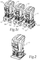
Figure 1c is a perspective view of the pumping assembly according to the invention in a third configuration; -
Figure 2 is a view of a portion of a pumping assembly according to the invention; -
Figure 3a is a view of a portion of a pumping assembly according to the configuration ofFigure 1a ; -
Figure 3b is a view of a portion of a pumping assembly according to the configuration ofFigure 1b ; -
Figure 3c is a view of a portion of a pumping assembly according to the configuration ofFigure 1c . - With reference to the figures, a pumping assembly according to the invention is generally designated
- by the
reference numeral 10, in a first configuration thereof, - by the
reference numeral 110, in a second configuration thereof, - by the
reference numeral 210, in a third configuration thereof. - The
pumping assembly base footing 13, and one or moreelectric pumps 12, each associated with afooting 13. - Each one of the
electric pumps 12 comprises: - a mechanical section, not shown in the figures, which comprises an intake port and a delivery port and contains one or more impellers which are interleaved by diffusers and are keyed on a driving shaft adapted to turn them,
- an electromechanical section, also not shown in the figures, which comprises an electric motor for the movement of the driving shaft.
- The
electric pumps 12 are of the vertical type. - The expression "vertical electric pump" in the present description is understood to mean that the
electric pump 11 has a vertical axis when in use, with the mechanical section below the electromechanical section. - The
pumping assembly manifolds - a
first delivery manifold 14a, - a
second intake manifold 14b. - The two
manifolds base assembly footing 13 that is present, and are connected fluidically, respectively: - the
first manifold 14a to the delivery port of theelectric pump 12, - the
second manifold 14b to the intake port of theelectric pump 12. - One of the particularities of the invention resides in that the pumping
assembly - These connection means are constituted by the
manifolds Figures 3a-3c , each manifold 14a, 14b has one ormore inlets - In particular:
- the
first manifold 14a is provided with one ormore inlets 15a, each for connection to the delivery port of a respectiveelectric pump 12, - the
second manifold 14b is provided with one ormore inlets 15b, each for connection to the intake port of a respectiveelectric pump 12. - Another particularity of the invention resides in that it is possible to obtain
pumping assemblies electric pump 12. - In particular, with the
electric pump 12 it is possible to obtain: - a pumping
assembly 10 with a singleelectric pump 12, as shown inFigure 1a , - a
pumping assembly 110 with twoelectric pumps 12, as shown inFigure 1b , - a
pumping assembly 210 with threeelectric pumps 12, as shown inFigure 1c . - In order to do this it is sufficient to use, depending on the requirements:
- a base 11 with a
single footing 13, as shown inFigure 3a , - a base 111 with two
footings 13, as shown inFigure 3b , - a base 211 with three
footings 13, as shown inFigure 3c , - In other embodiments, not shown in the figures, the pumping assembly according to the invention comprises a larger number of footings and electric pumps.
- Such a pumping
assembly base - It should be noted that with a pumping assembly according to the invention it is possible:
- to assemble the pumping
assembly base - to preassemble the pumping
assembly - A pumping assembly according to the invention also allows easy and quick management of stock and of order shipment, besides improving the utilization of the stock volumes or of the means of transport in which the
preassembled pumping assemblies bases - With the invention it is possible to assign an identification code to each individual
electric pump 12, to eachindividual base preassembled pumping assembly - The seller of the pumping assemblies can, therefore, depending on the demands of his customers, decide which
pumping assembly base electric pumps 12 to use for the installation. - This allows to reduce the time of logistics, making it easier both for the installation technician and for the manufacturer.
- In practice it has been found that the invention achieves the intended aim and objects, providing a pumping assembly which does not need to have individually preassembled electric pumps in stock, reducing the space occupations arising from said electric pumps and increasing the utilization of the available stock volume.
- The invention provides a pumping assembly in which the electric pumps can be assembled and connected quickly and easily at the installation site so as to form the pumping assembly.
- Moreover, the invention provides a pumping assembly which allows easier and quicker management of logistics with respect to similar pumping assemblies of the known type, in terms both of stock and shipping.
- Finally, the invention provides a pumping assembly which has a greater modularity and versatility of its components than similar pumping assemblies of the known type.
- The invention thus conceived is susceptible of numerous modifications and variations, all of which are within the scope of the appended claims; all the details may furthermore be replaced with other technically equivalent elements.
- In practice, the materials used, so long as they are compatible with the specific use, as well as the contingent shapes and dimensions, may be any according to the requirements and the state of the art.
- The disclosures in Italian Patent Application No.
102020000004912 - Where technical features mentioned in any claim are followed by reference signs, those reference signs have been included for the sole purpose of increasing the intelligibility of the claims and accordingly such reference signs do not have any limiting effect on the interpretation of each element identified by way of example by such reference signs.
Claims (9)
- A pumping assembly (10, 110, 210) comprising:- a base (11, 111, 211) provided with one or more footings (13),- one or more electric pumps (12), each associated with one of said one or more footings (13),- two manifolds (14a, 14b), said manifolds being a first delivery manifold (14a) and a second intake manifold (14b),said pumping assembly (10, 110, 210) being characterized in that it comprises means for fluidic connection between two or more of said electric pumps (12).
- The pumping assembly (10, 110, 210) according to claim 1, characterized in that said means for fluidic connection between two or more of said electric pumps (12) are constituted by said manifolds (14a, 14b).
- The pumping assembly (10, 110, 210) according to one or more of the preceding claims, characterized in that each one of said electric pumps (12) comprises:- a mechanical section, which comprises an intake port and a delivery port and contains one or more impellers which are interleaved by diffusers and are keyed on a driving shaft adapted to turn them,- an electromechanical section, which comprises an electric motor for the movement of said driving shaft.
- The pumping assembly (10, 110, 210) according to one or more of the preceding claims, characterized in that said one or more electric pumps (12) are of the vertical type.
- The pumping assembly (10, 110, 210) according to one or more of the preceding claims, characterized in that:- said first manifold (14a) has one or more inlets (15a), each for fluidic connection to the delivery port of one of said one or more electric pumps (12),- said second manifold (14b) is provided with one or more inlets (15b), each for fluidic connection to the intake port of one of said one or more electric pumps (12).
- A base (11, 111, 211) for a pumping assembly (10, 110, 210) according to one or more of the preceding claims, characterized in that it is provided with one or more footings (13) crossed by two manifolds (14a, 14b):- a first delivery manifold (14a),- a second intake manifold (14b).
- The base (11, 111, 211) according to claim 6, characterized in that:- said first manifold (14a) is provided with one or more inlets (15a), each for connection to a delivery port of a respective electric pump (12),- said second manifold (14b) is provided with one or more inlets (15b), each for connection to an intake port of a respective electric pump (12).
- An electric pump (12) for a pumping assembly (10, 110, 210) according to one or more of claims 1 to 6, characterized in that it comprises:- a mechanical section, which comprises an intake port and a delivery port and contains one or more impellers which are interleaved by diffusers and are keyed on a driving shaft adapted to turn them,- an electromechanical section, which comprises an electric motor for the movement of said driving shaft.
- The electric pump (12) according to claim 8, characterized in that it is of the vertical type.
Applications Claiming Priority (1)
| Application Number | Priority Date | Filing Date | Title |
|---|---|---|---|
| IT102020000004912A IT202000004912A1 (en) | 2020-03-09 | 2020-03-09 | PUMPING GROUP TO MANAGE THE PERFECTED LOGISTICS, ELECTRIC PUMP AND BASE FOR A SIMILAR PUMPING GROUP |
Publications (1)
| Publication Number | Publication Date |
|---|---|
| EP3879110A1 true EP3879110A1 (en) | 2021-09-15 |
Family
ID=70804932
Family Applications (1)
| Application Number | Title | Priority Date | Filing Date |
|---|---|---|---|
| EP21153805.3A Pending EP3879110A1 (en) | 2020-03-09 | 2021-01-27 | Pumping assembly with logistics management, electric pump and base for such a pumping assembly |
Country Status (2)
| Country | Link |
|---|---|
| EP (1) | EP3879110A1 (en) |
| IT (1) | IT202000004912A1 (en) |
Citations (3)
| Publication number | Priority date | Publication date | Assignee | Title |
|---|---|---|---|---|
| ITBO20100744A1 (en) * | 2010-12-20 | 2012-06-21 | Dgflow S R L | PUMPING GROUP |
| EP2775145A1 (en) * | 2013-03-08 | 2014-09-10 | Dab Pumps S.p.A. | Base for pumping devices |
| EP3171036A1 (en) * | 2015-11-19 | 2017-05-24 | Adwatec Oy | Liquid cooling station |
-
2020
- 2020-03-09 IT IT102020000004912A patent/IT202000004912A1/en unknown
-
2021
- 2021-01-27 EP EP21153805.3A patent/EP3879110A1/en active Pending
Patent Citations (3)
| Publication number | Priority date | Publication date | Assignee | Title |
|---|---|---|---|---|
| ITBO20100744A1 (en) * | 2010-12-20 | 2012-06-21 | Dgflow S R L | PUMPING GROUP |
| EP2775145A1 (en) * | 2013-03-08 | 2014-09-10 | Dab Pumps S.p.A. | Base for pumping devices |
| EP3171036A1 (en) * | 2015-11-19 | 2017-05-24 | Adwatec Oy | Liquid cooling station |
Also Published As
| Publication number | Publication date |
|---|---|
| IT202000004912A1 (en) | 2021-09-09 |
Similar Documents
| Publication | Publication Date | Title |
|---|---|---|
| EP1212534B1 (en) | Monodirectional impeller for centrifugal electric pumps having a permanent-magnet synchronous motor | |
| US5494403A (en) | Full-circumferential flow pump | |
| AU682393B2 (en) | Motor stator assembly and full-circumferential flow pump employing such motor stator assembly | |
| US12313082B2 (en) | Volute design for lower manufacturing cost and radial load reduction | |
| KR101646200B1 (en) | Apparatus for suction vane of axial and mixed flow pump | |
| EP3879110A1 (en) | Pumping assembly with logistics management, electric pump and base for such a pumping assembly | |
| AU2012201654A1 (en) | Centrifugal radial pumps and method for manufacturing thereof | |
| EP3771828A8 (en) | Multistage pump and subsea pumping arrangement | |
| US6790017B2 (en) | Integrated pump with serial-connected pump units arranged in parallel | |
| EP3149330B1 (en) | Integrated displacement controlled pump | |
| EP2037125B1 (en) | Self-priming centrifugal jet pump | |
| US11867190B2 (en) | Vertical electric pump having instruments for control and monitoring the operation of the pump accessible from a single side of the pump | |
| EP3362687B1 (en) | Pumps | |
| US20140134013A1 (en) | Immersion Pump and Method for Assembling an Immersion Pump | |
| US3126831A (en) | Motor-pump unit | |
| US2960937A (en) | Submersible pump | |
| JPH04103286U (en) | Suction stage of multistage circulation pump | |
| WO2007112398A2 (en) | Pump header body and modular manifold | |
| CA2938192C (en) | Horizontal pumping system with primary stage assembly and separate npsh stage assembly | |
| US20070280825A1 (en) | Turbine assembly | |
| EP1669589B1 (en) | An inline pump type fuel injection apparatus comprising a fuel flow path module | |
| US20220243739A1 (en) | Compact, high-efficiency air handling unit for residential hvac systems | |
| CN109667766B (en) | Detachable self-priming water pump assembly | |
| US20100284831A1 (en) | Adaptors for multistage pump assemblies | |
| EP3855020A1 (en) | Manifold for an electric pump and electric pump with such manifold |
Legal Events
| Date | Code | Title | Description |
|---|---|---|---|
| PUAI | Public reference made under article 153(3) epc to a published international application that has entered the european phase |
Free format text: ORIGINAL CODE: 0009012 |
|
| STAA | Information on the status of an ep patent application or granted ep patent |
Free format text: STATUS: THE APPLICATION HAS BEEN PUBLISHED |
|
| AK | Designated contracting states |
Kind code of ref document: A1 Designated state(s): AL AT BE BG CH CY CZ DE DK EE ES FI FR GB GR HR HU IE IS IT LI LT LU LV MC MK MT NL NO PL PT RO RS SE SI SK SM TR |
|
| STAA | Information on the status of an ep patent application or granted ep patent |
Free format text: STATUS: REQUEST FOR EXAMINATION WAS MADE |
|
| 17P | Request for examination filed |
Effective date: 20220301 |
|
| RBV | Designated contracting states (corrected) |
Designated state(s): AL AT BE BG CH CY CZ DE DK EE ES FI FR GB GR HR HU IE IS IT LI LT LU LV MC MK MT NL NO PL PT RO RS SE SI SK SM TR |
|
| STAA | Information on the status of an ep patent application or granted ep patent |
Free format text: STATUS: EXAMINATION IS IN PROGRESS |
|
| P01 | Opt-out of the competence of the unified patent court (upc) registered |
Effective date: 20230515 |
|
| 17Q | First examination report despatched |
Effective date: 20230619 |