EP3879104A1 - Hose pump - Google Patents
Hose pump Download PDFInfo
- Publication number
- EP3879104A1 EP3879104A1 EP21157044.5A EP21157044A EP3879104A1 EP 3879104 A1 EP3879104 A1 EP 3879104A1 EP 21157044 A EP21157044 A EP 21157044A EP 3879104 A1 EP3879104 A1 EP 3879104A1
- Authority
- EP
- European Patent Office
- Prior art keywords
- hose
- guide
- carrier disk
- rollers
- bed
- Prior art date
- Legal status (The legal status is an assumption and is not a legal conclusion. Google has not performed a legal analysis and makes no representation as to the accuracy of the status listed.)
- Granted
Links
- 239000012530 fluid Substances 0.000 claims abstract description 13
- 238000000034 method Methods 0.000 claims description 40
- 230000002572 peristaltic effect Effects 0.000 claims description 26
- 238000007373 indentation Methods 0.000 claims description 6
- 239000000463 material Substances 0.000 description 8
- 238000012544 monitoring process Methods 0.000 description 7
- 238000003780 insertion Methods 0.000 description 6
- 230000037431 insertion Effects 0.000 description 6
- 238000002347 injection Methods 0.000 description 5
- 239000007924 injection Substances 0.000 description 5
- 239000007788 liquid Substances 0.000 description 5
- 238000003825 pressing Methods 0.000 description 5
- 238000005086 pumping Methods 0.000 description 5
- 230000008878 coupling Effects 0.000 description 3
- 238000010168 coupling process Methods 0.000 description 3
- 238000005859 coupling reaction Methods 0.000 description 3
- 239000000203 mixture Substances 0.000 description 3
- 238000003860 storage Methods 0.000 description 3
- 238000011144 upstream manufacturing Methods 0.000 description 3
- 238000012546 transfer Methods 0.000 description 2
- 230000015572 biosynthetic process Effects 0.000 description 1
- 230000000903 blocking effect Effects 0.000 description 1
- 238000004140 cleaning Methods 0.000 description 1
- 230000001419 dependent effect Effects 0.000 description 1
- 238000013461 design Methods 0.000 description 1
- 238000001990 intravenous administration Methods 0.000 description 1
- 238000010253 intravenous injection Methods 0.000 description 1
- 239000004014 plasticizer Substances 0.000 description 1
- 238000005096 rolling process Methods 0.000 description 1
- 239000007787 solid Substances 0.000 description 1
- 230000001954 sterilising effect Effects 0.000 description 1
- 238000004659 sterilization and disinfection Methods 0.000 description 1
Images


Classifications
-
- F—MECHANICAL ENGINEERING; LIGHTING; HEATING; WEAPONS; BLASTING
- F04—POSITIVE - DISPLACEMENT MACHINES FOR LIQUIDS; PUMPS FOR LIQUIDS OR ELASTIC FLUIDS
- F04B—POSITIVE-DISPLACEMENT MACHINES FOR LIQUIDS; PUMPS
- F04B43/00—Machines, pumps, or pumping installations having flexible working members
- F04B43/12—Machines, pumps, or pumping installations having flexible working members having peristaltic action
- F04B43/1253—Machines, pumps, or pumping installations having flexible working members having peristaltic action by using two or more rollers as squeezing elements, the rollers moving on an arc of a circle during squeezing
-
- F—MECHANICAL ENGINEERING; LIGHTING; HEATING; WEAPONS; BLASTING
- F04—POSITIVE - DISPLACEMENT MACHINES FOR LIQUIDS; PUMPS FOR LIQUIDS OR ELASTIC FLUIDS
- F04B—POSITIVE-DISPLACEMENT MACHINES FOR LIQUIDS; PUMPS
- F04B43/00—Machines, pumps, or pumping installations having flexible working members
- F04B43/08—Machines, pumps, or pumping installations having flexible working members having tubular flexible members
-
- F—MECHANICAL ENGINEERING; LIGHTING; HEATING; WEAPONS; BLASTING
- F04—POSITIVE - DISPLACEMENT MACHINES FOR LIQUIDS; PUMPS FOR LIQUIDS OR ELASTIC FLUIDS
- F04B—POSITIVE-DISPLACEMENT MACHINES FOR LIQUIDS; PUMPS
- F04B43/00—Machines, pumps, or pumping installations having flexible working members
- F04B43/12—Machines, pumps, or pumping installations having flexible working members having peristaltic action
-
- F—MECHANICAL ENGINEERING; LIGHTING; HEATING; WEAPONS; BLASTING
- F04—POSITIVE - DISPLACEMENT MACHINES FOR LIQUIDS; PUMPS FOR LIQUIDS OR ELASTIC FLUIDS
- F04B—POSITIVE-DISPLACEMENT MACHINES FOR LIQUIDS; PUMPS
- F04B51/00—Testing machines, pumps, or pumping installations
-
- F—MECHANICAL ENGINEERING; LIGHTING; HEATING; WEAPONS; BLASTING
- F04—POSITIVE - DISPLACEMENT MACHINES FOR LIQUIDS; PUMPS FOR LIQUIDS OR ELASTIC FLUIDS
- F04B—POSITIVE-DISPLACEMENT MACHINES FOR LIQUIDS; PUMPS
- F04B53/00—Component parts, details or accessories not provided for in, or of interest apart from, groups F04B1/00 - F04B23/00 or F04B39/00 - F04B47/00
- F04B53/22—Arrangements for enabling ready assembly or disassembly
Definitions
- the invention relates to a hose pump according to the preamble of claim 1.
- Such peristaltic pumps are for example from the DE 20 2016 101 907 U1 and the EP 2 924 288 A2 known. These known peristaltic pumps have a hose bed into which a hose section of a hose bent in the shape of a loop can be inserted.
- the known peristaltic pumps furthermore comprise a counter bearing and a carrier disk which is rotatable relative to the counter bearing and on the upper side of which a plurality of squeezing rollers and a plurality of guide rollers are arranged.
- Both the squeezing rollers and the guide rollers in the radially outer region of the carrier disk and in the circumferential direction of the carrier disk are each arranged equidistant from one another, with a guide roller being arranged between two squeezing rollers following one another in the circumferential direction of the carrier disk.
- three squeeze rollers and three guide rollers are provided, each of which has an angular distance of 60 ° to the adjacent squeeze roller or guide roller in the circumferential direction of the carrier disk.
- the squeezing rollers have a smooth outer circumference and, with the carrier disk rotating in a conveying direction, press a hose inserted into the hose bed, squeezing the hose against the counter bearing, in order to transport a fluid located in the hose in the conveying direction.
- the cylindrical guide rollers have a circumferential guide groove on their outer circumference for receiving the radially inner tube half of the tube section and ensure exact positioning and guidance of the tube in the tube bed both when threading the tube section into the tube bed and during pumping operation.
- the downstream end of a hose section that is too long may slip out of the guide groove of the guide rollers and thereby lift off the support surface of the hose bed . This can lead to the hose section automatically and unintentionally unthreading itself during operation of the hose pump and becoming tangled in the process. This can block the peristaltic pump.
- the invention is based on the object of developing a hose pump of the generic type in such a way that hose sections of different pump hoses, in particular of different ones, can be reliably threaded in and out Pump hoses with a different material composition and with different material properties is made possible.
- a safe threading in and out of a hose section of the hose into the hose bed of the hose pump should also be ensured if the hose section should be a little too short or too long compared to the inner circumference of the counter bearing. Furthermore, it should be prevented that the inserted hose section does not automatically unthread during operation of the hose pump, especially under high pump pressures, and that the hose pump cannot become blocked if the hose is accidentally unthreaded during the threading process or during pump operation.
- the hose is first placed in a second guide plane, facing away from the carrier disk and formed by the guide cylinders of the guide rollers, and then the carrier disk is rotated in the conveying direction.
- the hose is brought from the second guide plane in the axial direction towards the carrier disk into the first guide plane defined by the guide grooves.
- the hose section initially inserted into the second guide level can be pushed downwards towards the surface of the carrier disk when threading in an area at the entrance of the hose bed either manually by an operator or by means of a mechanical hold-down device of the hose pump in order to ensure that at a rotation of the carrier disk, the inserted hose section is grasped by (at least) one guide roller and transferred from the upper, second guide plane down into the first guide plane.
- the guide groove running around the outer circumference of the guide rollers is preferably adapted to the shape of the hose and the guide groove can have an at least substantially semicircular cross-section, in particular for a hose with a circular cross-section. Due to the semicircular shape of the guide groove on the outer circumference of the guide rollers, they nestle against the surface of the hose when the hose pump is in operation, without squeezing it. This ensures that the hose is routed reliably and consistently in the hose bed when the hose pump is running.
- annular flange running around the outer circumference of the guide roller is preferably arranged between the guide groove and the guide cylinder arranged above the guide groove.
- This annular flange separates the guide groove from the guide cylinder of the respective guide roller and thereby defines the first guide plane facing the carrier disk in the region of the guide grooves and the second guide plane facing away from the carrier disk in the region of the guide cylinder Leadership roles.
- the second management level is axially offset from the first management level and is arranged above the first management level.
- an upper, second guide level facing away from the carrier disk enables when threading the hose that the operator of the hose pump can initially insert the hose section to be threaded into the upper, second guide level in a simple manner and without hindrance, the hose section inserted therein being initially guided.
- the guide cylinder around which the inserted hose section is placed exerts a pretension on the hose in its longitudinal direction, whereby the hose is stretched slightly, depending on its stretching properties.
- the carrier disk is then rotated in the conveying direction, a first guide roller gripping the tube section at an inlet of the tube bed.
- the carrier disk Due to the pretensioning of the hose, when the carrier disk is rotated, it is pulled from the upper, second guide level downwards onto the carrier disk into the lower, first guide level (with slight expansion of the hose) until the area of the inserted hose section at the entrance of the hose bed engages in the guide groove of the first guide roller. With further rotation of the carrier disk in the conveying direction, the inserted tube section is brought in this way over the entire circumference of the carrier disk from the upper, second guide level to the lower, first guide level, until the inserted tube section comes to rest neatly in the guide groove of all guide rollers and is therefore ready for use is inserted in the hose bed.
- the second guide level comprises a half-groove running around the outer circumference of the guide roller, because the inserted hose section can cling to the preferred half-groove shape of the second guide level.
- the semi-groove-shaped design of the second guide plane which in particular has a quarter-circle cross-section, also enables a simple and unimpeded insertion of a tube section to be threaded into the upper, second guide plane.
- the height of the guide cylinders of the guide rollers is preferably at least as large as the diameter of the hose for each guide roller. This also ensures good initial guidance of the hose in the second guide level when threading, because the hose is guided over its entire diameter by the guide cylinder.
- the squeezing rollers are preferably at least substantially cylindrical with a flat top, the guide cylinders of the guide rollers preferably lying in the axial direction above the top of the squeezing rollers. This prevents the inserted hose section from getting tangled when threading or during operation of the hose pump and thereby blocking the hose pump. Furthermore, this arrangement enables a hose section to be threaded into the hose bed to be inserted into the second guide plane without hindrance.
- the hose pump according to the invention is designed for operation with a single hose.
- a hose is inserted into the hose bed so that the squeezing rollers press the hose against the counter bearing while the carrier disk is rotating, in order to transport a fluid in the hose in the conveying direction.
- the annular flange is between the guide groove and the guide cylinder is arranged axially offset upwards away from the carrier disk in comparison to the annular flange of the other guide rollers.
- the guide groove of at least one or each guide roller has at least substantially a part-circular, in particular a semicircular, cross-section.
- the cross-section of the guide roller with the annular flange axially offset upward can also expediently deviate from a partially or semicircular cross-section in order to form an enlarged insertion cross-section in the area of the lower, first guide plane.
- the guide roller with an axially upwardly offset annular flange has an enlarged insertion cross-section in the area of the lower, first guide level due to the axial offset compared to the other guide rollers and therefore enables easier transfer of the hose from the upper, second guide level compared to the other guide rollers Management level to the lower, first management level.
- the other guide rollers when threading out the hose (which takes place by rotating the carrier disk counter to the conveying direction), ensure that the annular flange, which is axially offset slightly downwards towards the carrier disk, supports the hose section in the area of the outlet of the tube bed during the unwinding process and can thereby lift from the lower, first guide level to the upper, second guide level.
- an elevation is arranged at the outlet of the tube bed, which protrudes above the surface of the carrier disk, in order to support the ring flange of at least one of the guide rollers when threading out the tube while rotating the carrier disk counter to the conveying direction.
- a cover lying on the top of the guide rollers and covering the guide rollers is expediently provided.
- the cover is preferably designed in the shape of a cross or a star and in particular has indentations in the area between two adjacent guide rollers, which in particular can be convex or partially circular.
- the indentations are used for manual gripping of the cover, so that an operator can grasp the cover in an ergonomically optimized manner and manually set the carrier disk in rotation by exerting a torque on the cover and via the guide rollers attached to it.
- This enables a manual rotation of the carrier disk when threading in or threading out the hose, without having to use the motor of the pump for this purpose.
- the cover can also have bulges, which can in particular be convex or part-circular.
- openings can also be provided in the cover, into which an operator can insert one or more fingers to manually rotate the carrier disk (in the manner of a dial).
- the carrier disk is preferably connected to a shaft which is coupled to a motor and can be made to rotate by the latter.
- the guide rollers and the squeezing rollers are preferably rotatably mounted on the carrier disk in order to enable friction-free rolling on the surface of the hose. However, they can also each be connected to the carrier disk in a rotationally fixed manner.
- the axis of rotation of the carrier disk (axis of the shaft) and the axes of the Squeezing rollers and the guide rollers run parallel to one another. If the guide rollers and the squeezing rollers are rotatably mounted on the carrier disk, they can be set in rotation by the motor (if necessary via a gear). However, the guide rollers and the squeezing rollers can also be rotatably mounted on the carrier disk without coupling to a drive (passive).
- the guide rollers arranged rotatably on the carrier disk are actively set in rotation by the motor, a safe transfer of the hose from the upper, second guide level to the lower, first guide level can be achieved when threading, if at the same time the annular flange in the conveying direction helically towards the carrier disk is inclined downward.
- the hose section inserted into the second guide plane is brought from the upper, second guide plane to the lower, first guide plane through the downwardly coiled annular flange when the carrier disk is rotated and the guide rollers are simultaneously actively rotated in relation to the carrier disk.
- a guide roller is arranged between two squeezing rollers following one another in the circumferential direction on the carrier disk, with the squeezing rollers pressing a tube (or tube section) inserted into the tube bed while squeezing the tube against the counter bearing while the carrier disk is rotating in the conveying direction to transport fluid located in the hose in the conveying direction.
- the guide rollers are each set back in relation to the squeezing rollers following them in the conveying direction (direction of rotation of the carrier disk during pumping operation of the peristaltic pump), i.e. the angular distance ( ⁇ ) between a guide roller and the squeezing roller following in the conveying direction of this guide roller is smaller than the angular distance ( ⁇ ) between this guide roller and the squeezing roller preceding this guide roller in the conveying direction.
- This arrangement of the squeezing rollers and the guide rollers on the carrier disk prevents the upstream section of the hose when the hose is being threaded into the hose bed can slip out of the guide groove of a guide roller because the guide roller when the carrier disk rotates directly, ie at only a small angular distance ⁇ , is followed by a squeezing roller, which presses the upstream section of the hose against the counter bearing and thereby the position of the section of the already inserted into the hose bed Hose fixed in the hose bed.
- the preferred asymmetrical arrangement of the squeeze rollers and the guide rollers on the carrier disk prevents the hose from being unintentionally unraveled because each squeeze roller is immediately led by a guide roller when the carrier disk is rotated, i.e. at only a small angular distance ⁇ , which leads the downstream section of the Holds the hose securely in the hose bed even at high pumping pressures and prevents the downstream end of the hose from being able to bulge into a loop at the outlet of the hose bed, while the section of the hose that is a little further back in the conveying direction is pressed by the squeeze roller against the counter bearing.
- the amount of the relative angular difference ( ⁇ - ⁇ / ⁇ + ⁇ ) between the angular distance ⁇ between a guide roller and the squeezing roller preceding this guide roller in the conveying direction and the angular distance ⁇ between this guide roller and the squeezing roller following this guide roller in the conveying direction is preferably in the range of 0 , 2 to 0.5.
- the guide rollers and the squeezing rollers are expediently distributed rotationally symmetrically (with respect to the axis of rotation of the carrier disk as the center of symmetry) on the carrier disk, the symmetry angle being 360 ° / n if n is the number of guide rollers or the squeezing rollers.
- the hose pump according to the invention has three or more squeezing rollers and an equal number of guide rollers, which are arranged on the radially outer edge of the carrier disk in such a way that the angular distance ( ⁇ ) between each guide roller and the squeezing roller following in the conveying direction of a guide roller is less than 60 ° and in particular - with three guide rollers and three squeezing rollers - is preferably 45 °.
- the angular distance ( ⁇ ) between a guide roller and the squeezing roller preceding this guide roller in the conveying direction is correspondingly is greater than 60 ° and is in particular at least 75 °.
- the hose pump preferably comprises a device for monitoring the threading process when threading a hose into the hose bed.
- a device for monitoring the threading process that is particularly easy to implement comprises a device for detecting the torque acting on the carrier disk.
- a signal transmitter is preferably provided, which outputs a first signal when a torque threshold value is exceeded.
- the signal transmitter can also be set up in such a way that a second signal is output after a predetermined period of time has elapsed if the torque threshold value has not been reached or has not been exceeded within this period.
- the operator of the hose pump according to the invention expediently receives information about the state of the hose pump or the status of the threading process with each threading process.
- the status of the threading process determined by the device for monitoring the threading process can also be used to control an automatic threading routine, for example by automatically starting a further threading process after a failed threading process.
- the same preferably also applies to the threading out of the hose, in which case a successfully unthreaded hose is inferred if the torque falls below a threshold value.
- FIG 1 and Figure 2 is an embodiment of a hose pump according to the invention for conveying a fluid guided in a hose 16, in a perspective view ( Figure 1 , with inserted hose 16) or in a sectional view ( Figure 2 , with a sectional plane centered through a lower guide plane of the guide rollers).
- the peristaltic pump is used, for example, to convey an injection liquid for a medical, in particular an intravenous, injection, the injection liquid being carried out from a storage container into a patient hose connected to the patient, in particular intravenously.
- the hose pump is arranged in a pump housing 14 on which a housing cover, not shown here for reasons of clarity, is attached is articulated pivotably by means of a fastening device 18.
- a hold-down device is expediently formed on the housing cover.
- the pump housing 14 contains a cassette holder 13 designed as a recess in the housing ( Figure 2 ) for inserting an exchangeable cassette 15 ( Figure 1 ).
- the partially shown cassette 15 comprises a cassette housing 15a in which a guide channel 15b is formed.
- the guide channel 15b serves to guide a fluid to be conveyed with the hose pump.
- a loop-shaped or curved section of the tube 16 protrudes from the cassette housing 15a.
- the cassette 15 is connected to a plurality of connecting hoses which can be connected to storage containers for liquids (for example, injection liquids).
- a connector 15c is arranged on the side of the cassette housing 15a, to which, for example, a patient hose can be connected in order to connect it to the hose 16.
- the peristaltic pump further comprises a hose bed 2 with a hose inlet 2a and a hose outlet 2b, as well as a counter bearing 4.
- the counter bearing 4 is formed by the inner circumference of a segment of a circle, which is open in the area of the hose inlet 2a and the hose outlet 2b of the hose bed 2 for the introduction of a hose 16 is.
- the hose bed 2 is used to receive a hose section of a pump hose (the hose section is also generally referred to below as hose 16), a fluid (for example an injection liquid for intravenous injection into the bloodstream of a patient) being guided in the hose.
- a tube 16 inserted into the tube bed 2 rests on a guide surface formed by the surface of the carrier disk 1.
- the counter bearing 4 tapers outwards tangentially, as can be seen from the figures.
- squeezing rollers 3 On the surface of the carrier disk 1, in the radially outer section (near its outer circumference), several squeezing rollers 3 are rotatably mounted about an axis perpendicular to the carrier disk 1.
- the axes of the squeezing rollers 3 lie on a circular path running concentrically to the central axis of rotation of the carrier disk 1 (dashed line in Figure 2 ).
- three such squeezing rollers 3 a, 3 b, 3 c are provided and are evenly distributed over the circumference of the carrier disk 1. If in the following reference is made to the squeezing rollers 3a, 3b, 3c, each of which is configured identically, this is done with the reference symbol 3.
- a guide roller 5 is arranged on the carrier disk 1 between adjacent squeezing rollers 3.
- three such guide rollers 5a, 5b, 5c are provided and distributed evenly over the circumference of the carrier disk 1 (or on the dashed circular path). If in the following reference is made to the at least essentially identically designed guide rollers 5a, 5b, 5c, this is done with the reference number 5.
- the guide rollers 5 are rotatably mounted on the carrier disk 1, the axes of the guide rollers 5 as well as the axes of the squeezing rollers 3, run parallel to the drive shaft 10 and also on the circular path (dashed circle in Figure 2 ) lie.
- the squeezing rollers 3 and the guide rollers 5 can either be freely rotatably mounted on the carrier disk 1 or they can be coupled to the drive of the hose pump via a coupling. If the squeezing rollers 3 and / or the guide rollers 5 are coupled to the drive via a coupling, they are set in rotation by the drive in opposite directions to the carrier disk 1 when the drive is running.
- the squeezing rollers 3a, 3b, 3c and the guide rollers 5a, 5b, 5c are arranged on the radially outer edge of the carrier disk 1 in such a way that the angular distance ⁇ between each guide roller and the squeezing roller following in the conveying direction of a guide roller is less than 60 ° and - like in the illustrated embodiment of the Figures 1 and 2 - in particular is 45 °.
- the angular distance ⁇ between a guide roller and the squeezing roller preceding this guide roller in the conveying direction is greater than 60 ° and is 75 ° in the exemplary embodiment shown.
- This preferred arrangement of the pinch and guide rollers is in the EP 3 232 059 A2 which is referred to in this regard.
- the guide rollers 5 essentially have a cylindrical basic shape and, on their outer circumference (on the cylinder jacket), have a guide groove 25 running around the circumference.
- the guide grooves 25 of the guide rollers 5 form a first guide plane 25 in which a hose 16 inserted into the hose bed 2 is guided through the guide rollers 5 during operation of the hose pump, the carrier disk 1 being set in rotation by the drive when the pump is running and the The hose 16 engages in the guide grooves 25 of the guide rollers 5 and is thereby held on the guide surface of the hose bed 2.
- each guide roller 5 has a guide cylinder 26, as shown in FIG Figure 3 evident.
- the guide cylinder 26 of each guide roller 5 faces away from the carrier disk 1 and the guide cylinders 26 of the guide rollers 5 form an upper, second guide plane B, which is arranged offset axially upwards from the first guide plane A (i.e. pointing away from the carrier disk 1).
- the second guide plane B is separated from the first guide plane A by an annular flange 20 running around the outer circumference of each guide roller 5.
- the underside of the annular flange 20 forms the upper section of the guide groove 25 for each guide roller 5 and the upper side of the annular flange 20 merges into a semi-groove 21 which is approximately quarter-circular in cross section and which is part of the second guide plane B.
- the height of the guide cylinder 26 of the guide rollers 5 depends on the diameter of the tube to be inserted into the tube bed Hose 16 adapted and corresponds at least to the hose diameter.
- the height of the guide cylinder 26 is preferably (somewhat) greater than the hose diameter.
- the second guide plane B which is formed by the guide cylinders 26 of the guide rollers 5 and the annular flange 20, lies above the flat top side 23 of the squeezing rollers 3, as can be seen from the side view of FIG Figure 4 evident.
- a cover 22 connecting and covering the guide rollers 5 is arranged (the cover 22 is shown in FIG Figure 2 omitted).
- the cover 22 is designed in a star shape here and has a central opening and several convex indentations 27.
- one of the guide rollers 5 (here the guide roller 5a) has the annular flange 20 between the guide groove 25 and the guide cylinder 26 arranged above it, compared to the annular flange 20 of the other guide rollers (here the guide rollers 5b and 5c ) arranged axially offset away from the carrier disk 1 upwards.
- This guide roller 5a with axially upwardly offset annular flange 20 thus has a slightly modified cross-sectional shape of the guide groove 25 compared to the other guide rollers (5b and 5c) with a slightly enlarged cross-section in the upper section.
- the cross-sectional shape of the guide groove 25 of the guide roller 5a with the annular flange 20 offset axially upward therefore deviates somewhat from the shape of a semicircular groove, as from Figure 4 evident.
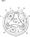
- the section of the pump hose 16 protruding from the cassette housing 15a is threaded into the hose bed 2, as follows with reference to FIG Figures 5 to 8 explained: First, an operator inserts a cassette 15 into the receptacle 13 provided for this on the pump housing 14. After the cassette 15 has been inserted into the receptacle 13 provided for it, the portion of the hose 16 protruding from the cassette housing 15a is manually placed around the guide cylinder 26 of the guide rollers 5 by the operator, as in FIG Figure 5 shown. The tube 16 is then located in the second guide plane B defined by the guide cylinder 26 of the guide rollers 25.
- the length of the section of the tube 16 protruding from the cassette housing 15a is based on the geometry of the Hose pump adapted so that when the hose 16 is placed around the guide cylinder 26 of the guide rollers 5, the hose 16 is brought under a slight pretension and is thereby slightly stretched in its longitudinal direction.
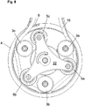
- the area of the hose 16, which is located at the hose inlet 2a of the hose bed 2 is pressed down in the direction of the carrier disk 1. This can be done manually by the operator with a finger, as in Figure 6 indicated.
- the pressing down of the hose 16 in the area of the hose inlet 2a of the hose bed 2 can, however, also take place in an automated manner by means of a mechanical hold-down device.
- the mechanical hold-down device can be, for example, a lever that is movably arranged on the pump housing 14.
- the carrier disk 1 is rotated in the conveying direction (clockwise in the exemplary embodiment shown). This rotation can either be done manually by the operator or automatically by the drive of the hose pump, which is coupled to the carrier disk 1.
- the operator can exert a torque on the carrier disk 1 with one hand via the cover 22.
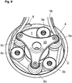
- the carrier disk 1 is rotated (either manually by the operator or automatically by the drive of the hose pump) in the conveying direction until the hose 16 engages in the guide groove 25 of a guide roller 5 (in Figure 7 this is the guide groove 5c).
- the hose 16 By pressing down the hose 16 in the area of the hose inlet 2a of the hose bed 2, the hose 16 is brought into the lower, first guide plane A in this area, in which the guide grooves 25 of the guide rollers 5 are located.
- the guide rollers 5 passes the hose inlet 2a as a result of the rotation of the carrier disk 1 in the conveying direction (here the guide groove 5c, as in FIG Figure 7 shown)
- the section of the hose 16 located in the lower, first guide plane A will therefore engage in the guide groove 25 of the relevant guide roller (here: the guide roller 5c).
- the hose 16 is located completely in the lower, first guide plane A, as in FIG Figure 8 shown, and is thereby completely inserted in the tube bed 2.
- the hose pump is now ready for operation to deliver a fluid located in the hose 16.
- the pump can be operated in its conveying direction F to convey the fluid in the hose.
- the carrier disk 1 in the embodiment shown in the drawing is set in rotation by the drive in the conveying direction (here: clockwise), whereby the squeezing rollers 3 press the hose intermittently with squeezing against the counter bearing 4 and thereby transport the fluid in the hose in the conveying direction .
- the guide rollers 5 provide a secure and constant positioning of the section of the hose 16 in the hose bed 2 securely in that the hose engages in the guide grooves 25 of the guide rollers 5 and is thereby guided.
- the tube 16 When the tube 16 has been properly threaded into the tube bed 2, it is guided through the guide groove 25 of the guide rollers 5 and runs at a small distance and essentially parallel to the surface of the carrier disk 1 and between the outer circumference of the squeezing rollers 3 and the counter bearing 4.
- the (radial) distance between the outer circumference of the squeezing rollers 3 is selected to be smaller than the diameter of the tube 16, so that the tube is clamped between the outer circumference of the squeezing rollers 3 and the counter bearing 4, squeezing the flexible tube.
- the carrier disk 1 is rotated further in the conveying direction until the following guide roller on the carrier disk 1 in the conveying direction (in Figure 7 the guide roller 5b) passes the hose inlet 2a. This can be repeated until the hose 16 engages in a guide groove 25 of one of the guide rollers 5.
- the guide roller 5a has an annular flange 20 which is arranged offset upwards and thus an enlarged insertion cross section in the area of its guide groove 25.
- the enlarged insertion cross-section of the guide roller 5a ensures that the section of the hose 16 that is pressed down in the area of the hose inlet 2a is always grasped by the guide groove 25 of this guide roller 5a and thereby from the upper, second guide plane B to the lower, first Management level A is drawn.
- a corresponding device is expediently provided in the hose pump to monitor the threading process.
- This device for monitoring the threading process can for example comprise a device for detecting the torque acting on the carrier disk 1.
- the rotational resistance of the carrier disk 1 increases, which is why the drive of the hose pump must apply a higher torque to further rotate the carrier disk 1 (at the same rotational speed).
- a signal transmitter outputs a signal which indicates to the operator that the hose 16 has been properly inserted into the hose bed 2.
- the signal transmitter emits a second signal after a specified period of time if the specified torque threshold value is not reached or has not been exceeded within this period is.
- the operator receives the information that the threading process was not successful. In this case, the operator can insert another cassette 15 into the receptacle 13 provided for this purpose on the hose pump and start a new threading process.
- a blockage of the hose pump occurs during a threading process, for example due to the hose 16 becoming tangled, this is also detected via the device for monitoring the threading process and the signal transmitter can output a corresponding signal.
- the threading process is blocked and the operator is requested to insert a new cassette 15.
- the signals can be output, for example, in the form of an acoustic signal or in the form of an indication on a display.
- the hose 16 can be unthreaded from the hose bed 2 via an automatic unthreading routine.
- the carrier disk 1 is rotated by the drive of the peristaltic pump against the conveying direction (that is to say in the counter-clockwise direction in the exemplary embodiment shown).
- the hose arranged at the hose outlet 2b of the hose bed 2 is removed Figure 9 visible survey 8 used. The elevation 8 protrudes above the surface of the carrier disk 1 and lifts the tube 16 somewhat from the surface of the carrier disk 1 in the region of the tube outlet 2a.
- the hose 16 With further rotation of the carrier disk 1 against the conveying direction, the hose 16 is raised over the entire circumference of the hose bed 2 from the lower, first guide level A into the upper, second guide level B, until after a complete rotation of the carrier disk 1 (by 360 °) in the conveying direction, the hose 16 is located completely and over the entire circumference of the hose bed 2 in the upper, second guide level B (corresponding to the in Figure 5 position shown). In this position, the hose 16 can be pulled upwards from the guide rollers 5 by the operator and removed from the hose pump together with the cassette 15.
- this distance between the guiding or squeezing rollers is 90 °.
- the angular distance between the Squeezing rollers 3 and the guide rollers 5 can expediently be different, as described above, or they can also be equidistant.
- a central cylinder projecting above the surface of the carrier disk 1 can be arranged in the center of the carrier disk 1 coaxially to its axis of rotation, which cylinder surrounds the drive shaft 10 and its outer diameter at least approximately to the outer circumference of the radially further outward squeezing rollers and leadership roles is enough.
- the central cylinder can be designed as a hollow cylinder or also as a solid cylinder and is expediently connected to the carrier disk 1 in a rotationally fixed manner.
- the central cylinder When threading the hose, the central cylinder prevents it from coming to rest on the radially inward-facing side of the guide rollers 5 and therefore cannot be properly threaded into the hose bed 2 between the outer circumference of the squeezing rollers 3 and the counter bearing 4.
- the radial distance between the outer surface of the cylinder and the outer circumference of the guide rollers should be smaller than the diameter of the hose to be inserted into the hose bed.
- the height of the central cylinder (in the axial direction) is expediently adapted to the height of the guide rollers and has at least the same height as the guide rollers.
Abstract
Die Erfindung betrifft eine Schlauchpumpe zur Förderung eines in einem Schlauch geführten Fluids, mit einem ein Gegenlager (4) aufweisendes Schlauchbett (2) zur Aufnahme des Schlauchs, einer relativ zum Gegenlager (2) drehbaren Trägerscheibe (1), einer Mehrzahl von in Umfangsrichtung auf der Trägerscheibe (1) angeordneten Quetschrollen (3) und einer Mehrzahl von in Umfangsrichtung auf der Trägerscheibe (1) angeordneten Führungsrollen (5) mit einer an ihrem Außenumfang in Umfangsrichtung umlaufenden Führungsnut (25), welche eine der Trägerscheibe (1) zugewandte erste Führungsebene (A) ausbildet. Um ein zuverlässiges Ein- und Ausfädeln von verschiedenen Schläuchen mit unterschiedlichen Eigenschaften in das Schlauchbett bzw. aus dem Schlauchbett gewährleisten zu können, weist jede Führungsrolle (5) oberhalb der Führungsnut (25) einen Führungszylinder (26) zur Führung des Schlauchs beim Einfädeln in das Schlauchbett (2) und/oder beim Ausfädeln aus dem Schlauchbett (2) auf.The invention relates to a hose pump for conveying a fluid guided in a hose, with a hose bed (2) having a counter bearing (4) for receiving the hose, a carrier disk (1) rotatable relative to the counter bearing (2) and a plurality of circumferential supports the carrier disk (1) arranged squeezing rollers (3) and a plurality of guide rollers (5) arranged in the circumferential direction on the carrier disk (1) with a guide groove (25) running around the outer circumference in the circumferential direction, which has a first guide plane facing the carrier disk (1) (A) trains. In order to be able to ensure reliable threading in and out of different hoses with different properties in the hose bed or out of the hose bed, each guide roller (5) has a guide cylinder (26) above the guide groove (25) for guiding the hose during threading into the Hose bed (2) and / or when threading out of the hose bed (2).
Description
Die Erfindung betrifft eine Schlauchpumpe nach dem Oberbegriff des Anspruchs 1.The invention relates to a hose pump according to the preamble of
Derartige Schlauchpumpen sind beispielsweise aus der
Zum automatisierten Ein- und Ausfädeln des Schlauchabschnitts in das Schlauchbett kann eine motorisch betriebene Einrichtung mit einer Schneckenspindel verwendet werden, wie sie bspw. in der
Weiterhin hat sich gezeigt, dass die beschriebenen Probleme beim Einfädeln des Schlauchs auch sehr stark von den mechanischen Eigenschaften des Schlauchs, insbesondere von dessen Dehnbarkeit und Reibungseigenschaften, abhängen. Dabei hängen die mechanischen Eigenschaften des Schlauchs von vielen unterschiedlichen Faktoren ab, wie z.B. der Materialzusammensetzung, dem Alter und der Vorbehandlung des Schlauchs, bspw. durch Reinigung und Sterilisation. Die Materialeigenschaften des Schlauchs können sich auch im Laufe der Zeit bei einer Lagerung, bspw. durch Austritt von Materialkomponenten, insbesondere der in der Kunststoffkomposition enthaltenen Weichmachern, ändern. Das Verhalten eines Schlauchs beim Ein- und Ausfädeln kann daher sehr unterschiedlich ausfallen, was ein korrektes Ein- und Ausfädeln von unterschiedlichen Schläuchen erheblich erschwert.Furthermore, it has been shown that the problems described when threading the hose are also very much dependent on the mechanical properties of the hose, in particular on its extensibility and friction properties. The mechanical properties of the hose depend on many different factors, such as the material composition, the age and the pretreatment of the hose, e.g. through cleaning and sterilization. The material properties of the hose can also change in the course of time during storage, for example due to the escape of material components, in particular the plasticizers contained in the plastic composition. The behavior of a hose when threading in and out can therefore be very different, which makes correct threading in and out of different hoses considerably more difficult.
Hiervon ausgehend liegt der Erfindung die Aufgabe zugrunde, eine gattungsgemäße Schlauchpumpe so weiter zu bilden, dass ein zuverlässiges Ein- und Ausfädeln von Schlauchabschnitten verschiedener Pumpenschläuche, insbesondere von verschiedenen Pumpenschläuchen mit einer unterschiedlichen Materialzusammensetzung und mit unterschiedlichen Materialeigenschaften, ermöglicht wird.Proceeding from this, the invention is based on the object of developing a hose pump of the generic type in such a way that hose sections of different pump hoses, in particular of different ones, can be reliably threaded in and out Pump hoses with a different material composition and with different material properties is made possible.
Dabei soll insbesondere auch dann ein sicheres Ein- und Ausfädeln eines Schlauchabschnitts des Schlauchs in das Schlauchbett der Schlauchpumpe sichergestellt werden, wenn der Schlauchabschnitt im Vergleich zum Innenumfang des Gegenlagers etwas zu kurz oder zu lang sein sollte. Weiterhin soll verhindert werden, dass sich während des Betrieb der Schlauchpumpe, insbesondere unter hohen Pumpdrücken, der eingelegte Schlauchabschnitt nicht selbsttätig ausfädelt und dass es bei einem versehentlichen Ausfädeln des Schlauchs beim Einfädelvorgang oder während des Pumpenbetriebs nicht zu einer Blockade der Schlauchpumpe kommen kann.In particular, a safe threading in and out of a hose section of the hose into the hose bed of the hose pump should also be ensured if the hose section should be a little too short or too long compared to the inner circumference of the counter bearing. Furthermore, it should be prevented that the inserted hose section does not automatically unthread during operation of the hose pump, especially under high pump pressures, and that the hose pump cannot become blocked if the hose is accidentally unthreaded during the threading process or during pump operation.
Diese Aufgaben werden mit einer Schlauchpumpe mit den Merkmalen des Anspruchs 1 sowie mit dem Verfahren des Anspruchs 13 gelöst. Bevorzugte Ausführungsformen der Schlauchpumpe und des Verfahrens sind den Unteransprüchen zu entnehmen.These objects are achieved with a hose pump with the features of
Die erfindungsgemäße Schlauchpumpe verfügt über ein Schlauchbett zum Einlegen eines Schlauchabschnitts eines Pumpschlauchs, ein Gegenlager, eine relativ zum Gegenlager drehbare Trägerscheibe, eine Mehrzahl von in Umfangsrichtung auf der Trägerscheibe bevorzugt äquidistant zueinander angeordnete Quetschrollen und eine Mehrzahl von in Umfangsrichtung auf der Trägerscheibe bevorzugt äquidistant zueinander angeordnete Führungsrollen mit einer an ihrem Außenumfang in Umfangsrichtung umlaufenden Führungsnut, welche eine der Trägerscheibe zugewandte erste Führungsebene ausbildet. Erfindungsgemäß weist jede Führungsrolle oberhalb der Führungsnut einen von der Trägerscheibe abgewandten Führungszylinder zur anfänglichen Führung des Schlauchs beim Einfädeln in das Schlauchbett und/oder beim Ausfädeln aus dem Schlauchbett auf.The hose pump according to the invention has a hose bed for inserting a hose section of a pump hose, a counter-bearing, a carrier disk rotatable relative to the counter-bearing, a plurality of squeezing rollers, preferably arranged equidistantly from one another in the circumferential direction, and a plurality of squeezing rollers preferably arranged equidistantly from one another in the circumferential direction on the carrier disk Guide rollers with a guide groove running around their outer circumference in the circumferential direction, which forms a first guide plane facing the carrier disk. According to the invention, each guide roller above the guide groove has a guide cylinder facing away from the carrier disk for initially guiding the hose when threading into the hose bed and / or when threading it out of the hose bed.
Der Führungszylinder der Führungsrollen dient dabei beim Einfädeln des Schlauchs in das Schlauchbett zur anfänglichen Führung des Schlauchs und ermöglicht bei einer Drehung der Trägerscheibe in einer Förderrichtung eine sichere Anfangsführung des Schlauchs und eine sichere Einführung des Schlauchs in die Führungsnuten der Führungsrollen, die der Trägerscheibe zugewandt sind und während des Betriebs der Schlauchpumpe bei sich in einer Förderrichtung drehender Trägerscheibe eine positionsgenaue Führung des Schlauchs in dem Schlauchbett sicher stellen.When threading the hose into the hose bed, the guide cylinder of the guide rollers is used to initially guide the hose and, when the carrier disk is rotated in a conveying direction, enables safe initial guidance of the hose and safe introduction of the hose into the guide grooves of the guide rollers that face the carrier disk and during the operation of the hose pump, with the carrier disk rotating in a conveying direction, ensure that the hose is guided in the hose bed in an exact position.
Zum Einfädeln des Schlauchs in das Schlauchbett der Schlauchpumpe wird der Schlauch zunächst in eine von der Trägerscheibe abgewandte, von den Führungszylindern der Führungsrollen gebildete zweite Führungsebene eingelegt und danach wird die Trägerscheibe in Förderrichtung gedreht. Dabei wird der Schlauch von der zweiten Führungsebene in axialer Richtung auf die Trägerscheibe hin in die von den Führungsnuten definierte erste Führungsebene gebracht. Dabei kann der anfänglich in die zweite Führungsebene eingelegte Schlauchabschnitt beim Einfädeln in einem Bereich am Eingang des Schlauchbetts entweder manuell durch einen Bediener oder mittels eines mechanischen Niederhalters der Schlauchpumpe nach unten in Richtung auf die Oberfläche der Trägerscheibe gedrückt werden, um sicher zu stellen, dass bei einer Drehung der Trägerscheibe der eingelegte Schlauchabschnitt von (wenigstens) einer Führungsrolle erfasst und von der oberen zweiten Führungsebene nach unten in die erste Führungsebene überführt wird.To thread the hose into the hose bed of the hose pump, the hose is first placed in a second guide plane, facing away from the carrier disk and formed by the guide cylinders of the guide rollers, and then the carrier disk is rotated in the conveying direction. The hose is brought from the second guide plane in the axial direction towards the carrier disk into the first guide plane defined by the guide grooves. The hose section initially inserted into the second guide level can be pushed downwards towards the surface of the carrier disk when threading in an area at the entrance of the hose bed either manually by an operator or by means of a mechanical hold-down device of the hose pump in order to ensure that at a rotation of the carrier disk, the inserted hose section is grasped by (at least) one guide roller and transferred from the upper, second guide plane down into the first guide plane.
Die Quetschrollen der erfindungsgemäßen Schlauchpumpe sind zweckmäßig zumindest im Wesentlichen zylindrisch und mit einer glatten Mantelfläche ausgebildet, wobei der Außenumfang der zylindrischen Quetschrollen den Schlauch gegen das Gegenlager presst, um ein sich im Schlauch befindliches Fluid in Förderrichtung zu transportieren.The squeezing rollers of the hose pump according to the invention are expediently at least substantially cylindrical and have a smooth outer surface, the outer circumference of the cylindrical squeezing rollers pressing the hose against the counter bearing in order to transport a fluid in the hose in the conveying direction.
Die am Außenumfang der Führungsrollen umlaufende Führungsnut ist bevorzugt der Form des Schlauchs angepasst und die Führungsnut kann insbesondere für einen Schlauch mit kreisförmigem Querschnitt einen zumindest im Wesentlichen halbkreisförmig ausgebildeten Querschnitt aufweisen. Aufgrund der halbkreisförmigen Ausformung der Führungsnut am Außenumfang der Führungsrollen schmiegen sich diese im Betrieb der Schlauchpumpe an die Oberfläche des Schlauchs an, ohne diesen zu quetschen. Dadurch wird bei laufender Schlauchpumpe eine sichere und gleichbleibende Führung des Schlauchs im Schlauchbett gewährleistet.The guide groove running around the outer circumference of the guide rollers is preferably adapted to the shape of the hose and the guide groove can have an at least substantially semicircular cross-section, in particular for a hose with a circular cross-section. Due to the semicircular shape of the guide groove on the outer circumference of the guide rollers, they nestle against the surface of the hose when the hose pump is in operation, without squeezing it. This ensures that the hose is routed reliably and consistently in the hose bed when the hose pump is running.
Bevorzugt ist bei jeder Führungsrolle zwischen der Führungsnut und dem oberhalb der Führungsnut angeordneten Führungszylinder ein am Außenumfang der Führungsrolle umlaufender Ringflansch angeordnet. Dieser Ringflansch trennt die Führungsnut von dem Führungszylinder der jeweiligen Führungsrolle ab und definiert dadurch die der Trägerscheibe zugewandte erste Führungsebene im Bereich der Führungsnuten und die der Trägerscheibe abgewandte zweite Führungsebene im Bereich der Führungszylinder der Führungsrollen. Die zweite Führungsebene ist dabei axial zur ersten Führungsebene versetzt und oberhalb der ersten Führungsebene angeordnet. Wenn hier von oben bzw. oberhalb gesprochen wird ist dabei eine in Bezug auf die Oberfläche der Trägerscheibe, welche für einen in das Schlauchbett eingelegten Schlauch eine Führungsfläche ausbildet, senkrecht stehende Richtung gemeint. Dabei ist keine Beschränkung in Bezug auf die Orientierung der Schlauchpumpe gegeben, denn diese kann sowohl in einer horizontalen als auch in einer vertikalen Lage der Trägerscheibe betrieben werden.In each guide roller, an annular flange running around the outer circumference of the guide roller is preferably arranged between the guide groove and the guide cylinder arranged above the guide groove. This annular flange separates the guide groove from the guide cylinder of the respective guide roller and thereby defines the first guide plane facing the carrier disk in the region of the guide grooves and the second guide plane facing away from the carrier disk in the region of the guide cylinder Leadership roles. The second management level is axially offset from the first management level and is arranged above the first management level. When speaking of above or above, a direction that is perpendicular to the surface of the carrier disk, which forms a guide surface for a tube inserted into the tube bed, is meant. There is no restriction with regard to the orientation of the hose pump, because this can be operated both in a horizontal and in a vertical position of the carrier disk.
Die Ausbildung einer oberen, der Trägerscheibe abgewandten zweiten Führungsebene ermöglicht beim Einfädeln des Schlauchs, dass der Bediener der Schlauchpumpe den einzufädelnden Schlauchabschnitt zunächst auf einfache Weise und behinderungsfrei in die obere, zweite Führungsebene einlegen kann, wobei der darin eingelegte Schlauchabschnitt eine anfängliche Führung erfährt. Dabei wird durch die Führungszylinder, um die der eingelegte Schlauchabschnitt gelegt wird, eine Vorspannung auf den Schlauch in seine Längsrichtung ausgeübt, wodurch der Schlauch, je nach Dehnungseigenschaften, geringfügig gedehnt wird. Zum Einfädeln des eingelegten Schlauchabschnitts in das Schlauchbett wird die Trägerscheibe danach in Förderrichtung gedreht, wobei eine erste Führungsrolle den Schlauchabschnitt an einem Eingang des Schlauchbetts ergreift. Aufgrund der Vorspannung des Schlauchs wird dieser bei einer Drehung der Trägerscheibe von der oberen, zweiten Führungsebene nach unten auf die Trägerscheibe hin in die untere, erste Führungsebene gezogen (unter leichter Dehnung des Schlauchs), bis der am Eingang des Schlauchbetts liegende Bereich des eingelegten Schlauchabschnitts in die Führungsnut der ersten Führungsrolle eingreift. Bei weiterer Drehung der Trägerscheibe in Förderrichtung wird der eingelegte Schlauchabschnitt auf diese Weise über den gesamten Umfang der Trägerscheibe von der oberen, zweiten Führungsebene in die untere, erste Führungsebene gebracht, bis der eingelegte Schlauchabschnitt sauber in der Führungsnut aller Führungsrollen zu liegen kommt und dadurch betriebsbereit im Schlauchbett eingelegt ist.The formation of an upper, second guide level facing away from the carrier disk enables when threading the hose that the operator of the hose pump can initially insert the hose section to be threaded into the upper, second guide level in a simple manner and without hindrance, the hose section inserted therein being initially guided. The guide cylinder around which the inserted hose section is placed exerts a pretension on the hose in its longitudinal direction, whereby the hose is stretched slightly, depending on its stretching properties. In order to thread the inserted tube section into the tube bed, the carrier disk is then rotated in the conveying direction, a first guide roller gripping the tube section at an inlet of the tube bed. Due to the pretensioning of the hose, when the carrier disk is rotated, it is pulled from the upper, second guide level downwards onto the carrier disk into the lower, first guide level (with slight expansion of the hose) until the area of the inserted hose section at the entrance of the hose bed engages in the guide groove of the first guide roller. With further rotation of the carrier disk in the conveying direction, the inserted tube section is brought in this way over the entire circumference of the carrier disk from the upper, second guide level to the lower, first guide level, until the inserted tube section comes to rest neatly in the guide groove of all guide rollers and is therefore ready for use is inserted in the hose bed.
Durch die von den Führungszylindern der Führungsrollen auf den eingelegten Schlauchabschnitt ausgeübte Vorspannung wird dabei gewährleistet, dass der Schlauch beim Einfädeln möglichst wenig Kontakt mit dem Gegenlager hat. Dadurch wird verhindert, dass der Schlauch am Gegenlager reibt und dass die unterschiedlichen Reibeigenschaften von verschiedenen Schläuchen einen (negativen) Einfluss auf das Einfädeln des Schlauchs ausüben können. Der Einfädelvorgang wird dadurch weitgehend unabhängig von den mechanischen Eigenschaften des Schlauchs. Damit wird ein immer gleiches und Sicheres Einfädeln von verschiedenen Schläuchen mit ggf. unterschiedlichen Materialparametern sowie ein materialschonendes Einfädeln des Schlauchs ermöglicht.The pre-tension exerted on the inserted hose section by the guide cylinders of the guide rollers ensures that the hose has as little contact as possible with the counter-bearing when it is threaded in. This prevents the hose from rubbing against the counter bearing and prevents the different friction properties of different hoses from having a (negative) influence on the threading of the hose. The threading process is largely independent of the mechanical properties of the hose. This enables the same and reliable threading of different hoses, possibly with different material parameters, as well as threading of the hose that is gentle on the material.
Eine beim Einfädeln besonders sichere Anfangsführung des Schlauchs wird erzielt, wenn die zweite Führungsebene eine am Außenumfang der Führungsrolle umlaufende Halbnut umfasst, weil sich der eingelegte Schlauchabschnitt dabei gut an die bevorzugte Halbnutform der zweiten Führungsebene anschmiegen kann. Durch die halbnutförmige Ausbildung der zweiten Führungsebene, welche insbesondere einen viertelkreisförmigen Querschnitt aufweist, wird darüber hinaus ein einfaches und behinderungsfreies Einlegen eines einzufädelnden Schlauchabschnitts in die obere, zweite Führungsebene ermöglicht.A particularly secure initial guidance of the hose when threading is achieved if the second guide level comprises a half-groove running around the outer circumference of the guide roller, because the inserted hose section can cling to the preferred half-groove shape of the second guide level. The semi-groove-shaped design of the second guide plane, which in particular has a quarter-circle cross-section, also enables a simple and unimpeded insertion of a tube section to be threaded into the upper, second guide plane.
Die Höhe der Führungszylinder der Führungsrollen, also der Abstand der stirnseitigen Oberseite des Führungszylinders vom Ringflansch, ist bevorzugt bei jeder Führungsrolle mindestens so groß wie der Durchmesser des Schlauchs. Dies gewährleistet beim Einfädeln ebenfalls eine gute Anfangsführung des Schlauchs in der zweiten Führungsebene, weil der Schlauch über seinen gesamten Durchmesser vom Führungszylinder geführt wird.The height of the guide cylinders of the guide rollers, that is to say the distance between the end face of the guide cylinder and the annular flange, is preferably at least as large as the diameter of the hose for each guide roller. This also ensures good initial guidance of the hose in the second guide level when threading, because the hose is guided over its entire diameter by the guide cylinder.
Die Quetschrollen sind bevorzugt zumindest im Wesentlichen zylindrisch mit einer ebenen Oberseite ausgebildet, wobei die Führungszylinder der Führungsrollen in axialer Richtung bevorzugt oberhalb der Oberseite der Quetschrollen liegen. Dadurch wird verhindert, dass sich der eingelegte Schlauchabschnitt beim Einfädeln oder während des Betriebs der Schlauchpumpe verheddern und dabei die Schlauchpumpe blockieren kann. Weiterhin ermöglicht diese Anordnung ein behinderungsfreies Einlegen eines in das Schlauchbett einzufädelnden Schlauchabschnitts in die zweite Führungsebene.The squeezing rollers are preferably at least substantially cylindrical with a flat top, the guide cylinders of the guide rollers preferably lying in the axial direction above the top of the squeezing rollers. This prevents the inserted hose section from getting tangled when threading or during operation of the hose pump and thereby blocking the hose pump. Furthermore, this arrangement enables a hose section to be threaded into the hose bed to be inserted into the second guide plane without hindrance.
Die erfindungsgemäße Schlauchpumpe ist zum Betrieb mit einem einzigen Schlauch ausgelegt. Entsprechend wird für den Betrieb der Schlauchpumpe (nur) ein Schlauch in das Schlauchbett eingelegt, so dass die Quetschrollen bei rotierender Trägerscheibe den Schlauch unter Quetschung des Schlauchs gegen das Gegenlager drücken, um ein sich in dem Schlauch befindliches Fluid in Förderrichtung zu transportieren.The hose pump according to the invention is designed for operation with a single hose. Correspondingly, for the operation of the peristaltic pump (only) a hose is inserted into the hose bed so that the squeezing rollers press the hose against the counter bearing while the carrier disk is rotating, in order to transport a fluid in the hose in the conveying direction.
In einer bevorzugten Ausführungsform der Schlauchpumpe ist bei wenigstens einer Führungsrolle der Mehrzahl von Führungsrollen der Ringflansch zwischen der Führungsnut und dem Führungszylinder im Vergleich zu dem Ringflansch der übrigen Führungsrollen von der Trägerscheibe weg nach oben axial versetzt angeordnet. Dies stellt beim Einfädeln des Schlauchs unter Drehung der Trägerscheibe ein sicheres Einfangen des in die obere, zweite Führungsebene eingelegten Schlauchabschnitts durch diese Führungsrolle mit axial nach oben versetztem Ringflansch sicher, weil der etwas nach oben versetzte Ringflansch eine Vergrößerung des Einführungsquerschnitts der Führungsnut dieser Führungsrolle erzeugt und dadurch ein leichteres Ergreifen des Schlauchabschnitts am Eingang des Schlauchbetts ermöglicht. So wird sichergestellt, dass der in die obere, zweite Führungsebene eingelegte Schlauchabschnitt bei einer Drehung der Trägerscheibe in jedem Fall von dieser Führungsrolle mit axial nach oben versetztem Ringflansch erfasst und nach unten in die untere, erste Führungsebene gezogen wird, auch wenn die ggf. in Förderrichtung vorgeordneten Führungsrollen den Schlauch nicht ordnungsgemäß ergriffen und nach unten in die erste Führungsebene gezogen haben. Gleichzeitig wird ein behinderungsfreies Ausfädeln des Schlauchs bei einer Drehung der Trägerscheibe entgegen der Förderrichtung sichergestellt, was weiter unten noch im Detail erläutert wird.In a preferred embodiment of the hose pump, in the case of at least one guide roller of the plurality of guide rollers, the annular flange is between the guide groove and the guide cylinder is arranged axially offset upwards away from the carrier disk in comparison to the annular flange of the other guide rollers. When threading the hose while rotating the carrier disk, this ensures that the hose section inserted in the upper, second guide plane is reliably captured by this guide roller with an annular flange offset axially upwards, because the annular flange, which is offset slightly upwards, creates an enlargement of the insertion cross-section of the guide groove of this guide roller this enables easier gripping of the tube section at the entrance of the tube bed. This ensures that the hose section inserted in the upper, second guide level is always grasped by this guide roller with an axially upwardly offset annular flange when the carrier disk rotates and is pulled down into the lower, first guide level, even if the possibly in Guide rollers upstream of the conveying direction have not properly grasped the hose and pulled it down into the first guide level. At the same time, an unimpeded threading out of the hose when the carrier disk is rotated counter to the conveying direction is ensured, which will be explained in detail further below.
Wie oben bereits erwähnt, wird eine sichere Führung eines in das Schlauchbett eingefädelten Schlauchabschnitts während des Betriebs der Schlauchpumpe erzielt, wenn die Führungsnut von wenigstens einer oder jeder Führungsrolle zumindest im Wesentlichen einen teilkreisförmigen, insbesondere einen halbkreisförmigen Querschnitt aufweist. Der Querschnitt der Führungsrolle mit axial nach oben versetztem Ringflansch kann dabei auch zweckmäßig von einem teil- oder halbkreisförmigen Querschnitt abweichen, um einen vergrößerten Einführungsquerschnitt im Bereich der unteren, ersten Führungsebene auszubilden.As already mentioned above, reliable guidance of a hose section threaded into the hose bed is achieved during operation of the hose pump if the guide groove of at least one or each guide roller has at least substantially a part-circular, in particular a semicircular, cross-section. The cross-section of the guide roller with the annular flange axially offset upward can also expediently deviate from a partially or semicircular cross-section in order to form an enlarged insertion cross-section in the area of the lower, first guide plane.
Die Führungsrolle mit axial nach oben versetztem Ringflansch weist dabei aufgrund der axialen Versetzung im Vergleich zu den anderen Führungsrollen einen vergrößerten Einführungsquerschnitt im Bereich der unteren, ersten Führungsebene auf und ermöglicht daher im Vergleich zu den anderen Führungsrollen ein leichteres Überführen des Schlauchs von der oberen, zweiten Führungsebene in die untere, erste Führungsebene. Die anderen Führungsrollen stellen dagegen beim Ausfädeln des Schlauchs (das unter Drehung der Trägerscheibe entgegen der Förderrichtung erfolgt) sicher, dass der axial etwas nach unten auf die Trägerascheibe hin versetzte Ringflansch den Schlauchabschnitt im Bereich des Ausgangs des Schlauchbetts beim Ausfädelvorgang unterfahren und dadurch von der unteren, ersten Führungsebene auf die obere, zweite Führungsebene anheben kann.The guide roller with an axially upwardly offset annular flange has an enlarged insertion cross-section in the area of the lower, first guide level due to the axial offset compared to the other guide rollers and therefore enables easier transfer of the hose from the upper, second guide level compared to the other guide rollers Management level to the lower, first management level. The other guide rollers, on the other hand, when threading out the hose (which takes place by rotating the carrier disk counter to the conveying direction), ensure that the annular flange, which is axially offset slightly downwards towards the carrier disk, supports the hose section in the area of the outlet of the tube bed during the unwinding process and can thereby lift from the lower, first guide level to the upper, second guide level.
Um beim Ausfädeln des Schlauchs unter Drehung der Trägerscheibe entgegen der Förderrichtung das Unterfahren des im Schlauchbett eingelegten Schlauchabschnitts durch den Ringflansch wenigstens einer der Führungsrollen zu unterstützen, ist in einer bevorzugten Ausführungsform am Ausgang des Schlauchbetts eine Erhebung angeordnet, welche über der Oberfläche der Trägerscheibe vorsteht.In a preferred embodiment, an elevation is arranged at the outlet of the tube bed, which protrudes above the surface of the carrier disk, in order to support the ring flange of at least one of the guide rollers when threading out the tube while rotating the carrier disk counter to the conveying direction.
Um zu verhindern, dass beim Einfädeln des Schlauchs ein Schlauchabschnitt in einem radial inneren Bereich (in Bezug auf die Trägerscheibe gesehen) des Außenumfangs der Führungsrollen zu liegen kommen kann und deshalb von dieser Führungsrolle nicht richtig erfasst und in das Schlauchbett zwischen dem Außenumfang der Führungsrolle und dem Gegenlager eingeführt werden kann, ist zweckmäßig ein auf der Oberseite der Führungsrollen liegender und die Führungsrollen überdeckender Deckel vorgesehen. Der Deckel ist dabei bevorzugt kreuz- oder sternförmig ausgebildet und weist insbesondere im Bereich zwischen zwei benachbarten Führungsrollen Einbuchtungen auf, welche insbesondere konvex oder teilkreisförmig ausgeformt sein können. Die Einbuchtungen dienen dabei zum manuellen Ergreifen des Deckels, so dass ein Bediener den Deckel ergonomisch optimiert ergreifen und durch Ausüben eines Drehmoments auf den Deckel und über den daran befestigten Führungsrollen die Trägerscheibe manuell in Rotation versetzen kann. Dies ermöglicht eine manuelle Drehung der Trägerscheibe beim Ein- oder Ausfädeln des Schlauchs, ohne dass hierfür der Motor der Pumpe benutzt werden muss. Der Deckel kann anstelle von Einbuchtungen auch Ausbuchtungen aufweisen, die insbesondere konvex oder teilkreisförmig sein können. Weiterhin können im Deckel auch Öffnungen vorgesehen sein, in die ein Bediener zum manuellen Drehen der Trägerscheibe einen oder mehrere Finger einstecken kann (nach Art einer Wählscheibe).In order to prevent that when threading the hose, a hose section can come to lie in a radially inner area (seen in relation to the carrier disk) of the outer circumference of the guide rollers and therefore not correctly grasped by this guide roller and into the hose bed between the outer circumference of the guide roller and the counter bearing can be introduced, a cover lying on the top of the guide rollers and covering the guide rollers is expediently provided. The cover is preferably designed in the shape of a cross or a star and in particular has indentations in the area between two adjacent guide rollers, which in particular can be convex or partially circular. The indentations are used for manual gripping of the cover, so that an operator can grasp the cover in an ergonomically optimized manner and manually set the carrier disk in rotation by exerting a torque on the cover and via the guide rollers attached to it. This enables a manual rotation of the carrier disk when threading in or threading out the hose, without having to use the motor of the pump for this purpose. Instead of indentations, the cover can also have bulges, which can in particular be convex or part-circular. Furthermore, openings can also be provided in the cover, into which an operator can insert one or more fingers to manually rotate the carrier disk (in the manner of a dial).
Um die Trägerscheibe beim Betrieb der Pumpe in Drehung zu versetzen, ist die Trägerscheibe bevorzugt mit einer Welle verbunden, welche mit einem Motor gekoppelt ist und von diesem in Rotation versetzt werden kann. Die Führungsrollen und die Quetschrollen sind bevorzugt drehbar auf der Trägerscheibe gelagert, um ein reibungsfreies Abrollen an der Oberfläche des Schlauchs zu ermöglichen. Sie können aber auch jeweils drehfest mit der Trägerscheibe verbunden sein. Die Drehachse der Trägerscheibe (Achse der Welle) und die Achsen der Quetschrollen und der Führungsrollen verlaufen dabei parallel zueinander. Wenn die Führungsrollen und die Quetschrollen drehbar auf der Trägerscheibe gelagert sind, können sie (ggf. über ein Getriebe) von dem Motor in Rotation versetzt werden. Die Führungsrollen und die Quetschrollen können jedoch auch ohne Kopplung an einen Antrieb (passiv) drehbar auf der Trägerscheibe gelagert sein.In order to set the carrier disk in rotation when the pump is operating, the carrier disk is preferably connected to a shaft which is coupled to a motor and can be made to rotate by the latter. The guide rollers and the squeezing rollers are preferably rotatably mounted on the carrier disk in order to enable friction-free rolling on the surface of the hose. However, they can also each be connected to the carrier disk in a rotationally fixed manner. The axis of rotation of the carrier disk (axis of the shaft) and the axes of the Squeezing rollers and the guide rollers run parallel to one another. If the guide rollers and the squeezing rollers are rotatably mounted on the carrier disk, they can be set in rotation by the motor (if necessary via a gear). However, the guide rollers and the squeezing rollers can also be rotatably mounted on the carrier disk without coupling to a drive (passive).
Wenn die drehbar auf der Trägerscheibe angeordneten Führungsrollen von dem Motor aktiv in Drehung versetzt werden, kann beim Einfädeln ein sicheres Überführen des Schlauchs von der oberen, zweiten Führungsebene in die untere, erste Führungsebene erreicht werden, wenn gleichzeitig der Ringflansch in Förderrichtung wendelförmig in Richtung auf die Trägerscheibe hin abfallend geneigt ist. Bei einer solchen Ausführungsform wird der in die zweite Führungsebene eingelegte Schlauchabschnitt bei einer Drehung der Trägerscheibe und gleichzeitiger aktiver Drehung der Führungsrollen in Bezug zur Trägerscheibe durch den nach unten gewendelten Ringflansch von der oberen, zweiten Führungsebene in die untere, erste Führungsebene gebracht.If the guide rollers arranged rotatably on the carrier disk are actively set in rotation by the motor, a safe transfer of the hose from the upper, second guide level to the lower, first guide level can be achieved when threading, if at the same time the annular flange in the conveying direction helically towards the carrier disk is inclined downward. In such an embodiment, the hose section inserted into the second guide plane is brought from the upper, second guide plane to the lower, first guide plane through the downwardly coiled annular flange when the carrier disk is rotated and the guide rollers are simultaneously actively rotated in relation to the carrier disk.
In einer bevorzugten Anordnung ist zwischen zwei in Umfangsrichtung auf der Trägerscheibe aufeinanderfolgenden Quetschrollen jeweils eine Führungsrolle angeordnet, wobei die Quetschrollen bei sich in Förderrichtung drehender Trägerscheibe einen in das Schlauchbett eingelegten Schlauch (bzw. Schlauchabschnitt) unter Quetschung des Schlauchs gegen das Gegenlager drücken, um ein in dem Schlauch befindliches Fluid in Förderrichtung zu transportieren. Diese bevorzugte Anordnung stellt beim Betrieb der Schlauchpumpe eine saubere Führung des Schlauchs über den gesamten Umfang der Trägerscheibe sicher.In a preferred arrangement, a guide roller is arranged between two squeezing rollers following one another in the circumferential direction on the carrier disk, with the squeezing rollers pressing a tube (or tube section) inserted into the tube bed while squeezing the tube against the counter bearing while the carrier disk is rotating in the conveying direction to transport fluid located in the hose in the conveying direction. This preferred arrangement ensures a clean guidance of the hose over the entire circumference of the carrier disk when the hose pump is in operation.
Dabei ist es vorteilhaft, wenn der Abstand der Quetsch- und Führungsrollen über den Umfang der Trägerscheibe nicht äquidistant (also asymmetrisch) ist. In einer bevorzugten Ausführungsform der erfindungsgemäßen Schlauchpumpe sind die Führungsrollen jeweils in Bezug auf die ihnen in Förderrichtung (Drehrichtung der Trägerscheibe beim Pumpbetrieb der Schlauchpumpe) nachfolgenden Quetschrollen zurück versetzt, d.h. der Winkelabstand (δ) zwischen einer Führungsrolle und der in Förderrichtung dieser Führungsrolle nachfolgenden Quetschrolle ist kleiner als der Winkelabstand (Δ) zwischen dieser Führungsrolle und der in Förderrichtung dieser Führungsrolle vorausgehenden Quetschrolle. Durch diese Anordnung der Quetschrollen und der Führungsrollen auf der Trägerscheibe wird beim Einfädeln des Schlauchs in das Schlauchbett verhindert, dass der stromaufwärtige Abschnitt des Schlauchs aus der Führungsnut einer Führungsrolle herausrutschen kann, weil der Führungsrolle beim Drehen der Trägerscheibe unmittelbar, d.h. unter nur geringem Winkelabstand δ, eine Quetschrolle nachfolgt, welche den stromaufwärtigen Abschnitt des Schlauchs gegen das Gegenlager drückt und dadurch die Position des schon in das Schlauchbett eingeführten Abschnitts des Schlauchs im Schlauchbett fixiert.It is advantageous if the distance between the squeezing and guide rollers over the circumference of the carrier disk is not equidistant (that is, asymmetrical). In a preferred embodiment of the peristaltic pump according to the invention, the guide rollers are each set back in relation to the squeezing rollers following them in the conveying direction (direction of rotation of the carrier disk during pumping operation of the peristaltic pump), i.e. the angular distance (δ) between a guide roller and the squeezing roller following in the conveying direction of this guide roller is smaller than the angular distance (Δ) between this guide roller and the squeezing roller preceding this guide roller in the conveying direction. This arrangement of the squeezing rollers and the guide rollers on the carrier disk prevents the upstream section of the hose when the hose is being threaded into the hose bed can slip out of the guide groove of a guide roller because the guide roller when the carrier disk rotates directly, ie at only a small angular distance δ, is followed by a squeezing roller, which presses the upstream section of the hose against the counter bearing and thereby the position of the section of the already inserted into the hose bed Hose fixed in the hose bed.
Beim Pumpbetrieb der Schlauchpumpe wird durch die bevorzugte asymmetrische Anordnung der Quetschrollen und der Führungsrollen auf der Trägerscheibe ein ungewolltes Ausfädeln des Schlauchs verhindert, weil jeder Quetschrolle beim Drehen der Trägerscheibe unmittelbar, d.h. unter nur geringem Winkelabstand δ, eine Führungsrolle vorauseilt, welche den stromabwärtigen Abschnitt des Schlauchs auch bei hohen Pumpdrücken sicher im Schlauchbett hält und verhindert, dass sich das stromabwärtige Ende des Schlauchs am Ausgang des Schlauchbetts zu einer Schlaufe aufwölben kann, während der etwas weiter in Förderrichtung gesehen zurück liegende Abschnitt des Schlauchs von der Quetschrolle gegen das Gegenlager gepresst wird.When the peristaltic pump is operating, the preferred asymmetrical arrangement of the squeeze rollers and the guide rollers on the carrier disk prevents the hose from being unintentionally unraveled because each squeeze roller is immediately led by a guide roller when the carrier disk is rotated, i.e. at only a small angular distance δ, which leads the downstream section of the Holds the hose securely in the hose bed even at high pumping pressures and prevents the downstream end of the hose from being able to bulge into a loop at the outlet of the hose bed, while the section of the hose that is a little further back in the conveying direction is pressed by the squeeze roller against the counter bearing.
Bevorzugt liegt der Betrag der relativen Winkeldifferenz (Δ - δ / Δ + δ) zwischen dem Winkelabstand Δ zwischen einer Führungsrolle und der in Förderrichtung dieser Führungsrolle vorausgehenden Quetschrolle und dem Winkelabstand δ zwischen dieser Führungsrolle und der in Förderrichtung dieser Führungsrolle nachfolgenden Quetschrolle im Bereich von 0,2 bis 0,5.The amount of the relative angular difference (Δ - δ / Δ + δ) between the angular distance Δ between a guide roller and the squeezing roller preceding this guide roller in the conveying direction and the angular distance δ between this guide roller and the squeezing roller following this guide roller in the conveying direction is preferably in the range of 0 , 2 to 0.5.
Zweckmäßig sind die Führungsrollen und die Quetschrollen rotationssymmetrisch (in Bezug auf die Drehachse der Trägerschreibe als Symmetriezentrum) auf der Trägerscheibe verteilt angeordnet, wobei der Symmetriewinkel 360°/n ist, wenn n die Anzahl der Führungsrollen bzw. der Quetschrollen ist.The guide rollers and the squeezing rollers are expediently distributed rotationally symmetrically (with respect to the axis of rotation of the carrier disk as the center of symmetry) on the carrier disk, the symmetry angle being 360 ° / n if n is the number of guide rollers or the squeezing rollers.
In einer bevorzugten Ausführungsform weist die erfindungsgemäße Schlauchpumpe drei oder mehr Quetschrollen und eine gleiche Anzahl von Führungsrollen auf, welche so am radial äußeren Rand der Trägerscheibe angeordnet sind, dass der Winkelabstand (δ) zwischen jeder Führungsrolle und der in Förderrichtung einer Führungsrolle nachfolgenden Quetschrolle kleiner als 60° ist und insbesondere - bei drei Führungsrollen und drei Quetschrollen - bevorzugt 45° beträgt. In entsprechender Weise ist der Winkelabstand (Δ) zwischen einer Führungsrolle und der in Förderrichtung dieser Führungsrolle vorausgehenden Quetschrolle größer als 60° ist und beträgt insbesondere mindestens 75°. Bei dieser Anordnung mit drei Quetschrollen und drei Führungsrollen liegt der Betrag der relativen Winkeldifferenz bevorzugt bei Δ - δ / Δ + δ = 0,25. Bei einer alternativen Anordnung mit vier Quetschrollen und vier Führungsrollen liegt der Betrag der relativen Winkeldifferenz bevorzugt bei Δ - δ / Δ + δ = 0,33.In a preferred embodiment, the hose pump according to the invention has three or more squeezing rollers and an equal number of guide rollers, which are arranged on the radially outer edge of the carrier disk in such a way that the angular distance (δ) between each guide roller and the squeezing roller following in the conveying direction of a guide roller is less than 60 ° and in particular - with three guide rollers and three squeezing rollers - is preferably 45 °. The angular distance (Δ) between a guide roller and the squeezing roller preceding this guide roller in the conveying direction is correspondingly is greater than 60 ° and is in particular at least 75 °. In this arrangement with three squeezing rollers and three guide rollers, the amount of the relative angular difference is preferably Δ - δ / Δ + δ = 0.25. In an alternative arrangement with four squeezing rollers and four guide rollers, the amount of the relative angular difference is preferably Δ − δ / Δ + δ = 0.33.
Bevorzugt umfasst die Schlauchpumpe gemäß der Erfindung eine Einrichtung zur Überwachung des Einfädelvorgangs beim Einfädeln eines Schlauchs in das Schlauchbett. Eine besonders einfach umsetzbare Einrichtung zur Überwachung des Einfädelvorgangs umfasst dabei eine Einrichtung zur Erfassung des auf die Trägerscheibe wirkenden Drehmoments. Durch eine Erfassung des auf die Trägerscheibe wirkenden Drehmoments kann auf einfache und zuverlässige Weise sicher festgestellt werden, ob der Schlauch ordnungsgemäß eingefädelt ist. Wenn der Schlauch ordnungsgemäß eingefädelt ist, steigt das auf die Trägerscheibe wirkende Drehmoment an, weil der Motor, der die Trägerscheibe in Rotation versetzt, gegen einen höheren Drehwiderstand läuft.According to the invention, the hose pump preferably comprises a device for monitoring the threading process when threading a hose into the hose bed. A device for monitoring the threading process that is particularly easy to implement comprises a device for detecting the torque acting on the carrier disk. By detecting the torque acting on the carrier disk, it is possible to reliably determine in a simple and reliable manner whether the hose is properly threaded. If the hose is properly threaded, the torque acting on the carrier disk increases because the motor that sets the carrier disk in rotation runs against a higher rotational resistance.
Zur Anzeige eines ordnungsgemäß abgeschlossenen Einfädelvorgangs ist bevorzugt ein Signalgeber vorgesehen, der bei Überschreiten eines Drehmomentschwellwerts ein erstes Signal ausgibt. Um ein fehlerhaftes oder nicht ordnungsgemäßes Einfädeln anzuzeigen, kann der Signalgeber auch so eingerichtet sein, dass nach Ablauf einer vorgegebenen Zeitdauer ein zweites Signal ausgegeben wird, wenn der Drehmomentschwellwert innerhalb dieser Zeitdauer nicht erreicht oder nicht überschritten worden ist. Auf diese Weise erhält der Bediener der erfindungsgemäßen Schlauchpumpe zweckmäßig bei jedem Einfädelvorgang eine Information über den Zustand der Schlauchpumpe bzw. den Status des Einfädelvorgangs.To display a properly completed threading process, a signal transmitter is preferably provided, which outputs a first signal when a torque threshold value is exceeded. In order to indicate incorrect or improper threading, the signal transmitter can also be set up in such a way that a second signal is output after a predetermined period of time has elapsed if the torque threshold value has not been reached or has not been exceeded within this period. In this way, the operator of the hose pump according to the invention expediently receives information about the state of the hose pump or the status of the threading process with each threading process.
Der von der Einrichtung zur Überwachung des Einfädelvorgangs ermittelte Status des Einfädelvorgangs kann dabei auch zur Steuerung einer automatischen Einfädelroutine verwendet werden, indem bspw. nach einem fehlgeschlagenen Einfädelvorgang ein weiterer Einfädelvorgang automatisch gestartet wird. Entsprechendes gilt vorzugsweise auch für das Ausfädeln des Schlauchs, wobei hier bei einer Unterschreitung eines Drehmomentschwellwerts auf einen erfolgreich ausgefädelten Schlauch geschlossen wird.The status of the threading process determined by the device for monitoring the threading process can also be used to control an automatic threading routine, for example by automatically starting a further threading process after a failed threading process. The same preferably also applies to the threading out of the hose, in which case a successfully unthreaded hose is inferred if the torque falls below a threshold value.
Diese und weitere Vorteile und Merkmale der erfindungsgemäßen Schlauchpumpe ergeben sich aus dem nachfolgend unter Bezugnahme auf die begleitenden Zeichnungen näher beschriebenen Ausführungsbeispiel. Die Zeichnungen zeigen:
-
Figur 1 : Perspektivische Darstellung einer erfindungsgemäßen Schlauchpumpe mit darin eingelegtem Schlauch, wobei der Schlauch in einer Parkposition vor dem Einfädeln oder nach dem Ausfädeln gezeigt ist; -
Figur 2 : Querschnitt der Schlauchpumpe vonFigur 1 (Schnittebene mittig durch eine untere Führungsebene der Führungsrollen); -
Figur 3 : Detaildarstellung der Trägerscheibe mit den darauf angeordneten Quetsch- und Führungsrollen derSchlauchpumpe von Figur 1 in einer perspektivischen Ansicht; -
Figur 4 : Seitenansicht der Trägerscheibe mit den darauf angeordneten Quetsch- und Führungsrollen derSchlauchpumpe von Figur 1 ; -
Figuren 5 bis 8Schlauchpumpe von Figur 1 ; -
Figur 9 : Darstellung eines Ausfädelvorgangs zum Ausfädeln des Schlauchs aus dem Schlauchbett derSchlauchpumpe von Figur 1 ;
-
Figure 1 : A perspective view of a hose pump according to the invention with a hose inserted therein, the hose being shown in a parking position before threading in or after threading out; -
Figure 2 : Cross section of the peristaltic pump fromFigure 1 (Section plane centered through a lower guide plane of the guide rollers); -
Figure 3 : Detailed representation of the carrier disk with the squeezing and guide rollers of the peristaltic pump fromFigure 1 in a perspective view; -
Figure 4 : Side view of the carrier disk with the squeezing and guide rollers of the peristaltic pump fromFigure 1 ; -
Figures 5 to 8 : Representation of the steps of a threading process for threading the hose into the hose bed of the peristaltic pump fromFigure 1 ; -
Figure 9 : Representation of a threading process for threading the hose out of the hose bed of the hose pump fromFigure 1 ;
In
Das Pumpengehäuse 14 enthält eine als Vertiefung im Gehäuse ausgebildete Kassettenaufnahme 13 (
Die Schlauchpumpe umfasst eine Trägerscheibe 1, welche über eine zentral an der Trägerscheibe 1 befestigte Antriebswelle 10 mit einem Antrieb gekoppelt ist. Bei dem Antrieb handelt es sich bspw. um einen Elektromotor. Die Trägerscheibe 1 wird bei laufendem Antrieb über die drehfest mit der Trägerscheibe 1 verbundene Antriebswelle 10 um eine Drehachse in Förderrichtung (F) in Drehung versetzt. Bei dem zeichnerisch dargestellten Ausführungsbeispiel verläuft die Förderrichtung F (Drehrichtung der Trägerscheibe im Pumpbetrieb) im Uhrzeigersinn.The peristaltic pump comprises a
Die Schlauchpumpe umfasst weiterhin ein Schlauchbett 2 mit einem Schlaucheingang 2a und einem Schlauchausgang 2b, sowie ein Gegenlager 4. Das Gegenlager 4 ist vom Innenumfang eines Kreissegments gebildet, welches im Bereich des Schlaucheingangs 2a und des Schlauchausgangs 2b des Schlauchbetts 2 zur Einführung eines Schlauchs 16 offen ist. Das Schlauchbett 2 dient zur Aufnahme eines Schlauchabschnitts eines Pumpenschlauchs (der Schlauchabschnitt wird im Folgenden auch allgemein als Schlauch 16 bezeichnet), wobei in dem Schlauch ein Fluid (beispielsweise eine Injektionsflüssigkeit zur intravenösen Injektion in die Blutbahn eines Patienten) geführt wird. Ein in das Schlauchbett 2 eingelegter Schlauch 16 liegt dabei auf einer von der Oberfläche der Trägerscheibe 1 gebildeten Führungsfläche auf. Im Bereich des Schlauchausgangs 2b des Schlauchbetts 2 läuft das Gegenlager 4 tangential nach außen aus, wie aus den Figuren ersichtlich.The peristaltic pump further comprises a
Am Schlauchausgang 2b ist eine Ausfädeleinrichtung mit einer über der Oberfläche der Trägerscheibe 1 vorstehenden Erhebung 8 angeordnet, wie in der
Auf der Oberfläche der Trägerscheibe 1 sind im radial äußeren Abschnitt (nahe ihres Außenumfangs) mehrere Quetschrollen 3 um eine senkrecht zur Trägerscheibe 1 stehende Achse drehbar gelagert. Die Achsen der Quetschrollen 3 liegen dabei auf einer konzentrisch zur zentralen Drehachse der Trägerscheibe 1 verlaufenden Kreisbahn (gestrichelte Linie in
Zwischen benachbarten Quetschrollen 3 ist jeweils eine Führungsrolle 5 auf der Trägerscheibe 1 angeordnet. Bei dem hier zeichnerisch dargestellten Ausführungsbeispiel der erfindungsgemäßen Schlauchpumpe sind drei solcher Führungsrollen 5a, 5b, 5c vorgesehen und gleichmäßig über den Umfang der Trägerscheibe 1 (bzw. auf der gestrichelten Kreisbahn) verteilt angeordnet. Wenn im Folgenden auf die zumindest im Wesentlichen jeweils gleich ausgebildeten Führungsrollen 5a, 5b, 5c Bezug genommen wird, erfolgt dies mit dem Bezugszeichen 5. Die Führungsrollen 5 sind drehbar auf der Trägerscheibe 1 gelagert, wobei die Achsen der Führungsrollen 5, ebenso wie die Achsen der Quetschrollen 3, parallel zur Antriebswelle 10 verlaufen und ebenfalls auf der konzentrisch zur zentralen Drehachse der Trägerscheibe 1 verlaufenden Kreisbahn (gestrichelter Kreis in
Die Quetschrollen 3 und die Führungsrollen 5 können entweder frei drehbar auf der Trägerscheibe 1 gelagert sein oder auch über eine Kupplung mit dem Antrieb der Schlauchpumpe gekoppelt sein. Wenn die Quetschrollen 3 und/oder die Führungsrollen 5 über eine Kupplung mit dem Antrieb gekoppelt sind, werden sie bei laufendem Antrieb von diesem gegensinnig zur Trägerscheibe 1 in Drehung versetzt.The squeezing rollers 3 and the
Die Quetschrollen 3a, 3b, 3c und die Führungsrollen 5a, 5b, 5c sind dabei so am radial äußeren Rand der Trägerscheibe 1 angeordnet, dass der Winkelabstand δ zwischen jeder Führungsrolle und der in Förderrichtung einer Führungsrolle nachfolgenden Quetschrolle kleiner als 60° ist und - wie in dem gezeigten Ausführungsbeispiel der
Aus der Detailansicht der
Oberhalb der Führungsnut 25 weist jede Führungsrolle 5 einen Führungszylinder 26 auf, wie aus
Die zweite Führungsebene B, welche von den Führungszylindern 26 der Führungsrollen 5 und dem Ringflansch 20 gebildet ist, liegt dabei oberhalb der ebenen Oberseite 23 der Quetschrollen 3, wie aus der Seitenansicht der
In der in den Zeichnungen gezeigten Ausführungsform der Schlauchpumpe ist bei einer der Führungsrollen 5 (hier der Führungsrolle 5a) der Ringflansch 20 zwischen der Führungsnut 25 und dem darüber angeordneten Führungszylinder 26 im Vergleich zu dem Ringflansch 20 der übrigen Führungsrollen (hier der Führungsrollen 5b und 5c) von der Trägerscheibe 1 weg nach oben axial versetzt angeordnet. Dies ist aus
Für den Betrieb der Schlauchpumpe wird der aus dem Kassettengehäuse 15a herausragende Abschnitt des Pumpenschlauchs 16 in das Schlauchbett 2 eingefädelt, wie nachfolgend anhand der
Zunächst legt ein Bediener eine Kassette 15 in die dafür vorgesehene Aufnahme 13 am Pumpengehäuse 14 ein. Nach dem Einlegen der Kassette 15 in die dafür vorgesehene Aufnahme 13 wird der aus dem Kassettengehäuse 15a herausragende Abschnitt des Schlauchs 16 vom Bediener manuell um die Führungszylinder 26 der Führungsrollen 5 gelegt, wie in
First, an operator inserts a
Zum Einfädeln des Schlauchs 16 in das Schlauchbett 2 wird der Bereich des Schlauchs 16, der sich am Schlaucheingang 2a des Schlauchbetts 2 befindet, nach unten in Richtung der Trägerscheibe 1 heruntergedrückt. Dies kann manuell durch den Bediener mit einem Finger erfolgen, wie in
Gleichzeitig mit dem Herunterdrücken des Schlauchs 16 im Bereich des Schlaucheingangs 2a des Schlauchbetts 2 wird die Trägerscheibe 1 in Förderrichtung (in dem gezeigten Ausführungsbeispiel im Uhrzeigersinn) gedreht. Diese Drehung kann entweder durch den Bediener manuell erfolgen oder automatisch durch den Antrieb der Schlauchpumpe, der mit der Trägerscheibe 1 gekoppelt ist. Zum manuellen Drehen der Trägerscheibe 1 kann der Bediener mit einer Hand über den Deckel 22 ein Drehmoment auf die Trägerscheibe 1 ausüben. Die Trägerscheibe 1 wird dabei (entweder manuell durch den Bediener oder automatisch durch den Antrieb der Schlauchpumpe) in Förderrichtung solange gedreht, bis der Schlauch 16 in die Führungsnut 25 einer Führungsrolle 5 eingreift (in
Sobald die Trägerscheibe 1 beim Einfädelvorgang eine komplette Drehung (also um 360°) ausgeführt hat, befindet sich der Schlauch 16 vollständig in der unteren, ersten Führungsebene A, wie in
Nach dem Einfädeln des aus der Kassette herausragenden Abschnitts des Schlauchs 16 in das Schlauchbett 2 in der oben beschriebenen Weise kann die Pumpe zur Förderung des sich im Schlauch befindlichen Fluids in ihrer Förderrichtung F betrieben werden. Hierfür wird die Trägerscheibe 1 bei dem hier zeichnerisch dargestellten Ausführungsbeispiel von dem Antrieb in Förderrichtung (hier: im Uhrzeigersinn) in Drehung versetzt, wodurch die Quetschrollen 3 den Schlauch intermittierend unter Quetschung gegen das Gegenlager 4 drücken und dadurch das im Schlauch befindliche Fluid in Förderrichtung transportieren. Die Führungsrollen 5 stellen dabei eine sichere und gleichbleibende Positionierung des Abschnitts des Schlauchs 16 in dem Schlauchbett 2 sicher, indem der Schlauch in den Führungsnuten 25 der Führungsrollen 5 eingreift und dadurch geführt wird.After the section of the
Wenn der Schlauch 16 ordnungsgemäß in das Schlauchbett 2 eingefädelt worden ist, wird er durch die Führungsnut 25 der Führungsrollen 5 geführt und verläuft dabei mit geringem Abstand und im Wesentlichen parallel zur Oberfläche der Trägerscheibe 1 sowie zwischen dem Außenumfang der Quetschrollen 3 und dem Gegenlager 4. Der (radiale) Abstand zwischen dem Außenumfang der Quetschrollen 3 ist dabei kleiner gewählt als der Durchmesser des Schlauchs 16, so dass der Schlauch zwischen dem Außenumfang der Quetschrollen 3 und dem Gegenlager 4 unter Quetschung des flexiblen Schlauchs eingeklemmt wird.When the
Falls beim Einfädelvorgang der im Schlaucheingangsbereich 2a nach unten gedrückte Abschnitt des Schlauchs 16 nicht von einer am Schlaucheingang 2a vorbeilaufenden Führungsrolle 5 (in
Wie oben erläutert, weist die Führungsrolle 5a im Vergleich zu den anderen Führungsrollen 5b, 5c einen nach oben versetzt angeordneten Ringflansch 20 und dadurch einen vergrößerten Einführungsquerschnitt im Bereich ihrer Führungsnut 25 auf. Durch den vergrößerten Einführungsquerschnitt der Führungsrolle 5a kann sichergestellt werden, dass der im Bereich des Schlaucheingangs 2a nach unten gedrückte Abschnitt des Schlauchs 16 in jedem Fall von der Führungsnut 25 dieser Führungsrolle 5a erfasst und dadurch von der oberen, zweiten Führungsebene B in die untere, erste Führungsebene A gezogen wird. Spätestens wenn die Führungsrolle 5a mit dem nach oben versetzt angeordneten Ringflansch 20 im Bereich des Schlaucheingangs 2a einläuft, wird der Schlauch von der Führungsnut 25 dieser Führungsrolle 5c erfasst und bei weiterer Drehung der Trägerscheibe nach unten in die untere, erste Führungseben A gezogen.As explained above, in comparison to the
Zur Überwachung des Einfädelvorgangs ist zweckmäßig eine entsprechende Einrichtung in der Schlauchpumpe vorgesehen. Diese Einrichtung zur Überwachung des Einfädelvorgangs kann beispielsweise eine Einrichtung zur Erfassung des auf die Trägerscheibe 1 wirkenden Drehmoments umfassen. Sobald der Schlauch beim Einfädelvorgang vollständig in die untere, erste Führungsebene A gebracht worden ist, steigt der Drehwiderstand der Trägerscheibe 1 an, weshalb der Antrieb der Schlauchpumpe zur weiteren Drehung der Trägerscheibe 1 (mit gleicher Drehgeschwindigkeit) ein höheres Drehmoment aufbringen muss. Durch die Erfassung des auf die Trägerscheibe 1 wirkenden Drehmoments kann daher auf den Status des Einfädelvorgangs geschlossen werden. Sobald das auf die Trägerscheibe 1 wirkende Drehmoment einen vorgegebenen Drehmomentschwellwert überschreitet, gibt ein Signalgeber ein Signal aus, das dem Bediener anzeigt, dass der Schlauch 16 ordnungsgemäß in das Schlauchbett 2 eingeführt worden ist.A corresponding device is expediently provided in the hose pump to monitor the threading process. This device for monitoring the threading process can for example comprise a device for detecting the torque acting on the
Für den Fall, dass ein Einfädelvorgang, trotz ggf. mehrmaliger Versuche, nicht ordnungsgemäß abgeschlossen werden konnte, kann vorgesehen sein, dass der Signalgeber nach Ablauf einer vorgegebenen Zeitdauer ein zweites Signal ausgibt, wenn der vorgegebene Drehmomentschwellwert innerhalb dieser Zeitdauer nicht erreicht oder nicht überschritten worden ist. Der Bediener erhält bei Ausgabe des zweiten Signals durch den Signalgeber die Information, dass der Einfädelvorgang nicht erfolgreich war. In diesem Fall kann der Bediener eine andere Kassette 15 in die dafür vorgesehene Aufnahme 13 an der Schlauchpumpe einlegen und einen neuen Einfädelvorgang starten.In the event that a threading process could not be completed properly, despite multiple attempts, if necessary, it can be provided that the signal transmitter emits a second signal after a specified period of time if the specified torque threshold value is not reached or has not been exceeded within this period is. When the second signal is output, the operator receives the information that the threading process was not successful. In this case, the operator can insert another
Falls bei einem Einfädelvorgang beispielsweise durch ein Verheddern des Schlauchs 16 eine Blockade der Schlauchpumpe auftritt, wird dies ebenfalls über die Einrichtung zur Überwachung des Einfädelvorgangs erfasst und der Signalgeber kann ein entsprechendes Signal ausgeben. Im Fall einer Pumpenblockade wird der Einfädelvorgang gesperrt und der Bediener wird zur Einlegung einer neuen Kassette 15 aufgefordert.If a blockage of the hose pump occurs during a threading process, for example due to the
Die Signale können dabei beispielsweise in Form eines akustischen Signals oder in Form einer Anzeige auf einem Display ausgegeben werden.The signals can be output, for example, in the form of an acoustic signal or in the form of an indication on a display.
Nach Beendigung des Betriebs der Schlauchpumpe kann der Schlauch 16 über eine automatische Ausfädelroutine aus dem Schlauchbett 2 ausgefädelt werden. Hierfür wird die Trägerscheibe 1 von dem Antrieb der Schlauchpumpe entgegen der Förderrichtung (also in dem gezeigten Ausführungsbeispiel im Gegenurzeigersinn) gedreht. Zum Ausfädeln des Schlauchs wird die am Schlauchausgang 2b des Schlauchbetts 2 angeordnete und aus
Bevorzugt ist die Einrichtung zur Überwachung des Einfädelvorgangs mit einer Steuereinrichtung der Schlauchpumpe gekoppelt. Dies ermöglicht die Ausführung von programmierten Ein- und Ausfädelroutinen durch die Steuereinrichtung, wobei die Einrichtung zur Überwachung des Einfädelvorgangs den Status des Einfädelvorgangs erfasst und ggf. den Einfädelvorgang erneut startet, wenn der Schlauch nicht erfolgreich eingefädelt werden konnte, oder den Einfädelvorgang beendet, wenn der Schlauch erfolgreich eingefädelt werden konnte. Entsprechendes gilt für den Ausfädelvorgang.The device for monitoring the threading process is preferably coupled to a control device of the hose pump. This enables the execution of programmed threading and threading routines by the control device, the device for monitoring the threading process recording the status of the threading process and, if necessary, restarting the threading process if the hose could not be successfully threaded in, or terminating the threading process when the Hose could be threaded successfully. The same applies to the threading out process.
Die Erfindung ist nicht auf die hier zeichnerisch dargestellte Ausführungsform beschränkt. So kann bspw. die Anzahl der Quetschrollen 3 und der Führungsrollen 5 anders gewählt werden. Zweckmäßig ist es jedoch, gleich viele Führungsrollen und Quetschrollen vorzusehen, so dass jeder Quetschrolle 3 eine Führungsrolle 5 zugeordnet ist. Es können also bspw. vier Quetschrollen 3 und vier Führungsrollen 5, welche in abwechselnder Reihenfolge so auf der Trägerscheibe 1 angeordnet sind, dass ihre Achsen auf einer konzentrisch um die Drehachse A der Trägerscheibe 1 verlaufenden Kreisbahn liegen, vorgesehen werden. Dabei sind die Winkelabstände zwischen den Quetschrollen untereinander und zwischen den Führungsrollen untereinander äquidistant. Bei je vier Führungs- und Quetschrollen beträgt dieser Abstand zwischen den Führungs- bzw. Quetschrollen jeweils 90°. Der Winkelabstand zwischen den Quetschrollen 3 und den Führungsrollen 5 kann zweckmäßig unterschiedlich, wie oben beschrieben, oder auch äquidistant sein.The invention is not limited to the embodiment shown here in the drawing. For example, the number of squeezing rollers 3 and guide
Anstelle des Deckels 22 (oder ergänzend dazu) kann im Zentrum der Trägerscheibe 1 koaxial zu deren Drehachse ein über der Oberfläche der Trägerscheibe 1 vorstehender Zentralzylinder angeordnet sein, der die Antriebswelle 10 umgibt und dessen Außendurchmesser zumindest annähernd bis zum Außenumfang der radial weiter außen liegenden Quetschrollen und Führungsrollen reicht. Dabei besteht zwischen dem Außenumfang des Zentralzylinders und dem Außenumfang der Quetschrollen und der Führungsrollen ein (möglichst) kleiner Abstand. Der Zentralzylinder kann als Hohlzylinder oder auch als Vollzylinder ausgebildet sein und ist zweckmäßig drehfest mit der Trägerscheibe 1 verbunden. Der Zentralzylinder verhindert beim Einfädeln des Schlauchs, dass dieser auf der radial nach innen weisenden Seite der Führungsrollen 5 zu liegen kommt und daher nicht ordentlich in das Schlauchbett 2 zwischen dem Außenumfang der Quetschrollen 3 und dem Gegenlager 4 eingefädelt werden kann. Hierfür sollte der radiale Abstand zwischen der Mantelfläche des Zylinders und dem Außenumfang der Führungsrollen kleiner sein als der Durchmesser des in das Schlauchbett einzuführenden Schlauchs. Die Höhe des Zentralzylinders (in axialer Richtung) ist dabei zweckmäßig an die Höhe der Führungsrollen angepasst und weist mindestens dieselbe Höhe auf wie die Führungsrollen.Instead of the cover 22 (or in addition), a central cylinder projecting above the surface of the
Claims (15)
Applications Claiming Priority (1)
| Application Number | Priority Date | Filing Date | Title |
|---|---|---|---|
| DE102020106372.5A DE102020106372A1 (en) | 2020-03-09 | 2020-03-09 | Peristaltic pump |
Publications (2)
| Publication Number | Publication Date |
|---|---|
| EP3879104A1 true EP3879104A1 (en) | 2021-09-15 |
| EP3879104B1 EP3879104B1 (en) | 2023-07-26 |
Family
ID=74625844
Family Applications (1)
| Application Number | Title | Priority Date | Filing Date |
|---|---|---|---|
| EP21157044.5A Active EP3879104B1 (en) | 2020-03-09 | 2021-02-15 | Hose pump |
Country Status (7)
| Country | Link |
|---|---|
| US (1) | US11639716B2 (en) |
| EP (1) | EP3879104B1 (en) |
| CN (1) | CN113374675B (en) |
| BR (1) | BR102021004302A2 (en) |
| DE (1) | DE102020106372A1 (en) |
| ES (1) | ES2956538T3 (en) |
| RU (1) | RU2770629C1 (en) |
Citations (6)
| Publication number | Priority date | Publication date | Assignee | Title |
|---|---|---|---|---|
| DE2162998A1 (en) * | 1971-12-18 | 1973-06-20 | Siegfried Klusch | PERISTALIC HOSE PUMP FOR EXTRACORPORAL BLOOD CIRCUITS |
| US20090263256A1 (en) * | 2005-04-07 | 2009-10-22 | Bobo Marion H | Head for a peristaltic pump |
| EP2542781A1 (en) | 2010-03-01 | 2013-01-09 | Ulrich GmbH & Co. KG | Peristaltic pump |
| US20130045122A1 (en) * | 2010-03-01 | 2013-02-21 | Ulrich Gmbh & Co. Kg | Peristaltic pump |
| EP2924288A2 (en) | 2014-03-27 | 2015-09-30 | Ulrich GmbH & Co. KG | Hose pump with unthreading device |
| DE202016101907U1 (en) | 2016-04-11 | 2017-07-12 | Ulrich Gmbh & Co. Kg | peristaltic pump |
Family Cites Families (8)
| Publication number | Priority date | Publication date | Assignee | Title |
|---|---|---|---|---|
| US2987004A (en) * | 1955-07-29 | 1961-06-06 | Jerome L Murray | Fluid pressure device |
| US3841799A (en) * | 1971-08-23 | 1974-10-15 | East West Med Prod | Medical cassette pump |
| US5387088A (en) * | 1994-01-18 | 1995-02-07 | Haemonetics Corporation | Peristaltic pump tube loading assembly |
| US7223079B2 (en) * | 2003-07-28 | 2007-05-29 | The Coca-Cola Company | Quick loading peristaltic pump |
| JP3750689B1 (en) * | 2005-02-04 | 2006-03-01 | セイコーエプソン株式会社 | Fluid transport device and fluid transporter |
| US9869308B2 (en) | 2016-04-26 | 2018-01-16 | Orbis Wheels, Inc. | Centerless pump |
| US10723121B2 (en) * | 2016-07-12 | 2020-07-28 | Hewlett-Packard Development Company, L.P. | Ink pumping |
| CN107725343B (en) * | 2017-11-09 | 2024-01-30 | 四川君汇科技有限公司 | Combined peristaltic pump and combined positioning and mounting method |
-
2020
- 2020-03-09 DE DE102020106372.5A patent/DE102020106372A1/en active Pending
-
2021
- 2021-02-15 EP EP21157044.5A patent/EP3879104B1/en active Active
- 2021-02-15 ES ES21157044T patent/ES2956538T3/en active Active
- 2021-03-03 RU RU2021105481A patent/RU2770629C1/en active
- 2021-03-08 BR BR102021004302-4A patent/BR102021004302A2/en unknown
- 2021-03-08 CN CN202110251836.9A patent/CN113374675B/en active Active
- 2021-03-08 US US17/195,018 patent/US11639716B2/en active Active
Patent Citations (7)
| Publication number | Priority date | Publication date | Assignee | Title |
|---|---|---|---|---|
| DE2162998A1 (en) * | 1971-12-18 | 1973-06-20 | Siegfried Klusch | PERISTALIC HOSE PUMP FOR EXTRACORPORAL BLOOD CIRCUITS |
| US20090263256A1 (en) * | 2005-04-07 | 2009-10-22 | Bobo Marion H | Head for a peristaltic pump |
| EP2542781A1 (en) | 2010-03-01 | 2013-01-09 | Ulrich GmbH & Co. KG | Peristaltic pump |
| US20130045122A1 (en) * | 2010-03-01 | 2013-02-21 | Ulrich Gmbh & Co. Kg | Peristaltic pump |
| EP2924288A2 (en) | 2014-03-27 | 2015-09-30 | Ulrich GmbH & Co. KG | Hose pump with unthreading device |
| DE202016101907U1 (en) | 2016-04-11 | 2017-07-12 | Ulrich Gmbh & Co. Kg | peristaltic pump |
| EP3232059A2 (en) | 2016-04-11 | 2017-10-18 | Ulrich GmbH & Co. KG | Hose pump |
Also Published As
| Publication number | Publication date |
|---|---|
| US11639716B2 (en) | 2023-05-02 |
| CN113374675A (en) | 2021-09-10 |
| US20210277884A1 (en) | 2021-09-09 |
| BR102021004302A2 (en) | 2021-09-21 |
| EP3879104B1 (en) | 2023-07-26 |
| DE102020106372A1 (en) | 2021-09-09 |
| ES2956538T3 (en) | 2023-12-22 |
| RU2770629C1 (en) | 2022-04-19 |
| CN113374675B (en) | 2023-07-04 |
Similar Documents
| Publication | Publication Date | Title |
|---|---|---|
| DE60309042T2 (en) | POWER SYSTEM FOR SPRAY PISTON RODS | |
| EP3232059A2 (en) | Hose pump | |
| DE3326784C2 (en) | Peristaltic roller pump | |
| DE3708517C2 (en) | ||
| DE102014104320B3 (en) | Peristaltic pump with Ausfädeleinrichtung | |
| DE2352157C3 (en) | Tying device for tying bundles with binding wire | |
| WO2011107179A1 (en) | Hose pump with planetary gear | |
| EP0321653A1 (en) | Needle sheath | |
| EP2682607B1 (en) | Hose reel pump with pivotable hose mount, and medical device for extracorporeal blood treatment | |
| DE202020101287U1 (en) | Peristaltic pump | |
| DE3126652C2 (en) | ||
| DE2747771A1 (en) | TENSIONING PIN FOR A SLEEVE AS A SPOOL CARRIER | |
| DE2461622C3 (en) | Device for transferring spinning tubes | |
| WO2010040521A1 (en) | Device for opening a line | |
| DE2461621B2 (en) | THREAD CUTTER ON RING SPINNING AND RING TWISTING MACHINES | |
| EP3443844A1 (en) | Device and method for aligning sausages | |
| EP3879104B1 (en) | Hose pump | |
| EP2891618B1 (en) | Spooling frame for winding at least one item for winding on to at least one removable sleeve | |
| EP2138623B1 (en) | Looper for a double backstitch sewing machine | |
| DE102019122337B3 (en) | MULTIPLE SPOOL CABINET FOR SPINDING A FILAMENT ON A TRANSPORT SPOOL AND A BUFFER SPOOL | |
| CH637227A5 (en) | COPYING MACHINE WITH A PAPER ROLL WINDED ON A SLEEVE AND SLEEVE FOR THE COPYING MACHINE. | |
| CH636576A5 (en) | METHOD FOR DEPOSITING A VARIABLE FIBER FIBER CABLE, AND DEVICE FOR CARRYING OUT THE METHOD. | |
| DE2257981A1 (en) | METHOD AND DEVICE FOR PULLING PIPES | |
| DE3517159A1 (en) | DEVICE FOR PROCESSING LIGHT-SENSITIVE MATERIAL | |
| DE2917304C2 (en) | Device for winding a sleeve |
Legal Events
| Date | Code | Title | Description |
|---|---|---|---|
| PUAI | Public reference made under article 153(3) epc to a published international application that has entered the european phase |
Free format text: ORIGINAL CODE: 0009012 |
|
| STAA | Information on the status of an ep patent application or granted ep patent |
Free format text: STATUS: THE APPLICATION HAS BEEN PUBLISHED |
|
| AK | Designated contracting states |
Kind code of ref document: A1 Designated state(s): AL AT BE BG CH CY CZ DE DK EE ES FI FR GB GR HR HU IE IS IT LI LT LU LV MC MK MT NL NO PL PT RO RS SE SI SK SM TR |
|
| STAA | Information on the status of an ep patent application or granted ep patent |
Free format text: STATUS: REQUEST FOR EXAMINATION WAS MADE |
|
| 17P | Request for examination filed |
Effective date: 20220315 |
|
| RBV | Designated contracting states (corrected) |
Designated state(s): AL AT BE BG CH CY CZ DE DK EE ES FI FR GB GR HR HU IE IS IT LI LT LU LV MC MK MT NL NO PL PT RO RS SE SI SK SM TR |
|
| GRAP | Despatch of communication of intention to grant a patent |
Free format text: ORIGINAL CODE: EPIDOSNIGR1 |
|
| STAA | Information on the status of an ep patent application or granted ep patent |
Free format text: STATUS: GRANT OF PATENT IS INTENDED |
|
| INTG | Intention to grant announced |
Effective date: 20230509 |
|
| GRAS | Grant fee paid |
Free format text: ORIGINAL CODE: EPIDOSNIGR3 |
|
| GRAA | (expected) grant |
Free format text: ORIGINAL CODE: 0009210 |
|
| STAA | Information on the status of an ep patent application or granted ep patent |
Free format text: STATUS: THE PATENT HAS BEEN GRANTED |
|
| AK | Designated contracting states |
Kind code of ref document: B1 Designated state(s): AL AT BE BG CH CY CZ DE DK EE ES FI FR GB GR HR HU IE IS IT LI LT LU LV MC MK MT NL NO PL PT RO RS SE SI SK SM TR |
|
| REG | Reference to a national code |
Ref country code: CH Ref legal event code: EP |
|
| REG | Reference to a national code |
Ref country code: DE Ref legal event code: R096 Ref document number: 502021001053 Country of ref document: DE |
|
| REG | Reference to a national code |
Ref country code: IE Ref legal event code: FG4D Free format text: LANGUAGE OF EP DOCUMENT: GERMAN |
|
| REG | Reference to a national code |
Ref country code: LT Ref legal event code: MG9D |
|
| REG | Reference to a national code |
Ref country code: NL Ref legal event code: MP Effective date: 20230726 |
|
| REG | Reference to a national code |
Ref country code: ES Ref legal event code: FG2A Ref document number: 2956538 Country of ref document: ES Kind code of ref document: T3 Effective date: 20231222 |
|
| PG25 | Lapsed in a contracting state [announced via postgrant information from national office to epo] |
Ref country code: NL Free format text: LAPSE BECAUSE OF FAILURE TO SUBMIT A TRANSLATION OF THE DESCRIPTION OR TO PAY THE FEE WITHIN THE PRESCRIBED TIME-LIMIT Effective date: 20230726 |
|
| PG25 | Lapsed in a contracting state [announced via postgrant information from national office to epo] |
Ref country code: GR Free format text: LAPSE BECAUSE OF FAILURE TO SUBMIT A TRANSLATION OF THE DESCRIPTION OR TO PAY THE FEE WITHIN THE PRESCRIBED TIME-LIMIT Effective date: 20231027 |
|
| PG25 | Lapsed in a contracting state [announced via postgrant information from national office to epo] |
Ref country code: IS Free format text: LAPSE BECAUSE OF FAILURE TO SUBMIT A TRANSLATION OF THE DESCRIPTION OR TO PAY THE FEE WITHIN THE PRESCRIBED TIME-LIMIT Effective date: 20231126 |
|
| PG25 | Lapsed in a contracting state [announced via postgrant information from national office to epo] |
Ref country code: SE Free format text: LAPSE BECAUSE OF FAILURE TO SUBMIT A TRANSLATION OF THE DESCRIPTION OR TO PAY THE FEE WITHIN THE PRESCRIBED TIME-LIMIT Effective date: 20230726 Ref country code: RS Free format text: LAPSE BECAUSE OF FAILURE TO SUBMIT A TRANSLATION OF THE DESCRIPTION OR TO PAY THE FEE WITHIN THE PRESCRIBED TIME-LIMIT Effective date: 20230726 Ref country code: PT Free format text: LAPSE BECAUSE OF FAILURE TO SUBMIT A TRANSLATION OF THE DESCRIPTION OR TO PAY THE FEE WITHIN THE PRESCRIBED TIME-LIMIT Effective date: 20231127 Ref country code: NO Free format text: LAPSE BECAUSE OF FAILURE TO SUBMIT A TRANSLATION OF THE DESCRIPTION OR TO PAY THE FEE WITHIN THE PRESCRIBED TIME-LIMIT Effective date: 20231026 Ref country code: LV Free format text: LAPSE BECAUSE OF FAILURE TO SUBMIT A TRANSLATION OF THE DESCRIPTION OR TO PAY THE FEE WITHIN THE PRESCRIBED TIME-LIMIT Effective date: 20230726 Ref country code: LT Free format text: LAPSE BECAUSE OF FAILURE TO SUBMIT A TRANSLATION OF THE DESCRIPTION OR TO PAY THE FEE WITHIN THE PRESCRIBED TIME-LIMIT Effective date: 20230726 Ref country code: IS Free format text: LAPSE BECAUSE OF FAILURE TO SUBMIT A TRANSLATION OF THE DESCRIPTION OR TO PAY THE FEE WITHIN THE PRESCRIBED TIME-LIMIT Effective date: 20231126 Ref country code: HR Free format text: LAPSE BECAUSE OF FAILURE TO SUBMIT A TRANSLATION OF THE DESCRIPTION OR TO PAY THE FEE WITHIN THE PRESCRIBED TIME-LIMIT Effective date: 20230726 Ref country code: GR Free format text: LAPSE BECAUSE OF FAILURE TO SUBMIT A TRANSLATION OF THE DESCRIPTION OR TO PAY THE FEE WITHIN THE PRESCRIBED TIME-LIMIT Effective date: 20231027 Ref country code: FI Free format text: LAPSE BECAUSE OF FAILURE TO SUBMIT A TRANSLATION OF THE DESCRIPTION OR TO PAY THE FEE WITHIN THE PRESCRIBED TIME-LIMIT Effective date: 20230726 |
|
| PG25 | Lapsed in a contracting state [announced via postgrant information from national office to epo] |
Ref country code: PL Free format text: LAPSE BECAUSE OF FAILURE TO SUBMIT A TRANSLATION OF THE DESCRIPTION OR TO PAY THE FEE WITHIN THE PRESCRIBED TIME-LIMIT Effective date: 20230726 |
|
| PGFP | Annual fee paid to national office [announced via postgrant information from national office to epo] |
Ref country code: ES Payment date: 20240319 Year of fee payment: 4 |