EP3878902A1 - Thermally conductive material - Google Patents
Thermally conductive material Download PDFInfo
- Publication number
- EP3878902A1 EP3878902A1 EP19882900.4A EP19882900A EP3878902A1 EP 3878902 A1 EP3878902 A1 EP 3878902A1 EP 19882900 A EP19882900 A EP 19882900A EP 3878902 A1 EP3878902 A1 EP 3878902A1
- Authority
- EP
- European Patent Office
- Prior art keywords
- thermally conductive
- acrylic polymer
- mass
- conductive material
- parts
- Prior art date
- Legal status (The legal status is an assumption and is not a legal conclusion. Google has not performed a legal analysis and makes no representation as to the accuracy of the status listed.)
- Granted
Links
- 239000004020 conductor Substances 0.000 title claims abstract description 84
- 229920000058 polyacrylate Polymers 0.000 claims abstract description 128
- 239000002245 particle Substances 0.000 claims abstract description 40
- 239000011231 conductive filler Substances 0.000 claims abstract description 27
- -1 trimellitate ester Chemical class 0.000 claims abstract description 24
- 125000000524 functional group Chemical group 0.000 claims abstract description 23
- 239000004014 plasticizer Substances 0.000 claims abstract description 22
- 238000004132 cross linking Methods 0.000 claims abstract description 13
- 239000002562 thickening agent Substances 0.000 claims abstract description 11
- CREMABGTGYGIQB-UHFFFAOYSA-N carbon carbon Chemical compound C.C CREMABGTGYGIQB-UHFFFAOYSA-N 0.000 claims abstract description 7
- 239000011203 carbon fibre reinforced carbon Substances 0.000 claims abstract description 7
- 239000007795 chemical reaction product Substances 0.000 claims abstract description 6
- TWNQGVIAIRXVLR-UHFFFAOYSA-N oxo(oxoalumanyloxy)alumane Chemical compound O=[Al]O[Al]=O TWNQGVIAIRXVLR-UHFFFAOYSA-N 0.000 claims description 31
- VTYYLEPIZMXCLO-UHFFFAOYSA-L Calcium carbonate Chemical group [Ca+2].[O-]C([O-])=O VTYYLEPIZMXCLO-UHFFFAOYSA-L 0.000 claims description 22
- 229910000019 calcium carbonate Inorganic materials 0.000 claims description 11
- 229920002050 silicone resin Polymers 0.000 abstract description 7
- NIXOWILDQLNWCW-UHFFFAOYSA-M Acrylate Chemical compound [O-]C(=O)C=C NIXOWILDQLNWCW-UHFFFAOYSA-M 0.000 description 45
- 230000000052 comparative effect Effects 0.000 description 32
- 238000012360 testing method Methods 0.000 description 22
- 239000000178 monomer Substances 0.000 description 15
- 238000000034 method Methods 0.000 description 14
- 239000011521 glass Substances 0.000 description 11
- 239000003505 polymerization initiator Substances 0.000 description 11
- 238000007665 sagging Methods 0.000 description 11
- 239000003963 antioxidant agent Substances 0.000 description 10
- 230000009477 glass transition Effects 0.000 description 10
- 230000005484 gravity Effects 0.000 description 10
- 239000000203 mixture Substances 0.000 description 10
- 229910000000 metal hydroxide Inorganic materials 0.000 description 9
- 150000004692 metal hydroxides Chemical class 0.000 description 9
- CERQOIWHTDAKMF-UHFFFAOYSA-N Methacrylic acid Chemical compound CC(=C)C(O)=O CERQOIWHTDAKMF-UHFFFAOYSA-N 0.000 description 7
- 239000006087 Silane Coupling Agent Substances 0.000 description 7
- VTHJTEIRLNZDEV-UHFFFAOYSA-L magnesium dihydroxide Chemical group [OH-].[OH-].[Mg+2] VTHJTEIRLNZDEV-UHFFFAOYSA-L 0.000 description 7
- 239000000347 magnesium hydroxide Substances 0.000 description 7
- 229910001862 magnesium hydroxide Inorganic materials 0.000 description 7
- 229920000642 polymer Polymers 0.000 description 7
- 239000000126 substance Substances 0.000 description 7
- 125000000391 vinyl group Chemical group [H]C([*])=C([H])[H] 0.000 description 7
- 229920002554 vinyl polymer Polymers 0.000 description 7
- 125000003647 acryloyl group Chemical group O=C([*])C([H])=C([H])[H] 0.000 description 6
- 230000003078 antioxidant effect Effects 0.000 description 6
- 230000008569 process Effects 0.000 description 6
- 229920005989 resin Polymers 0.000 description 6
- 239000011347 resin Substances 0.000 description 6
- 235000014113 dietary fatty acids Nutrition 0.000 description 5
- 238000011156 evaluation Methods 0.000 description 5
- 239000000194 fatty acid Substances 0.000 description 5
- 229930195729 fatty acid Natural products 0.000 description 5
- 150000004665 fatty acids Chemical class 0.000 description 5
- 239000007789 gas Substances 0.000 description 5
- 230000001771 impaired effect Effects 0.000 description 5
- 239000007788 liquid Substances 0.000 description 5
- 238000005259 measurement Methods 0.000 description 5
- 239000000047 product Substances 0.000 description 5
- VZCYOOQTPOCHFL-OWOJBTEDSA-N Fumaric acid Chemical compound OC(=O)\C=C\C(O)=O VZCYOOQTPOCHFL-OWOJBTEDSA-N 0.000 description 4
- 238000006243 chemical reaction Methods 0.000 description 4
- KPUWHANPEXNPJT-UHFFFAOYSA-N disiloxane Chemical class [SiH3]O[SiH3] KPUWHANPEXNPJT-UHFFFAOYSA-N 0.000 description 4
- 239000000463 material Substances 0.000 description 4
- 150000003254 radicals Chemical class 0.000 description 4
- 230000035939 shock Effects 0.000 description 4
- VZCYOOQTPOCHFL-UHFFFAOYSA-N trans-butenedioic acid Natural products OC(=O)C=CC(O)=O VZCYOOQTPOCHFL-UHFFFAOYSA-N 0.000 description 4
- WRIDQFICGBMAFQ-UHFFFAOYSA-N (E)-8-Octadecenoic acid Natural products CCCCCCCCCC=CCCCCCCC(O)=O WRIDQFICGBMAFQ-UHFFFAOYSA-N 0.000 description 3
- LQJBNNIYVWPHFW-UHFFFAOYSA-N 20:1omega9c fatty acid Natural products CCCCCCCCCCC=CCCCCCCCC(O)=O LQJBNNIYVWPHFW-UHFFFAOYSA-N 0.000 description 3
- QSBYPNXLFMSGKH-UHFFFAOYSA-N 9-Heptadecensaeure Natural products CCCCCCCC=CCCCCCCCC(O)=O QSBYPNXLFMSGKH-UHFFFAOYSA-N 0.000 description 3
- BVKZGUZCCUSVTD-UHFFFAOYSA-L Carbonate Chemical compound [O-]C([O-])=O BVKZGUZCCUSVTD-UHFFFAOYSA-L 0.000 description 3
- 239000005642 Oleic acid Substances 0.000 description 3
- ZQPPMHVWECSIRJ-UHFFFAOYSA-N Oleic acid Natural products CCCCCCCCC=CCCCCCCCC(O)=O ZQPPMHVWECSIRJ-UHFFFAOYSA-N 0.000 description 3
- ISWSIDIOOBJBQZ-UHFFFAOYSA-N Phenol Chemical compound OC1=CC=CC=C1 ISWSIDIOOBJBQZ-UHFFFAOYSA-N 0.000 description 3
- 229910000831 Steel Inorganic materials 0.000 description 3
- BGYHLZZASRKEJE-UHFFFAOYSA-N [3-[3-(3,5-ditert-butyl-4-hydroxyphenyl)propanoyloxy]-2,2-bis[3-(3,5-ditert-butyl-4-hydroxyphenyl)propanoyloxymethyl]propyl] 3-(3,5-ditert-butyl-4-hydroxyphenyl)propanoate Chemical compound CC(C)(C)C1=C(O)C(C(C)(C)C)=CC(CCC(=O)OCC(COC(=O)CCC=2C=C(C(O)=C(C=2)C(C)(C)C)C(C)(C)C)(COC(=O)CCC=2C=C(C(O)=C(C=2)C(C)(C)C)C(C)(C)C)COC(=O)CCC=2C=C(C(O)=C(C=2)C(C)(C)C)C(C)(C)C)=C1 BGYHLZZASRKEJE-UHFFFAOYSA-N 0.000 description 3
- 239000003086 colorant Substances 0.000 description 3
- 238000005336 cracking Methods 0.000 description 3
- VJHINFRRDQUWOJ-UHFFFAOYSA-N dioctyl sebacate Chemical compound CCCCC(CC)COC(=O)CCCCCCCCC(=O)OCC(CC)CCCC VJHINFRRDQUWOJ-UHFFFAOYSA-N 0.000 description 3
- 238000006073 displacement reaction Methods 0.000 description 3
- 238000009826 distribution Methods 0.000 description 3
- 239000003999 initiator Substances 0.000 description 3
- QXJSBBXBKPUZAA-UHFFFAOYSA-N isooleic acid Natural products CCCCCCCC=CCCCCCCCCC(O)=O QXJSBBXBKPUZAA-UHFFFAOYSA-N 0.000 description 3
- ZQPPMHVWECSIRJ-KTKRTIGZSA-N oleic acid Chemical compound CCCCCCCC\C=C/CCCCCCCC(O)=O ZQPPMHVWECSIRJ-KTKRTIGZSA-N 0.000 description 3
- 239000003960 organic solvent Substances 0.000 description 3
- 238000006116 polymerization reaction Methods 0.000 description 3
- 238000010526 radical polymerization reaction Methods 0.000 description 3
- 125000006850 spacer group Chemical group 0.000 description 3
- 239000010959 steel Substances 0.000 description 3
- NOBYOEQUFMGXBP-UHFFFAOYSA-N (4-tert-butylcyclohexyl) (4-tert-butylcyclohexyl)oxycarbonyloxy carbonate Chemical compound C1CC(C(C)(C)C)CCC1OC(=O)OOC(=O)OC1CCC(C(C)(C)C)CC1 NOBYOEQUFMGXBP-UHFFFAOYSA-N 0.000 description 2
- NLHHRLWOUZZQLW-UHFFFAOYSA-N Acrylonitrile Chemical compound C=CC#N NLHHRLWOUZZQLW-UHFFFAOYSA-N 0.000 description 2
- KAKZBPTYRLMSJV-UHFFFAOYSA-N Butadiene Chemical compound C=CC=C KAKZBPTYRLMSJV-UHFFFAOYSA-N 0.000 description 2
- RRHGJUQNOFWUDK-UHFFFAOYSA-N Isoprene Chemical compound CC(=C)C=C RRHGJUQNOFWUDK-UHFFFAOYSA-N 0.000 description 2
- PEEHTFAAVSWFBL-UHFFFAOYSA-N Maleimide Chemical compound O=C1NC(=O)C=C1 PEEHTFAAVSWFBL-UHFFFAOYSA-N 0.000 description 2
- OFOBLEOULBTSOW-UHFFFAOYSA-N Propanedioic acid Natural products OC(=O)CC(O)=O OFOBLEOULBTSOW-UHFFFAOYSA-N 0.000 description 2
- VYPSYNLAJGMNEJ-UHFFFAOYSA-N Silicium dioxide Chemical compound O=[Si]=O VYPSYNLAJGMNEJ-UHFFFAOYSA-N 0.000 description 2
- PPBRXRYQALVLMV-UHFFFAOYSA-N Styrene Chemical compound C=CC1=CC=CC=C1 PPBRXRYQALVLMV-UHFFFAOYSA-N 0.000 description 2
- NIXOWILDQLNWCW-UHFFFAOYSA-N acrylic acid group Chemical group C(C=C)(=O)O NIXOWILDQLNWCW-UHFFFAOYSA-N 0.000 description 2
- XXROGKLTLUQVRX-UHFFFAOYSA-N allyl alcohol Chemical compound OCC=C XXROGKLTLUQVRX-UHFFFAOYSA-N 0.000 description 2
- PNEYBMLMFCGWSK-UHFFFAOYSA-N aluminium oxide Inorganic materials [O-2].[O-2].[O-2].[Al+3].[Al+3] PNEYBMLMFCGWSK-UHFFFAOYSA-N 0.000 description 2
- 230000015556 catabolic process Effects 0.000 description 2
- 239000011248 coating agent Substances 0.000 description 2
- 238000000576 coating method Methods 0.000 description 2
- 238000006731 degradation reaction Methods 0.000 description 2
- 238000010586 diagram Methods 0.000 description 2
- UKMSUNONTOPOIO-UHFFFAOYSA-N docosanoic acid Chemical compound CCCCCCCCCCCCCCCCCCCCCC(O)=O UKMSUNONTOPOIO-UHFFFAOYSA-N 0.000 description 2
- POULHZVOKOAJMA-UHFFFAOYSA-N dodecanoic acid Chemical compound CCCCCCCCCCCC(O)=O POULHZVOKOAJMA-UHFFFAOYSA-N 0.000 description 2
- 150000002148 esters Chemical class 0.000 description 2
- 239000001530 fumaric acid Substances 0.000 description 2
- 239000012760 heat stabilizer Substances 0.000 description 2
- IPCSVZSSVZVIGE-UHFFFAOYSA-N hexadecanoic acid Chemical compound CCCCCCCCCCCCCCCC(O)=O IPCSVZSSVZVIGE-UHFFFAOYSA-N 0.000 description 2
- 230000006872 improvement Effects 0.000 description 2
- 230000000977 initiatory effect Effects 0.000 description 2
- 238000007561 laser diffraction method Methods 0.000 description 2
- VZCYOOQTPOCHFL-UPHRSURJSA-N maleic acid Chemical compound OC(=O)\C=C/C(O)=O VZCYOOQTPOCHFL-UPHRSURJSA-N 0.000 description 2
- 239000011976 maleic acid Substances 0.000 description 2
- 229910052751 metal Inorganic materials 0.000 description 2
- 239000002184 metal Substances 0.000 description 2
- 125000002496 methyl group Chemical group [H]C([H])([H])* 0.000 description 2
- UTOPWMOLSKOLTQ-UHFFFAOYSA-N octacosanoic acid Chemical compound CCCCCCCCCCCCCCCCCCCCCCCCCCCC(O)=O UTOPWMOLSKOLTQ-UHFFFAOYSA-N 0.000 description 2
- WWZKQHOCKIZLMA-UHFFFAOYSA-N octanoic acid Chemical compound CCCCCCCC(O)=O WWZKQHOCKIZLMA-UHFFFAOYSA-N 0.000 description 2
- 229910052698 phosphorus Inorganic materials 0.000 description 2
- 239000011574 phosphorus Substances 0.000 description 2
- 238000012545 processing Methods 0.000 description 2
- 230000000717 retained effect Effects 0.000 description 2
- 230000002194 synthesizing effect Effects 0.000 description 2
- OYHQOLUKZRVURQ-NTGFUMLPSA-N (9Z,12Z)-9,10,12,13-tetratritiooctadeca-9,12-dienoic acid Chemical compound C(CCCCCCC\C(=C(/C\C(=C(/CCCCC)\[3H])\[3H])\[3H])\[3H])(=O)O OYHQOLUKZRVURQ-NTGFUMLPSA-N 0.000 description 1
- BQCIDUSAKPWEOX-UHFFFAOYSA-N 1,1-Difluoroethene Chemical compound FC(F)=C BQCIDUSAKPWEOX-UHFFFAOYSA-N 0.000 description 1
- RNFJDJUURJAICM-UHFFFAOYSA-N 2,2,4,4,6,6-hexaphenoxy-1,3,5-triaza-2$l^{5},4$l^{5},6$l^{5}-triphosphacyclohexa-1,3,5-triene Chemical compound N=1P(OC=2C=CC=CC=2)(OC=2C=CC=CC=2)=NP(OC=2C=CC=CC=2)(OC=2C=CC=CC=2)=NP=1(OC=1C=CC=CC=1)OC1=CC=CC=C1 RNFJDJUURJAICM-UHFFFAOYSA-N 0.000 description 1
- OEPOKWHJYJXUGD-UHFFFAOYSA-N 2-(3-phenylmethoxyphenyl)-1,3-thiazole-4-carbaldehyde Chemical compound O=CC1=CSC(C=2C=C(OCC=3C=CC=CC=3)C=CC=2)=N1 OEPOKWHJYJXUGD-UHFFFAOYSA-N 0.000 description 1
- 125000000022 2-aminoethyl group Chemical group [H]C([*])([H])C([H])([H])N([H])[H] 0.000 description 1
- SBYMUDUGTIKLCR-UHFFFAOYSA-N 2-chloroethenylbenzene Chemical compound ClC=CC1=CC=CC=C1 SBYMUDUGTIKLCR-UHFFFAOYSA-N 0.000 description 1
- 125000000954 2-hydroxyethyl group Chemical group [H]C([*])([H])C([H])([H])O[H] 0.000 description 1
- 125000004200 2-methoxyethyl group Chemical group [H]C([H])([H])OC([H])([H])C([H])([H])* 0.000 description 1
- ZPQAUEDTKNBRNG-UHFFFAOYSA-N 2-methylprop-2-enoylsilicon Chemical compound CC(=C)C([Si])=O ZPQAUEDTKNBRNG-UHFFFAOYSA-N 0.000 description 1
- AGBXYHCHUYARJY-UHFFFAOYSA-N 2-phenylethenesulfonic acid Chemical compound OS(=O)(=O)C=CC1=CC=CC=C1 AGBXYHCHUYARJY-UHFFFAOYSA-N 0.000 description 1
- DOYKFSOCSXVQAN-UHFFFAOYSA-N 3-[diethoxy(methyl)silyl]propyl 2-methylprop-2-enoate Chemical compound CCO[Si](C)(OCC)CCCOC(=O)C(C)=C DOYKFSOCSXVQAN-UHFFFAOYSA-N 0.000 description 1
- USICVVZOKTZACS-UHFFFAOYSA-N 3-butylpyrrole-2,5-dione Chemical compound CCCCC1=CC(=O)NC1=O USICVVZOKTZACS-UHFFFAOYSA-N 0.000 description 1
- UJTRCPVECIHPBG-UHFFFAOYSA-N 3-cyclohexylpyrrole-2,5-dione Chemical compound O=C1NC(=O)C(C2CCCCC2)=C1 UJTRCPVECIHPBG-UHFFFAOYSA-N 0.000 description 1
- UIZDKHDPZRCOBN-UHFFFAOYSA-N 3-dodecylpyrrole-2,5-dione Chemical compound CCCCCCCCCCCCC1=CC(=O)NC1=O UIZDKHDPZRCOBN-UHFFFAOYSA-N 0.000 description 1
- MXVZVCCKUVRGQC-UHFFFAOYSA-N 3-hexylpyrrole-2,5-dione Chemical compound CCCCCCC1=CC(=O)NC1=O MXVZVCCKUVRGQC-UHFFFAOYSA-N 0.000 description 1
- ZLPORNPZJNRGCO-UHFFFAOYSA-N 3-methylpyrrole-2,5-dione Chemical compound CC1=CC(=O)NC1=O ZLPORNPZJNRGCO-UHFFFAOYSA-N 0.000 description 1
- BLHDYAXSQWGYSM-UHFFFAOYSA-N 3-octadecylpyrrole-2,5-dione Chemical compound CCCCCCCCCCCCCCCCCCC1=CC(=O)NC1=O BLHDYAXSQWGYSM-UHFFFAOYSA-N 0.000 description 1
- VOYQCFMGTRPFKT-UHFFFAOYSA-N 3-octylpyrrole-2,5-dione Chemical compound CCCCCCCCC1=CC(=O)NC1=O VOYQCFMGTRPFKT-UHFFFAOYSA-N 0.000 description 1
- IYMZEPRSPLASMS-UHFFFAOYSA-N 3-phenylpyrrole-2,5-dione Chemical compound O=C1NC(=O)C(C=2C=CC=CC=2)=C1 IYMZEPRSPLASMS-UHFFFAOYSA-N 0.000 description 1
- MDXKEHHAIMNCSW-UHFFFAOYSA-N 3-propylpyrrole-2,5-dione Chemical compound CCCC1=CC(=O)NC1=O MDXKEHHAIMNCSW-UHFFFAOYSA-N 0.000 description 1
- HRPVXLWXLXDGHG-UHFFFAOYSA-N Acrylamide Chemical compound NC(=O)C=C HRPVXLWXLXDGHG-UHFFFAOYSA-N 0.000 description 1
- 229920000178 Acrylic resin Polymers 0.000 description 1
- 239000004925 Acrylic resin Substances 0.000 description 1
- OSDWBNJEKMUWAV-UHFFFAOYSA-N Allyl chloride Chemical compound ClCC=C OSDWBNJEKMUWAV-UHFFFAOYSA-N 0.000 description 1
- 229910052582 BN Inorganic materials 0.000 description 1
- 235000021357 Behenic acid Nutrition 0.000 description 1
- PZNSFCLAULLKQX-UHFFFAOYSA-N Boron nitride Chemical compound N#B PZNSFCLAULLKQX-UHFFFAOYSA-N 0.000 description 1
- 239000005635 Caprylic acid (CAS 124-07-2) Substances 0.000 description 1
- SNRUBQQJIBEYMU-UHFFFAOYSA-N Dodecane Natural products CCCCCCCCCCCC SNRUBQQJIBEYMU-UHFFFAOYSA-N 0.000 description 1
- VGGSQFUCUMXWEO-UHFFFAOYSA-N Ethene Chemical compound C=C VGGSQFUCUMXWEO-UHFFFAOYSA-N 0.000 description 1
- 239000005977 Ethylene Substances 0.000 description 1
- IAYPIBMASNFSPL-UHFFFAOYSA-N Ethylene oxide Chemical compound C1CO1 IAYPIBMASNFSPL-UHFFFAOYSA-N 0.000 description 1
- YCKRFDGAMUMZLT-UHFFFAOYSA-N Fluorine atom Chemical compound [F] YCKRFDGAMUMZLT-UHFFFAOYSA-N 0.000 description 1
- 239000005639 Lauric acid Substances 0.000 description 1
- GYCMBHHDWRMZGG-UHFFFAOYSA-N Methylacrylonitrile Chemical compound CC(=C)C#N GYCMBHHDWRMZGG-UHFFFAOYSA-N 0.000 description 1
- HDFGOPSGAURCEO-UHFFFAOYSA-N N-ethylmaleimide Chemical compound CCN1C(=O)C=CC1=O HDFGOPSGAURCEO-UHFFFAOYSA-N 0.000 description 1
- 235000021314 Palmitic acid Nutrition 0.000 description 1
- OAICVXFJPJFONN-UHFFFAOYSA-N Phosphorus Chemical compound [P] OAICVXFJPJFONN-UHFFFAOYSA-N 0.000 description 1
- 239000004642 Polyimide Substances 0.000 description 1
- 229910052581 Si3N4 Inorganic materials 0.000 description 1
- XUIMIQQOPSSXEZ-UHFFFAOYSA-N Silicon Chemical compound [Si] XUIMIQQOPSSXEZ-UHFFFAOYSA-N 0.000 description 1
- 235000021355 Stearic acid Nutrition 0.000 description 1
- NINIDFKCEFEMDL-UHFFFAOYSA-N Sulfur Chemical compound [S] NINIDFKCEFEMDL-UHFFFAOYSA-N 0.000 description 1
- XTXRWKRVRITETP-UHFFFAOYSA-N Vinyl acetate Chemical compound CC(=O)OC=C XTXRWKRVRITETP-UHFFFAOYSA-N 0.000 description 1
- BZHJMEDXRYGGRV-UHFFFAOYSA-N Vinyl chloride Chemical compound ClC=C BZHJMEDXRYGGRV-UHFFFAOYSA-N 0.000 description 1
- 230000003213 activating effect Effects 0.000 description 1
- 150000001336 alkenes Chemical class 0.000 description 1
- XYLMUPLGERFSHI-UHFFFAOYSA-N alpha-Methylstyrene Chemical compound CC(=C)C1=CC=CC=C1 XYLMUPLGERFSHI-UHFFFAOYSA-N 0.000 description 1
- 125000003368 amide group Chemical group 0.000 description 1
- 238000010560 atom transfer radical polymerization reaction Methods 0.000 description 1
- 229940116226 behenic acid Drugs 0.000 description 1
- 125000001797 benzyl group Chemical group [H]C1=C([H])C([H])=C(C([H])=C1[H])C([H])([H])* 0.000 description 1
- 125000004432 carbon atom Chemical group C* 0.000 description 1
- 230000008859 change Effects 0.000 description 1
- 239000003795 chemical substances by application Substances 0.000 description 1
- 125000000113 cyclohexyl group Chemical group [H]C1([H])C([H])([H])C([H])([H])C([H])(*)C([H])([H])C1([H])[H] 0.000 description 1
- 125000002704 decyl group Chemical group [H]C([H])([H])C([H])([H])C([H])([H])C([H])([H])C([H])([H])C([H])([H])C([H])([H])C([H])([H])C([H])([H])C([H])([H])* 0.000 description 1
- 229940057404 di-(4-tert-butylcyclohexyl)peroxydicarbonate Drugs 0.000 description 1
- 239000012933 diacyl peroxide Substances 0.000 description 1
- 150000001993 dienes Chemical class 0.000 description 1
- 238000002845 discoloration Methods 0.000 description 1
- 125000003438 dodecyl group Chemical group [H]C([H])([H])C([H])([H])C([H])([H])C([H])([H])C([H])([H])C([H])([H])C([H])([H])C([H])([H])C([H])([H])C([H])([H])C([H])([H])C([H])([H])* 0.000 description 1
- 230000000694 effects Effects 0.000 description 1
- WGXGKXTZIQFQFO-CMDGGOBGSA-N ethenyl (e)-3-phenylprop-2-enoate Chemical compound C=COC(=O)\C=C\C1=CC=CC=C1 WGXGKXTZIQFQFO-CMDGGOBGSA-N 0.000 description 1
- YCUBDDIKWLELPD-UHFFFAOYSA-N ethenyl 2,2-dimethylpropanoate Chemical compound CC(C)(C)C(=O)OC=C YCUBDDIKWLELPD-UHFFFAOYSA-N 0.000 description 1
- UIWXSTHGICQLQT-UHFFFAOYSA-N ethenyl propanoate Chemical compound CCC(=O)OC=C UIWXSTHGICQLQT-UHFFFAOYSA-N 0.000 description 1
- FWDBOZPQNFPOLF-UHFFFAOYSA-N ethenyl(triethoxy)silane Chemical compound CCO[Si](OCC)(OCC)C=C FWDBOZPQNFPOLF-UHFFFAOYSA-N 0.000 description 1
- NKSJNEHGWDZZQF-UHFFFAOYSA-N ethenyl(trimethoxy)silane Chemical compound CO[Si](OC)(OC)C=C NKSJNEHGWDZZQF-UHFFFAOYSA-N 0.000 description 1
- 125000001495 ethyl group Chemical group [H]C([H])([H])C([H])([H])* 0.000 description 1
- 239000000945 filler Substances 0.000 description 1
- 239000003063 flame retardant Substances 0.000 description 1
- 229910052731 fluorine Inorganic materials 0.000 description 1
- 239000011737 fluorine Substances 0.000 description 1
- 125000003055 glycidyl group Chemical group C(C1CO1)* 0.000 description 1
- 238000010438 heat treatment Methods 0.000 description 1
- 125000004435 hydrogen atom Chemical group [H]* 0.000 description 1
- 150000002432 hydroperoxides Chemical class 0.000 description 1
- 238000009434 installation Methods 0.000 description 1
- 238000009413 insulation Methods 0.000 description 1
- 125000000959 isobutyl group Chemical group [H]C([H])([H])C([H])(C([H])([H])[H])C([H])([H])* 0.000 description 1
- 125000001449 isopropyl group Chemical group [H]C([H])([H])C([H])(*)C([H])([H])[H] 0.000 description 1
- 150000002596 lactones Chemical class 0.000 description 1
- FPYJFEHAWHCUMM-UHFFFAOYSA-N maleic anhydride Chemical compound O=C1OC(=O)C=C1 FPYJFEHAWHCUMM-UHFFFAOYSA-N 0.000 description 1
- 239000003550 marker Substances 0.000 description 1
- 125000005641 methacryl group Chemical group 0.000 description 1
- FQPSGWSUVKBHSU-UHFFFAOYSA-N methacrylamide Chemical compound CC(=C)C(N)=O FQPSGWSUVKBHSU-UHFFFAOYSA-N 0.000 description 1
- WQEPLUUGTLDZJY-UHFFFAOYSA-N n-Pentadecanoic acid Natural products CCCCCCCCCCCCCCC(O)=O WQEPLUUGTLDZJY-UHFFFAOYSA-N 0.000 description 1
- 125000004108 n-butyl group Chemical group [H]C([H])([H])C([H])([H])C([H])([H])C([H])([H])* 0.000 description 1
- 125000003136 n-heptyl group Chemical group [H]C([H])([H])C([H])([H])C([H])([H])C([H])([H])C([H])([H])C([H])([H])C([H])([H])* 0.000 description 1
- 125000001280 n-hexyl group Chemical group C(CCCCC)* 0.000 description 1
- 125000000740 n-pentyl group Chemical group [H]C([H])([H])C([H])([H])C([H])([H])C([H])([H])C([H])([H])* 0.000 description 1
- 125000004123 n-propyl group Chemical group [H]C([H])([H])C([H])([H])C([H])([H])* 0.000 description 1
- 125000001400 nonyl group Chemical group [H]C([*])([H])C([H])([H])C([H])([H])C([H])([H])C([H])([H])C([H])([H])C([H])([H])C([H])([H])C([H])([H])[H] 0.000 description 1
- QIQXTHQIDYTFRH-UHFFFAOYSA-N octadecanoic acid Chemical compound CCCCCCCCCCCCCCCCCC(O)=O QIQXTHQIDYTFRH-UHFFFAOYSA-N 0.000 description 1
- OQCDKBAXFALNLD-UHFFFAOYSA-N octadecanoic acid Natural products CCCCCCCC(C)CCCCCCCCC(O)=O OQCDKBAXFALNLD-UHFFFAOYSA-N 0.000 description 1
- 229960002446 octanoic acid Drugs 0.000 description 1
- 239000003921 oil Substances 0.000 description 1
- 235000021313 oleic acid Nutrition 0.000 description 1
- 125000000962 organic group Chemical group 0.000 description 1
- 150000001451 organic peroxides Chemical class 0.000 description 1
- 239000011236 particulate material Substances 0.000 description 1
- 125000005004 perfluoroethyl group Chemical group FC(F)(F)C(F)(F)* 0.000 description 1
- 150000002978 peroxides Chemical class 0.000 description 1
- 239000002530 phenolic antioxidant Substances 0.000 description 1
- 125000001997 phenyl group Chemical group [H]C1=C([H])C([H])=C(*)C([H])=C1[H] 0.000 description 1
- 230000000704 physical effect Effects 0.000 description 1
- 239000004033 plastic Substances 0.000 description 1
- 229920003023 plastic Polymers 0.000 description 1
- 239000004417 polycarbonate Substances 0.000 description 1
- 229920000515 polycarbonate Polymers 0.000 description 1
- 229920001721 polyimide Polymers 0.000 description 1
- 230000000379 polymerizing effect Effects 0.000 description 1
- 230000002265 prevention Effects 0.000 description 1
- HJWLCRVIBGQPNF-UHFFFAOYSA-N prop-2-enylbenzene Chemical compound C=CCC1=CC=CC=C1 HJWLCRVIBGQPNF-UHFFFAOYSA-N 0.000 description 1
- QQONPFPTGQHPMA-UHFFFAOYSA-N propylene Natural products CC=C QQONPFPTGQHPMA-UHFFFAOYSA-N 0.000 description 1
- 125000004805 propylene group Chemical group [H]C([H])([H])C([H])([*:1])C([H])([H])[*:2] 0.000 description 1
- 150000003839 salts Chemical class 0.000 description 1
- 229910052710 silicon Inorganic materials 0.000 description 1
- 239000010703 silicon Substances 0.000 description 1
- HBMJWWWQQXIZIP-UHFFFAOYSA-N silicon carbide Chemical compound [Si+]#[C-] HBMJWWWQQXIZIP-UHFFFAOYSA-N 0.000 description 1
- 229910010271 silicon carbide Inorganic materials 0.000 description 1
- 239000000377 silicon dioxide Substances 0.000 description 1
- HQVNEWCFYHHQES-UHFFFAOYSA-N silicon nitride Chemical compound N12[Si]34N5[Si]62N3[Si]51N64 HQVNEWCFYHHQES-UHFFFAOYSA-N 0.000 description 1
- 239000002904 solvent Substances 0.000 description 1
- 239000003381 stabilizer Substances 0.000 description 1
- 239000008117 stearic acid Substances 0.000 description 1
- 125000004079 stearyl group Chemical group [H]C([*])([H])C([H])([H])C([H])([H])C([H])([H])C([H])([H])C([H])([H])C([H])([H])C([H])([H])C([H])([H])C([H])([H])C([H])([H])C([H])([H])C([H])([H])C([H])([H])C([H])([H])C([H])([H])C([H])([H])C([H])([H])[H] 0.000 description 1
- 238000003860 storage Methods 0.000 description 1
- 229910052717 sulfur Inorganic materials 0.000 description 1
- 239000011593 sulfur Substances 0.000 description 1
- 125000000999 tert-butyl group Chemical group [H]C([H])([H])C(*)(C([H])([H])[H])C([H])([H])[H] 0.000 description 1
- 125000003944 tolyl group Chemical group 0.000 description 1
- 125000002023 trifluoromethyl group Chemical group FC(F)(F)* 0.000 description 1
- YUYCVXFAYWRXLS-UHFFFAOYSA-N trimethoxysilane Chemical compound CO[SiH](OC)OC YUYCVXFAYWRXLS-UHFFFAOYSA-N 0.000 description 1
- JNXDCMUUZNIWPQ-UHFFFAOYSA-N trioctyl benzene-1,2,4-tricarboxylate Chemical compound CCCCCCCCOC(=O)C1=CC=C(C(=O)OCCCCCCCC)C(C(=O)OCCCCCCCC)=C1 JNXDCMUUZNIWPQ-UHFFFAOYSA-N 0.000 description 1
- YPDXSCXISVYHOB-UHFFFAOYSA-N tris(7-methyloctyl) benzene-1,2,4-tricarboxylate Chemical compound CC(C)CCCCCCOC(=O)C1=CC=C(C(=O)OCCCCCCC(C)C)C(C(=O)OCCCCCCC(C)C)=C1 YPDXSCXISVYHOB-UHFFFAOYSA-N 0.000 description 1
- FJFYFBRNDHRTHL-UHFFFAOYSA-N tris(8-methylnonyl) benzene-1,2,4-tricarboxylate Chemical compound CC(C)CCCCCCCOC(=O)C1=CC=C(C(=O)OCCCCCCCC(C)C)C(C(=O)OCCCCCCCC(C)C)=C1 FJFYFBRNDHRTHL-UHFFFAOYSA-N 0.000 description 1
- KOZCZZVUFDCZGG-UHFFFAOYSA-N vinyl benzoate Chemical compound C=COC(=O)C1=CC=CC=C1 KOZCZZVUFDCZGG-UHFFFAOYSA-N 0.000 description 1
- 229920001567 vinyl ester resin Polymers 0.000 description 1
- 238000004383 yellowing Methods 0.000 description 1
Images
Classifications
-
- C—CHEMISTRY; METALLURGY
- C08—ORGANIC MACROMOLECULAR COMPOUNDS; THEIR PREPARATION OR CHEMICAL WORKING-UP; COMPOSITIONS BASED THEREON
- C08L—COMPOSITIONS OF MACROMOLECULAR COMPOUNDS
- C08L35/00—Compositions of homopolymers or copolymers of compounds having one or more unsaturated aliphatic radicals, each having only one carbon-to-carbon double bond, and at least one being terminated by a carboxyl radical, and containing at least one other carboxyl radical in the molecule, or of salts, anhydrides, esters, amides, imides or nitriles thereof; Compositions of derivatives of such polymers
- C08L35/02—Homopolymers or copolymers of esters
-
- C—CHEMISTRY; METALLURGY
- C08—ORGANIC MACROMOLECULAR COMPOUNDS; THEIR PREPARATION OR CHEMICAL WORKING-UP; COMPOSITIONS BASED THEREON
- C08K—Use of inorganic or non-macromolecular organic substances as compounding ingredients
- C08K3/00—Use of inorganic substances as compounding ingredients
- C08K3/18—Oxygen-containing compounds, e.g. metal carbonyls
- C08K3/20—Oxides; Hydroxides
- C08K3/22—Oxides; Hydroxides of metals
-
- C—CHEMISTRY; METALLURGY
- C08—ORGANIC MACROMOLECULAR COMPOUNDS; THEIR PREPARATION OR CHEMICAL WORKING-UP; COMPOSITIONS BASED THEREON
- C08K—Use of inorganic or non-macromolecular organic substances as compounding ingredients
- C08K3/00—Use of inorganic substances as compounding ingredients
- C08K3/18—Oxygen-containing compounds, e.g. metal carbonyls
- C08K3/24—Acids; Salts thereof
- C08K3/26—Carbonates; Bicarbonates
-
- C—CHEMISTRY; METALLURGY
- C08—ORGANIC MACROMOLECULAR COMPOUNDS; THEIR PREPARATION OR CHEMICAL WORKING-UP; COMPOSITIONS BASED THEREON
- C08K—Use of inorganic or non-macromolecular organic substances as compounding ingredients
- C08K5/00—Use of organic ingredients
- C08K5/04—Oxygen-containing compounds
- C08K5/10—Esters; Ether-esters
- C08K5/12—Esters; Ether-esters of cyclic polycarboxylic acids
-
- C—CHEMISTRY; METALLURGY
- C08—ORGANIC MACROMOLECULAR COMPOUNDS; THEIR PREPARATION OR CHEMICAL WORKING-UP; COMPOSITIONS BASED THEREON
- C08L—COMPOSITIONS OF MACROMOLECULAR COMPOUNDS
- C08L33/00—Compositions of homopolymers or copolymers of compounds having one or more unsaturated aliphatic radicals, each having only one carbon-to-carbon double bond, and only one being terminated by only one carboxyl radical, or of salts, anhydrides, esters, amides, imides or nitriles thereof; Compositions of derivatives of such polymers
- C08L33/04—Homopolymers or copolymers of esters
- C08L33/06—Homopolymers or copolymers of esters of esters containing only carbon, hydrogen and oxygen, which oxygen atoms are present only as part of the carboxyl radical
- C08L33/062—Copolymers with monomers not covered by C08L33/06
- C08L33/064—Copolymers with monomers not covered by C08L33/06 containing anhydride, COOH or COOM groups, with M being metal or onium-cation
-
- C—CHEMISTRY; METALLURGY
- C08—ORGANIC MACROMOLECULAR COMPOUNDS; THEIR PREPARATION OR CHEMICAL WORKING-UP; COMPOSITIONS BASED THEREON
- C08L—COMPOSITIONS OF MACROMOLECULAR COMPOUNDS
- C08L33/00—Compositions of homopolymers or copolymers of compounds having one or more unsaturated aliphatic radicals, each having only one carbon-to-carbon double bond, and only one being terminated by only one carboxyl radical, or of salts, anhydrides, esters, amides, imides or nitriles thereof; Compositions of derivatives of such polymers
- C08L33/04—Homopolymers or copolymers of esters
- C08L33/14—Homopolymers or copolymers of esters of esters containing halogen, nitrogen, sulfur, or oxygen atoms in addition to the carboxy oxygen
-
- C—CHEMISTRY; METALLURGY
- C08—ORGANIC MACROMOLECULAR COMPOUNDS; THEIR PREPARATION OR CHEMICAL WORKING-UP; COMPOSITIONS BASED THEREON
- C08K—Use of inorganic or non-macromolecular organic substances as compounding ingredients
- C08K3/00—Use of inorganic substances as compounding ingredients
- C08K3/18—Oxygen-containing compounds, e.g. metal carbonyls
- C08K3/20—Oxides; Hydroxides
- C08K3/22—Oxides; Hydroxides of metals
- C08K2003/2227—Oxides; Hydroxides of metals of aluminium
-
- C—CHEMISTRY; METALLURGY
- C08—ORGANIC MACROMOLECULAR COMPOUNDS; THEIR PREPARATION OR CHEMICAL WORKING-UP; COMPOSITIONS BASED THEREON
- C08K—Use of inorganic or non-macromolecular organic substances as compounding ingredients
- C08K3/00—Use of inorganic substances as compounding ingredients
- C08K3/18—Oxygen-containing compounds, e.g. metal carbonyls
- C08K3/24—Acids; Salts thereof
- C08K3/26—Carbonates; Bicarbonates
- C08K2003/262—Alkali metal carbonates
-
- C—CHEMISTRY; METALLURGY
- C08—ORGANIC MACROMOLECULAR COMPOUNDS; THEIR PREPARATION OR CHEMICAL WORKING-UP; COMPOSITIONS BASED THEREON
- C08K—Use of inorganic or non-macromolecular organic substances as compounding ingredients
- C08K3/00—Use of inorganic substances as compounding ingredients
- C08K3/18—Oxygen-containing compounds, e.g. metal carbonyls
- C08K3/24—Acids; Salts thereof
- C08K3/26—Carbonates; Bicarbonates
- C08K2003/265—Calcium, strontium or barium carbonate
-
- C—CHEMISTRY; METALLURGY
- C08—ORGANIC MACROMOLECULAR COMPOUNDS; THEIR PREPARATION OR CHEMICAL WORKING-UP; COMPOSITIONS BASED THEREON
- C08K—Use of inorganic or non-macromolecular organic substances as compounding ingredients
- C08K2201/00—Specific properties of additives
- C08K2201/001—Conductive additives
-
- C—CHEMISTRY; METALLURGY
- C08—ORGANIC MACROMOLECULAR COMPOUNDS; THEIR PREPARATION OR CHEMICAL WORKING-UP; COMPOSITIONS BASED THEREON
- C08K—Use of inorganic or non-macromolecular organic substances as compounding ingredients
- C08K2201/00—Specific properties of additives
- C08K2201/002—Physical properties
- C08K2201/005—Additives being defined by their particle size in general
-
- C—CHEMISTRY; METALLURGY
- C08—ORGANIC MACROMOLECULAR COMPOUNDS; THEIR PREPARATION OR CHEMICAL WORKING-UP; COMPOSITIONS BASED THEREON
- C08K—Use of inorganic or non-macromolecular organic substances as compounding ingredients
- C08K2201/00—Specific properties of additives
- C08K2201/011—Nanostructured additives
-
- C—CHEMISTRY; METALLURGY
- C08—ORGANIC MACROMOLECULAR COMPOUNDS; THEIR PREPARATION OR CHEMICAL WORKING-UP; COMPOSITIONS BASED THEREON
- C08L—COMPOSITIONS OF MACROMOLECULAR COMPOUNDS
- C08L2205/00—Polymer mixtures characterised by other features
- C08L2205/03—Polymer mixtures characterised by other features containing three or more polymers in a blend
-
- C—CHEMISTRY; METALLURGY
- C09—DYES; PAINTS; POLISHES; NATURAL RESINS; ADHESIVES; COMPOSITIONS NOT OTHERWISE PROVIDED FOR; APPLICATIONS OF MATERIALS NOT OTHERWISE PROVIDED FOR
- C09K—MATERIALS FOR MISCELLANEOUS APPLICATIONS, NOT PROVIDED FOR ELSEWHERE
- C09K5/00—Heat-transfer, heat-exchange or heat-storage materials, e.g. refrigerants; Materials for the production of heat or cold by chemical reactions other than by combustion
- C09K5/08—Materials not undergoing a change of physical state when used
- C09K5/14—Solid materials, e.g. powdery or granular
Definitions
- the present invention relates to a thermally conductive material.
- a known grease-like thermally conductive material is used to fill in small gaps or the like formed between a heat generating body and a heat dissipating body (see Patent Documents 1 to 3, for example).
- Grease-like thermally conductive materials become widely used in recent years due to their excellent adhesion and the great flexibility they provide in terms of being able to fill gaps of a variety of sizes and shapes.
- thermally conductive material mainly includes a resin component as a base material and a thermally conductive filler disperse therein.
- silicone resin is often used as the resin component to give the thermally conductive material the required heat resistance (for example, 100°C or greater).
- Thermally conductive materials made using a silicone resin are problematic as they may produce a siloxane gas (for example, a cyclic siloxane gas). Because siloxane gas causes problems such as contact failure in an electronic apparatus, there is a demand for a thermally conductive material including a non-silicone resin that does not produce a siloxane gas.
- a siloxane gas for example, a cyclic siloxane gas
- thermally conductive materials including a non-silicone resin have insufficient heat resistance and thus have room for improvement.
- the present invention is directed at providing a grease-like thermally conductive material that includes a non-silicone resin and has excellent heat resistance.
- a grease-like thermally conductive material that includes a non-silicone resin and has excellent heat resistance is provided.
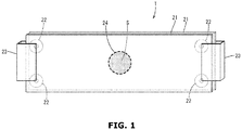
- FIG. 1 is an explanatory diagram of a test piece used in shear resistance evaluation.
- the thermally conductive material of the present embodiment is grease-like and used by being interposed between two objects (for example, a heat generating body and a heat dissipating body).
- the thermally conductive material has a viscosity that allows it to be discharged using a dispenser, but does not sag and retains its shape after application.
- the thermally conductive material mainly includes a crosslinking reaction product of an acrylic polymer (A) and an acrylic polymer (B), an acrylic polymer (C), a trimellitate ester plasticizer, a thermally conductive filler, and a thickener.
- the acrylic polymer (A) is an acrylic polymer that is a liquid (syrup-like) at room temperature and is used as the base material of the thermally conductive material.
- the acrylic polymer (A) includes at least two crosslinkable functional groups containing a carbon-carbon unsaturated bond.
- the acrylic polymer (A) preferably includes the crosslinkable functional groups at both ends.
- the viscosity (at 25°C) of the acrylic polymer (A) is not particularly limited as long as the object of the present invention is not impaired.
- the viscosity is preferably from 100000 mPa ⁇ s to 200000 mPa ⁇ s and more preferably from 120000 mPa ⁇ s to 180000 mPa ⁇ s, for example.
- the main chain of the acrylic polymer (A) is, for example, composed of a polymer of a (meth)acrylic acid monomer described below or a polymer of a (meth)acrylic acid monomer and another vinyl monomer.
- (meth)acrylic means that it includes both acryl and methacryl.
- Examples of the (meth)acrylic acid monomer include (meth)acrylic acid, methyl (meth)acrylate, ethyl (meth)acrylate, n-propyl (meth)acrylate, isopropyl (meth)acrylate, n-butyl (meth)acrylate, isobutyl (meth)acrylate, tert-butyl (meth)acrylate, n-pentyl (meth)acrylate, n-hexyl (meth)acrylate, cyclohexyl (meth)acrylate, n-heptyl (meth)acrylate, n-octyl (meth)acrylate, 2-ethylhexyl (meth)acrylate, nonyl (meth)acrylate, isononyl (meth)acrylate, decyl (meth)acrylate, dodecyl (meth)acrylate, phenyl (meth)acrylate, tolyl (me
- Examples of the other vinyl monomer include aromatic vinyl monomers such as styrene, vinyl toluene, ⁇ -methylstyrene, chlorostyrene, styrene sulfonic acid and salts thereof; fluorine-containing vinyl monomers such as perfluoroethylene, perfluoropropylene, and vinylidene fluoride; silicon-containing vinyl monomers such as vinyltrimethoxysilane and vinyltriethoxysilane; maleic anhydride, maleic acid, monoalkyl and dialkyl esters of maleic acid; fumaric acid, monoalkyl and dialkyl esters of fumaric acid; maleimide monomers such as maleimide, methylmaleimide, ethylmaleimide, propylmaleimide, butylmaleimide, hexylmaleimide, octylmaleimide, dodecylmaleimide, stearylmaleimide, phenylmaleimide, and cyclo
- the method for synthesizing the main chain of the acrylic polymer (A) is not particularly limited as long as the object of the present invention is not impaired.
- a free radical polymerization method may be used, but a living radical polymerization method is preferable because it easily reduces the molecular weight distribution (the ratio (Mw/Mn) of the weight average molecular weight (Mw) to the number average molecular weight (Mn)).
- the living radical polymerization method (particularly the atom transfer radical polymerization method) is preferable because it can obtain a polymer having a narrow molecular weight distribution and a low viscosity and because it can introduce a monomer having a specific functional group to almost any position in a polymer.
- the structure (functional group) represented by the chemical formula (1) is preferably, for example, an acryloyl group or a methacryloyl group and is particularly preferably an acryloyl group.
- the glass transition temperature of the acrylic polymer (A) is preferably - 40°C or less and more preferably -45°C or less.
- the acrylic polymer (B) is an acrylic polymer that is used (used in combination with) the acrylic polymer (A) as the base material (base resin) of the thermally conductive material and includes at least one crosslinkable functional group containing a carbon-carbon unsaturated bond.
- the acrylic polymer (B) preferably includes the crosslinkable functional group at one end. Note that the acrylic polymer (B) preferably has a lower viscosity and a smaller molecular weight (weight average molecular weight and number average molecular weight) than those of the acrylic polymer (A).
- the acrylic polymer (B) is a liquid (syrup-like) at room temperature and more often used as the base material (base resin) of a thermally conductive material than the acrylic polymer (A).
- the viscosity (at 25°C) of the acrylic polymer (B) is not particularly limited as long as the object of the present invention is not impaired. However, the viscosity is preferably from 35000 mPa ⁇ s to 60000 mPa ⁇ s and more preferably from 40000 mPa ⁇ s to 50000 mPa ⁇ s, for example.
- the ratio (mass ratio: Y/X) of a blended amount Y of the acrylic polymer (B) to a blended amount X of the acrylic polymer (A) is preferably 9 or greater, more preferably 12 or greater and preferably 49 or less and more preferably 30 or less.
- the main chain of the acrylic polymer (B) is basically, similar to that of the acrylic polymer (A) and is composed of a polymer of the (meth)acrylic acid monomer or a polymer of the (meth)acrylic acid monomer and the other vinyl monomer.
- the method for synthesizing the main chain of the acrylic polymer (B) is basically the same as that for the main chain of the acrylic polymer (A).
- the main chain of the acrylic polymer (B) is preferably shorter (molecular weight is less) than the acrylic polymer (B).
- the content of the crosslinkable functional group contained in the acrylic polymer (B) is similar to that of the acrylic polymer (A).
- the crosslinkable functional group of the acrylic polymer (B) includes a structure containing at least a carbon-carbon unsaturated bond and is composed of, for example, the structure (functional group) represented by the chemical formula (1).
- the structure (functional group) represented by the chemical formula (1) is preferably, for example, an acryloyl group or a methacryloyl group and is particularly preferably an acryloyl group.
- the glass transition temperature of the acrylic polymer (B) is preferably approximately the same as the glass transition temperature of the acrylic polymer (A) and is specifically preferably -40°C or less and more preferably - 45°C or less.
- the liquid acrylic polymer (C) with a viscosity of 650 mPa ⁇ s or less (at 25°C) is preferably further added.
- the mixture (composition) of the acrylic polymer (A), the acrylic polymer (B), and the acrylic polymer (C) is a liquid (syrup-like) having fluidity.
- the acrylic polymer (C) is preferably a polymer with no functionality that does not react and crosslink with the acrylic polymer (A) and the acrylic polymer (B). Also, the acrylic polymer (C) is preferably miscible with the acrylic polymer (A) and the acrylic polymer (B), being able to homogeneously mix with these.
- the viscosity (at 25°C) of the acrylic polymer (C) is preferably less than the viscosity of the acrylic polymer (A) and the viscosity of the acrylic polymer (B). Specifically, the viscosity (at 25°C) of the acrylic polymer (C) is 650 mPa ⁇ s or less, preferably 600 mPa ⁇ s or less, and more preferably 550 mPa ⁇ s or less.
- the acrylic polymer (C) with viscosity in this range is easily homogeneously mixed with the acrylic polymer (A) and the acrylic polymer (B).
- the acrylic polymer (C) preferably has a lower glass transition temperature than the acrylic polymer (A) and the acrylic polymer (B), the glass transition temperature being preferably -55°C or less, more preferably -65°C or less, and even more preferably -75°C or less, for example.
- the blended amount of the acrylic polymer (C) is from 100 parts by mass to 200 parts by mass per 100 parts by mass of the total blended amount of the acrylic polymer (A) and the acrylic polymer (B).
- a polymerization initiator (crosslinking initiator) is used when reacting and crosslinking the acrylic polymer (A) and the acrylic polymer (B).
- the polymerization initiator generates radicals by receiving heat or light and mainly has a function of reacting the crosslinkable functional group of the acrylic polymer (A) and the crosslinkable functional group of the acrylic polymer (B).
- radicals are generated by the crosslinking initiator, the crosslinkable functional groups are bonded (polymerized) and the acrylic polymer (A) and the acrylic polymer (B) are crosslinked and the acrylic polymers (B) are crosslinked.
- polymerization initiator examples include organic peroxides such as ketone peroxides, diacyl peroxides, hydroperoxides, dialkyl peroxides, peroxyketals, alkyl peresters, and percarbonates. Among these, percarbonates are particularly preferable.
- the polymerization initiator may be a photoreactive type that generate radicals by receiving light (for example, ultraviolet light) or a thermally reactive type that generates radicals by receiving heat.
- a thermally conductive filler or the like is added to the composition including the acrylic polymer (A), the acrylic polymer (B), and the acrylic polymer (C)
- the thermally conductive filler is included in the thermally conductive material.
- light for activating the polymerization initiator may be blocked.
- a thermally reactive type of crosslinking initiator is preferably used.
- reaction temperature is not particularly limited as long as the object of the present invention is not hindered.
- a polymerization initiator with a reaction temperature (heating temperature) of 100°C or greater is preferably used.
- the blended amount of the polymerization initiator is not particularly limited as long as the object of the present invention is not hindered.
- the blended amount is preferably 0.035 parts by mass or greater per 100 parts by mass of the total of the acrylic polymer (A) and the acrylic polymer (B).
- the upper limit of the blended amount of the polymerization initiation is, per 100 parts by mass of the total described above, preferably 0.1 parts by mass or less, more preferably 0.08 parts by mass or less, and even more preferably 0.065 parts by mass.
- a silane coupling agent may be further added to the composition including the acrylic polymer (A), the acrylic polymer (B), and the acrylic polymer (C) to adjust the viscosity or the like.
- the blended amount of the silane coupling agent is, per 100 parts by mass of the total of the acrylic polymer (A) and the acrylic polymer (B), 100 parts by mass or less and preferably 50 parts by mass or less, for example.
- trimellitate ester plasticizer examples include, for example, trioctyl trimellitate, triisononyl trimellitate, triisodecyl trimellitate, and 2-ethylhexyl trimellitate. These may be used alone or in combination of two or more of them.
- An example of a commercially available product able to be used as the trimellitate ester plasticizer includes the trade name "ADK CIZER (registered trademark) C-880" (available from Adeka Corporation).
- the blended amount of the trimellitate ester plasticizer is from 150 parts by mass to 350 parts by mass per 100 parts by mass of the total of the acrylic polymer (A) and the acrylic polymer (B).
- thermally conductive filler examples include silicon carbide, alumina (aluminum oxide), silica, silicon nitride, and boron nitride.
- Other examples include surface metal-coated particles composed of cores coated with a metal, the cores being made of hollow particles (for example, glass balloons) or of resin particles.
- One type of thermally conductive filler may be used, or a plurality of types may be used in combination. From among these, alumina (aluminum oxide) is preferably used.
- the average particle size of the thermally conductive filler is not particularly limited as long as the object of the present invention is not impaired and may be, for example, from 0.1 ⁇ m to 100 ⁇ m.
- a plurality of thermally conductive fillers with different particle sizes may be used.
- a thermally conductive filler with an average particle size of 100 ⁇ m or less in a certain ratio the stretchiness of the thermally conductive material can be ensured.
- a thermally conductive filler with an average particle size ranging from 0.1 ⁇ m to 1 ⁇ m in a certain ratio the viscosity of the thermally conductive material can be prevented from being too high.
- the average particle size of the thermally conductive filler is a volume-based average particle size (D50) obtained by a laser diffraction method.
- the average particle size can be measured by a laser diffraction type particle size distribution measurement instrument.
- the average particle size of the other particles described below is also a volume-based average particle size (D50) obtained by a laser diffraction method.
- the blended amount of the thermally conductive filler is from 3500 parts by mass to 7500 parts by mass per 100 parts by mass of the total of the acrylic polymer (A) and the acrylic polymer (B).
- a thermally conductive filler with an average particle size ranging from 0.1 ⁇ m to 0.5 ⁇ m, a thermally conductive filler with an average particle size ranging from 1 ⁇ m to 5 ⁇ m, a thermally conductive filler with an average particle size ranging from 10 ⁇ m to 20 ⁇ m, and a thermally conductive filler with an average particle size ranging from 30 ⁇ m to 50 ⁇ m may be used in combination.
- the blended amount of the thermally conductive filler with an average particle size ranging from 0.1 ⁇ m to 0.5 ⁇ m is preferably from 5 to 10 mass%
- the blended amount of the thermally conductive filler with an average particle size ranging from 1 ⁇ m to 5 ⁇ m is preferably from 20 to 30 mass%
- the blended amount of the thermally conductive filler with an average particle size ranging from 10 ⁇ m to 20 ⁇ m is preferably from 25 to 35 mass%
- the blended amount of the thermally conductive filler with an average particle size ranging from 30 ⁇ m to 50 ⁇ m is preferably from 30 to 40 mass%.
- a thickener for sag prevention, thixotropy improvement, and the like may be added to the thermally conductive material.
- a carbonate such as calcium carbonate is preferably used as the thickener, for example.
- the average particle size of the thickener is preferably 50 nm or less, for example.
- the blended amount of the thickener ranges from 50 parts by mass to 300 parts by mass per 100 parts by mass of the total of the acrylic polymer (A) and the acrylic polymer (B).
- the surface may be coated in fatty acid.
- a carbonate for example, calcium carbonate
- a carbonate that has undergone a coating treatment using a fatty acid may be used.
- the thermally conductive material may further include a metal hydroxide, an antioxidant, a coloring agent, a flame retardant, a plasticizer, a filler, and the like.
- a metal hydroxide may be added to give the thermally conductive material flame retardancy or to adjust the viscosity.
- An example of the metal hydroxide is magnesium hydroxide, for example.
- the metal hydroxide may be a metal hydroxide with a surface that has undergone a coating treatment using a higher fatty acid (surface treated metal hydroxide).
- Examples of the higher fatty acid include, for example, stearic acid, oleic acid, palmitic acid, linoleic acid, lauric acid, caprylic acid, behenic acid, montanic acid, and the like. Among these, oleic acid is preferable.
- the average particle size of the metal hydroxide is not particularly limited as long as the object of the present invention is not impaired.
- the average particle size is preferably 0.5 ⁇ m or greater and more preferably 1 ⁇ m or greater and preferably 10 ⁇ m or less and more preferably 5 ⁇ m or less.
- the viscosity of the thermally conductive material can be easily set to a viscosity that allows it to be discharged from a predetermined discharge device at a relatively low pressure and that allows it to retain its shape without sagging after being discharged.
- the blended amount of the metal hydroxide may range from 50 parts by mass to 500 parts by mass per 100 parts by mass of the total of the acrylic polymer (A) and the acrylic polymer (B).
- antioxidants examples include phenol-based antioxidants, phosphorus-based processing heat stabilizers, lactone-based processing heat stabilizers, sulfur-based heat-resistant stabilizers, phenol-phosphorus-based antioxidants, and the like.
- phenol-based antioxidants are preferable, and hindered phenol-based antioxidants are particularly preferable.
- the blended amount of the antioxidant is not particularly limited as long as the object of the present invention is not hindered. However, for example, the blended amount may range from 0.5 parts by mass to 2 parts by mass per 100 parts by mass of the total of the acrylic polymer (A) and the acrylic polymer (B).
- the composition for producing the thermally conductive material and the thermally conductive material have low viscosity and can retain a grease-like state without containing a solvent such as an organic solvent.
- a solvent such as an organic solvent.
- an organic solvent is not a required component and does not need to be actively added.
- an organic solvent may be used.
- crosslinking reaction products in which the acrylic polymer (A) and the acrylic polymer (B) are crosslinked (polymerized) and crosslinking reaction products in which the acrylic polymers (B) are crosslinked (polymerized) are included.
- the acrylic polymers are formed in a gently crosslinked structure.
- the overall crosslinking density of the acrylic polymers (the acrylic polymers (A) and (B)) can be presumed to be moderately low, and many free chains derived from mainly the acrylic polymer (B) can be presumed to be present.
- a plasticizer, thermally conductive filler, and the like are dispersed and blended in such an acrylic polymer. This allows the thermally conductive material to have a grease-like state with moderate hardness.
- the thermally conductive material has a viscosity (approximately 1000 Pa ⁇ s) that allows it to be discharged at a discharge pressure of approximately 0.2 MPa under a 25°C temperature condition. Also, the thermal conductivity of the thermally conductive material is 2 W/m ⁇ K or greater and preferably 3 W/m ⁇ K or greater.
- the thermally conductive material of the present embodiment includes an acrylic resin as the base resin, it does not have the problem of generating a siloxane gas, for example. Also, the thermally conductive material retains its shape after being applied via a dispenser, and sagging is minimized or prevented. Furthermore, the thermally conductive material does not have the problem of sagging from the nozzle tip of the dispenser, for example.
- the thermally conductive material has excellent heat resistance (shear resistance), with sagging from the installation position (for example, a gap between objects) caused by softening or the like being minimized or prevented under high temperature conditions (for example, 125°C or greater). Also, as described below, the physical properties of the thermally conductive material do not change after a hot/cold thermal shock, and the initial state is retained. Examples
- the acrylic polymer (A), the acrylic polymer (B), the acrylic polymer (C), and a polymerization initiator are blended together at the blended amounts (parts by mass) indicated in Table 1. After mixing, the mixture is heated for 10 minutes at 100°C to accelerate the crosslinking reaction (polymerization reaction). Then, with the obtained composition, a plasticizer (1), a silane coupling agent, an antioxidant, a coloring agent, aluminum oxide (1) to (5), a surface-treated magnesium hydroxide, and calcium carbonate are blended at the blended amount (parts by mass) indicated in Table 1. This is then kneaded using a kneader to produce the thermally conductive materials of Examples 1 to 3.
- acrylic polymer (A) trade name "KANEKA XMAP (registered trademark) RC100C” (available from Kaneka Corporation, acrylic polymer with acryloyl groups at both ends, viscosity: 160000 mPa ⁇ s (at 25°C), specific gravity: 1.05, glass transition temperature: -50°C.) was used.
- acrylic polymer (B) trade name "KANEKA XMAP (registered trademark) MM110C” (available from Kaneka Corporation, reactive acrylic macromonomer with an acryloyl group at one end, viscosity: 44000 mPa ⁇ s (at 25°C), specific gravity: 1.05, glass transition temperature: -50°C.) was used.
- acrylic polymer (C) trade name "ARUFON (registered trademark) UP-1020” (available from TOAGOSEI CO., LTD., a solventless acrylic polymer with no functional groups, viscosity: 500 mPa ⁇ s (at 25°C), weight average molecular weight: 2000, specific gravity: 1.03, glass transition temperature: -80°C.) was used.
- plasticizer (1) trade name "ADK CIZER (registered trademark) C-880” (available from Adeka Corporation, trimellitate ester plasticizer, viscosity: 220 mPa ⁇ s (at 25°C), glass transition temperature: -17°C) was used.
- silane coupling agent trade name "KBE-502" (available from Shin-Etsu Chemical Co., Ltd., 3-methacryloxypropyl methyldiethoxysilane) was used.
- antioxidant trade name "AO-60” (available from ADEKA Corporation, phenolic antioxidant, pentaerythritol tetrakis [3-(3,5-di-tert-butyl-4-hydroxyphenyl) propionate]) was used.
- aluminum oxide (1) trade name "AZ10-75” (available from NIPPON STEEL & SUMIKIN MATERIALS CO.,LTD., aluminum oxide (insulation grade), spherical, average particle size: 10 ⁇ m, specific gravity: 3.8) was used.
- Al oxide (2) trade name "AX3-75” (available from NIPPON STEEL & SUMIKIN MATERIALS CO.,LTD., aluminum oxide, spherical, average particle size: 3 ⁇ m, specific gravity: 3.8) was used.
- Al oxide (3) trade name "A10-C1" (available from Admatechs Co., Ltd., aluminum oxide, spherical, average particle size: 45 ⁇ m, specific gravity: 3.8) was used.
- aluminum oxide (4) trade name "AC2000-SML” (available from Admatechs Co., Ltd., aluminum oxide (methacrylsilane treatment), true sphere, average particle size: 0.2 ⁇ m, specific gravity: 3.6) was used.
- Al oxide (5) trade name "AX1M” (available from NIPPON STEEL & SUMIKIN MATERIALS CO.,LTD., aluminum oxide, spherical, average particle size: 1 ⁇ m, specific gravity: 3.8) was used.
- MAGSEEDS N-4 As the surface-treated magnesium hydroxide, trade name "MAGSEEDS N-4" (available from Konoshima Chemical Co., Ltd., particulate material of magnesium hydroxide particles surface-treated with oleic acid, average particle size: 1.3 ⁇ m, specific gravity: 2.4) was used.
- calcium carbonate trade name "Viscoexcel-30” (available from Shiraishi Kogyo Kaisha, Ltd., calcium carbonate (fatty acid treated), average particle size: 30 nm, specific gravity: 2.49) was used.
- Example 2 A similar process to that of Example 1 was used to produce a thermally conductive material according to Comparative Example 1, except that instead of the plasticizer (1), 250 parts by mass of the plasticizer (2) was blended, and a silane coupling agent was not blended.
- plasticizer (2) trade name "SANSO CIZER (registered trademark) DOS” (available from New Japan Chemical co., ltd., Di-2-ethylhexyl sebacate, viscosity: 13 mPa ⁇ s (at 25°C), weight average molecular weight: 426, glass transition temperature: -69°C) was used.
- acrylic polymer (D) trade name “ACRYCURE (registered trademark) HD-A218” (available from NIPPON SHOKUBAI CO., LTD., viscosity: 40 mPa ⁇ s (at 25°C)) was used.
- acrylic polymer (E) trade name "ACTFLOW (registered trademark) NE-1000” (available from Soken Chemical & Engineering Co., Ltd., weight average molecular weight: 3000, viscosity: from 700 to 1300 mPa ⁇ s (at 25°C)) was used.
- Thermally conductive materials according to the Examples and the Comparative Examples were discharged under a 25°C temperature condition, a discharge pressure of 0.2 MPa, and a discharge time of 1 minute, and the discharge amount per 10 seconds (g/10 s) of the thermally conductive materials was found.
- the results are indicated in Table 1. Note that the devices used are as follows.
- the thermal conductivity (W/m ⁇ K) of the thermally conductive materials according to the Examples and the Comparative Examples was measured via the hot-disk method. Note that in the measurement, a hot-disk thermal property measurement device (product name "TPS500” available from Hot Disk AB) was used. The size of the test pieces used to sandwich the polyimide sensor was 30 mm x 30 mm x 7 mm. The results are indicated in Table 1.
- FIG. 1 is an explanatory diagram of a test piece T used in the shear resistance evaluation.
- two glass plates (glass slides) 21 were prepared, 1 g of a thermally conductive material S was put between them with a spacer (a washer having a thickness of 1.0 mm) 22 was also interposed therebetween, and the thermally conductive material S was sandwiched between the two glass plates 21, forming it in a circular shape.
- the glass plates 21 were fixed together using clips 23.
- the outline of the thermally conductive material S was indicated on the surface of the glass plate 21 with an oil-based marker.
- the test piece T thus obtained was placed in a thermal shock tester (product name "TSE-11-A", available from Espec Co., Ltd.) so that the flat circular thermally conductive material S stood upright in the vertical direction and was left for 100 hours at a temperature condition of 125° C. Thereafter, how much the thermally conductive material S sagged (displaced) from the original position (initial position) was measured, and the evaluation was determined on the basis of the evaluation criteria described below. The results are indicated in Table 1.
- Test pieces according to the Examples and the Comparative Examples were manufactured in a similar manner to the sagging test, except that the thickness of the spacer interposed between the two glass plates was changed to 0.5 mm and the amount of the thermally conductive material placed between the two glass plates was changed to 0.5 g.
- the thermal shock tester the obtained test pieces were subjected to a cold/hot cycle test (number of cycles: 100) in which in a horizontal state (the glass plates being horizontal), the temperature is repeatedly alternated between -40°C and 125°C (30 minutes each). Thereafter, whether cracking is present in the test piece of the thermally conductive material was visually checked.
- the results are indicated in Table 1. Note that a case where there is no cracking is indicated by "Good”, and a case where there is cracking is indicated by "Fail”.
- test pieces according to the Examples and the Comparative Examples were manufactured in a similar manner to the sagging test. Using the thermal shock tester, the obtained test pieces were placed in a horizontal state (the glass plates being horizontal) and left for 500 hours in a temperature condition of 125°C. Thereafter, whether the test piece of the thermally conductive material degraded was visually checked. The results are indicated in Table 1. Note that a case where there is no degradation is indicated by "Good”, and a case where there is degradation is indicated by "Fail”.
- the thermally conductive materials according to Examples 1 to 3 have excellent thermal conductivity with a thermal conductivity of 3.0 W/m ⁇ K. Also, it can be seen that the thermally conductive materials of Examples 1 to 3 have excellent heat resistance. Even though the thermally conductive materials according to Examples 1 to 3 have a viscosity (fluidity) that allow them to be discharged at a relatively low pressure of 0.2 MPa, when the thermally conductive materials are used in high temperature conditions, no sagging occurs and their shape is retained.
- the liquid component such as the plasticizer (2) of the thermally conductive materials according to Comparative Examples 1 to 6 volatilized and was reduced, causing the thermally conductive materials to become dry and brittle. Also, in the thermally conductive materials according to Comparative Examples 1 to 6, discoloration (yellowing) occurred. In particular, in the sagging test results for Comparative Example 6, in which calcium carbonate was not added, the thermally conductive material sagged. Note that in the thermally conductive materials according to Comparative Examples 1 to 6, the plasticizer (2) that leaked to the outside melt the surrounding members (for example, members made of a plastic such as polycarbonate) when it comes into contact with them. Thus, for this reason also, the plasticizer (2) is preferably not used.
Abstract
Description
- The present invention relates to a thermally conductive material.
- A known grease-like thermally conductive material is used to fill in small gaps or the like formed between a heat generating body and a heat dissipating body (see Patent Documents 1 to 3, for example). Grease-like thermally conductive materials become widely used in recent years due to their excellent adhesion and the great flexibility they provide in terms of being able to fill gaps of a variety of sizes and shapes.
- This type of thermally conductive material mainly includes a resin component as a base material and a thermally conductive filler disperse therein. Note that in thermally conductive materials, silicone resin is often used as the resin component to give the thermally conductive material the required heat resistance (for example, 100°C or greater).
-
- Patent Document 1:
JP 2015-140395 A - Patent Document 2:
JP 2010-242022 A - Patent Document 3:
US 7208192 B Specification - Thermally conductive materials made using a silicone resin are problematic as they may produce a siloxane gas (for example, a cyclic siloxane gas). Because siloxane gas causes problems such as contact failure in an electronic apparatus, there is a demand for a thermally conductive material including a non-silicone resin that does not produce a siloxane gas.
- However, known thermally conductive materials including a non-silicone resin have insufficient heat resistance and thus have room for improvement.
- The present invention is directed at providing a grease-like thermally conductive material that includes a non-silicone resin and has excellent heat resistance.
- The solutions to the above-described problems are as follows.
- 1. A thermally conductive material includes:
- 100 parts by mass of a crosslinking reaction product of an acrylic polymer (A) including at least two crosslinkable functional groups containing a carbon-carbon unsaturated bond and an acrylic polymer (B) including at least one of the crosslinkable functional groups;
- from 100 to 200 parts by mass of an acrylic polymer (C) with a viscosity of 650 mPa·s or less;
- from 150 to 350 parts by mass of a trimellitate ester plasticizer;
- from 3500 to 7500 parts by mass of a thermally conductive filler with an average particle size ranging from 0.1 µm to 100 µm; and
- from 50 to 300 parts by mass of a thickener with an average particle size of 50 nm or less.
- 2. The thermally conductive material according to 1, wherein the thermally conductive filler includes aluminum oxide.
- 3. The thermally conductive material according to 1 or 2, wherein the thickener is calcium carbonate.
- 4. The thermally conductive material according to any one of 1 to 3, wherein a ratio (mass ratio: Y/X) of a blended amount Y of the acrylic polymer (B) to a blended amount X of the acrylic polymer (A) is from 9 to 49.
- According to the present invention, a grease-like thermally conductive material that includes a non-silicone resin and has excellent heat resistance is provided.
-
FIG. 1 is an explanatory diagram of a test piece used in shear resistance evaluation. - The thermally conductive material of the present embodiment is grease-like and used by being interposed between two objects (for example, a heat generating body and a heat dissipating body). The thermally conductive material has a viscosity that allows it to be discharged using a dispenser, but does not sag and retains its shape after application.
- The thermally conductive material mainly includes a crosslinking reaction product of an acrylic polymer (A) and an acrylic polymer (B), an acrylic polymer (C), a trimellitate ester plasticizer, a thermally conductive filler, and a thickener.
- The acrylic polymer (A) is an acrylic polymer that is a liquid (syrup-like) at room temperature and is used as the base material of the thermally conductive material. The acrylic polymer (A) includes at least two crosslinkable functional groups containing a carbon-carbon unsaturated bond. The acrylic polymer (A) preferably includes the crosslinkable functional groups at both ends.
- The viscosity (at 25°C) of the acrylic polymer (A) is not particularly limited as long as the object of the present invention is not impaired. However, the viscosity is preferably from 100000 mPa·s to 200000 mPa·s and more preferably from 120000 mPa·s to 180000 mPa·s, for example.
- The main chain of the acrylic polymer (A) is, for example, composed of a polymer of a (meth)acrylic acid monomer described below or a polymer of a (meth)acrylic acid monomer and another vinyl monomer. In the present specification, "(meth)acrylic" means that it includes both acryl and methacryl.
- Examples of the (meth)acrylic acid monomer include (meth)acrylic acid, methyl (meth)acrylate, ethyl (meth)acrylate, n-propyl (meth)acrylate, isopropyl (meth)acrylate, n-butyl (meth)acrylate, isobutyl (meth)acrylate, tert-butyl (meth)acrylate, n-pentyl (meth)acrylate, n-hexyl (meth)acrylate, cyclohexyl (meth)acrylate, n-heptyl (meth)acrylate, n-octyl (meth)acrylate, 2-ethylhexyl (meth)acrylate, nonyl (meth)acrylate, isononyl (meth)acrylate, decyl (meth)acrylate, dodecyl (meth)acrylate, phenyl (meth)acrylate, tolyl (meth)acrylate, benzyl (meth)acrylate, 2-methoxyethyl (meth)acrylate, 3-methoxybutyl (meth)acrylate, 2-hydroxyethyl (meth)acrylate, 2-hydroxypropyl (meth)acrylate, octadecyl (meth)acrylate, glycidyl (meth)acrylate, 2-aminoethyl (meth)acrylate, γ-(methacryloyloxypropyl) trimethoxysilane, ethylene oxide adduct of (meth)acrylic acid, trifluoromethylmethyl (meth)acrylate, 2-trifluoromethylethyl (meth)acrylate, perfluoroethyl methyl (meth)acrylate, 2-perfluoroethyl ethyl (meth)acrylate, perfluoroethyl perfluorobutyl methyl (meth)acrylate, 2-perfluoroethyl-2-perfluorobutyl ethyl (meth)acrylate, perfluoroethyl (meth)acrylate, perfluoromethyl (meth)acrylate, diperfluoromethyl methyl (meth)acrylate, 2,2-diperfluoromethylethyl (meth)acrylate, perfluoromethyl perfluoroethylmethyl (meth)acrylate, 2-perfluoromethyl-2-perfluoroethylethyl (meth)acrylate, 2-perfluorohexylmethyl (meth)acrylate, 2-perfluorohexylethyl (meth)acrylate, (2-perfluorodecylmethyl (meth)acrylate, 2-perfluorodecylethyl (meth)acrylate, 2-perfluorohexadecylmethyl (meth)acrylate, and 2-perfluorohexadecylethyl (meth)acrylate. These may be used alone or in combination of two or more of them.
- Examples of the other vinyl monomer include aromatic vinyl monomers such as styrene, vinyl toluene, α-methylstyrene, chlorostyrene, styrene sulfonic acid and salts thereof; fluorine-containing vinyl monomers such as perfluoroethylene, perfluoropropylene, and vinylidene fluoride; silicon-containing vinyl monomers such as vinyltrimethoxysilane and vinyltriethoxysilane; maleic anhydride, maleic acid, monoalkyl and dialkyl esters of maleic acid; fumaric acid, monoalkyl and dialkyl esters of fumaric acid; maleimide monomers such as maleimide, methylmaleimide, ethylmaleimide, propylmaleimide, butylmaleimide, hexylmaleimide, octylmaleimide, dodecylmaleimide, stearylmaleimide, phenylmaleimide, and cyclohexylmaleimide; acrylonitrile monomers such as acrylonitrile and methacrylonitrile; amide group-containing vinyl monomers such as acrylamide and methacrylamide; vinyl esters such as vinyl acetate, vinyl propionate, vinyl pivalate, vinyl benzoate and vinyl cinnamate; alkenes such as ethylene and propylene; conjugated dienes such as butadiene and isoprene; vinyl chloride, vinylidene chloride, allyl chloride, and allyl alcohol. These may be used alone or in combination of two or more of them.
- The method for synthesizing the main chain of the acrylic polymer (A) is not particularly limited as long as the object of the present invention is not impaired. For example, a free radical polymerization method may be used, but a living radical polymerization method is preferable because it easily reduces the molecular weight distribution (the ratio (Mw/Mn) of the weight average molecular weight (Mw) to the number average molecular weight (Mn)). The living radical polymerization method (particularly the atom transfer radical polymerization method) is preferable because it can obtain a polymer having a narrow molecular weight distribution and a low viscosity and because it can introduce a monomer having a specific functional group to almost any position in a polymer.
- The crosslinkable functional group includes a structure containing at least a carbon-carbon unsaturated bond and is composed of, for example, the structure (functional group) represented by the chemical formula (1) below:
-OC(O)C(R) = CH2 (1)
where R represents a hydrogen atom or an organic group having from 1 to 20 carbon atoms. - The structure (functional group) represented by the chemical formula (1) is preferably, for example, an acryloyl group or a methacryloyl group and is particularly preferably an acryloyl group.
- The glass transition temperature of the acrylic polymer (A) is preferably - 40°C or less and more preferably -45°C or less.
- The acrylic polymer (B) is an acrylic polymer that is used (used in combination with) the acrylic polymer (A) as the base material (base resin) of the thermally conductive material and includes at least one crosslinkable functional group containing a carbon-carbon unsaturated bond. The acrylic polymer (B) preferably includes the crosslinkable functional group at one end. Note that the acrylic polymer (B) preferably has a lower viscosity and a smaller molecular weight (weight average molecular weight and number average molecular weight) than those of the acrylic polymer (A).
- The acrylic polymer (B) is a liquid (syrup-like) at room temperature and more often used as the base material (base resin) of a thermally conductive material than the acrylic polymer (A). The viscosity (at 25°C) of the acrylic polymer (B) is not particularly limited as long as the object of the present invention is not impaired. However, the viscosity is preferably from 35000 mPa·s to 60000 mPa·s and more preferably from 40000 mPa·s to 50000 mPa·s, for example.
- For example, in the thermally conductive material, the ratio (mass ratio: Y/X) of a blended amount Y of the acrylic polymer (B) to a blended amount X of the acrylic polymer (A) is preferably 9 or greater, more preferably 12 or greater and preferably 49 or less and more preferably 30 or less.
- The main chain of the acrylic polymer (B) is basically, similar to that of the acrylic polymer (A) and is composed of a polymer of the (meth)acrylic acid monomer or a polymer of the (meth)acrylic acid monomer and the other vinyl monomer. The method for synthesizing the main chain of the acrylic polymer (B) is basically the same as that for the main chain of the acrylic polymer (A). However, the main chain of the acrylic polymer (B) is preferably shorter (molecular weight is less) than the acrylic polymer (B).
- The content of the crosslinkable functional group contained in the acrylic polymer (B) is similar to that of the acrylic polymer (A). The crosslinkable functional group of the acrylic polymer (B) includes a structure containing at least a carbon-carbon unsaturated bond and is composed of, for example, the structure (functional group) represented by the chemical formula (1). For the crosslinkable functional group of the acrylic polymer (B) also, the structure (functional group) represented by the chemical formula (1) is preferably, for example, an acryloyl group or a methacryloyl group and is particularly preferably an acryloyl group.
- The glass transition temperature of the acrylic polymer (B) is preferably approximately the same as the glass transition temperature of the acrylic polymer (A) and is specifically preferably -40°C or less and more preferably - 45°C or less.
- When a crosslinking (polymerizing) reaction occurs between the acrylic polymer (A) and the acrylic polymer (B), the liquid acrylic polymer (C) with a viscosity of 650 mPa·s or less (at 25°C) is preferably further added. The mixture (composition) of the acrylic polymer (A), the acrylic polymer (B), and the acrylic polymer (C) is a liquid (syrup-like) having fluidity.
- The acrylic polymer (C) is preferably a polymer with no functionality that does not react and crosslink with the acrylic polymer (A) and the acrylic polymer (B). Also, the acrylic polymer (C) is preferably miscible with the acrylic polymer (A) and the acrylic polymer (B), being able to homogeneously mix with these.
- The viscosity (at 25°C) of the acrylic polymer (C) is preferably less than the viscosity of the acrylic polymer (A) and the viscosity of the acrylic polymer (B). Specifically, the viscosity (at 25°C) of the acrylic polymer (C) is 650 mPa·s or less, preferably 600 mPa·s or less, and more preferably 550 mPa·s or less. The acrylic polymer (C) with viscosity in this range is easily homogeneously mixed with the acrylic polymer (A) and the acrylic polymer (B).
- The acrylic polymer (C) preferably has a lower glass transition temperature than the acrylic polymer (A) and the acrylic polymer (B), the glass transition temperature being preferably -55°C or less, more preferably -65°C or less, and even more preferably -75°C or less, for example.
- The blended amount of the acrylic polymer (C) is from 100 parts by mass to 200 parts by mass per 100 parts by mass of the total blended amount of the acrylic polymer (A) and the acrylic polymer (B).
- A polymerization initiator (crosslinking initiator) is used when reacting and crosslinking the acrylic polymer (A) and the acrylic polymer (B). The polymerization initiator generates radicals by receiving heat or light and mainly has a function of reacting the crosslinkable functional group of the acrylic polymer (A) and the crosslinkable functional group of the acrylic polymer (B). When radicals are generated by the crosslinking initiator, the crosslinkable functional groups are bonded (polymerized) and the acrylic polymer (A) and the acrylic polymer (B) are crosslinked and the acrylic polymers (B) are crosslinked.
- Examples of the polymerization initiator include organic peroxides such as ketone peroxides, diacyl peroxides, hydroperoxides, dialkyl peroxides, peroxyketals, alkyl peresters, and percarbonates. Among these, percarbonates are particularly preferable.
- The polymerization initiator may be a photoreactive type that generate radicals by receiving light (for example, ultraviolet light) or a thermally reactive type that generates radicals by receiving heat. Note that, in a case where a thermally conductive filler or the like is added to the composition including the acrylic polymer (A), the acrylic polymer (B), and the acrylic polymer (C), the thermally conductive filler is included in the thermally conductive material. Thus, light for activating the polymerization initiator may be blocked. For this reason, a thermally reactive type of crosslinking initiator is preferably used.
- Note that in a case where a thermally reactive type of polymerization initiator, the reaction temperature is not particularly limited as long as the object of the present invention is not hindered. For example, from the perspective of ensuring storage stability of the composition, a polymerization initiator with a reaction temperature (heating temperature) of 100°C or greater is preferably used.
- The blended amount of the polymerization initiator is not particularly limited as long as the object of the present invention is not hindered. However, for example, the blended amount is preferably 0.035 parts by mass or greater per 100 parts by mass of the total of the acrylic polymer (A) and the acrylic polymer (B). Note that the upper limit of the blended amount of the polymerization initiation is, per 100 parts by mass of the total described above, preferably 0.1 parts by mass or less, more preferably 0.08 parts by mass or less, and even more preferably 0.065 parts by mass. With the blended amount of the polymerization initiation set in such a range, heat resistance (shear resistance) of the thermally conductive material is easily ensured.
- Note that a silane coupling agent may be further added to the composition including the acrylic polymer (A), the acrylic polymer (B), and the acrylic polymer (C) to adjust the viscosity or the like.
- The blended amount of the silane coupling agent is, per 100 parts by mass of the total of the acrylic polymer (A) and the acrylic polymer (B), 100 parts by mass or less and preferably 50 parts by mass or less, for example.
- Examples of the trimellitate ester plasticizer include, for example, trioctyl trimellitate, triisononyl trimellitate, triisodecyl trimellitate, and 2-ethylhexyl trimellitate. These may be used alone or in combination of two or more of them. An example of a commercially available product able to be used as the trimellitate ester plasticizer includes the trade name "ADK CIZER (registered trademark) C-880" (available from Adeka Corporation).
- The blended amount of the trimellitate ester plasticizer is from 150 parts by mass to 350 parts by mass per 100 parts by mass of the total of the acrylic polymer (A) and the acrylic polymer (B).
- Examples of the thermally conductive filler include silicon carbide, alumina (aluminum oxide), silica, silicon nitride, and boron nitride. Other examples include surface metal-coated particles composed of cores coated with a metal, the cores being made of hollow particles (for example, glass balloons) or of resin particles. One type of thermally conductive filler may be used, or a plurality of types may be used in combination. From among these, alumina (aluminum oxide) is preferably used.
- The average particle size of the thermally conductive filler is not particularly limited as long as the object of the present invention is not impaired and may be, for example, from 0.1 µm to 100 µm. A plurality of thermally conductive fillers with different particle sizes may be used. By using a thermally conductive filler with an average particle size of 100 µm or less in a certain ratio, the stretchiness of the thermally conductive material can be ensured. Also, by using a thermally conductive filler with an average particle size ranging from 0.1 µm to 1 µm in a certain ratio, the viscosity of the thermally conductive material can be prevented from being too high.
- Note that the average particle size of the thermally conductive filler is a volume-based average particle size (D50) obtained by a laser diffraction method. The average particle size can be measured by a laser diffraction type particle size distribution measurement instrument. Note that the average particle size of the other particles described below is also a volume-based average particle size (D50) obtained by a laser diffraction method.
- The blended amount of the thermally conductive filler is from 3500 parts by mass to 7500 parts by mass per 100 parts by mass of the total of the acrylic polymer (A) and the acrylic polymer (B).
- For example, a thermally conductive filler with an average particle size ranging from 0.1 µm to 0.5 µm, a thermally conductive filler with an average particle size ranging from 1 µm to 5 µm, a thermally conductive filler with an average particle size ranging from 10 µm to 20 µm, and a thermally conductive filler with an average particle size ranging from 30 µm to 50 µm may be used in combination. In this case, regarding the overall blended amount of the thermally conductive filler, the blended amount of the thermally conductive filler with an average particle size ranging from 0.1 µm to 0.5 µm is preferably from 5 to 10 mass%, the blended amount of the thermally conductive filler with an average particle size ranging from 1 µm to 5 µm is preferably from 20 to 30 mass%, the blended amount of the thermally conductive filler with an average particle size ranging from 10 µm to 20 µm is preferably from 25 to 35 mass%, and the blended amount of the thermally conductive filler with an average particle size ranging from 30 µm to 50 µm is preferably from 30 to 40 mass%.
- A thickener for sag prevention, thixotropy improvement, and the like may be added to the thermally conductive material. A carbonate such as calcium carbonate is preferably used as the thickener, for example. The average particle size of the thickener is preferably 50 nm or less, for example. The blended amount of the thickener ranges from 50 parts by mass to 300 parts by mass per 100 parts by mass of the total of the acrylic polymer (A) and the acrylic polymer (B). Note that in a case where the thickener is made of a carbonate, the surface may be coated in fatty acid. In other words, a carbonate (for example, calcium carbonate) that has undergone a coating treatment using a fatty acid may be used.
- The thermally conductive material may further include a metal hydroxide, an antioxidant, a coloring agent, a flame retardant, a plasticizer, a filler, and the like.
- A metal hydroxide may be added to give the thermally conductive material flame retardancy or to adjust the viscosity. An example of the metal hydroxide is magnesium hydroxide, for example. The metal hydroxide may be a metal hydroxide with a surface that has undergone a coating treatment using a higher fatty acid (surface treated metal hydroxide). Examples of the higher fatty acid include, for example, stearic acid, oleic acid, palmitic acid, linoleic acid, lauric acid, caprylic acid, behenic acid, montanic acid, and the like. Among these, oleic acid is preferable. The average particle size of the metal hydroxide is not particularly limited as long as the object of the present invention is not impaired. However, the average particle size is preferably 0.5 µm or greater and more preferably 1 µm or greater and preferably 10 µm or less and more preferably 5 µm or less. With the average particle size of the metal hydroxide being in this range, the viscosity of the thermally conductive material can be easily set to a viscosity that allows it to be discharged from a predetermined discharge device at a relatively low pressure and that allows it to retain its shape without sagging after being discharged.
- The blended amount of the metal hydroxide may range from 50 parts by mass to 500 parts by mass per 100 parts by mass of the total of the acrylic polymer (A) and the acrylic polymer (B).
- Examples of the antioxidant include phenol-based antioxidants, phosphorus-based processing heat stabilizers, lactone-based processing heat stabilizers, sulfur-based heat-resistant stabilizers, phenol-phosphorus-based antioxidants, and the like. Among these, phenol-based antioxidants are preferable, and hindered phenol-based antioxidants are particularly preferable. The blended amount of the antioxidant is not particularly limited as long as the object of the present invention is not hindered. However, for example, the blended amount may range from 0.5 parts by mass to 2 parts by mass per 100 parts by mass of the total of the acrylic polymer (A) and the acrylic polymer (B).
- The composition for producing the thermally conductive material and the thermally conductive material have low viscosity and can retain a grease-like state without containing a solvent such as an organic solvent. Thus, an organic solvent is not a required component and does not need to be actively added. However, as long as the object of the present invention is not hindered, an organic solvent may be used.
- In the thermally conductive material of the present embodiment, crosslinking reaction products in which the acrylic polymer (A) and the acrylic polymer (B) are crosslinked (polymerized) and crosslinking reaction products in which the acrylic polymers (B) are crosslinked (polymerized) are included. In other words, in the thermally conductive material, the acrylic polymers are formed in a gently crosslinked structure. In the thermally conductive material, the overall crosslinking density of the acrylic polymers (the acrylic polymers (A) and (B)) can be presumed to be moderately low, and many free chains derived from mainly the acrylic polymer (B) can be presumed to be present. Also, a plasticizer, thermally conductive filler, and the like are dispersed and blended in such an acrylic polymer. This allows the thermally conductive material to have a grease-like state with moderate hardness.
- The thermally conductive material has a viscosity (approximately 1000 Pa·s) that allows it to be discharged at a discharge pressure of approximately 0.2 MPa under a 25°C temperature condition. Also, the thermal conductivity of the thermally conductive material is 2 W/m·K or greater and preferably 3 W/m·K or greater.
- Since the thermally conductive material of the present embodiment includes an acrylic resin as the base resin, it does not have the problem of generating a siloxane gas, for example. Also, the thermally conductive material retains its shape after being applied via a dispenser, and sagging is minimized or prevented. Furthermore, the thermally conductive material does not have the problem of sagging from the nozzle tip of the dispenser, for example. The thermally conductive material has excellent heat resistance (shear resistance), with sagging from the installation position (for example, a gap between objects) caused by softening or the like being minimized or prevented under high temperature conditions (for example, 125°C or greater). Also, as described below, the physical properties of the thermally conductive material do not change after a hot/cold thermal shock, and the initial state is retained. Examples
- The present invention will be described in further detail below using examples. Note that the present invention is not limited in any manner by the examples.
- The acrylic polymer (A), the acrylic polymer (B), the acrylic polymer (C), and a polymerization initiator are blended together at the blended amounts (parts by mass) indicated in Table 1. After mixing, the mixture is heated for 10 minutes at 100°C to accelerate the crosslinking reaction (polymerization reaction). Then, with the obtained composition, a plasticizer (1), a silane coupling agent, an antioxidant, a coloring agent, aluminum oxide (1) to (5), a surface-treated magnesium hydroxide, and calcium carbonate are blended at the blended amount (parts by mass) indicated in Table 1. This is then kneaded using a kneader to produce the thermally conductive materials of Examples 1 to 3.
- As the acrylic polymer (A), trade name "KANEKA XMAP (registered trademark) RC100C" (available from Kaneka Corporation, acrylic polymer with acryloyl groups at both ends, viscosity: 160000 mPa·s (at 25°C), specific gravity: 1.05, glass transition temperature: -50°C.) was used.
- As the acrylic polymer (B), trade name "KANEKA XMAP (registered trademark) MM110C" (available from Kaneka Corporation, reactive acrylic macromonomer with an acryloyl group at one end, viscosity: 44000 mPa·s (at 25°C), specific gravity: 1.05, glass transition temperature: -50°C.) was used.
- As the acrylic polymer (C), trade name "ARUFON (registered trademark) UP-1020" (available from TOAGOSEI CO., LTD., a solventless acrylic polymer with no functional groups, viscosity: 500 mPa·s (at 25°C), weight average molecular weight: 2000, specific gravity: 1.03, glass transition temperature: -80°C.) was used.
- As the polymerization initiator, trade name "PERKADOX (registered trademark) 16" (available from Kayaku Akzo Corporation, di-(4-tert-butylcyclohexyl) peroxydicarbonate (mixture)) was used.
- As the plasticizer (1), trade name "ADK CIZER (registered trademark) C-880" (available from Adeka Corporation, trimellitate ester plasticizer, viscosity: 220 mPa·s (at 25°C), glass transition temperature: -17°C) was used.
- As the silane coupling agent, trade name "KBE-502" (available from Shin-Etsu Chemical Co., Ltd., 3-methacryloxypropyl methyldiethoxysilane) was used.
- As the antioxidant, trade name "AO-60" (available from ADEKA Corporation, phenolic antioxidant, pentaerythritol tetrakis [3-(3,5-di-tert-butyl-4-hydroxyphenyl) propionate]) was used.
- As the coloring agent, trade name "#7403 (black)" (available from Dainichiseika Color & Chemicals Mfg. Co., Ltd.) was used.
- As the aluminum oxide (1), trade name "AZ10-75" (available from NIPPON STEEL & SUMIKIN MATERIALS CO.,LTD., aluminum oxide (insulation grade), spherical, average particle size: 10 µm, specific gravity: 3.8) was used.
- As the aluminum oxide (2), trade name "AX3-75" (available from NIPPON STEEL & SUMIKIN MATERIALS CO.,LTD., aluminum oxide, spherical, average particle size: 3 µm, specific gravity: 3.8) was used.
- As the aluminum oxide (3), trade name "A10-C1" (available from Admatechs Co., Ltd., aluminum oxide, spherical, average particle size: 45 µm, specific gravity: 3.8) was used.
- As the aluminum oxide (4), trade name "AC2000-SML" (available from Admatechs Co., Ltd., aluminum oxide (methacrylsilane treatment), true sphere, average particle size: 0.2 µm, specific gravity: 3.6) was used.
- As the aluminum oxide (5), trade name "AX1M" (available from NIPPON STEEL & SUMIKIN MATERIALS CO.,LTD., aluminum oxide, spherical, average particle size: 1 µm, specific gravity: 3.8) was used.
- As the surface-treated magnesium hydroxide, trade name "MAGSEEDS N-4" (available from Konoshima Chemical Co., Ltd., particulate material of magnesium hydroxide particles surface-treated with oleic acid, average particle size: 1.3 µm, specific gravity: 2.4) was used.
- As the calcium carbonate, trade name "Viscoexcel-30" (available from Shiraishi Kogyo Kaisha, Ltd., calcium carbonate (fatty acid treated), average particle size: 30 nm, specific gravity: 2.49) was used.
- A similar process to that of Example 1 was used to produce a thermally conductive material according to Comparative Example 1, except that instead of the plasticizer (1), 250 parts by mass of the plasticizer (2) was blended, and a silane coupling agent was not blended.
- Note that as the plasticizer (2), trade name "SANSO CIZER (registered trademark) DOS" (available from New Japan Chemical co., ltd., Di-2-ethylhexyl sebacate, viscosity: 13 mPa·s (at 25°C), weight average molecular weight: 426, glass transition temperature: -69°C) was used.
- A similar process to that of Comparative Example 1 was used to produce a thermally conductive material according to Comparative Example 2, except that instead of the acrylic polymer (C), 150 parts by mass of an acrylic polymer (D) was blended.
- Note that as the acrylic polymer (D), trade name "ACRYCURE (registered trademark) HD-A218" (available from NIPPON SHOKUBAI CO., LTD., viscosity: 40 mPa·s (at 25°C)) was used.
- A similar process to that of Comparative Example 1 was used to produce a thermally conductive material according to Comparative Example 3, except that instead of the acrylic polymer (C), 150 parts by mass of an acrylic polymer (E) was blended.
- Note that as the acrylic polymer (E), trade name "ACTFLOW (registered trademark) NE-1000" (available from Soken Chemical & Engineering Co., Ltd., weight average molecular weight: 3000, viscosity: from 700 to 1300 mPa·s (at 25°C)) was used.
- A similar process to that of Comparative Example 1 was used to produce a thermally conductive material according to Comparative Example 4, except that the blended amount of the acrylic polymer (B) was changed in 245 parts by mass, the acrylic polymer (C) and the silane coupling agent were not blended, and instead of the plasticizer (1), 250 parts by mass of the plasticizer (2) was blended.
- A similar process to that of Comparative Example 4 was used to produce a thermally conductive material according to Comparative Example 5, except that magnesium hydroxide was not blended and the blended amount of calcium carbonate was changed to 250 parts by mass.
- A similar process to that of Comparative Example 4 was used to produce a thermally conductive material according to Comparative Example 6, except that the magnesium hydroxide and the calcium carbonate were not blended.
- Thermally conductive materials according to the Examples and the Comparative Examples were discharged under a 25°C temperature condition, a discharge pressure of 0.2 MPa, and a discharge time of 1 minute, and the discharge amount per 10 seconds (g/10 s) of the thermally conductive materials was found. The results are indicated in Table 1. Note that the devices used are as follows.
- Dispenser controller: product name "SMART SHOT MS-1D" (available from Musashi Engineering, Inc.)
- Syringe: product name "PSY-30E" (available from Musashi Engineering, Inc., nozzle inner diameter: 2 mm, inner diameter of portion containing thermally conductive material (i.e., chemical solution portion): 26.2 mm)
- The thermal conductivity (W/m·K) of the thermally conductive materials according to the Examples and the Comparative Examples was measured via the hot-disk method. Note that in the measurement, a hot-disk thermal property measurement device (product name "TPS500" available from Hot Disk AB) was used. The size of the test pieces used to sandwich the polyimide sensor was 30 mm x 30 mm x 7 mm. The results are indicated in Table 1.
- The shear resistance (sagging resistance) of the thermally conductive materials according to the Examples and the Comparative Examples was evaluated using the method described below.
FIG. 1 is an explanatory diagram of a test piece T used in the shear resistance evaluation. As illustrated inFIG. 1 , two glass plates (glass slides) 21 were prepared, 1 g of a thermally conductive material S was put between them with a spacer (a washer having a thickness of 1.0 mm) 22 was also interposed therebetween, and the thermally conductive material S was sandwiched between the twoglass plates 21, forming it in a circular shape. Theglass plates 21 were fixed together using clips 23. In order to indicate the initial position of the thermally conductive material S, the outline of the thermally conductive material S was indicated on the surface of theglass plate 21 with an oil-based marker. The test piece T thus obtained was placed in a thermal shock tester (product name "TSE-11-A", available from Espec Co., Ltd.) so that the flat circular thermally conductive material S stood upright in the vertical direction and was left for 100 hours at a temperature condition of 125° C. Thereafter, how much the thermally conductive material S sagged (displaced) from the original position (initial position) was measured, and the evaluation was determined on the basis of the evaluation criteria described below. The results are indicated in Table 1. -
- "Good" No sagging (when the amount of displacement is within 5%)
- "Marginal" Slightly sagged (when the amount of displacement is less than 50%)
- "Fail" Sagged (when the amount of displacement is 50% or greater)
- Test pieces according to the Examples and the Comparative Examples were manufactured in a similar manner to the sagging test, except that the thickness of the spacer interposed between the two glass plates was changed to 0.5 mm and the amount of the thermally conductive material placed between the two glass plates was changed to 0.5 g. Using the thermal shock tester, the obtained test pieces were subjected to a cold/hot cycle test (number of cycles: 100) in which in a horizontal state (the glass plates being horizontal), the temperature is repeatedly alternated between -40°C and 125°C (30 minutes each). Thereafter, whether cracking is present in the test piece of the thermally conductive material was visually checked. The results are indicated in Table 1. Note that a case where there is no cracking is indicated by "Good", and a case where there is cracking is indicated by "Fail".
- The test pieces according to the Examples and the Comparative Examples were manufactured in a similar manner to the sagging test. Using the thermal shock tester, the obtained test pieces were placed in a horizontal state (the glass plates being horizontal) and left for 500 hours in a temperature condition of 125°C. Thereafter, whether the test piece of the thermally conductive material degraded was visually checked. The results are indicated in Table 1. Note that a case where there is no degradation is indicated by "Good", and a case where there is degradation is indicated by "Fail".
[Table 1] Trade name Example 1 Example 2 Example 3 Comparative Example 1 Comparative Example 2 Comparative Example 3 Comparative Example 4 Comparative Example 5 Comparative Example 6 Acrylic polymer (A) RC100C 5 5 5 5 5 5 5 5 5 Acrylic polymer (B) MM110C 95 95 95 95 95 95 245 245 245 Acrylic polymer (C) (500 mPa·s) UP-1020 150 150 150 150 Acrylic polymer (D) (40 mPa·s) HD-A218 150 Acrylic polymer (E) (700 to 1300 mPa·s) NE-1000 150 Polymerization initiator PERKAD OX16 0.1 0.1 0.1 0.1 0.1 0.1 0.1 0.1 0.1 Plasticizer (1) C-880 250 250 250 Plasticizer (2) DOS 250 250 250 250 250 250 Silane coupling agent KBE-502 25 15 Antioxidant AO-60 5 5 5 5 5 5 5 5 5 Colorinq agent #7403 5 5 5 5 5 5 5 5 5 Aluminum oxide (1) (10 µm) AZ10-75 1750 1750 1750 1750 1750 1750 1750 1750 1750 Aluminum oxide (2) (3 µm) AX3-75 1000 1000 1000 1000 1000 1000 1000 1000 1000 Aluminum oxide (3) (45 µm) A10-C1 2000 2000 2000 2000 2000 2000 2000 2000 2000 Aluminum oxide (4) (0.2 µm) AC2000 -SML 500 500 500 500 500 500 500 500 500 Aluminum oxide (5) (1 µm) AX1M 500 500 500 500 500 500 500 500 500 Magnesium hydroxide (1.3 µm) N-4 100 100 100 100 100 100 100 Calcium carbonate (30 nm) Viscoexc el-30 150 150 150 150 150 150 150 250 Discharge amount (g/10 s, 0.2 MPa) 3.27 3.08 1.89 2.52 2.63 2.18 2.25 1.58 3.02 Thermal conductivity (W/m·K) 3.06 1 3.05 1 3.06 7 3.04 8 3.03 4 3.05 4 3.05 7 3.06 2 3.04 5 Saqqinq test (125°C, 100 h) Good Good Good Good Good Good Good Good Fail Pump out test (-40°C 125°C)
Good Good Good Good Good Good Good Good Good High temperature test (125°C, 500 h) Good Good Good Fail Fail Fail Fail Fail Fail - As can be seen from Table 1, the thermally conductive materials according to Examples 1 to 3 have excellent thermal conductivity with a thermal conductivity of 3.0 W/m·K. Also, it can be seen that the thermally conductive materials of Examples 1 to 3 have excellent heat resistance. Even though the thermally conductive materials according to Examples 1 to 3 have a viscosity (fluidity) that allow them to be discharged at a relatively low pressure of 0.2 MPa, when the thermally conductive materials are used in high temperature conditions, no sagging occurs and their shape is retained.
- As seen in the results of the high temperature tests, the liquid component such as the plasticizer (2) of the thermally conductive materials according to Comparative Examples 1 to 6 volatilized and was reduced, causing the thermally conductive materials to become dry and brittle. Also, in the thermally conductive materials according to Comparative Examples 1 to 6, discoloration (yellowing) occurred. In particular, in the sagging test results for Comparative Example 6, in which calcium carbonate was not added, the thermally conductive material sagged. Note that in the thermally conductive materials according to Comparative Examples 1 to 6, the plasticizer (2) that leaked to the outside melt the surrounding members (for example, members made of a plastic such as polycarbonate) when it comes into contact with them. Thus, for this reason also, the plasticizer (2) is preferably not used.
-
- S
- Thermally conductive material (pre-test)
- 21
- Glass plate
- 22
- Spacer
- 23
- Clip
- 24
- Outline indicating initial position of thermally conductive material
Claims (4)
- A thermally conductive material, comprising:100 parts by mass of a crosslinking reaction product of an acrylic polymer (A) including at least two crosslinkable functional groups containing a carbon-carbon unsaturated bond and an acrylic polymer (B) including at least one of the crosslinkable functional groups;from 100 to 200 parts by mass of an acrylic polymer (C) with a viscosity of 650 mPa·s or less;from 150 to 350 parts by mass of a trimellitate ester plasticizer;from 3500 to 7500 parts by mass of a thermally conductive filler with an average particle size ranging from 0.1 µm to 100 µm; andfrom 50 to 300 parts by mass of a thickener with an average particle size of 50 nm or less.
- The thermally conductive material according to claim 1, wherein
the thermally conductive filler includes aluminum oxide. - The thermally conductive material according to claim 1 or 2, wherein
the thickener is calcium carbonate. - The thermally conductive material according to any one of claims 1 to 3, wherein
a ratio (mass ratio: Y/X) of a blended amount Y of the acrylic polymer (B) to a blended amount X of the acrylic polymer (A) is from 9 to 49.
Applications Claiming Priority (2)
| Application Number | Priority Date | Filing Date | Title |
|---|---|---|---|
| JP2018208230A JP7099704B2 (en) | 2018-11-05 | 2018-11-05 | Thermal conductive material |
| PCT/JP2019/043154 WO2020095858A1 (en) | 2018-11-05 | 2019-11-01 | Thermally conductive material |
Publications (3)
| Publication Number | Publication Date |
|---|---|
| EP3878902A1 true EP3878902A1 (en) | 2021-09-15 |
| EP3878902A4 EP3878902A4 (en) | 2022-08-10 |
| EP3878902B1 EP3878902B1 (en) | 2023-06-28 |
Family
ID=70611892
Family Applications (1)
| Application Number | Title | Priority Date | Filing Date |
|---|---|---|---|
| EP19882900.4A Active EP3878902B1 (en) | 2018-11-05 | 2019-11-01 | Thermally conductive material |
Country Status (5)
| Country | Link |
|---|---|
| US (1) | US11958968B2 (en) |
| EP (1) | EP3878902B1 (en) |
| JP (1) | JP7099704B2 (en) |
| CN (1) | CN113056514B (en) |
| WO (1) | WO2020095858A1 (en) |
Families Citing this family (2)
| Publication number | Priority date | Publication date | Assignee | Title |
|---|---|---|---|---|
| WO2023032866A1 (en) * | 2021-08-30 | 2023-03-09 | 株式会社レゾナック | Curable composition, cured product thereof, and piezoelectric element |
| JP2023151485A (en) * | 2022-03-31 | 2023-10-16 | コスモ石油ルブリカンツ株式会社 | Thermally conductive grease composition |
Family Cites Families (13)
| Publication number | Priority date | Publication date | Assignee | Title |
|---|---|---|---|---|
| US7208192B2 (en) | 2002-05-31 | 2007-04-24 | Parker-Hannifin Corporation | Thermally or electrically-conductive form-in-place gap filter |
| JP4009224B2 (en) * | 2003-05-19 | 2007-11-14 | 株式会社日本触媒 | Resin composition for heat dissipation material |
| JP4344192B2 (en) * | 2003-07-31 | 2009-10-14 | 株式会社日本触媒 | Resin composition for heat dissipation material and cured product thereof |
| JP4310134B2 (en) | 2003-05-26 | 2009-08-05 | 白石工業株式会社 | Surface treatment colloidal calcium carbonate |
| JP4652916B2 (en) * | 2004-09-06 | 2011-03-16 | 株式会社日本触媒 | Resin composition for heat dissipation material |
| CN101224169A (en) * | 2008-01-30 | 2008-07-23 | 吉林省登泰克牙科材料有限公司 | Dentistry compound resin material containing telechelic oligomer |
| JP5283553B2 (en) | 2009-04-09 | 2013-09-04 | 株式会社デンソー | Thermally conductive silicone grease composition |
| JP5600018B2 (en) * | 2010-03-11 | 2014-10-01 | 株式会社カネカ | Heat dissipation structure |
| JP5223149B2 (en) * | 2010-06-28 | 2013-06-26 | 北川工業株式会社 | Thermal conductivity material |
| JP5892734B2 (en) * | 2011-05-02 | 2016-03-23 | スリーエム イノベイティブ プロパティズ カンパニー | Thermally conductive sheet |
| JP2015140395A (en) | 2014-01-29 | 2015-08-03 | 信越化学工業株式会社 | Thermal conductive silicone grease composition |
| JP2016188297A (en) * | 2015-03-30 | 2016-11-04 | 日本ゼオン株式会社 | Heat conductive pressure-sensitive adhesive composition, heat conductive pressure-sensitive adhesive sheet-shaped molded product, methods for producing them, and electronic equipment |
| US20200140724A1 (en) * | 2016-10-13 | 2020-05-07 | Olympic Holding B.V. | Thermally conductive acrylic adhesive tape and the manufacturing thereof |
-
2018
- 2018-11-05 JP JP2018208230A patent/JP7099704B2/en active Active
-
2019
- 2019-11-01 WO PCT/JP2019/043154 patent/WO2020095858A1/en unknown
- 2019-11-01 EP EP19882900.4A patent/EP3878902B1/en active Active
- 2019-11-01 US US17/291,600 patent/US11958968B2/en active Active
- 2019-11-01 CN CN201980072032.3A patent/CN113056514B/en active Active
Also Published As
| Publication number | Publication date |
|---|---|
| JP2020075952A (en) | 2020-05-21 |
| WO2020095858A1 (en) | 2020-05-14 |
| CN113056514B (en) | 2023-03-10 |
| EP3878902A4 (en) | 2022-08-10 |
| US20220017740A1 (en) | 2022-01-20 |
| CN113056514A (en) | 2021-06-29 |
| US11958968B2 (en) | 2024-04-16 |
| EP3878902B1 (en) | 2023-06-28 |
| JP7099704B2 (en) | 2022-07-12 |
Similar Documents
| Publication | Publication Date | Title |
|---|---|---|
| US8445597B2 (en) | Pressure-sensitive adhesive composition for PDP front filter and use thereof | |
| US8067475B2 (en) | Adhesive sheet comprising hollow parts and method for preparing the same | |
| EP3878902B1 (en) | Thermally conductive material | |
| EP2674464A1 (en) | Flame-retardant thermally-conductive adhesive sheet | |
| JP2007513216A (en) | Adhesive with improved flame retardancy | |
| JP5660305B2 (en) | Photocurable composition | |
| KR20170065883A (en) | Heat-Dissipation Sheet | |
| JP6791137B2 (en) | Conductive adhesives, conductive structures, and electronic components | |
| JP2018205624A (en) | Image display device | |
| JP2009179743A (en) | Composition for heat-dissipation sheet and heat-dissipation sheet produced by curing the same | |
| KR20140141456A (en) | Thermally-conductive pressure-sensitive adhesive sheet | |
| JP6461927B2 (en) | Photocurable resin composition for adhesive film and adhesive film | |
| US10851236B2 (en) | Composition for thermally conductive material and thermally conductive material | |
| TW201802215A (en) | Inductor adhesive and inductor | |
| CN114008158A (en) | Pressure-sensitive adhesive with high filler content | |
| JP5512923B2 (en) | Noise suppression sheet composition and noise suppression sheet obtained by curing the composition | |
| WO2018221719A1 (en) | Composition for thermally conductive material and thermally conductive material | |
| KR102553298B1 (en) | Gasket and waterproof structure using photocurable composition, cured product and cured product, and manufacturing method of gasket | |
| JP7144046B2 (en) | Thermal conductive material | |
| JP2000309610A (en) | Copolymer, parts for damping, and composition for copolymer | |
| JPWO2019031485A1 (en) | Methacrylic resin casting plate and manufacturing method thereof | |
| JP7441931B2 (en) | adhesive film | |
| JP2022158326A (en) | Thermally conductive paste | |
| CN114644898A (en) | Thermosetting antistatic adhesive sheet | |
| JPWO2015083486A1 (en) | Moisture curable composition |
Legal Events
| Date | Code | Title | Description |
|---|---|---|---|
| STAA | Information on the status of an ep patent application or granted ep patent |
Free format text: STATUS: THE INTERNATIONAL PUBLICATION HAS BEEN MADE |
|
| PUAI | Public reference made under article 153(3) epc to a published international application that has entered the european phase |
Free format text: ORIGINAL CODE: 0009012 |
|
| STAA | Information on the status of an ep patent application or granted ep patent |
Free format text: STATUS: REQUEST FOR EXAMINATION WAS MADE |
|
| 17P | Request for examination filed |
Effective date: 20210430 |
|
| AK | Designated contracting states |
Kind code of ref document: A1 Designated state(s): AL AT BE BG CH CY CZ DE DK EE ES FI FR GB GR HR HU IE IS IT LI LT LU LV MC MK MT NL NO PL PT RO RS SE SI SK SM TR |
|
| DAV | Request for validation of the european patent (deleted) | ||
| DAX | Request for extension of the european patent (deleted) | ||
| A4 | Supplementary search report drawn up and despatched |
Effective date: 20220708 |
|
| RIC1 | Information provided on ipc code assigned before grant |
Ipc: C08K 3/22 20060101ALI20220704BHEP Ipc: C08K 3/013 20180101ALI20220704BHEP Ipc: C09K 5/14 20060101ALI20220704BHEP Ipc: C08L 33/00 20060101ALI20220704BHEP Ipc: C08K 5/12 20060101AFI20220704BHEP |
|
| GRAP | Despatch of communication of intention to grant a patent |
Free format text: ORIGINAL CODE: EPIDOSNIGR1 |
|
| STAA | Information on the status of an ep patent application or granted ep patent |
Free format text: STATUS: GRANT OF PATENT IS INTENDED |
|
| INTG | Intention to grant announced |
Effective date: 20230210 |
|
| GRAS | Grant fee paid |
Free format text: ORIGINAL CODE: EPIDOSNIGR3 |
|
| GRAA | (expected) grant |
Free format text: ORIGINAL CODE: 0009210 |
|
| STAA | Information on the status of an ep patent application or granted ep patent |
Free format text: STATUS: THE PATENT HAS BEEN GRANTED |
|
| AK | Designated contracting states |
Kind code of ref document: B1 Designated state(s): AL AT BE BG CH CY CZ DE DK EE ES FI FR GB GR HR HU IE IS IT LI LT LU LV MC MK MT NL NO PL PT RO RS SE SI SK SM TR |
|
| REG | Reference to a national code |
Ref country code: CH Ref legal event code: EP |
|
| REG | Reference to a national code |
Ref country code: AT Ref legal event code: REF Ref document number: 1582680 Country of ref document: AT Kind code of ref document: T Effective date: 20230715 |
|
| REG | Reference to a national code |
Ref country code: IE Ref legal event code: FG4D |
|
| REG | Reference to a national code |
Ref country code: DE Ref legal event code: R096 Ref document number: 602019031906 Country of ref document: DE |
|
| REG | Reference to a national code |
Ref country code: LT Ref legal event code: MG9D |
|
| PG25 | Lapsed in a contracting state [announced via postgrant information from national office to epo] |
Ref country code: SE Free format text: LAPSE BECAUSE OF FAILURE TO SUBMIT A TRANSLATION OF THE DESCRIPTION OR TO PAY THE FEE WITHIN THE PRESCRIBED TIME-LIMIT Effective date: 20230628 Ref country code: NO Free format text: LAPSE BECAUSE OF FAILURE TO SUBMIT A TRANSLATION OF THE DESCRIPTION OR TO PAY THE FEE WITHIN THE PRESCRIBED TIME-LIMIT Effective date: 20230928 |
|
| REG | Reference to a national code |
Ref country code: NL Ref legal event code: MP Effective date: 20230628 |
|
| REG | Reference to a national code |
Ref country code: AT Ref legal event code: MK05 Ref document number: 1582680 Country of ref document: AT Kind code of ref document: T Effective date: 20230628 |
|
| PG25 | Lapsed in a contracting state [announced via postgrant information from national office to epo] |
Ref country code: RS Free format text: LAPSE BECAUSE OF FAILURE TO SUBMIT A TRANSLATION OF THE DESCRIPTION OR TO PAY THE FEE WITHIN THE PRESCRIBED TIME-LIMIT Effective date: 20230628 Ref country code: NL Free format text: LAPSE BECAUSE OF FAILURE TO SUBMIT A TRANSLATION OF THE DESCRIPTION OR TO PAY THE FEE WITHIN THE PRESCRIBED TIME-LIMIT Effective date: 20230628 Ref country code: LV Free format text: LAPSE BECAUSE OF FAILURE TO SUBMIT A TRANSLATION OF THE DESCRIPTION OR TO PAY THE FEE WITHIN THE PRESCRIBED TIME-LIMIT Effective date: 20230628 Ref country code: LT Free format text: LAPSE BECAUSE OF FAILURE TO SUBMIT A TRANSLATION OF THE DESCRIPTION OR TO PAY THE FEE WITHIN THE PRESCRIBED TIME-LIMIT Effective date: 20230628 Ref country code: HR Free format text: LAPSE BECAUSE OF FAILURE TO SUBMIT A TRANSLATION OF THE DESCRIPTION OR TO PAY THE FEE WITHIN THE PRESCRIBED TIME-LIMIT Effective date: 20230628 Ref country code: GR Free format text: LAPSE BECAUSE OF FAILURE TO SUBMIT A TRANSLATION OF THE DESCRIPTION OR TO PAY THE FEE WITHIN THE PRESCRIBED TIME-LIMIT Effective date: 20230929 |
|
| PG25 | Lapsed in a contracting state [announced via postgrant information from national office to epo] |
Ref country code: FI Free format text: LAPSE BECAUSE OF FAILURE TO SUBMIT A TRANSLATION OF THE DESCRIPTION OR TO PAY THE FEE WITHIN THE PRESCRIBED TIME-LIMIT Effective date: 20230628 |
|
| PG25 | Lapsed in a contracting state [announced via postgrant information from national office to epo] |
Ref country code: SK Free format text: LAPSE BECAUSE OF FAILURE TO SUBMIT A TRANSLATION OF THE DESCRIPTION OR TO PAY THE FEE WITHIN THE PRESCRIBED TIME-LIMIT Effective date: 20230628 |
|
| PG25 | Lapsed in a contracting state [announced via postgrant information from national office to epo] |
Ref country code: ES Free format text: LAPSE BECAUSE OF FAILURE TO SUBMIT A TRANSLATION OF THE DESCRIPTION OR TO PAY THE FEE WITHIN THE PRESCRIBED TIME-LIMIT Effective date: 20230628 |
|
| PG25 | Lapsed in a contracting state [announced via postgrant information from national office to epo] |
Ref country code: IS Free format text: LAPSE BECAUSE OF FAILURE TO SUBMIT A TRANSLATION OF THE DESCRIPTION OR TO PAY THE FEE WITHIN THE PRESCRIBED TIME-LIMIT Effective date: 20231028 |
|
| PG25 | Lapsed in a contracting state [announced via postgrant information from national office to epo] |
Ref country code: SM Free format text: LAPSE BECAUSE OF FAILURE TO SUBMIT A TRANSLATION OF THE DESCRIPTION OR TO PAY THE FEE WITHIN THE PRESCRIBED TIME-LIMIT Effective date: 20230628 Ref country code: SK Free format text: LAPSE BECAUSE OF FAILURE TO SUBMIT A TRANSLATION OF THE DESCRIPTION OR TO PAY THE FEE WITHIN THE PRESCRIBED TIME-LIMIT Effective date: 20230628 Ref country code: RO Free format text: LAPSE BECAUSE OF FAILURE TO SUBMIT A TRANSLATION OF THE DESCRIPTION OR TO PAY THE FEE WITHIN THE PRESCRIBED TIME-LIMIT Effective date: 20230628 Ref country code: PT Free format text: LAPSE BECAUSE OF FAILURE TO SUBMIT A TRANSLATION OF THE DESCRIPTION OR TO PAY THE FEE WITHIN THE PRESCRIBED TIME-LIMIT Effective date: 20231030 Ref country code: IS Free format text: LAPSE BECAUSE OF FAILURE TO SUBMIT A TRANSLATION OF THE DESCRIPTION OR TO PAY THE FEE WITHIN THE PRESCRIBED TIME-LIMIT Effective date: 20231028 Ref country code: ES Free format text: LAPSE BECAUSE OF FAILURE TO SUBMIT A TRANSLATION OF THE DESCRIPTION OR TO PAY THE FEE WITHIN THE PRESCRIBED TIME-LIMIT Effective date: 20230628 Ref country code: EE Free format text: LAPSE BECAUSE OF FAILURE TO SUBMIT A TRANSLATION OF THE DESCRIPTION OR TO PAY THE FEE WITHIN THE PRESCRIBED TIME-LIMIT Effective date: 20230628 Ref country code: CZ Free format text: LAPSE BECAUSE OF FAILURE TO SUBMIT A TRANSLATION OF THE DESCRIPTION OR TO PAY THE FEE WITHIN THE PRESCRIBED TIME-LIMIT Effective date: 20230628 Ref country code: AT Free format text: LAPSE BECAUSE OF FAILURE TO SUBMIT A TRANSLATION OF THE DESCRIPTION OR TO PAY THE FEE WITHIN THE PRESCRIBED TIME-LIMIT Effective date: 20230628 |
|
| PGFP | Annual fee paid to national office [announced via postgrant information from national office to epo] |
Ref country code: DE Payment date: 20231121 Year of fee payment: 5 |
|
| PG25 | Lapsed in a contracting state [announced via postgrant information from national office to epo] |
Ref country code: PL Free format text: LAPSE BECAUSE OF FAILURE TO SUBMIT A TRANSLATION OF THE DESCRIPTION OR TO PAY THE FEE WITHIN THE PRESCRIBED TIME-LIMIT Effective date: 20230628 |