EP3878700A1 - Vehicle power supply system - Google Patents
Vehicle power supply system Download PDFInfo
- Publication number
- EP3878700A1 EP3878700A1 EP21160334.5A EP21160334A EP3878700A1 EP 3878700 A1 EP3878700 A1 EP 3878700A1 EP 21160334 A EP21160334 A EP 21160334A EP 3878700 A1 EP3878700 A1 EP 3878700A1
- Authority
- EP
- European Patent Office
- Prior art keywords
- impedance
- power supply
- noise
- supply system
- devices
- Prior art date
- Legal status (The legal status is an assumption and is not a legal conclusion. Google has not performed a legal analysis and makes no representation as to the accuracy of the status listed.)
- Withdrawn
Links
Images


Classifications
-
- B—PERFORMING OPERATIONS; TRANSPORTING
- B60—VEHICLES IN GENERAL
- B60R—VEHICLES, VEHICLE FITTINGS, OR VEHICLE PARTS, NOT OTHERWISE PROVIDED FOR
- B60R16/00—Electric or fluid circuits specially adapted for vehicles and not otherwise provided for; Arrangement of elements of electric or fluid circuits specially adapted for vehicles and not otherwise provided for
- B60R16/02—Electric or fluid circuits specially adapted for vehicles and not otherwise provided for; Arrangement of elements of electric or fluid circuits specially adapted for vehicles and not otherwise provided for electric constitutive elements
- B60R16/03—Electric or fluid circuits specially adapted for vehicles and not otherwise provided for; Arrangement of elements of electric or fluid circuits specially adapted for vehicles and not otherwise provided for electric constitutive elements for supply of electrical power to vehicle subsystems or for
-
- B—PERFORMING OPERATIONS; TRANSPORTING
- B60—VEHICLES IN GENERAL
- B60L—PROPULSION OF ELECTRICALLY-PROPELLED VEHICLES; SUPPLYING ELECTRIC POWER FOR AUXILIARY EQUIPMENT OF ELECTRICALLY-PROPELLED VEHICLES; ELECTRODYNAMIC BRAKE SYSTEMS FOR VEHICLES IN GENERAL; MAGNETIC SUSPENSION OR LEVITATION FOR VEHICLES; MONITORING OPERATING VARIABLES OF ELECTRICALLY-PROPELLED VEHICLES; ELECTRIC SAFETY DEVICES FOR ELECTRICALLY-PROPELLED VEHICLES
- B60L50/00—Electric propulsion with power supplied within the vehicle
- B60L50/50—Electric propulsion with power supplied within the vehicle using propulsion power supplied by batteries or fuel cells
- B60L50/60—Electric propulsion with power supplied within the vehicle using propulsion power supplied by batteries or fuel cells using power supplied by batteries
-
- H—ELECTRICITY
- H02—GENERATION; CONVERSION OR DISTRIBUTION OF ELECTRIC POWER
- H02M—APPARATUS FOR CONVERSION BETWEEN AC AND AC, BETWEEN AC AND DC, OR BETWEEN DC AND DC, AND FOR USE WITH MAINS OR SIMILAR POWER SUPPLY SYSTEMS; CONVERSION OF DC OR AC INPUT POWER INTO SURGE OUTPUT POWER; CONTROL OR REGULATION THEREOF
- H02M1/00—Details of apparatus for conversion
- H02M1/14—Arrangements for reducing ripples from dc input or output
-
- H—ELECTRICITY
- H02—GENERATION; CONVERSION OR DISTRIBUTION OF ELECTRIC POWER
- H02M—APPARATUS FOR CONVERSION BETWEEN AC AND AC, BETWEEN AC AND DC, OR BETWEEN DC AND DC, AND FOR USE WITH MAINS OR SIMILAR POWER SUPPLY SYSTEMS; CONVERSION OF DC OR AC INPUT POWER INTO SURGE OUTPUT POWER; CONTROL OR REGULATION THEREOF
- H02M1/00—Details of apparatus for conversion
- H02M1/44—Circuits or arrangements for compensating for electromagnetic interference in converters or inverters
-
- H—ELECTRICITY
- H01—ELECTRIC ELEMENTS
- H01F—MAGNETS; INDUCTANCES; TRANSFORMERS; SELECTION OF MATERIALS FOR THEIR MAGNETIC PROPERTIES
- H01F27/00—Details of transformers or inductances, in general
- H01F27/24—Magnetic cores
-
- Y—GENERAL TAGGING OF NEW TECHNOLOGICAL DEVELOPMENTS; GENERAL TAGGING OF CROSS-SECTIONAL TECHNOLOGIES SPANNING OVER SEVERAL SECTIONS OF THE IPC; TECHNICAL SUBJECTS COVERED BY FORMER USPC CROSS-REFERENCE ART COLLECTIONS [XRACs] AND DIGESTS
- Y02—TECHNOLOGIES OR APPLICATIONS FOR MITIGATION OR ADAPTATION AGAINST CLIMATE CHANGE
- Y02T—CLIMATE CHANGE MITIGATION TECHNOLOGIES RELATED TO TRANSPORTATION
- Y02T10/00—Road transport of goods or passengers
- Y02T10/60—Other road transportation technologies with climate change mitigation effect
- Y02T10/70—Energy storage systems for electromobility, e.g. batteries
Definitions
- the invention relates to a vehicle power supply system.
- a noise filter in which a Y capacitor and an impedance element are combined is provided for a noise generator.
- the impedance element include ferrite cores and common mode choke coils.
- a noise filter is provided for each of a plurality of power conversion devices connected in parallel to a power supply.
- a capacitance of the Y capacitor and an inductance value of the common mode choke coil are set such that the impedance of the noise filter is higher than the impedance of the noise filter on the power supply side predetermined in advance.
- the vehicle power supply system is composed of a plurality of devices including a device that is a noise generation source.
- the technique described in JP 2019-047541 A does not particularly take into account reduction of the noise in the AM band as the entire system consisting of the devices above.
- the invention provides a vehicle power supply system capable of reducing noise in an AM band.
- a vehicle power supply system includes: a power storage device; a plurality of devices including a plurality of noise generators; and a power distribution circuit that connects the power storage device and the devices.
- Each of the noise generators is connected to the power distribution circuit via a noise filter.
- the noise filter includes a first impedance element and a Y capacitor that is provided closer to the noise generators than the first impedance element.
- the first impedance element provided for each of the noise generators is an impedance element with a shape and a material that increase a first system impedance of each of the devices to be higher than a predetermined lower limit impedance at least in an amplitude modulation band.
- the first system impedance is an impedance on a power distribution circuit side with respect to a connection portion of each of the devices with the power distribution circuit.
- the shape and the material of each impedance element are adjusted such that the system impedance is higher than the predetermined lower limit impedance in each of the devices at least in the AM band. Therefore, the noise can be reduced in the AM band as the entire vehicle power supply system.
- the first impedance element may be an impedance element with a shape and a material that settle a variation of the first system impedance among the devices within a predetermined allowable range.
- the power storage device may be connected to the power distribution circuit via a second impedance element.
- the second impedance element provided for the power storage device may be an impedance element with a shape and a material that increase the second system impedance to be higher than the predetermined lower limit impedance at least in the AM band in the power storage device.
- the second system impedance may be an impedance on a power distribution circuit side with respect to a connection portion of the power storage device with the power distribution circuit.
- the first impedance element and the second impedance element may be impedance elements with shapes and materials that settle a variation of the first system impedance and the second system impedance among the devices and the power storage device within a predetermined allowable range.
- the predetermined lower limit impedance may be an impedance determined based on impedance-frequency characteristics of a line impedance stabilization network.
- the first impedance element and the second impedance element may be a ferrite core.
- at least one of the noise generators may be an inverter including a switching element.
- at least one of the devices may be a direct current-direct current (DC-DC) converter.
- the noise in the AM band can be reduced as the entire vehicle power supply system.
- FIG. 1 shows a configuration of a vehicle power supply system according to an embodiment.
- a vehicle power supply system 2 according to the embodiment is a power supply system for an electric vehicle.
- the vehicle power supply system 2 may also be applied to a hybrid vehicle equipped with an engine, in addition to a pure electric vehicle not equipped with the engine.
- the electric vehicle to which the vehicle power supply system 2 is applied includes a rear motor generator 10 for driving rear wheels and a front motor generator 14 for driving front wheels.
- the motor generator is referred to as an MG.
- the MGs 10, 14 are, for example, three-phase alternate current (AC) synchronous motors.
- the MGs 10, 14 are supplied with electric power to generate a driving force.
- the MGs 10, 14 operate as generators to generate electricity.
- a motor and a generator may be provided separately. That is, the MG 10 may be a combination of a motor for driving the rear wheels and a generator for performing regenerative braking of the rear wheels.
- the MG 14 may be a combination of a motor for driving the front wheels and a generator for performing regenerative braking of the front wheels.
- the vehicle power supply system 2 includes a high-voltage battery 4 configured to be chargeable and dischargeable.
- the electric power for driving the MGs 10, 14 is supplied from the high-voltage battery 4. Further, the high-voltage battery 4 is charged with the electric power generated by the MGs 10, 14.
- the high-voltage battery 4 is a power storage device including a secondary battery such as a lithium ion battery or a nickel metal hydride battery.
- the lithium ion secondary battery may be a general lithium ion secondary battery having a liquid electrolyte, or an all-solid-state battery using a solid electrolyte.
- the high-voltage battery 4 may also be replaced with a power storage device including a power storage element such as a capacitor.
- the vehicle power supply system 2 includes a power distribution unit 6 that supplies the electric power stored in the high-voltage battery 4 to a plurality of devices.
- the power distribution unit 6 includes a branch box 40 for connecting the devices to the high-voltage battery 4.
- the branch box 40 is connected to the high-voltage battery 4 via a system main relay (not shown).
- the branch box 40 includes a first power control unit 8, a second power control unit 12, a water heater 16, an air conditioner 18, a first direct current-direct current (DC-DC) converter 42, a second DC-DC converter 20, and a DC power supply inlet 24 that are connected in parallel by a pair of power lines.
- the branch box 40 and the power lines connecting the branch box 40 and the devices constitute a power distribution circuit for connecting the devices and the high-voltage battery 4.
- the power control unit will be referred to as a PCU.
- the PCUs 8, 12 include a plurality of power cards stacked on each other with a cooler interposed therebetween. Each of the power cards includes a single package of an insulated gate bipolar transistor (IGBT) and a diode constituting the inverter.
- the PCU (rear PCU) 8 is provided between the high-voltage battery 4 and the MG (rear MG) 10.
- the PCU (front PCU) 12 is provided between the high-voltage battery 4 and the MG (front MG) 14.
- the PCUs 8, 12 control the driving force generated by the MGs 10, 14 by controlling the electric power supplied from the high-voltage battery 4.
- the electric power generated by the MGs 10, 14 is supplied to the high-voltage battery 4 via the PCUs 8, 12.
- the water heater 16 is connected to the branch box 40 via a fuse 30.
- the water heater 16 operates with the electric power supplied from the high-voltage battery 4 to heat water to generate hot water.
- the hot water generated by the water heater 16 is used for, for example, heating a cabin of the vehicle in winter.
- the water heater 16 is, for example, a positive temperature coefficient (PTC) heater.
- Energization to the water heater is controlled using a pulse width modulation (PWM) method based on a control signal from an electronic control unit (ECU), which is not shown.
- PWM pulse width modulation
- the air conditioner 18 is connected to the branch box 40 via a fuse 32.
- the air conditioner 18 includes an electric compressor (not shown).
- the compressor operates with the electric power supplied from the high-voltage battery 4.
- the air conditioner 18 adjusts the temperature inside the cabin of the vehicle based on a control signal from an ECU (not shown).
- the first DC-DC converter 42 is built in the power distribution unit 6.
- the first DC-DC converter 42 is a large current output converter having a rated output current of, for example, 150 A.
- the first DC-DC converter 42 is connected to a low voltage battery (not shown) and is configured to step down the electric power received from the high-voltage battery 4 to a voltage level of the low-voltage battery.
- the second DC-DC converter 20 is connected to the branch box 40 via a fuse 34.
- the rated output current of the second DC-DC converter 20 is, for example, 50 A.
- the second DC-DC converter 20 is connected to an alternate current (AC) 100 V inverter 22 and is configured to step down the electric power received from the high-voltage battery 4 to an input voltage level of the AC 100 V inverter 22.
- AC alternate current
- the DC power supply inlet 24 is a power receiving unit to which a connector of a DC charging cable (not shown) is connected.
- the DC charging cable is connected to a DC power supply (not shown).
- the DC power supply inlet 24 is connected to the branch box 40 via DC relays 44, 46 built in the power distribution unit 6.
- the DC relays 44, 46 are turned on by an ECU (not shown) when external charging by the DC power supply is executed.
- the power distribution unit 6 includes a built-in AC charger 48.
- An AC power supply inlet 26 installed outside the power distribution unit 6 is connected to the AC charger 48.
- the AC power supply inlet 26 is a power receiving unit to which a connector of an AC charging cable (not shown) is connected.
- the AC charging cable is connected to an AC power supply (not shown).
- the AC charger 48 includes an AC-DC converter that converts AC power received from the AC power supply into DC, and a DC-DC converter that converts the output of the AC-DC converter to the voltage level of the high-voltage battery 4.
- the AC charger 48 is not connected to the branch box 40, and is directly connected to the high-voltage battery 4 via a charging relay (not shown).
- the charging relay is turned on by an ECU (not shown) when external charging by the AC power supply is executed.
- the vehicle power supply system 2 includes impedance elements at key points.
- ferrite cores 50, 52, 54, 56 are used as the impedance elements.
- common mode choke coils may be used instead of the ferrite cores.
- the ferrite core 50 is provided in the power line connecting the rear PCU 8 and the branch box 40.
- the ferrite core 52 is provided in the power line connecting the front PCU 12 and the branch box 40.
- the ferrite core 54 is provided in the power line connecting the water heater 16 and the branch box 40.
- the ferrite cores 50, 52, 54 may be regarded as examples of a first impedance element.
- the ferrite core 56 is provided in the power line connecting the high-voltage battery 4 and the branch box 40.
- the ferrite core 56 may be regarded as an example of a second impedance element.
- the rear PCU 8, the front PCU 12, and the water heater 16 for which the ferrite cores 50, 52, and 54 are provided, respectively, are noise generators having a noise generation source inside. Further, the high-voltage battery 4 for which the ferrite core 56 is provided also has a noise generation source inside.
- the ferrite cores 50, 52, 54, 56 are provided for the purpose of reducing noise emitted from the vehicle power supply system 2 to the outside, particularly noise in the common mode, by increasing a system impedance that will be described later.
- the layout positions of the ferrite cores 50, 52, 54, 56 shown in FIG. 1 are examples.
- the ferrite cores 50, 52, 54, 56 may be disposed inside the devices, or may be disposed inside the power distribution unit 6.
- FIG. 2 is a circuit diagram showing an equivalent circuit of the PCU.
- the equivalent circuit of the front PCU 12 is taken as an example.
- the equivalent circuit of the rear PCU 8 can also be represented by the same circuit diagram.
- the equivalent circuits of other noise generators can be represented by circuit diagrams similar to the above circuit.
- the front PCU 12 includes a booster circuit (not shown) and inverters 80, 82.
- Each of the inverters 80, 82 is composed of a bridge circuit including three-phase switching elements.
- One inverter (the inverter 80) operates the MG 14 shown in FIG. 1 as a motor, and the other inverter (the inverter 82) operates the MG 14 as a generator.
- the noise is generated from the inverters 80, 82 as the switching elements operate. That is, the inverters 80, 82 are the noise generation sources.
- the noise emitted from each noise generator of the vehicle power supply system 2 along the power line includes the noise in the common mode.
- a noise filter for reducing the noise in the common mode is provided for each noise generator.
- the noise filter includes a Y capacitor provided on the power distribution circuit side and the ferrite core above provided on the power distribution circuit side.
- a noise filter 60 is also provided for the front PCU 12.
- the noise filter 60 for the front PCU 12 includes a Y capacitor 62 and the ferrite core 52.
- the Y capacitor 62 is provided on the inverters 80, 82 side with respect to the ferrite core 52.
- the Y capacitor 62 includes two capacitors 63a, 63b corresponding to the pair of power lines.
- the capacitors 63a, 63b are grounded to a housing of the front PCU 12.
- a power line of the booster circuit (not shown) and the cooler for cooling the power card are connected via a parasitic capacitance 70.
- a stable portion that is a portion between the booster circuit and the inverters 80, 82 and the cooler are connected via parasitic capacitances 72, 74.
- a variable portion that is a portion between the inverters 80, 82 and the MG 14 and the cooler are connected via parasitic capacitances 76, 78.
- the cooler is grounded to the housing of the front PCU 12.
- common mode current flowing out of the inverters 80, 82 flows to the housing of the front PCU 12 via the Y capacitor 62, and returns to the inverters 80, 82 via the parasitic capacitances 70, 72, 74, 76, 78. That is, installation of the Y capacitor 62 provides a common mode noise feedback path for the inverters 80, 82 that are the noise generation sources. However, the Y capacitor 62 has an effect of lowering the impedance in a specific frequency range.
- the ferrite core 52 that is an impedance element has a role of increasing the impedance lowered due to the installation of the Y capacitor 62. What is important here is that the ferrite core 52 installed for the front PCU 12 has the effect of increasing the impedance of other devices and the high-voltage battery 4 connected to the ferrite core 52 via the branch box 40. Similarly, the ferrite cores 50, 54, 56 installed for other devices such as the rear PCU 8 and the high-voltage battery 4 also have the effect of increasing the impedance of the front PCU 12.
- the impedance on the power distribution circuit side with respect to a connection portion of the devices connected to the power distribution circuit or the high-voltage battery 4 with the power distribution circuit is defined as the system impedance.
- Examples of the target device of the system impedance include the rear PCU 8, the front PCU 12, the water heater 16, the air conditioner 18, the first DC-DC converter 42, and the second DC-DC converter 20.
- the system impedance value varies from device to device.
- the system impedance value from the point of the front PCU 12 is different from the system impedance value from the point of the first DC-DC converter 42, and is also different from the system impedance value from the point of the high-voltage battery 4.
- the noise that is preferentially reduced in the vehicle is the noise in the AM band, that is, the radio noise. Therefore, in the embodiment, the ferrite cores 50, 52, 54, 56 are designed such that at least the radio noise is reduced.
- the ferrite cores 50, 52, 54, 56 are designed such that the system impedance in each of the devices connected to the power distribution circuit and the high-voltage battery 4 becomes higher than a predetermined lower limit impedance at least in the AM band.
- the lower limit impedance set with respect to the system impedance for example, the impedance in the AM band determined based on impedance-frequency characteristics of a line impedance stabilization network (LISN) may be used.
- LSN line impedance stabilization network
- the ferrite cores 50, 52, 54, 56 are designed such that, at least in the AM band, a variation in the system impedance between the devices connected to the power distribution circuit and the high-voltage battery 4 is settled within a predetermined allowable range.
- the range of the system impedance in which the variation is allowed is, for example, 20 ⁇ . Reduction of the variation in the system impedance between the devices and the high-voltage battery 4 makes it possible to suppress entry of the noise to a specific device having a low system impedance.
- Design of the ferrite cores 50, 52, 54, 56 indicates determination of shapes and materials. For example, when the ferrite cores 50, 52, 54, 56 have a ring shape, the outer diameter, inner diameter, and width of the ring are parameters that determine the impedance. Further, magnetic permeability-frequency characteristics are determined for the material used for each of the ferrite cores 50, 52, 54, 56. Therefore, adjustment of the shapes and materials makes it possible to adjust the impedance for each of the ferrite cores 50, 52, 54, 56.
- step S1 a device of which system impedance is to be measured is selected from the target devices (including the high-voltage battery 4).
- step S2 the shapes and materials of the ferrite cores 50, 52, 54, 56 are adjusted.
- step S3 the system impedance is calculated based on the adjusted characteristic values of the ferrite cores 50, 52, 54, 56.
- step S4 whether the calculated system impedance is larger than a lower limit value that is determined based on the LISN is determined. When the system impedance is equal to or less than the lower limit value, the processing returns to step S2 and the shape and the material are readjusted.
- the ferrite material is determined for one of the ferrite cores.
- selectable ferrite materials include HF40, HF57, and HF70. Determination of the ferrite material further determines the magnetic permeability based on the magnetic permeability-frequency characteristics unique to the ferrite material.
- the core shape of the ferrite core is tentatively determined. Once the core shape and the magnetic permeability are determined, the impedance, the inductance, and the reactance that are the characteristic values of the ferrite core are quantified. The same processing is executed for other ferrite cores.
- the system impedance is then calculated based on the impedance, the inductance, and the reactance of each of the ferrite cores.
- the core shape is tentatively determined again without changing the ferrite material.
- the core shape tentatively determined at that time is determined as a formal core shape.
- the ferrite material is changed and the above processing is repeated.
- step S5 whether adjustment of the system impedance is completed for all the target devices (including the high-voltage battery 4) is determined. When adjustment for all the target devices is not completed, the processing returns to step S1, and the devices of which system impedance is calculated are changed. The above processing is repeated until adjustment of the system impedance is completed for all the target devices.
- the shapes and the materials of the ferrite cores 50, 52, 54, 56 are adjusted by means of simulation. However, in step S2, the shapes and the materials of the ferrite cores 50, 52, 54, 56 may actually be adjusted. Further, in step S3, the ferrite cores 50, 52, 54, 56 having the shapes and the materials being actually adjusted may be mounted on the vehicle power supply system 2, and the system impedance may be measured using an impedance analyzer.
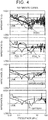
- FIGS. 4 to 6 each include four graphs.
- the graph at the top shows the frequency characteristics of the system impedance from the point of each of the target devices (including the high-voltage battery 4) along with the frequency characteristics of the LISN.
- the second graph shows the frequency characteristics of the system impedance from the point of each of the rear PCU 8 and the front PCU 12 along with the frequency characteristics of the LISN.
- the third graph shows the frequency characteristics of the system impedance from the point of the water heater 16 along with the frequency characteristics of the LISN.
- the graph at the bottom shows the frequency characteristics of the system impedance from the point of the high-voltage battery 4 along with the frequency characteristics of the LISN.
- FIG. 4 shows the frequency characteristics of the system impedance when the vehicle power supply system 2 does not include the ferrite cores. Focusing on the vicinity of 1 MHz that is the center of the AM band, the system impedance is lower than the impedance of the LISN in each of the rear PCU 8, the front PCU 12, the water heater 16, and the high-voltage battery 4. Further, the system impedance from the point of the first DC-DC converter 42 (denoted as DCDC in the graph) is also lower than the impedance of the LISN.
- FIG. 5 shows the frequency characteristics of the system impedance when the ferrite cores 50, 52, 54 are provided for the rear PCU 8, the front PCU 12, and the water heater 16.
- the system impedance of each of the rear PCU 8, the front PCU 12, and the water heater 16 in the AM band is higher than the impedance of the LISN.
- the system impedance from the point of the high-voltage battery 4 remains slightly lower than the impedance of the LISN, and the system impedance from the point of the first DC-DC converter 42 also remains lower than the impedance of the LISN.
- FIG. 6 further shows the frequency characteristics of the system impedance when the ferrite core 56 is also provided for the high-voltage battery 4.
- the system impedance of the high-voltage battery 4 in the vicinity of 1 MHz in the AM band is higher than the impedance of the LISN. Further, the system impedance of other devices including the first DC-DC converter 42 in the AM band increases to near the impedance of the LISN. Further, the variation of the system impedance in the AM band among the target devices (including the high-voltage battery 4) is settled within the range of about 20 ⁇ .
- the system impedance of some devices including the first DC-DC converter 42 in the AM band is not higher than the impedance of the LISN.
- adjustment of the shape and the material of each of the ferrite cores 50, 52, 54, 56 makes it possible to increase the system impedance in the AM band of all of the target devices to be higher than the impedance of the LISN, while the variation of the system impedance among the target devices is settled within an allowable range.
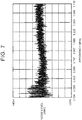
- FIG. 7 shows noise level-frequency characteristics before adjusting the shapes and the materials of the ferrite cores 50, 52, 54, 56.
- FIG. 8 shows the noise level-frequency characteristics after the shapes and the materials of the ferrite cores 50, 52, 54, 56 are adjusted. Reduction of the noise level in the AM band as a whole can be confirmed from a comparison of the two noise level-frequency characteristics as a result of adjusting the shapes and the materials of the ferrite cores 50, 52, 54, 56.
- the rear PCU 8, the front PCU 12, and the water heater 16 are regarded as the noise generators.
- any device having a switching element can be a noise generator. Therefore, the first DC-DC converter 42 and the second DC-DC converter 20 can also be the noise generators.
- what is important is to reduce the noise in the AM band as the entire vehicle power supply system 2, and the ferrite cores are not necessarily provided for all the noise generators. In the examples shown in FIGS. 4 to 8 , the noise in the AM band is reduced in the entire system even when the ferrite cores are not provided for the first DC-DC converter 42 and the second DC-DC converter 20.
Abstract
Description
- The invention relates to a vehicle power supply system.
- As a countermeasure against noise in a common mode, a technique is known that a noise filter in which a Y capacitor and an impedance element are combined is provided for a noise generator. Examples of the impedance element include ferrite cores and common mode choke coils. In an example disclosed in Japanese Unexamined Patent Application Publication No.
2019-047541 JP 2019-047541 A - One of the issues in the vehicle power supply system is to reduce noise in an amplitude modulation (AM) band (0.1 to 2 MHz), so-called radio noise. The vehicle power supply system is composed of a plurality of devices including a device that is a noise generation source. The technique described in
JP 2019-047541 A - The invention provides a vehicle power supply system capable of reducing noise in an AM band.
- A vehicle power supply system according to an aspect of the invention includes: a power storage device; a plurality of devices including a plurality of noise generators; and a power distribution circuit that connects the power storage device and the devices. Each of the noise generators is connected to the power distribution circuit via a noise filter. The noise filter includes a first impedance element and a Y capacitor that is provided closer to the noise generators than the first impedance element. The first impedance element provided for each of the noise generators is an impedance element with a shape and a material that increase a first system impedance of each of the devices to be higher than a predetermined lower limit impedance at least in an amplitude modulation band. The first system impedance is an impedance on a power distribution circuit side with respect to a connection portion of each of the devices with the power distribution circuit.
- With the vehicle power supply system according to the aspect of the invention, the shape and the material of each impedance element are adjusted such that the system impedance is higher than the predetermined lower limit impedance in each of the devices at least in the AM band. Therefore, the noise can be reduced in the AM band as the entire vehicle power supply system. In the vehicle power supply system according to the aspect of the invention, the first impedance element may be an impedance element with a shape and a material that settle a variation of the first system impedance among the devices within a predetermined allowable range. With the vehicle power supply system according to the aspect of the invention, entry of the noise into the device having lower system impedance than that of the other devices can be suppressed.
- In the vehicle power supply system according to the aspect of the invention, the power storage device may be connected to the power distribution circuit via a second impedance element. The second impedance element provided for the power storage device may be an impedance element with a shape and a material that increase the second system impedance to be higher than the predetermined lower limit impedance at least in the AM band in the power storage device. The second system impedance may be an impedance on a power distribution circuit side with respect to a connection portion of the power storage device with the power distribution circuit. With the vehicle power supply system according to the aspect of the invention, the noise in the AM band can be reduced as the entire vehicle power supply system even when the power storage device is one of noise generation sources. In the vehicle power supply system according to the aspect of the invention, the first impedance element and the second impedance element may be impedance elements with shapes and materials that settle a variation of the first system impedance and the second system impedance among the devices and the power storage device within a predetermined allowable range. With the vehicle power supply system according to the aspect of the invention, entry of the noise into the device having lower system impedance than that of the other devices or the power storage device can be suppressed.
- In the vehicle power supply system according to the aspect of the invention, the predetermined lower limit impedance may be an impedance determined based on impedance-frequency characteristics of a line impedance stabilization network. In the vehicle power supply system according to the aspect of the invention, the first impedance element and the second impedance element may be a ferrite core. In the vehicle power supply system according to the aspect of the invention, at least one of the noise generators may be an inverter including a switching element. In the vehicle power supply system according to the aspect of the invention, at least one of the devices may be a direct current-direct current (DC-DC) converter.
- As described above, with the vehicle power supply system according to the aspect of the invention, the noise in the AM band can be reduced as the entire vehicle power supply system.
- Features, advantages, and technical and industrial significance of exemplary embodiments of the invention will be described below with reference to the accompanying drawings, in which like signs denote like elements, and wherein:
-
FIG. 1 is a diagram showing a configuration of a vehicle power supply system according to an embodiment of the invention; -
FIG. 2 is a circuit diagram showing an equivalent circuit of a power control unit (PCU) ; -
FIG. 3 is a diagram showing a procedure for adjusting a shape and a material of a ferrite core; -
FIG. 4 is a diagram showing frequency characteristics of a system impedance when no ferrite cores are provided; -
FIG. 5 is a diagram showing frequency characteristics of a system impedance when the ferrite cores are provided for the PCU and a water heater; -
FIG. 6 is a diagram showing frequency characteristics of a system impedance when the ferrite cores are provided for the PCU, the water heater, and a battery; -
FIG. 7 shows noise level-frequency characteristics before adjusting the shapes and the materials of the ferrite cores; and -
FIG. 8 shows noise level-frequency characteristics after the shapes and the materials of the ferrite cores are adjusted. - Embodiments of the invention will be described below with reference to the drawings. However, in the following embodiments, when the number, a quantity, an amount, or a range of each element, for example, is mentioned, the invention is not limited to the mentioned number, etc., unless otherwise specified or except for the case where the number is obviously limited to the number mentioned in the embodiments in principle. Further, configurations, etc. that will be described in the following embodiments are not necessarily essential to the invention, unless otherwise specified or except for the case where configurations are obviously limited to the configurations mentioned in the embodiments in principle.
-
FIG. 1 shows a configuration of a vehicle power supply system according to an embodiment. A vehiclepower supply system 2 according to the embodiment is a power supply system for an electric vehicle. However, the vehiclepower supply system 2 may also be applied to a hybrid vehicle equipped with an engine, in addition to a pure electric vehicle not equipped with the engine. - The electric vehicle to which the vehicle
power supply system 2 is applied includes arear motor generator 10 for driving rear wheels and afront motor generator 14 for driving front wheels. Hereinafter, the motor generator is referred to as an MG. TheMGs MGs - The vehicle
power supply system 2 includes a high-voltage battery 4 configured to be chargeable and dischargeable. The electric power for driving theMGs voltage battery 4. Further, the high-voltage battery 4 is charged with the electric power generated by theMGs voltage battery 4 is a power storage device including a secondary battery such as a lithium ion battery or a nickel metal hydride battery. The lithium ion secondary battery may be a general lithium ion secondary battery having a liquid electrolyte, or an all-solid-state battery using a solid electrolyte. The high-voltage battery 4 may also be replaced with a power storage device including a power storage element such as a capacitor. - The vehicle
power supply system 2 includes apower distribution unit 6 that supplies the electric power stored in the high-voltage battery 4 to a plurality of devices. Thepower distribution unit 6 includes abranch box 40 for connecting the devices to the high-voltage battery 4. - The
branch box 40 is connected to the high-voltage battery 4 via a system main relay (not shown). Thebranch box 40 includes a first power control unit 8, a secondpower control unit 12, awater heater 16, anair conditioner 18, a first direct current-direct current (DC-DC)converter 42, a second DC-DC converter 20, and a DCpower supply inlet 24 that are connected in parallel by a pair of power lines. Thebranch box 40 and the power lines connecting thebranch box 40 and the devices constitute a power distribution circuit for connecting the devices and the high-voltage battery 4. Hereinafter, the power control unit will be referred to as a PCU. - The
PCUs 8, 12 include a plurality of power cards stacked on each other with a cooler interposed therebetween. Each of the power cards includes a single package of an insulated gate bipolar transistor (IGBT) and a diode constituting the inverter. The PCU (rear PCU) 8 is provided between the high-voltage battery 4 and the MG (rear MG) 10. The PCU (front PCU) 12 is provided between the high-voltage battery 4 and the MG (front MG) 14. ThePCUs 8, 12 control the driving force generated by theMGs voltage battery 4. The electric power generated by theMGs voltage battery 4 via thePCUs 8, 12. - The
water heater 16 is connected to thebranch box 40 via afuse 30. Thewater heater 16 operates with the electric power supplied from the high-voltage battery 4 to heat water to generate hot water. The hot water generated by thewater heater 16 is used for, for example, heating a cabin of the vehicle in winter. Thewater heater 16 is, for example, a positive temperature coefficient (PTC) heater. Energization to the water heater is controlled using a pulse width modulation (PWM) method based on a control signal from an electronic control unit (ECU), which is not shown. - The
air conditioner 18 is connected to thebranch box 40 via afuse 32. Theair conditioner 18 includes an electric compressor (not shown). The compressor operates with the electric power supplied from the high-voltage battery 4. Theair conditioner 18 adjusts the temperature inside the cabin of the vehicle based on a control signal from an ECU (not shown). - The first DC-
DC converter 42 is built in thepower distribution unit 6. The first DC-DC converter 42 is a large current output converter having a rated output current of, for example, 150 A. The first DC-DC converter 42 is connected to a low voltage battery (not shown) and is configured to step down the electric power received from the high-voltage battery 4 to a voltage level of the low-voltage battery. - The second DC-
DC converter 20 is connected to thebranch box 40 via afuse 34. The rated output current of the second DC-DC converter 20 is, for example, 50 A. The second DC-DC converter 20 is connected to an alternate current (AC) 100V inverter 22 and is configured to step down the electric power received from the high-voltage battery 4 to an input voltage level of the AC 100V inverter 22. - The DC
power supply inlet 24 is a power receiving unit to which a connector of a DC charging cable (not shown) is connected. The DC charging cable is connected to a DC power supply (not shown). The DCpower supply inlet 24 is connected to thebranch box 40 via DC relays 44, 46 built in thepower distribution unit 6. The DC relays 44, 46 are turned on by an ECU (not shown) when external charging by the DC power supply is executed. - The
power distribution unit 6 includes a built-inAC charger 48. An ACpower supply inlet 26 installed outside thepower distribution unit 6 is connected to theAC charger 48. The ACpower supply inlet 26 is a power receiving unit to which a connector of an AC charging cable (not shown) is connected. The AC charging cable is connected to an AC power supply (not shown). - The
AC charger 48 includes an AC-DC converter that converts AC power received from the AC power supply into DC, and a DC-DC converter that converts the output of the AC-DC converter to the voltage level of the high-voltage battery 4. TheAC charger 48 is not connected to thebranch box 40, and is directly connected to the high-voltage battery 4 via a charging relay (not shown). The charging relay is turned on by an ECU (not shown) when external charging by the AC power supply is executed. - In addition to the configuration above, the vehicle
power supply system 2 includes impedance elements at key points. In the embodiment,ferrite cores ferrite core 50 is provided in the power line connecting the rear PCU 8 and thebranch box 40. Theferrite core 52 is provided in the power line connecting thefront PCU 12 and thebranch box 40. Theferrite core 54 is provided in the power line connecting thewater heater 16 and thebranch box 40. In the embodiment, theferrite cores ferrite core 56 is provided in the power line connecting the high-voltage battery 4 and thebranch box 40. In the embodiment, theferrite core 56 may be regarded as an example of a second impedance element. - The rear PCU 8, the
front PCU 12, and thewater heater 16 for which theferrite cores voltage battery 4 for which theferrite core 56 is provided also has a noise generation source inside. Theferrite cores power supply system 2 to the outside, particularly noise in the common mode, by increasing a system impedance that will be described later. The layout positions of theferrite cores FIG. 1 are examples. Theferrite cores power distribution unit 6. - Next, details of noise reduction measures adopted in the vehicle
power supply system 2 will be described with reference toFIG. 2. FIG. 2 is a circuit diagram showing an equivalent circuit of the PCU. Here, the equivalent circuit of thefront PCU 12 is taken as an example. However, the equivalent circuit of the rear PCU 8 can also be represented by the same circuit diagram. Further, the equivalent circuits of other noise generators can be represented by circuit diagrams similar to the above circuit. - The
front PCU 12 includes a booster circuit (not shown) andinverters inverters MG 14 shown inFIG. 1 as a motor, and the other inverter (the inverter 82) operates theMG 14 as a generator. The noise is generated from theinverters inverters - The noise emitted from each noise generator of the vehicle
power supply system 2 along the power line includes the noise in the common mode. In the vehiclepower supply system 2, a noise filter for reducing the noise in the common mode is provided for each noise generator. The noise filter includes a Y capacitor provided on the power distribution circuit side and the ferrite core above provided on the power distribution circuit side. Anoise filter 60 is also provided for thefront PCU 12. - The
noise filter 60 for thefront PCU 12 includes aY capacitor 62 and theferrite core 52. TheY capacitor 62 is provided on theinverters ferrite core 52. TheY capacitor 62 includes twocapacitors 63a, 63b corresponding to the pair of power lines. Thecapacitors 63a, 63b are grounded to a housing of thefront PCU 12. - As represented by the equivalent circuit, a power line of the booster circuit (not shown) and the cooler for cooling the power card are connected via a
parasitic capacitance 70. Further, a stable portion that is a portion between the booster circuit and theinverters parasitic capacitances inverters MG 14 and the cooler are connected viaparasitic capacitances front PCU 12. - With the
Y capacitor 62 provided, common mode current flowing out of theinverters front PCU 12 via theY capacitor 62, and returns to theinverters parasitic capacitances Y capacitor 62 provides a common mode noise feedback path for theinverters Y capacitor 62 has an effect of lowering the impedance in a specific frequency range. - The
ferrite core 52 that is an impedance element has a role of increasing the impedance lowered due to the installation of theY capacitor 62. What is important here is that theferrite core 52 installed for thefront PCU 12 has the effect of increasing the impedance of other devices and the high-voltage battery 4 connected to theferrite core 52 via thebranch box 40. Similarly, theferrite cores voltage battery 4 also have the effect of increasing the impedance of thefront PCU 12. - The impedance on the power distribution circuit side with respect to a connection portion of the devices connected to the power distribution circuit or the high-
voltage battery 4 with the power distribution circuit is defined as the system impedance. Examples of the target device of the system impedance include the rear PCU 8, thefront PCU 12, thewater heater 16, theair conditioner 18, the first DC-DC converter 42, and the second DC-DC converter 20. The system impedance value varies from device to device. For example, the system impedance value from the point of thefront PCU 12 is different from the system impedance value from the point of the first DC-DC converter 42, and is also different from the system impedance value from the point of the high-voltage battery 4. When the system impedance can be increased in each of the devices connected to the power distribution circuit and the high-voltage battery 4, the noise can be reduced in the entire system of the vehiclepower supply system 2. - However, it is difficult and impractical to reduce the noise in all the frequency ranges. Further, even when the noise is reduced with focusing on a specific frequency range, it is not easy to bring the noise close to zero. The noise that is preferentially reduced in the vehicle is the noise in the AM band, that is, the radio noise. Therefore, in the embodiment, the
ferrite cores - More specifically, the
ferrite cores voltage battery 4 becomes higher than a predetermined lower limit impedance at least in the AM band. As the lower limit impedance set with respect to the system impedance, for example, the impedance in the AM band determined based on impedance-frequency characteristics of a line impedance stabilization network (LISN) may be used. - Further, in the embodiment, the
ferrite cores voltage battery 4 is settled within a predetermined allowable range. The range of the system impedance in which the variation is allowed is, for example, 20 Ω. Reduction of the variation in the system impedance between the devices and the high-voltage battery 4 makes it possible to suppress entry of the noise to a specific device having a low system impedance. - Design of the
ferrite cores ferrite cores ferrite cores ferrite cores - Next, the procedure for adjusting the shapes and materials of the
ferrite cores FIG. 3 . First, in step S1, a device of which system impedance is to be measured is selected from the target devices (including the high-voltage battery 4). In step S2, the shapes and materials of theferrite cores ferrite cores - The processing from steps S2 to S4 will be described more specifically as follows. First, the ferrite material is determined for one of the ferrite cores. Examples of selectable ferrite materials include HF40, HF57, and HF70. Determination of the ferrite material further determines the magnetic permeability based on the magnetic permeability-frequency characteristics unique to the ferrite material. Next, the core shape of the ferrite core is tentatively determined. Once the core shape and the magnetic permeability are determined, the impedance, the inductance, and the reactance that are the characteristic values of the ferrite core are quantified. The same processing is executed for other ferrite cores. The system impedance is then calculated based on the impedance, the inductance, and the reactance of each of the ferrite cores. When the calculated value of the system impedance is equal to or less than the lower limit value, the core shape is tentatively determined again without changing the ferrite material. When the calculated value of the system impedance becomes larger than the lower limit value as a result of optimization by fine-tuning the core shape as described above, the core shape tentatively determined at that time is determined as a formal core shape. On the other hand, when the calculated value of the system impedance does not exceed the lower limit value, the ferrite material is changed and the above processing is repeated.
- When the system impedance becomes larger than the lower limit value, the processing proceeds to step S5. In step S5, whether adjustment of the system impedance is completed for all the target devices (including the high-voltage battery 4) is determined. When adjustment for all the target devices is not completed, the processing returns to step S1, and the devices of which system impedance is calculated are changed. The above processing is repeated until adjustment of the system impedance is completed for all the target devices.
- In the above procedure, the shapes and the materials of the
ferrite cores ferrite cores ferrite cores power supply system 2, and the system impedance may be measured using an impedance analyzer. - Finally, the results of adjusting the shapes and the materials of the
ferrite cores FIGS. 4 to 8 .FIGS. 4 to 6 each include four graphs. The graph at the top shows the frequency characteristics of the system impedance from the point of each of the target devices (including the high-voltage battery 4) along with the frequency characteristics of the LISN. The second graph shows the frequency characteristics of the system impedance from the point of each of the rear PCU 8 and thefront PCU 12 along with the frequency characteristics of the LISN. The third graph shows the frequency characteristics of the system impedance from the point of thewater heater 16 along with the frequency characteristics of the LISN. The graph at the bottom shows the frequency characteristics of the system impedance from the point of the high-voltage battery 4 along with the frequency characteristics of the LISN. -
FIG. 4 shows the frequency characteristics of the system impedance when the vehiclepower supply system 2 does not include the ferrite cores. Focusing on the vicinity of 1 MHz that is the center of the AM band, the system impedance is lower than the impedance of the LISN in each of the rear PCU 8, thefront PCU 12, thewater heater 16, and the high-voltage battery 4. Further, the system impedance from the point of the first DC-DC converter 42 (denoted as DCDC in the graph) is also lower than the impedance of the LISN. -
FIG. 5 shows the frequency characteristics of the system impedance when theferrite cores front PCU 12, and thewater heater 16. The system impedance of each of the rear PCU 8, thefront PCU 12, and thewater heater 16 in the AM band is higher than the impedance of the LISN. However, the system impedance from the point of the high-voltage battery 4 remains slightly lower than the impedance of the LISN, and the system impedance from the point of the first DC-DC converter 42 also remains lower than the impedance of the LISN. -
FIG. 6 further shows the frequency characteristics of the system impedance when theferrite core 56 is also provided for the high-voltage battery 4. The system impedance of the high-voltage battery 4 in the vicinity of 1 MHz in the AM band is higher than the impedance of the LISN. Further, the system impedance of other devices including the first DC-DC converter 42 in the AM band increases to near the impedance of the LISN. Further, the variation of the system impedance in the AM band among the target devices (including the high-voltage battery 4) is settled within the range of about 20 Ω. - In the graph shown in
FIG. 6 , the system impedance of some devices including the first DC-DC converter 42 in the AM band is not higher than the impedance of the LISN. However, adjustment of the shape and the material of each of theferrite cores -
FIG. 7 shows noise level-frequency characteristics before adjusting the shapes and the materials of theferrite cores FIG. 8 shows the noise level-frequency characteristics after the shapes and the materials of theferrite cores ferrite cores - In the embodiment, the rear PCU 8, the
front PCU 12, and thewater heater 16 are regarded as the noise generators. However, any device having a switching element can be a noise generator. Therefore, the first DC-DC converter 42 and the second DC-DC converter 20 can also be the noise generators. However, what is important is to reduce the noise in the AM band as the entire vehiclepower supply system 2, and the ferrite cores are not necessarily provided for all the noise generators. In the examples shown inFIGS. 4 to 8 , the noise in the AM band is reduced in the entire system even when the ferrite cores are not provided for the first DC-DC converter 42 and the second DC-DC converter 20.
Claims (8)
- A vehicle power supply system (2) comprising:a power storage device (4);a plurality of devices (8, 12, 16, 20, 42) including a plurality of noise generators; anda power distribution circuit that connects the power storage device (4) and the devices (8, 12, 16, 20, 42), whereineach of the noise generators is connected to the power distribution circuit via a noise filter;the noise filter includes a first impedance element and a Y capacitor that is provided closer to the noise generators than the first impedance element; andthe first impedance element provided for each of the noise generators is an impedance element with a shape and a material that increase a first system impedance of each of the devices (8, 12, 16, 20, 42) to be higher than a predetermined lower limit impedance at least in an amplitude modulation band, and the first system impedance is an impedance on a power distribution circuit side with respect to a connection portion of each of the devices (8, 12, 16, 20, 42) with the power distribution circuit.
- The vehicle power supply system (2) according to claim 1, wherein:the power storage device (4) is connected to the power distribution circuit via a second impedance element; andthe second impedance element provided for the power storage device (4) is an impedance element with a shape and a material that increase a second system impedance to be higher than the predetermined lower limit impedance at least in the amplitude modulation band in the power storage device, and the second system impedance is an impedance on a power distribution circuit side with respect to a connection portion of the power storage device (4) with the power distribution circuit.
- The vehicle power supply system (2) according to claim 1, wherein the first impedance element is an impedance element with a shape and a material that settle a variation of the first system impedance among the devices (8, 12, 16, 20, 42) within a predetermined allowable range.
- The vehicle power supply system (2) according to claim 2, wherein the first impedance element and the second impedance element are impedance elements with shapes and materials that settle a variation of the first system impedance and the second system impedance among the devices (8, 12, 16, 20, 42) and the power storage device (4) within a predetermined allowable range.
- The vehicle power supply system (2) according to any of claims 1 to 4, wherein the predetermined lower limit impedance is an impedance determined based on impedance-frequency characteristics of a line impedance stabilization network.
- The vehicle power supply system (2) according to any of claims 1 to 5, wherein the first impedance element and a second impedance element are ferrite cores (50, 52, 54, 56).
- The vehicle power supply system (2) according to any of claims 1 to 6, wherein at least one of the noise generators is an inverter (80, 82) including a switching element.
- The vehicle power supply system (2) according to any one of claims 1 to 7, wherein at least one of the devices (8, 12, 16, 20, 42) is a direct current-direct current converter.
Applications Claiming Priority (1)
| Application Number | Priority Date | Filing Date | Title |
|---|---|---|---|
| JP2020040095A JP7363599B2 (en) | 2020-03-09 | 2020-03-09 | Vehicle power system |
Publications (1)
| Publication Number | Publication Date |
|---|---|
| EP3878700A1 true EP3878700A1 (en) | 2021-09-15 |
Family
ID=74856685
Family Applications (1)
| Application Number | Title | Priority Date | Filing Date |
|---|---|---|---|
| EP21160334.5A Withdrawn EP3878700A1 (en) | 2020-03-09 | 2021-03-02 | Vehicle power supply system |
Country Status (4)
| Country | Link |
|---|---|
| US (1) | US11312245B2 (en) |
| EP (1) | EP3878700A1 (en) |
| JP (1) | JP7363599B2 (en) |
| CN (1) | CN113370805A (en) |
Cited By (1)
| Publication number | Priority date | Publication date | Assignee | Title |
|---|---|---|---|---|
| WO2023083765A1 (en) * | 2021-11-09 | 2023-05-19 | Mercedes-Benz Group AG | Component assembly for an electric high-voltage on-board power system of a vehicle |
Citations (1)
| Publication number | Priority date | Publication date | Assignee | Title |
|---|---|---|---|---|
| JP2019047541A (en) | 2017-08-29 | 2019-03-22 | ダイキン工業株式会社 | Power conversion system |
Family Cites Families (18)
| Publication number | Priority date | Publication date | Assignee | Title |
|---|---|---|---|---|
| JPH0265516A (en) * | 1988-08-31 | 1990-03-06 | Toshiba Corp | Line filter |
| JPH056824A (en) * | 1991-06-27 | 1993-01-14 | Pilot Precision Co Ltd | Inductor element |
| JP3195588B2 (en) | 1999-02-23 | 2001-08-06 | 株式会社エヌ・ティ・ティ・データ | Noise filter |
| JP2006332475A (en) | 2005-05-30 | 2006-12-07 | Auto Network Gijutsu Kenkyusho:Kk | Ferrite core for wide frequency band |
| JP4630367B2 (en) * | 2008-11-25 | 2011-02-09 | 本田技研工業株式会社 | High-voltage equipment unit for vehicles |
| JP5402471B2 (en) * | 2008-12-05 | 2014-01-29 | ソニー株式会社 | Power supply, power cable, and receiver |
| US9166488B2 (en) * | 2009-10-30 | 2015-10-20 | Delta Electronics Inc. | Method and apparatus for resetting a resonant converter |
| GB201014384D0 (en) * | 2010-08-27 | 2010-10-13 | Imp Innovations Ltd | Battery monitoring in electric vehicles, hybrid electric vehicles and other applications |
| CN110091733B (en) * | 2013-06-11 | 2022-11-22 | 松下知识产权经营株式会社 | Charging device and vehicle |
| WO2015104936A1 (en) | 2014-01-07 | 2015-07-16 | 株式会社村田製作所 | Ferrite core and noise filter |
| JP6388151B2 (en) * | 2014-07-18 | 2018-09-12 | パナソニックIpマネジメント株式会社 | Power supply |
| US10295213B2 (en) * | 2015-06-26 | 2019-05-21 | Mitsubishi Electric Corporation | Air conditioning apparatus |
| JP6597446B2 (en) * | 2016-03-28 | 2019-10-30 | 株式会社豊田自動織機 | In-vehicle electric compressor |
| JP6643972B2 (en) | 2016-12-13 | 2020-02-12 | 日立オートモティブシステムズ株式会社 | Bus bar structure and power conversion device using the same |
| JP6858070B2 (en) * | 2017-05-08 | 2021-04-14 | 三星電子株式会社Samsung Electronics Co.,Ltd. | Conductive noise suppression device, power conversion device and motor device |
| JP6980630B2 (en) * | 2018-09-25 | 2021-12-15 | 日立Astemo株式会社 | High voltage filter and power converter |
| JP2020088888A (en) * | 2018-11-15 | 2020-06-04 | 株式会社日立製作所 | Voltage filter and power conversion device |
| US11874423B2 (en) * | 2019-10-25 | 2024-01-16 | Witricity Corporation | Circuit for object detection and vehicle position determination |
-
2020
- 2020-03-09 JP JP2020040095A patent/JP7363599B2/en active Active
-
2021
- 2021-03-01 US US17/188,208 patent/US11312245B2/en active Active
- 2021-03-02 CN CN202110229487.0A patent/CN113370805A/en active Pending
- 2021-03-02 EP EP21160334.5A patent/EP3878700A1/en not_active Withdrawn
Patent Citations (1)
| Publication number | Priority date | Publication date | Assignee | Title |
|---|---|---|---|---|
| JP2019047541A (en) | 2017-08-29 | 2019-03-22 | ダイキン工業株式会社 | Power conversion system |
Cited By (1)
| Publication number | Priority date | Publication date | Assignee | Title |
|---|---|---|---|---|
| WO2023083765A1 (en) * | 2021-11-09 | 2023-05-19 | Mercedes-Benz Group AG | Component assembly for an electric high-voltage on-board power system of a vehicle |
Also Published As
| Publication number | Publication date |
|---|---|
| CN113370805A (en) | 2021-09-10 |
| US20210276431A1 (en) | 2021-09-09 |
| US11312245B2 (en) | 2022-04-26 |
| JP2021141545A (en) | 2021-09-16 |
| JP7363599B2 (en) | 2023-10-18 |
Similar Documents
| Publication | Publication Date | Title |
|---|---|---|
| Rivera et al. | Electric vehicle charging infrastructure: From grid to battery | |
| CN107791855B (en) | Method and apparatus for controlling on-vehicle charger | |
| KR101684064B1 (en) | Charging system of electric vehicle | |
| Onar et al. | Vehicular integration of wireless power transfer systems and hardware interoperability case studies | |
| Guo et al. | Development of an 85-kW bidirectional quasi-Z-source inverter with DC-link feed-forward compensation for electric vehicle applications | |
| KR102419697B1 (en) | A storage battery charging device for a vehicle, a method of operating an onboard storage battery charging device, a high voltage vehicle electrical system, and use of the storage battery charging device | |
| Kisacikoglu et al. | Reactive power operation analysis of a single-phase EV/PHEV bidirectional battery charger | |
| US9873341B2 (en) | Transformerless, current-isolated onboard charger with solid-state switching controls | |
| CN110289669B (en) | AC charging of intelligent battery | |
| KR20190010786A (en) | Electric vehicle | |
| US11296533B2 (en) | Vehicle power supply device | |
| US20170028855A1 (en) | Device for charging a battery of a motor vehicle on the basis of a single-phase power supply network, and method of controlling the device | |
| JP2015104310A (en) | Apparatus for rapid charging using onboard power electronics and method of manufacturing the same | |
| US20220224236A1 (en) | Magnetic integration of three-phase resonant converter and accessory power supply | |
| KR20190118084A (en) | Power converting system for vehicle | |
| Zeng et al. | High power density Z-source resonant wireless charger with line frequency sinusoidal charging | |
| EP3878700A1 (en) | Vehicle power supply system | |
| Viana et al. | Integrated transformerless EV charger with symmetrical modulation | |
| CN112172509B (en) | Four-wheel drive vehicle | |
| Tran et al. | An on-board V2X electric vehicle charger based on amorphous alloy high-frequency magnetic-link and SiC power devices | |
| Bertoluzzo et al. | Design considerations for fast AC battery chargers | |
| Heo et al. | Integration of OBC and LDC using adaptive DC link voltage | |
| Chinthavali et al. | All-SiC inductively coupled charger with integrated plug-in and boost functionalities for PEV applications | |
| US11949330B2 (en) | Integrated power conversion topology for electric vehicles | |
| Moradewicz et al. | Bidirectional inductive contactless energy transfer system topology for Electric Vehicles |
Legal Events
| Date | Code | Title | Description |
|---|---|---|---|
| PUAI | Public reference made under article 153(3) epc to a published international application that has entered the european phase |
Free format text: ORIGINAL CODE: 0009012 |
|
| STAA | Information on the status of an ep patent application or granted ep patent |
Free format text: STATUS: REQUEST FOR EXAMINATION WAS MADE |
|
| 17P | Request for examination filed |
Effective date: 20210302 |
|
| AK | Designated contracting states |
Kind code of ref document: A1 Designated state(s): AL AT BE BG CH CY CZ DE DK EE ES FI FR GB GR HR HU IE IS IT LI LT LU LV MC MK MT NL NO PL PT RO RS SE SI SK SM TR |
|
| GRAP | Despatch of communication of intention to grant a patent |
Free format text: ORIGINAL CODE: EPIDOSNIGR1 |
|
| STAA | Information on the status of an ep patent application or granted ep patent |
Free format text: STATUS: GRANT OF PATENT IS INTENDED |
|
| RIC1 | Information provided on ipc code assigned before grant |
Ipc: H02M 1/44 20070101ALI20220614BHEP Ipc: H02M 1/14 20060101ALI20220614BHEP Ipc: B60R 16/03 20060101AFI20220614BHEP |
|
| INTG | Intention to grant announced |
Effective date: 20220711 |
|
| STAA | Information on the status of an ep patent application or granted ep patent |
Free format text: STATUS: THE APPLICATION IS DEEMED TO BE WITHDRAWN |
|
| 18D | Application deemed to be withdrawn |
Effective date: 20221122 |