EP3878572A1 - Mold for continuous steel casting and continuous steel casting method - Google Patents
Mold for continuous steel casting and continuous steel casting method Download PDFInfo
- Publication number
- EP3878572A1 EP3878572A1 EP19882667.9A EP19882667A EP3878572A1 EP 3878572 A1 EP3878572 A1 EP 3878572A1 EP 19882667 A EP19882667 A EP 19882667A EP 3878572 A1 EP3878572 A1 EP 3878572A1
- Authority
- EP
- European Patent Office
- Prior art keywords
- mold
- dissimilar material
- cooling water
- filled
- steel casting
- Prior art date
- Legal status (The legal status is an assumption and is not a legal conclusion. Google has not performed a legal analysis and makes no representation as to the accuracy of the status listed.)
- Granted
Links
Images

Classifications
-
- B—PERFORMING OPERATIONS; TRANSPORTING
- B22—CASTING; POWDER METALLURGY
- B22D—CASTING OF METALS; CASTING OF OTHER SUBSTANCES BY THE SAME PROCESSES OR DEVICES
- B22D11/00—Continuous casting of metals, i.e. casting in indefinite lengths
- B22D11/08—Accessories for starting the casting procedure
-
- B—PERFORMING OPERATIONS; TRANSPORTING
- B22—CASTING; POWDER METALLURGY
- B22D—CASTING OF METALS; CASTING OF OTHER SUBSTANCES BY THE SAME PROCESSES OR DEVICES
- B22D11/00—Continuous casting of metals, i.e. casting in indefinite lengths
- B22D11/04—Continuous casting of metals, i.e. casting in indefinite lengths into open-ended moulds
- B22D11/055—Cooling the moulds
-
- B—PERFORMING OPERATIONS; TRANSPORTING
- B22—CASTING; POWDER METALLURGY
- B22D—CASTING OF METALS; CASTING OF OTHER SUBSTANCES BY THE SAME PROCESSES OR DEVICES
- B22D11/00—Continuous casting of metals, i.e. casting in indefinite lengths
- B22D11/04—Continuous casting of metals, i.e. casting in indefinite lengths into open-ended moulds
-
- B—PERFORMING OPERATIONS; TRANSPORTING
- B22—CASTING; POWDER METALLURGY
- B22D—CASTING OF METALS; CASTING OF OTHER SUBSTANCES BY THE SAME PROCESSES OR DEVICES
- B22D11/00—Continuous casting of metals, i.e. casting in indefinite lengths
- B22D11/04—Continuous casting of metals, i.e. casting in indefinite lengths into open-ended moulds
- B22D11/0401—Moulds provided with a feed head
-
- B—PERFORMING OPERATIONS; TRANSPORTING
- B22—CASTING; POWDER METALLURGY
- B22D—CASTING OF METALS; CASTING OF OTHER SUBSTANCES BY THE SAME PROCESSES OR DEVICES
- B22D11/00—Continuous casting of metals, i.e. casting in indefinite lengths
- B22D11/04—Continuous casting of metals, i.e. casting in indefinite lengths into open-ended moulds
- B22D11/059—Mould materials or platings
Definitions
- the present invention relates to a mold for continuous casting that can prevent surface cracking in a strand caused by uneven cooling of a solidifying shell and can be used more times than conventional molds.
- the invention also relates to a continuous steel casting method using the mold for continuous casting.
- the thickness of the solidifying shell may be nonuniform in the strand withdrawal direction and the width direction of the mold.
- Stress due to shrinkage or deformation of the solidifying shell itself acts on the solidifying shell. This stress concentrates on a thin-walled portion of the solidifying shell, and the stress concentration causes cracks to occur on the surface of the solidifying shell in the early stage of solidification. These surface cracks grow due to subsequent thermal stress and external forces such as bending stress and levelling stress in the continuous casting machine, and larger surface cracks are thereby formed.
- the cracks on the surface of the strand become surface defects of a steel product in the subsequent hot-rolling step. Therefore, to prevent the occurrence of the defects on the surface of the steel product, it is necessary to hot-scarf or grind the surface of the slab to remove the surface cracks in the slab.
- Patent Literature 1 proposes a mold for continuous casting that has a plurality of dissimilar material-filled portions formed independently on inner wall surfaces of the mold and having a thermal conductivity different from that of a copper alloy forming mold plates (referred to also as "copper mold plates"). It is stated in Patent Literature 1 that the use of the mold can effectively prevent surface cracking in the strand due to uneven cooling of the solidifying shell in the early stage of solidification. In particular, it is stated that surface cracking in the strand due to unevenness in the thickness of the solidifying shell caused by transformation from ⁇ iron to y iron in medium carbon steel undergoing the peritectic reaction can be effectively prevented.
- Patent Literature 1 In the mold for continuous steel casting described in Patent Literature 1, the dissimilar material-filled portions formed of a material different from the material of the mold plates are formed in the mold plates. Therefore, the thermal expansion coefficient of the mold plates differs from the thermal expansion coefficient of the dissimilar material-filled portions, and thermal stress is likely to concentrate on boundary portions therebetween, so that cracks are likely to occur on the surface of the mold. It is stated in Patent Literature 1 that it is preferable to provide a plating layer covering the dissimilar material-filled portions on the inner wall surfaces of the mold for the purpose of preventing cracks on the surface of the mold caused by thermal history and that this can extend the service life of the mold.
- the present invention has been made in view of the above circumstances, and it is an object to provide a mold for continuous casting that has dissimilar material-filled portions formed therein and can be used significantly more times than conventional molds. It is another object to provide a continuous steel casting method that uses the mold for continuous casting.
- the water stream disturbing portion that disturbs the water stream and increases the surface area of the cooling water channel is formed in a portion of the cooling water channel that corresponds to the region in which the dissimilar material-filled portion is formed. Therefore, in this portion of the cooling water channel, the heat transfer coefficient between the water stream and the cooling water channel is large, and the amount of convective heat transfer is increased, so that heat in the mold plate in the region in which the dissimilar material-filled portion is formed can be effectively removed.
- the thermal stress generated in the boundary portion between the mold plate and the dissimilar material-filled portion can be effectively reduced.
- the occurrence of surface cracking in a strand of the steel type undergoing the peritectic reaction is prevented, and the number of times the mold having the dissimilar material-filled portion formed therein can be used can be increased, i.e., the service life of the mold can be extended.
- a strand including the solidifying shell as its outer shell and the unsolidified molten steel 4 inside the solidifying shell is continuously withdrawn from the mold 1 in a strand withdrawal direction A, i.e., a vertically downward direction, to thereby produce a steel slab.
- the mold plates are in contact with the molten steel 4 and the high-temperature strand. Therefore, the surface temperature of the mold plates (the temperature on the side in contact with the molten steel) increases and is highest near the position of a meniscus M (the top surface of the molten steel in the mold) in the mold.
- the position of the meniscus M is indicated by a dash-dot line.
- a plurality of circular recesses are formed on the front surface of the mold plate 21, and the circular recesses are filled with the dissimilar material to form a plurality of independent dissimilar material-charged portions 22.
- the dissimilar material-charged portions 22 are arranged regularly such that the heat flux from the mold inner wall surface to the cooling water channels varies periodically on the mold inner wall surface.
- the thermal resistance of the mold plate 21 in the strand withdrawal direction A in the region including the vicinity of the meniscus M and the mold width direction B increases and decreases regularly and periodically.
- the heat flux in the vicinity of the meniscus M i.e., the heat flux from the solidifying shell to the mold plate 21 in the early stage of solidification, increases and decreases regularly and periodically.
- the regular and periodic increase and decrease of the heat flux reduces stress generated by transformation from ⁇ iron to y iron and thermal stress, so that the deformation of the solidifying shell caused by these stresses decreases.
- the shape of the recesses on the front surface of the mold plate 21 may not be perfect circular (referred to as “circular recesses”) and may be quasi-circular (referred to as “quasi-circular recesses”).
- the quasi-circular shape is a shape with no sharp corners such as an elliptical shape or a square or rectangular shape with circular or elliptical corners. Moreover, a petal-like shape may be used.
- the thermal conductivity of the dissimilar material is preferably 80% or less or 125% or more of the thermal conductivity of the mold plates formed in the mold long sides 2 and the mold short sides 3.
- the thermal conductivity of the dissimilar material varies depending on a change in the temperature of the environment. Therefore, the thermal conductivity of the dissimilar material and the thermal conductivity of the mold plate are based on those at room temperature (normal temperature) during production of the mold.
- the regular and periodic increase and decrease of the heat flux on the mold inner wall surface can reduce stress generated by transformation from ⁇ iron to y iron and thermal stress. It is only necessary that the stress generated by the transformation described above etc. can be reduced to prevent surface cracking in the strand. Therefore, it is not always necessary that the thermal conductivity of the dissimilar material be in the above range, and it is not always necessary that the distances between the dissimilar material-filled portions 22 be the same.
- Examples of the dissimilar material whose thermal conductivity is 80% or less of the thermal conductivity of the mold plates include Ni (thermal conductivity: about 90 W/(m ⁇ K)) and Ni alloys (thermal conductivity: about 40 to 90 W/(m ⁇ K)) that are easily plated and thermally sprayed.
- a copper alloy (thermal conductivity: about 100 to 385 W/(m ⁇ K)) may be used for the mold plates, and, for example, a high-thermal conductivity copper alloy (thermal conductivity: about 318 W/(m ⁇ K)) or a low-thermal conductivity copper alloy (thermal conductivity: about 119 to 239 W/(m ⁇ K)) for electromagnetic stirring may be used.
- metals other than the Ni alloys and the copper alloys can be used for the dissimilar material and the mold plates.
- Dissimilar material-filled portions may be formed on the front surface of each of the unillustrated mold short sides 3 whose description is omitted, as in the mold long sides 2.
- stress is likely to concentrate on the long sides of the solidifying shell because of its shape, and surface cracking is likely to occur on the long sides. Therefore, although it is necessary that the dissimilar material-filled portions be provided on the mold long sides of the continuous casting mold for a slab strand, it is not always necessary that the dissimilar material-filled portions be provided on the mold short sides.
- the dissimilar material-filled portions 22 are provided on the mold inner wall surface in a region extending from a position spaced a distance Q upward from the position of the meniscus M during steady casting to a position spaced a distance R downward from the meniscus.
- the distance Q is any value larger than zero.
- Vc is the strand withdrawal speed (m/min) in the continuous steel casting process.
- the effect of the periodic change in the heat flux from the mold inner wall surface to the cooling water channels by the dissimilar material-filled portions 22 can be sufficiently obtained.
- the effect of preventing surface cracking in the strand can be obtained even during highspeed casting or casting of medium carbon steel during which surface cracking is likely to occur.
- the distance Q is any value larger than zero.
- the dissimilar material-filled portions 22 are formed up to a position about 10 mm above the meniscus M such that the upper end of the region of the dissimilar material-filled portions 22 is always located above the meniscus M.
- the upper end of this region is located up to about 20 mm above the meniscus M.
- the position of the meniscus M is generally 60 to 150 mm below the upper ends of the mold long sides 2, and the region in which the dissimilar material-filled portions 22 are formed is determined accordingly.
- water stream disturbing portions that disturb a water stream and increase the surface area of the cooling water channels are formed in portions of the cooling water channels that cool the regions of the mold plates 21 in which the dissimilar material-filled portions 22 are formed to thereby increase the heat transfer coefficient between the cooling water channels and the water stream in the above regions. In this manner, heat removal from the mold plates in the regions in which the dissimilar material-filled portions 22 are formed is facilitated.
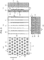
- FIG. 3 shows the structure of a portion of the mold long side that is surrounded by a square ( ⁇ ) in Fig. 2 .
- (a) is a plan view showing the front surface of the mold plate
- (b) is a plan view showing the back surface of the mold plate.
- (c) is a vertical cross-sectional view of the portion of the mold long side
- (d) is a horizontal cross-sectional view of the portion of the mold long side.
- a backup plate 23 is attached to the back side of the mold plate 21 so as to cover the cooling water channels 31 formed in the mold plate 21.
- the cooling water channels 31 are formed on the back surface of the mold plate 21.
- the cooling water channels 31 are formed from a plurality of vertically elongated grooves extending in the strand withdrawal direction A, and the plurality of grooves are arranged in the mold width direction B. Since the grooves have the vertically elongated shape, the linear flow rate in the cooling water channels 31 can be easily increased even when the amount of water supplied to the cooling water channels 31 is small. Moreover, the temperature of the water stream can be easily maintained low, and the mold plate 21 can be cooled efficiently.
- a plurality of protrusions 32 are disposed in each of the cooling water channels 31 so as to be arranged in the direction of the flow of the water stream (the direction opposite to the strand withdrawal direction A).
- the protrusions 32 can be disposed by fitting them into grooves (not shown) formed in the cooling water channels 31, joining them to the mold plate 21 by welding, or bonding them to the mold plate 21 using an adhesive.
- the water stream flowing through the cooling water channels 31 collides with the protrusions 32 and is disturbed.
- the degree of turbulence of the water stream in the regions in which the protrusions 32 are disposed increases, and the thickness of the boundary layer of the water stream (turbulence) in contact with the cooling water channels 31 decreases. Therefore, the heat transfer coefficient from the cooling water channels 31 to the water stream increases, so that the mold plate 21 in the region in which the dissimilar material-filled portions 22 are formed can be effectively cooled.
- the protrusions 32 increase the surface area of the cooling water in contact with the mold plate 21, the mold plate 21 in the region in which the dissimilar material-filled portions 22 are formed can be cooled more effectively.
- the protrusions 32 have a length in the mold width direction B equal to or more than 1/3 of the width of the cooling water channels 31 (the width in the mold width direction) and equal to or less than this width in the mold width direction.
- the height (length) of the protrusions 32 in the thickness direction of the cooling water channels 31 is equal to or more than 1 mm from the back surface of the mold plate 21 (the bottoms of the cooling water channels 31) and equal to or less than 1/2 of the thickness w of the cooling water channels 31.
- the protrusions 32 are formed on the back surface of the mold plate 21 at positions corresponding to the region in which the dissimilar material-filled portions 22 are formed.
- the protrusions 32 may be provided in the cooling water channels 31 in portions extending from the upper end of the mold plate 21 to the lower end. In the example shown in Fig. 3 , the protrusions 32 are formed so as to cover the entire cooling water channels 31 in the mold width direction.
- the degree of turbulence of the water stream flowing through the cooling water channels 31 or whether the water stream is a laminar flow can be determined using the well-known Reynolds number Re as an indicator.
- the Reynolds number Re can be computed using the density (kg/m 3 ) of the water stream, the linear velocity (m/s) of the water stream, a characteristic length (m) such as the distance through which the water stream flows, and the viscosity coefficient (Pa ⁇ s) of the water stream.
- the Reynolds number Re may be computed using the thickness w of the cooling water channels 31 with no protrusions 32 (see Fig.
- the thickness of the cooling water channels 31 in the regions in which the protrusions 32 are formed is small due to the presence of the protrusions 32, and the water stream impinging on the protrusions 32 can be considered to form turbulence.
- the dissimilar material-filled portions 22 are formed on the mold plates 21 so as to satisfy the condition of formula (4) below.
- formula (4) t: the filling depth (mm) of the dissimilar material in each dissimilar material-filled portion, and d: the width (mm) of each dissimilar material-filled portion in the mold width direction.
- the width d of the dissimilar material-filled portions 22 is preferably 2 to 20 mm.
- an equivalent circle diameter determined from formula (6) below may be used as the width d.
- Equivalent circle diameter 4 ⁇ S / ⁇ 1 / 2
- S is the area (mm 2 ) of each dissimilar material-filled portion 22.
- the width d or the equivalent circle diameter is 2 mm or more, the circular or quasi-circular recesses can be easily filled with the dissimilar material using the plating means or the thermal spraying means.
- the width d or the equivalent circle diameter is 20 mm or less, a reduction in heat flux in the dissimilar material-filled portions 22 is prevented, i.e., a delay in solidification in the dissimilar material-filled portions 22 is prevented. Therefore, concentration of stress on the solidifying shell at these portions is prevented, and the occurrence of surface cracking in the solidifying shell can be easily prevented.
- the filling thickness t of the dissimilar material is from 0.5 mm to d mm inclusive in order to satisfy formula (4). If the filling thickness t of the dissimilar material-filled portions 22 (see Fig. 3(d) ) is less than 0.5 mm, the amount of variation in heat flux in the dissimilar material-filled portions 22 may be insufficient. If the filling thickness t is excessively large, it is difficult to fill the recesses with the dissimilar material. Therefore, the filling thickness t is preferably equal to or less than the width d (mm) of the dissimilar material-filled portions in the mold width direction. Preferably, the filling thickness t is at most 10 mm. This is because, if the filling thickness t exceeds 10 mm, it is difficult to fill the recesses with the dissimilar material.
- a plating layer 51 may be formed on the front surface of each mold plate 21 so as to cover the dissimilar material-filled portions 22. In this manner, wear by the solidifying shell and surface cracking in the mold due to thermal history can be prevented.
- the plating layer 51 can be formed by plating treatment or thermal spraying treatment using commonly used nickel or an alloy containing nickel such as a nickel-cobalt alloy (Ni-Co alloy) or a nickel-chromium alloy (Ni-Cr alloy).
- Continuous steel casting for casting a slab may be performed using the mold for continuous casting described above.
- the cooling water is supplied to the mold for continuous casting such that the water stream forms turbulence in the positions in the cooling water channels in which the water stream disturbing portions are formed.
- the molten steel is medium carbon steel, surface cracking in the strand can be effectively prevented, and the continuous casting operation can be performed for a long time using the same mold.
- the mold powder used had a basicity ((% by mass CaO)/(% by mass SiO 2 )) of 1.1, a melting temperature of 1210°C, and a viscosity at 1300°C or 0.15 Pa ⁇ s.
- thermocouples were embedded in a plurality of dissimilar material-filled portions 22 in the vicinity of the meniscus M and midpoints between adjacent dissimilar material-filled portions 22, and the temperatures at these points were measured by the thermocouples. The temperatures were measured at one second intervals, and the temperature data was recorded. The distance between the molten steel-side surface of each mold plate 21 and the points at which the temperatures were measured using the thermocouples was 15 mm. The surface temperatures of the mold plates 21 were computed based on a heat transfer model using the measured temperature data.
- the protrusions 32 were disposed on the mold plate 21 side of the cooling water channels 31 as shown in Fig. 3 . However, in Inventive Example 19, the protrusions 32 were disposed on the backup plate 23 side of the cooling water channels 31.
- the average surface temperature of the mold plate 21 was computed based on a heat transfer model using the temperature data measured at the plurality of dissimilar material-filled portions 22 and the plurality of midpoints. Then the average temperatures in the 5 charges of continuous casting were averaged by the number of data samples obtained during a steady operation period, and the computed value was placed in Table 1 as "meniscus position temperature.” Moreover, the maximum value of the absolute values of the differences between the "meniscus position temperature" and the surface temperatures of the mold plate 21 computed similarly from the temperature data measured at the plurality of dissimilar material-filled portions 22 and the plurality of midpoints during the steady operation period in the 5 charges of continuous casting was placed in Table 1 as "maximum temperature variation.”
- Inventive Example 19 the continuous steel casting was performed under the same conditions as those in Inventive Example 5 except that the protrusions 32 were disposed on the backup plate 23 side.
- the rates of occurrence of surface cracking in the slabs were zero.
- the meniscus position temperature was slightly higher than that in Inventive Example 5. This may be because, since the protrusions 32 are disposed on the backup plate 23 side, the surface area of each mold plate 21 facing the cooling water channels 31 is smaller than that in Inventive Example 5.
- the maximum temperature variation was smaller than that in Inventive Example 3.
- the meniscus position temperature was higher than that in Inventive Example 3.
- the high meniscus position temperature means that the temperature at any position in the mold width direction is high, and this may be the reason that the maximum temperature variation (the difference between the average temperature and the highest temperature or the lowest temperature) is small.
- formula (3) is not satisfied. Therefore, the meniscus position temperature was higher than 300°C, and the maximum temperature variation was higher than 40°C.
- the present invention can prevent the occurrence of surface cracking in a medium carbon steel slab and effectively reduce the temperature of the mold plates in the vicinity of the meniscus in which the dissimilar material-filled portions are formed. With the present invention, the service life of the mold having the dissimilar material-filled portions formed therein can be extended.
Landscapes
- Engineering & Computer Science (AREA)
- Mechanical Engineering (AREA)
- Continuous Casting (AREA)
Abstract
Description
- The present invention relates to a mold for continuous casting that can prevent surface cracking in a strand caused by uneven cooling of a solidifying shell and can be used more times than conventional molds. The invention also relates to a continuous steel casting method using the mold for continuous casting.
- In continuous steel casting, molten steel poured into a mold is cooled using a water-cooled mold, and the surface of the molten steel in contact with the mold solidifies to thereby form a solidified layer (referred to as a "solidifying shell"). A strand including the solidifying shell as its outer shell and unsolidified molten steel inside the solidifying shell is continuously withdrawn downward from the mold while the strand is supported by strand support rolls disposed below the mold and cooled with water sprays or air-water sprays, and the central portion of the strand is thereby solidified to produce a steel slab.
- When the solidifying shell is cooled unevenly in the mold, the thickness of the solidifying shell may be nonuniform in the strand withdrawal direction and the width direction of the mold. Stress due to shrinkage or deformation of the solidifying shell itself acts on the solidifying shell. This stress concentrates on a thin-walled portion of the solidifying shell, and the stress concentration causes cracks to occur on the surface of the solidifying shell in the early stage of solidification. These surface cracks grow due to subsequent thermal stress and external forces such as bending stress and levelling stress in the continuous casting machine, and larger surface cracks are thereby formed. The cracks on the surface of the strand become surface defects of a steel product in the subsequent hot-rolling step. Therefore, to prevent the occurrence of the defects on the surface of the steel product, it is necessary to hot-scarf or grind the surface of the slab to remove the surface cracks in the slab.
- Uneven solidification in the mold tends to occur particularly in steel having a carbon content of 0.08 to 0.17% by mass (referred to as "medium carbon steel"). In the medium carbon steel, a peritectic reaction occurs during solidification. It has been considered that the uneven solidification in the mold is due to transformation stress caused by volumetric contraction during transformation from δ iron (ferrite) to y iron (austenite) by the peritectic reaction. Specifically, the solidifying shell is deformed by the strain caused by the transformation stress during the peritectic reaction, and the deformation causes the solidifying shell to be separated from the inner wall of the mold. The portion separated from the inner wall of the mold is not sufficiently cooled by the mold, so that the portion of the solidifying shell that has been separated from the inner wall of the mold has a smaller thickness. It has been considered that, when the thickness of the solidifying shell is small, the above stress concentrates on this portion to cause surface cracking.
- A number of proposals have been made for the purpose of preventing surface cracking in a steel strand undergoing the peritectic reaction. For example,
Patent Literature 1 proposes a mold for continuous casting that has a plurality of dissimilar material-filled portions formed independently on inner wall surfaces of the mold and having a thermal conductivity different from that of a copper alloy forming mold plates (referred to also as "copper mold plates"). It is stated inPatent Literature 1 that the use of the mold can effectively prevent surface cracking in the strand due to uneven cooling of the solidifying shell in the early stage of solidification. In particular, it is stated that surface cracking in the strand due to unevenness in the thickness of the solidifying shell caused by transformation from δ iron to y iron in medium carbon steel undergoing the peritectic reaction can be effectively prevented. - PTL 1:
Japanese Unexamined Patent Application Publication No. 2017-39165 - In the mold for continuous steel casting described in
Patent Literature 1, the dissimilar material-filled portions formed of a material different from the material of the mold plates are formed in the mold plates. Therefore, the thermal expansion coefficient of the mold plates differs from the thermal expansion coefficient of the dissimilar material-filled portions, and thermal stress is likely to concentrate on boundary portions therebetween, so that cracks are likely to occur on the surface of the mold. It is stated inPatent Literature 1 that it is preferable to provide a plating layer covering the dissimilar material-filled portions on the inner wall surfaces of the mold for the purpose of preventing cracks on the surface of the mold caused by thermal history and that this can extend the service life of the mold. However, even when the plating layer is provided on the inner wall surfaces of the mold, a difference in thermal stress is still present between the mold plates and the dissimilar material-filled portions, and therefore the service life of the mold having the dissimilar material-filled portions formed therein tends to be short. There is therefore a need for a technique for extending the service life of the mold described inPatent Literature 1. - The present invention has been made in view of the above circumstances, and it is an object to provide a mold for continuous casting that has dissimilar material-filled portions formed therein and can be used significantly more times than conventional molds. It is another object to provide a continuous steel casting method that uses the mold for continuous casting.
- The present inventors have conducted extensive studies to solve the foregoing problem. The inventors have found that it is effective to increase the heat transfer coefficient between cooling water channels corresponding to regions in which dissimilar material-filled portions are formed and a water stream passing through the cooling water channels to thereby remove heat from a mold plate in the above region effectively. This is because of the following reason. By effectively removing heat from the mold plate in the region in which the dissimilar material-filled portions are formed, the temperature of the dissimilar material-filled portions and the temperature of the mold plate decrease, and thermal stress in the boundary portions between the mold plate and the dissimilar material-filled portions is thereby reduced.
- The present invention is based on the above findings, and the summary of the invention is as follows.
- [1] A mold for continuous steel casting including:
- a mold plate made of a copper alloy and having a front surface forming an inner wall surface of the mold and a back surface on which a cooling water channel is formed; and
- a backup plate attached to the mold plate so as to cover the cooling water channel,
- wherein a dissimilar material-filled portion filled with a dissimilar material having a thermal conductivity different from the thermal conductivity of the mold plate is formed in a recessed portion that is formed on the front surface of the mold plate and located in a region including at least a meniscus, and
- wherein a water stream disturbing portion is formed in the cooling water channel on the back surface of the mold plate, the water stream disturbing portion disturbing a water stream and increasing the surface area of the cooling water channel, the water stream disturbing portion being formed in a region corresponding to the region in which the dissimilar material-filled portion is formed.
- [2] The mold for continuous steel casting according to [1], wherein the water stream disturbing portion includes a plurality of protrusions that are arranged in a flow direction of the water stream and extend in a mold width direction of the cooling water channel and a thickness direction of the cooling water channel.
- [3] The mold for continuous steel casting according to [1], wherein the water stream disturbing portion includes a plurality of protrusions arranged in the cooling water channel in a staggered manner.
- [4] The mold for continuous steel casting according to any of [1] to [3], wherein a plurality of the dissimilar material-filled portions are formed and include a plurality of circular recesses or quasi-circular recesses, and
wherein the plurality of dissimilar material-filled portions are formed such that, in an area extending from an upper end of the region in which the plurality of dissimilar material-filled portions are formed to an lower end thereof on the front surface of the mold plate, a heat flux from the inner wall surface of the mold toward the cooling water channel varies periodically on the inner wall surface of the mold. - [5] The mold for continuous steel casting according to [4], wherein the dissimilar material-filled portions and the cooling water channel are formed so as to satisfy at least one of the conditions of the following formulas (1) to (3):


- d: a width (mm) of each dissimilar material-filled portion in a mold width direction,
- P: a separation distance (mm), in the mold width direction, between adjacent dissimilar material-filled portions of the plurality of dissimilar material-filled portions,
- S: a separation distance (mm), in the mold width direction, between adjacent cooling water channels of a plurality of the cooling water channels formed on the back surface of the mold plate,
- e: a width (mm) of each dissimilar material-filled portion in a strand withdrawal direction,
- L: a separation distance (mm), in the strand withdrawal direction, between adjacent dissimilar material-filled portions of the plurality of dissimilar material-filled portions,
- Vc: a strand withdrawal speed (m/min) in a continuous steel casting process,
- f: an oscillation frequency (1/min) of the mold for continuous casting in the continuous steel casting process, and
- F: a separation distance (mm), in the strand withdrawal direction, between adjacent protrusions of a plurality of protrusions disposed in each cooling water channel.
- [6] The mold for continuous steel casting according to [4] or [5], wherein the dissimilar material-filled portions are formed so as to satisfy the condition of formula (4) below:

- t: a filling depth (mm) of the dissimilar material in each dissimilar material-filled portion, and
- d: a width (mm) of each dissimilar material-filled portion in a mold width direction.
- [7] The mold for continuous steel casting according to any of [1] to [6], wherein a plating layer is formed on the front surface of the mold plate so as to cover the dissimilar material-filled portion.
- [8] A continuous steel casting method that uses the mold for continuous steel casting according to any of [1] to [7], the method including supplying cooling water to the mold for continuous casting such that the water stream is turbulent in a position in which the water stream disturbing portion is formed in the cooling water channel. Advantageous Effects of Invention
- In the mold for continuous steel casting according to the present invention, the water stream disturbing portion that disturbs the water stream and increases the surface area of the cooling water channel is formed in a portion of the cooling water channel that corresponds to the region in which the dissimilar material-filled portion is formed. Therefore, in this portion of the cooling water channel, the heat transfer coefficient between the water stream and the cooling water channel is large, and the amount of convective heat transfer is increased, so that heat in the mold plate in the region in which the dissimilar material-filled portion is formed can be effectively removed. By effectively cooling the dissimilar material-filled portion and the mold plate, the thermal stress generated in the boundary portion between the mold plate and the dissimilar material-filled portion can be effectively reduced. Therefore, the occurrence of surface cracking in a strand of the steel type undergoing the peritectic reaction is prevented, and the number of times the mold having the dissimilar material-filled portion formed therein can be used can be increased, i.e., the service life of the mold can be extended.
-
- [
Fig. 1] Fig. 1 is a perspective view of a mold for continuous steel casting. - [
Fig. 2] Fig. 2 is an illustration showing an example of the front surface of a mold plate formed in a long side of the mold in an embodiment of the present invention. - [
Fig. 3] Fig. 3 shows illustrations of the structure of a portion of the long side of the mold that is surrounded by a square (□) inFig. 2 . - [
Fig. 4] Fig. 4 is an illustration showing the back surface of a mold plate in another embodiment of the present invention. - [
Fig. 5] Fig. 5 is a vertical cross-sectional view of a long side of a mold in another embodiment of the present invention. - The present invention will next be described specifically with reference to the accompanying drawings.
- Before the present invention is described, a continuous steel casting method will be briefly described. A perspective view of a mold for continuous casting is shown in
Fig. 1 . Themold 1 for continuous casting (hereinafter referred to simply as a "mold 1") that is used to produce a slab by continuous casting includes a pair of moldlong sides 2 facing each other and a pair of moldshort sides 3 facing each other and sandwiched between the mold long sides 2. A tundish (not shown) that containsmolten steel 4 is disposed above themold 1, and a submergednozzle 5 is disposed on the bottom of the tundish. The pair of moldlong sides 2 and the pair of moldshort sides 3 form a rectangular inner space in themold 1, and the submergednozzle 5 is inserted into the inner space. As described later, the side of each of the moldlong sides 2 and the moldshort sides 3 that is to be in contact with themolten steel 4 is formed of a copper alloy-made mold plate, and a backup plate is disposed on the back side of the mold plate. - Cooling water channels are formed in each of the copper alloy-made mold plates formed in the mold
long sides 2 and the moldshort sides 3 and disposed on a surface of the mold plate opposite to its surface to be in contact with themolten steel 4, and cooling water is caused to pass through the cooling water channels to cool themold 1. During the continuous steel casting operation, themolten steel 4 is poured into the inner space of themold 1 through the submergednozzle 5 and cooled and solidified in themold 1 to form a solidifying shell on the contact surface of themold 1. A strand including the solidifying shell as its outer shell and the unsolidifiedmolten steel 4 inside the solidifying shell is continuously withdrawn from themold 1 in a strand withdrawal direction A, i.e., a vertically downward direction, to thereby produce a steel slab. In themold 1, the mold plates are in contact with themolten steel 4 and the high-temperature strand. Therefore, the surface temperature of the mold plates (the temperature on the side in contact with the molten steel) increases and is highest near the position of a meniscus M (the top surface of the molten steel in the mold) in the mold. InFig. 1 , the position of the meniscus M is indicated by a dash-dot line. - It is preferable that heat is removed from the solidifying shell uniformly in the strand withdrawal direction A and a mold width direction B particularly at the position of the meniscus M on the inner wall surface of the mold, but this depends on the type of steel. This is because uniform growth of the thickness of the solidifying shell is facilitated. The strand withdrawal direction A is orthogonal to the mold width direction B. A copper alloy having high deformation resistance to thermal stress and high thermal conductivity allowing the cooling effect of the cooling water to increase is used for the mold plates.
- A plurality of strand support rolls (not shown) are disposed below the
mold 1, and water spray nozzles or air mist spray nozzles are disposed between adjacent strand support rolls. While the cooling water is sprayed onto the surface of the strand through the water spray nozzles or the air mist spray nozzles to cool the strand, the strand supported by the strand support rolls is withdrawn. After completion of solidification also at the center of the strand, the resulting strand is cut into a prescribed length. - A steel slab having the prescribed length and to be subjected to hot rolling in the next step is produced in the manner described above.
- In the present invention, dissimilar material-filled portions are provided in the mold plates cooled by the cooling water channels, and members that disturb a water stream and increase the surface area of the cooling water channels are disposed in the cooling water channels. The heat transfer coefficient between the cooling water and the cooling water channels is thereby increased, and the heat of the mold plates is effectively removed. In this manner, the temperature of the dissimilar material-filled portions and the temperature of the mold plates therearound are reduced, and thermal stress generated in the boundary portions between the mold plates and the dissimilar material-filled portions is reduced to thereby extend the service life of the mold for continuous casting.
- An example of an embodiment of the mold for continuous casting according to the present invention will be described. Each of the mold
long sides 2 and the moldshort sides 3 formed in themold 1 for continuous casting includes: a mold plate having a front surface forming a mold inner wall surface and a back surface on which cooling water channels are formed; and a backup plate attached to the mold plate using bolts and nuts. - An example of the front surface of the mold plate formed in each of the mold
long sides 2 is shown inFig. 2 . Dissimilar material-filledportions 22 filled with a dissimilar material having a thermal conductivity different from the thermal conductivity of themold plate 21 are formed in recesses (dents) formed on the front surface of themold plate 21 and located in a region including the meniscus M. The dissimilar material-filledportions 22 are formed in a region near the meniscus that includes at least the meniscus M and arranged in the strand withdrawal direction A and the mold width direction B. The dissimilar material may be formed into a shape fittable to the recesses and fitted into the recesses to fill the recesses with the dissimilar material. Alternatively, the recesses may be filled with the dissimilar material using plating means or thermal spraying means. When the recesses are filled with the dissimilar material using the plating means or the thermal spraying means, the occurrence of gaps between the recesses and the dissimilar material can be prevented. - A plurality of circular recesses are formed on the front surface of the
mold plate 21, and the circular recesses are filled with the dissimilar material to form a plurality of independent dissimilar material-chargedportions 22. In this case, it is preferable that the dissimilar material-chargedportions 22 are arranged regularly such that the heat flux from the mold inner wall surface to the cooling water channels varies periodically on the mold inner wall surface. - By arranging the plurality of dissimilar material-filled
portions 22 in the region including the vicinity of the meniscus M, the thermal resistance of themold plate 21 in the strand withdrawal direction A in the region including the vicinity of the meniscus M and the mold width direction B increases and decreases regularly and periodically. In this manner, the heat flux in the vicinity of the meniscus M, i.e., the heat flux from the solidifying shell to themold plate 21 in the early stage of solidification, increases and decreases regularly and periodically. The regular and periodic increase and decrease of the heat flux reduces stress generated by transformation from δ iron to y iron and thermal stress, so that the deformation of the solidifying shell caused by these stresses decreases. Since the deformation of the solidifying shell is small, a non-uniform heat flux distribution caused by the deformation of the solidifying shell is uniformized, and the stress generated is dispersed, so that the amount of the corresponding strain decreases. Therefore, the occurrence of surface cracking on the surface of the solidifying shell is prevented. - The shape of the recesses on the front surface of the
mold plate 21 may not be perfect circular (referred to as "circular recesses") and may be quasi-circular (referred to as "quasi-circular recesses"). The quasi-circular shape is a shape with no sharp corners such as an elliptical shape or a square or rectangular shape with circular or elliptical corners. Moreover, a petal-like shape may be used. - To allow the change in the heat flux on the mold inner wall surface to be periodic in a reliable manner, it is preferable that the distances between adjacent dissimilar material-filled
portions 22 are the same. The thermal conductivity of the dissimilar material is preferably 80% or less or 125% or more of the thermal conductivity of the mold plates formed in the moldlong sides 2 and the mold short sides 3. The thermal conductivity of the dissimilar material varies depending on a change in the temperature of the environment. Therefore, the thermal conductivity of the dissimilar material and the thermal conductivity of the mold plate are based on those at room temperature (normal temperature) during production of the mold. When the thermal conductivity of the dissimilar material at room temperature differs by about 20% from the thermal conductivity of the mold plates, the regular and periodic increase and decrease of the heat flux on the mold inner wall surface can reduce stress generated by transformation from δ iron to y iron and thermal stress. It is only necessary that the stress generated by the transformation described above etc. can be reduced to prevent surface cracking in the strand. Therefore, it is not always necessary that the thermal conductivity of the dissimilar material be in the above range, and it is not always necessary that the distances between the dissimilar material-filledportions 22 be the same. - Examples of the dissimilar material whose thermal conductivity is 80% or less of the thermal conductivity of the mold plates include Ni (thermal conductivity: about 90 W/(m×K)) and Ni alloys (thermal conductivity: about 40 to 90 W/(m×K)) that are easily plated and thermally sprayed. A copper alloy (thermal conductivity: about 100 to 385 W/(m×K)) may be used for the mold plates, and, for example, a high-thermal conductivity copper alloy (thermal conductivity: about 318 W/(m×K)) or a low-thermal conductivity copper alloy (thermal conductivity: about 119 to 239 W/(m×K)) for electromagnetic stirring may be used. However, metals other than the Ni alloys and the copper alloys can be used for the dissimilar material and the mold plates.
- Pure copper (thermal conductivity: about 398 W/(m×K)) and the copper alloys described above may be used for the mold plates. In particular, when the molten steel in the mold is electromagnetically stirred, it is preferable to use a copper alloy containing several percent by mass of components other than the copper component and having reduced electric conductivity in order to prevent attenuation of the intensity of a magnetic field from a coil to the molten steel. The thermal conductivity of the copper alloy is lower than pure copper. Specifically, it is preferable that the dissimilar material and/or the material of the mold plates is appropriately selected according to the application of the
mold 1 to control the thermal conductivity of the dissimilar material and the thermal conductivity of the mold plates. - Dissimilar material-filled portions may be formed on the front surface of each of the unillustrated mold
short sides 3 whose description is omitted, as in the mold long sides 2. However, in a slab strand, stress is likely to concentrate on the long sides of the solidifying shell because of its shape, and surface cracking is likely to occur on the long sides. Therefore, although it is necessary that the dissimilar material-filled portions be provided on the mold long sides of the continuous casting mold for a slab strand, it is not always necessary that the dissimilar material-filled portions be provided on the mold short sides. - In consideration of the influence on initial solidification, it is preferable that the dissimilar material-filled
portions 22 are provided on the mold inner wall surface in a region extending from a position spaced a distance Q upward from the position of the meniscus M during steady casting to a position spaced a distance R downward from the meniscus. The distance Q is any value larger than zero. The distance R can be computed using formula (5) below.

- The distance R relates to the time required for the solidifying shell (strand) after the start of solidification to pass through the region in which the dissimilar material-filled
portions 22 are formed. Preferably, the solidifying shell (strand) stays in the region in which the dissimilar material-filledportions 22 are disposed for at least 2 seconds after the start of solidification. To allow the solidifying shell (strand) to be present in the region in which the dissimilar material-filledportions 22 are disposed for at least 2 seconds after the start of solidification, it is necessary that the dissimilar material-filledportions 22 be disposed in a region extending at least the distance R determined from formula (5) downward from the meniscus M. - When the amount of time the solidifying shell after the start of solidification stays in the region in which the dissimilar material-filled
portions 22 are disposed is at least 2 seconds, the effect of the periodic change in the heat flux from the mold inner wall surface to the cooling water channels by the dissimilar material-filledportions 22 can be sufficiently obtained. Specifically, when the amount of time the solidifying shell stays in the region in which the dissimilar material-filledportions 22 are disposed is at least 2 seconds, the effect of preventing surface cracking in the strand can be obtained even during highspeed casting or casting of medium carbon steel during which surface cracking is likely to occur. However, to stably obtain the effect of the periodic change in the heat flux by the dissimilar material-filledportions 22, it is more preferable that the time required for the solidifying shell to pass through the region in which the dissimilar material-filledportions 22 are disposed is at least 4 seconds. In a continuous thin-slab casting machine, since the strand withdrawal speed is high, the distance R is large, and the range in the strand withdrawal direction A in which the dissimilar material-filledportions 22 are disposed is large, so that the processing cost of the mold may be high. Even in this case, when the amount of time required for the solidifying shell to pass through the dissimilar material-filledportions 22 is at least 1 second, the effect of the periodic change in the heat flux corresponding to the amount of time can be obtained. - No particular limitation is imposed on the upper end of the region in which the dissimilar material-filled
portions 22 are formed so long as the upper end is located above the meniscus M. Therefore, the distance Q is any value larger than zero. However, since the meniscus M fluctuates vertically during casting, it is preferable that the dissimilar material-filledportions 22 are formed up to a position about 10 mm above the meniscus M such that the upper end of the region of the dissimilar material-filledportions 22 is always located above the meniscus M. Preferably, the upper end of this region is located up to about 20 mm above the meniscus M. The position of the meniscus M is generally 60 to 150 mm below the upper ends of the moldlong sides 2, and the region in which the dissimilar material-filledportions 22 are formed is determined accordingly. - In the continuous steel casting process, since the high-temperature molten steel is poured into the inner space of the mold, the temperature of the mold plates increases. Therefore, the cooling water channels are formed in the mold plates formed in the mold long sides and the mold short sides, and cooling water is caused to pass through the cooling water channels to cool the mold plates. The form of the mold is thereby maintained. However, since the thermal expansion coefficient of the dissimilar material-filled
portions 22 differs from the thermal expansion coefficient of themold plates 21, thermal stress concentrated on the boundaries therebetween may cause cracks to occur on the front surface of each mold plate (the mold inner wall surface). - Accordingly, in the present invention, water stream disturbing portions that disturb a water stream and increase the surface area of the cooling water channels are formed in portions of the cooling water channels that cool the regions of the
mold plates 21 in which the dissimilar material-filledportions 22 are formed to thereby increase the heat transfer coefficient between the cooling water channels and the water stream in the above regions. In this manner, heat removal from the mold plates in the regions in which the dissimilar material-filledportions 22 are formed is facilitated. - The water stream disturbing portions will be described.
Fig. 3 shows the structure of a portion of the mold long side that is surrounded by a square (□) inFig. 2 . InFig. 3 , (a) is a plan view showing the front surface of the mold plate, and (b) is a plan view showing the back surface of the mold plate. (c) is a vertical cross-sectional view of the portion of the mold long side, and (d) is a horizontal cross-sectional view of the portion of the mold long side. As shown inFigs. 3(c) and 3(d) , abackup plate 23 is attached to the back side of themold plate 21 so as to cover thecooling water channels 31 formed in themold plate 21. - As shown in
Fig. 3(b) , the coolingwater channels 31 are formed on the back surface of themold plate 21. The coolingwater channels 31 are formed from a plurality of vertically elongated grooves extending in the strand withdrawal direction A, and the plurality of grooves are arranged in the mold width direction B. Since the grooves have the vertically elongated shape, the linear flow rate in thecooling water channels 31 can be easily increased even when the amount of water supplied to thecooling water channels 31 is small. Moreover, the temperature of the water stream can be easily maintained low, and themold plate 21 can be cooled efficiently. - In the
mold 1 for continuous casting according to the present invention, the water stream disturbing portions that disturb the water stream are formed in thecooling water channels 31 on the back surface of themold plate 21 so as to correspond to the region in which the dissimilar material-filledportions 22 are formed. For example, as shown inFigs. 3(b) to 3(d) , the water stream disturbing portions may be formed fromprotrusions 32 disposed so as to extend in the mold width direction B of the coolingwater channels 31 and the thickness direction of the coolingwater channels 31. Specifically, theprotrusions 32 are disposed so as to spread in the mold width direction B of the coolingwater channels 31 and the thickness direction of the coolingwater channels 31 such that the channel areas of the coolingwater channels 31 are reduced to form obstacles to the water stream flowing through the coolingwater channels 31. - To further disturb the water stream in the cooling water channels and further increase the surface area of the cooling
water channels 31, it is preferable that a plurality ofprotrusions 32 are disposed in each of the coolingwater channels 31 so as to be arranged in the direction of the flow of the water stream (the direction opposite to the strand withdrawal direction A). Theprotrusions 32 can be disposed by fitting them into grooves (not shown) formed in thecooling water channels 31, joining them to themold plate 21 by welding, or bonding them to themold plate 21 using an adhesive. - The water stream flowing through the cooling
water channels 31 collides with theprotrusions 32 and is disturbed. In this case, the degree of turbulence of the water stream in the regions in which theprotrusions 32 are disposed increases, and the thickness of the boundary layer of the water stream (turbulence) in contact with the coolingwater channels 31 decreases. Therefore, the heat transfer coefficient from the coolingwater channels 31 to the water stream increases, so that themold plate 21 in the region in which the dissimilar material-filledportions 22 are formed can be effectively cooled. Moreover, since theprotrusions 32 increase the surface area of the cooling water in contact with themold plate 21, themold plate 21 in the region in which the dissimilar material-filledportions 22 are formed can be cooled more effectively. - Preferably, the
protrusions 32 have a length in the mold width direction B equal to or more than 1/3 of the width of the cooling water channels 31 (the width in the mold width direction) and equal to or less than this width in the mold width direction. Preferably, the height (length) of theprotrusions 32 in the thickness direction of the coolingwater channels 31 is equal to or more than 1 mm from the back surface of the mold plate 21 (the bottoms of the cooling water channels 31) and equal to or less than 1/2 of the thickness w of the coolingwater channels 31. InFig. 3 , theprotrusions 32 are formed on the back surface of themold plate 21 at positions corresponding to the region in which the dissimilar material-filledportions 22 are formed. However, theprotrusions 32 may be provided in thecooling water channels 31 in portions extending from the upper end of themold plate 21 to the lower end. In the example shown inFig. 3 , theprotrusions 32 are formed so as to cover the entirecooling water channels 31 in the mold width direction. - The degree of turbulence of the water stream flowing through the cooling
water channels 31 or whether the water stream is a laminar flow can be determined using the well-known Reynolds number Re as an indicator. Generally, the Reynolds number Re can be computed using the density (kg/m3) of the water stream, the linear velocity (m/s) of the water stream, a characteristic length (m) such as the distance through which the water stream flows, and the viscosity coefficient (Pa×s) of the water stream. In the mold for continuous casting according to the present invention, the Reynolds number Re may be computed using the thickness w of the coolingwater channels 31 with no protrusions 32 (seeFig. 3(c) ) as "the characteristic length (m)." When the cooling water is supplied to thecooling water channels 31 under the conditions that the Reynolds number Re computed on the assumption that noprotrusions 32 are provided exceeds 2300, the thickness of the coolingwater channels 31 in the regions in which theprotrusions 32 are formed is small due to the presence of theprotrusions 32, and the water stream impinging on theprotrusions 32 can be considered to form turbulence. - In the mold for continuous casting according to the present invention, it is preferable that the dissimilar material-filled
portions 22 and thecooling water channels 31 are formed in eachmold plate 21 such that at least one of the conditions of the following formulas (1) to (3) is satisfied.


- d: the width (mm) of each dissimilar material-filled portion in the mold width direction.
- P: the separation distance (mm), in the mold width direction, between adjacent dissimilar material-filled portions of the plurality of dissimilar material-filled portions.
- S: the separation distance (mm), in the mold width direction, between adjacent cooling water channels of the plurality of cooling water channels formed on the back surface of the mold plate.
- e: the width (mm) of each dissimilar material-filled portion in the strand withdrawal direction.
- L: the separation distance (mm), in the strand withdrawal direction, between adjacent dissimilar material-filled portions of the plurality of dissimilar material-filled portions.
- Vc: the strand withdrawal speed (m/min) in the continuous steel casting process.
- f: the oscillation frequency (1/min) of the mold for continuous casting in the continuous steel casting process.
- F: the separation distance (mm), in the strand withdrawal direction, between adjacent protrusions of the plurality of protrusions disposed in each cooling water channel.
- The "separation distance" between two adjacent portions is their center-to-center distance in the strand withdrawal direction A or the mold width direction B (see
Fig. 3 ). - In the mold for continuous casting according to the present invention, it is preferable that the dissimilar material-filled
portions 22 are formed on themold plates 21 so as to satisfy the condition of formula (4) below.

- In the mold for continuous casting, the cooling
water channels 31 are formed on the back surface of eachmold plate 21. Therefore, portions of themold plate 21 that are close to thecooling water channels 31 are cooled to a greater extent than portions far from the coolingwater channels 31, so that the degree of cooling of the front surface of themold plate 21 tends to be non-uniform. To reduce the influence of cooling by the coolingwater channels 31 on the periodic increase and decrease in the thermal resistance by the dissimilar material-filledportions 22, it is preferable that formula (1) is satisfied. Specifically, it is preferable that the separation distance P of the dissimilar material-filledportions 22 in the mold width direction B is equal to or more than the width d of the dissimilar material-filledportions 22 and equal to or less than the separation distance S of the cooling water channels 31 (seeFig. 3(d) ). - Since each
mold plate 21 is cooled by the cooling water flowing through the coolingwater channels 31 on the back surface of themold plate 21, heat is removed from themold plate 21 radially through the coolingwater channels 31. Therefore, on the front surface of themold plate 21, portions close to thecooling water channels 31 are cooled differently from portions far from the coolingwater channels 31. To more effectively obtain the effect of reducing the stress generated by transformation from δ iron to y iron and the thermal stress by the periodic increase and decrease in the thermal resistance by the dissimilar material-filledportions 22, it is preferable that the heat flux varies with a period smaller than the separation distance S of the coolingwater channels 31. Therefore, it is preferable that formula (1) is satisfied, i.e., the separation distance P of the dissimilar material-filledportions 22 in the mold width direction B is equal to or less than the separation distance S of the coolingwater channels 31, and it is preferable that the width d of the dissimilar material-filledportions 22 is less than the separation distance P. - The width d of the dissimilar material-filled
portions 22 is preferably 2 to 20 mm. When the dissimilar material-filledportions 22 have a quasi-circular shape, an equivalent circle diameter determined from formula (6) below may be used as the width d.

portion 22. - When the width d or the equivalent circle diameter is 2 mm or more, the circular or quasi-circular recesses can be easily filled with the dissimilar material using the plating means or the thermal spraying means. When the width d or the equivalent circle diameter is 20 mm or less, a reduction in heat flux in the dissimilar material-filled
portions 22 is prevented, i.e., a delay in solidification in the dissimilar material-filledportions 22 is prevented. Therefore, concentration of stress on the solidifying shell at these portions is prevented, and the occurrence of surface cracking in the solidifying shell can be easily prevented. - Generally, in the continuous steel casting method, the mold is oscillated when the molten steel is poured into the mold while a mold powder is added to the top surface of the molten steel in order to prevent sticking of the molten steel to the mold. It is known that periodic oscillation marks caused by the oscillations are formed on the surface of the strand in the strand withdrawal direction A, and the thickness of the stand tends to vary periodically in the strand withdrawal direction A.
- When the width e (mm) of the dissimilar material-filled
portions 22, the separation distance L (mm) between adjacent dissimilar material-filledportions 22, the strand withdrawal speed Vc (m/min), and the oscillation frequency f (1/min) of the mold satisfy formula (2), transverse cracks in the strand can be prevented. Specifically, when the width e of the dissimilar material-filledportions 22 in the strand withdrawal direction A is smaller than the length (spacing) of one cycle of the increase and decrease in the thickness of the strand in the strand withdrawal direction A caused by the oscillation marks, transverse cracks in the strand can be prevented. - The separation distance F between
adjacent protrusions 32 and the separation distance L between adjacent dissimilar material-filledportions 22 in the strand withdrawal direction A may satisfy formula (3). This means that theprotrusions 32 are formed at positions corresponding to portions between dissimilar material-filledportions 22 adjacent in the strand withdrawal direction A. In this case, the surface areas of the cooling water channels in these portions increase by the surface area of the protrusions, and the water stream tends to form turbulence in the cooling water channels. Therefore, heat can be removed from themold plate 21 more effectively. - Preferably, the filling thickness t of the dissimilar material is from 0.5 mm to d mm inclusive in order to satisfy formula (4). If the filling thickness t of the dissimilar material-filled portions 22 (see
Fig. 3(d) ) is less than 0.5 mm, the amount of variation in heat flux in the dissimilar material-filledportions 22 may be insufficient. If the filling thickness t is excessively large, it is difficult to fill the recesses with the dissimilar material. Therefore, the filling thickness t is preferably equal to or less than the width d (mm) of the dissimilar material-filled portions in the mold width direction. Preferably, the filling thickness t is at most 10 mm. This is because, if the filling thickness t exceeds 10 mm, it is difficult to fill the recesses with the dissimilar material. - As shown in
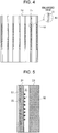
Fig. 4 , a plurality ofprotrusions 42 may be arranged in a staggered configuration in each coolingwater channel 31. In this case, as in the case ofFig. 3 , the water stream in thecooling water channels 31 in which theprotrusions 42 are disposed tends to form turbulence. When theprotrusions 42 are ellipsoids having a shape formed, for example, by cutting a rugby ball into halves, the degree of turbulence of the water stream is high, and the heat transfer coefficient between the water stream and themold plates 21 increases, so that the regions of themold plate 21 in which the dissimilar material-filledportions 22 are formed can be effectively cooled. The "staggered configuration" means that a group ofprotrusions 42 arranged in the mold width direction B are disposed in positions shifted by one half of the widthwise spacing of the group of theprotrusions 42 relative to an adjacent group ofprotrusions 42 disposed above and/or below the above group in the strand withdrawal direction A and arranged in the mold width direction B. In the present description, even when the number ofprotrusions 42 arranged in the mold width direction B is one, the term "group" is used. - In
Fig. 3 , theprotrusions 32 are disposed on themold plate 21 side of the coolingwater channels 31, i.e., on the bottom side of the coolingwater channels 31. However, theprotrusions 32 may be disposed on thebackup plate 23 sides of the coolingwater channels 31. In this case, although the surface area of eachmold plate 21 facing the cooling water is smaller, the water stream still tends to form turbulence in the cooling water channels. Therefore, heat can be removed from themold plate 21 more effectively, and the effects of the invention can be sufficiently obtained. - As shown in
Fig. 5 , aplating layer 51 may be formed on the front surface of eachmold plate 21 so as to cover the dissimilar material-filledportions 22. In this manner, wear by the solidifying shell and surface cracking in the mold due to thermal history can be prevented. Theplating layer 51 can be formed by plating treatment or thermal spraying treatment using commonly used nickel or an alloy containing nickel such as a nickel-cobalt alloy (Ni-Co alloy) or a nickel-chromium alloy (Ni-Cr alloy). - Continuous steel casting for casting a slab may be performed using the mold for continuous casting described above. Specifically, the cooling water is supplied to the mold for continuous casting such that the water stream forms turbulence in the positions in the cooling water channels in which the water stream disturbing portions are formed. In this case, particularly when the molten steel is medium carbon steel, surface cracking in the strand can be effectively prevented, and the continuous casting operation can be performed for a long time using the same mold.
- A mold for continuous casting in which the dissimilar material-filled portions described in
Fig. 2 were formed on the mold inner wall surface but theprotrusions 32 shown inFigs. 3(b) to 3(d) were not formed in the cooling water channels was prepared. This mold was used to perform a continuous steel casting operation (comparative example). In the prepared mold for continuous casting, the length of the mold long sides was 2.1 m, and the length of the mold short sides was 0.22 m. The mold had a rectangular inner space. The mold plates formed in the mold long sides and the mold short sides were produced using a copper alloy having a thermal conductivity at room temperature of about 380 (W/(m×K)). - The steel subjected to continuous casting was medium carbon steel containing chemical components including C: 0.08 to 0.17% by mass, Si: 0.10 to 0.30% by mass, Mn: 0.50 to 1.20% by mass, P: 0.010 to 0.030% by mass, S: 0.005 to 0.015% by mass, and Al: 0.020 to 0.040% by mass, with the balance being Fe and unavoidable impurities. The mass of the molten steel per charge was 300 tons. In the comparative example, while the molten medium carbon steel was poured into the prepared mold, the mold was oscillated in the strand withdrawal direction and cooled to form a solidifying shell. The solidifying shell was withdrawn to cast a slab. The strand withdrawal speed Vc was set to 2.0 (m/min).
- During the continuous casting operation, a mold powder was added to the molten steel in the oscillating mold to prevent sticking of the molten steel to the mold. The mold powder used had a basicity ((% by mass CaO)/(% by mass SiO2)) of 1.1, a melting temperature of 1210°C, and a viscosity at 1300°C or 0.15 Pa×s.
- In the continuous casting operation, it was aimed to perform 3000 charges of continuous casting without replacing the mold. After every 100 casting charges, the presence of surface cracking in the mold long sides was checked. Whether cracks were present on the front surfaces of the mold long sides was visually checked. When cracks were found, the continuous casting operation was stopped. For each continuous casting charge, the presence of the surface cracking in the slab was checked. The presence of surface cracking in the slab was checked by visually observing the surface of the slab subjected to a liquid penetrant test (color check) to examine the presence of longitudinal cracks in the strand withdrawal direction and the presence of transverse cracks in the strand width direction.
- In the mold in the comparative example, a plurality of circular recesses were formed in the mold plates formed in the mold long sides. The recesses were filled with a nickel alloy (thermal conductivity at room temperature: 80 (W/(m×K))) serving as the dissimilar material using plating means to thereby form dissimilar material-filled portions. The
plating layer 51 shown inFig. 5 was provided on the mold inner wall surface. The same nickel alloy as the dissimilar material was used as the material of theplating layer 51. - A mold for continuous casting having the dissimilar material-filled
portions 22 formed on the front surfaces of themold plates 21 as shown inFig. 2 and theprotrusions 32 formed in the cooling water channels as shown inFig. 3 was prepared. This mold was used to perform a continuous steel casting operation (Inventive Example 1). In Inventive Example 1, the filling depth t of the dissimilar material was 1 mm, and the dissimilar material-filledportions 22 and theprotrusions 32 were disposed so as to satisfy formulas (1), (2), and (3) . - In the mold in Inventive Example 1, as in the comparative example, the
plating layer 51 was provided, and the nickel alloy was used as the material of theplating layer 51, as in the comparative example. In Inventive Example 1, the continuous steel casting operation was performed under the same conditions as those in the comparative example except for the continuous casting mold used. For example, the rate of supply of the cooling water to the mold in the comparative example was such that the Reynolds number Re of the water stream in the cooling water channels in the mold with no protrusions formed was in a turbulent range. In Inventive Example 1 also, the cooling water was supplied to the mold such that the rate of supply of the cooling water was the same as that in the comparative example. - In Inventive Example 1, it was aimed to perform 3000 charges of continuous casting without replacing the mold. After every 100 casting charges, the presence of surface cracking in the mold long sides was checked, as in the comparative example. When cracks were found on the front surfaces of the mold long sides, the continuous casting operation was stopped. For each continuous casting charge, the presence of the surface cracking in the slab was checked.
- In the comparative example, surface cracking was found in the mold plates formed in the mold long sides after completion of the 2400th casting charge. However, in Inventive Example 1, no surface cracking occurred in the mold plates formed in the mold long sides even after completion of the 3000th casting charge. Specifically, in Inventive Example 1, the continuous casting could be performed the target number of times without causing surface cracking in the mold plates formed in the mold long sides.
- As for the service life of the mold, in the comparative example, surface cracking was found in the mold plates formed in the mold long sides by inspection performed after completion of the 2400th continuous casting charge. However, in Inventive Example 1, 3000 charges of continuous casting, which is the target number of charge times, could be performed without replacing the mold, and the service life of the mold could be improved as compared with the mold in the comparative example. This may be because the protrusions 32 (water stream disturbing portions) allow the water stream to form a more highly turbulent flow than that in the comparative example and increase the surface areas of the cooling water channels to cool the mold more efficiently.
- Whether surface cracking occurred in the slabs in the comparative example and Inventive Example 1 was checked. However, no surface cracking was found in both the cases. In both the molds, the occurrence of surface cracking in the slab could be prevented. This may be because the dissimilar material-filled portions can effectively prevent surface cracking due to unevenness in thickness of the solidifying shell caused by transformation from δ iron to y iron that occurs during casting of medium carbon steel.
- Continuous steel casting operations were performed by the same method as that in Example 1 above (Inventive Examples 2 to 21). In Example 2, the number of casting charges in each Inventive Example was 5. In Inventive Examples 2 to 21, the width d (mm) of the dissimilar material-filled
portions 22 shown inFig. 3 in the mold width direction, the separation distance P(mm) of the dissimilar material-filledportions 22 in the mold width direction, the width e (mm) of the dissimilar material-filledportions 22 in the strand withdrawal direction A, etc. were changed, and the oscillation frequency (1/min) and the strand withdrawal speed, Vc (m/min), were also changed. - Each of the operations performed includes 5 charges of continuous casting. In each of the molds used, thermocouples were embedded in a plurality of dissimilar material-filled
portions 22 in the vicinity of the meniscus M and midpoints between adjacent dissimilar material-filledportions 22, and the temperatures at these points were measured by the thermocouples. The temperatures were measured at one second intervals, and the temperature data was recorded. The distance between the molten steel-side surface of eachmold plate 21 and the points at which the temperatures were measured using the thermocouples was 15 mm. The surface temperatures of themold plates 21 were computed based on a heat transfer model using the measured temperature data. - In the Inventive Examples except for Inventive Example 19, the
protrusions 32 were disposed on themold plate 21 side of the coolingwater channels 31 as shown inFig. 3 . However, in Inventive Example 19, theprotrusions 32 were disposed on thebackup plate 23 side of the coolingwater channels 31. - The width d, the separation distance P (mm), etc., and the computed temperature in each of Inventive Examples 2 to 21 are shown in Table 1.
[Table 1] Item Width d (mm) Separation distance P (mm) Width e (mm) Separation distance L (mm) Oscillation frequency f (1/min) Strand withdrawal speed Vc (m/min) 1000×Vc/f (mm) Filling depth t (mm) Separation distance S (mm) Separation distance F (mm) Formula (1) (-) Formula (2) (-) Formula (3) (-) Rate of occurrence of longitudinal cracks (%) Rate of occurrence of transverse cracks (%) Meniscus position temperature (°C) Maximum temperature variation (°C) Inventive Example 2 1 3 2 5 146 1.6 11 0.5 20 2 ○ ○ ○ 0 0 250 35 Inventive Example 3 2 5 2 5 146 1.6 11 1 20 2 ○ ○ ○ 0 0 278 30 Inventive Example 4 5 6 5 8 146 1.6 11 5 20 3 ○ ○ ○ 0 0 278 31 Inventive Example 5 5 6 5 9 146 1.6 11 5 20 4 ○ ○ ○ 0 0 275 32 Inventive Example 6 10 7 6 9 146 1.6 11 5 20 5 ○ ○ ○ 0 0 277 33 Inventive Example 7 10 10 6 9 146 1.6 11 5 20 6 ○ ○ ○ 0 0 272 34 Inventive Example 8 20 10 8 8 146 1.6 11 10 20 7 ○ ○ ○ 0 0 274 35 Inventive Example 9 18 20 8 9 146 1.6 11 10 20 8 ○ ○ ○ 0 0 273 31 Inventive Example 10 5 10 5 10 183 2 11 3 20 5 ○ ○ ○ 0 0 290 38 Inventive Example 11 5 10 5 10 183 2 11 5 20 5 ○ ○ ○ 0 0 292 37 Inventive Example 12 5 10 5 10 210 2.3 11 5 20 5 ○ ○ ○ 0 0 296 40 Inventive Example 13 3 25 2 5 146 1.6 11 1 20 2 × ○ ○ 14 0 275 20 Inventive Example 14 5 22 5 12 146 1.6 11 5 20 3 × × ○ 8 12 267 22 Inventive Example 15 5 6 5 15 146 1.6 11 12 20 4 ○ × ○ 0 10 308 45 Inventive Example 16 10 12 6 12 146 1.6 11 0.3 20 5 ○ × ○ 0 8 294 15 Inventive Example 17 10 10 6 5 146 1.6 11 17 20 7 ○ ○ × 0 0 325 45 Inventive Example 18 1 3 2 5 146 1.6 11 0.3 20 6 ○ ○ × 12 0 275 22 Inventive Example 19 5 6 5 9 146 1.6 11 5 20 4 ○ ○ ○ 0 0 281 35 Inventive Example 20 5 10 5 15 146 1.6 11 3 20 5 ○ × ○ 0 10 298 23 Inventive Example 21 5 10 5 10 146 1.6 11 5 20 11 ○ ○ × 0 0 312 44 - In Table 1, items for formulas (1) to (3) are provided. "○" placed in any of the items for formulas (1) to (3) means that the condition for the item for the formula is satisfied, and "×" placed in any of the items for formulas (1) to (3) means that the condition is not satisfied.
- The average surface temperature of the
mold plate 21 was computed based on a heat transfer model using the temperature data measured at the plurality of dissimilar material-filledportions 22 and the plurality of midpoints. Then the average temperatures in the 5 charges of continuous casting were averaged by the number of data samples obtained during a steady operation period, and the computed value was placed in Table 1 as "meniscus position temperature." Moreover, the maximum value of the absolute values of the differences between the "meniscus position temperature" and the surface temperatures of themold plate 21 computed similarly from the temperature data measured at the plurality of dissimilar material-filledportions 22 and the plurality of midpoints during the steady operation period in the 5 charges of continuous casting was placed in Table 1 as "maximum temperature variation." - The lower the "meniscus position temperature" in Table 1, the cooler the front surface of the mold plate at the position of the meniscus M. The smaller the "maximum temperature variation," the smaller the unevenness in cooling in the mold width direction at the position of the meniscus M.
- In Example 2 also, surface cracking in slabs was checked for each continuous casting charge. Ten slabs can be produced per continuous casting charge, and 5 charges of continuous casting were performed in each Inventive Example, so that 50 slabs were produced in one Inventive Example. A liquid penetrant test was performed on all the slab, and the surfaces of the slabs subjected to the liquid penetrant test were visually inspected to check the presence of surface cracking in each slab. When transverse cracks and/or longitudinal cracks were found on the surfaces of slabs, the number of such slabs was counted. The percentage of the total number of slabs having the longitudinal cracks found relative to the total number of slabs (= 50) and the percentage of the total number of slabs having the transverse cracks are shown in Table 1 as the "rate of occurrence of longitudinal cracks" (%) and the "rate of occurrence of transverse cracks" (%), respectively. Even when the ratios of occurrence of the cracks are not zero (= 0), there is no practical problem when the ratios of occurrence of the cracks are 15% or less because, even when very fine cracks were found visually in a slab, this slab was included in the count.
- When the meniscus position temperature was 300°C or lower and the maximum temperature variation was 40°C or lower, it can be said that substantially stable cooling was performed. Moreover, when the dissimilar material-filled portions are formed on the surface of the mold, surface cracking in the slabs can be prevented in most cases.
- In Inventive Examples 2 to 12 in which formulas (1) to (3) are satisfied, surface cracking could be prevented in all the slabs obtained in one continuous casting operation. In each mold, the meniscus position temperature was 300°C or lower, and the maximum temperature variation was 40°C or lower. Therefore, it was found that the mold could be cooled more effectively.
- In Inventive Examples 13 to 16, formula (3) is satisfied, and the cooling was performed substantially effectively. However, since formula (1) and/or formula (2) is not satisfied, longitudinal cracks and/or transverse cracks occurred in some of the 50 slabs.
- In Inventive Example 17, formulas (1) and (2) are satisfied. Therefore, no surface cracking occurred in all the slabs. However, since formula (3) is not satisfied, the meniscus position temperature was higher than 300°C, and the cooling effect was poorer than that in Inventive Example 3 etc. In Inventive Example 18, the maximum temperature variation was 22°C, and the unevenness in cooling in the mold width direction was smaller than that in Inventive Example 3. However, the meniscus position temperature was higher than that in Inventive Example 3, and cooling of the meniscus was poorer than that in Inventive Example 3. In Inventive Example 18, the filling depth t was less than 0.5. Therefore, the periodic variation in thermal resistance was smaller than that in the other Inventive Examples. Although formula (1) is satisfied, longitudinal cracks occurred.
- In Inventive Example 19, the continuous steel casting was performed under the same conditions as those in Inventive Example 5 except that the
protrusions 32 were disposed on thebackup plate 23 side. In Inventive Example 19, as in Inventive Example 5, the rates of occurrence of surface cracking in the slabs were zero. However, the meniscus position temperature was slightly higher than that in Inventive Example 5. This may be because, since theprotrusions 32 are disposed on thebackup plate 23 side, the surface area of eachmold plate 21 facing the coolingwater channels 31 is smaller than that in Inventive Example 5. - In Inventive Example 20 in which formula (3) is satisfied, the maximum temperature variation was smaller than that in Inventive Example 3. However, in Inventive Example 20, the meniscus position temperature was higher than that in Inventive Example 3. The high meniscus position temperature means that the temperature at any position in the mold width direction is high, and this may be the reason that the maximum temperature variation (the difference between the average temperature and the highest temperature or the lowest temperature) is small. In Inventive Example 21, formula (3) is not satisfied. Therefore, the meniscus position temperature was higher than 300°C, and the maximum temperature variation was higher than 40°C.
- As can be seen from the above results, the present invention can prevent the occurrence of surface cracking in a medium carbon steel slab and effectively reduce the temperature of the mold plates in the vicinity of the meniscus in which the dissimilar material-filled portions are formed. With the present invention, the service life of the mold having the dissimilar material-filled portions formed therein can be extended.
-
- 1
- mold for continuous casting
- 2
- mold long side
- 3
- mold short side
- 4
- molten steel
- 5
- submerged nozzle
- 21
- mold plate
- 22
- dissimilar material-filled portions (circular)
- 23
- backup plate
- 31
- cooling water channel
- 32
- protrusion (water stream disturbing portion)
- 42
- protrusion (water stream disturbing portion)
- 51
- plating layer
Claims (8)
- A mold for continuous steel casting comprising:a mold plate made of a copper alloy and having a front surface forming an inner wall surface of the mold and a back surface on which a cooling water channel is formed; anda backup plate attached to the mold plate so as to cover the cooling water channel,wherein a dissimilar material-filled portion filled with a dissimilar material having a thermal conductivity different from the thermal conductivity of the mold plate is formed in a recessed portion that is formed on the front surface of the mold plate and located in a region including at least a meniscus, andwherein a water stream disturbing portion is formed in the cooling water channel on the back surface of the mold plate, the water stream disturbing portion disturbing a water stream and increasing the surface area of the cooling water channel, the water stream disturbing portion being formed in a region corresponding to the region in which the dissimilar material-filled portion is formed.
- The mold for continuous steel casting according to claim 1, wherein the water stream disturbing portion includes a plurality of protrusions that are arranged in a flow direction of the water stream and extend in a mold width direction of the cooling water channel and a thickness direction of the cooling water channel.
- The mold for continuous steel casting according to claim 1, wherein the water stream disturbing portion includes a plurality of protrusions arranged in the cooling water channel in a staggered manner.
- The mold for continuous steel casting according to any one of claims 1 to 3, wherein a plurality of the dissimilar material-filled portions are formed and include a plurality of circular recesses or quasi-circular recesses, and
wherein the plurality of dissimilar material-filled portions are formed such that, in an area extending from an upper end of the region in which the plurality of dissimilar material-filled portions are formed to an lower end thereof on the front surface of the mold plate, a heat flux from the inner wall surface of the mold toward the cooling water channel varies periodically on the inner wall surface of the mold. - The mold for continuous steel casting according to claim 4, wherein the dissimilar material-filled portions and the cooling water channel are formed so as to satisfy at least one of the conditions of the following formulas (1) to (3) :


 d: a width (mm) of each dissimilar material-filled portion in a mold width direction,P: a separation distance (mm), in the mold width direction, between adjacent dissimilar material-filled portions of the plurality of dissimilar material-filled portions,S: a separation distance (mm), in the mold width direction, between adjacent cooling water channels of a plurality of the cooling water channels formed on the back surface of the mold plate,e: a width (mm) of each dissimilar material-filled portion in a strand withdrawal direction,L: a separation distance (mm), in the strand withdrawal direction, between adjacent dissimilar material-filled portions of the plurality of dissimilar material-filled portions,Vc: a strand withdrawal speed (m/min) in a continuous steel casting process,f: an oscillation frequency (1/min) of the mold for continuous casting in the continuous steel casting process, andF: a separation distance (mm), in the strand withdrawal direction, between adjacent protrusions of a plurality of protrusions disposed in each cooling water channel.
 - The mold for continuous steel casting according to claim 4 or 5, wherein the dissimilar material-filled portions are formed so as to satisfy the condition of formula (4) below:
 t: a filling depth (mm) of the dissimilar material in each dissimilar material-filled portion, andd: a width (mm) of each dissimilar material-filled portion in a mold width direction.
 - The mold for continuous steel casting according to any one of claims 1 to 6, wherein a plating layer is formed on the front surface of the mold plate so as to cover the dissimilar material-filled portion.
- A continuous steel casting method that uses the mold for continuous steel casting according to any one of claims 1 to 7, the method comprising supplying cooling water to the mold for continuous casting such that the water stream is turbulent in a position in which the water stream disturbing portion is formed in the cooling water channel.
Applications Claiming Priority (2)
| Application Number | Priority Date | Filing Date | Title |
|---|---|---|---|
| JP2018211623 | 2018-11-09 | ||
| PCT/JP2019/043434 WO2020095932A1 (en) | 2018-11-09 | 2019-11-06 | Mold for continuous steel casting and continuous steel casting method |
Publications (3)
| Publication Number | Publication Date |
|---|---|
| EP3878572A1 true EP3878572A1 (en) | 2021-09-15 |
| EP3878572A4 EP3878572A4 (en) | 2021-09-15 |
| EP3878572B1 EP3878572B1 (en) | 2026-02-18 |
Family
ID=70611890
Family Applications (1)
| Application Number | Title | Priority Date | Filing Date |
|---|---|---|---|
| EP19882667.9A Active EP3878572B1 (en) | 2018-11-09 | 2019-11-06 | Mould and method of continious steel casting |
Country Status (5)
| Country | Link |
|---|---|
| EP (1) | EP3878572B1 (en) |
| JP (1) | JP7004085B2 (en) |
| KR (1) | KR102521186B1 (en) |
| CN (1) | CN113015587B (en) |
| WO (1) | WO2020095932A1 (en) |
Families Citing this family (4)
| Publication number | Priority date | Publication date | Assignee | Title |
|---|---|---|---|---|
| CN112059150B (en) * | 2020-09-25 | 2024-07-05 | 杭州凯普科技有限公司 | Anode plate casting system |
| JP7768079B2 (en) * | 2022-09-27 | 2025-11-12 | Jfeスチール株式会社 | Continuous casting mold and method of manufacturing continuous casting mold |
| JP2024047887A (en) * | 2022-09-27 | 2024-04-08 | Jfeスチール株式会社 | Continuous casting mold, manufacturing method for continuous casting mold, and continuous casting method for steel |
| CN121079162A (en) * | 2023-05-10 | 2025-12-05 | 杰富意钢铁株式会社 | Casting mold for continuous casting of steel and continuous casting method of steel |
Family Cites Families (16)
| Publication number | Priority date | Publication date | Assignee | Title |
|---|---|---|---|---|
| IT1267246B1 (en) * | 1994-06-06 | 1997-01-28 | Danieli Off Mecc | WALL UNDERLAY FOR CONTINUOUS CASTING |
| JPH10128513A (en) * | 1996-10-30 | 1998-05-19 | Sumitomo Metal Ind Ltd | Split mold for continuous casting |
| JP3865615B2 (en) * | 2001-10-30 | 2007-01-10 | 三島光産株式会社 | Continuous casting mold for high heat flux |
| DE102005026329A1 (en) * | 2005-06-07 | 2006-12-14 | Km Europa Metal Ag | Liquid-cooled mold for continuous casting of metals |
| DE102007002405A1 (en) * | 2007-01-17 | 2008-07-24 | Sms Demag Ag | Continuous casting mold with coolant channel |
| JP4611349B2 (en) * | 2007-06-27 | 2011-01-12 | 三島光産株式会社 | Continuous casting mold |
| CN101444837A (en) * | 2008-09-25 | 2009-06-03 | 太原科技大学 | Method for forming turbulence by cooling water in continuous casting crystallizer and crystallizer |
| CN102933334B (en) * | 2010-06-04 | 2016-11-02 | 住友电气工业株式会社 | Composite material, component for continuous casting, nozzle for continuous casting, continuous casting method, casting material and magnesium alloy casting coil |
| CN202270948U (en) * | 2011-09-27 | 2012-06-13 | 中冶南方工程技术有限公司 | Special-shaped blank crystallizer capable of enhancing turbulence cooling effect |
| CN103317108B (en) * | 2012-03-19 | 2016-06-01 | 宝山钢铁股份有限公司 | Continuous casting billet oscillation mark control method |
| JP5655988B2 (en) * | 2012-06-27 | 2015-01-21 | Jfeスチール株式会社 | Continuous casting mold and steel continuous casting method |
| JP6003851B2 (en) * | 2013-09-06 | 2016-10-05 | Jfeスチール株式会社 | Continuous casting mold and steel continuous casting method |
| CN107148322B (en) * | 2014-10-28 | 2019-09-03 | 杰富意钢铁株式会社 | Mold for continuous casting and continuous casting method for steel |
| JP2016168610A (en) * | 2015-03-13 | 2016-09-23 | Jfeスチール株式会社 | Steel continuous casting method |
| JP6439762B2 (en) | 2015-08-18 | 2018-12-19 | Jfeスチール株式会社 | Steel continuous casting method |
| JP2018149602A (en) * | 2018-05-24 | 2018-09-27 | Jfeスチール株式会社 | Steel continuous casting method |
-
2019
- 2019-11-06 KR KR1020217013082A patent/KR102521186B1/en active Active
- 2019-11-06 WO PCT/JP2019/043434 patent/WO2020095932A1/en not_active Ceased
- 2019-11-06 JP JP2020556110A patent/JP7004085B2/en active Active
- 2019-11-06 EP EP19882667.9A patent/EP3878572B1/en active Active
- 2019-11-06 CN CN201980073360.5A patent/CN113015587B/en active Active
Also Published As
| Publication number | Publication date |
|---|---|
| JP7004085B2 (en) | 2022-01-21 |
| CN113015587A (en) | 2021-06-22 |
| KR102521186B1 (en) | 2023-04-13 |
| CN113015587B (en) | 2022-12-27 |
| KR20210069092A (en) | 2021-06-10 |
| WO2020095932A1 (en) | 2020-05-14 |
| EP3878572A4 (en) | 2021-09-15 |
| EP3878572B1 (en) | 2026-02-18 |
| JPWO2020095932A1 (en) | 2021-09-02 |
Similar Documents
| Publication | Publication Date | Title |
|---|---|---|
| EP3878572B1 (en) | Mould and method of continious steel casting | |
| EP3488947B1 (en) | Continuous steel casting method | |
| EP2839901B1 (en) | Continuous casting mold and method for continuous casting of steel | |
| EP3213838B1 (en) | Mold for continuous casting and continuous casting method for steel | |
| JP2017039165A (en) | Casting mold for continuous casting and continuous casting method of steel | |
| JP6365604B2 (en) | Steel continuous casting method | |
| JP6402750B2 (en) | Steel continuous casting method | |
| JP6787359B2 (en) | Continuous steel casting method | |
| CN109475930B (en) | Continuous casting mold for continuous casting and continuous casting method of steel | |
| JP2020121329A (en) | Mold and method for steel continuous casting | |
| JP7020376B2 (en) | Mold for continuous steel casting and continuous steel casting method | |
| JP7777744B2 (en) | Mold for continuous casting of steel and method for continuous casting of steel | |
| EP0780176A2 (en) | Apparatus for and process of continuous casting |
Legal Events
| Date | Code | Title | Description |
|---|---|---|---|
| STAA | Information on the status of an ep patent application or granted ep patent |
Free format text: STATUS: THE INTERNATIONAL PUBLICATION HAS BEEN MADE |
|
| PUAI | Public reference made under article 153(3) epc to a published international application that has entered the european phase |
Free format text: ORIGINAL CODE: 0009012 |
|
| STAA | Information on the status of an ep patent application or granted ep patent |
Free format text: STATUS: REQUEST FOR EXAMINATION WAS MADE |
|
| 17P | Request for examination filed |
Effective date: 20210604 |
|
| A4 | Supplementary search report drawn up and despatched |
Effective date: 20210713 |
|
| AK | Designated contracting states |
Kind code of ref document: A1 Designated state(s): AL AT BE BG CH CY CZ DE DK EE ES FI FR GB GR HR HU IE IS IT LI LT LU LV MC MK MT NL NO PL PT RO RS SE SI SK SM TR |
|
| DAV | Request for validation of the european patent (deleted) | ||
| DAX | Request for extension of the european patent (deleted) | ||
| STAA | Information on the status of an ep patent application or granted ep patent |
Free format text: STATUS: EXAMINATION IS IN PROGRESS |
|
| 17Q | First examination report despatched |
Effective date: 20220718 |
|
| REG | Reference to a national code |
Ref country code: DE Ref legal event code: R079 Free format text: PREVIOUS MAIN CLASS: B22D0011055000 Ipc: B22D0011080000 Ref document number: 602019081603 Country of ref document: DE |
|
| RIC1 | Information provided on ipc code assigned before grant |
Ipc: B22D 11/08 20060101AFI20250804BHEP Ipc: B22D 11/04 20060101ALI20250804BHEP Ipc: B22D 11/055 20060101ALI20250804BHEP Ipc: B22D 11/059 20060101ALI20250804BHEP |
|
| GRAP | Despatch of communication of intention to grant a patent |
Free format text: ORIGINAL CODE: EPIDOSNIGR1 |
|
| STAA | Information on the status of an ep patent application or granted ep patent |
Free format text: STATUS: GRANT OF PATENT IS INTENDED |
|
| INTG | Intention to grant announced |
Effective date: 20250918 |
|
| RIN1 | Information on inventor provided before grant (corrected) |
Inventor name: ARAMAKI, NORICHIKA Inventor name: ITO, YOICHI Inventor name: ODAGAKI, TOMOYA |
|
| GRAS | Grant fee paid |
Free format text: ORIGINAL CODE: EPIDOSNIGR3 |
|
| GRAA | (expected) grant |
Free format text: ORIGINAL CODE: 0009210 |
|
| STAA | Information on the status of an ep patent application or granted ep patent |
Free format text: STATUS: THE PATENT HAS BEEN GRANTED |
|
| AK | Designated contracting states |
Kind code of ref document: B1 Designated state(s): AL AT BE BG CH CY CZ DE DK EE ES FI FR GB GR HR HU IE IS IT LI LT LU LV MC MK MT NL NO PL PT RO RS SE SI SK SM TR |
|
| REG | Reference to a national code |
Ref country code: CH Ref legal event code: F10 Free format text: ST27 STATUS EVENT CODE: U-0-0-F10-F00 (AS PROVIDED BY THE NATIONAL OFFICE) Effective date: 20260218 Ref country code: GB Ref legal event code: FG4D |
|
| REG | Reference to a national code |
Ref country code: IE Ref legal event code: FG4D |
|
| REG | Reference to a national code |
Ref country code: DE Ref legal event code: R096 Ref document number: 602019081603 Country of ref document: DE |
|
| REG | Reference to a national code |
Ref country code: NL Ref legal event code: MP Effective date: 20260218 |
|
| PG25 | Lapsed in a contracting state [announced via postgrant information from national office to epo] |
Ref country code: RS Free format text: LAPSE BECAUSE OF FAILURE TO SUBMIT A TRANSLATION OF THE DESCRIPTION OR TO PAY THE FEE WITHIN THE PRESCRIBED TIME-LIMIT Effective date: 20260518 |
|
| PG25 | Lapsed in a contracting state [announced via postgrant information from national office to epo] |
Ref country code: ES Free format text: LAPSE BECAUSE OF FAILURE TO SUBMIT A TRANSLATION OF THE DESCRIPTION OR TO PAY THE FEE WITHIN THE PRESCRIBED TIME-LIMIT Effective date: 20260218 |
|
| PG25 | Lapsed in a contracting state [announced via postgrant information from national office to epo] |
Ref country code: PL Free format text: LAPSE BECAUSE OF FAILURE TO SUBMIT A TRANSLATION OF THE DESCRIPTION OR TO PAY THE FEE WITHIN THE PRESCRIBED TIME-LIMIT Effective date: 20260218 |
|
| PG25 | Lapsed in a contracting state [announced via postgrant information from national office to epo] |
Ref country code: GR Free format text: LAPSE BECAUSE OF FAILURE TO SUBMIT A TRANSLATION OF THE DESCRIPTION OR TO PAY THE FEE WITHIN THE PRESCRIBED TIME-LIMIT Effective date: 20260519 |
|
| REG | Reference to a national code |
Ref country code: LT Ref legal event code: MG9D |
|
| PG25 | Lapsed in a contracting state [announced via postgrant information from national office to epo] |
Ref country code: LT Free format text: LAPSE BECAUSE OF FAILURE TO SUBMIT A TRANSLATION OF THE DESCRIPTION OR TO PAY THE FEE WITHIN THE PRESCRIBED TIME-LIMIT Effective date: 20260218 |
|
| PG25 | Lapsed in a contracting state [announced via postgrant information from national office to epo] |
Ref country code: NO Free format text: LAPSE BECAUSE OF FAILURE TO SUBMIT A TRANSLATION OF THE DESCRIPTION OR TO PAY THE FEE WITHIN THE PRESCRIBED TIME-LIMIT Effective date: 20260518 |
|
| PG25 | Lapsed in a contracting state [announced via postgrant information from national office to epo] |
Ref country code: FI Free format text: LAPSE BECAUSE OF FAILURE TO SUBMIT A TRANSLATION OF THE DESCRIPTION OR TO PAY THE FEE WITHIN THE PRESCRIBED TIME-LIMIT Effective date: 20260218 Ref country code: SE Free format text: LAPSE BECAUSE OF FAILURE TO SUBMIT A TRANSLATION OF THE DESCRIPTION OR TO PAY THE FEE WITHIN THE PRESCRIBED TIME-LIMIT Effective date: 20260218 |
|
| PG25 | Lapsed in a contracting state [announced via postgrant information from national office to epo] |
Ref country code: HR Free format text: LAPSE BECAUSE OF FAILURE TO SUBMIT A TRANSLATION OF THE DESCRIPTION OR TO PAY THE FEE WITHIN THE PRESCRIBED TIME-LIMIT Effective date: 20260218 |
|
| PG25 | Lapsed in a contracting state [announced via postgrant information from national office to epo] |
Ref country code: IS Free format text: LAPSE BECAUSE OF FAILURE TO SUBMIT A TRANSLATION OF THE DESCRIPTION OR TO PAY THE FEE WITHIN THE PRESCRIBED TIME-LIMIT Effective date: 20260618 Ref country code: PT Free format text: LAPSE BECAUSE OF FAILURE TO SUBMIT A TRANSLATION OF THE DESCRIPTION OR TO PAY THE FEE WITHIN THE PRESCRIBED TIME-LIMIT Effective date: 20260618 |
|
| PG25 | Lapsed in a contracting state [announced via postgrant information from national office to epo] |
Ref country code: NL Free format text: LAPSE BECAUSE OF FAILURE TO SUBMIT A TRANSLATION OF THE DESCRIPTION OR TO PAY THE FEE WITHIN THE PRESCRIBED TIME-LIMIT Effective date: 20260218 |
|
| PG25 | Lapsed in a contracting state [announced via postgrant information from national office to epo] |
Ref country code: LV Free format text: LAPSE BECAUSE OF FAILURE TO SUBMIT A TRANSLATION OF THE DESCRIPTION OR TO PAY THE FEE WITHIN THE PRESCRIBED TIME-LIMIT Effective date: 20260218 |
|
| PG25 | Lapsed in a contracting state [announced via postgrant information from national office to epo] |
Ref country code: BG Free format text: LAPSE BECAUSE OF FAILURE TO SUBMIT A TRANSLATION OF THE DESCRIPTION OR TO PAY THE FEE WITHIN THE PRESCRIBED TIME-LIMIT Effective date: 20260218 |