EP3878558B1 - Electrostatic precipitator electrode assembly - Google Patents
Electrostatic precipitator electrode assembly Download PDFInfo
- Publication number
- EP3878558B1 EP3878558B1 EP21164694.8A EP21164694A EP3878558B1 EP 3878558 B1 EP3878558 B1 EP 3878558B1 EP 21164694 A EP21164694 A EP 21164694A EP 3878558 B1 EP3878558 B1 EP 3878558B1
- Authority
- EP
- European Patent Office
- Prior art keywords
- collecting
- electrodes
- electrode assembly
- electrostatic precipitator
- assembly according
- Prior art date
- Legal status (The legal status is an assumption and is not a legal conclusion. Google has not performed a legal analysis and makes no representation as to the accuracy of the status listed.)
- Active
Links
Images




Classifications
-
- B—PERFORMING OPERATIONS; TRANSPORTING
- B03—SEPARATION OF SOLID MATERIALS USING LIQUIDS OR USING PNEUMATIC TABLES OR JIGS; MAGNETIC OR ELECTROSTATIC SEPARATION OF SOLID MATERIALS FROM SOLID MATERIALS OR FLUIDS; SEPARATION BY HIGH-VOLTAGE ELECTRIC FIELDS
- B03C—MAGNETIC OR ELECTROSTATIC SEPARATION OF SOLID MATERIALS FROM SOLID MATERIALS OR FLUIDS; SEPARATION BY HIGH-VOLTAGE ELECTRIC FIELDS
- B03C3/00—Separating dispersed particles from gases or vapour, e.g. air, by electrostatic effect
- B03C3/34—Constructional details or accessories or operation thereof
- B03C3/40—Electrode constructions
- B03C3/45—Collecting-electrodes
- B03C3/47—Collecting-electrodes flat, e.g. plates, discs, gratings
-
- B—PERFORMING OPERATIONS; TRANSPORTING
- B03—SEPARATION OF SOLID MATERIALS USING LIQUIDS OR USING PNEUMATIC TABLES OR JIGS; MAGNETIC OR ELECTROSTATIC SEPARATION OF SOLID MATERIALS FROM SOLID MATERIALS OR FLUIDS; SEPARATION BY HIGH-VOLTAGE ELECTRIC FIELDS
- B03C—MAGNETIC OR ELECTROSTATIC SEPARATION OF SOLID MATERIALS FROM SOLID MATERIALS OR FLUIDS; SEPARATION BY HIGH-VOLTAGE ELECTRIC FIELDS
- B03C3/00—Separating dispersed particles from gases or vapour, e.g. air, by electrostatic effect
- B03C3/02—Plant or installations having external electricity supply
- B03C3/04—Plant or installations having external electricity supply dry type
- B03C3/08—Plant or installations having external electricity supply dry type characterised by presence of stationary flat electrodes arranged with their flat surfaces parallel to the gas stream
-
- B—PERFORMING OPERATIONS; TRANSPORTING
- B03—SEPARATION OF SOLID MATERIALS USING LIQUIDS OR USING PNEUMATIC TABLES OR JIGS; MAGNETIC OR ELECTROSTATIC SEPARATION OF SOLID MATERIALS FROM SOLID MATERIALS OR FLUIDS; SEPARATION BY HIGH-VOLTAGE ELECTRIC FIELDS
- B03C—MAGNETIC OR ELECTROSTATIC SEPARATION OF SOLID MATERIALS FROM SOLID MATERIALS OR FLUIDS; SEPARATION BY HIGH-VOLTAGE ELECTRIC FIELDS
- B03C3/00—Separating dispersed particles from gases or vapour, e.g. air, by electrostatic effect
- B03C3/02—Plant or installations having external electricity supply
- B03C3/04—Plant or installations having external electricity supply dry type
- B03C3/12—Plant or installations having external electricity supply dry type characterised by separation of ionising and collecting stations
-
- B—PERFORMING OPERATIONS; TRANSPORTING
- B03—SEPARATION OF SOLID MATERIALS USING LIQUIDS OR USING PNEUMATIC TABLES OR JIGS; MAGNETIC OR ELECTROSTATIC SEPARATION OF SOLID MATERIALS FROM SOLID MATERIALS OR FLUIDS; SEPARATION BY HIGH-VOLTAGE ELECTRIC FIELDS
- B03C—MAGNETIC OR ELECTROSTATIC SEPARATION OF SOLID MATERIALS FROM SOLID MATERIALS OR FLUIDS; SEPARATION BY HIGH-VOLTAGE ELECTRIC FIELDS
- B03C3/00—Separating dispersed particles from gases or vapour, e.g. air, by electrostatic effect
- B03C3/02—Plant or installations having external electricity supply
- B03C3/04—Plant or installations having external electricity supply dry type
- B03C3/14—Plant or installations having external electricity supply dry type characterised by the additional use of mechanical effects, e.g. gravity
- B03C3/155—Filtration
-
- B—PERFORMING OPERATIONS; TRANSPORTING
- B03—SEPARATION OF SOLID MATERIALS USING LIQUIDS OR USING PNEUMATIC TABLES OR JIGS; MAGNETIC OR ELECTROSTATIC SEPARATION OF SOLID MATERIALS FROM SOLID MATERIALS OR FLUIDS; SEPARATION BY HIGH-VOLTAGE ELECTRIC FIELDS
- B03C—MAGNETIC OR ELECTROSTATIC SEPARATION OF SOLID MATERIALS FROM SOLID MATERIALS OR FLUIDS; SEPARATION BY HIGH-VOLTAGE ELECTRIC FIELDS
- B03C3/00—Separating dispersed particles from gases or vapour, e.g. air, by electrostatic effect
- B03C3/34—Constructional details or accessories or operation thereof
- B03C3/36—Controlling flow of gases or vapour
- B03C3/361—Controlling flow of gases or vapour by static mechanical means, e.g. deflector
- B03C3/366—Controlling flow of gases or vapour by static mechanical means, e.g. deflector located in the filter, e.g. special shape of the electrodes
-
- B—PERFORMING OPERATIONS; TRANSPORTING
- B03—SEPARATION OF SOLID MATERIALS USING LIQUIDS OR USING PNEUMATIC TABLES OR JIGS; MAGNETIC OR ELECTROSTATIC SEPARATION OF SOLID MATERIALS FROM SOLID MATERIALS OR FLUIDS; SEPARATION BY HIGH-VOLTAGE ELECTRIC FIELDS
- B03C—MAGNETIC OR ELECTROSTATIC SEPARATION OF SOLID MATERIALS FROM SOLID MATERIALS OR FLUIDS; SEPARATION BY HIGH-VOLTAGE ELECTRIC FIELDS
- B03C3/00—Separating dispersed particles from gases or vapour, e.g. air, by electrostatic effect
- B03C3/34—Constructional details or accessories or operation thereof
- B03C3/40—Electrode constructions
- B03C3/45—Collecting-electrodes
-
- B—PERFORMING OPERATIONS; TRANSPORTING
- B03—SEPARATION OF SOLID MATERIALS USING LIQUIDS OR USING PNEUMATIC TABLES OR JIGS; MAGNETIC OR ELECTROSTATIC SEPARATION OF SOLID MATERIALS FROM SOLID MATERIALS OR FLUIDS; SEPARATION BY HIGH-VOLTAGE ELECTRIC FIELDS
- B03C—MAGNETIC OR ELECTROSTATIC SEPARATION OF SOLID MATERIALS FROM SOLID MATERIALS OR FLUIDS; SEPARATION BY HIGH-VOLTAGE ELECTRIC FIELDS
- B03C3/00—Separating dispersed particles from gases or vapour, e.g. air, by electrostatic effect
- B03C3/34—Constructional details or accessories or operation thereof
- B03C3/40—Electrode constructions
- B03C3/60—Use of special materials other than liquids
-
- B—PERFORMING OPERATIONS; TRANSPORTING
- B03—SEPARATION OF SOLID MATERIALS USING LIQUIDS OR USING PNEUMATIC TABLES OR JIGS; MAGNETIC OR ELECTROSTATIC SEPARATION OF SOLID MATERIALS FROM SOLID MATERIALS OR FLUIDS; SEPARATION BY HIGH-VOLTAGE ELECTRIC FIELDS
- B03C—MAGNETIC OR ELECTROSTATIC SEPARATION OF SOLID MATERIALS FROM SOLID MATERIALS OR FLUIDS; SEPARATION BY HIGH-VOLTAGE ELECTRIC FIELDS
- B03C3/00—Separating dispersed particles from gases or vapour, e.g. air, by electrostatic effect
- B03C3/34—Constructional details or accessories or operation thereof
- B03C3/40—Electrode constructions
- B03C3/60—Use of special materials other than liquids
- B03C3/62—Use of special materials other than liquids ceramics
-
- B—PERFORMING OPERATIONS; TRANSPORTING
- B03—SEPARATION OF SOLID MATERIALS USING LIQUIDS OR USING PNEUMATIC TABLES OR JIGS; MAGNETIC OR ELECTROSTATIC SEPARATION OF SOLID MATERIALS FROM SOLID MATERIALS OR FLUIDS; SEPARATION BY HIGH-VOLTAGE ELECTRIC FIELDS
- B03C—MAGNETIC OR ELECTROSTATIC SEPARATION OF SOLID MATERIALS FROM SOLID MATERIALS OR FLUIDS; SEPARATION BY HIGH-VOLTAGE ELECTRIC FIELDS
- B03C3/00—Separating dispersed particles from gases or vapour, e.g. air, by electrostatic effect
- B03C3/34—Constructional details or accessories or operation thereof
- B03C3/40—Electrode constructions
- B03C3/60—Use of special materials other than liquids
- B03C3/64—Use of special materials other than liquids synthetic resins
-
- B—PERFORMING OPERATIONS; TRANSPORTING
- B03—SEPARATION OF SOLID MATERIALS USING LIQUIDS OR USING PNEUMATIC TABLES OR JIGS; MAGNETIC OR ELECTROSTATIC SEPARATION OF SOLID MATERIALS FROM SOLID MATERIALS OR FLUIDS; SEPARATION BY HIGH-VOLTAGE ELECTRIC FIELDS
- B03C—MAGNETIC OR ELECTROSTATIC SEPARATION OF SOLID MATERIALS FROM SOLID MATERIALS OR FLUIDS; SEPARATION BY HIGH-VOLTAGE ELECTRIC FIELDS
- B03C3/00—Separating dispersed particles from gases or vapour, e.g. air, by electrostatic effect
- B03C3/34—Constructional details or accessories or operation thereof
- B03C3/66—Applications of electricity supply techniques
- B03C3/68—Control systems therefor
-
- B—PERFORMING OPERATIONS; TRANSPORTING
- B03—SEPARATION OF SOLID MATERIALS USING LIQUIDS OR USING PNEUMATIC TABLES OR JIGS; MAGNETIC OR ELECTROSTATIC SEPARATION OF SOLID MATERIALS FROM SOLID MATERIALS OR FLUIDS; SEPARATION BY HIGH-VOLTAGE ELECTRIC FIELDS
- B03C—MAGNETIC OR ELECTROSTATIC SEPARATION OF SOLID MATERIALS FROM SOLID MATERIALS OR FLUIDS; SEPARATION BY HIGH-VOLTAGE ELECTRIC FIELDS
- B03C3/00—Separating dispersed particles from gases or vapour, e.g. air, by electrostatic effect
- B03C3/34—Constructional details or accessories or operation thereof
- B03C3/72—Emergency control systems
-
- B—PERFORMING OPERATIONS; TRANSPORTING
- B03—SEPARATION OF SOLID MATERIALS USING LIQUIDS OR USING PNEUMATIC TABLES OR JIGS; MAGNETIC OR ELECTROSTATIC SEPARATION OF SOLID MATERIALS FROM SOLID MATERIALS OR FLUIDS; SEPARATION BY HIGH-VOLTAGE ELECTRIC FIELDS
- B03C—MAGNETIC OR ELECTROSTATIC SEPARATION OF SOLID MATERIALS FROM SOLID MATERIALS OR FLUIDS; SEPARATION BY HIGH-VOLTAGE ELECTRIC FIELDS
- B03C3/00—Separating dispersed particles from gases or vapour, e.g. air, by electrostatic effect
- B03C3/34—Constructional details or accessories or operation thereof
- B03C3/74—Cleaning the electrodes
-
- B—PERFORMING OPERATIONS; TRANSPORTING
- B03—SEPARATION OF SOLID MATERIALS USING LIQUIDS OR USING PNEUMATIC TABLES OR JIGS; MAGNETIC OR ELECTROSTATIC SEPARATION OF SOLID MATERIALS FROM SOLID MATERIALS OR FLUIDS; SEPARATION BY HIGH-VOLTAGE ELECTRIC FIELDS
- B03C—MAGNETIC OR ELECTROSTATIC SEPARATION OF SOLID MATERIALS FROM SOLID MATERIALS OR FLUIDS; SEPARATION BY HIGH-VOLTAGE ELECTRIC FIELDS
- B03C3/00—Separating dispersed particles from gases or vapour, e.g. air, by electrostatic effect
- B03C3/34—Constructional details or accessories or operation thereof
- B03C3/74—Cleaning the electrodes
- B03C3/743—Cleaning the electrodes by using friction, e.g. by brushes or sliding elements
-
- F—MECHANICAL ENGINEERING; LIGHTING; HEATING; WEAPONS; BLASTING
- F24—HEATING; RANGES; VENTILATING
- F24F—AIR-CONDITIONING; AIR-HUMIDIFICATION; VENTILATION; USE OF AIR CURRENTS FOR SCREENING
- F24F13/00—Details common to, or for air-conditioning, air-humidification, ventilation or use of air currents for screening
- F24F13/28—Arrangement or mounting of filters
-
- F—MECHANICAL ENGINEERING; LIGHTING; HEATING; WEAPONS; BLASTING
- F24—HEATING; RANGES; VENTILATING
- F24F—AIR-CONDITIONING; AIR-HUMIDIFICATION; VENTILATION; USE OF AIR CURRENTS FOR SCREENING
- F24F8/00—Treatment, e.g. purification, of air supplied to human living or working spaces otherwise than by heating, cooling, humidifying or drying
- F24F8/10—Treatment, e.g. purification, of air supplied to human living or working spaces otherwise than by heating, cooling, humidifying or drying by separation, e.g. by filtering
-
- F—MECHANICAL ENGINEERING; LIGHTING; HEATING; WEAPONS; BLASTING
- F24—HEATING; RANGES; VENTILATING
- F24F—AIR-CONDITIONING; AIR-HUMIDIFICATION; VENTILATION; USE OF AIR CURRENTS FOR SCREENING
- F24F8/00—Treatment, e.g. purification, of air supplied to human living or working spaces otherwise than by heating, cooling, humidifying or drying
- F24F8/10—Treatment, e.g. purification, of air supplied to human living or working spaces otherwise than by heating, cooling, humidifying or drying by separation, e.g. by filtering
- F24F8/192—Treatment, e.g. purification, of air supplied to human living or working spaces otherwise than by heating, cooling, humidifying or drying by separation, e.g. by filtering by electrical means, e.g. by applying electrostatic fields or high voltages
- F24F8/194—Treatment, e.g. purification, of air supplied to human living or working spaces otherwise than by heating, cooling, humidifying or drying by separation, e.g. by filtering by electrical means, e.g. by applying electrostatic fields or high voltages by filtering using high voltage
Definitions
- the present technology relates generally to cleaning gas flows using electrostatic filters and associated systems and methods.
- several embodiments are directed toward electronic air cleaners for use in heating, air-conditioning, and ventilation (HVAC) systems having collection electrodes lined with a collection material having an open-cell structure, although these or similar embodiments may also be used in cleaning systems for other types of gases, in industrial electrostatic precipitators, and/or in other forms of electrostatic filtration.
- HVAC heating, air-conditioning, and ventilation
- the most common types of residential or commercial HVAC air filters employ a fibrous filter media (made from polyester fibers, glass fibers or microfibers, etc.) placed substantially perpendicular to the airflow through which air may pass (e.g., an air conditioner filter, a HEPA filter, etc.) such that particles are removed from the air mechanically (coming into contact with one or more fibers and either adhering to or being blocked by the fibers); some of these filters are also electrostatically charged (either passively during use, or actively during manufacture) to increase the chances of particles coming into contact and staying adhered to the fibers.
- a fibrous filter media made from polyester fibers, glass fibers or microfibers, etc. placed substantially perpendicular to the airflow through which air may pass (e.g., an air conditioner filter, a HEPA filter, etc.) such that particles are removed from the air mechanically (coming into contact with one or more fibers and either adhering to or being blocked by the fibers); some of these filters are also electrostatically charged (either passively
- a conventional EAC includes one or more corona electrodes and one or more smooth metal collecting electrode plates that are substantially parallel to the airflow.
- the corona electrodes produce a corona discharge that ionizes air molecules in an airflow received into the filter.
- the ionized air molecules impart a net charge to nearby particles (e.g., dust, dirt, contaminants etc.) in the airflow.
- the charged particles are subsequently electrostatically attracted to one of the collecting electrode plates and thereby removed from the airflow as the air moves past the collecting electrode plates. After a sufficient amount of air passes through the filter, the collecting electrodes can accumulate a layer of particles and dust and eventually need to be cleaned.
- Cleaning intervals may vary from, for example, thirty minutes to several days. Further, since the particles are on an outer surface of the collecting electrodes, they may become re-entrained in the airflow since a force of the airflow may exceed the electric force attracting the charged particles to the collecting electrodes, especially if many particles agglomerate through attraction to each other, thereby reducing the net attraction to the collector plate. Such agglomeration and re-entrainment may require use of a media afterfilter placed downstream and substantially perpendicular to the airflow, thereby increasing airflow resistance.
- Another limitation of conventional EACs is that corona wires can become contaminated by oxidation or other deposits during operation, thereby lowering their effectiveness and necessitating frequent cleaning. Moreover, the corona discharge can produce a significant amount of contaminants such as, for example, ozone, which may necessitate an implementation of activated carbon filters placed substantially perpendicular to the airflow that can increase airflow resistance.
- fibrous media filters While fibrous media filters do not produce ozone, they typically have to be cleaned and/or replaced regularly due to an accumulation of particles. Furthermore, fibrous media filters are placed substantially perpendicular to the airflow, increasing airflow resistance and causing a significant static pressure differential across the filter, which increases as more particles accumulate or collect in the filter. Pressure drop across various components of an HVAC system is a constant concern for designers and operators of mechanical air systems, since it either slows the airflow or increases the amount of energy required to move the air through the system. Accordingly, there exists a need for an air filter capable of relatively long intervals between cleaning and/or replacement and a relatively low pressure drop across the filter after installation in an HVAC system.
- DE2854742 discloses an electrostatic filter which separates contaminant particles from dust laden media by passing them between two parallel electrode separator plates.
- a first (ionisation) stage the particles are charged by ionisation opposite to the charge on the separator electrodes.
- the electrodes are lined with an activated carbon layer over an insulating film. This removes even odoriferous matter from the filtered gas stream and firmly retains all separated particles. It offers a negligibly small resistance to the gas flow.
- DE19859827 discloses a process for treating pollutants in electrofilter systems.
- the process comprises directing ions produced by a spray electrode in the direction of a highly conducting material.
- the pollutants have ions covering them, and form a coating on the electrodes, which consist of pins and are porous.
- the present technology relates to an electrostatic precipitator electrode assembly to be positioned in an air filter, the assembly comprising: one or more collecting electrodes each comprising: an internal conductive portion and an outer surface generally parallel with an airflow direction through the air filter, and wherein the collecting electrodes further include a collecting portion, and wherein said collecting portion exhibits an open cell structure having a high electrical resistivity greater than 10 2 ⁇ m.
- Figure 1A is a rear isometric view of an electronic air cleaner 100.
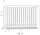
- Figures 1B , 1C and 1D are front side isometric, front isometric and underside views, respectively, of the air cleaner 100.
- Figure 1E is a top cross sectional view of the air cleaner 100 along the line 1E shown in Figure 1A .
- Figure 1F is an enlarged view of a portion of Figure 1E .
- the air cleaner 100 includes a corona electrode assembly or ionizing stage 110 and a collection electrode assembly or collecting stage 120 disposed in a housing 102.
- the housing 102 includes an inlet 103, an outlet 105 and a cavity 104 between the inlet and the outlet.
- the housing 102 includes a first side surface 106a, an upper surface 106b, a second side surface 106c, a rear surface portion 106d, an underside surface 106e, and a front surface portion 106f ( Figure 1C ). Portions of the surfaces 106a-f are hidden for clarity in Figures 1A through 1F .
- the housing 102 has a generally rectangular solid shape. In other embodiments, however, the housing 102 can be built or otherwise formed into any suitable shape (e.g., a cube, a hexagonal prism, a cylinder, etc.).
- the ionizing stage 110 is disposed within the housing 102 at least proximate the inlet 103 and comprises a plurality of corona electrodes 112 (e.g., electrically conductive wires, rods, plates, etc.).
- the corona electrodes 112 are arranged within the ionizing stage between a first terminal 113 and a second terminal 114.
- a plurality of individual apertures or slots 115 can receive and electrically couple the individual corona electrodes 112 to the second terminal 114.
- a plurality of exciting electrodes 116 are positioned between the corona electrodes 112 and the inlet 103.
- the first terminal 113 and the second terminal 114 can be electrically connected to a power source (e.g., a high voltage electrical power source) to produce an electrical field having a relatively high electrical potential difference (e.g., 5kV, 10kV, 20kV, etc.) between the corona electrodes 112 and the exciting electrodes 116.
- a power source e.g., a high voltage electrical power source
- the corona electrodes 112 can be configured to operate at +5kV while the exciting electrodes 116 can be configured operate at ground.
- both the corona electrodes 112 and the exciting electrodes 116 can be configured to operate at any number of suitable electrical potentials.
- the ionizing stage 110 in the illustrated embodiment includes the corona electrodes 112
- the ionizing stage 110 may include any suitable means of ionizing molecules (e.g., a laser, an electrospray ionizer, a thermospray ionizer, a sonic spray ionizer, a chemical ionizer, a quantum ionizer, etc.).
- the exciting electrodes 116 have a first diameter greater than (e.g., approximately twenty times larger) a second diameter of the corona electrodes 112. In other embodiments, however, the first diameter and second diameter can be any suitable size.
- the collecting stage 120 is disposed in the cavity between the ionizing stage 110 and the outlet 105.
- the collecting stage 120 includes a plurality of collecting electrodes 122 and a plurality of repelling electrodes 128.
- the collecting electrodes 122 and the repelling electrodes 128 are arranged in alternating rows within the collecting stage 120. In other examples, however, the collecting electrodes 122 and the repelling electrodes 128 may be positioned within the collecting stage 120 in any suitable arrangement.
- Each of the collecting electrodes 122 includes a first collecting portion 124 having a first outer surface 123a opposing a second outer surface 123b, and an internal conductive portion 125 disposed therebetween. At least one of the first outer surface 123a and the second outer surface 123b is arranged to be generally parallel with a flow of a gas (e.g., air) entering the cavity 104 via the inlet 103.
- a gas e.g., air
- the first collecting portion 124 is configured to receive and collect and receive particulate matter (e.g., particles having a first dimension between 0.1 microns and 1 mm, between 0.3 microns and 10 microns, between 0.3 microns and 25 microns and/or between 100 microns and 1 mm), and comprises an open-cell porous material such as, for example, a melamine foam (e.g., formaldehyde-melamine-sodium bisulfite copolymer), a melamine resin, a reticulated foam, a nanoporous material, a thermoset polymer, a polyurethanes, a polyethylene, etc.
- particulate matter e.g., particles having a first dimension between 0.1 microns and 1 mm, between 0.3 microns and 10 microns, between 0.3 microns and 25 microns and/or between 100 microns and 1 mm
- an open-cell porous material such as, for example, a melamine
- an open-cell porous material can lead to a substantial increase (e.g., a tenfold increase, a thousandfold increase, etc.) in the effective surface area of the collecting electrodes 122 compared to, for example, a smooth metal electrode that may be found in conventional electronic air cleaners.
- the open-cell porous material can receive and collect particulate matter (dust, dirt, contaminants, etc.) within the material, thereby reducing accumulation of particulate matter on the outer surfaces 123a and 123b, as well as limiting the maximum size of agglomerates that may form from the collected particulates based on the size of a first dimension of the cells in the porous material (e.g., from about 1 micron to about 1000 microns, from about 200 microns to about 500 microns, from about 140 microns to about 180 microns, etc.)
- the open-cell porous material can be made of a non-flammable material to reduce the risk of fire from, for example, a spark (e.g., a corona discharge from one of the corona electrodes 112).
- the open-cell porous material is also made from a material having a high electrical resistivity greater than 10 2 ⁇ -m (e.g., greater than or equal to 1 x 10 7 ⁇ -m, 1 x 10 9 ⁇ -m, 1 x 10 11 ⁇ -m, etc.)
- a high resistivity material e.g., between 10 2 and 10 9 Ohm-m, etc.
- the first collecting portion 124 may also include a disinfecting material (e.g., TiO 2 ) and/or a material (e.g., MnO 2 , a thermal oxidizer, a catalytic oxidizer, etc.) selected to reduce and/or neutralize volatile organic compounds (e.g., ozone, formaldehyde, paint fumes, CFCs, benzene, methylene chloride, etc.).
- a disinfecting material e.g., TiO 2
- a material e.g., MnO 2 , a thermal oxidizer, a catalytic oxidizer, etc.
- volatile organic compounds e.g., ozone, formaldehyde, paint fumes, CFCs, benzene, methylene chloride, etc.
- the first collecting portion 124 may include one or more nanoporous membranes and/or materials (e.g., manganese oxide, nanoporous gold, nanoporous silver, nanotubes, nanoporous silicon, nanoporous polycarbonate, zeolites, silica aerogels, activated carbon, graphene, etc.) having pore sizes ranging from, for example, 0.1 nm-1000nm.
- the first collecting portion 124 (comprising, e.g., one or more of the nanoporous materials above) may be configured to detect a composition of the particulate matter accumulated within the collecting electrodes 122.
- a voltage can be applied across the first collecting portion 124 and various types of particulate matter may be detected by monitoring, for example, changes in an ionic current passing therethrough. If a particle of interest (e.g., a toxin, a harmful pathogen, etc.) is detected, then an operator of a facility control system (not shown) coupled to the air cleaner 100 can be alerted.
- a particle of interest e.g., a toxin, a harmful pathogen, etc.
- the first collecting portion 124 may be made of a substantially rigid material.
- elastic or other tension-based mounting members are not necessary for securing the first collection portion 1224 within the cavity.
- the rigidity of the material in these embodiments may be sufficient to substantially support itself in a vertical direction within the cavity.
- an internal conductive portion 125 is not included in the collecting electrodes 122, wherein material itself is sufficiently conductive to carry the requisite charge.
- the material may include one or more of the conductive materials or compositions listed above.
- the internal conductive portion 125 can include a conductive surface or plate (e.g., a metal plate) sandwiched between opposing layers of the first collecting portion 124 and adhered thereto via an adhesive (e.g., cyanoacrylate, an epoxy, and/or another suitable bonding agent).
- an adhesive e.g., cyanoacrylate, an epoxy, and/or another suitable bonding agent.
- the internal conductive portion 125 can comprise any suitable conductive material or structure such as, for example, a metal plate, a metal grid, a conductive film (e.g., a metalized Mylar film), a conductive epoxy, conductive ink, and/or a plurality of conductive particles (e.g., a carbon powder, nanoparticles, etc.) distributed throughout the collecting electrodes 122.
- a coupling structure or terminal 126 can couple the internal conductive portion 125 of each of the collecting electrodes 122 to an electrical power source (not shown).
- a coupling structure or terminal 129 can couple each of the repelling electrodes 128 to an electrical power source (not shown).
- the collecting electrodes 122 may be configured to operate, for example, at a first electrical potential different from a second electrical potential of the repelling electrodes 128 when connected to the electrical power source.
- the internal conductive portion 125 can be configured operate at a greater electrical potential than either the first outer surface 123a or the second outer surface 123b of the individual collecting electrodes.
- the internal conductive portion 125 may be configured to have a first electrical conductivity greater than a second electrical conductivity of first collecting portion 124. Accordingly, the first outer surface 123a and/or the second outer surface 123b may have a first electrical potential less than a second electrical potential at the internal conductive portion 125. A difference between the first and second electrical potentials, for example, can attract charged particles into the first collecting portion 124 toward the internal conductive portion 125. In some embodiments, for example, the outer surfaces 123a and 123b have a second electrical conductivity lower than the first electrical conductivity.
- the air cleaner 100 can receive electric power from a power source (not shown) coupled to the corona electrodes 112, the exciting electrodes 116, the collecting electrodes 122, and the repelling electrodes 128.
- the individual corona electrodes 112 can receive, for example, a high voltage (e.g., 10kV, 20kV, etc.) and emit ions resulting in an electric current proximate the individual corona electrodes 112 and flowing toward the exciting electrodes 116 or/and the collecting electrodes 122.
- the corona discharges can ionize gas molecules (e.g., air molecules) in the incoming gas (e.g., air) entering the housing 102 and the cavity 104 through the inlet 103.
- particulate matter e.g., dust, ash, pathogens, spores, etc.
- the repelling electrodes 128 can repel or otherwise direct the charged particulate matter toward adjacent collecting electrodes 122 due to a difference in electrical potential and/or a difference in electrical charge between the repelling electrodes 128 and the collecting electrodes 122.
- the repelling electrodes 128 may also include a means for aerodynamically directing charged particulate matter toward adjacent collecting electrodes 122.
- the corona electrodes 112, the collecting electrodes 122, and the repelling electrodes 128 can be configured to operate at any suitable electrical potential or voltage relative to each other.
- the corona electrodes 112, the collecting electrodes 122, and the repelling electrodes 128 can all have a first electrical charge, but may also be configured to have first, second, third, and fourth voltages, respectively.
- a difference between the first, second, third and fourth voltage can determine a path that one or more charged particles (e.g., charged particulate matter) through the ionizing stage 110.
- the collecting electrodes 122 and the exciting electrodes 116 may be grounded, while the corona electrodes may have an electrical potential between, for example, 4kV and 10 kV and the repelling electrodes 128 may have an electrical potential between, for example, 6kV and 20 kV.
- portions of the collecting electrodes 122 may have different electrical potentials relative to other portions.
- the internal conductive portion 125 may have a different electrical potential (e.g., a higher electrical potential) than the corresponding first outer surface 123a or second outer surface 123b, thereby creating an electric field within the collecting portion 124.
- the electrical potential difference between the internal conductive portion 125 and the corresponding first outer surface 123a and/or second outer surface 123b may be caused by a portion of an ionic current flowing from an adjacent repelling electrode 128.
- This potential difference creates the electric field E in the body of the porous material.
- a charged particle may penetrate deep into the porous material (e.g., the collecting portion 124) where it remains. Accordingly, charged particulate matter may not only be directed and/or repelled toward the internal conductive portion 125 of the collecting electrodes 122, but may also be received, collected, and/or absorbed into the first collecting portion 124 of the individual collecting electrodes 122. As a result, particulate matter does not merely accumulate and/or adhere to the outer surfaces 123a and 123b, but is instead received and collected into the first collecting portion 124.
- the porous material resistivity has a specific resistivity that allows the ionic current flow to the internal conductive portion 125 (i.e., should be slightly electrically conductive).
- the porous material can have a resistance on the order of Megaohms to prevent spark discharge between the collecting and the repelling electrodes.
- the strength of the electric field E can be adjustable in response to the relative size of the cells in the porous material (e.g., the collection portion 124).
- the electric field E needed to absorb particles into the collection portion 124 may be proportional to the cell size.
- the strength of the electric field E can have a first value when the cells of the collection portion 124 have a first size (e.g., a diameter of approximately 150 microns).
- the strength of the electric field E can have a second value (e.g., a value greater than the first value) when the cells of the collecting portion 124 have a second size (e.g., a diameter of approximately 400 microns) to retain larger size particles accumulated therein.
- the internal conductive portion 125 of the collecting electrodes 122 can be configured operate at an electrical potential different from either the first outer surface 123a or the second outer surface 123b of the individual collecting electrodes 122. Accordingly, charged particulate matter may not only be directed and/or repelled toward the internal conductive portion 125 of the collecting electrodes 122, but may also be received, collected, and/or absorbed into the first collecting portion 124 of the individual collecting electrodes 122. As a result, particulate matter does not merely accumulate and/or adhere to the outer surfaces 123a and 123b, but is instead received and collected into the first collecting portion 124.
- an open cell porous material in the first collecting portion 124 can provide a significant increase (e.g., 1000 times greater) in a collection surface area of the individual collecting electrodes 122 compared to embodiments without an open-cell porous media (e.g., collecting electrodes comprising metal plates).
- the collecting electrodes 122 are arranged generally parallel to the gas flow entering the housing 102, particulate matter in the gas can be removed with minimal pressure drop across the air cleaner 100 compared to conventional filters having fibrous media through which airflow is directed (e.g., HEPA filters).
- the collecting electrodes 122 can be configured to be removable (and/or disposable) and replaced with different collecting electrodes 122.
- the collecting electrodes 122 can be configured such that the used or saturated first collecting portion 124 can be removed from the internal conductive portion 125 and discarded, to be replaced by a new clean collecting portion 124, thereby refurbishing the collecting electrodes 122 for continued used without discarding the internal conductive portion 125.
- One feature of the present technology is that replacing or refurbishing the collecting electrodes 122 is expected to be more cost effective than replacing electrodes made entirely or substantially of metal.
- the replaceability and disposability of the collecting electrodes 122, or the first collecting portion 124 thereof facilitates removal of collected pathogens and contaminants from the system itself, and is expected to minimize the need for frequent cleaning. Furthermore, the present technology allows the filtering and/or cleaning of small particles in commercial HVAC systems without the need for adding a conductive fluid to the collecting electrodes 122.
- FIG 2A is a schematic top view of an electronic air cleaner 200.
- Figures 2B and 2C are top views of a repelling electrode 228 configured in accordance with one or more embodiments of the present technology.
- the air cleaner 200 comprises a collecting stage 220 and a plurality of flashing portions 230.
- the individual flashing portions 230 can be disposed on either side of the collecting stage 220 to prevent air and/or particulate matter from passing through the collecting stage 220 without flowing adjacent one of the collecting electrodes 122.
- the collecting stage 220 further includes a plurality of repelling electrodes 228.
- the repelling electrodes 228 each have a proximal portion 261, a distal portion 262 and an intermediate portion 263 therebetween.
- a first projection 264a, disposed on the proximal portion 261, and a second projection 264b, disposed on the distal portion 262, can be configured, for example, to electrically repel charged particles (e.g., particulate matter in a gas flow), toward adjacent collecting electrodes 122.
- the first and second projections 264a and 264b may also be configured to aerodynamically guide or otherwise direct particulate matter in the gas flow toward an adjacent collecting electrode 122.
- the first projection 264a can have a first width Wi and the second projection 264b can have a second width W 2 .
- the first width Wi and the second width W 2 are generally the same. In other embodiments, however, the first width Wi may be different from (e.g., less than) the second width W 2 .
- the first and second projections 264a and 264b have a generally round shape.
- a first projection 266a and a second projection 266b can have a generally rectangular shape instead.
- the projections may have any suitable shape (e.g., triangular, trapezoidal, etc.).
- the air filter 200 further includes a ground stage 236 disposed within the housing 102 between the ionizing stage 110 and the inlet 103.
- the ground stage 236 can be configured operate at a ground potential relative to the ionizing stage 110.
- the ground stage 236 can also serve as a physical barrier to prevent objects (e.g., an operator's hand or fingers) from entering the air filter, thereby preventing injury and/or electric shock to the inserted objects.
- the ground stage 236 can include, for example, a metal grid, a mesh, a sheet having a plurality of apertures, etc.
- the ground stage 236 can include openings, holes, and/or apertures approximately 1/2" inch to 1/8" (e.g., 1/4" inch) to prevent fingers from entering the cavity 104. In other embodiments, however, the ground stage 236 can include openings of any suitable size.
- one or more occupation or proximity sensors 238 connected to an electrical power source may be disposed proximate the inlet 103 as an additional safety feature.
- the proximity sensors 238 can be configured to, for example, automatically disconnect electrical power to the ionizing stage 110 and/or the collecting stage 120.
- the proximity sensor 238 can also be configured to alert a facility control system (not shown) upon detection of an inserted object.
- a fluid distributor, nebulizer or spray component 239 may be disposed at least proximate the inlet 103.
- the spray component 239 can configured to deliver an aerosol or liquid 240 (e.g., water) into the gas flow entering the air filter 200.
- the liquid 240 can enter the cavity 104 and be distributed toward the collecting stage 220. At the collecting stage 220, the liquid 240 can be absorbed by the first collecting portion 124.
- the liquid 240 e.g., water
- the liquid 240 can regulate and modify the first electrical resistivity of the first collecting portion 124.
- a control system and/or an operator can monitor an electric current between the collecting electrodes 122 and the repelling electrodes 228. If, for example, the electric current falls below a predetermined threshold (e.g., 1 microampere), the spray component 239 can be manually or automatically activated to deliver the liquid 240 toward the collecting stage 220. In other embodiments, for example, the spray component 239 can be activated to increase the effectiveness of one or more materials in the first collecting portion 124. Titanium dioxide, for example, can be more effective in killing pathogens (e.g., bacteria) when wet.
- pathogens e.g., bacteria
- FIG 3 is a schematic top view of an air filter 300 configured in accordance with an embodiment of the present technology.
- the air filter 300 includes an ionizing stage 310 having a plurality of corona electrodes 312 (e.g., analogous to the corona electrodes 112 of Figure 1A ).
- the air filter 300 further includes a collection stage includes the repelling electrodes 228 ( Figures 2A-2C ) and a plurality of collecting electrodes 322.
- a proximal portion 351 of the individual collecting electrodes 322 includes a first conductive portion 325 between a first outer surface 323a and an opposing second outer surface 323b.
- the first and second outer surfaces 323a and 323b can be positioned in the collecting stage 320 generally parallel to an airflow direction through the air filter 300. At least a portion of the first and second outer surfaces 323a and 323b can include a first collecting portion 324 (e.g., analogous to the first collecting portion 124 of Figure 1A ) comprising, for example, a first open-cell, porous material (e.g., a melamine foam or other suitable material).
- a first collecting portion 324 e.g., analogous to the first collecting portion 124 of Figure 1A
- a first open-cell, porous material e.g., a melamine foam or other suitable material.
- a proximal portion 351 of the individual collecting electrodes 322 includes a second collecting portion 352 and a second conductive portion 354.
- the second collecting portion 352 includes a second material having an open cell structure (e.g., a melamine foam, etc.) and having a high resistivity, greater than 10 2 ⁇ -m (e.g., greater than 1 x 10 9 ⁇ -m) and can prevent sparking or another discharge from the corona electrodes 312 during operation.
- the second conductive portion 354 can further attract charged particles to the collecting electrode 322.
- the second conductive portion 354 (e.g., a tube or any other suitable shape) can include a second conductive material (e.g., metal, carbon powder, and/or any other suitable conductor) having second electrical resistivity different from a first electrical resistivity of the first material of the first collecting portion 324. While the first collecting portion 324 and the second conductive portion 354 may have different electrical resistivities, in other embodiments they may have generally the same electrical potential. In some embodiments, having materials of different electrical resistivities at the same electrical potential is expected to lower a spark over between the corona electrodes 312 and the collecting electrodes 322.
- a second conductive material e.g., metal, carbon powder, and/or any other suitable conductor
- FIGS 4A and 4B are side views of an ionization stage 410 shown in a first configuration and a second configuration, respectively, in accordance with an embodiment of the present technology.
- the ionization stage 410 includes a plurality of electrodes 412 (e.g., the corona electrodes 112 of Figure 1A ).
- Each of the electrodes 412 includes a cleaning device 470 configured to clean and/or remove accumulated matter (e.g., oxidation byproducts, silicon dioxide, etc.) along an outer surface of the electrodes 412.
- the cleaning device 470 includes a plurality of propeller blades 472 circumferentially arranged around a center portion 474 having a bore 476 therethrough.
- the bore 476 includes an interior surface 477 configured to clean or otherwise engage the corresponding electrode 412.
- the ionization stage 410 can be configured to be positioned in an airflow path (e.g. in the housing 102 of the air cleaner 100 of Figure 1A ).
- the airflow can propel the blades 472 and lift the cleaning device 470 upward along the electrode 412.
- the interior surface 477 engages the electrode 412, thereby removing at least a portion of the accumulated matter.
- a moveable stopper 480 can engage the cleaning device 470, thereby hindering further ascension of the electrode 412 ( Figure 4B ).
- the cleaning device 470 may return to the position shown in Figure 4A , thereby allowing the cleaning device 470 to continue cleaning the electrode 412.
- the stopper 480 may have a shape of a leaf (or any other suitable shape, such as a square, rectangle, etc.) that is initially in a first configuration (e.g., a vertical configuration as shown, for example, in Figure 4A ). In response to the force of an airflow, the stopper 480 may move from the first configuration to a second configuration (e.g., a substantially horizontal configuration as shown, for example, in Figure 4B ). When the cleaning device 470 reaches the upper extent of the electrode 412, its rotation is hindered by the stopper 480 ( Figure 4B ). The stopper 480 may remain in the second configuration as long as the airflow maintains an adequate pushing or lift force thereon. When the airflow ceases, however, the stopper 480 returns to the first configuration thereby releasing the cleaning device 470 and allowing the cleaning device 470 to return to the initial position shown in Figure 4A , remaining there until receiving sufficient airflow for another cleaning cycle.
- a first configuration e.g., a vertical configuration as shown,
Landscapes
- Engineering & Computer Science (AREA)
- Chemical & Material Sciences (AREA)
- Combustion & Propulsion (AREA)
- Mechanical Engineering (AREA)
- General Engineering & Computer Science (AREA)
- Automation & Control Theory (AREA)
- Ceramic Engineering (AREA)
- Electrostatic Separation (AREA)
- Disinfection, Sterilisation Or Deodorisation Of Air (AREA)
Description
- This application claims the benefit of pending
U.S. Provisional Application No. 61/647,045, filed May 15, 2012 - The present technology relates generally to cleaning gas flows using electrostatic filters and associated systems and methods. In particular, several embodiments are directed toward electronic air cleaners for use in heating, air-conditioning, and ventilation (HVAC) systems having collection electrodes lined with a collection material having an open-cell structure, although these or similar embodiments may also be used in cleaning systems for other types of gases, in industrial electrostatic precipitators, and/or in other forms of electrostatic filtration.
- The most common types of residential or commercial HVAC air filters employ a fibrous filter media (made from polyester fibers, glass fibers or microfibers, etc.) placed substantially perpendicular to the airflow through which air may pass (e.g., an air conditioner filter, a HEPA filter, etc.) such that particles are removed from the air mechanically (coming into contact with one or more fibers and either adhering to or being blocked by the fibers); some of these filters are also electrostatically charged (either passively during use, or actively during manufacture) to increase the chances of particles coming into contact and staying adhered to the fibers.
- Another form of air filter is known as an electronic air cleaner (EAC). A conventional EAC includes one or more corona electrodes and one or more smooth metal collecting electrode plates that are substantially parallel to the airflow. The corona electrodes produce a corona discharge that ionizes air molecules in an airflow received into the filter. The ionized air molecules impart a net charge to nearby particles (e.g., dust, dirt, contaminants etc.) in the airflow. The charged particles are subsequently electrostatically attracted to one of the collecting electrode plates and thereby removed from the airflow as the air moves past the collecting electrode plates. After a sufficient amount of air passes through the filter, the collecting electrodes can accumulate a layer of particles and dust and eventually need to be cleaned. Cleaning intervals may vary from, for example, thirty minutes to several days. Further, since the particles are on an outer surface of the collecting electrodes, they may become re-entrained in the airflow since a force of the airflow may exceed the electric force attracting the charged particles to the collecting electrodes, especially if many particles agglomerate through attraction to each other, thereby reducing the net attraction to the collector plate. Such agglomeration and re-entrainment may require use of a media afterfilter placed downstream and substantially perpendicular to the airflow, thereby increasing airflow resistance. Another limitation of conventional EACs is that corona wires can become contaminated by oxidation or other deposits during operation, thereby lowering their effectiveness and necessitating frequent cleaning. Moreover, the corona discharge can produce a significant amount of contaminants such as, for example, ozone, which may necessitate an implementation of activated carbon filters placed substantially perpendicular to the airflow that can increase airflow resistance.
- While fibrous media filters do not produce ozone, they typically have to be cleaned and/or replaced regularly due to an accumulation of particles. Furthermore, fibrous media filters are placed substantially perpendicular to the airflow, increasing airflow resistance and causing a significant static pressure differential across the filter, which increases as more particles accumulate or collect in the filter. Pressure drop across various components of an HVAC system is a constant concern for designers and operators of mechanical air systems, since it either slows the airflow or increases the amount of energy required to move the air through the system. Accordingly, there exists a need for an air filter capable of relatively long intervals between cleaning and/or replacement and a relatively low pressure drop across the filter after installation in an HVAC system.
-
DE2854742 discloses an electrostatic filter which separates contaminant particles from dust laden media by passing them between two parallel electrode separator plates. In a first (ionisation) stage, the particles are charged by ionisation opposite to the charge on the separator electrodes. In the second (separation) stage, the electrodes are lined with an activated carbon layer over an insulating film. This removes even odoriferous matter from the filtered gas stream and firmly retains all separated particles. It offers a negligibly small resistance to the gas flow. -
DE19859827 discloses a process for treating pollutants in electrofilter systems. The process comprises directing ions produced by a spray electrode in the direction of a highly conducting material. The pollutants have ions covering them, and form a coating on the electrodes, which consist of pins and are porous. -
-
Figure 1A is a rear isometric view of an EAC configured in accordance with embodiments of the present technology.Figures 1B ,1C and1D are side isometric, front isometric and underside views, respectively, of the EAC ofFigure 1A .Figure 1E is a top cross sectional view ofFigure 1A along aline 1E.Figure 1F is an enlarged view of a portion ofFigure 1E . -
Figure 2A is a schematic top view of an EAC configured in accordance with embodiments of the present technology.Figures 2B and 2C are schematic top views of repelling electrodes configured in accordance with an embodiment of the present technology. -
Figure 3 is a schematic top view of a portion of an air filter configured in accordance with an embodiment of the present technology. -
Figures 4A and 4B are side views of an ionization stage shown in a first configuration and a second configuration, respectively, in accordance with an embodiment of the present technology. - The present technology relates to an electrostatic precipitator electrode assembly to be positioned in an air filter, the assembly comprising: one or more collecting electrodes each comprising: an internal conductive portion and an outer surface generally parallel with an airflow direction through the air filter, and wherein the collecting electrodes further include a collecting portion, and wherein said collecting portion exhibits an open cell structure having a high electrical resistivity greater than 102 Ωm.
- Certain specific details are set forth in the following description and in
Figures 1A-4B to provide a thorough understanding of various embodiments of the technology. Other details describing well-known structures and systems often associated with electronic air cleaners and associated devices have not been set forth in the following technology to avoid unnecessarily obscuring the description of the various embodiments of the technology. A person of ordinary skill in the art, therefore, will accordingly understand that the technology may have other embodiments with additional elements, or the technology may have other embodiments without several of the features shown and described below with reference toFigures 1A-4B . -
Figure 1A is a rear isometric view of anelectronic air cleaner 100.Figures 1B ,1C and1D are front side isometric, front isometric and underside views, respectively, of theair cleaner 100.Figure 1E is a top cross sectional view of theair cleaner 100 along theline 1E shown inFigure 1A .Figure 1F is an enlarged view of a portion ofFigure 1E . Referring toFigures 1A through 1F together, theair cleaner 100 includes a corona electrode assembly or ionizingstage 110 and a collection electrode assembly or collectingstage 120 disposed in ahousing 102. Thehousing 102 includes aninlet 103, anoutlet 105 and acavity 104 between the inlet and the outlet. Thehousing 102 includes afirst side surface 106a, anupper surface 106b, asecond side surface 106c, arear surface portion 106d, anunderside surface 106e, and a front surface portion 106f (Figure 1C ). Portions of thesurfaces 106a-f are hidden for clarity inFigures 1A through 1F . In the illustrated embodiment, thehousing 102 has a generally rectangular solid shape. In other embodiments, however, thehousing 102 can be built or otherwise formed into any suitable shape (e.g., a cube, a hexagonal prism, a cylinder, etc.). - The ionizing
stage 110 is disposed within thehousing 102 at least proximate theinlet 103 and comprises a plurality of corona electrodes 112 (e.g., electrically conductive wires, rods, plates, etc.). Thecorona electrodes 112 are arranged within the ionizing stage between afirst terminal 113 and asecond terminal 114. A plurality of individual apertures orslots 115 can receive and electrically couple theindividual corona electrodes 112 to thesecond terminal 114. A plurality ofexciting electrodes 116 are positioned between thecorona electrodes 112 and theinlet 103. Thefirst terminal 113 and thesecond terminal 114 can be electrically connected to a power source (e.g., a high voltage electrical power source) to produce an electrical field having a relatively high electrical potential difference (e.g., 5kV, 10kV, 20kV, etc.) between thecorona electrodes 112 and theexciting electrodes 116. In one embodiment, for example, thecorona electrodes 112 can be configured to operate at +5kV while theexciting electrodes 116 can be configured operate at ground. In other embodiments, however, both thecorona electrodes 112 and theexciting electrodes 116 can be configured to operate at any number of suitable electrical potentials. Moreover, while the ionizingstage 110 in the illustrated embodiment includes thecorona electrodes 112, in other embodiments the ionizingstage 110 may include any suitable means of ionizing molecules (e.g., a laser, an electrospray ionizer, a thermospray ionizer, a sonic spray ionizer, a chemical ionizer, a quantum ionizer, etc.). Furthermore, in the illustrated embodiment ofFigures 1A-1F , theexciting electrodes 116 have a first diameter greater than (e.g., approximately twenty times larger) a second diameter of thecorona electrodes 112. In other embodiments, however, the first diameter and second diameter can be any suitable size. - The
collecting stage 120 is disposed in the cavity between the ionizingstage 110 and theoutlet 105. The collectingstage 120 includes a plurality of collectingelectrodes 122 and a plurality of repellingelectrodes 128. In the illustrated embodiments ofFigures 1A-1F , the collectingelectrodes 122 and the repellingelectrodes 128 are arranged in alternating rows within the collectingstage 120. In other examples, however, the collectingelectrodes 122 and the repellingelectrodes 128 may be positioned within the collectingstage 120 in any suitable arrangement. - Each of the collecting
electrodes 122 includes afirst collecting portion 124 having a firstouter surface 123a opposing a secondouter surface 123b, and an internalconductive portion 125 disposed therebetween. At least one of the firstouter surface 123a and the secondouter surface 123b is arranged to be generally parallel with a flow of a gas (e.g., air) entering thecavity 104 via theinlet 103. Thefirst collecting portion 124 is configured to receive and collect and receive particulate matter (e.g., particles having a first dimension between 0.1 microns and 1 mm, between 0.3 microns and 10 microns, between 0.3 microns and 25 microns and/or between 100 microns and 1 mm), and comprises an open-cell porous material such as, for example, a melamine foam (e.g., formaldehyde-melamine-sodium bisulfite copolymer), a melamine resin, a reticulated foam, a nanoporous material, a thermoset polymer, a polyurethanes, a polyethylene, etc. The use of an open-cell porous material can lead to a substantial increase (e.g., a tenfold increase, a thousandfold increase, etc.) in the effective surface area of the collectingelectrodes 122 compared to, for example, a smooth metal electrode that may be found in conventional electronic air cleaners. Moreover, the open-cell porous material can receive and collect particulate matter (dust, dirt, contaminants, etc.) within the material, thereby reducing accumulation of particulate matter on theouter surfaces first collecting portion 124 can reduce, for example, a likelihood of a corona discharge between the corona electrodes and the collectingelectrodes 122 or a spark over between the collectingelectrode 122 and the repellingelectrode 128. In some embodiments, thefirst collecting portion 124 may also include a disinfecting material (e.g., TiO2) and/or a material (e.g., MnO2, a thermal oxidizer, a catalytic oxidizer, etc.) selected to reduce and/or neutralize volatile organic compounds (e.g., ozone, formaldehyde, paint fumes, CFCs, benzene, methylene chloride, etc.). In other embodiments, thefirst collecting portion 124 may include one or more nanoporous membranes and/or materials (e.g., manganese oxide, nanoporous gold, nanoporous silver, nanotubes, nanoporous silicon, nanoporous polycarbonate, zeolites, silica aerogels, activated carbon, graphene, etc.) having pore sizes ranging from, for example, 0.1 nm-1000nm. In some further embodiments, the first collecting portion 124 (comprising, e.g., one or more of the nanoporous materials above) may be configured to detect a composition of the particulate matter accumulated within the collectingelectrodes 122. In these embodiments, a voltage can be applied across thefirst collecting portion 124 and various types of particulate matter may be detected by monitoring, for example, changes in an ionic current passing therethrough. If a particle of interest (e.g., a toxin, a harmful pathogen, etc.) is detected, then an operator of a facility control system (not shown) coupled to theair cleaner 100 can be alerted. - In some embodiments, the
first collecting portion 124 may be made of a substantially rigid material. In certain of these embodiments, elastic or other tension-based mounting members are not necessary for securing the first collection portion 1224 within the cavity. For example, the rigidity of the material in these embodiments may be sufficient to substantially support itself in a vertical direction within the cavity. In certain of these embodiments, an internalconductive portion 125 is not included in the collectingelectrodes 122, wherein material itself is sufficiently conductive to carry the requisite charge. In such embodiments, the material may include one or more of the conductive materials or compositions listed above. - Referring to
Figure 1F , the internalconductive portion 125 can include a conductive surface or plate (e.g., a metal plate) sandwiched between opposing layers of thefirst collecting portion 124 and adhered thereto via an adhesive (e.g., cyanoacrylate, an epoxy, and/or another suitable bonding agent). In other embodiments, however, the internalconductive portion 125 can comprise any suitable conductive material or structure such as, for example, a metal plate, a metal grid, a conductive film (e.g., a metalized Mylar film), a conductive epoxy, conductive ink, and/or a plurality of conductive particles (e.g., a carbon powder, nanoparticles, etc.) distributed throughout the collectingelectrodes 122. A coupling structure or terminal 126 can couple the internalconductive portion 125 of each of the collectingelectrodes 122 to an electrical power source (not shown). Similarly, a coupling structure or terminal 129 can couple each of the repellingelectrodes 128 to an electrical power source (not shown). The collectingelectrodes 122 may be configured to operate, for example, at a first electrical potential different from a second electrical potential of the repellingelectrodes 128 when connected to the electrical power source. Furthermore, withinindividual collecting electrodes 122, the internalconductive portion 125 can be configured operate at a greater electrical potential than either the firstouter surface 123a or the secondouter surface 123b of the individual collecting electrodes. In some embodiments, for example, the internalconductive portion 125 may be configured to have a first electrical conductivity greater than a second electrical conductivity of first collectingportion 124. Accordingly, the firstouter surface 123a and/or the secondouter surface 123b may have a first electrical potential less than a second electrical potential at the internalconductive portion 125. A difference between the first and second electrical potentials, for example, can attract charged particles into thefirst collecting portion 124 toward the internalconductive portion 125. In some embodiments, for example, theouter surfaces - In operation, the
air cleaner 100 can receive electric power from a power source (not shown) coupled to thecorona electrodes 112, theexciting electrodes 116, the collectingelectrodes 122, and the repellingelectrodes 128. Theindividual corona electrodes 112 can receive, for example, a high voltage (e.g., 10kV, 20kV, etc.) and emit ions resulting in an electric current proximate theindividual corona electrodes 112 and flowing toward theexciting electrodes 116 or/and the collectingelectrodes 122. The corona discharges can ionize gas molecules (e.g., air molecules) in the incoming gas (e.g., air) entering thehousing 102 and thecavity 104 through theinlet 103. As the ionized gas molecules collide with and charge incoming particulate matter that flows from theionizing stage 110 toward the collectingstage 120, particulate matter (e.g., dust, ash, pathogens, spores, etc.) in the gas can be electrically attracted to and, thus, electrically coupled to the collectingelectrodes 122. The repellingelectrodes 128 can repel or otherwise direct the charged particulate matter toward adjacent collectingelectrodes 122 due to a difference in electrical potential and/or a difference in electrical charge between the repellingelectrodes 128 and the collectingelectrodes 122. As described in further detail below with reference toFigures 2B and 2C , the repellingelectrodes 128 may also include a means for aerodynamically directing charged particulate matter toward adjacent collectingelectrodes 122. - The
corona electrodes 112, the collectingelectrodes 122, and the repellingelectrodes 128 can be configured to operate at any suitable electrical potential or voltage relative to each other. In some embodiments, for example, thecorona electrodes 112, the collectingelectrodes 122, and the repellingelectrodes 128 can all have a first electrical charge, but may also be configured to have first, second, third, and fourth voltages, respectively. A difference between the first, second, third and fourth voltage can determine a path that one or more charged particles (e.g., charged particulate matter) through theionizing stage 110. For instance, the collectingelectrodes 122 and theexciting electrodes 116 may be grounded, while the corona electrodes may have an electrical potential between, for example, 4kV and 10 kV and the repellingelectrodes 128 may have an electrical potential between, for example, 6kV and 20 kV. Moreover, portions of the collectingelectrodes 122 may have different electrical potentials relative to other portions. For example, in one or moreindividual collecting electrodes 122, the internalconductive portion 125 may have a different electrical potential (e.g., a higher electrical potential) than the corresponding firstouter surface 123a or secondouter surface 123b, thereby creating an electric field within the collectingportion 124. - As those of ordinary skill in the art will appreciate, the electrical potential difference between the internal
conductive portion 125 and the corresponding firstouter surface 123a and/or secondouter surface 123b may be caused by a portion of an ionic current flowing from anadjacent repelling electrode 128. When this ionic current Ii flows through the porous material (e.g., the collecting portion 124) that has a relatively high electrical resistance Rpor (e.g., between 20 Megaohms and 2 Gigaohms) it creates certain potential difference Vdif described by Ohm's law: Vdif = Ii x Rpor. This potential difference creates the electric field E in the body of the porous material. A charged particle (e.g., particulate matter) in this electric field E is subject to the Coulombic force F of the field E described by:
F = q * E, where q is the particle electrical charge. - Under this force F, a charged particle may penetrate deep into the porous material (e.g., the collecting portion 124) where it remains. Accordingly, charged particulate matter may not only be directed and/or repelled toward the internal
conductive portion 125 of the collectingelectrodes 122, but may also be received, collected, and/or absorbed into thefirst collecting portion 124 of theindividual collecting electrodes 122. As a result, particulate matter does not merely accumulate and/or adhere to theouter surfaces first collecting portion 124. - In some embodiments, for example, the porous material resistivity has a specific resistivity that allows the ionic current flow to the internal conductive portion 125 (i.e., should be slightly electrically conductive). In these embodiments, for example, the porous material can have a resistance on the order of Megaohms to prevent spark discharge between the collecting and the repelling electrodes.
- In other embodiments, the strength of the electric field E can be adjustable in response to the relative size of the cells in the porous material (e.g., the collection portion 124). As those of ordinary skill in the art will appreciate, the electric field E needed to absorb particles into the
collection portion 124 may be proportional to the cell size. For example, the strength of the electric field E can have a first value when the cells of thecollection portion 124 have a first size (e.g., a diameter of approximately 150 microns). The strength of the electric field E can have a second value (e.g., a value greater than the first value) when the cells of the collectingportion 124 have a second size (e.g., a diameter of approximately 400 microns) to retain larger size particles accumulated therein. - As discussed above, the internal
conductive portion 125 of the collectingelectrodes 122 can be configured operate at an electrical potential different from either the firstouter surface 123a or the secondouter surface 123b of theindividual collecting electrodes 122. Accordingly, charged particulate matter may not only be directed and/or repelled toward the internalconductive portion 125 of the collectingelectrodes 122, but may also be received, collected, and/or absorbed into thefirst collecting portion 124 of theindividual collecting electrodes 122. As a result, particulate matter does not merely accumulate and/or adhere to theouter surfaces first collecting portion 124. As explained above, the use of an open cell porous material in thefirst collecting portion 124 can provide a significant increase (e.g., 1000 times greater) in a collection surface area of theindividual collecting electrodes 122 compared to embodiments without an open-cell porous media (e.g., collecting electrodes comprising metal plates). - Moreover, because the collecting
electrodes 122 are arranged generally parallel to the gas flow entering thehousing 102, particulate matter in the gas can be removed with minimal pressure drop across theair cleaner 100 compared to conventional filters having fibrous media through which airflow is directed (e.g., HEPA filters). - After a period of use of the
air cleaner 100, particulate matter can saturate thefirst collecting portion 124 of the individual collection electrodes. In some embodiments, the collectingelectrodes 122 can be configured to be removable (and/or disposable) and replaced withdifferent collecting electrodes 122. In other embodiments, the collectingelectrodes 122 can be configured such that the used or saturated first collectingportion 124 can be removed from the internalconductive portion 125 and discarded, to be replaced by a newclean collecting portion 124, thereby refurbishing the collectingelectrodes 122 for continued used without discarding the internalconductive portion 125. One feature of the present technology is that replacing or refurbishing the collectingelectrodes 122 is expected to be more cost effective than replacing electrodes made entirely or substantially of metal. Moreover, the replaceability and disposability of the collectingelectrodes 122, or thefirst collecting portion 124 thereof, facilitates removal of collected pathogens and contaminants from the system itself, and is expected to minimize the need for frequent cleaning. Furthermore, the present technology allows the filtering and/or cleaning of small particles in commercial HVAC systems without the need for adding a conductive fluid to the collectingelectrodes 122. -
Figure 2A is a schematic top view of anelectronic air cleaner 200.Figures 2B and 2C are top views of a repellingelectrode 228 configured in accordance with one or more embodiments of the present technology. Referring toFigures 2A-2C together, for example, theair cleaner 200 comprises a collectingstage 220 and a plurality of flashingportions 230. Theindividual flashing portions 230 can be disposed on either side of the collectingstage 220 to prevent air and/or particulate matter from passing through the collectingstage 220 without flowing adjacent one of the collectingelectrodes 122. The collectingstage 220 further includes a plurality of repellingelectrodes 228. The repellingelectrodes 228 each have aproximal portion 261, adistal portion 262 and anintermediate portion 263 therebetween. Afirst projection 264a, disposed on theproximal portion 261, and asecond projection 264b, disposed on thedistal portion 262, can be configured, for example, to electrically repel charged particles (e.g., particulate matter in a gas flow), toward adjacent collectingelectrodes 122. Moreover, the first andsecond projections adjacent collecting electrode 122. - As shown in
Figure 2B , thefirst projection 264a can have a first width Wi and thesecond projection 264b can have a second width W2. In the illustrated embodiment ofFigure 2B , the first width Wi and the second width W2 are generally the same. In other embodiments, however, the first width Wi may be different from (e.g., less than) the second width W2. Moreover, in the embodiment illustrated inFigure 2B , the first andsecond projections Figure 2C , however, afirst projection 266a and asecond projection 266b can have a generally rectangular shape instead. Further, in other embodiments, the projections may have any suitable shape (e.g., triangular, trapezoidal, etc.). - Referring again to
Figure 2A , theair filter 200 further includes aground stage 236 disposed within thehousing 102 between theionizing stage 110 and theinlet 103. Theground stage 236 can be configured operate at a ground potential relative to theionizing stage 110. Theground stage 236 can also serve as a physical barrier to prevent objects (e.g., an operator's hand or fingers) from entering the air filter, thereby preventing injury and/or electric shock to the inserted objects. Theground stage 236 can include, for example, a metal grid, a mesh, a sheet having a plurality of apertures, etc. In some embodiments, for example, theground stage 236 can include openings, holes, and/or apertures approximately 1/2" inch to 1/8" (e.g., 1/4" inch) to prevent fingers from entering thecavity 104. In other embodiments, however, theground stage 236 can include openings of any suitable size. - In certain embodiments, one or more occupation or
proximity sensors 238 connected to an electrical power source (not shown) may be disposed proximate theinlet 103 as an additional safety feature. Upon detection of an object (e.g., an operator's hand), theproximity sensors 238 can be configured to, for example, automatically disconnect electrical power to theionizing stage 110 and/or the collectingstage 120. In some embodiments, theproximity sensor 238 can also be configured to alert a facility control system (not shown) upon detection of an inserted object. - In certain embodiments, a fluid distributor, nebulizer or
spray component 239 may be disposed at least proximate theinlet 103. Thespray component 239 can configured to deliver an aerosol or liquid 240 (e.g., water) into the gas flow entering theair filter 200. The liquid 240 can enter thecavity 104 and be distributed toward the collectingstage 220. At the collectingstage 220, the liquid 240 can be absorbed by thefirst collecting portion 124. As those of ordinary skill in the art will appreciate, the liquid 240 (e.g., water) can regulate and modify the first electrical resistivity of thefirst collecting portion 124. In some embodiments, for example, a control system and/or an operator (not shown) can monitor an electric current between the collectingelectrodes 122 and the repellingelectrodes 228. If, for example, the electric current falls below a predetermined threshold (e.g., 1 microampere), thespray component 239 can be manually or automatically activated to deliver the liquid 240 toward the collectingstage 220. In other embodiments, for example, thespray component 239 can be activated to increase the effectiveness of one or more materials in thefirst collecting portion 124. Titanium dioxide, for example, can be more effective in killing pathogens (e.g., bacteria) when wet. -
Figure 3 is a schematic top view of anair filter 300 configured in accordance with an embodiment of the present technology. In the embodiment ofFigure 3 , theair filter 300 includes an ionizing stage 310 having a plurality of corona electrodes 312 (e.g., analogous to thecorona electrodes 112 ofFigure 1A ). Theair filter 300 further includes a collection stage includes the repelling electrodes 228 (Figures 2A-2C ) and a plurality of collectingelectrodes 322. Aproximal portion 351 of theindividual collecting electrodes 322 includes a firstconductive portion 325 between a firstouter surface 323a and an opposing secondouter surface 323b. The first and secondouter surfaces air filter 300. At least a portion of the first and secondouter surfaces first collecting portion 124 ofFigure 1A ) comprising, for example, a first open-cell, porous material (e.g., a melamine foam or other suitable material). - A
proximal portion 351 of theindividual collecting electrodes 322 includes asecond collecting portion 352 and a secondconductive portion 354. Thesecond collecting portion 352 includes a second material having an open cell structure (e.g., a melamine foam, etc.) and having a high resistivity, greater than 102 Ω-m (e.g., greater than 1 x 10⁹ Ω-m) and can prevent sparking or another discharge from thecorona electrodes 312 during operation. The secondconductive portion 354 can further attract charged particles to the collectingelectrode 322. The second conductive portion 354 (e.g., a tube or any other suitable shape) can include a second conductive material (e.g., metal, carbon powder, and/or any other suitable conductor) having second electrical resistivity different from a first electrical resistivity of the first material of thefirst collecting portion 324. While thefirst collecting portion 324 and the secondconductive portion 354 may have different electrical resistivities, in other embodiments they may have generally the same electrical potential. In some embodiments, having materials of different electrical resistivities at the same electrical potential is expected to lower a spark over between thecorona electrodes 312 and the collectingelectrodes 322. -
Figures 4A and 4B are side views of anionization stage 410 shown in a first configuration and a second configuration, respectively, in accordance with an embodiment of the present technology. Referring toFigures 4A and 4B together, theionization stage 410 includes a plurality of electrodes 412 (e.g., thecorona electrodes 112 ofFigure 1A ). Each of theelectrodes 412 includes acleaning device 470 configured to clean and/or remove accumulated matter (e.g., oxidation byproducts, silicon dioxide, etc.) along an outer surface of theelectrodes 412. In the illustrated embodiment, thecleaning device 470 includes a plurality ofpropeller blades 472 circumferentially arranged around acenter portion 474 having abore 476 therethrough. Thebore 476 includes aninterior surface 477 configured to clean or otherwise engage thecorresponding electrode 412. - The
ionization stage 410 can be configured to be positioned in an airflow path (e.g. in thehousing 102 of theair cleaner 100 ofFigure 1A ). When air moves through theionization stage 410, the airflow can propel theblades 472 and lift thecleaning device 470 upward along theelectrode 412. As thecleaning device 470 slidably ascends along theelectrode 412, theinterior surface 477 engages theelectrode 412, thereby removing at least a portion of the accumulated matter. When thecleaning device 470 reaches an upper extent of theelectrode 412, amoveable stopper 480 can engage thecleaning device 470, thereby hindering further ascension of the electrode 412 (Figure 4B ). When the airflow substantially stops, for example, thecleaning device 470 may return to the position shown inFigure 4A , thereby allowing thecleaning device 470 to continue cleaning theelectrode 412. - In some embodiments, for example, the
stopper 480 may have a shape of a leaf (or any other suitable shape, such as a square, rectangle, etc.) that is initially in a first configuration (e.g., a vertical configuration as shown, for example, inFigure 4A ). In response to the force of an airflow, thestopper 480 may move from the first configuration to a second configuration (e.g., a substantially horizontal configuration as shown, for example, inFigure 4B ). When thecleaning device 470 reaches the upper extent of theelectrode 412, its rotation is hindered by the stopper 480 (Figure 4B ). Thestopper 480 may remain in the second configuration as long as the airflow maintains an adequate pushing or lift force thereon. When the airflow ceases, however, thestopper 480 returns to the first configuration thereby releasing thecleaning device 470 and allowing thecleaning device 470 to return to the initial position shown inFigure 4A , remaining there until receiving sufficient airflow for another cleaning cycle. - The above detailed descriptions of embodiments of the technology are not intended to be exhaustive or to limit the technology to the precise form disclosed above. Although specific embodiments of, and examples for, the technology are described above for illustrative purposes, various equivalent modifications are possible within the scope of the technology, as those skilled in the relevant art will recognize. For example, while steps are presented in a given order, alternative embodiments may perform steps in a different order. The various embodiments described herein may also be combined to provide further embodiments.
- Moreover, unless the word "or" is expressly limited to mean only a single item exclusive from the other items in reference to a list of two or more items, then the use of "or" in such a list is to be interpreted as including (a) any single item in the list, (b) all of the items in the list, or (c) any combination of the items in the list. Where the context permits, singular or plural terms may also include the plural or singular term, respectively. Additionally, the term "comprising" is used throughout to mean including at least the recited feature(s) such that any greater number of the same feature and/or additional types of other features are not precluded. It will also be appreciated that specific embodiments have been described herein for purposes of illustration, but that various modifications may be made without deviating from the technology. Further, while advantages associated with certain embodiments of the technology have been described in the context of those embodiments, other embodiments may also exhibit such advantages, and not all embodiments need necessarily exhibit such advantages to fall within the scope of the technology. Accordingly, the disclosure and associated technology can encompass other embodiments not expressly shown or described herein. The invention is defined by the appended claims.
Claims (15)
- An electrostatic precipitator electrode assembly to be positioned in an air filter, the assembly comprising:
one or more collecting electrodes (122, 322) each comprising:
an internal conductive portion (125, 325) and an outer surface generally parallel with an airflow direction through the air filter, and wherein the collecting electrodes (122, 322) further include a collecting portion (124, 324), and wherein said collecting portion (124, 324) exhibits an open cell structure, the open cell structure being characterized by having a high electrical resistivity greater than 102 Ωm. - The electrostatic precipitator electrode assembly according to claim 1, wherein the conductive portion (125, 325) comprises a conductive surface or plate sandwiched between opposing layers of the collecting portion (124, 324).
- The electrostatic precipitator electrode assembly according to claim 2, wherein the opposing layers of the collecting portion (124, 324) are parallel with the conductive surface or plate.
- The electrostatic precipitator electrode assembly according to any preceding claim, wherein said collecting electrodes (122, 322) are arranged substantially in parallel and spaced apart.
- The electrostatic precipitator electrode assembly according to claim 4 further comprising one or more repelling electrodes (128, 328) each arranged in parallel to and alternating with said collecting electrodes (122, 322).
- The electrostatic precipitator electrode assembly according to one of claims 1-5 wherein said collecting portion (124, 324) comprises melamine foam.
- The electrostatic precipitator electrode assembly according to claim 5 wherein said conductive portion (125, 325) is a conductive film.
- The electrostatic precipitator electrode assembly according to claim 2, or any claim dependent thereon, wherein said conductive portion (125, 325) is adhered to the layers of the collecting portion (124, 324).
- The electrostatic precipitator electrode assembly according to claim 1, wherein said conductive portion (125, 325) is a conductive ink.
- The electrostatic precipitator electrode assembly according to any preceding claim, wherein said conductive portion (125, 325) comprises at least one of a metal grid, a conductive epoxy, a plurality of conductive particles distributed throughout the said collecting electrodes (122, 322).
- The electrostatic precipitator electrode assembly according to any preceding claim wherein the collecting portion (124, 324) further comprises a disinfecting material.
- The electrostatic precipitator electrode assembly according to any preceding claim wherein said conductive portion is a first conductive portion and wherein said collector electrodes (122, 322) further comprise a second conductive portion (354) having a different electrical resistivity than said first conductive portion (325).
- The electrostatic precipitator electrode assembly according to claim 12 wherein an electrical resistivity of said second conductive portion (354) is lower than an electrical resistivity of said first conductive portion (324).
- The electrostatic precipitator electrode assembly according to claim 5 or any claim dependent thereon, wherein said plurality of repelling electrodes (128) each have a proximal portion (261), a distal portion (262) and an intermediate portion (263) therebetween, and a first projection (264a) disposed on the proximal portion which is wider than a width of the intermediate portion (263).
- The electrostatic precipitator electrode assembly according to any preceding claim, wherein the open cell structure has a high electrical resistivity greater than or equal to 107 Ωm.
Applications Claiming Priority (3)
| Application Number | Priority Date | Filing Date | Title |
|---|---|---|---|
| US201261647045P | 2012-05-15 | 2012-05-15 | |
| EP13727711.7A EP2849888B1 (en) | 2012-05-15 | 2013-05-15 | Electronic air cleaner and method |
| PCT/US2013/041259 WO2013173528A1 (en) | 2012-05-15 | 2013-05-15 | Electronic air cleaners and method |
Related Parent Applications (2)
| Application Number | Title | Priority Date | Filing Date |
|---|---|---|---|
| EP13727711.7A Division EP2849888B1 (en) | 2012-05-15 | 2013-05-15 | Electronic air cleaner and method |
| EP13727711.7A Division-Into EP2849888B1 (en) | 2012-05-15 | 2013-05-15 | Electronic air cleaner and method |
Publications (3)
| Publication Number | Publication Date |
|---|---|
| EP3878558A1 EP3878558A1 (en) | 2021-09-15 |
| EP3878558B1 true EP3878558B1 (en) | 2024-05-22 |
| EP3878558C0 EP3878558C0 (en) | 2024-05-22 |
Family
ID=48577881
Family Applications (2)
| Application Number | Title | Priority Date | Filing Date |
|---|---|---|---|
| EP13727711.7A Active EP2849888B1 (en) | 2012-05-15 | 2013-05-15 | Electronic air cleaner and method |
| EP21164694.8A Active EP3878558B1 (en) | 2012-05-15 | 2013-05-15 | Electrostatic precipitator electrode assembly |
Family Applications Before (1)
| Application Number | Title | Priority Date | Filing Date |
|---|---|---|---|
| EP13727711.7A Active EP2849888B1 (en) | 2012-05-15 | 2013-05-15 | Electronic air cleaner and method |
Country Status (9)
| Country | Link |
|---|---|
| US (2) | US9488382B2 (en) |
| EP (2) | EP2849888B1 (en) |
| JP (2) | JP2015516297A (en) |
| CN (2) | CN106694226A (en) |
| AU (2) | AU2013262819B2 (en) |
| CA (1) | CA2873601C (en) |
| ES (2) | ES2875054T3 (en) |
| PL (2) | PL2849888T3 (en) |
| WO (1) | WO2013173528A1 (en) |
Families Citing this family (47)
| Publication number | Priority date | Publication date | Assignee | Title |
|---|---|---|---|---|
| AU2013262819B2 (en) * | 2012-05-15 | 2017-03-30 | University Of Washington Through Its Center For Commercialization | Electronic air cleaners and associated systems and methods |
| US9827573B2 (en) | 2014-09-11 | 2017-11-28 | University Of Washington | Electrostatic precipitator |
| DE102014018903A1 (en) * | 2014-12-17 | 2016-06-23 | Eisenmann Se | Apparatus and method for separating particles from an exhaust air stream of a coating booth |
| CN104741230B (en) * | 2015-03-23 | 2017-03-29 | 广东美的制冷设备有限公司 | Collection assembly of dust, air cleaner and air-conditioner |
| CN104913394A (en) * | 2015-06-02 | 2015-09-16 | 广东美的制冷设备有限公司 | Air purification device and air purification method |
| CN105251617A (en) * | 2015-10-09 | 2016-01-20 | 珠海格力电器股份有限公司 | Electrode structure of air purifier and air purifier |
| CN105195326B (en) * | 2015-11-04 | 2018-02-27 | 珠海格力电器股份有限公司 | Electrostatic air purifier and electric purification component thereof |
| US10980911B2 (en) | 2016-01-21 | 2021-04-20 | Global Plasma Solutions, Inc. | Flexible ion generator device |
| CN109414711A (en) * | 2016-02-19 | 2019-03-01 | 华盛顿大学 | System and method for gas cleaning using electrostatic precipitator and photoionization |
| US20170354980A1 (en) | 2016-06-14 | 2017-12-14 | Pacific Air Filtration Holdings, LLC | Collecting electrode |
| US10882053B2 (en) | 2016-06-14 | 2021-01-05 | Agentis Air Llc | Electrostatic air filter |
| US20170354977A1 (en) * | 2016-06-14 | 2017-12-14 | Pacific Air Filtration Holdings, LLC | Electrostatic precipitator |
| US10828646B2 (en) | 2016-07-18 | 2020-11-10 | Agentis Air Llc | Electrostatic air filter |
| US11283245B2 (en) | 2016-08-08 | 2022-03-22 | Global Plasma Solutions, Inc. | Modular ion generator device |
| US11695259B2 (en) | 2016-08-08 | 2023-07-04 | Global Plasma Solutions, Inc. | Modular ion generator device |
| JP6692267B2 (en) * | 2016-09-20 | 2020-05-13 | 株式会社東芝 | Dust collector and air conditioner |
| WO2018151701A1 (en) * | 2017-02-14 | 2018-08-23 | Hewlett-Packard Development Company, L.P. | Filter assembly with charge electrodes |
| FI129270B (en) * | 2017-03-10 | 2021-10-29 | Alme Solutions Oy | An electrostatic filter and a rack for filter plates of an electrostatic filter |
| CN107202373A (en) * | 2017-06-30 | 2017-09-26 | 苏州瓷气时代净化设备有限公司 | A kind of vertical environment-friendly energy-saving air purifier |
| CN107202374A (en) * | 2017-06-30 | 2017-09-26 | 苏州瓷气时代净化设备有限公司 | A kind of environmental protection and energy saving high-negative ion air purifier |
| TWI626980B (en) * | 2017-08-25 | 2018-06-21 | 研能科技股份有限公司 | Air cleaning apparatus |
| CN107442275B (en) * | 2017-09-01 | 2023-07-28 | 苏州贝昂智能科技股份有限公司 | Easily abluent detachable inner core that purifies |
| CA3091418A1 (en) | 2018-02-12 | 2019-08-15 | Global Plasma Solutions, Inc | Self cleaning ion generator device |
| IT201800003381A1 (en) * | 2018-03-08 | 2019-09-08 | Hsd Holding Smart Device S R L | AN ASSEMBLY OF VENTILATION |
| DE102018214380A1 (en) * | 2018-08-24 | 2020-02-27 | Thomas Keller | Air filter device for cleaning an air flow |
| US10792673B2 (en) | 2018-12-13 | 2020-10-06 | Agentis Air Llc | Electrostatic air cleaner |
| US10875034B2 (en) * | 2018-12-13 | 2020-12-29 | Agentis Air Llc | Electrostatic precipitator |
| DE102019203032A1 (en) * | 2019-03-06 | 2020-09-10 | BSH Hausgeräte GmbH | Electrostatic filter unit for air purifier and air purifier |
| US11581709B2 (en) | 2019-06-07 | 2023-02-14 | Global Plasma Solutions, Inc. | Self-cleaning ion generator device |
| DE102019216344A1 (en) * | 2019-10-23 | 2021-04-29 | BSH Hausgeräte GmbH | Electrostatic filter unit for air purifier and air purifier |
| DE112020005438T5 (en) * | 2019-11-06 | 2022-08-25 | Hanon Systems | Electric dust collection device with charging part and dust collection part |
| CN110813537B (en) * | 2019-12-13 | 2024-08-27 | 广西大学 | A mobile electrostatic dust removal device |
| CN111437422B (en) * | 2020-04-16 | 2021-02-02 | 四川大学 | Thermo-electric coupling sterilizing air purifier |
| FR3109901B1 (en) * | 2020-05-11 | 2023-08-11 | Commissariat A L Energie Atomique Et Aux Energies Alternatives | Electrostatic precipitator/collector with collection electrode(s) coated with one or more film(s) comprising an electrically conductive layer and an absorbent layer of particles and gases, associated set of peelable film(s). |
| US20230364544A1 (en) * | 2020-09-23 | 2023-11-16 | Wayne Neville SEEGERS | A panel for an air circulation system |
| AU2021200545B1 (en) * | 2020-12-24 | 2021-09-30 | Medair Limited | System and method for air sterilisation |
| US11752232B2 (en) * | 2020-12-03 | 2023-09-12 | Gholam Hossein Zereshkian | Personalized forced air purifier |
| KR102422308B1 (en) | 2021-05-24 | 2022-07-18 | 조병훈 | An air cleaner |
| US12698921B2 (en) | 2021-08-27 | 2026-08-04 | Global Plasma Solutions, Inc. | Duct adaptor for an ion generation device and ion generation device for use therein |
| CA3230124A1 (en) | 2021-08-30 | 2023-03-09 | Global Plasma Solutions, Inc. | Self-cleaning device for generating ions |
| US12646906B2 (en) | 2021-08-30 | 2026-06-02 | Global Plasma Solutions, Inc. | Fan assembly with self-cleaning device for generating ions |
| FR3127898B1 (en) * | 2021-10-12 | 2023-12-22 | Aerogroupe | Air purifying device |
| JP7860802B2 (en) * | 2022-04-15 | 2026-05-18 | 三菱重工業株式会社 | Dust collection system and dust collection method |
| JP2023176234A (en) * | 2022-05-31 | 2023-12-13 | 株式会社カレントダイナミックス | Sterilization system |
| US12528090B2 (en) * | 2022-06-12 | 2026-01-20 | Angetis Air Llc | Spark tolerant electrostatic precipitator |
| US20230398551A1 (en) | 2022-06-10 | 2023-12-14 | Agentis Air Llc | Electrostatic precipitator assembly and electrostatic air cleaner with integral ionization elements |
| US12121911B1 (en) | 2022-06-10 | 2024-10-22 | Agents Air Llc | Supervisory control and pathogen-destroying electrostatic precipitator system |
Family Cites Families (67)
| Publication number | Priority date | Publication date | Assignee | Title |
|---|---|---|---|---|
| US3891846A (en) * | 1972-01-18 | 1975-06-24 | Canon Kk | Corona discharger cleaning apparatus |
| US3887809A (en) * | 1972-06-22 | 1975-06-03 | Hoechst Ag | Corona discharge device |
| JPS50100672A (en) * | 1974-01-04 | 1975-08-09 | ||
| US3978379A (en) * | 1974-11-20 | 1976-08-31 | Xerox Corporation | Corona generating device with an improved cleaning mechanism |
| JPS5159508A (en) | 1974-11-20 | 1976-05-24 | Matsushita Electric Industrial Co Ltd | Ofusetsutoinsatsuki |
| US3965400A (en) * | 1975-02-24 | 1976-06-22 | Xerox Corporation | Corona generating device with improved built-in cleaning mechanism |
| JPS52132472A (en) * | 1976-04-29 | 1977-11-07 | Nissan Motor Co Ltd | Air cleaner for use in automotive vehicles |
| JPS5310484U (en) * | 1976-07-09 | 1978-01-28 | ||
| JPS5310484A (en) | 1976-07-16 | 1978-01-30 | Nippon Steel Corp | Surface wave and ultrasonic flaw detection |
| JPS54170328U (en) | 1978-05-22 | 1979-12-01 | ||
| DE2854742C2 (en) * | 1978-12-19 | 1986-03-27 | Sachs Systemtechnik Gmbh, 8720 Schweinfurt | Electrostatic precipitator |
| JPS5687143U (en) * | 1979-12-07 | 1981-07-13 | ||
| JPS5687143A (en) | 1979-12-18 | 1981-07-15 | Toshiba Corp | Microcomputer system |
| JPS5844245U (en) | 1981-09-04 | 1983-03-24 | トヨタ自動車株式会社 | Bracket for rod mounting in battery mounting device |
| US4408865A (en) * | 1981-11-23 | 1983-10-11 | Hewlett Packard Company | Corona discharge device for electrophotographic charging and potential leveling |
| JPS59171019A (en) | 1983-03-18 | 1984-09-27 | Hitachi Ltd | Thin film magnetic head |
| JPS59150539U (en) * | 1983-03-29 | 1984-10-08 | 株式会社ニチエレ | Dust collection plate in air purification equipment |
| US4689056A (en) | 1983-11-23 | 1987-08-25 | Nippon Soken, Inc. | Air cleaner using ionic wind |
| DE3510031A1 (en) * | 1985-03-20 | 1986-09-25 | Basf Ag, 6700 Ludwigshafen | METHOD FOR PRODUCING ELECTRICALLY CONDUCTIVE FOAMS |
| WO1988009213A1 (en) | 1987-05-21 | 1988-12-01 | Matsushita Electric Industrial Co., Ltd. | Dust collecting electrode |
| DD263927A1 (en) * | 1987-08-26 | 1989-01-18 | Univ Berlin Humboldt | AC VOLTAGE FILTER FOR THE SEPARATION OF LUBRICANTS FROM STERLING GASES |
| JPH02172545A (en) | 1988-12-23 | 1990-07-04 | Hiroaki Kanazawa | Air purifier |
| US5582632A (en) * | 1994-05-11 | 1996-12-10 | Kimberly-Clark Corporation | Corona-assisted electrostatic filtration apparatus and method |
| GB2292698B (en) | 1994-08-31 | 1998-02-11 | Nichias Corp | Ozone filter and process for producing the same |
| US5522909A (en) * | 1994-12-27 | 1996-06-04 | Purolator Products Na, Inc. | Air filter device |
| EP0983119A1 (en) | 1998-03-23 | 2000-03-08 | Koninklijke Philips Electronics N.V. | Air cleaner |
| JP3650579B2 (en) | 1998-06-17 | 2005-05-18 | オハイオ・ユニバーシテイ | Membrane electrostatic precipitator |
| JP2000005633A (en) * | 1998-06-23 | 2000-01-11 | Ricoh Elemex Corp | Air cleaner |
| CN2342893Y (en) * | 1998-07-21 | 1999-10-13 | 李培芳 | Electronic Fume Filter |
| DE19859827A1 (en) * | 1998-09-10 | 2000-06-29 | Heinz Hoelter | Pollutant removal in electrofilter systems, comprises directing ions that cover the pollutants to pptn electrodes in the form of pins. |
| US6504308B1 (en) * | 1998-10-16 | 2003-01-07 | Kronos Air Technologies, Inc. | Electrostatic fluid accelerator |
| US6176977B1 (en) | 1998-11-05 | 2001-01-23 | Sharper Image Corporation | Electro-kinetic air transporter-conditioner |
| DK1190959T3 (en) | 2000-09-26 | 2004-06-28 | Nestle Sa | Closed insert designed to produce a beverage by extraction under pressure |
| JP2002143719A (en) * | 2000-11-08 | 2002-05-21 | Ricoh Elemex Corp | Electric dust collection unit and air cleaner using the same |
| FR2818451B1 (en) | 2000-12-18 | 2007-04-20 | Jean Marie Billiotte | ELECTROSTATIC ION EMISSION DEVICE FOR DEPOSITING A QUASI HOMOGENEOUS AMOUNT OF IONS ON THE SURFACE OF A MULTITUDE OF AEROSOL PARTICLES WITHIN A MOVING FLUID. |
| US20040025690A1 (en) | 2001-09-10 | 2004-02-12 | Henry Krigmont | Multi-stage collector |
| AU2003233515A1 (en) | 2002-05-09 | 2003-11-11 | Ohio University | Membrane laminar wet electrostatic precipitator |
| US6937455B2 (en) | 2002-07-03 | 2005-08-30 | Kronos Advanced Technologies, Inc. | Spark management method and device |
| US6919698B2 (en) | 2003-01-28 | 2005-07-19 | Kronos Advanced Technologies, Inc. | Electrostatic fluid accelerator for and method of controlling a fluid flow |
| US7150780B2 (en) | 2004-01-08 | 2006-12-19 | Kronos Advanced Technology, Inc. | Electrostatic air cleaning device |
| US6773489B2 (en) | 2002-08-21 | 2004-08-10 | John P. Dunn | Grid type electrostatic separator/collector and method of using same |
| US7077890B2 (en) * | 2003-09-05 | 2006-07-18 | Sharper Image Corporation | Electrostatic precipitators with insulated driver electrodes |
| US6855190B1 (en) | 2004-04-12 | 2005-02-15 | Sylmark Holdings Limited | Cleaning mechanism for ion emitting air conditioning device |
| US7258729B1 (en) | 2004-08-04 | 2007-08-21 | Air Ion Devices Inc. | Electronic bi-polar electrostatic air cleaner |
| US6955708B1 (en) | 2004-08-13 | 2005-10-18 | Shaklee Corporation | Air-treatment apparatus and methods |
| US7244290B2 (en) | 2004-11-22 | 2007-07-17 | Headwaters, Inc. | Electrostatic room air cleaner |
| CN2776556Y (en) | 2005-03-26 | 2006-05-03 | 麦翠媚 | Compact horizontal air refresher |
| NL1028921C2 (en) * | 2005-04-29 | 2006-11-01 | Airspray Nv | Dispensing device. |
| CA2611186A1 (en) | 2005-04-29 | 2006-12-21 | Kronos Advanced Technologies, Inc. | Electrostatic air cleaning device |
| US7215526B2 (en) * | 2005-05-24 | 2007-05-08 | Headwaters, Inc. | Ion generator with open emitter and safety feature |
| WO2007077897A1 (en) | 2005-12-28 | 2007-07-12 | Ngk Insulators, Ltd. | Dust catching electrode and dust catcher |
| US8080094B2 (en) | 2007-01-22 | 2011-12-20 | Y2 Ultra-Filter, Inc. | Electrically stimulated air filter apparatus |
| BRPI0808195B1 (en) * | 2007-03-12 | 2019-05-07 | Basf Se | PROCESS FOR PRODUCING A FOAM BASED ON A MELAMINE / FORMALDEHYDE CONDENSATION PRODUCT CONTAINING AT LEAST AN ANTIMICROBIAN ACTIVE AGENT, FOAM, MOLDED PART, AND THE USE OF A FOAM |
| JP2011016056A (en) | 2009-07-08 | 2011-01-27 | Panasonic Corp | Electrostatic precipitator and air cleaner |
| US20110038771A1 (en) * | 2009-08-11 | 2011-02-17 | Basf Corporation | Particulate Air Filter With Ozone Catalyst and Methods of Manufacture and Use |
| US9981448B2 (en) * | 2010-01-22 | 2018-05-29 | Cohesive Systems Llc | Waterproof garment with invisible barrier seam |
| CN101862704A (en) * | 2010-05-27 | 2010-10-20 | 山东尼尔逊科技有限公司 | Electrode assembly of electrostatic air disinfection device |
| CN102000632A (en) * | 2010-10-26 | 2011-04-06 | 苏州辰戈电子有限公司 | Electrostatic air cleaner |
| AU2013262819B2 (en) * | 2012-05-15 | 2017-03-30 | University Of Washington Through Its Center For Commercialization | Electronic air cleaners and associated systems and methods |
| US20140041370A1 (en) * | 2012-08-08 | 2014-02-13 | GM Global Technology Operations LLC | Exhaust Treatment System for Internal Combustion Engine |
| CN103868154B (en) * | 2014-03-21 | 2016-03-30 | 宁波东大空调设备有限公司 | A kind of semi-enclosed air-conditioning companion air purifier |
| US9827573B2 (en) * | 2014-09-11 | 2017-11-28 | University Of Washington | Electrostatic precipitator |
| US9682384B2 (en) * | 2014-09-11 | 2017-06-20 | University Of Washington | Electrostatic precipitator |
| US20170354981A1 (en) * | 2016-06-14 | 2017-12-14 | Pacific Air Filtration Holdings, LLC | Electronic device with advanced control features |
| US20170354980A1 (en) * | 2016-06-14 | 2017-12-14 | Pacific Air Filtration Holdings, LLC | Collecting electrode |
| US20170354977A1 (en) * | 2016-06-14 | 2017-12-14 | Pacific Air Filtration Holdings, LLC | Electrostatic precipitator |
| US10828646B2 (en) * | 2016-07-18 | 2020-11-10 | Agentis Air Llc | Electrostatic air filter |
-
2013
- 2013-05-15 AU AU2013262819A patent/AU2013262819B2/en active Active
- 2013-05-15 ES ES13727711T patent/ES2875054T3/en active Active
- 2013-05-15 CA CA2873601A patent/CA2873601C/en active Active
- 2013-05-15 EP EP13727711.7A patent/EP2849888B1/en active Active
- 2013-05-15 PL PL13727711T patent/PL2849888T3/en unknown
- 2013-05-15 EP EP21164694.8A patent/EP3878558B1/en active Active
- 2013-05-15 PL PL21164694.8T patent/PL3878558T3/en unknown
- 2013-05-15 US US14/401,082 patent/US9488382B2/en active Active
- 2013-05-15 ES ES21164694T patent/ES2988474T3/en active Active
- 2013-05-15 CN CN201710062560.3A patent/CN106694226A/en active Pending
- 2013-05-15 CN CN201380037669.1A patent/CN104507581B/en active Active
- 2013-05-15 JP JP2015512816A patent/JP2015516297A/en active Pending
- 2013-05-15 WO PCT/US2013/041259 patent/WO2013173528A1/en not_active Ceased
-
2016
- 2016-10-06 US US15/287,644 patent/US10668483B2/en active Active
- 2016-12-12 JP JP2016240397A patent/JP2017070949A/en active Pending
-
2017
- 2017-02-28 AU AU2017201354A patent/AU2017201354B2/en active Active
Also Published As
| Publication number | Publication date |
|---|---|
| WO2013173528A1 (en) | 2013-11-21 |
| AU2017201354A1 (en) | 2017-03-16 |
| ES2988474T3 (en) | 2024-11-20 |
| ES2875054T3 (en) | 2021-11-08 |
| US20150323217A1 (en) | 2015-11-12 |
| US10668483B2 (en) | 2020-06-02 |
| AU2013262819A1 (en) | 2015-01-22 |
| CA2873601A1 (en) | 2013-11-21 |
| EP3878558A1 (en) | 2021-09-15 |
| EP3878558C0 (en) | 2024-05-22 |
| EP2849888A1 (en) | 2015-03-25 |
| US20170021363A1 (en) | 2017-01-26 |
| AU2017201354B2 (en) | 2019-08-15 |
| PL3878558T3 (en) | 2024-10-07 |
| AU2013262819B2 (en) | 2017-03-30 |
| EP2849888B1 (en) | 2021-05-12 |
| JP2017070949A (en) | 2017-04-13 |
| CN106694226A (en) | 2017-05-24 |
| CA2873601C (en) | 2021-05-11 |
| JP2015516297A (en) | 2015-06-11 |
| CN104507581B (en) | 2017-05-10 |
| PL2849888T3 (en) | 2021-10-25 |
| CN104507581A (en) | 2015-04-08 |
| US9488382B2 (en) | 2016-11-08 |
Similar Documents
| Publication | Publication Date | Title |
|---|---|---|
| AU2017201354B2 (en) | Electronic air cleaners and associated systems and methods | |
| JP3424754B2 (en) | Two-stage electrostatic filter | |
| US9827573B2 (en) | Electrostatic precipitator | |
| US7258729B1 (en) | Electronic bi-polar electrostatic air cleaner | |
| KR101669295B1 (en) | Apparatus, system, and method for enhancing air purification efficiency | |
| JP5855122B2 (en) | Microbe / virus capture / inactivation apparatus and method thereof | |
| CN102186594B (en) | Electric enhanced air filtration system with rear fiber charging | |
| WO2005077540A1 (en) | Electrostatic precipitators with insulated driver electrodes | |
| US9682384B2 (en) | Electrostatic precipitator | |
| US20230398551A1 (en) | Electrostatic precipitator assembly and electrostatic air cleaner with integral ionization elements | |
| US20230405603A1 (en) | Spark tolerant electrostatic precipitator | |
| JP7196550B2 (en) | air purifier | |
| WO1996009118A1 (en) | Electrostatic air cleaner | |
| HK1234364A1 (en) | Electronic air cleaners and method | |
| CN111346734A (en) | Electrostatically charged air purification device | |
| JPH0215260B2 (en) | ||
| JPH0448947A (en) | Fluid cleaner |
Legal Events
| Date | Code | Title | Description |
|---|---|---|---|
| PUAI | Public reference made under article 153(3) epc to a published international application that has entered the european phase |
Free format text: ORIGINAL CODE: 0009012 |
|
| STAA | Information on the status of an ep patent application or granted ep patent |
Free format text: STATUS: THE APPLICATION HAS BEEN PUBLISHED |
|
| AC | Divisional application: reference to earlier application |
Ref document number: 2849888 Country of ref document: EP Kind code of ref document: P |
|
| AK | Designated contracting states |
Kind code of ref document: A1 Designated state(s): AL AT BE BG CH CY CZ DE DK EE ES FI FR GB GR HR HU IE IS IT LI LT LU LV MC MK MT NL NO PL PT RO RS SE SI SK SM TR |
|
| STAA | Information on the status of an ep patent application or granted ep patent |
Free format text: STATUS: REQUEST FOR EXAMINATION WAS MADE |
|
| 17P | Request for examination filed |
Effective date: 20220309 |
|
| RBV | Designated contracting states (corrected) |
Designated state(s): AL AT BE BG CH CY CZ DE DK EE ES FI FR GB GR HR HU IE IS IT LI LT LU LV MC MK MT NL NO PL PT RO RS SE SI SK SM TR |
|
| P01 | Opt-out of the competence of the unified patent court (upc) registered |
Effective date: 20230613 |
|
| GRAP | Despatch of communication of intention to grant a patent |
Free format text: ORIGINAL CODE: EPIDOSNIGR1 |
|
| STAA | Information on the status of an ep patent application or granted ep patent |
Free format text: STATUS: GRANT OF PATENT IS INTENDED |
|
| INTG | Intention to grant announced |
Effective date: 20231215 |
|
| RIC1 | Information provided on ipc code assigned before grant |
Ipc: F24F 8/10 20210101ALI20231201BHEP Ipc: B03C 3/74 20060101ALI20231201BHEP Ipc: B03C 3/62 20060101ALI20231201BHEP Ipc: B03C 3/47 20060101ALI20231201BHEP Ipc: B03C 3/36 20060101ALI20231201BHEP Ipc: B03C 3/155 20060101ALI20231201BHEP Ipc: B03C 3/12 20060101ALI20231201BHEP Ipc: B03C 3/08 20060101AFI20231201BHEP |
|
| GRAS | Grant fee paid |
Free format text: ORIGINAL CODE: EPIDOSNIGR3 |
|
| RAP3 | Party data changed (applicant data changed or rights of an application transferred) |
Owner name: UNIVERSITY OF WASHINGTON THROUGH ITS CENTER FOR COMMERCIALIZATION |
|
| GRAA | (expected) grant |
Free format text: ORIGINAL CODE: 0009210 |
|
| STAA | Information on the status of an ep patent application or granted ep patent |
Free format text: STATUS: THE PATENT HAS BEEN GRANTED |
|
| AC | Divisional application: reference to earlier application |
Ref document number: 2849888 Country of ref document: EP Kind code of ref document: P |
|
| AK | Designated contracting states |
Kind code of ref document: B1 Designated state(s): AL AT BE BG CH CY CZ DE DK EE ES FI FR GB GR HR HU IE IS IT LI LT LU LV MC MK MT NL NO PL PT RO RS SE SI SK SM TR |
|
| REG | Reference to a national code |
Ref country code: GB Ref legal event code: FG4D |
|
| REG | Reference to a national code |
Ref country code: CH Ref legal event code: EP |
|
| REG | Reference to a national code |
Ref country code: DE Ref legal event code: R096 Ref document number: 602013085747 Country of ref document: DE |
|
| REG | Reference to a national code |
Ref country code: IE Ref legal event code: FG4D |
|
| U01 | Request for unitary effect filed |
Effective date: 20240620 |
|
| U07 | Unitary effect registered |
Designated state(s): AT BE BG DE DK EE FI FR IT LT LU LV MT NL PT SE SI Effective date: 20240701 |
|
| P04 | Withdrawal of opt-out of the competence of the unified patent court (upc) registered |
Free format text: CASE NUMBER: APP_38171/2024 Effective date: 20240626 |
|
| PG25 | Lapsed in a contracting state [announced via postgrant information from national office to epo] |
Ref country code: IS Free format text: LAPSE BECAUSE OF FAILURE TO SUBMIT A TRANSLATION OF THE DESCRIPTION OR TO PAY THE FEE WITHIN THE PRESCRIBED TIME-LIMIT Effective date: 20240922 |
|
| PG25 | Lapsed in a contracting state [announced via postgrant information from national office to epo] |
Ref country code: HR Free format text: LAPSE BECAUSE OF FAILURE TO SUBMIT A TRANSLATION OF THE DESCRIPTION OR TO PAY THE FEE WITHIN THE PRESCRIBED TIME-LIMIT Effective date: 20240522 |
|
| PG25 | Lapsed in a contracting state [announced via postgrant information from national office to epo] |
Ref country code: GR Free format text: LAPSE BECAUSE OF FAILURE TO SUBMIT A TRANSLATION OF THE DESCRIPTION OR TO PAY THE FEE WITHIN THE PRESCRIBED TIME-LIMIT Effective date: 20240823 |
|
| PG25 | Lapsed in a contracting state [announced via postgrant information from national office to epo] |
Ref country code: NO Free format text: LAPSE BECAUSE OF FAILURE TO SUBMIT A TRANSLATION OF THE DESCRIPTION OR TO PAY THE FEE WITHIN THE PRESCRIBED TIME-LIMIT Effective date: 20240822 Ref country code: IS Free format text: LAPSE BECAUSE OF FAILURE TO SUBMIT A TRANSLATION OF THE DESCRIPTION OR TO PAY THE FEE WITHIN THE PRESCRIBED TIME-LIMIT Effective date: 20240922 Ref country code: HR Free format text: LAPSE BECAUSE OF FAILURE TO SUBMIT A TRANSLATION OF THE DESCRIPTION OR TO PAY THE FEE WITHIN THE PRESCRIBED TIME-LIMIT Effective date: 20240522 Ref country code: GR Free format text: LAPSE BECAUSE OF FAILURE TO SUBMIT A TRANSLATION OF THE DESCRIPTION OR TO PAY THE FEE WITHIN THE PRESCRIBED TIME-LIMIT Effective date: 20240823 Ref country code: RS Free format text: LAPSE BECAUSE OF FAILURE TO SUBMIT A TRANSLATION OF THE DESCRIPTION OR TO PAY THE FEE WITHIN THE PRESCRIBED TIME-LIMIT Effective date: 20240822 |
|
| REG | Reference to a national code |
Ref country code: ES Ref legal event code: FG2A Ref document number: 2988474 Country of ref document: ES Kind code of ref document: T3 Effective date: 20241120 |
|
| P05 | Withdrawal of opt-out of the competence of the unified patent court (upc) changed |
Free format text: CASE NUMBER: APP_38171/2024 Effective date: 20240701 |
|
| PG25 | Lapsed in a contracting state [announced via postgrant information from national office to epo] |
Ref country code: CZ Free format text: LAPSE BECAUSE OF FAILURE TO SUBMIT A TRANSLATION OF THE DESCRIPTION OR TO PAY THE FEE WITHIN THE PRESCRIBED TIME-LIMIT Effective date: 20240522 |
|
| PG25 | Lapsed in a contracting state [announced via postgrant information from national office to epo] |
Ref country code: RO Free format text: LAPSE BECAUSE OF FAILURE TO SUBMIT A TRANSLATION OF THE DESCRIPTION OR TO PAY THE FEE WITHIN THE PRESCRIBED TIME-LIMIT Effective date: 20240522 Ref country code: SK Free format text: LAPSE BECAUSE OF FAILURE TO SUBMIT A TRANSLATION OF THE DESCRIPTION OR TO PAY THE FEE WITHIN THE PRESCRIBED TIME-LIMIT Effective date: 20240522 |
|
| PG25 | Lapsed in a contracting state [announced via postgrant information from national office to epo] |
Ref country code: SK Free format text: LAPSE BECAUSE OF FAILURE TO SUBMIT A TRANSLATION OF THE DESCRIPTION OR TO PAY THE FEE WITHIN THE PRESCRIBED TIME-LIMIT Effective date: 20240522 Ref country code: RO Free format text: LAPSE BECAUSE OF FAILURE TO SUBMIT A TRANSLATION OF THE DESCRIPTION OR TO PAY THE FEE WITHIN THE PRESCRIBED TIME-LIMIT Effective date: 20240522 Ref country code: CZ Free format text: LAPSE BECAUSE OF FAILURE TO SUBMIT A TRANSLATION OF THE DESCRIPTION OR TO PAY THE FEE WITHIN THE PRESCRIBED TIME-LIMIT Effective date: 20240522 |
|
| REG | Reference to a national code |
Ref country code: DE Ref legal event code: R097 Ref document number: 602013085747 Country of ref document: DE |
|
| PLBE | No opposition filed within time limit |
Free format text: ORIGINAL CODE: 0009261 |
|
| STAA | Information on the status of an ep patent application or granted ep patent |
Free format text: STATUS: NO OPPOSITION FILED WITHIN TIME LIMIT |
|
| 26N | No opposition filed |
Effective date: 20250225 |
|
| U20 | Renewal fee for the european patent with unitary effect paid |
Year of fee payment: 13 Effective date: 20250407 |
|
| REG | Reference to a national code |
Ref country code: CH Ref legal event code: H13 Free format text: ST27 STATUS EVENT CODE: U-0-0-H10-H13 (AS PROVIDED BY THE NATIONAL OFFICE) Effective date: 20251223 |
|
| PG25 | Lapsed in a contracting state [announced via postgrant information from national office to epo] |
Ref country code: CH Free format text: LAPSE BECAUSE OF NON-PAYMENT OF DUE FEES Effective date: 20250531 |
|
| PG25 | Lapsed in a contracting state [announced via postgrant information from national office to epo] |
Ref country code: MC Free format text: LAPSE BECAUSE OF FAILURE TO SUBMIT A TRANSLATION OF THE DESCRIPTION OR TO PAY THE FEE WITHIN THE PRESCRIBED TIME-LIMIT Effective date: 20240522 |
|
| PGFP | Annual fee paid to national office [announced via postgrant information from national office to epo] |
Ref country code: GB Payment date: 20260312 Year of fee payment: 14 |
|
| PG25 | Lapsed in a contracting state [announced via postgrant information from national office to epo] |
Ref country code: IE Free format text: LAPSE BECAUSE OF NON-PAYMENT OF DUE FEES Effective date: 20250515 |
|
| PGFP | Annual fee paid to national office [announced via postgrant information from national office to epo] |
Ref country code: PL Payment date: 20260311 Year of fee payment: 14 |
|
| U20 | Renewal fee for the european patent with unitary effect paid |
Year of fee payment: 14 Effective date: 20260410 |
|
| PG25 | Lapsed in a contracting state [announced via postgrant information from national office to epo] |
Ref country code: SM Free format text: LAPSE BECAUSE OF FAILURE TO SUBMIT A TRANSLATION OF THE DESCRIPTION OR TO PAY THE FEE WITHIN THE PRESCRIBED TIME-LIMIT Effective date: 20240522 |
|
| PGFP | Annual fee paid to national office [announced via postgrant information from national office to epo] |
Ref country code: ES Payment date: 20260605 Year of fee payment: 14 |
|
| PGFP | Annual fee paid to national office [announced via postgrant information from national office to epo] |
Ref country code: TR Payment date: 20260511 Year of fee payment: 14 |
|
| PG25 | Lapsed in a contracting state [announced via postgrant information from national office to epo] |
Ref country code: CY Free format text: LAPSE BECAUSE OF FAILURE TO SUBMIT A TRANSLATION OF THE DESCRIPTION OR TO PAY THE FEE WITHIN THE PRESCRIBED TIME-LIMIT Effective date: 20240522 |