EP3878526A1 - Treadmill with dynamic belt tensioning mechanism - Google Patents
Treadmill with dynamic belt tensioning mechanism Download PDFInfo
- Publication number
- EP3878526A1 EP3878526A1 EP21172250.9A EP21172250A EP3878526A1 EP 3878526 A1 EP3878526 A1 EP 3878526A1 EP 21172250 A EP21172250 A EP 21172250A EP 3878526 A1 EP3878526 A1 EP 3878526A1
- Authority
- EP
- European Patent Office
- Prior art keywords
- platform
- base
- belt
- treadmill
- roller
- Prior art date
- Legal status (The legal status is an assumption and is not a legal conclusion. Google has not performed a legal analysis and makes no representation as to the accuracy of the status listed.)
- Granted
Links
Images



Classifications
-
- A—HUMAN NECESSITIES
- A63—SPORTS; GAMES; AMUSEMENTS
- A63B—APPARATUS FOR PHYSICAL TRAINING, GYMNASTICS, SWIMMING, CLIMBING, OR FENCING; BALL GAMES; TRAINING EQUIPMENT
- A63B22/00—Exercising apparatus specially adapted for conditioning the cardio-vascular system, for training agility or co-ordination of movements
- A63B22/02—Exercising apparatus specially adapted for conditioning the cardio-vascular system, for training agility or co-ordination of movements with movable endless bands, e.g. treadmills
- A63B22/0207—Exercising apparatus specially adapted for conditioning the cardio-vascular system, for training agility or co-ordination of movements with movable endless bands, e.g. treadmills having shock absorbing means
- A63B22/0228—Exercising apparatus specially adapted for conditioning the cardio-vascular system, for training agility or co-ordination of movements with movable endless bands, e.g. treadmills having shock absorbing means with variable resilience
-
- A—HUMAN NECESSITIES
- A63—SPORTS; GAMES; AMUSEMENTS
- A63B—APPARATUS FOR PHYSICAL TRAINING, GYMNASTICS, SWIMMING, CLIMBING, OR FENCING; BALL GAMES; TRAINING EQUIPMENT
- A63B22/00—Exercising apparatus specially adapted for conditioning the cardio-vascular system, for training agility or co-ordination of movements
- A63B22/0015—Exercising apparatus specially adapted for conditioning the cardio-vascular system, for training agility or co-ordination of movements with an adjustable movement path of the support elements
-
- A—HUMAN NECESSITIES
- A63—SPORTS; GAMES; AMUSEMENTS
- A63B—APPARATUS FOR PHYSICAL TRAINING, GYMNASTICS, SWIMMING, CLIMBING, OR FENCING; BALL GAMES; TRAINING EQUIPMENT
- A63B22/00—Exercising apparatus specially adapted for conditioning the cardio-vascular system, for training agility or co-ordination of movements
- A63B22/02—Exercising apparatus specially adapted for conditioning the cardio-vascular system, for training agility or co-ordination of movements with movable endless bands, e.g. treadmills
-
- A—HUMAN NECESSITIES
- A63—SPORTS; GAMES; AMUSEMENTS
- A63B—APPARATUS FOR PHYSICAL TRAINING, GYMNASTICS, SWIMMING, CLIMBING, OR FENCING; BALL GAMES; TRAINING EQUIPMENT
- A63B22/00—Exercising apparatus specially adapted for conditioning the cardio-vascular system, for training agility or co-ordination of movements
- A63B22/02—Exercising apparatus specially adapted for conditioning the cardio-vascular system, for training agility or co-ordination of movements with movable endless bands, e.g. treadmills
- A63B22/0207—Exercising apparatus specially adapted for conditioning the cardio-vascular system, for training agility or co-ordination of movements with movable endless bands, e.g. treadmills having shock absorbing means
-
- A—HUMAN NECESSITIES
- A63—SPORTS; GAMES; AMUSEMENTS
- A63B—APPARATUS FOR PHYSICAL TRAINING, GYMNASTICS, SWIMMING, CLIMBING, OR FENCING; BALL GAMES; TRAINING EQUIPMENT
- A63B22/00—Exercising apparatus specially adapted for conditioning the cardio-vascular system, for training agility or co-ordination of movements
- A63B22/02—Exercising apparatus specially adapted for conditioning the cardio-vascular system, for training agility or co-ordination of movements with movable endless bands, e.g. treadmills
- A63B22/0235—Exercising apparatus specially adapted for conditioning the cardio-vascular system, for training agility or co-ordination of movements with movable endless bands, e.g. treadmills driven by a motor
-
- B—PERFORMING OPERATIONS; TRANSPORTING
- B65—CONVEYING; PACKING; STORING; HANDLING THIN OR FILAMENTARY MATERIAL
- B65G—TRANSPORT OR STORAGE DEVICES, e.g. CONVEYORS FOR LOADING OR TIPPING, SHOP CONVEYOR SYSTEMS OR PNEUMATIC TUBE CONVEYORS
- B65G23/00—Driving gear for endless conveyors; Belt- or chain-tensioning arrangements
- B65G23/44—Belt or chain tensioning arrangements
-
- F—MECHANICAL ENGINEERING; LIGHTING; HEATING; WEAPONS; BLASTING
- F16—ENGINEERING ELEMENTS AND UNITS; GENERAL MEASURES FOR PRODUCING AND MAINTAINING EFFECTIVE FUNCTIONING OF MACHINES OR INSTALLATIONS; THERMAL INSULATION IN GENERAL
- F16H—GEARING
- F16H7/00—Gearings for conveying rotary motion by endless flexible members
- F16H7/08—Means for varying tension of belts, ropes or chains
- F16H7/10—Means for varying tension of belts, ropes or chains by adjusting the axis of a pulley
- F16H7/12—Means for varying tension of belts, ropes or chains by adjusting the axis of a pulley of an idle pulley
-
- F—MECHANICAL ENGINEERING; LIGHTING; HEATING; WEAPONS; BLASTING
- F16—ENGINEERING ELEMENTS AND UNITS; GENERAL MEASURES FOR PRODUCING AND MAINTAINING EFFECTIVE FUNCTIONING OF MACHINES OR INSTALLATIONS; THERMAL INSULATION IN GENERAL
- F16H—GEARING
- F16H7/00—Gearings for conveying rotary motion by endless flexible members
- F16H7/08—Means for varying tension of belts, ropes or chains
- F16H7/10—Means for varying tension of belts, ropes or chains by adjusting the axis of a pulley
- F16H7/12—Means for varying tension of belts, ropes or chains by adjusting the axis of a pulley of an idle pulley
- F16H7/1254—Means for varying tension of belts, ropes or chains by adjusting the axis of a pulley of an idle pulley without vibration damping means
- F16H7/1263—Means for varying tension of belts, ropes or chains by adjusting the axis of a pulley of an idle pulley without vibration damping means where the axis of the pulley moves along a substantially straight path
-
- F—MECHANICAL ENGINEERING; LIGHTING; HEATING; WEAPONS; BLASTING
- F02—COMBUSTION ENGINES; HOT-GAS OR COMBUSTION-PRODUCT ENGINE PLANTS
- F02B—INTERNAL-COMBUSTION PISTON ENGINES; COMBUSTION ENGINES IN GENERAL
- F02B2275/00—Other engines, components or details, not provided for in other groups of this subclass
- F02B2275/06—Endless member is a belt
-
- F—MECHANICAL ENGINEERING; LIGHTING; HEATING; WEAPONS; BLASTING
- F16—ENGINEERING ELEMENTS AND UNITS; GENERAL MEASURES FOR PRODUCING AND MAINTAINING EFFECTIVE FUNCTIONING OF MACHINES OR INSTALLATIONS; THERMAL INSULATION IN GENERAL
- F16H—GEARING
- F16H7/00—Gearings for conveying rotary motion by endless flexible members
- F16H7/08—Means for varying tension of belts, ropes or chains
- F16H2007/0863—Finally actuated members, e.g. constructional details thereof
- F16H2007/0865—Pulleys
Definitions
- This disclosure describes a dynamic belt-tensioning mechanism for use with a treadmill.
- a treadmill has an endless belt powered by a drive roller.
- the belt is the surface upon which a user engages in an activity.
- the endless belt results in the user being able to engage in an activity in a relatively defined space.
- a dynamic belt-tensioning apparatus includes a base having a first end and a second end spaced from the first end, a foot-striking platform capable of vertical movement, a drive belt having a fixed circumference, a drive roller mounted to the base that engages the drive belt, and a tensioning roller that is rotatably mounted on the base and is adapted to move between a range of different positions to enable it to provide continuous tensioning of the drive belt with changes in vertical position of the platform.
- the apparatus may include movable components that translate force from the platform to the tensioning roller to facilitate the maintaining of substantially constant tension on the drive belt by the tensioning roller.
- the tensioning roller is capable of a range of movement to provide substantially constant tension to the drive belt in response to vertical movement of the
- a method of tensioning a belt on a treadmill comprising driving a belt, engaging a tensioning roller with the belt, and moving the tensioning roller to provide substantially constant tension to the belt in response to vertical movement of the platform.
- FIGS. 1-7 describe example apparatuses and mechanisms for dynamically tensioning a belt of a treadmill, as well as methods of using the same.
- a treadmill 10 with a dynamic belt-tensioning mechanism 12 is depicted, in accordance with an aspect hereof.
- the treadmill 10 has a base 14 for supporting the treadmill 10 on a suitable support surface.
- the treadmill 10 includes a platform 16 that is supported above the base 14 and is vertically movable to a number of different vertical positions in response to user interaction on an upper surface 18 of the treadmill 10. More specifically, any suitable structure can be used to support the platform 16 above the base 14 to allow the platform 16 to move relative to the base 14 in an up and down manner (e.g., when a user runs on the platform 16).
- the up and down movement of the platform 16 therefore accommodates downward force exerted by a user on the upper surface 18 when performing, for instance, a running or walking motion.
- the platform 16 may be displaced downward (e.g., towards the base 14) as a user's foot strikes the platform 16.
- the platform 16 may be moved upward with a rebound force in preparation for the user's other foot striking the upper surface 18.
- a suitable support structure for supporting the platform 16 for vertical movement above the base 14 is the scissor framework 20 depicted in FIG. 1 .
- the scissor framework 20 includes a first scissor arm 22 pivotally mounted to a second scissor arm 24 at a pivot point 26.
- the arms 22 and 24 are suitably mounted between the platform 16 and the base 14 to allow the platform 16 to be positioned at various heights above the base 14.
- the scissor framework 20 is but one example embodiment that allows for vertical movement of the platform 16 with respect to the base 14.
- Other structures and frameworks such as, for instance, linear bearings and/or tracks can provide the same type of vertical motion to the platform 16.
- the treadmill 10 also includes an endless/drive belt 28 that provides a moving surface for a user to engage with during usage of the treadmill 10. More specifically, the belt 28 has a fixed circumference and moves over the upper surface 18 of the platform 16. Thus, as a user, for instance, walks or runs, the belt 28 is moved beneath the user's feet to allow walking or running at a single location. In addition to moving over the upper surface 18, the belt 28 also moves under a bottom plate 30 of the base 14. More specifically, referring to FIGS. 1-2 , the bottom plate 30 is supported above a ground surface by a plurality of generally trapezoidal legs 32 that are also part of the base 14. The legs 32 are positioned along each edge 34 of the plate 30.
- the legs 32 along each edge 34 are connected by a support rib 36 extending downward from a lower surface 38 of the bottom plate 30.
- the provision of a support rib 36 along each side of the bottom plate 30 defines a cavity 40 through which the belt 28 passes adjacent the lower surface 38 of the bottom plate 30. In this manner, the belt 28 is able to run in a continuous loop along the upper surface 18 of the platform 16 and along the lower surface 38 of the bottom plate 30 of the base 14.
- a belt drive mechanism 42 is depicted.
- the belt drive mechanism 42 serves to provide the endless motion to the belt 28 so that the user has a continuous running/walking surface as the user moves across the upper surface 44 of the belt 28.
- the belt drive mechanism 42 may be used to adjust the speed at which the user runs or walks. Any suitable control system may be used to adjust the speed of the belt drive mechanism 42 and thus the speed of the belt 28 shown in FIGS. 1-2 .
- the belt drive mechanism 42 includes a drive roller 46 rotatably mounted to the base 14 by a pair of mounting brackets 48 positioned on opposite sides of the base 14. Only one of the mounting brackets 48 is depicted in FIGS. 1-2 , the other being obscured.
- the mounting brackets 48 extend upwardly from the plate 30 of the base 14 and each provides a pivot bearing 50 for receiving an axle 52 of the drive roller 46.
- the provision of the axle 52 rotatably mounted in the pivot bearings 50 allows for the rotating motion of the drive roller 46.
- the drive roller 46 is coupled to any suitable power source to drive the rotating motion of the drive roller 46 and thus the belt 28.
- the power source is not depicted in the figures, but may be any suitable source such as, for example, an electric motor or a hydraulic motor drivably coupled to the drive roller 46 by a belt or chain system for example.
- the power source can also be directly acting on the axle 52 to accomplish the rotating motion.
- the treadmill 10 also includes a transition framework 54 for facilitating a smooth transition of the belt 28 between the base 14 and the platform 16, particularly as the platform 16 is displaced between a number of different vertical positions with respect to the base 14 during operation of the treadmill 10.
- the transition framework 54 includes a support structure 56 fixedly mounted to the base 14 adjacent to the belt drive mechanism 42. The support structure extends along the entire rear edge 58 of the base 14.
- the transition framework 54 further includes a bridge 60 for supporting the belt 28 as it transitions to the platform upper surface 18 from the drive roller 46.
- the bridge 60 is slidably and pivotally mounted to the support structure 56 by a pin and slot arrangement 62 adjacent to a rear end 64 of the bridge 60.
- the bridge 60 is pivotally mounted to the platform 16 by a pivot arrangement 66 adjacent a forward end 68 of the bridge 60.
- the bridge 60 pivots and slides with respect to the base 14 via the pin and slot arrangement 62.
- the bridge 60 pivots with respect to the platform 16 via the pivot arrangement 66 during vertical movement of the platform 16. In this manner, the bridge 60 changes it's angle relative to the platform 16 as the platform 16 becomes vertically displaced and thereby provides a smooth transition support surface for the belt 28.
- the platform 16 further includes an operator support frame 70 that includes a pair of vertically extending pillars 72 fixedly mounted to opposite sides of the base 14 adjacent the lower ends 74 of the pillars 72.
- the operator support frame further includes a console 76 mounted between and adjacent to the upper ends 78 of the pillars 72.
- a pair of bracing arms 80 extend rearwardly from opposite sides of the console 76 to provide lateral support and stability for a user engaging with the platform 16.
- the console 76 can include various sensors and displays, if desired, to monitor or inform the user.
- the example dynamic belt-tensioning mechanism 12 shown in FIGS. 1-2 is depicted in detail and is disposed adjacent a forward end 82 of the treadmill 10.
- the tensioning mechanism 12 provides increased and/or substantially constant tension to the belt 28 as the platform 16 moves up and down in relation to the base 14. More specifically, the belt 28 has a fixed circumference. As the platform 16 moves up and down, the spatial relationship between the platform 16 and the base 14 is dynamically changing. Without the belt-tensioning mechanism 12, slack may exist in the belt 28 as the platform 16 moves downwardly towards the base 14. This slack may result in possible disengagement of the belt 28 from the drive roller 46. Still further, the slack may result in an unstable running surface on the upper surface 44 of the belt 28.
- the belt-tensioning mechanism 12 therefore provides a substantially constant tension in the belt 28 no matter the relative vertical position of the platform 16 above the base 14 using the tensioning mechanism 12.
- the dynamic belt-tensioning mechanism 12 includes a pair of support frames 84 mounted adjacent the forward end 82 of the treadmill 10.
- the support frames 84 are mounted on the upper surface 85 of the plate 30 of the base 14. As depicted in FIG. 1 , the support frames 84 are positioned on opposite sides of the plate 30 and extend upwardly from the upper surface 85.
- Each of the support frames 84 includes a bell crank 86 pivotally mounted thereto by a pivot pin 88.
- Each of the bell cranks 86 includes a rear pivot connection 90 connected to a first end 92 of a platform linkage 94 by a pivot/ball joint 96.
- a second end 98 of the platform linkage 94 is pivotally connected to the platform 16 at a pivot point 100 by a pivot/ball joint 102.
- the pivot/ball joints 96 and 102 may allow for rotation in all directions to minimize friction and binding.
- the pivot connection 90 is located at a rearward end 104 of the bell crank 86.
- the linkage 94 has a length adjusting turnbuckle 106 that can be used to adjust the length of the linkage 94.
- a forward end 108 of each bell crank 86 has a forward pivot connection 110 connected to a first end 112 of a respective tension roller linkage 114 by a pivot pin 116.
- a second end 118 of each tension roller linkage 114 is pivotally connected to a respective tension roller mount 120 by the pivot pin 116.
- the tension roller mounts 120 are positioned on opposite sides of the base 14 and serve to rotatably mount a tension roller 122 by a bearing assembly 124 associated with each of the mounts 120. The provision of the mounts 120 and the bearing assemblies 124 allow the tension roller 122 to freely rotate.
- the tension roller 122 has a cylindrical surface 126 that engages with an under surface 128 of the belt 28.
- Each tension roller linkage 114 has a load cell transducer 130 that may be used for measuring dynamic belt tension.
- Each tension roller mount 120 is slidably connected to a forward end 132 of a respective support frame 84 by a slide connection 134.
- Each slide connection 134 includes a female slide groove member 136 that is part of or mounted to the tension roller mount 120 and a male slide protrusion member 138 that is a part of or mounted to the forward end 132 of the support frame 84.
- the mounts 120 and thus the tension roller 122 may have a sliding, linear motion capability with respect to the forward ends 132 of the support frames 84. It is this sliding motion that facilitates the dynamic tensioning of the belt 28.
- an idler roller 140 is also rotatably mounted between the support frames 84 by bearing arrangements 142.
- the idler roller 140 also has a cylindrical surface 144 that engages the belt 28 under belt surface 128.
- the idler roller 140 remains positionally fixed, but freely rotatable during operation of the tensioning mechanism 12.
- the idler roller 140 serves to support the belt 28 during operation and assist the dynamic tensioning supplied by the linearly moving tension roller 122.
- the spatial position of the platform 16 changes dynamically in a generally vertical direction with respect to the base 14 (e.g., moving towards and away from the base 14).
- a downward force is exerted on the rearward end 104 of the bell crank 86.
- This downward force results in rotation of the bell crank 86 in a clockwise manner through the linkage 94.
- the clockwise rotation of the bell crank 86 results in the generally forward and upward linear movement of mounts 120 and thus the tension roller 122 through the provision of the tension linkages 114 and the slide connectors 134.
- the clockwise rotation of the bell crank 86 results in a generally forward and upward force being applied to the tension roller 122 via the linkages 114.
- the female slide groove member 136 (shown in FIG. 5 ) slides along the male protrusion 138 to allow the linear movement of the tension roller 122 to occur.
- the downward movement of the platform 16 results in less space between the platform 16 and the base 14 such that slack in the fixed circumference belt 28 will increase unless addressed by the dynamic tensioning mechanism 12.
- the generally forward and upward linear movement of the tension roller 122 reduces the slack and assists in keeping a substantially constant tension on the belt 28.
- the bell crank 86 is rotated in a counterclockwise manner through the linkage 94.
- This counterclockwise rotation of the bell crank 86 results in generally reward and downward linear motion of the tension roller 122 through the provision of the linkages 114, the mounts 120, and the slide connections 134.
- this upward motion of the platform 16 is depicted.
- the upward motion of the platform 16 results in a greater spatial relationship between the platform 16 and the base 14. Therefore, the slack in the fixed circumference belt 28 may be reduced and therefore may not be as significant.
- the linear movement of the tension roller 122 adjusts the tension dynamically in response to the movement of the platform 16.
- the tension roller 122 is also dynamically sliding along the slide connections 134 to provide substantially constant, or rather, sustained, tension on the belt 28.
- a block diagram of an example method 700 for dynamically tensioning a treadmill belt is provided, in accordance with an aspect hereof.
- a treadmill with a base such as the base 14 shown in FIG. 1 , with a platform, such as the platform 16 shown in FIG. 1 , mounted thereto to provide vertical movement is provided.
- a drive belt such as the drive belt 28 shown in FIG. 1
- a tensioning roller such as the tensioning roller 122, is engaged with the drive belt.
- the tensioning roller is moved to provide sustained contact tension with the drive belt in response to the vertical movement of the platform.
- FIG. 8 a block diagram of another example process 800 for dynamically tensioning a treadmill belt is provided, in accordance with an aspect hereof.
- a belt such as the belt 28 shown in FIG. 1
- a tensioning roller such as the tensioning roller 122 shown in FIG. 6
- the tensioning roller is moved, such as by using an assembly of components as shown in FIGS. 5 and 6 , to provide substantially constant tension to the belt in response to vertical movement of a treadmill platform, such as the platform 16 shown in FIG. 1 .
Landscapes
- Health & Medical Sciences (AREA)
- Cardiology (AREA)
- Vascular Medicine (AREA)
- General Health & Medical Sciences (AREA)
- Physical Education & Sports Medicine (AREA)
- Engineering & Computer Science (AREA)
- General Engineering & Computer Science (AREA)
- Mechanical Engineering (AREA)
- Rehabilitation Tools (AREA)
Abstract
Description
- This disclosure describes a dynamic belt-tensioning mechanism for use with a treadmill.
- A treadmill has an endless belt powered by a drive roller. The belt is the surface upon which a user engages in an activity. The endless belt results in the user being able to engage in an activity in a relatively defined space.
- This summary is intended to introduce a selection of concepts in a simplified form that are further described below in the detailed description section of this disclosure. This summary is not intended to identify key or essential features of the claimed subject matter, and is also not intended to be used as an aid in isolation to determine the scope of the claimed subject matter.
- In brief, and at a high level, this disclosure describes, among other things, dynamic belt-tensioning apparatuses/mechanisms for treadmills as well as methods of using the same. In one aspect, a dynamic belt-tensioning apparatus includes a base having a first end and a second end spaced from the first end, a foot-striking platform capable of vertical movement, a drive belt having a fixed circumference, a drive roller mounted to the base that engages the drive belt, and a tensioning roller that is rotatably mounted on the base and is adapted to move between a range of different positions to enable it to provide continuous tensioning of the drive belt with changes in vertical position of the platform. The apparatus may include movable components that translate force from the platform to the tensioning roller to facilitate the maintaining of substantially constant tension on the drive belt by the tensioning roller.
- In one aspect hereof, a dynamic belt-tensioning apparatus for a treadmill is provided. The apparatus includes a base capable of being positioned on a solid surface and having a first end and a second end spaced from the first end, a foot-striking platform movably supported by the base so as to allow vertical movement of the platform during operation of the treadmill, a drive belt having a fixed circumference and positioned above a top portion of the platform so as to provide a moving foot-engagement surface during operation of the treadmill, a drive roller rotatably mounted adjacent to the first end of the base that engages the drive belt, and a tensioning roller rotatably mounted to the base and capable of a range of movement to provide substantially constant tension to the drive belt in response to vertical movement of the platform.
- In another aspect hereof, a dynamic belt-tensioning apparatus for a treadmill is provided. The apparatus comprises a base capable of being positioned on a solid surface and having a first end and a second end spaced from the first end and including a first vertically-disposed support frame and a second vertically-disposed support frame mounted on opposite sides of the base adjacent to the second end, a foot-striking platform movably supported by the base so as to allow vertical movement of the platform during operation of the treadmill, a drive belt having a fixed circumference and positioned above a top portion of the platform so as to provide a moving foot-engagement surface during operation of the treadmill, a drive roller rotatably mounted adjacent to the first end of the base that engages the drive belt, and a tensioning roller having a first end rotatably and slidably mounted to the first support frame and a second end rotatably and slidably mounted to the second support frame. The tensioning roller is capable of a range of movement to provide substantially constant tension to the drive belt in response to vertical movement of the platform.
- In another aspect hereof, a method of tensioning a belt on a treadmill is provided, the treadmill including a base with a platform mounted thereto so that the platform is capable of vertical movement, is provided. The method comprises driving a belt, engaging a tensioning roller with the belt, and moving the tensioning roller to provide substantially constant tension to the belt in response to vertical movement of the platform.
- Aspects hereof are described in detail herein with reference to the attached drawing figures, in which like numerals refer to like elements, wherein:
-
FIG. 1 depicts a top perspective view of a treadmill with a dynamic belt-tensioning mechanism, in accordance with an aspect hereof; -
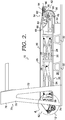
FIG. 2 depicts a side elevation view of the treadmill ofFIG. 1 , in accordance with an aspect hereof; -
FIG. 3 depicts a top perspective view of the area designated by thenumeral 3 inFIG. 1 , showing one example of a dynamic belt-tensioning mechanism, in accordance with an aspect hereof; -
FIG. 4 depicts a side elevation view of the area designated by thenumeral 4 inFIG. 2 , showing a treadmill platform in an elevated position with respect to a treadmill base, in accordance with an aspect hereof; -
FIG. 5 depicts a side elevation view similar toFIG. 4 , but instead shows the treadmill platform in a lowered position with respect to the treadmill base, in accordance with an aspect hereof; -
FIG. 6 depicts a side diagrammatic elevation view of the dynamic belt-tensioning mechanism shown inFIG. 1 with arrows indicating the direction of displacement and rotation of the various parts, in accordance with an aspect hereof; -
FIG. 7 depicts a block diagram of an example process for dynamically tensioning a treadmill belt, in accordance with an aspect hereof; and -
FIG. 8 depicts a block diagram of another example process for dynamically tensioning a treadmill belt, in accordance with an aspect hereof. - The subject matter of this disclosure is described herein to meet statutory requirements. However, this description is not intended to limit the scope hereof. Rather, the claimed subject matter may be embodied in other ways, to include different steps, combinations of steps, features, and/or combinations of features, similar to those described herein, and in conjunction with other present or future technologies. Moreover, although the terms "step" and "block" may be used herein to identify different elements of methods employed, the terms should not be interpreted as implying any particular order among or between various steps or blocks except when the order is explicitly described and required.
-
FIGS. 1-7 describe example apparatuses and mechanisms for dynamically tensioning a belt of a treadmill, as well as methods of using the same. Referring initially toFIG. 1 , atreadmill 10 with a dynamic belt-tensioning mechanism 12 is depicted, in accordance with an aspect hereof. Thetreadmill 10 has abase 14 for supporting thetreadmill 10 on a suitable support surface. Thetreadmill 10 includes aplatform 16 that is supported above thebase 14 and is vertically movable to a number of different vertical positions in response to user interaction on anupper surface 18 of thetreadmill 10. More specifically, any suitable structure can be used to support theplatform 16 above thebase 14 to allow theplatform 16 to move relative to thebase 14 in an up and down manner (e.g., when a user runs on the platform 16). The up and down movement of theplatform 16 therefore accommodates downward force exerted by a user on theupper surface 18 when performing, for instance, a running or walking motion. During a running motion, for example, theplatform 16 may be displaced downward (e.g., towards the base 14) as a user's foot strikes theplatform 16. Still further, as the user's foot is removed during a running motion, theplatform 16 may be moved upward with a rebound force in preparation for the user's other foot striking theupper surface 18. A suitable support structure for supporting theplatform 16 for vertical movement above thebase 14 is thescissor framework 20 depicted inFIG. 1 . Thescissor framework 20 includes afirst scissor arm 22 pivotally mounted to asecond scissor arm 24 at apivot point 26. Thearms platform 16 and thebase 14 to allow theplatform 16 to be positioned at various heights above thebase 14. Thescissor framework 20 is but one example embodiment that allows for vertical movement of theplatform 16 with respect to thebase 14. Other structures and frameworks such as, for instance, linear bearings and/or tracks can provide the same type of vertical motion to theplatform 16. - Referring now to
FIGS. 1-2 , thetreadmill 10 also includes an endless/drive belt 28 that provides a moving surface for a user to engage with during usage of thetreadmill 10. More specifically, thebelt 28 has a fixed circumference and moves over theupper surface 18 of theplatform 16. Thus, as a user, for instance, walks or runs, thebelt 28 is moved beneath the user's feet to allow walking or running at a single location. In addition to moving over theupper surface 18, thebelt 28 also moves under abottom plate 30 of thebase 14. More specifically, referring toFIGS. 1-2 , thebottom plate 30 is supported above a ground surface by a plurality of generallytrapezoidal legs 32 that are also part of thebase 14. Thelegs 32 are positioned along eachedge 34 of theplate 30. Only one of theedges 34 is depicted inFIGS. 1-2 , the other being obscured. Still further, thelegs 32 along eachedge 34 are connected by asupport rib 36 extending downward from alower surface 38 of thebottom plate 30. The provision of asupport rib 36 along each side of thebottom plate 30 defines acavity 40 through which thebelt 28 passes adjacent thelower surface 38 of thebottom plate 30. In this manner, thebelt 28 is able to run in a continuous loop along theupper surface 18 of theplatform 16 and along thelower surface 38 of thebottom plate 30 of thebase 14. - Referring still to
FIGS. 1-2 , abelt drive mechanism 42 is depicted. Thebelt drive mechanism 42 serves to provide the endless motion to thebelt 28 so that the user has a continuous running/walking surface as the user moves across theupper surface 44 of thebelt 28. Thebelt drive mechanism 42 may be used to adjust the speed at which the user runs or walks. Any suitable control system may be used to adjust the speed of thebelt drive mechanism 42 and thus the speed of thebelt 28 shown inFIGS. 1-2 . - The
belt drive mechanism 42 includes adrive roller 46 rotatably mounted to thebase 14 by a pair ofmounting brackets 48 positioned on opposite sides of thebase 14. Only one of themounting brackets 48 is depicted inFIGS. 1-2 , the other being obscured. Themounting brackets 48 extend upwardly from theplate 30 of thebase 14 and each provides a pivot bearing 50 for receiving anaxle 52 of thedrive roller 46. The provision of theaxle 52 rotatably mounted in thepivot bearings 50 allows for the rotating motion of thedrive roller 46. Thedrive roller 46 is coupled to any suitable power source to drive the rotating motion of thedrive roller 46 and thus thebelt 28. The power source is not depicted in the figures, but may be any suitable source such as, for example, an electric motor or a hydraulic motor drivably coupled to thedrive roller 46 by a belt or chain system for example. The power source can also be directly acting on theaxle 52 to accomplish the rotating motion. - Referring still to
FIGS. 1-2 , thetreadmill 10 also includes atransition framework 54 for facilitating a smooth transition of thebelt 28 between the base 14 and theplatform 16, particularly as theplatform 16 is displaced between a number of different vertical positions with respect to the base 14 during operation of thetreadmill 10. Thetransition framework 54 includes asupport structure 56 fixedly mounted to the base 14 adjacent to thebelt drive mechanism 42. The support structure extends along the entirerear edge 58 of thebase 14. Thetransition framework 54 further includes abridge 60 for supporting thebelt 28 as it transitions to the platformupper surface 18 from thedrive roller 46. Thebridge 60 is slidably and pivotally mounted to thesupport structure 56 by a pin andslot arrangement 62 adjacent to arear end 64 of thebridge 60. Thebridge 60 is pivotally mounted to theplatform 16 by apivot arrangement 66 adjacent aforward end 68 of thebridge 60. Thus, as theplatform 16 moves in relation to the base 14 during operation, thebridge 60 pivots and slides with respect to thebase 14 via the pin andslot arrangement 62. Still further, thebridge 60 pivots with respect to theplatform 16 via thepivot arrangement 66 during vertical movement of theplatform 16. In this manner, thebridge 60 changes it's angle relative to theplatform 16 as theplatform 16 becomes vertically displaced and thereby provides a smooth transition support surface for thebelt 28. - Referring still to
FIGS. 1-2 , theplatform 16 further includes anoperator support frame 70 that includes a pair of vertically extendingpillars 72 fixedly mounted to opposite sides of the base 14 adjacent the lower ends 74 of thepillars 72. The operator support frame further includes aconsole 76 mounted between and adjacent to the upper ends 78 of thepillars 72. A pair of bracingarms 80 extend rearwardly from opposite sides of theconsole 76 to provide lateral support and stability for a user engaging with theplatform 16. Theconsole 76 can include various sensors and displays, if desired, to monitor or inform the user. - Referring to
FIGS. 3-6 , the example dynamic belt-tensioningmechanism 12 shown inFIGS. 1-2 is depicted in detail and is disposed adjacent aforward end 82 of thetreadmill 10. Thetensioning mechanism 12 provides increased and/or substantially constant tension to thebelt 28 as theplatform 16 moves up and down in relation to thebase 14. More specifically, thebelt 28 has a fixed circumference. As theplatform 16 moves up and down, the spatial relationship between theplatform 16 and thebase 14 is dynamically changing. Without the belt-tensioningmechanism 12, slack may exist in thebelt 28 as theplatform 16 moves downwardly towards thebase 14. This slack may result in possible disengagement of thebelt 28 from thedrive roller 46. Still further, the slack may result in an unstable running surface on theupper surface 44 of thebelt 28. The belt-tensioningmechanism 12 therefore provides a substantially constant tension in thebelt 28 no matter the relative vertical position of theplatform 16 above the base 14 using thetensioning mechanism 12. - The dynamic belt-tensioning
mechanism 12 includes a pair of support frames 84 mounted adjacent theforward end 82 of thetreadmill 10. The support frames 84 are mounted on theupper surface 85 of theplate 30 of thebase 14. As depicted inFIG. 1 , the support frames 84 are positioned on opposite sides of theplate 30 and extend upwardly from theupper surface 85. Each of the support frames 84 includes a bell crank 86 pivotally mounted thereto by apivot pin 88. Each of the bell cranks 86 includes arear pivot connection 90 connected to afirst end 92 of aplatform linkage 94 by a pivot/ball joint 96. Asecond end 98 of theplatform linkage 94 is pivotally connected to theplatform 16 at apivot point 100 by a pivot/ball joint 102. The pivot/ball joints 96 and 102 may allow for rotation in all directions to minimize friction and binding. Thepivot connection 90 is located at arearward end 104 of thebell crank 86. Thelinkage 94 has alength adjusting turnbuckle 106 that can be used to adjust the length of thelinkage 94. - A
forward end 108 of each bell crank 86 has aforward pivot connection 110 connected to afirst end 112 of a respectivetension roller linkage 114 by apivot pin 116. Asecond end 118 of eachtension roller linkage 114 is pivotally connected to a respectivetension roller mount 120 by thepivot pin 116. The tension roller mounts 120 are positioned on opposite sides of thebase 14 and serve to rotatably mount atension roller 122 by a bearingassembly 124 associated with each of themounts 120. The provision of themounts 120 and the bearingassemblies 124 allow thetension roller 122 to freely rotate. Thetension roller 122 has acylindrical surface 126 that engages with an undersurface 128 of thebelt 28. It is this engagement between thesurface 126 and thebelt surface 128 that provides the tensioning force on thebelt 28 as theplatform 16 moves up and down in relation to thebase 14. Eachtension roller linkage 114 has aload cell transducer 130 that may be used for measuring dynamic belt tension. - Each
tension roller mount 120 is slidably connected to aforward end 132 of arespective support frame 84 by aslide connection 134. Eachslide connection 134 includes a femaleslide groove member 136 that is part of or mounted to thetension roller mount 120 and a maleslide protrusion member 138 that is a part of or mounted to theforward end 132 of thesupport frame 84. With this construction, themounts 120 and thus thetension roller 122 may have a sliding, linear motion capability with respect to the forward ends 132 of the support frames 84. It is this sliding motion that facilitates the dynamic tensioning of thebelt 28. - In addition to the
tension roller 122, anidler roller 140 is also rotatably mounted between the support frames 84 by bearingarrangements 142. Theidler roller 140 also has acylindrical surface 144 that engages thebelt 28 underbelt surface 128. Theidler roller 140 remains positionally fixed, but freely rotatable during operation of thetensioning mechanism 12. Theidler roller 140 serves to support thebelt 28 during operation and assist the dynamic tensioning supplied by the linearly movingtension roller 122. - Referring to
FIG. 6 , during operation of thetreadmill 10, the spatial position of theplatform 16 changes dynamically in a generally vertical direction with respect to the base 14 (e.g., moving towards and away from the base 14). As theplatform 16 moves downwardly, a downward force is exerted on therearward end 104 of thebell crank 86. This downward force results in rotation of the bell crank 86 in a clockwise manner through thelinkage 94. The clockwise rotation of the bell crank 86 results in the generally forward and upward linear movement ofmounts 120 and thus thetension roller 122 through the provision of thetension linkages 114 and theslide connectors 134. The clockwise rotation of the bell crank 86 results in a generally forward and upward force being applied to thetension roller 122 via thelinkages 114. The female slide groove member 136 (shown inFIG. 5 ) slides along themale protrusion 138 to allow the linear movement of thetension roller 122 to occur. The downward movement of theplatform 16 results in less space between theplatform 16 and the base 14 such that slack in the fixedcircumference belt 28 will increase unless addressed by thedynamic tensioning mechanism 12. The generally forward and upward linear movement of thetension roller 122 reduces the slack and assists in keeping a substantially constant tension on thebelt 28. - Still further, as the
platform 16 moves upwardly, the bell crank 86 is rotated in a counterclockwise manner through thelinkage 94. This counterclockwise rotation of the bell crank 86 results in generally reward and downward linear motion of thetension roller 122 through the provision of thelinkages 114, themounts 120, and theslide connections 134. Referring back toFIG. 4 , this upward motion of theplatform 16 is depicted. The upward motion of theplatform 16 results in a greater spatial relationship between theplatform 16 and thebase 14. Therefore, the slack in the fixedcircumference belt 28 may be reduced and therefore may not be as significant. The linear movement of thetension roller 122 adjusts the tension dynamically in response to the movement of theplatform 16. As theplatform 16 moves up and down relative to thebase 14, thetension roller 122 is also dynamically sliding along theslide connections 134 to provide substantially constant, or rather, sustained, tension on thebelt 28. - Referring to
FIG. 7 , a block diagram of anexample method 700 for dynamically tensioning a treadmill belt is provided, in accordance with an aspect hereof. Atblock 146, a treadmill with a base, such as the base 14 shown inFIG. 1 , with a platform, such as theplatform 16 shown inFIG. 1 , mounted thereto to provide vertical movement is provided. Atblock 148, a drive belt, such as thedrive belt 28 shown inFIG. 1 , is powered. Atblock 150, a tensioning roller, such as thetensioning roller 122, is engaged with the drive belt. Atblock 152, the tensioning roller is moved to provide sustained contact tension with the drive belt in response to the vertical movement of the platform. - Referring to
FIG. 8 , a block diagram of anotherexample process 800 for dynamically tensioning a treadmill belt is provided, in accordance with an aspect hereof. Atblock 810, a belt, such as thebelt 28 shown inFIG. 1 , is driven. Atblock 820, a tensioning roller, such as thetensioning roller 122 shown inFIG. 6 , is engaged with the belt. Atblock 830, the tensioning roller is moved, such as by using an assembly of components as shown inFIGS. 5 and6 , to provide substantially constant tension to the belt in response to vertical movement of a treadmill platform, such as theplatform 16 shown inFIG. 1 . - From the foregoing, it will be seen that this invention is one well adapted to attain all the ends and objects hereinabove set forth together with other advantages which are obvious and which are inherent to the structure.
- It will be understood that certain features and sub-combinations are of utility and may be employed without reference to other features and sub-combinations. This is contemplated by and is within the scope of the claims.
- While specific elements and steps are discussed in connection to one another, it is understood that any element and/or steps provided herein is contemplated as being combinable with any other elements and/or steps regardless of explicit provision of the same while still being within the scope provided herein. Since many possible embodiments may be made of the disclosure without departing from the scope thereof, it is to be understood that all matter herein set forth or shown in the accompanying drawings is to be interpreted as illustrative and not in a limiting sense.
-
- 1. A dynamic belt-tensioning apparatus for a treadmill, the apparatus comprising: a base capable of being positioned on a solid surface and having a first end and a second end spaced from the first end; a foot-striking platform movably supported by the base so as to allow vertical movement of the platform during operation of the treadmill; a drive belt having a fixed circumference and positioned above a top portion of the platform so as to provide a moving foot engagement surface during operation of the treadmill; a drive roller rotatably mounted adjacent to the first end of the base that engages the drive belt; and a tensioning roller rotatably mounted to the base and capable of a range of movement to provide substantially constant tension to the drive belt in response to vertical movement of the platform.
The apparatus of clause 1, further comprising a bell crank pivotally mounted adjacent the second end of the base, wherein the bell crank has a pivot point mounted to the base and a first connection point connected to the tensioning roller and a second connection point connected to the platform, and wherein vertical movement of the platform results in movement of the tensioning roller to provide substantially constant tension to the drive belt during operation of the treadmill. - 3. The apparatus of clause 1, further comprising an idler roller rotatably mounted adjacent to the second end of the base that engages the drive belt.
- 4. The apparatus of
clause 2, wherein the first connection point of the bell crank is pivotally attached to the tensioning roller. - 5. The apparatus of
clause 4, wherein the first connection point is attached to the tensioning roller by a linkage. - 6. The apparatus of
clause 2, wherein the second connection point of the bell crank is pivotally attached to the platform. - 7. The apparatus of clause 6, wherein the second connection point is attached to the platform by a linkage.
- 8. The apparatus of
clause 2, wherein the tensioning roller is slidably mounted to the base to provide linear movement of the tensioning roller to deliver substantially constant tension to the belt. - 9. The apparatus of clause 8, wherein the base includes a vertically disposed support frame, and wherein the support frame pivotally mounts the bell crank via the pivot point and slidably mounts the tensioning roller.
- 10. The apparatus of clause 9, wherein the base includes two vertically disposed support frames mounted on opposite sides of the base and two bell cranks that are pivotally mounted respectively to the two vertically disposed support frames.
- 11. The apparatus of
clause 10, wherein a first end of the tensioning roller is rotatably mounted to a first of the support frames and a second end of the tensioning roller is rotatably mounted to a second of the support frames. - 12. The apparatus of clause 11, wherein the first end of the tensioning roller is connected to a first connection point of a first one of the bell cranks and the second end of the tensioning roller is connected to a first connection point of a second one of the bell cranks.
- 13. The apparatus of
clause 12, further comprising an idler roller, wherein a first end of the idler roller is rotatably mounted to the first of the support frames and a second end of the idler roller is rotatably mounted to the second of the support frames. - 14. The apparatus of
clause 2, wherein the bell crank converts a generally vertical force exerted on the platform to a generally horizontal force exerted on the tensioning roller. - 15. A dynamic belt-tensioning apparatus for a treadmill, the apparatus comprising: a base capable of being positioned on a solid surface and having a first end and a second end spaced from the first end and including a first vertically disposed support frame and a second vertically disposed support frame mounted on opposite sides of the base adjacent the second end; a foot-striking platform movably supported by the base so as to allow vertical movement of the platform during operation of the treadmill; a drive belt having a fixed circumference and positioned above a top portion of the platform so as to provide a moving foot engagement surface during operation of the treadmill; a drive roller rotatably mounted adjacent to the first end of the base that engages the drive belt; and a tensioning roller having a first end rotatably and slidably mounted to the first support frame and a second end rotatably and slidably mounted to the second support frame, wherein the tensioning roller is capable of a range of movement to provide substantially constant tension to the drive belt in response to vertical movement of the platform.
- 16. The apparatus of clause 15, further comprising a first bell crank pivotally mounted to the first support frame and a second bell crank pivotally mounted to the second support frame, wherein each bell crank has a pivot point mounted to its respective support frame and a first connection point connected to the tensioning roller and a second connection point connected to the platform, wherein vertical movement of the platform results in movement of the tensioning roller to provide the substantially constant tension to the drive belt during operation of the treadmill.
- 17. The apparatus of clause 15, further comprising an idler roller, wherein a first end of the idler roller is rotatably mounted to the first support frame and a second end of the idler roller is rotatably mounted to the second support frame.
- 18. The apparatus of
clause 16, wherein the first connection point of each bell crank is pivotally attached to the tensioning roller, and wherein the second connection point of each bell crank is pivotally attached to the platform. - 19. The apparatus of
clause 18, wherein the first connection point of each bell crank is attached to the tensioning roller by a linkage, and wherein the second connection point of each bell crank is attached to the platform by a linkage. - 20. A method of tensioning a belt on a treadmill, the treadmill including a base with a platform mounted thereto so that the platform is capable of vertical movement, the method comprising: driving a belt; engaging a tensioning roller with the belt; and moving the tensioning roller to provide substantially constant tension to the belt in response to vertical movement of the platform.
Claims (15)
- A dynamic belt-tensioning apparatus for a treadmill having a base capable of being positioned on a solid surface and having a first end and a second end spaced from the first end, a foot-striking platform movably supported by the base so as to allow vertical movement of the platform during operation of the treadmill, a drive belt having a fixed circumference and positioned above a top portion of the platform so as to provide a moving foot engagement surface during operation of the treadmill, and a drive roller rotatably mounted adjacent to the first end of the base that engages the drive belt, the belt-tensioning apparatus comprising:a tensioning roller adapted to be rotatably mounted to the base and capable of a range of movement to provide substantially constant tension to the drive belt in response to vertical movement of the platform; anda bell crank configured to be pivotally mounted adjacent the second end of the base, wherein the bell crank has a pivot point adapted to be mounted to the base and a first connection point connected to the tensioning roller and a second connection point adapted to be connected to the platform, and wherein vertical movement of the platform results in movement of the tensioning roller to provide substantially constant tension to the drive belt during operation of the treadmill.
- An apparatus according to claim 1, further comprising an idler roller adapted to be rotatably mounted adjacent to the second end of the base that engages the drive belt.
- An apparatus according to claim 1 or 2, wherein the first connection point of the bell crank is pivotally attached to the tensioning roller.
- The apparatus of claim 3, wherein the first connection point is attached to the tensioning roller by a linkage.
- The apparatus of any preceding claim, wherein the second connection point of the bell crank is adapted to be pivotally attached to the platform.
- The apparatus of any preceding claim, wherein the second connection point is adapted to be attached to the platform by a linkage.
- The apparatus of any preceding claim, wherein the tensioning roller is adapted to be slidably mounted to the base to provide linear movement of the tensioning roller to deliver substantially constant tension to the belt.
- The apparatus of any preceding claim, wherein the bell crank converts a generally vertical force exerted on the platform to a generally horizontal force exerted on the tensioning roller.
- A treadmill comprising the apparatus of any preceding claim, further comprising a drive roller rotatably mounted adjacent to the first end of the base that engages the drive belt.
- The treadmill of claim 9, wherein the base includes a vertically disposed support frame, and wherein the support frame pivotally mounts the bell crank via the pivot point and slidably mounts the tensioning roller.
- The apparatus of claim 10, wherein the base includes two vertically disposed support frames mounted on opposite sides of the base and two bell cranks that are pivotally mounted respectively to the two vertically disposed support frames.
- The apparatus of claim 11, wherein a first end of the tensioning roller is rotatably mounted to a first of the support frames and a second end of the tensioning roller is rotatably mounted to a second of the support frames.
- The apparatus of claim 12, wherein the first end of the tensioning roller is connected to a first connection point of a first one of the bell cranks and the second end of the tensioning roller is connected to a first connection point of a second one of the bell cranks.
- The apparatus of any one of claims 11 to 13, when dependent on claim 2 or any claim dependent thereon, wherein a first end of the idler roller is rotatably mounted to the first of the support frames and a second end of the idler roller is rotatably mounted to the second of the support frames.
- A method of tensioning a belt on a treadmill, the treadmill including a base with a platform mounted thereto so that the platform is capable of vertical movement, the method comprising: driving a belt; engaging a tensioning roller with the belt; providing a bell crank pivotally mounted adjacent a second end of the base, wherein the bell crank has a pivot point mounted to the base and a first connection point connected to the tensioning roller and a second connection point connected to the platform, and wherein vertical movement of the platform results in movement of the tensioning roller to provide substantially constant tension to the drive belt during operation of the treadmill.
Applications Claiming Priority (5)
| Application Number | Priority Date | Filing Date | Title |
|---|---|---|---|
| US201762512769P | 2017-05-31 | 2017-05-31 | |
| US201762512770P | 2017-05-31 | 2017-05-31 | |
| US15/991,891 US10857421B2 (en) | 2017-05-31 | 2018-05-29 | Treadmill with dynamic belt tensioning mechanism |
| PCT/US2018/035376 WO2018222861A1 (en) | 2017-05-31 | 2018-05-31 | Treadmill with dynamic belt tensioning mechanism |
| EP18732614.5A EP3630307B1 (en) | 2017-05-31 | 2018-05-31 | Treadmill with dynamic belt tensioning mechanism |
Related Parent Applications (2)
| Application Number | Title | Priority Date | Filing Date |
|---|---|---|---|
| EP18732614.5A Division EP3630307B1 (en) | 2017-05-31 | 2018-05-31 | Treadmill with dynamic belt tensioning mechanism |
| EP18732614.5A Division-Into EP3630307B1 (en) | 2017-05-31 | 2018-05-31 | Treadmill with dynamic belt tensioning mechanism |
Publications (2)
| Publication Number | Publication Date |
|---|---|
| EP3878526A1 true EP3878526A1 (en) | 2021-09-15 |
| EP3878526B1 EP3878526B1 (en) | 2023-10-04 |
Family
ID=62683507
Family Applications (2)
| Application Number | Title | Priority Date | Filing Date |
|---|---|---|---|
| EP21172250.9A Active EP3878526B1 (en) | 2017-05-31 | 2018-05-31 | Treadmill with dynamic belt tensioning mechanism |
| EP18732614.5A Active EP3630307B1 (en) | 2017-05-31 | 2018-05-31 | Treadmill with dynamic belt tensioning mechanism |
Family Applications After (1)
| Application Number | Title | Priority Date | Filing Date |
|---|---|---|---|
| EP18732614.5A Active EP3630307B1 (en) | 2017-05-31 | 2018-05-31 | Treadmill with dynamic belt tensioning mechanism |
Country Status (4)
| Country | Link |
|---|---|
| US (2) | US10857421B2 (en) |
| EP (2) | EP3878526B1 (en) |
| CN (2) | CN110678231B (en) |
| WO (1) | WO2018222861A1 (en) |
Families Citing this family (3)
| Publication number | Priority date | Publication date | Assignee | Title |
|---|---|---|---|---|
| US10918904B2 (en) | 2017-05-31 | 2021-02-16 | Nike, Inc. | Treadmill with vertically displaceable platform |
| US10857421B2 (en) | 2017-05-31 | 2020-12-08 | Nike, Inc. | Treadmill with dynamic belt tensioning mechanism |
| US10898753B2 (en) * | 2018-05-31 | 2021-01-26 | Board Of Regents, The University Of Texas System | Treadmills having adjustable surface stiffness |
Citations (4)
| Publication number | Priority date | Publication date | Assignee | Title |
|---|---|---|---|---|
| US3142193A (en) * | 1961-11-20 | 1964-07-28 | Int Harvester Co | Belt tensioning device |
| US4747810A (en) * | 1979-07-10 | 1988-05-31 | Deere & Company | Belt drive with self-aligning idler |
| US20050209060A1 (en) * | 2004-02-26 | 2005-09-22 | Nautilus, Inc. | Exercise device with treadles |
| US20070281832A1 (en) * | 2006-04-10 | 2007-12-06 | Nerio Alessandri | Gymnastic machine |
Family Cites Families (121)
| Publication number | Priority date | Publication date | Assignee | Title |
|---|---|---|---|---|
| US7241250B1 (en) | 1907-06-27 | 2007-07-10 | Hydroworx | Hydrotherapy and exercise device with integrated lift and treadmill means |
| US2257758A (en) * | 1939-06-15 | 1941-10-07 | American Can Co | Chain tightener device |
| US2506579A (en) * | 1947-05-10 | 1950-05-09 | Goodman Mfg Co | Tensioning device for articulating conveyers |
| US3064797A (en) * | 1960-07-06 | 1962-11-20 | Besel Wilhelm | Automatic tensioning devicf for conveyor belts |
| GB1144818A (en) * | 1966-11-30 | 1969-03-12 | Thompson Brothers Engineers Lt | Improvements in or relating to winches |
| US3479852A (en) * | 1967-04-21 | 1969-11-25 | Archer Products Inc | Rolling apparatus for rounding the edges of strip metal |
| US3731917A (en) | 1971-02-25 | 1973-05-08 | Townsend Engineering Co | Treadmill exercising device |
| US3762229A (en) | 1972-07-10 | 1973-10-02 | Hamilton Brothers Mfg Co | Variable power ratio device |
| US3870297A (en) | 1973-06-18 | 1975-03-11 | Del Mar Eng Lab | Exercise treadmill with inclination controlled chair mounted thereon |
| DK253574A (en) * | 1974-05-09 | 1975-11-10 | Mark & Wedell Ap S | ERGOMETER |
| US3921793A (en) | 1974-07-08 | 1975-11-25 | Goodman Sigmund | Reversible belt tensioning system |
| US4193315A (en) * | 1978-02-06 | 1980-03-18 | The Maytag Company | Belt drive system utilizing an adjustable idler mechanism |
| US4253343A (en) * | 1979-07-10 | 1981-03-03 | Deere & Company | Belt drive system with adjustably gauged tightener means |
| CA1155318A (en) * | 1979-07-10 | 1983-10-18 | Robert D. Black | Belt drive with split idler means |
| US4602779A (en) | 1980-08-05 | 1986-07-29 | Ajax Enterprises Corporation | Exercise treadmill |
| US4566689A (en) | 1980-08-05 | 1986-01-28 | Ajay Enterprises Corporation | Adjustable motor mount arrangement for exercise treadmills |
| CA1135533A (en) * | 1980-11-24 | 1982-11-16 | Derald H. Kraft | Hydraulic belt tensioner construction |
| US4635928A (en) | 1985-04-15 | 1987-01-13 | Ajax Enterprises Corporation | Adjustable speed control arrangement for motorized exercise treadmills |
| US5478027A (en) | 1985-04-24 | 1995-12-26 | Alexander Machinery, Inc. | Web unwinding apparatus and method |
| US4759540A (en) | 1986-10-14 | 1988-07-26 | Industrial Technology Research Institute | Compact structure for a treadmill |
| DE3839391C2 (en) | 1987-11-25 | 1994-06-16 | Stearns Mcgee Inc | Running exercise machine |
| US4849666A (en) | 1987-12-29 | 1989-07-18 | The Charles Stark Draper Laboratory, Inc. | Electromagnetic isolator/actuator system |
| CA2018219C (en) | 1989-06-19 | 1998-03-24 | Richard E. Skowronski | Exercise treadmill |
| US6923746B1 (en) * | 1989-06-19 | 2005-08-02 | Brunswick Corporation | Exercise treadmill |
| US4974831A (en) | 1990-01-10 | 1990-12-04 | Precor Incorporated | Exercise treadmill |
| US5015926A (en) | 1990-02-02 | 1991-05-14 | Casler John A | Electronically controlled force application mechanism for exercise machines |
| US5014979A (en) * | 1990-04-25 | 1991-05-14 | Mccain Manufacturing Corporation | Signature machine |
| US5336145A (en) | 1991-08-30 | 1994-08-09 | Keiser Dennis L | Apparatus having a movable load bearing surface |
| US5302162A (en) | 1992-11-05 | 1994-04-12 | Precor Incorporated | Exercise treadmill with tension-limited belt adjustment |
| US5336146A (en) | 1993-12-15 | 1994-08-09 | Piaget Gary D | Treadmill with dual reciprocating treads |
| US5527245A (en) | 1994-02-03 | 1996-06-18 | Icon Health & Fitness, Inc. | Aerobic and anaerobic exercise machine |
| US5542892A (en) | 1994-08-15 | 1996-08-06 | Unisen, Inc. | Supporting chassis for a treadmill |
| US5529553A (en) | 1995-02-01 | 1996-06-25 | Icon Health & Fitness, Inc. | Treadmill with belt tensioning adjustment |
| CN2245471Y (en) | 1995-10-12 | 1997-01-22 | 国帅工业股份有限公司 | treadmill transmission |
| US5752879A (en) | 1995-12-13 | 1998-05-19 | Berdut; Elberto | Tiltable multi-purpose exercise gym apparatus |
| US5893530A (en) | 1996-08-28 | 1999-04-13 | Alexander Machinery, Inc. | Cushioning apparatus for web roll let-off and method |
| US5993358A (en) * | 1997-03-05 | 1999-11-30 | Lord Corporation | Controllable platform suspension system for treadmill decks and the like and devices therefor |
| US6013011A (en) | 1997-03-31 | 2000-01-11 | Precor Incorporated | Suspension system for exercise apparatus |
| TW339663U (en) | 1997-09-18 | 1998-09-01 | Fu-Yong Qiu | Improved structure of a jogging machine pedal |
| US6394239B1 (en) | 1997-10-29 | 2002-05-28 | Lord Corporation | Controllable medium device and apparatus utilizing same |
| US6042514A (en) | 1998-05-30 | 2000-03-28 | Abelbeck; Kevin G. | Moving surface exercise device |
| US6053848A (en) | 1998-08-24 | 2000-04-25 | Eschenbach; Paul William | Treadmill deck suspension |
| US6821230B2 (en) | 1998-09-25 | 2004-11-23 | Icon Ip, Inc. | Treadmill with adjustable cushioning members |
| US6174267B1 (en) | 1998-09-25 | 2001-01-16 | William T. Dalebout | Treadmill with adjustable cushioning members |
| US7563203B2 (en) | 1998-09-25 | 2009-07-21 | Icon Ip, Inc. | Treadmill with adjustable cushioning members |
| US6202397B1 (en) * | 1999-05-27 | 2001-03-20 | Deere & Company | Draper belt tensioning mechanism for a harvesting platform |
| US6447424B1 (en) | 2000-02-02 | 2002-09-10 | Icon Health & Fitness Inc | System and method for selective adjustment of exercise apparatus |
| US6287240B1 (en) | 1999-08-09 | 2001-09-11 | Michael J. Trabbic | Variable resistance treadmill for simultaneously simulating a rolling and sliding resistance, and a moving inertia |
| US6776740B1 (en) | 1999-09-07 | 2004-08-17 | Brunswick Corporation | Treadmill mechanism |
| CA2426269A1 (en) | 1999-10-22 | 2001-05-03 | Jonathan Mark Burling Showan | Apparatus for simulating a ski slope |
| IT1320937B1 (en) | 2000-01-31 | 2003-12-18 | Technogym Srl | SLIDING CARPET GYMNASTIC MACHINE. |
| US7537549B2 (en) | 2000-02-02 | 2009-05-26 | Icon Ip, Inc. | Incline assembly with cam |
| WO2001056668A1 (en) | 2000-02-03 | 2001-08-09 | American Golf Technologies, Inc. | Portable, weather resistant golf practice device |
| JP3492610B2 (en) * | 2000-09-12 | 2004-02-03 | 株式会社大武ルート工業 | Running machine |
| KR20010083808A (en) | 2001-06-29 | 2001-09-03 | 이상민 | Belt support apparatus for running machine |
| US6878100B2 (en) | 2002-03-21 | 2005-04-12 | The United States Of America As Represented By The Secretary Of The Army | Force sensing treadmill |
| US7455620B2 (en) | 2002-03-21 | 2008-11-25 | The United States Of America As Represented By The Secretary Of The Army | Method for interpreting forces and torques exerted by a left and right foot on a dual-plate treadmill |
| TW529432U (en) | 2002-06-03 | 2003-04-21 | Huang-Dung Jang | Lifting and folding structure of jogging treadmill |
| US7938755B1 (en) | 2002-06-28 | 2011-05-10 | Precor Incorporated | Adjustable exercise device |
| ITBO20020547A1 (en) | 2002-08-27 | 2004-02-28 | Technogym Spa | SUPPORT DEVICE, WITH CUSHIONING, OF A MOBILE BODY OF AN EQUIPMENT FOR GYNNASTIC EXERCISE. |
| US7621850B2 (en) | 2003-02-28 | 2009-11-24 | Nautilus, Inc. | Dual deck exercise device |
| US7553260B2 (en) | 2003-02-28 | 2009-06-30 | Nautilus, Inc. | Exercise device with treadles |
| US6811519B2 (en) | 2003-03-27 | 2004-11-02 | Hai Pin Kuo | Dual treadmill having adjustable resistance |
| US7572206B2 (en) | 2003-06-18 | 2009-08-11 | Scott & Wilkins Enterprises, Llc | Exercise device having position verification feedback |
| DE50306038D1 (en) * | 2003-07-01 | 2007-02-01 | Habasit Ag | Device for stretching and releasing a guided over deflection endless conveyor belt |
| US20050009668A1 (en) | 2003-07-10 | 2005-01-13 | Greg Savettiere | Elliptical/treadmill exercise apparatus |
| US20050164839A1 (en) | 2004-01-09 | 2005-07-28 | Watterson Scott R. | Cushioning treadmill |
| US7507187B2 (en) | 2004-04-06 | 2009-03-24 | Precor Incorporated | Parameter sensing system for an exercise device |
| US20060160669A1 (en) | 2004-12-13 | 2006-07-20 | Lizarralde Inigo I | Linear-response resistance system for exercise equipment |
| US7367926B2 (en) | 2005-08-01 | 2008-05-06 | Fitness Quest Inc. | Exercise treadmill |
| WO2007016555A2 (en) | 2005-08-01 | 2007-02-08 | Fitness Quest Inc. | Exercise treadmill |
| US7163493B1 (en) | 2006-01-19 | 2007-01-16 | Hai Pin Kuo | Treadmill having changeable suspension |
| US20090253559A1 (en) | 2006-03-06 | 2009-10-08 | Joseph Douglas Maresh | Treadmill apparatus |
| JP4113555B2 (en) | 2006-11-29 | 2008-07-09 | 國新産業株式会社 | Running machine belt |
| WO2008099429A1 (en) | 2007-02-14 | 2008-08-21 | Cammax S.A. | Treadmill with endless belt tension adjusting device |
| US20080242511A1 (en) | 2007-03-26 | 2008-10-02 | Brunswick Corporation | User interface methods and apparatus for controlling exercise apparatus |
| US8968160B2 (en) | 2007-06-15 | 2015-03-03 | Cybex International, Inc. | Treadmill belt support assembly |
| US20080312047A1 (en) | 2007-06-18 | 2008-12-18 | Johnson Health Tech Co., Ltd | Treadmill |
| US8172729B2 (en) | 2009-11-16 | 2012-05-08 | Ellis Joseph K | Exercise treadmill for simulating pushing and pulling actions and exercise method therefor |
| US20100160115A1 (en) | 2008-12-19 | 2010-06-24 | Unisen, Inc., Dba Star Trac | User detection for exercise equipment |
| US7874963B2 (en) | 2008-12-29 | 2011-01-25 | Precor Incorporated | Exercise device with adaptive curved track motion |
| PL2419180T3 (en) | 2009-04-15 | 2017-12-29 | Kybun Ag | Belt for a treadmill and treadmill wit a belt |
| US10183191B2 (en) * | 2009-11-02 | 2019-01-22 | Speedfit LLC | Leg-powered treadmill |
| US9005085B2 (en) * | 2009-11-02 | 2015-04-14 | Alex Astilean | Leg-powered treadmill |
| US8206801B2 (en) | 2009-11-06 | 2012-06-26 | Huang-Tung Chang | Buffer board for treadmill |
| TWM382834U (en) | 2009-12-18 | 2010-06-21 | Chun-Liang Wu | Buffer shock-absorbing structure of treadmill |
| US8986176B2 (en) | 2010-02-03 | 2015-03-24 | Lani Renae Arst | Isoped exercise device |
| CA2794479C (en) | 2010-03-26 | 2019-02-12 | Toback, Paul | Exercise apparatus |
| US8597161B2 (en) | 2010-08-10 | 2013-12-03 | Nautilus, Inc. | Motorless treadmill stepper exercise device |
| US8926474B2 (en) | 2011-01-19 | 2015-01-06 | Adam Morris Beal | Endless belt arm exercise device with braking mechanism |
| EP2673056A4 (en) | 2011-02-07 | 2015-09-16 | Gerald M Clum | Shock-absorbing treadmill |
| KR101426831B1 (en) | 2011-09-28 | 2014-08-05 | 이병돈 | Running machine |
| CN202446766U (en) * | 2011-10-25 | 2012-09-26 | 河北路德医疗器械有限公司 | Swing machine core of horse riding body-building machine |
| US9367668B2 (en) | 2012-02-28 | 2016-06-14 | Precor Incorporated | Dynamic fitness equipment user interface adjustment |
| WO2013138375A1 (en) | 2012-03-12 | 2013-09-19 | Core Industries, Llc | Apparatus, system, and method for providing resistance in a dual tread treadmill |
| US9352186B2 (en) | 2012-04-05 | 2016-05-31 | Icon Health & Fitness, Inc. | Treadmill with selectively engageable deck stiffening mechanism |
| US20130267386A1 (en) | 2012-04-06 | 2013-10-10 | Strength Master Fitness Tech Co., Ltd. | Foldable treadmill having lifting mechanism |
| US9233267B2 (en) | 2012-12-20 | 2016-01-12 | Wilkins Ip, Llc | Adjustable rebound device and exercise machine including adjustable rebound device |
| DK2762204T3 (en) | 2013-02-05 | 2016-03-14 | Strength Master Fitness Tech Co Ltd | Tilt and folding device for a treadmill |
| US20140274577A1 (en) | 2013-03-12 | 2014-09-18 | David Beard | Apparatus, system, and method for dual tread treadmill improvements |
| US9943722B2 (en) | 2014-07-25 | 2018-04-17 | Icon Health & Fitness, Inc. | Determining work performed on a treadmill |
| CN111840885B (en) | 2014-10-23 | 2022-04-12 | 阿塞投资有限公司 | Wireless treadmill |
| US9675839B2 (en) | 2014-11-26 | 2017-06-13 | Icon Health & Fitness, Inc. | Treadmill with a tensioning mechanism for a slatted tread belt |
| TWI546103B (en) | 2014-12-30 | 2016-08-21 | Zhong-Fu Zhang | Treadmill of the buffer plate structure |
| CN205633919U (en) * | 2015-03-30 | 2016-10-12 | 乔伊·姆·特拉华公司 | Conveying system's receiving mechanism |
| US9814929B2 (en) | 2015-04-02 | 2017-11-14 | George Moser | Treadmill |
| US20180043207A1 (en) | 2015-04-02 | 2018-02-15 | George Moser | Treadmill |
| CN104801012A (en) | 2015-05-21 | 2015-07-29 | 合肥扁豆智能科技有限公司 | Ultra-thin running machine with foldable running surface |
| US11135472B2 (en) | 2015-06-01 | 2021-10-05 | Johnson Health Tech Co., Ltd. | Exercise apparatus |
| US10857407B2 (en) | 2015-06-01 | 2020-12-08 | Johnson Health Tech Co., Ltd. | Exercise apparatus |
| US12005302B2 (en) | 2015-06-01 | 2024-06-11 | Johnson Health Tech Co., Ltd | Exercise apparatus |
| ITUB20160357A1 (en) | 2016-01-26 | 2017-07-26 | Rx S P A | Treadmill for physical exercise |
| CA2962298C (en) | 2016-03-30 | 2019-08-20 | Clark Walter | Treadmill belts that enhance a user's comfort and stability |
| US10589146B2 (en) | 2016-05-19 | 2020-03-17 | Sara Becker | Exercise treadmill with selectable running surface |
| CN106390369B (en) | 2016-05-27 | 2019-07-02 | 深圳市好家庭实业有限公司 | Carbon fiber shock absorption treadmill and fitness equipment |
| CN106110573B (en) | 2016-07-28 | 2019-05-14 | 京东方科技集团股份有限公司 | Omnidirectional mobile platform and control method thereof, treadmill |
| US10416754B2 (en) | 2017-01-30 | 2019-09-17 | Disney Enterprises, Inc. | Floor system providing omnidirectional movement of a person walking in a virtual reality environment |
| US10857421B2 (en) * | 2017-05-31 | 2020-12-08 | Nike, Inc. | Treadmill with dynamic belt tensioning mechanism |
| US10918904B2 (en) * | 2017-05-31 | 2021-02-16 | Nike, Inc. | Treadmill with vertically displaceable platform |
| US11465012B2 (en) | 2017-06-16 | 2022-10-11 | Core Health & Fitness, Llc | Apparatus, system, and method for a flexible treadmill deck |
| US20220062698A1 (en) | 2020-09-01 | 2022-03-03 | Yu-Lun TSAI | Treadmill Walking Board Assembly Having Functions of Flow Guidance, Air Exhaust and Heat Dissipation |
-
2018
- 2018-05-29 US US15/991,891 patent/US10857421B2/en active Active
- 2018-05-31 CN CN201880035703.4A patent/CN110678231B/en active Active
- 2018-05-31 EP EP21172250.9A patent/EP3878526B1/en active Active
- 2018-05-31 EP EP18732614.5A patent/EP3630307B1/en active Active
- 2018-05-31 WO PCT/US2018/035376 patent/WO2018222861A1/en not_active Ceased
- 2018-05-31 CN CN202111030652.6A patent/CN113786584B/en active Active
-
2020
- 2020-11-24 US US17/103,574 patent/US11565147B2/en active Active
Patent Citations (4)
| Publication number | Priority date | Publication date | Assignee | Title |
|---|---|---|---|---|
| US3142193A (en) * | 1961-11-20 | 1964-07-28 | Int Harvester Co | Belt tensioning device |
| US4747810A (en) * | 1979-07-10 | 1988-05-31 | Deere & Company | Belt drive with self-aligning idler |
| US20050209060A1 (en) * | 2004-02-26 | 2005-09-22 | Nautilus, Inc. | Exercise device with treadles |
| US20070281832A1 (en) * | 2006-04-10 | 2007-12-06 | Nerio Alessandri | Gymnastic machine |
Also Published As
| Publication number | Publication date |
|---|---|
| WO2018222861A1 (en) | 2018-12-06 |
| US20180345069A1 (en) | 2018-12-06 |
| EP3630307A1 (en) | 2020-04-08 |
| US20210069544A1 (en) | 2021-03-11 |
| EP3878526B1 (en) | 2023-10-04 |
| EP3630307B1 (en) | 2021-06-30 |
| CN110678231A (en) | 2020-01-10 |
| US11565147B2 (en) | 2023-01-31 |
| CN110678231B (en) | 2021-09-10 |
| CN113786584B (en) | 2023-05-26 |
| US10857421B2 (en) | 2020-12-08 |
| CN113786584A (en) | 2021-12-14 |
Similar Documents
| Publication | Publication Date | Title |
|---|---|---|
| US11565147B2 (en) | Treadmill with dynamic belt tensioning mechanism | |
| US7922625B2 (en) | Adaptive motion exercise device with oscillating track | |
| TWI680782B (en) | Offsetting treadmill deck weight during operation | |
| CN101822890B (en) | Adaptive motion exercise device with plural crank assemblies | |
| US7758472B2 (en) | Exercise device ramp roller retainer | |
| US8308619B1 (en) | Leg-powered treadmill | |
| CN102156054B (en) | Walking capacity tester of foot robot | |
| US11666799B2 (en) | Treadmill with vertically displaceable platform | |
| TW201524550A (en) | Exercise device providing elliptical exercising paths | |
| US20190224522A1 (en) | Lateral Tilting Treadmill Systems | |
| KR101371607B1 (en) | Deck support structure of treadmill | |
| US10213644B2 (en) | Elliptical trainer | |
| US20040152564A1 (en) | Treadmill having treadmill frame adjusting device | |
| KR101550814B1 (en) | Step type bipedal locomotion | |
| CN202188963U (en) | Device for testing walking capacity of foot robot | |
| CN223225158U (en) | Crawler-type self-moving tail machine with corrective function | |
| KR20010104855A (en) | A running machine | |
| KR20120051825A (en) | Treadmill | |
| KR101398491B1 (en) | A traveling shoes assembly | |
| CN121757300A (en) | Chassis structure and humanoid robot |
Legal Events
| Date | Code | Title | Description |
|---|---|---|---|
| PUAI | Public reference made under article 153(3) epc to a published international application that has entered the european phase |
Free format text: ORIGINAL CODE: 0009012 |
|
| STAA | Information on the status of an ep patent application or granted ep patent |
Free format text: STATUS: THE APPLICATION HAS BEEN PUBLISHED |
|
| AC | Divisional application: reference to earlier application |
Ref document number: 3630307 Country of ref document: EP Kind code of ref document: P |
|
| AK | Designated contracting states |
Kind code of ref document: A1 Designated state(s): AL AT BE BG CH CY CZ DE DK EE ES FI FR GB GR HR HU IE IS IT LI LT LU LV MC MK MT NL NO PL PT RO RS SE SI SK SM TR |
|
| STAA | Information on the status of an ep patent application or granted ep patent |
Free format text: STATUS: REQUEST FOR EXAMINATION WAS MADE |
|
| 17P | Request for examination filed |
Effective date: 20220315 |
|
| RBV | Designated contracting states (corrected) |
Designated state(s): AL AT BE BG CH CY CZ DE DK EE ES FI FR GB GR HR HU IE IS IT LI LT LU LV MC MK MT NL NO PL PT RO RS SE SI SK SM TR |
|
| P01 | Opt-out of the competence of the unified patent court (upc) registered |
Effective date: 20230515 |
|
| GRAP | Despatch of communication of intention to grant a patent |
Free format text: ORIGINAL CODE: EPIDOSNIGR1 |
|
| STAA | Information on the status of an ep patent application or granted ep patent |
Free format text: STATUS: GRANT OF PATENT IS INTENDED |
|
| INTG | Intention to grant announced |
Effective date: 20230706 |
|
| GRAS | Grant fee paid |
Free format text: ORIGINAL CODE: EPIDOSNIGR3 |
|
| GRAA | (expected) grant |
Free format text: ORIGINAL CODE: 0009210 |
|
| STAA | Information on the status of an ep patent application or granted ep patent |
Free format text: STATUS: THE PATENT HAS BEEN GRANTED |
|
| AC | Divisional application: reference to earlier application |
Ref document number: 3630307 Country of ref document: EP Kind code of ref document: P |
|
| AK | Designated contracting states |
Kind code of ref document: B1 Designated state(s): AL AT BE BG CH CY CZ DE DK EE ES FI FR GB GR HR HU IE IS IT LI LT LU LV MC MK MT NL NO PL PT RO RS SE SI SK SM TR |
|
| REG | Reference to a national code |
Ref country code: GB Ref legal event code: FG4D |
|
| REG | Reference to a national code |
Ref country code: CH Ref legal event code: EP |
|
| REG | Reference to a national code |
Ref country code: DE Ref legal event code: R096 Ref document number: 602018059016 Country of ref document: DE |
|
| REG | Reference to a national code |
Ref country code: IE Ref legal event code: FG4D |
|
| REG | Reference to a national code |
Ref country code: LT Ref legal event code: MG9D |
|
| REG | Reference to a national code |
Ref country code: NL Ref legal event code: MP Effective date: 20231004 |
|
| REG | Reference to a national code |
Ref country code: AT Ref legal event code: MK05 Ref document number: 1617124 Country of ref document: AT Kind code of ref document: T Effective date: 20231004 |
|
| PG25 | Lapsed in a contracting state [announced via postgrant information from national office to epo] |
Ref country code: NL Free format text: LAPSE BECAUSE OF FAILURE TO SUBMIT A TRANSLATION OF THE DESCRIPTION OR TO PAY THE FEE WITHIN THE PRESCRIBED TIME-LIMIT Effective date: 20231004 |
|
| PG25 | Lapsed in a contracting state [announced via postgrant information from national office to epo] |
Ref country code: GR Free format text: LAPSE BECAUSE OF FAILURE TO SUBMIT A TRANSLATION OF THE DESCRIPTION OR TO PAY THE FEE WITHIN THE PRESCRIBED TIME-LIMIT Effective date: 20240105 |
|
| PG25 | Lapsed in a contracting state [announced via postgrant information from national office to epo] |
Ref country code: IS Free format text: LAPSE BECAUSE OF FAILURE TO SUBMIT A TRANSLATION OF THE DESCRIPTION OR TO PAY THE FEE WITHIN THE PRESCRIBED TIME-LIMIT Effective date: 20240204 |
|
| PG25 | Lapsed in a contracting state [announced via postgrant information from national office to epo] |
Ref country code: LT Free format text: LAPSE BECAUSE OF FAILURE TO SUBMIT A TRANSLATION OF THE DESCRIPTION OR TO PAY THE FEE WITHIN THE PRESCRIBED TIME-LIMIT Effective date: 20231004 |
|
| PG25 | Lapsed in a contracting state [announced via postgrant information from national office to epo] |
Ref country code: AT Free format text: LAPSE BECAUSE OF FAILURE TO SUBMIT A TRANSLATION OF THE DESCRIPTION OR TO PAY THE FEE WITHIN THE PRESCRIBED TIME-LIMIT Effective date: 20231004 |
|
| PG25 | Lapsed in a contracting state [announced via postgrant information from national office to epo] |
Ref country code: ES Free format text: LAPSE BECAUSE OF FAILURE TO SUBMIT A TRANSLATION OF THE DESCRIPTION OR TO PAY THE FEE WITHIN THE PRESCRIBED TIME-LIMIT Effective date: 20231004 |
|
| PG25 | Lapsed in a contracting state [announced via postgrant information from national office to epo] |
Ref country code: LT Free format text: LAPSE BECAUSE OF FAILURE TO SUBMIT A TRANSLATION OF THE DESCRIPTION OR TO PAY THE FEE WITHIN THE PRESCRIBED TIME-LIMIT Effective date: 20231004 Ref country code: IS Free format text: LAPSE BECAUSE OF FAILURE TO SUBMIT A TRANSLATION OF THE DESCRIPTION OR TO PAY THE FEE WITHIN THE PRESCRIBED TIME-LIMIT Effective date: 20240204 Ref country code: GR Free format text: LAPSE BECAUSE OF FAILURE TO SUBMIT A TRANSLATION OF THE DESCRIPTION OR TO PAY THE FEE WITHIN THE PRESCRIBED TIME-LIMIT Effective date: 20240105 Ref country code: ES Free format text: LAPSE BECAUSE OF FAILURE TO SUBMIT A TRANSLATION OF THE DESCRIPTION OR TO PAY THE FEE WITHIN THE PRESCRIBED TIME-LIMIT Effective date: 20231004 Ref country code: BG Free format text: LAPSE BECAUSE OF FAILURE TO SUBMIT A TRANSLATION OF THE DESCRIPTION OR TO PAY THE FEE WITHIN THE PRESCRIBED TIME-LIMIT Effective date: 20240104 Ref country code: AT Free format text: LAPSE BECAUSE OF FAILURE TO SUBMIT A TRANSLATION OF THE DESCRIPTION OR TO PAY THE FEE WITHIN THE PRESCRIBED TIME-LIMIT Effective date: 20231004 Ref country code: PT Free format text: LAPSE BECAUSE OF FAILURE TO SUBMIT A TRANSLATION OF THE DESCRIPTION OR TO PAY THE FEE WITHIN THE PRESCRIBED TIME-LIMIT Effective date: 20240205 |
|
| PG25 | Lapsed in a contracting state [announced via postgrant information from national office to epo] |
Ref country code: SE Free format text: LAPSE BECAUSE OF FAILURE TO SUBMIT A TRANSLATION OF THE DESCRIPTION OR TO PAY THE FEE WITHIN THE PRESCRIBED TIME-LIMIT Effective date: 20231004 Ref country code: RS Free format text: LAPSE BECAUSE OF FAILURE TO SUBMIT A TRANSLATION OF THE DESCRIPTION OR TO PAY THE FEE WITHIN THE PRESCRIBED TIME-LIMIT Effective date: 20231004 Ref country code: PL Free format text: LAPSE BECAUSE OF FAILURE TO SUBMIT A TRANSLATION OF THE DESCRIPTION OR TO PAY THE FEE WITHIN THE PRESCRIBED TIME-LIMIT Effective date: 20231004 Ref country code: NO Free format text: LAPSE BECAUSE OF FAILURE TO SUBMIT A TRANSLATION OF THE DESCRIPTION OR TO PAY THE FEE WITHIN THE PRESCRIBED TIME-LIMIT Effective date: 20240104 Ref country code: LV Free format text: LAPSE BECAUSE OF FAILURE TO SUBMIT A TRANSLATION OF THE DESCRIPTION OR TO PAY THE FEE WITHIN THE PRESCRIBED TIME-LIMIT Effective date: 20231004 Ref country code: HR Free format text: LAPSE BECAUSE OF FAILURE TO SUBMIT A TRANSLATION OF THE DESCRIPTION OR TO PAY THE FEE WITHIN THE PRESCRIBED TIME-LIMIT Effective date: 20231004 |
|
| REG | Reference to a national code |
Ref country code: DE Ref legal event code: R097 Ref document number: 602018059016 Country of ref document: DE |
|
| PG25 | Lapsed in a contracting state [announced via postgrant information from national office to epo] |
Ref country code: DK Free format text: LAPSE BECAUSE OF FAILURE TO SUBMIT A TRANSLATION OF THE DESCRIPTION OR TO PAY THE FEE WITHIN THE PRESCRIBED TIME-LIMIT Effective date: 20231004 |
|
| PG25 | Lapsed in a contracting state [announced via postgrant information from national office to epo] |
Ref country code: CZ Free format text: LAPSE BECAUSE OF FAILURE TO SUBMIT A TRANSLATION OF THE DESCRIPTION OR TO PAY THE FEE WITHIN THE PRESCRIBED TIME-LIMIT Effective date: 20231004 |
|
| PG25 | Lapsed in a contracting state [announced via postgrant information from national office to epo] |
Ref country code: SK Free format text: LAPSE BECAUSE OF FAILURE TO SUBMIT A TRANSLATION OF THE DESCRIPTION OR TO PAY THE FEE WITHIN THE PRESCRIBED TIME-LIMIT Effective date: 20231004 |
|
| PG25 | Lapsed in a contracting state [announced via postgrant information from national office to epo] |
Ref country code: SM Free format text: LAPSE BECAUSE OF FAILURE TO SUBMIT A TRANSLATION OF THE DESCRIPTION OR TO PAY THE FEE WITHIN THE PRESCRIBED TIME-LIMIT Effective date: 20231004 Ref country code: SK Free format text: LAPSE BECAUSE OF FAILURE TO SUBMIT A TRANSLATION OF THE DESCRIPTION OR TO PAY THE FEE WITHIN THE PRESCRIBED TIME-LIMIT Effective date: 20231004 Ref country code: RO Free format text: LAPSE BECAUSE OF FAILURE TO SUBMIT A TRANSLATION OF THE DESCRIPTION OR TO PAY THE FEE WITHIN THE PRESCRIBED TIME-LIMIT Effective date: 20231004 Ref country code: IT Free format text: LAPSE BECAUSE OF FAILURE TO SUBMIT A TRANSLATION OF THE DESCRIPTION OR TO PAY THE FEE WITHIN THE PRESCRIBED TIME-LIMIT Effective date: 20231004 Ref country code: EE Free format text: LAPSE BECAUSE OF FAILURE TO SUBMIT A TRANSLATION OF THE DESCRIPTION OR TO PAY THE FEE WITHIN THE PRESCRIBED TIME-LIMIT Effective date: 20231004 Ref country code: DK Free format text: LAPSE BECAUSE OF FAILURE TO SUBMIT A TRANSLATION OF THE DESCRIPTION OR TO PAY THE FEE WITHIN THE PRESCRIBED TIME-LIMIT Effective date: 20231004 Ref country code: CZ Free format text: LAPSE BECAUSE OF FAILURE TO SUBMIT A TRANSLATION OF THE DESCRIPTION OR TO PAY THE FEE WITHIN THE PRESCRIBED TIME-LIMIT Effective date: 20231004 |
|
| PLBE | No opposition filed within time limit |
Free format text: ORIGINAL CODE: 0009261 |
|
| STAA | Information on the status of an ep patent application or granted ep patent |
Free format text: STATUS: NO OPPOSITION FILED WITHIN TIME LIMIT |
|
| 26N | No opposition filed |
Effective date: 20240705 |
|
| PG25 | Lapsed in a contracting state [announced via postgrant information from national office to epo] |
Ref country code: SI Free format text: LAPSE BECAUSE OF FAILURE TO SUBMIT A TRANSLATION OF THE DESCRIPTION OR TO PAY THE FEE WITHIN THE PRESCRIBED TIME-LIMIT Effective date: 20231004 |
|
| PG25 | Lapsed in a contracting state [announced via postgrant information from national office to epo] |
Ref country code: SI Free format text: LAPSE BECAUSE OF FAILURE TO SUBMIT A TRANSLATION OF THE DESCRIPTION OR TO PAY THE FEE WITHIN THE PRESCRIBED TIME-LIMIT Effective date: 20231004 |
|
| REG | Reference to a national code |
Ref country code: CH Ref legal event code: PL |
|
| PG25 | Lapsed in a contracting state [announced via postgrant information from national office to epo] |
Ref country code: MC Free format text: LAPSE BECAUSE OF FAILURE TO SUBMIT A TRANSLATION OF THE DESCRIPTION OR TO PAY THE FEE WITHIN THE PRESCRIBED TIME-LIMIT Effective date: 20231004 |
|
| PG25 | Lapsed in a contracting state [announced via postgrant information from national office to epo] |
Ref country code: LU Free format text: LAPSE BECAUSE OF NON-PAYMENT OF DUE FEES Effective date: 20240531 |
|
| PG25 | Lapsed in a contracting state [announced via postgrant information from national office to epo] |
Ref country code: MC Free format text: LAPSE BECAUSE OF FAILURE TO SUBMIT A TRANSLATION OF THE DESCRIPTION OR TO PAY THE FEE WITHIN THE PRESCRIBED TIME-LIMIT Effective date: 20231004 Ref country code: LU Free format text: LAPSE BECAUSE OF NON-PAYMENT OF DUE FEES Effective date: 20240531 Ref country code: CH Free format text: LAPSE BECAUSE OF NON-PAYMENT OF DUE FEES Effective date: 20240531 |
|
| REG | Reference to a national code |
Ref country code: BE Ref legal event code: MM Effective date: 20240531 |
|
| PG25 | Lapsed in a contracting state [announced via postgrant information from national office to epo] |
Ref country code: IE Free format text: LAPSE BECAUSE OF NON-PAYMENT OF DUE FEES Effective date: 20240531 |
|
| PG25 | Lapsed in a contracting state [announced via postgrant information from national office to epo] |
Ref country code: BE Free format text: LAPSE BECAUSE OF NON-PAYMENT OF DUE FEES Effective date: 20240531 |
|
| PGFP | Annual fee paid to national office [announced via postgrant information from national office to epo] |
Ref country code: DE Payment date: 20250402 Year of fee payment: 8 |
|
| PGFP | Annual fee paid to national office [announced via postgrant information from national office to epo] |
Ref country code: GB Payment date: 20250401 Year of fee payment: 8 |
|
| PGFP | Annual fee paid to national office [announced via postgrant information from national office to epo] |
Ref country code: FR Payment date: 20250401 Year of fee payment: 8 |
|
| PG25 | Lapsed in a contracting state [announced via postgrant information from national office to epo] |
Ref country code: CY Free format text: LAPSE BECAUSE OF FAILURE TO SUBMIT A TRANSLATION OF THE DESCRIPTION OR TO PAY THE FEE WITHIN THE PRESCRIBED TIME-LIMIT; INVALID AB INITIO Effective date: 20180531 |
|
| PG25 | Lapsed in a contracting state [announced via postgrant information from national office to epo] |
Ref country code: FI Free format text: LAPSE BECAUSE OF FAILURE TO SUBMIT A TRANSLATION OF THE DESCRIPTION OR TO PAY THE FEE WITHIN THE PRESCRIBED TIME-LIMIT Effective date: 20231004 |
|
| PG25 | Lapsed in a contracting state [announced via postgrant information from national office to epo] |
Ref country code: HU Free format text: LAPSE BECAUSE OF FAILURE TO SUBMIT A TRANSLATION OF THE DESCRIPTION OR TO PAY THE FEE WITHIN THE PRESCRIBED TIME-LIMIT; INVALID AB INITIO Effective date: 20180531 |
|
| PG25 | Lapsed in a contracting state [announced via postgrant information from national office to epo] |
Ref country code: TR Free format text: LAPSE BECAUSE OF FAILURE TO SUBMIT A TRANSLATION OF THE DESCRIPTION OR TO PAY THE FEE WITHIN THE PRESCRIBED TIME-LIMIT Effective date: 20231004 |