EP3878362A1 - Bed exit prediction based on patient behavior patterns - Google Patents
Bed exit prediction based on patient behavior patterns Download PDFInfo
- Publication number
- EP3878362A1 EP3878362A1 EP21161026.6A EP21161026A EP3878362A1 EP 3878362 A1 EP3878362 A1 EP 3878362A1 EP 21161026 A EP21161026 A EP 21161026A EP 3878362 A1 EP3878362 A1 EP 3878362A1
- Authority
- EP
- European Patent Office
- Prior art keywords
- patient
- data related
- support apparatus
- behavior
- automatically
- Prior art date
- Legal status (The legal status is an assumption and is not a legal conclusion. Google has not performed a legal analysis and makes no representation as to the accuracy of the status listed.)
- Pending
Links
Images


Classifications
-
- G—PHYSICS
- G16—INFORMATION AND COMMUNICATION TECHNOLOGY [ICT] SPECIALLY ADAPTED FOR SPECIFIC APPLICATION FIELDS
- G16H—HEALTHCARE INFORMATICS, i.e. INFORMATION AND COMMUNICATION TECHNOLOGY [ICT] SPECIALLY ADAPTED FOR THE HANDLING OR PROCESSING OF MEDICAL OR HEALTHCARE DATA
- G16H40/00—ICT specially adapted for the management or administration of healthcare resources or facilities; ICT specially adapted for the management or operation of medical equipment or devices
- G16H40/60—ICT specially adapted for the management or administration of healthcare resources or facilities; ICT specially adapted for the management or operation of medical equipment or devices for the operation of medical equipment or devices
- G16H40/63—ICT specially adapted for the management or administration of healthcare resources or facilities; ICT specially adapted for the management or operation of medical equipment or devices for the operation of medical equipment or devices for local operation
-
- G—PHYSICS
- G16—INFORMATION AND COMMUNICATION TECHNOLOGY [ICT] SPECIALLY ADAPTED FOR SPECIFIC APPLICATION FIELDS
- G16H—HEALTHCARE INFORMATICS, i.e. INFORMATION AND COMMUNICATION TECHNOLOGY [ICT] SPECIALLY ADAPTED FOR THE HANDLING OR PROCESSING OF MEDICAL OR HEALTHCARE DATA
- G16H40/00—ICT specially adapted for the management or administration of healthcare resources or facilities; ICT specially adapted for the management or operation of medical equipment or devices
- G16H40/20—ICT specially adapted for the management or administration of healthcare resources or facilities; ICT specially adapted for the management or operation of medical equipment or devices for the management or administration of healthcare resources or facilities, e.g. managing hospital staff or surgery rooms
-
- A—HUMAN NECESSITIES
- A61—MEDICAL OR VETERINARY SCIENCE; HYGIENE
- A61B—DIAGNOSIS; SURGERY; IDENTIFICATION
- A61B5/00—Measuring for diagnostic purposes; Identification of persons
- A61B5/0002—Remote monitoring of patients using telemetry, e.g. transmission of vital signals via a communication network
- A61B5/0015—Remote monitoring of patients using telemetry, e.g. transmission of vital signals via a communication network characterised by features of the telemetry system
- A61B5/002—Monitoring the patient using a local or closed circuit, e.g. in a room or building
-
- A—HUMAN NECESSITIES
- A61—MEDICAL OR VETERINARY SCIENCE; HYGIENE
- A61B—DIAGNOSIS; SURGERY; IDENTIFICATION
- A61B5/00—Measuring for diagnostic purposes; Identification of persons
- A61B5/103—Measuring devices for testing the shape, pattern, colour, size or movement of the body or parts thereof, for diagnostic purposes
- A61B5/11—Measuring movement of the entire body or parts thereof, e.g. head or hand tremor or mobility of a limb
- A61B5/1113—Local tracking of patients, e.g. in a hospital or private home
- A61B5/1115—Monitoring leaving of a patient support, e.g. a bed or a wheelchair
-
- A—HUMAN NECESSITIES
- A61—MEDICAL OR VETERINARY SCIENCE; HYGIENE
- A61B—DIAGNOSIS; SURGERY; IDENTIFICATION
- A61B5/00—Measuring for diagnostic purposes; Identification of persons
- A61B5/103—Measuring devices for testing the shape, pattern, colour, size or movement of the body or parts thereof, for diagnostic purposes
- A61B5/11—Measuring movement of the entire body or parts thereof, e.g. head or hand tremor or mobility of a limb
- A61B5/1126—Measuring movement of the entire body or parts thereof, e.g. head or hand tremor or mobility of a limb using a particular sensing technique
- A61B5/1127—Measuring movement of the entire body or parts thereof, e.g. head or hand tremor or mobility of a limb using a particular sensing technique using markers
-
- A—HUMAN NECESSITIES
- A61—MEDICAL OR VETERINARY SCIENCE; HYGIENE
- A61B—DIAGNOSIS; SURGERY; IDENTIFICATION
- A61B5/00—Measuring for diagnostic purposes; Identification of persons
- A61B5/103—Measuring devices for testing the shape, pattern, colour, size or movement of the body or parts thereof, for diagnostic purposes
- A61B5/11—Measuring movement of the entire body or parts thereof, e.g. head or hand tremor or mobility of a limb
- A61B5/1126—Measuring movement of the entire body or parts thereof, e.g. head or hand tremor or mobility of a limb using a particular sensing technique
- A61B5/1128—Measuring movement of the entire body or parts thereof, e.g. head or hand tremor or mobility of a limb using a particular sensing technique using image analysis
-
- A—HUMAN NECESSITIES
- A61—MEDICAL OR VETERINARY SCIENCE; HYGIENE
- A61B—DIAGNOSIS; SURGERY; IDENTIFICATION
- A61B5/00—Measuring for diagnostic purposes; Identification of persons
- A61B5/72—Signal processing specially adapted for physiological signals or for diagnostic purposes
- A61B5/7235—Details of waveform analysis
- A61B5/7264—Classification of physiological signals or data, e.g. using neural networks, statistical classifiers, expert systems or fuzzy systems
- A61B5/7267—Classification of physiological signals or data, e.g. using neural networks, statistical classifiers, expert systems or fuzzy systems involving training the classification device
-
- A—HUMAN NECESSITIES
- A61—MEDICAL OR VETERINARY SCIENCE; HYGIENE
- A61B—DIAGNOSIS; SURGERY; IDENTIFICATION
- A61B5/00—Measuring for diagnostic purposes; Identification of persons
- A61B5/72—Signal processing specially adapted for physiological signals or for diagnostic purposes
- A61B5/7271—Specific aspects of physiological measurement analysis
- A61B5/7275—Determining trends in physiological measurement data; Predicting development of a medical condition based on physiological measurements, e.g. determining a risk factor
-
- A—HUMAN NECESSITIES
- A61—MEDICAL OR VETERINARY SCIENCE; HYGIENE
- A61B—DIAGNOSIS; SURGERY; IDENTIFICATION
- A61B5/00—Measuring for diagnostic purposes; Identification of persons
- A61B5/74—Details of notification to user or communication with user or patient; User input means
-
- G—PHYSICS
- G06—COMPUTING OR CALCULATING; COUNTING
- G06N—COMPUTING ARRANGEMENTS BASED ON SPECIFIC COMPUTATIONAL MODELS
- G06N20/00—Machine learning
-
- G—PHYSICS
- G16—INFORMATION AND COMMUNICATION TECHNOLOGY [ICT] SPECIALLY ADAPTED FOR SPECIFIC APPLICATION FIELDS
- G16H—HEALTHCARE INFORMATICS, i.e. INFORMATION AND COMMUNICATION TECHNOLOGY [ICT] SPECIALLY ADAPTED FOR THE HANDLING OR PROCESSING OF MEDICAL OR HEALTHCARE DATA
- G16H50/00—ICT specially adapted for medical diagnosis, medical simulation or medical data mining; ICT specially adapted for detecting, monitoring or modelling epidemics or pandemics
- G16H50/20—ICT specially adapted for medical diagnosis, medical simulation or medical data mining; ICT specially adapted for detecting, monitoring or modelling epidemics or pandemics for computer-aided diagnosis, e.g. based on medical expert systems
-
- G—PHYSICS
- G16—INFORMATION AND COMMUNICATION TECHNOLOGY [ICT] SPECIALLY ADAPTED FOR SPECIFIC APPLICATION FIELDS
- G16H—HEALTHCARE INFORMATICS, i.e. INFORMATION AND COMMUNICATION TECHNOLOGY [ICT] SPECIALLY ADAPTED FOR THE HANDLING OR PROCESSING OF MEDICAL OR HEALTHCARE DATA
- G16H50/00—ICT specially adapted for medical diagnosis, medical simulation or medical data mining; ICT specially adapted for detecting, monitoring or modelling epidemics or pandemics
- G16H50/30—ICT specially adapted for medical diagnosis, medical simulation or medical data mining; ICT specially adapted for detecting, monitoring or modelling epidemics or pandemics for calculating health indices; for individual health risk assessment
-
- A—HUMAN NECESSITIES
- A61—MEDICAL OR VETERINARY SCIENCE; HYGIENE
- A61B—DIAGNOSIS; SURGERY; IDENTIFICATION
- A61B5/00—Measuring for diagnostic purposes; Identification of persons
- A61B5/103—Measuring devices for testing the shape, pattern, colour, size or movement of the body or parts thereof, for diagnostic purposes
- A61B5/11—Measuring movement of the entire body or parts thereof, e.g. head or hand tremor or mobility of a limb
- A61B5/1116—Determining posture transitions
- A61B5/1117—Fall detection
Definitions
- the present disclosure is related to a patient support apparatus that can predict patient bed exits. More specifically, the present disclosure is related to a patient support apparatus that includes a control system that can predict patient bed exit, displays information related to the exit on a user interface, and alerts the caregiver.
- the mobility of a person supported on a patient support apparatus is of interest to caregivers in assessing the risk of the patient making unassisted bed exits.
- the patient When making an unassisted bed exit, the patient may be at risk for falling and subsequent injury.
- Many devices, including bed exit alarms, real-time locating systems, and cameras may be used to monitor when a patient exits the bed.
- the present disclosure includes one or more of the following features alone or in any combination.
- a method for inferring a patient's future behavior may include acquiring data related to patient bed exits.
- the method may also include analyzing the data related to patient bed exits to detect patterns in patient bed exit behavior.
- the method may also include building a customized schedule of patient bed exit behavior to predicts future patient bed exits.
- the method may also include notifying a caregiver when a future patient bed exit is to occur.
- the method may include acquiring data related to patient bed exits includes acquiring data from a sensor in a patient support apparatus.
- the method may also include acquiring data related to patient bed exits includes acquiring data from a real time locating system.
- the method may also include acquiring data related to patient bed exits includes acquiring data from a camera in a patient room.
- the method may also include acquiring data related to patient bed exits includes acquiring data related to the patient's medical schedule.
- the method may also include acquiring data related to patient bed exits includes acquiring data related to the patient's mealtime schedule.
- the method may also include acquiring data related to patient bed exits includes acquiring data related to the patient's visiting hours schedule.
- the method includes combining historical data from similar patients to the data related to patient bed exits to determine a model that predicts future patient bed exits.
- the method may also include notifying a caregiver when a future patient bed exit is to occur further comprises notifying a caregiver a predetermined time before the future patient bed exit is to occur.
- the method may also include comparing a patient's current behavior to a patient's predicted behavior.
- the method may also include updating the customized schedule based on differences between a patient's current behavior and a patient's predicted behavior.
- the method may also include notifying a caregiver when a future patient bed exit is to occur further comprises notifying the caregiver before the patient wakes up.
- the method may also include notifying a caregiver when a future patient bed exit is to occur further comprises notifying the caregiver before the patient uses the restroom.
- a system for inferring a patient's future behavior may include a patient support apparatus.
- a data acquisition system may track data related to patient bed exits from the patient support apparatus.
- a controller may be in communication with the patient support apparatus.
- the controller may include a processor and a non-transitory memory device.
- the memory device may include instructions that, when executed by the processor, acquire data related to patient bed exits, analyze the data related to patient bed exits to detect patterns in patient bed exit behavior, build a customized schedule of patient bed exit behavior to predicts future patient bed exits, and notify a caregiver when a future patient bed exit is to occur.
- the data acquisition system may include a sensor in a patient support apparatus.
- the data acquisition system may include a real time locating system.
- the data acquisition system may include a camera in a patient room.
- the data related to patient bed exits includes data related to the patient's medical schedule.
- the data related to patient bed exits may include data related to the patient's mealtime schedule.
- the data related to patient bed exits may include data related to the patient's visiting hours schedule.
- the caregiver may be notified a predetermined time before the future patient bed exit is to occur.
- a patient's current behavior may be compared to a patient's predicted behavior to update the customized schedule.
- the caregiver may be notified before the patient wakes up.
- the caregiver may be notified before the patient uses the restroom.
- a system 100 for a healthcare facility includes a patient support apparatus 122, such as a hospital bed that includes a patient support structure such as a frame that supports a surface or mattress.
- a patient support structure such as a frame that supports a surface or mattress.
- a bed frame, a mattress or both are examples of things considered to be within the scope of the term "patient support structure.”
- this disclosure is applicable to other types of patient support apparatuses and other patient support structures, including other types of beds, surgical tables, examination tables, stretchers, and the like.
- the patient support apparatus 122 includes a plurality of sensors 312 that are used to determine the patient's mobility score.
- these sensors may be load cells.
- these sensors maybe air pressure bladders.
- these sensors may be contact sensors.
- these sensors maybe force sensing resistors.
- a patient support apparatus may have multiple such sensors.
- the sensors 312 are utilized to detect bed exit events by monitoring a pressure on the patient support apparatus 122 and determining when the pressure is removed, which is indicative of the patient exiting the bed.
- the sensors 312 may also be utilized to monitor when a patient is positioned on a side of the patient support apparatus 122 and at risk for falling.
- the patient support apparatus 122 includes communication circuitry 300, a controller 302, and an interface 324.
- the controller 302 is capable of controlling operational functionality of the patient support apparatus 122 and/or interpreting data signals from the various sensors 312.
- the communication circuitry 300 is capable of establishing connections and facilitating communications to and from the patient support apparatus 122.
- the controller 302 is further configured to provide, or relay, status indications to a remote location, such as the nurse call system, via the communication circuitry 300.
- the status indications may include any type of indication of a component, or a patient relative to a component, of the patient support apparatus 122.
- the communication circuitry 300 may be embodied as any communication circuit, device, or collection thereof, capable of enabling communications over a network 116 between the patient support apparatus 122 and a hospital information system 102.
- the communication circuitry 300 may be configured to use any one or more communication technologies (e.g., wired or wireless communications) and associated protocols (e.g., Ethernet, Bluetooth®, Zigbee®, Wi-Fi®, WiMAX, etc.) to effect such communication.
- the patient support apparatus is connected to a bedside/patient support apparatus connector 350 via the communications circuitry 300.
- the bedside/patient support apparatus connector may have a computing device and server to connect to the network 116.
- the controller 302 is connected to various sensors capable of being monitored and interpreted by the controller 302, and various actuators capable of being controlled by the controller 302.
- the controller 302 is configured to receive data (i.e., electrical signals) from the various sensors and components of the patient support apparatus 122, and control the operation of the components of the patient support apparatus 122 relative to the received data, as is known in the art.
- the controller 302 includes a number of electronic components commonly associated with controllers utilized in the control of electromechanical systems.
- the controller 302 may include, amongst other components customarily included in such devices, a processor 304 and a memory device 306.
- the memory device 306 may be, for example, a programmable read-only memory device ("PROM") including erasable PROM's (EPROM's or EEPROM's).
- PROM programmable read-only memory
- EPROM's or EEPROM's erasable PROM's
- the memory device 306 is capable of storing, amongst other things, instructions in the form of, for example, a software routine (or routines) which, when executed by the processor 304, allow the controller 302 to control operation of the features of the patient support apparatus 122.
- the system 100 includes a hospital information system 102 of one or more hospitals communicatively coupled over a network 116 to various care assets, such as a patient support apparatus 122.
- the hospital information system 102 includes a number of computing devices 104.
- Each of the computing devices 104 may be embodied as any type of computation or computer device capable of performing the functions described herein, including, without limitation, a server (e.g., stand-alone, rack-mounted, blade, etc.), a network appliance (e.g., physical or virtual), a high-performance computing device, a web appliance, a distributed computing system, a computer, a processor-based system, a multiprocessor system, a smartphone, a tablet computer, a laptop computer, a notebook computer, and/or a mobile computing device.
- the illustrative computing device 104 of Fig. 2 includes a processor 106 and a memory 110.
- the computing device 104 may include additional and/or alternative components, such as those commonly found in a computer (e.g., various input/output devices), in other embodiments. Additionally, in some embodiments, one or more of the illustrative components may be incorporated in, or otherwise form a portion of, another component. For example, the memory 110, or portions thereof, may be incorporated in the processor 106 in some embodiments.
- the processor 106 may be embodied as any type of processor capable of performing the functions described herein.
- the processor 106 may be embodied as a single or multi-core processor(s), digital signal processor, microcontroller, or other processor or processing/controlling circuit.
- the memory 110 may be embodied as any type of volatile or non-volatile memory or data storage capable of performing the functions described herein. In operation, the memory 110 may store various data and software used during operation of the computing device 104 such as operating systems, applications, programs, libraries, and drivers.
- the memory 110 is communicatively coupled to the processor 106 via a I/O subsystem, which may be embodied as circuitry and/or components to facilitate input/output operations with the processor 106, the memory 110, and other components of the computing device 104.
- the I/O subsystem may be embodied as, or otherwise include, memory controller hubs, input/output control hubs, firmware devices, communication links (i.e., point-to-point links, bus links, wires, cables, light guides, printed circuit board traces, etc.) and/or other components and subsystems to facilitate the input/output operations.
- a data storage device 112 may be embodied as any type of device or devices configured for short-term or long-term storage of data such as, for example, memory devices and circuits, memory cards, hard disk drives, solid-state drives, or other data storage devices. In use, as described below, the data storage device 112 and/or the memory 110 may store security monitoring policies, configuration policies, or other, similar data.
- Communication circuitry 114 may be embodied as any communication circuit, device, or collection thereof, capable of enabling communications between the computing devices 104 and/or between one of the computing devices 104 and the patient support apparatus 122. The communication circuitry 114 may be configured to use any one or more communication technology (e.g., wired or wireless communications) and associated protocols (e.g., Ethernet, Bluetooth®, Wi-Fi®, WiMAX, etc.) to effect such communication.
- the computing devices 104 of the hospital information system 102 may be configured into separate subsystems for managing data and coordinating communications throughout the hospital information system 102.
- the network 116 may be embodied as any type of wired or wireless communication network, including cellular networks (e.g., Global System for Mobile Communications (GSM), 3G, Long Term Evolution (LTE), Worldwide Interoperability for Microwave Access (WiMAX), etc.), digital subscriber line (DSL) networks, cable networks (e.g., coaxial networks, fiber networks, etc.), telephony networks, local area networks (LANs) or wide area networks (WANs), global networks (e.g., the Internet), or any combination thereof.
- GSM Global System for Mobile Communications
- LTE Long Term Evolution
- WiMAX Worldwide Interoperability for Microwave Access
- DSL digital subscriber line
- cable networks e.g., coaxial networks, fiber networks, etc.
- LANs local area networks
- WANs wide area networks
- global networks e.g., the Internet
- the network 116 may include any number of network devices (e.g., access points, routers, switches, servers, etc.) as needed to
- a real-time locating system (RTLS) 152 is provided to track the whereabouts of the patient.
- RTLS 152 includes a patient tag 154 worn by the patient and in communication with a multitude of transceivers 156.
- Transceivers 156 may be dispersed throughout the patient room.
- Tag 154 and transceiver 156 each include a housing that contains associated circuitry.
- the circuitry of tag 154 and transceiver 156 includes for example a processor such as a microprocessor or microcontroller or the like, memory for storing software, and communications circuitry including a transmitter, a receiver and at least one antenna, for example.
- Tag 154 also includes structure to enable attachment to the patient.
- tag 154 may include a necklace so that a caregiver can wear the tag 154 around their neck or may include a clip so that the caregiver can attach the tag 154 to their clothing.
- the tag 154 may include a wristband so that the tag 154 can be worn on the wrists of the associated patients.
- Transceivers 156 each include mounting hardware, such as brackets or plates or the like, in some embodiments, to permit the transceivers 156 to be mounted at fixed locations in the patient room with fasteners such as screws or the like.
- Transceiver 156 communicates wirelessly with tag 154 using radio frequency (RF).
- system 152 operates as a high-accuracy locating system which is able to determine the location of the tag 154 within one foot (30.48 cm) or less of the tag's actual location.
- System 152 is operable to determine the location of the tag 154 in 2-dimensional space.
- a high-accuracy locating system contemplated by this disclosure is an ultra-wideband (UWB) locating system.
- UWB locating systems operate within the 3.1 gigahertz (GHz) to 10.6 GHz frequency range.
- the tag 154 is tracked by the RTLS 152 to monitor when the patient has left the patient support apparatus 122. Data related to movement of the patient is transmitted over the network 116 to the hospital information system 102.
- cameras 150 may be positioned in the patient room and in communication with the network 116. As such, the cameras 150 are utilized to monitor when the patient exits the beds. That is time-stamped video of the patient is captured by the camera 150 and transmitted to the hospital information system 102, where the video is monitored for bed exits.
- the processor 106 may operate instructions to track bed exit behavior in the video feeds. Therefore, data from the sensors 312, the RTLS 152, and the cameras 150 may all be utilized or individually utilized to track when the patient exits the bed. As set forth below, this data may be used to determine a bed exit schedule for the patient.
- the processor 106 of the hospital information system 102 can access information gathered through the hospital information system from the memory 110.
- the processor can access the current patient's daily routine.
- the processor can access the current patient's medical schedule.
- the processor can access the current patient's visiting hours.
- the processor can access the historical behavior of similar patients.
- the processor 106 can access mobility information of the current patient from the memory 110 of the patient support apparatus the memory 122 over the network 166.
- the processor 106 in a computing device 104 of the hospital information system 102 uses the current patient's information, the patient's mobility score, and the historical information from similar patients to perform analysis to determine the patient's behavior patterns.
- the processor 304 of the patient support device 122 can access all relevant information from the memory 110 of the computing device 104 which is a part of the hospital information system 102 over the network 116 to do the analysis to predict patient behavior.
- the patient support device is connected to a bedside connector that accesses the relevant information for patient behavior analysis over the network 116.
- a flowchart shows the different steps performed to determine a patient behavior.
- the processor 304 of a patient support apparatus 122 such as bed, can access historical data of similar patients (block 502) from memory 306 or from the memory 110 over a wireless network 116 at step 500.
- the current patient's information such as medical schedule, routine, visiting hours (block 510), and mobility information (bock 504) can be accessed from memory 306 or from memory 110 over a wireless network 116 at step 500.
- the processor 304 of a patient support apparatus 122 accesses memory 306 or the memory 110 over a wireless network 116 to decide it is the first assessment of the day.
- steps 514, 516 and 520 are executed prior to step 522, else step 518 is executed prior to step 522.
- the processor 304 accesses the model developed for the current patient that is stored in memory 306 or from memory 110 over a wireless network 116.
- weighted sum is used by the processor 306 to determine a probability chart for the current patient's behavior based on the information obtained in step 500.
- An illustrative probability chart 600 is shown in Fig. 3 .
- a model to predict current patient's behavior is developed using machine learning (ML) techniques such as supervised learning or reinforcement learning. This model can be used to predict the current patient's behavior. In some embodiments, this behavior is bed exits.
- ML machine learning
- the model developed is stored in memory 306 or in memory 110 over a wireless network 116 or in both.
- the model developed is used to make predictions about the current patient's bed exit behavior. If the patient is predicted to exit the bed, the prediction is communicated to the caregiver over the wireless network 116 at step 524 and added to the historical database at step 526. If the patient is not predicted to exit the bed, caregiver is not contacted and the information is added to the historical database at step 522.
- the processor can access mobility and scheduling information of the patient from various patient support apparatuses 112 controller 302 over the wireless network 116. In another embodiment, all the processing of information is done by the processor 106 in the computing device 104 which is a part of the hospital information system 102.
- the memory processor 106 can access all relevant information from memory 110 and memory 306 over the network 116.
- the current patient's potential bed exits are monitored on Day 1 of the current patient's stay in the hospital. Any changes to the initial assumptions based on the current patients schedule and the historical data of similar patients is monitored. Machine learning methods such as supervised learning or reinforcement learning is used to update the probability of bed exit and update the model making predictions. This builds a more accurate characterization of the patient's behavior.
- the refined model is used as the starting point for predictive events on Day 2. This process is repeated each day that the current patient is in the hospital room.
- patient diagnosis is entered as an input called patient condition to the model at the user interface 324 on Day 1.
- Diagnosis is used to predict how the model will change over time. For example. A less critical diagnosis would expect the patient to become more mobile over time, a more critical diagnosis may expect the patient to deteriorate over time.
- the patient condition is used to update the probability of bed exit and update the model making predictions each day. This builds a more accurate characterization of the patient's behavior.
- the refined model is used as the starting point for predictive events on Day 2. This process is repeated each day that the current patient is in the hospital room.
- the current patient's data is integrated into historical data for use with next similar category patient and stored in the memory 306 of the patient support apparatus and also transmitted to the hospital information system 102 to be stored in the memory 110 and used by the processor 106.
- the analysis done is used to provide alerts to the caregivers based on predicted events. Such alerts are proactive and planned care is provided to the patients based on the probability of the events that are likely to occur. These alerts are organized to reduce the cognitive burden by informing the caregivers about the most active time and are timed to reduce the occurrence of fall events. Such alerts are timed to improve patient safety and potential hospital liability and to increase staff effectiveness.
- the system can observe and predict future bed exit events to alert caregivers before the event occurs. That is, the system uses the data to track patient movement throughout the patient's stay in the healthcare facility. The system pinpoints the patient's position in the patient room and determines what time the patient is typically in bed, when the patient uses the restroom, when the patient eats lunch, and when the patient generally is not in the patient bed. These behavioral patterns are utilized to predict when the patient may exit the bed. For example, the system may determine that the patient generally wakes up at the same time each day and build a customized rounding schedule to check on the patient 10-20 minutes before they usually wake up.
- the system may determine that the patient uses the restroom an average of 60 minutes after eating and proactively alert a caregiver that the patient may need assistance after eating. In yet another example, the system may determine that the patient exits the patient bed for an average of two hours. Using this data, caregivers may be alerted to check on the patient after a predetermined time.
Landscapes
- Health & Medical Sciences (AREA)
- Engineering & Computer Science (AREA)
- Life Sciences & Earth Sciences (AREA)
- Medical Informatics (AREA)
- Biomedical Technology (AREA)
- Public Health (AREA)
- General Health & Medical Sciences (AREA)
- Pathology (AREA)
- Physics & Mathematics (AREA)
- Animal Behavior & Ethology (AREA)
- Veterinary Medicine (AREA)
- Surgery (AREA)
- Molecular Biology (AREA)
- Heart & Thoracic Surgery (AREA)
- Biophysics (AREA)
- Physiology (AREA)
- Primary Health Care (AREA)
- Epidemiology (AREA)
- Artificial Intelligence (AREA)
- Computer Vision & Pattern Recognition (AREA)
- Data Mining & Analysis (AREA)
- Oral & Maxillofacial Surgery (AREA)
- Dentistry (AREA)
- Databases & Information Systems (AREA)
- General Business, Economics & Management (AREA)
- Business, Economics & Management (AREA)
- Psychiatry (AREA)
- Signal Processing (AREA)
- Software Systems (AREA)
- Theoretical Computer Science (AREA)
- Evolutionary Computation (AREA)
- Mathematical Physics (AREA)
- General Physics & Mathematics (AREA)
- General Engineering & Computer Science (AREA)
- Computing Systems (AREA)
- Computer Networks & Wireless Communication (AREA)
- Fuzzy Systems (AREA)
- Nuclear Medicine, Radiotherapy & Molecular Imaging (AREA)
- Radiology & Medical Imaging (AREA)
- Alarm Systems (AREA)
Abstract
Description
- The present disclosure is related to a patient support apparatus that can predict patient bed exits. More specifically, the present disclosure is related to a patient support apparatus that includes a control system that can predict patient bed exit, displays information related to the exit on a user interface, and alerts the caregiver.
- The mobility of a person supported on a patient support apparatus is of interest to caregivers in assessing the risk of the patient making unassisted bed exits. When making an unassisted bed exit, the patient may be at risk for falling and subsequent injury. Many devices, including bed exit alarms, real-time locating systems, and cameras may be used to monitor when a patient exits the bed.
- The present disclosure includes one or more of the following features alone or in any combination.
- In a first aspect of the disclosed embodiments, a method for inferring a patient's future behavior may include acquiring data related to patient bed exits. The method may also include analyzing the data related to patient bed exits to detect patterns in patient bed exit behavior. The method may also include building a customized schedule of patient bed exit behavior to predicts future patient bed exits. The method may also include notifying a caregiver when a future patient bed exit is to occur.
- In some embodiments of the first aspect, the method may include acquiring data related to patient bed exits includes acquiring data from a sensor in a patient support apparatus. The method may also include acquiring data related to patient bed exits includes acquiring data from a real time locating system. The method may also include acquiring data related to patient bed exits includes acquiring data from a camera in a patient room. The method may also include acquiring data related to patient bed exits includes acquiring data related to the patient's medical schedule. The method may also include acquiring data related to patient bed exits includes acquiring data related to the patient's mealtime schedule. The method may also include acquiring data related to patient bed exits includes acquiring data related to the patient's visiting hours schedule.
- It may be desired in the first aspect that the method includes combining historical data from similar patients to the data related to patient bed exits to determine a model that predicts future patient bed exits. The method may also include notifying a caregiver when a future patient bed exit is to occur further comprises notifying a caregiver a predetermined time before the future patient bed exit is to occur. The method may also include comparing a patient's current behavior to a patient's predicted behavior. The method may also include updating the customized schedule based on differences between a patient's current behavior and a patient's predicted behavior. The method may also include notifying a caregiver when a future patient bed exit is to occur further comprises notifying the caregiver before the patient wakes up. The method may also include notifying a caregiver when a future patient bed exit is to occur further comprises notifying the caregiver before the patient uses the restroom.
- In a second aspect of the disclosed embodiments, a system for inferring a patient's future behavior may include a patient support apparatus. A data acquisition system may track data related to patient bed exits from the patient support apparatus. A controller may be in communication with the patient support apparatus. The controller may include a processor and a non-transitory memory device. The memory device may include instructions that, when executed by the processor, acquire data related to patient bed exits, analyze the data related to patient bed exits to detect patterns in patient bed exit behavior, build a customized schedule of patient bed exit behavior to predicts future patient bed exits, and notify a caregiver when a future patient bed exit is to occur.
- In some embodiments of the second aspect, the data acquisition system may include a sensor in a patient support apparatus. The data acquisition system may include a real time locating system. The data acquisition system may include a camera in a patient room. The data related to patient bed exits includes data related to the patient's medical schedule. The data related to patient bed exits may include data related to the patient's mealtime schedule. The data related to patient bed exits may include data related to the patient's visiting hours schedule.
- It may be desired in the second aspect that historical data from similar patients is compared to the data related to patient bed exits to determine a model that predicts future patient bed exits. The caregiver may be notified a predetermined time before the future patient bed exit is to occur. A patient's current behavior may be compared to a patient's predicted behavior to update the customized schedule. The caregiver may be notified before the patient wakes up. The caregiver may be notified before the patient uses the restroom.
- The invention will now be further described by way of example with reference to the accompanying drawings, in which:
-
Fig. 1 is a schematic showing the interaction between a patient support apparatus and a hospital information system; -
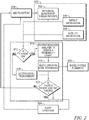
Fig. 2 is a flowchart showing the different steps performed to determine patient behavior; and -
Fig. 3 is a simplified schematic showing the model creation for determining patient behavior. - Referring to
Fig. 1 , a system 100 for a healthcare facility includes apatient support apparatus 122, such as a hospital bed that includes a patient support structure such as a frame that supports a surface or mattress. Thus, according to this disclosure a bed frame, a mattress or both are examples of things considered to be within the scope of the term "patient support structure." However, this disclosure is applicable to other types of patient support apparatuses and other patient support structures, including other types of beds, surgical tables, examination tables, stretchers, and the like. - The
patient support apparatus 122 includes a plurality ofsensors 312 that are used to determine the patient's mobility score. In some embodiments, these sensors may be load cells. In some embodiments, these sensors maybe air pressure bladders. In some embodiments, these sensors may be contact sensors. In some embodiments, these sensors maybe force sensing resistors. In some embodiments, a patient support apparatus may have multiple such sensors. Thesensors 312 are utilized to detect bed exit events by monitoring a pressure on thepatient support apparatus 122 and determining when the pressure is removed, which is indicative of the patient exiting the bed. Thesensors 312 may also be utilized to monitor when a patient is positioned on a side of thepatient support apparatus 122 and at risk for falling. - As shown in
Fig. 1 , in one embodiment, thepatient support apparatus 122, includescommunication circuitry 300, acontroller 302, and aninterface 324. Thecontroller 302 is capable of controlling operational functionality of thepatient support apparatus 122 and/or interpreting data signals from thevarious sensors 312. Thecommunication circuitry 300 is capable of establishing connections and facilitating communications to and from thepatient support apparatus 122. Thecontroller 302 is further configured to provide, or relay, status indications to a remote location, such as the nurse call system, via thecommunication circuitry 300. The status indications may include any type of indication of a component, or a patient relative to a component, of thepatient support apparatus 122. Thecommunication circuitry 300 may be embodied as any communication circuit, device, or collection thereof, capable of enabling communications over anetwork 116 between thepatient support apparatus 122 and ahospital information system 102. Thecommunication circuitry 300 may be configured to use any one or more communication technologies (e.g., wired or wireless communications) and associated protocols (e.g., Ethernet, Bluetooth®, Zigbee®, Wi-Fi®, WiMAX, etc.) to effect such communication. - In some embodiments, the patient support apparatus is connected to a bedside/patient
support apparatus connector 350 via thecommunications circuitry 300. The bedside/patient support apparatus connector may have a computing device and server to connect to thenetwork 116. - The
controller 302 is connected to various sensors capable of being monitored and interpreted by thecontroller 302, and various actuators capable of being controlled by thecontroller 302. Thecontroller 302 is configured to receive data (i.e., electrical signals) from the various sensors and components of thepatient support apparatus 122, and control the operation of the components of thepatient support apparatus 122 relative to the received data, as is known in the art. To do so, thecontroller 302 includes a number of electronic components commonly associated with controllers utilized in the control of electromechanical systems. For example, thecontroller 302 may include, amongst other components customarily included in such devices, aprocessor 304 and amemory device 306. Thememory device 306 may be, for example, a programmable read-only memory device ("PROM") including erasable PROM's (EPROM's or EEPROM's). In use, thememory device 306 is capable of storing, amongst other things, instructions in the form of, for example, a software routine (or routines) which, when executed by theprocessor 304, allow thecontroller 302 to control operation of the features of thepatient support apparatus 122. - The system 100 includes a
hospital information system 102 of one or more hospitals communicatively coupled over anetwork 116 to various care assets, such as apatient support apparatus 122. To facilitate the transfer of data and other network communications across thehospital information system 102, thehospital information system 102 includes a number ofcomputing devices 104. Each of thecomputing devices 104 may be embodied as any type of computation or computer device capable of performing the functions described herein, including, without limitation, a server (e.g., stand-alone, rack-mounted, blade, etc.), a network appliance (e.g., physical or virtual), a high-performance computing device, a web appliance, a distributed computing system, a computer, a processor-based system, a multiprocessor system, a smartphone, a tablet computer, a laptop computer, a notebook computer, and/or a mobile computing device. Theillustrative computing device 104 ofFig. 2 includes aprocessor 106 and amemory 110. Of course, thecomputing device 104 may include additional and/or alternative components, such as those commonly found in a computer (e.g., various input/output devices), in other embodiments. Additionally, in some embodiments, one or more of the illustrative components may be incorporated in, or otherwise form a portion of, another component. For example, thememory 110, or portions thereof, may be incorporated in theprocessor 106 in some embodiments. - The
processor 106 may be embodied as any type of processor capable of performing the functions described herein. For example, theprocessor 106 may be embodied as a single or multi-core processor(s), digital signal processor, microcontroller, or other processor or processing/controlling circuit. Thememory 110 may be embodied as any type of volatile or non-volatile memory or data storage capable of performing the functions described herein. In operation, thememory 110 may store various data and software used during operation of thecomputing device 104 such as operating systems, applications, programs, libraries, and drivers. Thememory 110 is communicatively coupled to theprocessor 106 via a I/O subsystem, which may be embodied as circuitry and/or components to facilitate input/output operations with theprocessor 106, thememory 110, and other components of thecomputing device 104. For example, the I/O subsystem may be embodied as, or otherwise include, memory controller hubs, input/output control hubs, firmware devices, communication links (i.e., point-to-point links, bus links, wires, cables, light guides, printed circuit board traces, etc.) and/or other components and subsystems to facilitate the input/output operations. - A
data storage device 112 may be embodied as any type of device or devices configured for short-term or long-term storage of data such as, for example, memory devices and circuits, memory cards, hard disk drives, solid-state drives, or other data storage devices. In use, as described below, thedata storage device 112 and/or thememory 110 may store security monitoring policies, configuration policies, or other, similar data.Communication circuitry 114 may be embodied as any communication circuit, device, or collection thereof, capable of enabling communications between thecomputing devices 104 and/or between one of thecomputing devices 104 and thepatient support apparatus 122. Thecommunication circuitry 114 may be configured to use any one or more communication technology (e.g., wired or wireless communications) and associated protocols (e.g., Ethernet, Bluetooth®, Wi-Fi®, WiMAX, etc.) to effect such communication. - The
computing devices 104 of thehospital information system 102 may be configured into separate subsystems for managing data and coordinating communications throughout thehospital information system 102. - The
network 116 may be embodied as any type of wired or wireless communication network, including cellular networks (e.g., Global System for Mobile Communications (GSM), 3G, Long Term Evolution (LTE), Worldwide Interoperability for Microwave Access (WiMAX), etc.), digital subscriber line (DSL) networks, cable networks (e.g., coaxial networks, fiber networks, etc.), telephony networks, local area networks (LANs) or wide area networks (WANs), global networks (e.g., the Internet), or any combination thereof. As previously described, at least a portion thepatient support apparatuses 122 may be in communication with thehospital information system 102 over thenetwork 116. Accordingly, thenetwork 116 may include any number of network devices (e.g., access points, routers, switches, servers, etc.) as needed to facilitate communications between thehospital information system 102 and thepatient support apparatus 122. - Referring still to
Fig. 1 , a real-time locating system (RTLS) 152 is provided to track the whereabouts of the patient.RTLS 152 includes apatient tag 154 worn by the patient and in communication with a multitude oftransceivers 156.Transceivers 156 may be dispersed throughout the patient room.Tag 154 andtransceiver 156 each include a housing that contains associated circuitry. The circuitry oftag 154 andtransceiver 156 includes for example a processor such as a microprocessor or microcontroller or the like, memory for storing software, and communications circuitry including a transmitter, a receiver and at least one antenna, for example.Tag 154 also includes structure to enable attachment to the patient. For example, tag 154 may include a necklace so that a caregiver can wear thetag 154 around their neck or may include a clip so that the caregiver can attach thetag 154 to their clothing. Thetag 154 may include a wristband so that thetag 154 can be worn on the wrists of the associated patients.Transceivers 156 each include mounting hardware, such as brackets or plates or the like, in some embodiments, to permit thetransceivers 156 to be mounted at fixed locations in the patient room with fasteners such as screws or the like. -
Transceiver 156 communicates wirelessly withtag 154 using radio frequency (RF). According to this disclosure,system 152 operates as a high-accuracy locating system which is able to determine the location of thetag 154 within one foot (30.48 cm) or less of the tag's actual location.System 152 is operable to determine the location of thetag 154 in 2-dimensional space. One example of a high-accuracy locating system contemplated by this disclosure is an ultra-wideband (UWB) locating system. UWB locating systems operate within the 3.1 gigahertz (GHz) to 10.6 GHz frequency range. Accordingly, thetag 154 is tracked by theRTLS 152 to monitor when the patient has left thepatient support apparatus 122. Data related to movement of the patient is transmitted over thenetwork 116 to thehospital information system 102. - Additionally,
cameras 150 may be positioned in the patient room and in communication with thenetwork 116. As such, thecameras 150 are utilized to monitor when the patient exits the beds. That is time-stamped video of the patient is captured by thecamera 150 and transmitted to thehospital information system 102, where the video is monitored for bed exits. In some embodiments, theprocessor 106 may operate instructions to track bed exit behavior in the video feeds. Therefore, data from thesensors 312, theRTLS 152, and thecameras 150 may all be utilized or individually utilized to track when the patient exits the bed. As set forth below, this data may be used to determine a bed exit schedule for the patient. - In the illustrated embodiment, the
processor 106 of thehospital information system 102 can access information gathered through the hospital information system from thememory 110. In some embodiments, the processor can access the current patient's daily routine. In some embodiments, the processor can access the current patient's medical schedule. In some embodiments, the processor can access the current patient's visiting hours. In some embodiments, the processor can access the historical behavior of similar patients. Theprocessor 106 can access mobility information of the current patient from thememory 110 of the patient support apparatus thememory 122 over the network 166. Theprocessor 106 in acomputing device 104 of thehospital information system 102 uses the current patient's information, the patient's mobility score, and the historical information from similar patients to perform analysis to determine the patient's behavior patterns. In some embodiments, theprocessor 304 of thepatient support device 122 can access all relevant information from thememory 110 of thecomputing device 104 which is a part of thehospital information system 102 over thenetwork 116 to do the analysis to predict patient behavior. In some embodiments, the patient support device is connected to a bedside connector that accesses the relevant information for patient behavior analysis over thenetwork 116. - In the illustrated embodiment
Fig. 2 , a flowchart shows the different steps performed to determine a patient behavior. Theprocessor 304 of apatient support apparatus 122 such as bed, can access historical data of similar patients (block 502) frommemory 306 or from thememory 110 over awireless network 116 atstep 500. The current patient's information such as medical schedule, routine, visiting hours (block 510), and mobility information (bock 504) can be accessed frommemory 306 or frommemory 110 over awireless network 116 atstep 500. Atstep 512, theprocessor 304 of apatient support apparatus 122 accessesmemory 306 or thememory 110 over awireless network 116 to decide it is the first assessment of the day. If it is the first assessment, steps 514, 516 and 520 are executed prior to step 522, else step 518 is executed prior to step 522. Atstep 518, theprocessor 304 accesses the model developed for the current patient that is stored inmemory 306 or frommemory 110 over awireless network 116. Atstep 514, weighted sum is used by theprocessor 306 to determine a probability chart for the current patient's behavior based on the information obtained instep 500. Anillustrative probability chart 600, is shown inFig. 3 . Atstep 516, a model to predict current patient's behavior is developed using machine learning (ML) techniques such as supervised learning or reinforcement learning. This model can be used to predict the current patient's behavior. In some embodiments, this behavior is bed exits. Atstep 520, the model developed is stored inmemory 306 or inmemory 110 over awireless network 116 or in both. Atstep 522, the model developed is used to make predictions about the current patient's bed exit behavior. If the patient is predicted to exit the bed, the prediction is communicated to the caregiver over thewireless network 116 atstep 524 and added to the historical database atstep 526. If the patient is not predicted to exit the bed, caregiver is not contacted and the information is added to the historical database atstep 522. The processor can access mobility and scheduling information of the patient from variouspatient support apparatuses 112controller 302 over thewireless network 116. In another embodiment, all the processing of information is done by theprocessor 106 in thecomputing device 104 which is a part of thehospital information system 102. Thememory processor 106 can access all relevant information frommemory 110 andmemory 306 over thenetwork 116. - The current patient's potential bed exits are monitored on
Day 1 of the current patient's stay in the hospital. Any changes to the initial assumptions based on the current patients schedule and the historical data of similar patients is monitored. Machine learning methods such as supervised learning or reinforcement learning is used to update the probability of bed exit and update the model making predictions. This builds a more accurate characterization of the patient's behavior. The refined model is used as the starting point for predictive events onDay 2. This process is repeated each day that the current patient is in the hospital room. - In some embodiments, patient diagnosis is entered as an input called patient condition to the model at the
user interface 324 onDay 1. Diagnosis is used to predict how the model will change over time. For example. A less critical diagnosis would expect the patient to become more mobile over time, a more critical diagnosis may expect the patient to deteriorate over time. The patient condition is used to update the probability of bed exit and update the model making predictions each day. This builds a more accurate characterization of the patient's behavior. The refined model is used as the starting point for predictive events onDay 2. This process is repeated each day that the current patient is in the hospital room. The current patient's data is integrated into historical data for use with next similar category patient and stored in thememory 306 of the patient support apparatus and also transmitted to thehospital information system 102 to be stored in thememory 110 and used by theprocessor 106. - The analysis done is used to provide alerts to the caregivers based on predicted events. Such alerts are proactive and planned care is provided to the patients based on the probability of the events that are likely to occur. These alerts are organized to reduce the cognitive burden by informing the caregivers about the most active time and are timed to reduce the occurrence of fall events. Such alerts are timed to improve patient safety and potential hospital liability and to increase staff effectiveness.
- Using the data, the system can observe and predict future bed exit events to alert caregivers before the event occurs. That is, the system uses the data to track patient movement throughout the patient's stay in the healthcare facility. The system pinpoints the patient's position in the patient room and determines what time the patient is typically in bed, when the patient uses the restroom, when the patient eats lunch, and when the patient generally is not in the patient bed. These behavioral patterns are utilized to predict when the patient may exit the bed. For example, the system may determine that the patient generally wakes up at the same time each day and build a customized rounding schedule to check on the patient 10-20 minutes before they usually wake up. In another example, the system may determine that the patient uses the restroom an average of 60 minutes after eating and proactively alert a caregiver that the patient may need assistance after eating. In yet another example, the system may determine that the patient exits the patient bed for an average of two hours. Using this data, caregivers may be alerted to check on the patient after a predetermined time.
- Although certain illustrative embodiments have been described in detail above, variations and modifications exist.
- Embodiments of the invention can be described with reference to the following numbered clauses, with preferred features laid out in the dependent clauses:
- 1. A method for inferring a patient's future behavior, comprising:
- acquiring data related to patient bed exits,
- analyzing the data related to patient bed exits to detect patterns in patient bed exit behavior,
- building a customized schedule of patient bed exit behavior to predict future patient bed exits, and
- notifying a caregiver when a future patient bed exit is to occur.
- 2. The method of
clause 1, wherein acquiring data related to patient bed exits includes acquiring data from a sensor in a patient support apparatus. - 3. The method of either
clause 1 orclause 2, wherein acquiring data related to patient bed exits includes acquiring data from a real time locating system. - 4. The method of any preceding clause, wherein acquiring data related to patient bed exits includes acquiring data from a camera in a patient room.
- 5. The method of any preceding clause, wherein acquiring data related to patient bed exits includes acquiring data related to the patient's medical schedule.
- 6. The method of any preceding clause, wherein acquiring data related to patient bed exits includes acquiring data related to the patient's mealtime schedule.
- 7. The method of any preceding clause, wherein acquiring data related to patient bed exits includes acquiring data related to the patient's visiting hours schedule.
- 8. The method of any preceding clause, further comprising combining historical data from similar patients to the data related to patient bed exits to determine a model that predicts future patient bed exits.
- 9. The method of any preceding clause, wherein notifying a caregiver when a future patient bed exit is to occur further comprises notifying a caregiver a predetermined time before the future patient bed exit is to occur.
- 10. The method of any preceding clause, further comprising comparing a patient's current behavior to a patient's predicted behavior.
- 11. The method of
clause 10, further comprising updating the customized schedule based on differences between a patient's current behavior and a patient's predicted behavior. - 12. The method of any preceding clause, wherein notifying a caregiver when a future patient bed exit is to occur further comprises notifying the caregiver before the patient wakes up.
- 13. The method of any preceding clause, wherein notifying a caregiver when a future patient bed exit is to occur further comprises notifying the caregiver before the patient uses the restroom.
- 14. A system for inferring a patient's future behavior, comprising:
- a patient support apparatus,
- a data acquisition system to track data related to patient bed exits from the patient support apparatus, and
- a controller in communication with the patient support apparatus, the controller including a processor and a non-transitory memory device, the memory device including instructions that, when executed by the processor, acquire data related to patient bed exits, analyze the data related to patient bed exits to detect patterns in patient bed exit behavior, build a customized schedule of patient bed exit behavior to predict future patient bed exits, and notify a caregiver when a future patient bed exit is to occur.
- 15. The system of clause 14, wherein the data acquisition system further comprises a sensor in a patient support apparatus.
- 16. The system of either clause 14 or clause 15, wherein the data acquisition system further comprises a real time locating system.
- 17. The system of any one of clauses 14 to 16, wherein the data acquisition system further comprises a camera in a patient room.
- 18. The system of any one of clauses 14 to 17, wherein the data related to patient bed exits includes data related to the patient's medical schedule.
- 19. The system of any one of clauses 14 to 18, wherein the data related to patient bed exits includes data related to the patient's mealtime schedule.
- 20. The system of any one of clauses 14 to 19, wherein the data related to patient bed exits includes data related to the patient's visiting hours schedule.
- 21. The system of any one of clauses 14 to 20, wherein historical data from similar patients is compared to the data related to patient bed exits to determine a model that predicts future patient bed exits.
- 22. The system of any one of clauses 14 to 21, wherein the caregiver is notified a predetermined time before the future patient bed exit is to occur.
- 23. The system of any one of clauses 14 to 22, wherein a patient's current behavior is compared to a patient's predicted behavior to update the customized schedule.
- 24. The system of any one of clauses 14 to 23, wherein the caregiver is notified before the patient wakes up.
- 25. The system of any one of clauses 14 to 24, wherein the caregiver is notified before the patient uses the restroom.
Claims (6)
- A system for inferring a patient's future behavior, comprising:a patient support apparatus configured to support a patient,a data acquisition system in communication with the patient support apparatus via a network, the data acquisition system configured to automatically track data related to patient bed exits from the patient support apparatus, wherein the data acquisition system includes at least one of a sensor to detect movement of the patient on the patient support apparatus, a real time locating system to detect a location of the patient, and a camera to monitor the patient with time-stamped video,a hospital information system in communication with the patient support apparatus via the network, the hospital information system including a memory that stores scheduling data related to the patient, wherein the scheduling data related to the patient includes at least one of a patient medical schedule, a patient mealtime schedule, and a patient visiting hour schedule, anda controller in communication with the patient support apparatus, the controller including a processor and a non-transitory memory device, the memory device including instructions that, when executed by the processor, acquire the data related to patient bed exits from the data acquisition system, acquire the scheduling data related to the patient from the hospital information system, automatically analyze the data related to patient bed exits and the scheduling data related to the patient to detect patterns in patient bed exit behavior, automatically develop a model of patient bed exit behavior to predict future patient bed exits, automatically store the model in the hospital information system, automatically access the hospital information system to determine when a future patient bed exit is to occur, and automatically alert a caregiver over the network when the future patient bed exit is to occur.
- The system of claim 1, wherein historical data from similar patients is automatically compared to the data related to patient bed exits to develop the model of patient bed exit behavior.
- The system of either claim 1 or claim 2, wherein the caregiver is automatically alerted over the network a predetermined time before the future patient bed exit is to occur.
- The system of any preceding claim, wherein a patient's current behavior is automatically compared to a patient's predicted behavior to update the model of patient bed exit behavior.
- The system of any preceding claim, wherein the caregiver is automatically alerted over the network before the patient wakes up.
- The system of any preceding claim, wherein the caregiver is automatically alerted over the network before the patient uses the restroom.
Applications Claiming Priority (1)
| Application Number | Priority Date | Filing Date | Title |
|---|---|---|---|
| US202062987999P | 2020-03-11 | 2020-03-11 |
Publications (1)
| Publication Number | Publication Date |
|---|---|
| EP3878362A1 true EP3878362A1 (en) | 2021-09-15 |
Family
ID=74859339
Family Applications (1)
| Application Number | Title | Priority Date | Filing Date |
|---|---|---|---|
| EP21161026.6A Pending EP3878362A1 (en) | 2020-03-11 | 2021-03-05 | Bed exit prediction based on patient behavior patterns |
Country Status (3)
| Country | Link |
|---|---|
| US (2) | US20210287791A1 (en) |
| EP (1) | EP3878362A1 (en) |
| CN (1) | CN113393923A (en) |
Cited By (1)
| Publication number | Priority date | Publication date | Assignee | Title |
|---|---|---|---|---|
| EP4160604A1 (en) * | 2021-09-30 | 2023-04-05 | Nihon Kohden Corporation | Fluid balance management system, prediction device, learned model generation device, and learned model generation method |
Citations (2)
| Publication number | Priority date | Publication date | Assignee | Title |
|---|---|---|---|---|
| US20070136102A1 (en) * | 2005-12-09 | 2007-06-14 | Valence Broadband, Inc. | Methods for refining patient, staff and visitor profiles used in monitoring quality and performance at a healthcare facility |
| EP2666406A2 (en) * | 2012-05-22 | 2013-11-27 | Hill-Rom Services, Inc. | Occupant egress prediction systems, methods and devices |
Family Cites Families (18)
| Publication number | Priority date | Publication date | Assignee | Title |
|---|---|---|---|---|
| US7620444B2 (en) * | 2002-10-05 | 2009-11-17 | General Electric Company | Systems and methods for improving usability of images for medical applications |
| US7852208B2 (en) * | 2004-08-02 | 2010-12-14 | Hill-Rom Services, Inc. | Wireless bed connectivity |
| JP2007072964A (en) * | 2005-09-09 | 2007-03-22 | Ishihara Sangyo:Kk | Bed-leaving prediction automatic sensing and notification method, and its automatic sensing and notification system |
| US20070132597A1 (en) * | 2005-12-09 | 2007-06-14 | Valence Broadband, Inc. | Methods and systems for monitoring patient support exiting and initiating response |
| US7911348B2 (en) * | 2005-12-09 | 2011-03-22 | Bee Cave, LLC. | Methods for refining patient, staff and visitor profiles used in monitoring quality and performance at a healthcare facility |
| EP2335232B1 (en) * | 2008-09-10 | 2012-08-15 | Koninklijke Philips Electronics N.V. | Bed exit warning system |
| US20150261924A1 (en) * | 2012-10-22 | 2015-09-17 | Koninklijke Philips N.V. | Healthcare system and method |
| JP5791156B2 (en) * | 2012-11-20 | 2015-10-07 | 公立大学法人秋田県立大学 | Intelligent bed and bed prediction sensor system |
| JP6198308B2 (en) * | 2013-09-20 | 2017-09-20 | 株式会社ケアコム | Patient monitoring system |
| US11074802B2 (en) * | 2017-02-02 | 2021-07-27 | Hill-Rom Services, Inc. | Method and apparatus for automatic event prediction |
| US10517511B2 (en) * | 2017-06-14 | 2019-12-31 | Hello Nurse Medical Innovations, Inc. | Patient off-bed notification system |
| TWM552645U (en) * | 2017-06-14 | 2017-12-01 | Hello Nurse Medical Innovation Inc | Patient out of bed notification system |
| WO2020026171A1 (en) * | 2018-07-31 | 2020-02-06 | Hill-Rom Services, Inc. | Sensing system for patient support apparatus |
| TWM569913U (en) * | 2018-08-10 | 2018-11-11 | 商之器科技股份有限公司 | Bed exit prediction system with load cell sensor |
| US11800993B2 (en) * | 2019-06-28 | 2023-10-31 | Hill-Rom Services, Inc. | Exit monitoring system for patient support apparatus |
| US20210183504A1 (en) * | 2019-12-17 | 2021-06-17 | Hill-Rom Services, Inc. | Patient bed exit prediction |
| US20230008323A1 (en) * | 2021-07-12 | 2023-01-12 | GE Precision Healthcare LLC | Systems and methods for predicting and preventing patient departures from bed |
| US20230329583A1 (en) * | 2022-04-13 | 2023-10-19 | Sleep Number Corporation | Detecting and preventing sleepwalking events |
-
2021
- 2021-02-15 US US17/175,917 patent/US20210287791A1/en not_active Abandoned
- 2021-02-26 CN CN202110220335.4A patent/CN113393923A/en active Pending
- 2021-03-05 EP EP21161026.6A patent/EP3878362A1/en active Pending
-
2025
- 2025-08-13 US US19/298,612 patent/US20250372247A1/en active Pending
Patent Citations (2)
| Publication number | Priority date | Publication date | Assignee | Title |
|---|---|---|---|---|
| US20070136102A1 (en) * | 2005-12-09 | 2007-06-14 | Valence Broadband, Inc. | Methods for refining patient, staff and visitor profiles used in monitoring quality and performance at a healthcare facility |
| EP2666406A2 (en) * | 2012-05-22 | 2013-11-27 | Hill-Rom Services, Inc. | Occupant egress prediction systems, methods and devices |
Cited By (2)
| Publication number | Priority date | Publication date | Assignee | Title |
|---|---|---|---|---|
| EP4160604A1 (en) * | 2021-09-30 | 2023-04-05 | Nihon Kohden Corporation | Fluid balance management system, prediction device, learned model generation device, and learned model generation method |
| US12332616B2 (en) | 2021-09-30 | 2025-06-17 | Nihon Kohden Corporation | Fluid balance management system, prediction device, learned model generation device, and learned model generation method |
Also Published As
| Publication number | Publication date |
|---|---|
| CN113393923A (en) | 2021-09-14 |
| US20250372247A1 (en) | 2025-12-04 |
| US20210287791A1 (en) | 2021-09-16 |
Similar Documents
| Publication | Publication Date | Title |
|---|---|---|
| US11830336B2 (en) | Patient risk notification system | |
| CN104582562B (en) | Connected patient monitoring system and method providing patient-centric smart monitoring service | |
| US10543137B2 (en) | Patient support apparatus with remote communications | |
| JP6010558B2 (en) | Detection of patient deterioration | |
| CA3122375A1 (en) | Systems and methods for prevention of pressure ulcers | |
| US11626000B2 (en) | Patient care system | |
| US20250372247A1 (en) | Bed exit prediction based on patient behavior patterns | |
| US20190074088A1 (en) | Systems And Methods For Monitoring And/Or Managing A Person's Position Using An Accumulated Timer | |
| CN112587099A (en) | Personalized vital sign monitor | |
| EP3098739A1 (en) | Healthcare communication system | |
| US20200058209A1 (en) | System and method for automated health monitoring | |
| JP6368512B2 (en) | Server device, watching system, and program | |
| Sarma Dhulipala et al. | Cardiac care assistance using self configured sensor network—a remote patient monitoring system | |
| CN107088242B (en) | Automated anesthesia pump to improve anesthesiologist mobility | |
| HK1209245A1 (en) | Network-based healthcare monitoring system | |
| Rohankumar et al. | A smart health care ecosystem |
Legal Events
| Date | Code | Title | Description |
|---|---|---|---|
| PUAI | Public reference made under article 153(3) epc to a published international application that has entered the european phase |
Free format text: ORIGINAL CODE: 0009012 |
|
| STAA | Information on the status of an ep patent application or granted ep patent |
Free format text: STATUS: THE APPLICATION HAS BEEN PUBLISHED |
|
| AK | Designated contracting states |
Kind code of ref document: A1 Designated state(s): AL AT BE BG CH CY CZ DE DK EE ES FI FR GB GR HR HU IE IS IT LI LT LU LV MC MK MT NL NO PL PT RO RS SE SI SK SM TR |
|
| STAA | Information on the status of an ep patent application or granted ep patent |
Free format text: STATUS: REQUEST FOR EXAMINATION WAS MADE |
|
| 17P | Request for examination filed |
Effective date: 20220315 |
|
| RBV | Designated contracting states (corrected) |
Designated state(s): AL AT BE BG CH CY CZ DE DK EE ES FI FR GB GR HR HU IE IS IT LI LT LU LV MC MK MT NL NO PL PT RO RS SE SI SK SM TR |
|
| STAA | Information on the status of an ep patent application or granted ep patent |
Free format text: STATUS: EXAMINATION IS IN PROGRESS |
|
| 17Q | First examination report despatched |
Effective date: 20240816 |