EP3878350A1 - Sheath for an endoscope - Google Patents
Sheath for an endoscope Download PDFInfo
- Publication number
- EP3878350A1 EP3878350A1 EP21172251.7A EP21172251A EP3878350A1 EP 3878350 A1 EP3878350 A1 EP 3878350A1 EP 21172251 A EP21172251 A EP 21172251A EP 3878350 A1 EP3878350 A1 EP 3878350A1
- Authority
- EP
- European Patent Office
- Prior art keywords
- sheath
- radially expandable
- expandable flexible
- sheath body
- flexible regions
- Prior art date
- Legal status (The legal status is an assumption and is not a legal conclusion. Google has not performed a legal analysis and makes no representation as to the accuracy of the status listed.)
- Pending
Links
Images



Classifications
-
- A—HUMAN NECESSITIES
- A61—MEDICAL OR VETERINARY SCIENCE; HYGIENE
- A61B—DIAGNOSIS; SURGERY; IDENTIFICATION
- A61B1/00—Instruments for performing medical examinations of the interior of cavities or tubes of the body by visual or photographical inspection, e.g. endoscopes; Illuminating arrangements therefor
- A61B1/00131—Accessories for endoscopes
- A61B1/00135—Oversleeves mounted on the endoscope prior to insertion
-
- A—HUMAN NECESSITIES
- A61—MEDICAL OR VETERINARY SCIENCE; HYGIENE
- A61B—DIAGNOSIS; SURGERY; IDENTIFICATION
- A61B1/00—Instruments for performing medical examinations of the interior of cavities or tubes of the body by visual or photographical inspection, e.g. endoscopes; Illuminating arrangements therefor
- A61B1/00064—Constructional details of the endoscope body
- A61B1/00071—Insertion part of the endoscope body
- A61B1/00073—Insertion part of the endoscope body with externally grooved shaft
-
- A—HUMAN NECESSITIES
- A61—MEDICAL OR VETERINARY SCIENCE; HYGIENE
- A61B—DIAGNOSIS; SURGERY; IDENTIFICATION
- A61B1/00—Instruments for performing medical examinations of the interior of cavities or tubes of the body by visual or photographical inspection, e.g. endoscopes; Illuminating arrangements therefor
- A61B1/00064—Constructional details of the endoscope body
- A61B1/00071—Insertion part of the endoscope body
- A61B1/0008—Insertion part of the endoscope body characterised by distal tip features
- A61B1/00082—Balloons
-
- A—HUMAN NECESSITIES
- A61—MEDICAL OR VETERINARY SCIENCE; HYGIENE
- A61B—DIAGNOSIS; SURGERY; IDENTIFICATION
- A61B1/00—Instruments for performing medical examinations of the interior of cavities or tubes of the body by visual or photographical inspection, e.g. endoscopes; Illuminating arrangements therefor
- A61B1/00064—Constructional details of the endoscope body
- A61B1/00071—Insertion part of the endoscope body
- A61B1/0008—Insertion part of the endoscope body characterised by distal tip features
- A61B1/00094—Suction openings
-
- A—HUMAN NECESSITIES
- A61—MEDICAL OR VETERINARY SCIENCE; HYGIENE
- A61B—DIAGNOSIS; SURGERY; IDENTIFICATION
- A61B1/00—Instruments for performing medical examinations of the interior of cavities or tubes of the body by visual or photographical inspection, e.g. endoscopes; Illuminating arrangements therefor
- A61B1/00131—Accessories for endoscopes
- A61B1/0014—Fastening element for attaching accessories to the outside of an endoscope, e.g. clips, clamps or bands
-
- A—HUMAN NECESSITIES
- A61—MEDICAL OR VETERINARY SCIENCE; HYGIENE
- A61B—DIAGNOSIS; SURGERY; IDENTIFICATION
- A61B1/00—Instruments for performing medical examinations of the interior of cavities or tubes of the body by visual or photographical inspection, e.g. endoscopes; Illuminating arrangements therefor
- A61B1/012—Instruments for performing medical examinations of the interior of cavities or tubes of the body by visual or photographical inspection, e.g. endoscopes; Illuminating arrangements therefor characterised by internal passages or accessories therefor
- A61B1/015—Control of fluid supply or evacuation
-
- A—HUMAN NECESSITIES
- A61—MEDICAL OR VETERINARY SCIENCE; HYGIENE
- A61B—DIAGNOSIS; SURGERY; IDENTIFICATION
- A61B1/00—Instruments for performing medical examinations of the interior of cavities or tubes of the body by visual or photographical inspection, e.g. endoscopes; Illuminating arrangements therefor
- A61B1/307—Instruments for performing medical examinations of the interior of cavities or tubes of the body by visual or photographical inspection, e.g. endoscopes; Illuminating arrangements therefor for the urinary organs, e.g. urethroscopes, cystoscopes
-
- A—HUMAN NECESSITIES
- A61—MEDICAL OR VETERINARY SCIENCE; HYGIENE
- A61B—DIAGNOSIS; SURGERY; IDENTIFICATION
- A61B17/00—Surgical instruments, devices or methods
- A61B17/22—Implements for squeezing-off ulcers or the like on inner organs of the body; Implements for scraping-out cavities of body organs, e.g. bones; for invasive removal or destruction of calculus using mechanical vibrations; for removing obstructions in blood vessels, not otherwise provided for
-
- A—HUMAN NECESSITIES
- A61—MEDICAL OR VETERINARY SCIENCE; HYGIENE
- A61M—DEVICES FOR INTRODUCING MEDIA INTO, OR ONTO, THE BODY; DEVICES FOR TRANSDUCING BODY MEDIA OR FOR TAKING MEDIA FROM THE BODY; DEVICES FOR PRODUCING OR ENDING SLEEP OR STUPOR
- A61M1/00—Suction or pumping devices for medical purposes; Devices for carrying-off, for treatment of, or for carrying-over, body-liquids; Drainage systems
- A61M1/71—Suction drainage systems
- A61M1/77—Suction-irrigation systems
-
- A—HUMAN NECESSITIES
- A61—MEDICAL OR VETERINARY SCIENCE; HYGIENE
- A61M—DEVICES FOR INTRODUCING MEDIA INTO, OR ONTO, THE BODY; DEVICES FOR TRANSDUCING BODY MEDIA OR FOR TAKING MEDIA FROM THE BODY; DEVICES FOR PRODUCING OR ENDING SLEEP OR STUPOR
- A61M25/00—Catheters; Hollow probes
- A61M25/01—Introducing, guiding, advancing, emplacing or holding catheters
- A61M25/06—Body-piercing guide needles or the like
- A61M25/0662—Guide tubes
-
- A—HUMAN NECESSITIES
- A61—MEDICAL OR VETERINARY SCIENCE; HYGIENE
- A61M—DEVICES FOR INTRODUCING MEDIA INTO, OR ONTO, THE BODY; DEVICES FOR TRANSDUCING BODY MEDIA OR FOR TAKING MEDIA FROM THE BODY; DEVICES FOR PRODUCING OR ENDING SLEEP OR STUPOR
- A61M3/00—Medical syringes, e.g. enemata; Irrigators
- A61M3/02—Enemata; Irrigators
- A61M3/0279—Cannula; Nozzles; Tips; their connection means
- A61M3/0283—Cannula; Nozzles; Tips; their connection means with at least two inner passageways, a first one for irrigating and a second for evacuating
-
- A—HUMAN NECESSITIES
- A61—MEDICAL OR VETERINARY SCIENCE; HYGIENE
- A61B—DIAGNOSIS; SURGERY; IDENTIFICATION
- A61B17/00—Surgical instruments, devices or methods
- A61B2017/00017—Electrical control of surgical instruments
- A61B2017/00022—Sensing or detecting at the treatment site
-
- A—HUMAN NECESSITIES
- A61—MEDICAL OR VETERINARY SCIENCE; HYGIENE
- A61B—DIAGNOSIS; SURGERY; IDENTIFICATION
- A61B17/00—Surgical instruments, devices or methods
- A61B2017/00017—Electrical control of surgical instruments
- A61B2017/00022—Sensing or detecting at the treatment site
- A61B2017/00084—Temperature
-
- A—HUMAN NECESSITIES
- A61—MEDICAL OR VETERINARY SCIENCE; HYGIENE
- A61B—DIAGNOSIS; SURGERY; IDENTIFICATION
- A61B17/00—Surgical instruments, devices or methods
- A61B17/22—Implements for squeezing-off ulcers or the like on inner organs of the body; Implements for scraping-out cavities of body organs, e.g. bones; for invasive removal or destruction of calculus using mechanical vibrations; for removing obstructions in blood vessels, not otherwise provided for
- A61B2017/22051—Implements for squeezing-off ulcers or the like on inner organs of the body; Implements for scraping-out cavities of body organs, e.g. bones; for invasive removal or destruction of calculus using mechanical vibrations; for removing obstructions in blood vessels, not otherwise provided for with an inflatable part, e.g. balloon, for positioning, blocking, or immobilisation
-
- A—HUMAN NECESSITIES
- A61—MEDICAL OR VETERINARY SCIENCE; HYGIENE
- A61B—DIAGNOSIS; SURGERY; IDENTIFICATION
- A61B17/00—Surgical instruments, devices or methods
- A61B17/22—Implements for squeezing-off ulcers or the like on inner organs of the body; Implements for scraping-out cavities of body organs, e.g. bones; for invasive removal or destruction of calculus using mechanical vibrations; for removing obstructions in blood vessels, not otherwise provided for
- A61B2017/22051—Implements for squeezing-off ulcers or the like on inner organs of the body; Implements for scraping-out cavities of body organs, e.g. bones; for invasive removal or destruction of calculus using mechanical vibrations; for removing obstructions in blood vessels, not otherwise provided for with an inflatable part, e.g. balloon, for positioning, blocking, or immobilisation
- A61B2017/22065—Functions of balloons
- A61B2017/22069—Immobilising; Stabilising
-
- A—HUMAN NECESSITIES
- A61—MEDICAL OR VETERINARY SCIENCE; HYGIENE
- A61B—DIAGNOSIS; SURGERY; IDENTIFICATION
- A61B2217/00—General characteristics of surgical instruments
- A61B2217/002—Auxiliary appliance
- A61B2217/007—Auxiliary appliance with irrigation system
-
- A—HUMAN NECESSITIES
- A61—MEDICAL OR VETERINARY SCIENCE; HYGIENE
- A61M—DEVICES FOR INTRODUCING MEDIA INTO, OR ONTO, THE BODY; DEVICES FOR TRANSDUCING BODY MEDIA OR FOR TAKING MEDIA FROM THE BODY; DEVICES FOR PRODUCING OR ENDING SLEEP OR STUPOR
- A61M1/00—Suction or pumping devices for medical purposes; Devices for carrying-off, for treatment of, or for carrying-over, body-liquids; Drainage systems
- A61M1/71—Suction drainage systems
- A61M1/77—Suction-irrigation systems
- A61M1/772—Suction-irrigation systems operating alternately
-
- A—HUMAN NECESSITIES
- A61—MEDICAL OR VETERINARY SCIENCE; HYGIENE
- A61M—DEVICES FOR INTRODUCING MEDIA INTO, OR ONTO, THE BODY; DEVICES FOR TRANSDUCING BODY MEDIA OR FOR TAKING MEDIA FROM THE BODY; DEVICES FOR PRODUCING OR ENDING SLEEP OR STUPOR
- A61M25/00—Catheters; Hollow probes
- A61M25/0021—Catheters; Hollow probes characterised by the form of the tubing
- A61M25/0023—Catheters; Hollow probes characterised by the form of the tubing by the form of the lumen, e.g. cross-section, variable diameter
- A61M2025/0024—Expandable catheters or sheaths
-
- A—HUMAN NECESSITIES
- A61—MEDICAL OR VETERINARY SCIENCE; HYGIENE
- A61M—DEVICES FOR INTRODUCING MEDIA INTO, OR ONTO, THE BODY; DEVICES FOR TRANSDUCING BODY MEDIA OR FOR TAKING MEDIA FROM THE BODY; DEVICES FOR PRODUCING OR ENDING SLEEP OR STUPOR
- A61M25/00—Catheters; Hollow probes
- A61M25/0021—Catheters; Hollow probes characterised by the form of the tubing
- A61M25/0023—Catheters; Hollow probes characterised by the form of the tubing by the form of the lumen, e.g. cross-section, variable diameter
- A61M25/0026—Multi-lumen catheters with stationary elements
- A61M2025/004—Multi-lumen catheters with stationary elements characterized by lumina being arranged circumferentially
-
- A—HUMAN NECESSITIES
- A61—MEDICAL OR VETERINARY SCIENCE; HYGIENE
- A61M—DEVICES FOR INTRODUCING MEDIA INTO, OR ONTO, THE BODY; DEVICES FOR TRANSDUCING BODY MEDIA OR FOR TAKING MEDIA FROM THE BODY; DEVICES FOR PRODUCING OR ENDING SLEEP OR STUPOR
- A61M25/00—Catheters; Hollow probes
- A61M25/01—Introducing, guiding, advancing, emplacing or holding catheters
- A61M25/06—Body-piercing guide needles or the like
- A61M25/0662—Guide tubes
- A61M2025/0681—Systems with catheter and outer tubing, e.g. sheath, sleeve or guide tube
-
- A—HUMAN NECESSITIES
- A61—MEDICAL OR VETERINARY SCIENCE; HYGIENE
- A61M—DEVICES FOR INTRODUCING MEDIA INTO, OR ONTO, THE BODY; DEVICES FOR TRANSDUCING BODY MEDIA OR FOR TAKING MEDIA FROM THE BODY; DEVICES FOR PRODUCING OR ENDING SLEEP OR STUPOR
- A61M2205/00—General characteristics of the apparatus
- A61M2205/33—Controlling, regulating or measuring
- A61M2205/3331—Pressure; Flow
- A61M2205/3334—Measuring or controlling the flow rate
-
- A—HUMAN NECESSITIES
- A61—MEDICAL OR VETERINARY SCIENCE; HYGIENE
- A61M—DEVICES FOR INTRODUCING MEDIA INTO, OR ONTO, THE BODY; DEVICES FOR TRANSDUCING BODY MEDIA OR FOR TAKING MEDIA FROM THE BODY; DEVICES FOR PRODUCING OR ENDING SLEEP OR STUPOR
- A61M2205/00—General characteristics of the apparatus
- A61M2205/33—Controlling, regulating or measuring
- A61M2205/3368—Temperature
-
- A—HUMAN NECESSITIES
- A61—MEDICAL OR VETERINARY SCIENCE; HYGIENE
- A61M—DEVICES FOR INTRODUCING MEDIA INTO, OR ONTO, THE BODY; DEVICES FOR TRANSDUCING BODY MEDIA OR FOR TAKING MEDIA FROM THE BODY; DEVICES FOR PRODUCING OR ENDING SLEEP OR STUPOR
- A61M3/00—Medical syringes, e.g. enemata; Irrigators
- A61M3/02—Enemata; Irrigators
- A61M3/0279—Cannula; Nozzles; Tips; their connection means
Definitions
- the present disclosure relates to medical device. More specifically, the present disclosure relates to a sheath that is capable of receiving an insertion tube of an endoscope.
- perforation or avulsion of the ureter is a possible complication during ureteroscopy, which may result in the loss and removal of the associated renal unit.
- the force required to avulse or perforate a human ureter is not very large.
- a study in the "Journal of Urology, vol. 70(3), p. 592” states the force required to perforate a human ureter with a needle is 1.05 ⁇ 0.29 Ib m or 0.79 ⁇ 0.25 Ib m with a guidewire.
- the sheath includes a sheath body, an inflow port at a proximal end of the sheath body, an outflow port at the proximal end of the sheath body, and a plurality of radially expandable flexible members which extend along a length of the sheath body.
- the plurality of radially expandable flexible members may be attached to the sheath body at a plurality of anchor points along the length of the sheath body.
- the plurality of radially expandable flexible members may expand during active fluid inflow.
- the radially expandable flexible members may be spaced apart along the sheath body to define one or more isolated spaces that extend between adjacent radially expandable flexible members when the radially expandable flexible members are inflated within a body passage.
- the sheath may be further characterized by one or any combination of the features described herein, such as, for example: the sheath further includes a plurality of rigid channels which extend along the length of the sheath body; the channels of the plurality of rigid channels are attached to the sheath body at a plurality of anchor points; the channels of the plurality of rigid channels are attached to the plurality of expandable flexible members at a plurality of anchor points; the channels of the plurality of rigid channels are spaced apart to define one or more isolated spaces with the channels that extend along the length of the sheath body; fluid flows from a distal end of the sheath body though the isolated spaces to the outflow port during active fluid outflow; active fluid outflow removes debris from a body region; the active fluid inflow provides irrigation fluid to a body region; the sheath further includes a plurality of ribs which extend along the length of the sheath body; the ribs of the plurality of ribs are spaced apart to define one or more isolated spaces between adjacent ribs that extend
- the present disclosure provides a method of irrigating a body region including one or more of the following steps: sliding a sheath body over an insertion tube of an endoscope; and pumping fluid into an inflow port at a proximal end of the sheath body to expand a plurality of radially expandable flexible members which extend along a length of the sheath body during active fluid inflow.
- FIGs. 1A, 1B , 2A and 2B a sheath 12 receiving an insertion tube 14 of an endoscope 10 in accordance with the principles of the present invention is illustrated in FIGs. 1A, 1B , 2A and 2B .
- the endoscope 10 further includes a handle portion 18 and a connector 16 that connects the handle portion 18 with the sheath 12 and insertion tube 14.
- the handle portion 18 may include components for operating the endoscope 10, such as, for optical components for imaging, fluid flow components for irrigation and control components for movement of the insertion tube 14 and sheath 12.
- the connector 16 includes an inlet 20 that connects with a tube 22.
- the tube 22 provides fluid that flows through the inlet 20 into the sheath 12.
- the insertion tube 14 and sheath 12 are inserted into a body passage such as a ureter 30.
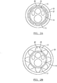
- the sheath 12 includes a plurality of radially expandable flexible members 26 which extend along the length of a sheath body 13. As shown in FIG. 2B , each of the plurality of radially expandable flexible members 26 has a generally petal shape when expanded.
- the plurality of radially expandable flexible members 26 are attached to the sheath body 13 at a plurality of anchor points along the length of the sheath body.
- the plurality of radially expandable flexible members 26 expand during active fluid inflow from the inlet 20 to a distal end 31 of the sheath 12.
- the radially expandable flexible members 26 are spaced apart along the sheath body 13 to define one or more isolated spaces 28 that extend between adjacent radially expandable flexible members 26 when the radially expandable flexible members are inflated within the ureter 30.
- a region 32 including a plurality of outflow channels extends along the length of the sheath body 13.
- the region 32 may remove debris from a body region during active fluid outflow.
- an operator of the endoscope 10 When the endoscope 10 is employed for a medical procedure, an operator of the endoscope 10, such as a physician, inserts the insertion tube 14 and the sheath 12 through a body passage such as the ureter 30 so that the distal end 31 of the sheath 12 is positioned at an anatomical region of interest.
- the anatomical region of interest may contain stone fragments that are removed during the medical procedure.
- the physician may use the optical components associated with the endoscope 10 to provide guidance of the insertion tube 14 through the ureter and to image the anatomical region of interest.
- the physician may also employ the control components associated with the endoscope 10 to maneuver the insertion tube 14.
- the stone fragments may be fragments produced by a prior procedure, or the stone fragments may be produced during the use of the endoscope 10.
- the pressure of the fluid expands the radially expandable flexible members 20 so that the fluid flows through the isolated spaces 28.
- the fluid flows out of the distal end 31 to the anatomical region of interest.
- the physician is able to employ the insertion tube 14 along with the sheath 12 to irrigate the anatomical region of interest.
- suction can be applied through the outflow channels 32 to remove fluid and/or debris from the anatomical region of interest.
- the sheath 112 includes a plurality of radially expandable flexible members 126 which extend along the length of a sheath body 113.
- the plurality of radially expandable flexible members 126 are attached to the sheath body at a plurality of anchor points 140 along the length of the sheath body 113.
- the plurality of radially expandable flexible members 126 expand during active fluid inflow from the inlet 20 to the distal end of the sheath 112.
- the radially expandable flexible members 126 are spaced apart along the sheath body 13 to define one or more isolated spaces 128 that extend between adjacent radially expandable flexible members 126 when the radially expandable flexible members are inflated within the ureter 30. When expanded, the radially expandable flexible members 126 generally form the shape of a semi-circle.
- a plurality of outflow channels 32 extend along the length of the sheath body 113.
- the outflow channels 32 remove debris from a body region during active fluid outflow.
- the sheath 112 also includes a plurality of radially expanding members 142 attached to the sheath body 113 at a plurality of anchor points 140 along the length of the sheath body 13.
- the radially expandable flexible members 142 are spaced apart along the sheath body 113 to define one or more isolated spaces 144 that extend between adjacent radially expandable flexible members 146 when the radially expandable flexible members 142 are inflated within the ureter 30.
- the plurality of radially expandable flexible members 142 expand during active fluid inflow from the proximal end of the sheath to the distal end of the sheath 12 through the inlet 20 and into a region of interest.
- the sheath 212 includes a plurality of radially expandable flexible members 226 which extend along the length of a sheath body 213.
- the plurality of radially expandable flexible members 226 are attached to the sheath body at a plurality of anchor points 240 along the length of the sheath body 213.
- the plurality of radially expandable flexible members 226 expand during active fluid inflow from the inlet 20 to the distal end of the sheath 212.
- the radially expandable flexible members 226 are spaced apart along the sheath body 213 to define one or more isolated spaces 228 that extend between adjacent radially expandable flexible members 226 when the radially expandable flexible members are inflated within the ureter 30.
- the sheath 212 also includes a plurality of ribs 142 that extend along the length of the sheath body 213.
- the plurality of ribs 142 may be rigid in nature such that they do not collapse when external pressure is applied.
- a plurality of outflow channels 246 extend along the length of the sheath body 213.
- the plurality of ribs 142 define a plurality of outflow channels 244 that extends along the length of the sheath body 213. The outflow channels 244 and 246 remove debris from a body region during active fluid outflow.
- FIG. 5 illustrates yet another sheath 312 in accordance with the principles of the present invention.
- the sheath 12 includes a plurality of radially expandable flexible members 326 which extend along the length of a sheath body 313.
- Each of the plurality of radially expandable flexible members 326 has a generally semicircular cross-sectional shape when expanded as shown in FIG. 5 .
- the plurality of radially expandable flexible members 326 are attached to the sheath body 313 at a plurality of anchor points along the length of the sheath body 313.
- the plurality of radially expandable flexible members 326 expand during active fluid inflow from the inlet 20 to the distal end of the sheath 12 and into a region of interest.
- the radially expandable flexible members 326 are spaced apart along the sheath body 313 to define one or more isolated spaces 328 that extend between adjacent radially expandable flexible members 326 when the radially expandable flexible members are inflated within the ureter 30.
- a plurality of outflow channels 332 and 344 extend along the length of the sheath body 313. It is contemplated that some of channels 326 may be rigid and permit fluid outflow while some of the channels may be radially expandable and allow for fluid inflow. The outflow channels 332 and 344 may remove debris from a body region during active fluid outflow.
- the sheath 412 includes a plurality of radially expandable flexible regions 426 which extend along a length of the sheath body 413. Each of the plurality of radially expandable flexible regions 426 has a generally rounded end 429.
- the plurality of radially expandable flexible regions 426 are attached to the sheath body 413 at a plurality of anchor points along the length of the sheath body 413.
- the plurality of radially expandable flexible regions 426 expand during active fluid inflow from the inlet 20 to the distal end of the sheath 12.
- the radially expandable flexible regions 426 are spaced apart along the sheath body 413 to define an isolated space 428 that extends along the sheath body 413 when the radially expandable flexible regions 426 are inflated within the ureter 30.
- the radially expandable flexible regions 426 further define a plurality of outflow channels 432 that extend along the length of the sheath body 413.
- the outflow channels 432 remove debris from a body region during active fluid outflow.
- the sheath 512 includes a plurality of radially expandable flexible regions 526 which extend along the length of a sheath body 513. Each of the plurality of radially expandable flexible regions 526 has a generally pointed end 529.
- the plurality of radially expandable flexible members 526 are attached to the sheath body 513 at a plurality of anchor points along the length of the sheath body.
- the plurality of radially expandable flexible regions 526 expand during active fluid inflow from the inlet 20 to the distal end of the sheath 12.
- the radially expandable flexible members 526 are spaced apart along the sheath body 513 to define an isolated space 528 that extends along the sheath body 513 when the radially expandable flexible regions 526 are inflated within the ureter 30.
- the radially expandable flexible regions 526 further define a plurality of outflow channels 532 that extend along the length of the sheath body 513.
- the outflow channels 532 remove debris from a body region during active fluid outflow.
- the sheath 612 includes a plurality of radially expandable flexible regions 626 which extend along the length of a sheath body 613.
- Each of the plurality of radially expandable flexible regions 626 has a generally semi-circular cross-sectional shape 629.
- the plurality of radially expandable flexible regions 626 are attached to the sheath body 613 at a plurality of anchor points along the length of the sheath body 613.
- the plurality of radially expandable flexible regions 626 expand during active fluid inflow from the inlet 20 to the distal end of the sheath 12.
- the radially expandable flexible regions 626 are spaced apart along the sheath body 613 to define an isolated space 628 that extends along the sheath body 613 when the radially expandable flexible members 626 are inflated within the ureter 30.
- the radially expandable flexible regions 626 further define a plurality of outflow channels 632 that extend along the length of the sheath body 613.
- the outflow channels 632 remove debris from a body region during active fluid outflow.
- the sheath 712 includes a plurality of radially expandable flexible regions 726 which extend along the length of a sheath body 713.
- Each of the plurality of radially expandable flexible regions 726 has a generally elongated petal shape with a rounded end 729.
- the plurality of radially expandable flexible regions 726 are attached to the sheath body 713 at a plurality of anchor points along the length of the sheath body 713.
- the plurality of radially expandable flexible regions 726 expand during active fluid inflow from the inlet 20 to the distal end of the sheath 12.
- the radially expandable flexible regions 726 are spaced apart along the sheath body 713 to define an isolated space 728 that extends along the sheath body 713 when the radially expandable flexible members 726 are inflated within the ureter 30.
- the radially expandable flexible members 726 further define a plurality of outflow channels 732 that extend along the length of the sheath body 713.
- the outflow channels 732 remove debris from a body region during active fluid outflow.
- a sheath capable of receiving an insertion tube of an endoscope according to a first embodiment comprising a sheath body; an inflow port at a proximal end of the sheath body; an outflow port at the proximal end of the sheath body; and a plurality of radially expandable flexible members which extend along a length of the sheath body, the plurality of radially expandable flexible members being attached to the sheath body at a plurality of anchor points along the length of the sheath body, wherein the plurality of radially expandable flexible members expand during active fluid inflow, and wherein the radially expandable flexible members are spaced apart along the sheath body to define one or more isolated spaces that extend between adjacent radially expandable flexible members when the radially expandable flexible members are inflated within a body passage.
- the sheath according to embodiment 2 which may include all features of embodiment 1 further comprising a plurality of rigid channels which extend along the length of the sheath body.
- the sheath according to embodiment 4 which may include all features of embodiment 2, wherein the channels of the plurality of rigid channels are attached to the plurality of expandable flexible members at a plurality of anchor points.
- a method of irrigating a body region comprising sliding a sheath body over an insertion tube of an endoscope; and pumping fluid into an inflow port at a proximal end of the sheath body to expand a plurality of radially expandable flexible members which extend along a length of the sheath body during active fluid inflow.
Landscapes
- Health & Medical Sciences (AREA)
- Life Sciences & Earth Sciences (AREA)
- Surgery (AREA)
- Heart & Thoracic Surgery (AREA)
- Engineering & Computer Science (AREA)
- Veterinary Medicine (AREA)
- Public Health (AREA)
- General Health & Medical Sciences (AREA)
- Animal Behavior & Ethology (AREA)
- Biomedical Technology (AREA)
- Nuclear Medicine, Radiotherapy & Molecular Imaging (AREA)
- Biophysics (AREA)
- Medical Informatics (AREA)
- Molecular Biology (AREA)
- Pathology (AREA)
- Radiology & Medical Imaging (AREA)
- Physics & Mathematics (AREA)
- Optics & Photonics (AREA)
- Anesthesiology (AREA)
- Hematology (AREA)
- Vascular Medicine (AREA)
- Pulmonology (AREA)
- Urology & Nephrology (AREA)
- Orthopedic Medicine & Surgery (AREA)
- Endoscopes (AREA)
- Instruments For Viewing The Inside Of Hollow Bodies (AREA)
Abstract
Description
- This application claims the benefit of
U.S. Provisional Patent Application No. 62/186,090, filed on June 29, 2015 - The present disclosure relates to medical device. More specifically, the present disclosure relates to a sheath that is capable of receiving an insertion tube of an endoscope.
- The statements in this section merely provide background information related to the present disclosure and may or may not constitute prior art.
- During ureteroscopy procedures, baskets are often employed to capture and retrieve stone fragments from a patient's anatomy. Some stone fragments, however, may be left in the kidney because of the difficulty in capturing small fragments employing conventional stone baskets. The fragments that are not removed can act as nucleation sites for future stone formation. Typical corrective actions include follow-up monitoring for future stone formation and additional ureteroscopic procedures to remove the remaining stone fragments. Percutaneous nephrolithotomy (PCNL) may also be employed since PCNL often includes suction for removing stone fragments and dust.
- Further, perforation or avulsion of the ureter is a possible complication during ureteroscopy, which may result in the loss and removal of the associated renal unit. The force required to avulse or perforate a human ureter is not very large. For example, a study in the "Journal of Urology, vol. 70(3), p. 592," states the force required to perforate a human ureter with a needle is 1.05 ± 0.29 Ibm or 0.79 ± 0.25 Ibm with a guidewire.
- Among the literature that can pertain to this technology include the following patent documents and published patent applications:
US 6,458,076 ,US 6,554,794 ,US 8,360,968 ,US 8,597,261 ,US 2005/0159728 ,US 2011/0313242 , andUS 2015/0018620 , the entire contents of which are incorporated herein by reference for all purposes. - Accordingly, there is a need for a device that can be employed with an ureteroscopy procedure that removes small stone fragments and reduces the chances of ureter perforation or avulsion during the procedure.
- It is an object of the present invention to provide a sheath capable of receiving an insertion tube of an endoscope and a method of using such a sheath with which the above mentioned drawbacks can be overcome. This object is solved by the subject matter of independent claim 1.
- In one aspect, the sheath includes a sheath body, an inflow port at a proximal end of the sheath body, an outflow port at the proximal end of the sheath body, and a plurality of radially expandable flexible members which extend along a length of the sheath body. The plurality of radially expandable flexible members may be attached to the sheath body at a plurality of anchor points along the length of the sheath body. The plurality of radially expandable flexible members may expand during active fluid inflow. The radially expandable flexible members may be spaced apart along the sheath body to define one or more isolated spaces that extend between adjacent radially expandable flexible members when the radially expandable flexible members are inflated within a body passage.
- The sheath may be further characterized by one or any combination of the features described herein, such as, for example: the sheath further includes a plurality of rigid channels which extend along the length of the sheath body; the channels of the plurality of rigid channels are attached to the sheath body at a plurality of anchor points; the channels of the plurality of rigid channels are attached to the plurality of expandable flexible members at a plurality of anchor points; the channels of the plurality of rigid channels are spaced apart to define one or more isolated spaces with the channels that extend along the length of the sheath body; fluid flows from a distal end of the sheath body though the isolated spaces to the outflow port during active fluid outflow; active fluid outflow removes debris from a body region; the active fluid inflow provides irrigation fluid to a body region; the sheath further includes a plurality of ribs which extend along the length of the sheath body; the ribs of the plurality of ribs are spaced apart to define one or more isolated spaces between adjacent ribs that extend along the length of the sheath body; fluid flows from a distal end of the sheath body though the isolated spaces to the outflow port during active fluid outflow; the sheath further includes one or more sensors located at a distal end of the sheath body; the one or more sensors measures at least one of pressure, temperature, and fluid flow rate; and the sheath includes a directional guide at a distal end of the sheath body to direct irrigation fluid during the active fluid inflow.
- In another aspect, the present disclosure provides a method of irrigating a body region including one or more of the following steps: sliding a sheath body over an insertion tube of an endoscope; and pumping fluid into an inflow port at a proximal end of the sheath body to expand a plurality of radially expandable flexible members which extend along a length of the sheath body during active fluid inflow.
- Further features, advantages, and areas of applicability will become apparent from the description provided herein. It should be understood that the description and specific examples are intended for purposes of illustration only and are not intended to limit the scope of the present disclosure.
- The drawings described herein are for illustration purposes only and are not intended to limit the scope of the present disclosure in any way. The components in the figures are not necessarily to scale, emphasis instead being placed upon illustrating the principles of the invention. Moreover, in the figures, like reference numerals designate corresponding parts throughout the views. In the drawings:
-
FIGs. 1A and 1B are schematic views of a sheath for an endoscope in accordance with the principles of the present invention; -
FIG. 2A is a view along 2A ofFIG. 1A ; -
FIG. 2B is a view along 2B ofFIG. 1 B; -
FIGs. 3A and 3B are end views of another sheath for an endoscope in accordance with the principles of the present invention; -
FIG. 4 is an end view of yet another sheath for an endoscope in accordance with the principles of the present invention; -
FIG. 5 is an end view of yet another sheath for an endoscope in accordance with the principles of the present invention; -
FIG. 6 is an end view of yet another sheath for an endoscope in accordance with the principles of the present invention; -
FIG. 7 is an end view of yet another sheath for an endoscope in accordance with the principles of the present invention; -
FIG. 8 is an end view of yet another sheath for an endoscope in accordance with the principles of the present invention; and -
FIG. 9 is an end view of yet another sheath for an endoscope in accordance with the principles of the present invention. - The following description is merely exemplary in nature and is not intended to limit the present disclosure, application, or uses.
- Referring now to the drawings, a
sheath 12 receiving aninsertion tube 14 of anendoscope 10 in accordance with the principles of the present invention is illustrated inFIGs. 1A, 1B ,2A and 2B . Theendoscope 10 further includes ahandle portion 18 and aconnector 16 that connects thehandle portion 18 with thesheath 12 andinsertion tube 14. Thehandle portion 18 may include components for operating theendoscope 10, such as, for optical components for imaging, fluid flow components for irrigation and control components for movement of theinsertion tube 14 andsheath 12. - The
connector 16 includes aninlet 20 that connects with atube 22. Thetube 22 provides fluid that flows through theinlet 20 into thesheath 12. In typical use, theinsertion tube 14 andsheath 12 are inserted into a body passage such as aureter 30. - In a particular arrangement, the
sheath 12 includes a plurality of radially expandableflexible members 26 which extend along the length of asheath body 13. As shown inFIG. 2B , each of the plurality of radially expandableflexible members 26 has a generally petal shape when expanded. The plurality of radially expandableflexible members 26 are attached to thesheath body 13 at a plurality of anchor points along the length of the sheath body. The plurality of radially expandableflexible members 26 expand during active fluid inflow from theinlet 20 to adistal end 31 of thesheath 12. The radially expandableflexible members 26 are spaced apart along thesheath body 13 to define one or moreisolated spaces 28 that extend between adjacent radially expandableflexible members 26 when the radially expandable flexible members are inflated within theureter 30. - A
region 32 including a plurality of outflow channels extends along the length of thesheath body 13. Theregion 32 may remove debris from a body region during active fluid outflow. - When the
endoscope 10 is employed for a medical procedure, an operator of theendoscope 10, such as a physician, inserts theinsertion tube 14 and thesheath 12 through a body passage such as theureter 30 so that thedistal end 31 of thesheath 12 is positioned at an anatomical region of interest. The anatomical region of interest may contain stone fragments that are removed during the medical procedure. The physician may use the optical components associated with theendoscope 10 to provide guidance of theinsertion tube 14 through the ureter and to image the anatomical region of interest. The physician may also employ the control components associated with theendoscope 10 to maneuver theinsertion tube 14. The stone fragments may be fragments produced by a prior procedure, or the stone fragments may be produced during the use of theendoscope 10. - As fluid is supplied through the
tube 22, the pressure of the fluid expands the radially expandableflexible members 20 so that the fluid flows through theisolated spaces 28. The fluid flows out of thedistal end 31 to the anatomical region of interest. As such, the physician is able to employ theinsertion tube 14 along with thesheath 12 to irrigate the anatomical region of interest. Prior to, during or after irrigating the anatomical region of interest, suction can be applied through theoutflow channels 32 to remove fluid and/or debris from the anatomical region of interest. - Turning now to
FIGs. 3A and 3B , there is shown anothersheath 112 in accordance with the principles of the present invention. Thesheath 112 includes a plurality of radially expandableflexible members 126 which extend along the length of asheath body 113. The plurality of radially expandableflexible members 126 are attached to the sheath body at a plurality of anchor points 140 along the length of thesheath body 113. The plurality of radially expandableflexible members 126 expand during active fluid inflow from theinlet 20 to the distal end of thesheath 112. The radially expandableflexible members 126 are spaced apart along thesheath body 13 to define one or moreisolated spaces 128 that extend between adjacent radially expandableflexible members 126 when the radially expandable flexible members are inflated within theureter 30. When expanded, the radially expandableflexible members 126 generally form the shape of a semi-circle. - A plurality of
outflow channels 32 extend along the length of thesheath body 113. Theoutflow channels 32 remove debris from a body region during active fluid outflow. Thesheath 112 also includes a plurality of radially expandingmembers 142 attached to thesheath body 113 at a plurality of anchor points 140 along the length of thesheath body 13. The radially expandableflexible members 142 are spaced apart along thesheath body 113 to define one or moreisolated spaces 144 that extend between adjacent radially expandableflexible members 146 when the radially expandableflexible members 142 are inflated within theureter 30. The plurality of radially expandableflexible members 142 expand during active fluid inflow from the proximal end of the sheath to the distal end of thesheath 12 through theinlet 20 and into a region of interest. - Turning now to
FIG. 4 , there is shown yet anothersheath 212 in accordance with the principles of the present invention. Thesheath 212 includes a plurality of radially expandableflexible members 226 which extend along the length of asheath body 213. The plurality of radially expandableflexible members 226 are attached to the sheath body at a plurality of anchor points 240 along the length of thesheath body 213. The plurality of radially expandableflexible members 226 expand during active fluid inflow from theinlet 20 to the distal end of thesheath 212. The radially expandableflexible members 226 are spaced apart along thesheath body 213 to define one or moreisolated spaces 228 that extend between adjacent radially expandableflexible members 226 when the radially expandable flexible members are inflated within theureter 30. - The
sheath 212 also includes a plurality ofribs 142 that extend along the length of thesheath body 213. The plurality ofribs 142 may be rigid in nature such that they do not collapse when external pressure is applied. A plurality ofoutflow channels 246 extend along the length of thesheath body 213. And the plurality ofribs 142 define a plurality ofoutflow channels 244 that extends along the length of thesheath body 213. Theoutflow channels -
FIG. 5 illustrates yet anothersheath 312 in accordance with the principles of the present invention. Thesheath 12 includes a plurality of radially expandableflexible members 326 which extend along the length of asheath body 313. Each of the plurality of radially expandableflexible members 326 has a generally semicircular cross-sectional shape when expanded as shown inFIG. 5 . The plurality of radially expandableflexible members 326 are attached to thesheath body 313 at a plurality of anchor points along the length of thesheath body 313. The plurality of radially expandableflexible members 326 expand during active fluid inflow from theinlet 20 to the distal end of thesheath 12 and into a region of interest. The radially expandableflexible members 326 are spaced apart along thesheath body 313 to define one or moreisolated spaces 328 that extend between adjacent radially expandableflexible members 326 when the radially expandable flexible members are inflated within theureter 30. - A plurality of
outflow channels sheath body 313. It is contemplated that some ofchannels 326 may be rigid and permit fluid outflow while some of the channels may be radially expandable and allow for fluid inflow. Theoutflow channels - Turning now to
FIG. 6 , there is shown asheath 412 in accordance with the principles of the present invention. Thesheath 412 includes a plurality of radially expandableflexible regions 426 which extend along a length of thesheath body 413. Each of the plurality of radially expandableflexible regions 426 has a generallyrounded end 429. The plurality of radially expandableflexible regions 426 are attached to thesheath body 413 at a plurality of anchor points along the length of thesheath body 413. The plurality of radially expandableflexible regions 426 expand during active fluid inflow from theinlet 20 to the distal end of thesheath 12. The radially expandableflexible regions 426 are spaced apart along thesheath body 413 to define anisolated space 428 that extends along thesheath body 413 when the radially expandableflexible regions 426 are inflated within theureter 30. - The radially expandable
flexible regions 426 further define a plurality ofoutflow channels 432 that extend along the length of thesheath body 413. Theoutflow channels 432 remove debris from a body region during active fluid outflow. - Turning now to
FIG. 7 , there is shown asheath 512 in accordance with the principles of the present invention. Thesheath 512 includes a plurality of radially expandableflexible regions 526 which extend along the length of asheath body 513. Each of the plurality of radially expandableflexible regions 526 has a generally pointedend 529. The plurality of radially expandableflexible members 526 are attached to thesheath body 513 at a plurality of anchor points along the length of the sheath body. The plurality of radially expandableflexible regions 526 expand during active fluid inflow from theinlet 20 to the distal end of thesheath 12. The radially expandableflexible members 526 are spaced apart along thesheath body 513 to define anisolated space 528 that extends along thesheath body 513 when the radially expandableflexible regions 526 are inflated within theureter 30. - The radially expandable
flexible regions 526 further define a plurality ofoutflow channels 532 that extend along the length of thesheath body 513. Theoutflow channels 532 remove debris from a body region during active fluid outflow. - Referring now to
FIG. 8 , there is shown asheath 612 in accordance with the principles of the present invention. Thesheath 612 includes a plurality of radially expandableflexible regions 626 which extend along the length of asheath body 613. Each of the plurality of radially expandableflexible regions 626 has a generally semi-circularcross-sectional shape 629. The plurality of radially expandableflexible regions 626 are attached to thesheath body 613 at a plurality of anchor points along the length of thesheath body 613. The plurality of radially expandableflexible regions 626 expand during active fluid inflow from theinlet 20 to the distal end of thesheath 12. The radially expandableflexible regions 626 are spaced apart along thesheath body 613 to define anisolated space 628 that extends along thesheath body 613 when the radially expandableflexible members 626 are inflated within theureter 30. - The radially expandable
flexible regions 626 further define a plurality ofoutflow channels 632 that extend along the length of thesheath body 613. Theoutflow channels 632 remove debris from a body region during active fluid outflow. - Turning now to
FIG. 9 , there is shown asheath 712 in accordance with the principles of the present invention. Thesheath 712 includes a plurality of radially expandableflexible regions 726 which extend along the length of asheath body 713. Each of the plurality of radially expandableflexible regions 726 has a generally elongated petal shape with arounded end 729. The plurality of radially expandableflexible regions 726 are attached to thesheath body 713 at a plurality of anchor points along the length of thesheath body 713. The plurality of radially expandableflexible regions 726 expand during active fluid inflow from theinlet 20 to the distal end of thesheath 12. The radially expandableflexible regions 726 are spaced apart along thesheath body 713 to define anisolated space 728 that extends along thesheath body 713 when the radially expandableflexible members 726 are inflated within theureter 30. - The radially expandable
flexible members 726 further define a plurality ofoutflow channels 732 that extend along the length of thesheath body 713. Theoutflow channels 732 remove debris from a body region during active fluid outflow. - The description of the invention is merely exemplary in nature and variations that do not depart from the gist of the invention are intended to be within the scope of the invention. Such variations are not to be regarded as a departure from the spirit and scope of the invention.
- The invention is further defined by the following embodiments:
A sheath capable of receiving an insertion tube of an endoscope according to a first embodiment comprising a sheath body; an inflow port at a proximal end of the sheath body; an outflow port at the proximal end of the sheath body; and a plurality of radially expandable flexible members which extend along a length of the sheath body, the plurality of radially expandable flexible members being attached to the sheath body at a plurality of anchor points along the length of the sheath body, wherein the plurality of radially expandable flexible members expand during active fluid inflow, and wherein the radially expandable flexible members are spaced apart along the sheath body to define one or more isolated spaces that extend between adjacent radially expandable flexible members when the radially expandable flexible members are inflated within a body passage. - The sheath according to embodiment 2, which may include all features of embodiment 1 further comprising a plurality of rigid channels which extend along the length of the sheath body.
- The sheath according to embodiment 3, which may include all features of embodiment 2, wherein the channels of the plurality of rigid channels are attached to the sheath body at a plurality of anchor points.
- The sheath according to embodiment 4, which may include all features of embodiment 2, wherein the channels of the plurality of rigid channels are attached to the plurality of expandable flexible members at a plurality of anchor points.
- The sheath according to embodiment 5, which may include all features of embodiment 2, wherein the channels of the plurality of rigid channels are spaced apart to define one or more isolated spaces with the channels that extend along the length of the sheath body.
- The sheath according to embodiment 6, which may include all features of embodiment 5 wherein fluid flows from a distal end of the sheath body though the isolated spaces to the outflow port during active fluid outflow.
- The sheath according to embodiment 7, which may include all features of embodiment 6, wherein active fluid outflow removes debris from a body region.
- The sheath according to embodiment 8, which may include all features of embodiment 1, wherein the active fluid inflow provides irrigation fluid to a body region.
- The sheath according to embodiment 9, which may include all features of embodiment 1, further comprising a plurality of ribs which extend along the length of the sheath body.
- The sheath according to
embodiment 10, which may include all features of embodiment 9, wherein the ribs of the plurality of ribs are spaced apart to define one or more isolated spaces between adjacent ribs that extend along the length of the sheath body. - The sheath according to embodiment 11, which may include all features of
embodiment 10, wherein fluid flows from a distal end of the sheath body though the isolated spaces to the outflow port during active fluid outflow. - The sheath according to
embodiment 12, which may include all features of embodiment 1, further comprising one or more sensors located at a distal end of the sheath body. - The sheath according to
embodiment 13, which may include all features ofembodiment 12, wherein the one or more sensors measures at least one of pressure, temperature, and fluid flow rate. - The sheath according to
embodiment 14, which may include all features of embodiment 1, further comprising a directional guide at a distal end of the sheath body to direct irrigation fluid during the active fluid inflow. - A method of irrigating a body region comprising sliding a sheath body over an insertion tube of an endoscope; and pumping fluid into an inflow port at a proximal end of the sheath body to expand a plurality of radially expandable flexible members which extend along a length of the sheath body during active fluid inflow.
Claims (15)
- A sheath capable of receiving an insertion tube (14) of an endoscope (10) comprising:a sheath body (413; 513; 613; 713) having a proximal end and a distal end (31);an inlet (20) at a proximal end of the sheath body (413; 513; 613; 713);an outlet at a distal end of the sheath body (413; 513; 613; 713); anda member having a plurality of radially expandable flexible regions (426; 526; 626; 726) which extend along a length of the sheath body (413; 513; 613; 713), the member defining isolated spaces (28; 128; 228; 328) within the plurality of radially expandable flexible regions (426; 526; 626; 726), the isolated spaces (28; 128; 228; 328) in fluid communication with the inlet (20) and the outlet;wherein the plurality of radially expandable flexible regions (426; 526; 626; 726) expands during active fluid inflow from the inlet (20) to the outlet, andwherein the radially expandable flexible regions (426; 526; 626; 726) are spaced apart along the member and the sheath body (413; 513; 613; 713) to define outflow channels (32, 332, 344) when the radially expandable flexible regions (426; 526; 626; 726) are expanded.
- The sheath of claim 1, wherein the member surrounds the sheath body (413; 513; 613; 713).
- The sheath of claim 1, wherein the plurality of radially expandable flexible regions (426; 526; 626; 726) is integrally formed with the member.
- The sheath of claim 1, wherein the outflow channels (32, 332, 344) are spaced between adjacent radially expandable flexible regions (426; 526; 626; 726) of the member when expanded by the active fluid inflow.
- The sheath of claim 1, wherein the member is attached to the sheath body (413; 513; 613; 713) at a plurality of anchor points (140, 240) along the length of the sheath body (413; 513; 613; 713).
- The sheath of claim 1, wherein the plurality of radially expandable flexible regions (426; 526; 626; 726) each include a rounded end when expanded.
- The sheath of claim 1, wherein the plurality of radially expandable flexible regions (426; 526; 626; 726) each include a pointed end (59) when expanded.
- The sheath of claim 1, wherein the plurality of radially expandable flexible regions (426; 526; 626; 726) each include a semi-circular cross-section (629) when expanded.
- The sheath of claim 1, wherein the plurality of radially expandable flexible regions (426; 526; 626; 726) each include an elongated petal shape with a rounded end (429; 729) when expanded.
- The sheath of claim 1, wherein fluid flows from the outlet at the distal end (31) of the sheath body (413; 513; 613; 713) though the outflow channels (32, 332, 344) towards the proximal end during active fluid outflow.
- The sheath of claim 10, wherein the active fluid outflow removes debris from a body region.
- The sheath of claim 11, wherein the active fluid inflow provides irrigation fluid to the body region.
- The sheath of claim 1 further comprising one or more sensors located at the distal end of the sheath body (413; 513; 613; 713).
- The sheath of claim 13, wherein the one or more sensors measures at least one of pressure, temperature, and fluid flow rate.
- The sheath of claim 1 further comprising a directional guide at the distal end (31) of the sheath body (413; 513; 613; 713) to direct irrigation fluid during the active fluid inflow.
Applications Claiming Priority (3)
| Application Number | Priority Date | Filing Date | Title |
|---|---|---|---|
| US201562186090P | 2015-06-29 | 2015-06-29 | |
| PCT/US2016/013026 WO2017003514A1 (en) | 2015-06-29 | 2016-01-12 | Sheath for an endoscope |
| EP16704081.5A EP3313261B1 (en) | 2015-06-29 | 2016-01-12 | Sheath for an endoscope |
Related Parent Applications (2)
| Application Number | Title | Priority Date | Filing Date |
|---|---|---|---|
| EP16704081.5A Division EP3313261B1 (en) | 2015-06-29 | 2016-01-12 | Sheath for an endoscope |
| EP16704081.5A Division-Into EP3313261B1 (en) | 2015-06-29 | 2016-01-12 | Sheath for an endoscope |
Publications (1)
| Publication Number | Publication Date |
|---|---|
| EP3878350A1 true EP3878350A1 (en) | 2021-09-15 |
Family
ID=55349943
Family Applications (2)
| Application Number | Title | Priority Date | Filing Date |
|---|---|---|---|
| EP16704081.5A Active EP3313261B1 (en) | 2015-06-29 | 2016-01-12 | Sheath for an endoscope |
| EP21172251.7A Pending EP3878350A1 (en) | 2015-06-29 | 2016-01-12 | Sheath for an endoscope |
Family Applications Before (1)
| Application Number | Title | Priority Date | Filing Date |
|---|---|---|---|
| EP16704081.5A Active EP3313261B1 (en) | 2015-06-29 | 2016-01-12 | Sheath for an endoscope |
Country Status (6)
| Country | Link |
|---|---|
| US (1) | US11730345B2 (en) |
| EP (2) | EP3313261B1 (en) |
| JP (2) | JP6588994B2 (en) |
| CN (1) | CN108235680B (en) |
| ES (1) | ES2881748T3 (en) |
| WO (1) | WO2017003514A1 (en) |
Families Citing this family (26)
| Publication number | Priority date | Publication date | Assignee | Title |
|---|---|---|---|---|
| CN108235680B (en) | 2015-06-29 | 2023-10-24 | 美国奥林匹斯外科技术吉鲁斯阿克米公司 | Sheath of endoscope |
| US9913570B2 (en) * | 2015-08-07 | 2018-03-13 | Enlightenvue Llc | Endoscope with variable profile tip |
| JP7082052B2 (en) | 2015-09-03 | 2022-06-07 | ネプチューン メディカル インク. | A device for advancing the endoscope in the small intestine |
| WO2019232354A1 (en) | 2018-05-31 | 2019-12-05 | Neptune Medical Inc. | Device and method for enhanced visualization of the small intestine |
| EP3500151A4 (en) | 2016-08-18 | 2020-03-25 | Neptune Medical Inc. | DEVICE AND METHOD FOR IMPROVED VISUALIZATION OF THE SMALL INTESTIN |
| CN106620920B (en) * | 2017-01-19 | 2022-12-06 | 湖州市中医院 | Stone removing sheath for ureter low-pressure soft lens |
| AU2018298123B2 (en) | 2017-07-06 | 2024-01-18 | Boston Scientific Scimed, Inc. | Scope device |
| WO2019018682A1 (en) | 2017-07-20 | 2019-01-24 | Neptune Medical Inc. | Dynamically rigidizing overtube |
| CN108042179B (en) * | 2017-11-27 | 2020-06-26 | 西安交通大学第一附属医院 | A stone flushing device for urology |
| WO2020018934A1 (en) | 2018-07-19 | 2020-01-23 | Nep Tune Medical Inc. | Dynamically rigidizing composite medical structures |
| EP3917371A1 (en) * | 2019-01-29 | 2021-12-08 | Pawel Wisniewski | Organ flush and drainage unit |
| JP2022529936A (en) | 2019-04-17 | 2022-06-27 | ネプチューン メディカル インク. | Dynamic curing composite structure for medical use |
| US11793392B2 (en) | 2019-04-17 | 2023-10-24 | Neptune Medical Inc. | External working channels |
| AU2021224796B2 (en) * | 2020-02-18 | 2023-12-21 | Boston Scientific Scimed, Inc. | Instrument accessory |
| AU2021245989A1 (en) | 2020-03-30 | 2022-10-27 | Neptune Medical Inc. | Layered walls for rigidizing devices |
| JP2024505529A (en) | 2021-01-29 | 2024-02-06 | ネプチューン メディカル インク. | Device and method for preventing unintended movement of dynamically rigidifying devices |
| CA3211622A1 (en) | 2021-03-10 | 2022-09-15 | Neal Tanner | Control of robotic dynamically rigidizing composite medical structures |
| US20240238011A1 (en) * | 2021-05-14 | 2024-07-18 | Epi-Minder Pty Ltd | Anesthetic Tunneling Tool |
| KR102784616B1 (en) * | 2022-03-14 | 2025-03-19 | 가톨릭대학교 산학협력단 | Endoscopic Cap to improve detection of colon polyps |
| KR20230139532A (en) * | 2022-03-28 | 2023-10-05 | 이화여자대학교 산학협력단 | Endoscopic instrument including fixing cap for removing foreign bodies |
| CA3249667A1 (en) | 2022-04-19 | 2023-10-26 | Neptune Medical Inc. | Managing and manipulating a long length robotic endoscope |
| CN119233783A (en) | 2022-04-27 | 2024-12-31 | 海王星医疗公司 | Sanitary sheath for endoscopy |
| CN115645664A (en) * | 2022-08-17 | 2023-01-31 | 合肥禾之谷医疗科技有限公司 | Ureter soft lens conveying sheath |
| AU2024338348A1 (en) | 2023-09-07 | 2026-03-19 | Neptune Medical Inc. | Pressure rigidization apparatuses and methods |
| AU2024353942A1 (en) | 2023-09-28 | 2026-03-19 | Neptune Medical Inc. | Telescoping robot |
| CN118845103B (en) * | 2024-09-25 | 2025-02-28 | 湖南省华芯医疗器械有限公司 | A ureteral sheath |
Citations (9)
| Publication number | Priority date | Publication date | Assignee | Title |
|---|---|---|---|---|
| US6458076B1 (en) | 2000-02-01 | 2002-10-01 | 5 Star Medical | Multi-lumen medical device |
| US20020143237A1 (en) * | 2000-10-30 | 2002-10-03 | Katsumi Oneda | Inflatable member for an endoscope sheath |
| US6554794B1 (en) | 1997-09-24 | 2003-04-29 | Richard L. Mueller | Non-deforming deflectable multi-lumen catheter |
| US20050159728A1 (en) | 2004-01-15 | 2005-07-21 | Thomas Medical Products, Inc. | Steerable sheath |
| US20090259172A1 (en) * | 2008-04-09 | 2009-10-15 | Koji Yamaoka | Over tube |
| US20100256447A1 (en) * | 2007-09-24 | 2010-10-07 | Shay Dubi | Virtual channel enabling device for use in endoscopic instrument insertion and body cavity cleansing |
| US20110313242A1 (en) | 2009-12-18 | 2011-12-22 | Wilson-Cook Medical Inc. | Endoscope sheath |
| US8360968B2 (en) | 2004-12-01 | 2013-01-29 | Vision—Sciences Inc. | Endoscopic sheath with illumination |
| US8597261B2 (en) | 2003-04-08 | 2013-12-03 | C. R. Bard, Inc. | Ureteral access sheath |
Family Cites Families (21)
| Publication number | Priority date | Publication date | Assignee | Title |
|---|---|---|---|---|
| US4141364A (en) | 1977-03-18 | 1979-02-27 | Jorge Schultze | Expandable endotracheal or urethral tube |
| US5025778A (en) * | 1990-03-26 | 1991-06-25 | Opielab, Inc. | Endoscope with potential channels and method of using the same |
| US5503616A (en) * | 1991-06-10 | 1996-04-02 | Endomedical Technologies, Inc. | Collapsible access channel system |
| US5217001A (en) * | 1991-12-09 | 1993-06-08 | Nakao Naomi L | Endoscope sheath and related method |
| US6623516B2 (en) * | 1992-08-13 | 2003-09-23 | Mark A. Saab | Method for changing the temperature of a selected body region |
| EP0658090B1 (en) | 1992-09-01 | 1998-11-04 | Edwin L. Adair | Sterilizable endoscope with separable disposable tube assembly |
| WO2005023358A1 (en) * | 2003-09-03 | 2005-03-17 | Acumen Medical, Inc. | Expandable sheath for delivering instruments and agents into a body lumen |
| US7537580B2 (en) | 2004-06-23 | 2009-05-26 | Boston Scientific Scimed, Inc. | Intravascular dilatation infusion catheter |
| US20060235457A1 (en) | 2005-04-15 | 2006-10-19 | Amir Belson | Instruments having a rigidizable external working channel |
| US20080172033A1 (en) * | 2007-01-16 | 2008-07-17 | Entellus Medical, Inc. | Apparatus and method for treatment of sinusitis |
| US20110092766A1 (en) * | 2007-01-25 | 2011-04-21 | Niti Surgical Solutions Ltd. | Tapered lumens for multi-lumen sleeves used in endoscopic procedures |
| US20080262308A1 (en) * | 2007-02-27 | 2008-10-23 | Percutaneaus Systems, Inc. | Method and system for performing continuous flow endoscopy |
| DK2244776T3 (en) | 2008-02-28 | 2019-09-09 | Hollister Inc | FLUID DRAIN CATS WITH AN OUTER FLOW COURSE |
| WO2010148400A1 (en) * | 2009-06-19 | 2010-12-23 | Vanderbilt University | Direct visualization catheter |
| US20110301414A1 (en) * | 2010-06-04 | 2011-12-08 | Robert Hotto | Intelligent endoscopy systems and methods |
| JP5867917B2 (en) * | 2011-12-09 | 2016-02-24 | 日本ライフライン株式会社 | Electrode catheter |
| CN104000549B (en) * | 2013-02-25 | 2016-02-10 | 广州耀远实业有限公司 | A kind of band saccule multicavity road endoscope sheath |
| US20160100747A1 (en) * | 2013-05-07 | 2016-04-14 | Jet Prep Ltd | Rigid head for a body passage device |
| US9827395B2 (en) | 2014-01-15 | 2017-11-28 | Gyrus Acmi, Inc. | Interventional sinus endoscope |
| CN108235680B (en) | 2015-06-29 | 2023-10-24 | 美国奥林匹斯外科技术吉鲁斯阿克米公司 | Sheath of endoscope |
| JP6687424B2 (en) | 2016-03-01 | 2020-04-22 | 株式会社テイエルブイ | Valve device |
-
2016
- 2016-01-12 CN CN201680038132.0A patent/CN108235680B/en active Active
- 2016-01-12 US US15/738,351 patent/US11730345B2/en active Active
- 2016-01-12 EP EP16704081.5A patent/EP3313261B1/en active Active
- 2016-01-12 WO PCT/US2016/013026 patent/WO2017003514A1/en not_active Ceased
- 2016-01-12 EP EP21172251.7A patent/EP3878350A1/en active Pending
- 2016-01-12 JP JP2017565817A patent/JP6588994B2/en active Active
- 2016-01-12 ES ES16704081T patent/ES2881748T3/en active Active
-
2019
- 2019-09-13 JP JP2019166730A patent/JP6874077B2/en active Active
Patent Citations (10)
| Publication number | Priority date | Publication date | Assignee | Title |
|---|---|---|---|---|
| US6554794B1 (en) | 1997-09-24 | 2003-04-29 | Richard L. Mueller | Non-deforming deflectable multi-lumen catheter |
| US6458076B1 (en) | 2000-02-01 | 2002-10-01 | 5 Star Medical | Multi-lumen medical device |
| US20020143237A1 (en) * | 2000-10-30 | 2002-10-03 | Katsumi Oneda | Inflatable member for an endoscope sheath |
| US20150018620A1 (en) | 2000-10-30 | 2015-01-15 | Vision-Sciences, Inc. | Inflatable member for an endoscope sheath |
| US8597261B2 (en) | 2003-04-08 | 2013-12-03 | C. R. Bard, Inc. | Ureteral access sheath |
| US20050159728A1 (en) | 2004-01-15 | 2005-07-21 | Thomas Medical Products, Inc. | Steerable sheath |
| US8360968B2 (en) | 2004-12-01 | 2013-01-29 | Vision—Sciences Inc. | Endoscopic sheath with illumination |
| US20100256447A1 (en) * | 2007-09-24 | 2010-10-07 | Shay Dubi | Virtual channel enabling device for use in endoscopic instrument insertion and body cavity cleansing |
| US20090259172A1 (en) * | 2008-04-09 | 2009-10-15 | Koji Yamaoka | Over tube |
| US20110313242A1 (en) | 2009-12-18 | 2011-12-22 | Wilson-Cook Medical Inc. | Endoscope sheath |
Non-Patent Citations (1)
| Title |
|---|
| JOURNAL OF UROLOGY, vol. 70, no. 3, pages 592 |
Also Published As
| Publication number | Publication date |
|---|---|
| EP3313261A1 (en) | 2018-05-02 |
| CN108235680B (en) | 2023-10-24 |
| CN108235680A (en) | 2018-06-29 |
| JP2020006212A (en) | 2020-01-16 |
| JP6588994B2 (en) | 2019-10-09 |
| EP3313261B1 (en) | 2021-06-30 |
| US20180184885A1 (en) | 2018-07-05 |
| ES2881748T3 (en) | 2021-11-30 |
| JP6874077B2 (en) | 2021-05-19 |
| WO2017003514A1 (en) | 2017-01-05 |
| JP2018520760A (en) | 2018-08-02 |
| US11730345B2 (en) | 2023-08-22 |
Similar Documents
| Publication | Publication Date | Title |
|---|---|---|
| EP3313261B1 (en) | Sheath for an endoscope | |
| CN105283215B (en) | Stone debris suction means | |
| US10758115B2 (en) | Mini-invasive device for the endourologic treatment | |
| US20150018616A1 (en) | Medical treatment instrument | |
| EP3200673B1 (en) | Ureteroscope and attachment device therefor | |
| US20080262308A1 (en) | Method and system for performing continuous flow endoscopy | |
| CN108495594A (en) | retrieve system | |
| US20160089172A1 (en) | Devices and methods for applying suction | |
| EP3292827A1 (en) | Debrider with multiple flushing orifices | |
| US20100056988A1 (en) | Drains For Use In Medical Applications and Methods of Using the Same | |
| US20240423715A1 (en) | Tool guiding device for kidney stone treatment apparatus | |
| JP2022050350A (en) | Endoscopic tip extender | |
| US10507030B2 (en) | Medical device | |
| US20130281778A1 (en) | Treatment instrument for medical use and method | |
| US11779695B2 (en) | Instrument used in surgery and irrigating of the instrument | |
| EP3337528B1 (en) | Suction de-clogger system and method | |
| JP2015109884A (en) | Medical treatment tool |
Legal Events
| Date | Code | Title | Description |
|---|---|---|---|
| PUAI | Public reference made under article 153(3) epc to a published international application that has entered the european phase |
Free format text: ORIGINAL CODE: 0009012 |
|
| STAA | Information on the status of an ep patent application or granted ep patent |
Free format text: STATUS: THE APPLICATION HAS BEEN PUBLISHED |
|
| AC | Divisional application: reference to earlier application |
Ref document number: 3313261 Country of ref document: EP Kind code of ref document: P |
|
| AK | Designated contracting states |
Kind code of ref document: A1 Designated state(s): AL AT BE BG CH CY CZ DE DK EE ES FI FR GB GR HR HU IE IS IT LI LT LU LV MC MK MT NL NO PL PT RO RS SE SI SK SM TR |
|
| STAA | Information on the status of an ep patent application or granted ep patent |
Free format text: STATUS: REQUEST FOR EXAMINATION WAS MADE |
|
| 17P | Request for examination filed |
Effective date: 20220314 |
|
| RBV | Designated contracting states (corrected) |
Designated state(s): AL AT BE BG CH CY CZ DE DK EE ES FI FR GB GR HR HU IE IS IT LI LT LU LV MC MK MT NL NO PL PT RO RS SE SI SK SM TR |
|
| P01 | Opt-out of the competence of the unified patent court (upc) registered |
Effective date: 20230520 |
|
| STAA | Information on the status of an ep patent application or granted ep patent |
Free format text: STATUS: EXAMINATION IS IN PROGRESS |
|
| 17Q | First examination report despatched |
Effective date: 20241002 |