EP3878339A1 - Wheel assembly structure for preventing wheel slip and mobile robot using the same - Google Patents
Wheel assembly structure for preventing wheel slip and mobile robot using the same Download PDFInfo
- Publication number
- EP3878339A1 EP3878339A1 EP21161986.1A EP21161986A EP3878339A1 EP 3878339 A1 EP3878339 A1 EP 3878339A1 EP 21161986 A EP21161986 A EP 21161986A EP 3878339 A1 EP3878339 A1 EP 3878339A1
- Authority
- EP
- European Patent Office
- Prior art keywords
- wheel
- hinge
- mobile robot
- assembly
- hinge axis
- Prior art date
- Legal status (The legal status is an assumption and is not a legal conclusion. Google has not performed a legal analysis and makes no representation as to the accuracy of the status listed.)
- Granted
Links
- 230000008878 coupling Effects 0.000 claims description 16
- 238000010168 coupling process Methods 0.000 claims description 16
- 238000005859 coupling reaction Methods 0.000 claims description 16
- 238000004140 cleaning Methods 0.000 claims description 12
- 239000000463 material Substances 0.000 claims description 6
- 230000006870 function Effects 0.000 description 3
- 230000004308 accommodation Effects 0.000 description 2
- 230000005540 biological transmission Effects 0.000 description 2
- 238000004891 communication Methods 0.000 description 2
- 238000009434 installation Methods 0.000 description 2
- 238000011017 operating method Methods 0.000 description 2
- 230000001681 protective effect Effects 0.000 description 2
- 230000009467 reduction Effects 0.000 description 2
- 230000008901 benefit Effects 0.000 description 1
- 239000000428 dust Substances 0.000 description 1
- 230000007257 malfunction Effects 0.000 description 1
- 238000012986 modification Methods 0.000 description 1
- 230000004048 modification Effects 0.000 description 1
- XLYOFNOQVPJJNP-UHFFFAOYSA-N water Substances O XLYOFNOQVPJJNP-UHFFFAOYSA-N 0.000 description 1
Images


Classifications
-
- B—PERFORMING OPERATIONS; TRANSPORTING
- B25—HAND TOOLS; PORTABLE POWER-DRIVEN TOOLS; MANIPULATORS
- B25J—MANIPULATORS; CHAMBERS PROVIDED WITH MANIPULATION DEVICES
- B25J5/00—Manipulators mounted on wheels or on carriages
- B25J5/007—Manipulators mounted on wheels or on carriages mounted on wheels
-
- A—HUMAN NECESSITIES
- A47—FURNITURE; DOMESTIC ARTICLES OR APPLIANCES; COFFEE MILLS; SPICE MILLS; SUCTION CLEANERS IN GENERAL
- A47L—DOMESTIC WASHING OR CLEANING; SUCTION CLEANERS IN GENERAL
- A47L11/00—Machines for cleaning floors, carpets, furniture, walls, or wall coverings
- A47L11/40—Parts or details of machines not provided for in groups A47L11/02 - A47L11/38, or not restricted to one of these groups, e.g. handles, arrangements of switches, skirts, buffers, levers
- A47L11/4063—Driving means; Transmission means therefor
- A47L11/4069—Driving or transmission means for the cleaning tools
-
- A—HUMAN NECESSITIES
- A47—FURNITURE; DOMESTIC ARTICLES OR APPLIANCES; COFFEE MILLS; SPICE MILLS; SUCTION CLEANERS IN GENERAL
- A47L—DOMESTIC WASHING OR CLEANING; SUCTION CLEANERS IN GENERAL
- A47L11/00—Machines for cleaning floors, carpets, furniture, walls, or wall coverings
- A47L11/40—Parts or details of machines not provided for in groups A47L11/02 - A47L11/38, or not restricted to one of these groups, e.g. handles, arrangements of switches, skirts, buffers, levers
- A47L11/4072—Arrangement of castors or wheels
-
- B—PERFORMING OPERATIONS; TRANSPORTING
- B25—HAND TOOLS; PORTABLE POWER-DRIVEN TOOLS; MANIPULATORS
- B25J—MANIPULATORS; CHAMBERS PROVIDED WITH MANIPULATION DEVICES
- B25J9/00—Programme-controlled manipulators
- B25J9/0009—Constructional details, e.g. manipulator supports, bases
-
- B—PERFORMING OPERATIONS; TRANSPORTING
- B25—HAND TOOLS; PORTABLE POWER-DRIVEN TOOLS; MANIPULATORS
- B25J—MANIPULATORS; CHAMBERS PROVIDED WITH MANIPULATION DEVICES
- B25J9/00—Programme-controlled manipulators
- B25J9/10—Programme-controlled manipulators characterised by positioning means for manipulator elements
- B25J9/102—Gears specially adapted therefor, e.g. reduction gears
-
- B—PERFORMING OPERATIONS; TRANSPORTING
- B25—HAND TOOLS; PORTABLE POWER-DRIVEN TOOLS; MANIPULATORS
- B25J—MANIPULATORS; CHAMBERS PROVIDED WITH MANIPULATION DEVICES
- B25J9/00—Programme-controlled manipulators
- B25J9/10—Programme-controlled manipulators characterised by positioning means for manipulator elements
- B25J9/12—Programme-controlled manipulators characterised by positioning means for manipulator elements electric
- B25J9/126—Rotary actuators
-
- B—PERFORMING OPERATIONS; TRANSPORTING
- B60—VEHICLES IN GENERAL
- B60B—VEHICLE WHEELS; CASTORS; AXLES FOR WHEELS OR CASTORS; INCREASING WHEEL ADHESION
- B60B35/00—Axle units; Parts thereof ; Arrangements for lubrication of axles
- B60B35/12—Torque-transmitting axles
- B60B35/121—Power-transmission from drive shaft to hub
- B60B35/122—Power-transmission from drive shaft to hub using gearings
-
- A—HUMAN NECESSITIES
- A47—FURNITURE; DOMESTIC ARTICLES OR APPLIANCES; COFFEE MILLS; SPICE MILLS; SUCTION CLEANERS IN GENERAL
- A47L—DOMESTIC WASHING OR CLEANING; SUCTION CLEANERS IN GENERAL
- A47L2201/00—Robotic cleaning machines, i.e. with automatic control of the travelling movement or the cleaning operation
Definitions
- the present disclosure relates to a wheel assembly which applies a hinge structure to prevent wheel slip and a mobile robot using the same.
- a mobile robot is a robot which performs a specific task while traveling by itself or traveling under external control and includes a cleaning robot and a surveillance robot depending on the type of tasks to be performed.
- Such a mobile robot generally has a function of performing ordered tasks, such as cleaning or surveillance, by itself.
- a mobile robot for cleaning sucks dusts or foreign materials while moving a predetermined cleaning zone such as home or offices by itself.
- the mobile robot is configured by a wheel assembly which moves the mobile robot, a plurality of sensing sensors which senses obstacles to allow the mobile robot to move without colliding with various obstacles in the cleaning zone, a battery which supplies power, and a microprocessor which controls the overall device, as well as configurations of a general vacuum cleaner which sucks dust or foreign materials.
- the wheel assembly which allows the mobile robot to travel includes a wheel and a motive power source such as a driving motor which supplies a driving force to the wheel.
- the wheel rotates by the driving force supplied from the motive power source to allow the mobile robot to travel.
- the wheel is configured to rotate while being fixed to a robot body of the mobile robot.
- the mobile robot may travel not only on a flat traveling surface, but also on an uneven traveling surface such as bumpy traveling surface or pass through an obstacle such as a door sill, or travel on a slippery traveling surface.
- the mobile robot when the mobile robot travels in an environment (for example, on the carpet) in which the resistance for the traveling is severe, the mobile robot may not normally travel due to the slip phenomenon of the wheel. That is, when the mobile robot travels in an environment having a high traveling resistance, the moving speeds and moving distances at the time of the moving forward and moving backward may be different or the slip phenomenon of the wheel may occur. In this case, it is difficult to control the traveling of the mobile robot and problems such as the risk of safety accidents and irregularity of the cleaning performance may be caused.
- a main object of the present disclosure is to provide a wheel assembly structure which applies at least one hinge unit to a wheel assembly structure which drives a main wheel to prevent wheel slip which increases a normal force and a grip force and a mobile robot using the same.
- a wheel assembly of a mobile robot includes a wheel gear box assembly which includes a main wheel to move a mobile robot, a driving motor and a gear which rotate the main wheel and generates a hinge torque to a first hinge axis equipped at one side by the rotation of the main wheel to be rotatable within a predetermined range; a hinge shaft which has one side end coupled to the first hinge axis of the wheel gear box assembly and rotates the wheel gear box assembly by means of a second hinge axis equipped at the other side end; and a wheel upper cover which is coupled to the wheel gear box assembly to protect an upper portion and includes a second hinge axis mounting unit formed at the other side end to be coupled to the second hinge axis.
- a mobile robot includes a main body housing which defines an outer circumference surface of the mobile robot, a wheel assembly which includes a wheel gear box assembly which includes a main wheel to move a mobile robot, a driving motor and a gear which rotate the main wheel and generates a hinge torque to a first hinge axis equipped at one side by the rotation of the main wheel to be rotatable within a predetermined range; a hinge shaft which has one side end coupled to the first hinge axis of the wheel gear box assembly and rotates the wheel gear box assembly by means of a second hinge axis equipped at the other side end, and a wheel upper cover which is coupled to the wheel gear box assembly to protect an upper portion and includes a second hinge axis mounting unit formed at the other side end to be coupled to the second hinge axis, and is coupled to the main body housing; a rotating assembly which includes a rotary roller which rotates toward a floor to be cleaned and is provided to be independently detachable
- the wheel slip phenomenon may be prevented. Further, according to the present disclosure, the grip force is improved to increase the traveling performances of moving forward and backward to the same level.
- At least one hinge unit is applied to the wheel assembly to enable stable traveling even in an environment in which the traveling resistance is severe.
- the wheel assembly of the mobile robot according to the present disclosure may be installed in various mobile robots which perform a specific task while traveling upon the self-control or the external control, to be operated. In the following description, it is assumed that the wheel assembly of the mobile robot according to the present disclosure is installed in a cleaning mobile robot.
- FIG. 1 is a cross-sectional view of a structure of a wheel assembly according to an exemplary embodiment of the present disclosure.
- the wheel assembly 100 includes a wheel gear box assembly 110 and a wheel lower cover 120.
- the wheel assembly 100 of FIG. 1 is an example so that all blocks illustrated in FIG. 1 are not essential components and in another exemplary embodiment, some blocks included in the wheel assembly 100 may be added, modified, or omitted.
- the wheel assembly 100 is mounted in a main body of the mobile robot 10 to perform an operation to control the traveling to move the mobile robot 10.
- the wheel gear box assembly 110 includes a main wheel 112 which moves the mobile robot 10, and a gear box 114 and a driving motor 116 which rotate the main wheel 112. Further, the wheel gear box assembly 110 includes a first hinge axis 115 and generates a hinge toque to the first hinge axis 115 equipped at one side by the rotation of the main wheel 112 to be rotatable within a predetermined range.
- the main wheel 112 refers to a wheel which rotates to travel the mobile robot 10.
- the main wheel 112 is gripped on the traveling surface (ground) of the mobile robot 10 and is driven by the driving motor 116 to travel the mobile robot 10.
- the main wheel 112 is coupled to a rotary axis of a driven gear included in the gear box 114 to rotate as one unit with the driven gear.
- the main wheel 112 is fixed to the gear box 114 to rotate together with the gear box 114 by the rotation of the first hinge axis 115 equipped in the gear box 114.
- the grip force of the main wheel 112 with the ground may be increased by the rotation of the first hinge axis 115.
- the gear box 114 may include a driving gear which is driven by the driving motor 116 and a driven gear which is driven by the driving gear.
- the driving gear of the gear box 114 is coupled to a rotary axis of the driving motor 116 to be driven by the driving motor 170 -> 116 and the main wheel 112 is coupled to a rotary axis of the driven gear.
- a transmission gear (not illustrated) which transmits a driving force of the driving gear to the driven gear may be further provided between the driving gear and the driven gear.
- a reduction gear having the configuration as described above transmits the driving force of the driving motor 116 to the main wheel 112.
- the gear box 114 includes a first hinge axis 115 formed to be parallel to the rotary axis of the driven gear at one side end.
- the first hinge axis 115 of the gear box 114 is coupled to a first hinge axis mounting unit 122 equipped in the wheel lower cover 120 to form the first hinge unit 130 which improves the grip force of the main wheel 112.
- the driving motor 116 is coupled to the gear box 114 to perform an operation of generating a driving force to rotate the main wheel 112. Even though in the present exemplary embodiment, it is illustrated that the driving motor 116 which supplies a driving force for driving the main wheel 112 is accommodated in the wheel lower cover 120 and the wheel upper cover 140 to be modulated together with the wheel assembly 100 for modulation of the wheel assembly 100, the exemplary embodiment is not necessarily limited thereto.
- the driving motor 116 is not an essential component of the wheel assembly 100 according to the present disclosure. As long as the driving gear is coupled to the driving axis of the driving motor 116, an installation position of the driving motor 116 and a coupling structure with the wheel assembly 100 may vary in various forms.
- a coupling structure between components included in the wheel gear box assembly 110 will be described with reference to FIG. 7 .
- the wheel lower cover 120 is coupled to the wheel gear box assembly 110 to protect the lower portion.
- the wheel lower cover 120 is coupled to the wheel upper cover 140 to form a predetermined accommodation space, but is not necessarily limited thereto. Therefore, when the upper portion is open, the wheel upper cover 140 may be omitted.
- the wheel lower cover 120 includes a first hinge axis mounting unit 122 which is coupled to the first hinge axis 115, at one side end.
- the first hinge axis mounting unit 122 is coupled to the first hinge axis 115 so as to rotate the first hinge axis 115 while fixing the first hinge axis 115.
- the first hinge unit 130 includes the first hinge axis 115 and the first hinge axis mounting unit 122.
- the first hinge unit 130 may include a part of the hinge shaft 150 which is coupled to the wheel upper cover 140. That is, the first hinge unit 130 may have a structure in which the hinge shaft 115 is coupled to a hinge coupling hole at one side end of the hinge shaft 150.
- a hinge torque is generated in a direction opposite to one rotation direction and a normal force is generated by the hinge torque.
- the first hinge unit 130 is installed in a position with a predetermined distance from a center of the rotary axis of the main wheel 112 and installed at a height between the center of the rotary axis of the main wheel 112 and the ground.
- the wheel assembly 100 rotates together with the main wheel 112 and may further include an auxiliary wheel 200 installed in a position with a distance from the main wheel 112 in the main body of the mobile robot 10.
- the first hinge unit 130 is installed between an imaginary reference line C connecting the center of the auxiliary wheel 200 and the center of the main wheel 130 and the ground.
- a first distance D1 between the center of the auxiliary wheel 200 and the center of the first hinge axis 115 may be formed to be longer than a second distance D2 between the center of the main wheel 112 and the center of the first hinge axis 115.
- the first hinge unit 30 is installed in a position in which the sum of the first distance D1 and the second distance D2 is longer than the length of the imaginary reference line C.
- the first hinge unit 130 is installed in a position in which a distance A is formed to be longer than a distance B.
- the distance A refers to a distance between the center of the first hinge axis 115 and a thread surface on which the main wheel 112 and the ground are in contact with each other and the distance B refers to a distance between the center of the first hinge axis 115 and the ground.
- a hinge torque is generated to improve the grip force of the main wheel 112.
- FIG. 2 is a cross-sectional view of a mobile robot for explaining a position of a first hinge unit between an auxiliary wheel and a wheel assembly according to an exemplary embodiment of the present disclosure.
- the first hinge unit 130 when the main wheel 112 rotates in one direction, the first hinge unit 130 is installed to be rotatable in a state in which the first rotary axis 115 is fixed. That is, in the wheel assembly 100, the first rotary axis 115 may be implemented only to be rotatable but the height thereof is not adjusted.
- the wheel assembly 100 rotates together with the main wheel 112 and may further include an auxiliary wheel 200 installed in a position with a distance from the main wheel in the main body of the mobile robot 10.
- the first hinge unit 130 may be installed only to be rotatable in an environment in which the driving resistance of the main wheel 112 and the auxiliary wheel 200 is high. Specifically, the first hinge unit 130 cannot move to a direction in which the auxiliary wheel 200 is equipped due to the driving resistance.
- a torque is generated in an opposite direction to the rotation direction of the main wheel 112 so that the first hinge unit 130 cannot move in a direction opposite to the direction in which the auxiliary wheel 200 is equipped. Further, the first hinge unit 130 is blocked by the ground on the flat ground so that the first hinge unit 130 cannot move downwardly.
- first hinge unit 130 cannot move to the upward direction opposite to the ground.
- the first hinge unit 130 is installed between an imaginary reference line C connecting the center of the auxiliary wheel 200 and the center of the main wheel 130 and the ground.
- a first distance D1 between the center of the auxiliary wheel 200 and the center of the first hinge axis 115 may be formed to be longer than a second distance D2 between the center of the main wheel 112 and the center of the first hinge axis 115.
- the first hinge unit 130 is installed in a position in which the sum of the first distance D1 and the second distance D2 is longer than the length of the imaginary reference line C.
- the sum of the first distance D1 and the second distance D2 has a fixed length value and the imaginary reference line C has a value small than the sum of the first distance D1 and the second distance D2.
- the center of the first hinge axis 115 needs to pass a moment when the length of the imaginary reference line C is equal to the sum of the first distance D1 and the second distance D2.
- the imaginary reference line C needs to be increased and only way to increase the imaginary reference line C is to rotate the main wheel 112 in the other direction.
- the other direction is opposite to the rotation direction (one direction) of the main wheel 112 so that this way cannot be achieved.
- FIGS. 3A and 3B are views for explaining an operating method of a wheel assembly for preventing wheel slip according to an exemplary embodiment of the present disclosure.
- FIG. 3A is a view for explaining an operation of increasing a grip force based on a structure of a wheel assembly for preventing wheel slip
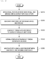
- FIG. 3B is a flowchart illustrating an operation of a wheel assembly for preventing wheel slip.
- the wheel assembly 100 rotates the main wheel 112 in one direction by means of the driving motor and the gear in a state in which the main wheel 112 and the ground are in contact with each other (S310) to generate a grip force between the main wheel 112 and the ground (S320).
- the grip force generated between the main wheel 112 and the ground refers to a horizontal force like a grip force (a frictional force) between the main wheel 112 and the ground.
- the wheel assembly 100 generates a hinge torque with respect to the center of the first hinge axis 115 of the first hinge unit 130 by the grip force generated between the main wheel 112 and the ground.
- the hinge torque refers to a vertical force formed by the grip force and the vertical force refers to a force generated by the horizontal force of step S320.
- the normal force is increased by the hinge torque generated in the first hinge unit 130 (S340) .
- the normal force refers to a force formed in the main wheel 112 by the vertical force in step S330.
- the wheel assembly 100 allows the mobile robot 10 to travel in a state in which the grip force (frictional force) between the main wheel 112 and the ground is increased by the increased normal force (S350).
- the grip force is increased by the increased normal force and the grip force and the normal force are increased with each other until the magnitude of the grip force is equal to or larger than the traveling resistance.
- the grip force between the main wheel 112 and the ground is equal to or larger than the traveling resistance, the wheel assembly 100 moves without causing wheel slip.
- FIGS. 3A and 3B it is described that the steps are sequentially executed, the present disclosure is not necessarily limited thereto. In other words, the steps described in FIGS. 3A and 3B may be modified to be executed or one or more steps may be executed in parallel so that FIGS. 3A and 3B are not limited to a time-sequential order.
- FIG. 4 is a cross-sectional view for explaining a wheel assembly including a plurality of hinge units and a mobile robot according to an exemplary embodiment of the present disclosure.
- the first hinge unit 130 and the second hinge unit 170 are installed in positions with the same height.
- the first hinge unit 130 includes the first hinge axis 115 and the first hinge axis mounting unit 122.
- a hinge torque is generated in a direction opposite to the one rotation direction and the normal force is generated by the hinge torque.
- the first hinge unit 130 is installed in a position with a predetermined distance from a center of the rotary axis of the main wheel 112 and installed at a height between the center of the rotary axis of the main wheel 112 and the ground.
- the grip force between the main wheel 112 and the ground is increased and in the first hinge unit 130, the grip force between the main wheel 112 and the ground is increased by a normal force increased while a hinge torque is generated to the first hinge axis 115 in a direction opposite to the one rotation direction.
- the second hinge unit 170 includes a second hinge axis 152 and a second hinge axis mounting unit 142.
- a hinge torque is generated in a direction opposite to the other rotation direction and the normal force is generated by the hinge torque.
- FIG. 5 is an exemplary view illustrating an operation of a plurality of hinge units during the movement in a wheel assembly according to an exemplary embodiment of the present disclosure.
- FIG. 5(a) illustrates a wheel assembly 100 in a state in which the mobile robot 10 is stopped.
- a hinge torque is generated in a direction opposite to the rotation direction of the main wheel 112 and thus the grip force when the mobile robot 10 travels in the first movement direction may be increased.
- FIGS. 6A and 6B are exploded views illustrating an assembling structure of a wheel assembly including a plurality of hinge units according to an exemplary embodiment of the present disclosure.
- a wheel assembly 100 includes a wheel gear box assembly 110, a wheel lower cover 120, a wheel upper cover 140, a hinge shaft 150, and a sensor 180.
- the description of the wheel gear box assembly 110 and the wheel lower cover 120 of the wheel assembly 100 overlaps the description of FIG. 1 so that a detailed description thereof will be omitted.
- the wheel lower cover 120 is a component which is coupled to a lower surface of the wheel upper cover 140 of FIG. 6 and for the purpose of description of an internal configuration and a coupling structure of the wheel assembly 100, the illustration of the wheel lower cover 120 will be omitted in FIG. 6 .
- the wheel upper cover 140 is coupled to the wheel gear box assembly 110 to protect the upper portion.
- the wheel upper cover 140 is coupled to the wheel lower cover 120 to form a predetermined accommodation space.
- the wheel upper cover 140 includes a second hinge axis mounting unit 152 which is coupled to the second hinge axis 152, at the other side end.
- the second hinge axis mounting unit 142 is coupled to the second hinge axis 152 so as to rotate the second hinge axis 152 while fixing the second hinge axis 152.
- the hinge shaft 150 has a structure which supports the first hinge unit 130 and the second hinge unit 170 and adjusts a rotation radius.
- the hinge shaft 150 may be implemented to support an inner surface of the wheel upper cover 140.
- One side end of the hinge shaft 150 is coupled to the first hinge axis 115 of the wheel gear box assembly 110 and the second hinge axis 152 is equipped at the other side end.
- the wheel gear box assembly 110 may rotate by means of the second hinge axis 152 equipped at the other side end of the hinge shaft 150.
- the hinge shaft 150 includes a hinge coupling hole at one side end and a second hinge axis 152 parallel to the first hinge axis at the other side end.
- the hinge coupling hole of the hinge shaft 150 is coupled to one side end of the first hinge axis 115 formed in the gear box 114.
- the second hinge axis 152 of the hinge shaft 150 is installed in a position with a height different from the first hinge axis 115 with respect to the ground.
- the second hinge axis 152 is installed such that the center of the second hinge axis 152 is located to be lower than the center of the first hinge axis 115 with respect to the ground.
- the second hinge axis 152 may be formed in a position where the height of the second hinge axis 152 is lower than the height between the ground and the first hinge axis 115 by 1 mm or more.
- the second hinge unit 170 includes the second hinge axis 152 and the second hinge axis mounting unit 142.
- a hinge torque is generated in a direction opposite to the other rotation direction and the normal force is generated by the hinge torque.
- FIG. 6A(a) illustrates a wheel assembly 100
- FIG. 6A (b) illustrates an exploded view of the wheel assembly 100
- the first hinge axis 115 formed in the gear box 114 is coupled to the hinge coupling hole equipped at one side end of the hinge shaft 150 and is coupled to the first hinge axis mounting unit 122 in the coupled state.
- the first hinge axis 115 is not coupled to the first hinge axis mounting unit 122, but may be coupled only to the hinge coupling hole.
- FIG. 6B(a) illustrates a wheel assembly 100 and FIG. 6B(b) illustrates an exploded view of the wheel assembly 100.
- the second hinge axis 152 formed at the other end of the hinge shaft 150 may be coupled to the second hinge axis mounting unit 142 equipped in the wheel upper cover 140.
- the sensor 180 senses a state in which the main wheel 112 rotates with respect to the main body of the mobile robot 10 to be lowered.
- the sensor 180 may sense the state of the wheel gear box assembly 110 which is lowered as the second hinge axis 152 rotates by the hinge torque generated in the second hinge unit 170.
- a controller determines that the mobile robot cannot be operated and shuts down the power supplied to the driving motor 116 to stop the operation of the driving motor 116.
- Such an inoperable state of the mobile robot may be a state in which a user lifts and holds the mobile robot or a state in which the mobile is stuck in a high threshold over which the mobile robot cannot pass.
- the sensor 180 may be a contact type sensor or a non-contact type sensor. However, in the exemplary embodiment, the sensor 180 is implemented as a contact type sensor which senses when an object is in contact with a contact unit, like a micro switch.
- FIG. 7 is an exploded view illustrating an assembling structure of a wheel gear box assembly of a wheel assembly according to an exemplary embodiment of the present disclosure.
- a wheel gear box assembly 110 includes a main wheel 112, a gear box 114, and a driving motor 116.
- the main wheel 112 refers to a wheel which rotates to travel the mobile robot 10.
- the main wheel 112 is gripped on the traveling surface (floor) of the mobile robot 10 and is driven by the driving motor 116 to travel the mobile robot 10.
- the main wheel 112 is coupled to a rotary axis of a driven gear included in the gear box 114 to rotate as one unit with the driven gear.
- the main wheel 112 is fixed to the gear box 114 to rotate together with the gear box 114 by the rotation of the first hinge axis 115 equipped in the gear box 114.
- the grip force of the main wheel 112 with the ground may be increased by the rotation of the first hinge axis 115.
- the gear box 114 may include a driving gear which is driven by the driving motor 116 and a driven gear which is driven by the driving gear.
- the driving gear of the gear box 114 is coupled to a rotary axis of the driving motor 116 to be driven by the driving motor 170 and the main wheel 112 is coupled to a rotary axis of the driven gear.
- a transmission gear (not illustrated) which transmits a driving force of the driving gear to the driven gear may be further provided between the driving gear and the driven gear.
- a reduction gear having the configuration as described above transmits the driving force of the driving motor 116 to the main wheel 112.
- the gear box 114 includes a first hinge axis formed to be parallel to the rotary axis of the driven gear at one side end.
- the first hinge axis 115 of the gear box 114 is coupled to a first hinge axis mounting unit 122 equipped in the wheel lower cover 120 to form the first hinge unit 130 which improves the grip force of the main wheel 112.
- the first hinge axis 115 is not coupled to the first hinge axis mounting unit 122, but may be coupled only to the hinge coupling hole at one side end of the hinge shaft 150 to form a first hinge unit 130.
- the driving motor 116 is coupled to the gear box 114 to perform an operation of generating a driving force to rotate the main wheel 112. Even though in the present exemplary embodiment, it is illustrated that the driving motor 116 which supplies a driving force for driving the main wheel 112 is accommodated in the wheel lower cover 120 and the wheel upper cover 140 to be modulated together with the wheel assembly 100 for modulation of the wheel assembly 100, the exemplary embodiment is not necessarily limited thereto.
- the driving motor 116 is not an essential component of the wheel assembly 100 according to the present disclosure. As long as the driving gear is coupled to the driving axis of the driving motor 116, an installation position of the driving motor 116 and a coupling structure with the wheel assembly 100 may vary in various forms.
- the main wheel 112 is coupled to one side end of the gear box 114 and the driving motor 116 is coupled to the other side end.
- a driving gear axis of the gear box 114 is connected to the driving motor 116 to be supplied with the driving force.
- a driven gear axis of the gear box 114 is coupled to the center of the main wheel 112 to rotate in a predetermined direction of the main wheel 112.
- FIG. 8 is a view illustrating a connecting structure of an elastic member of a wheel assembly according to an exemplary embodiment of the present disclosure.
- the wheel assembly 100 may further include an elastic member 160 for quick restoration.
- the elastic member 160 may be a spring, but is not necessarily limited thereto so that the elastic member may be implemented with various configurations having elasticity.
- the elastic member 160 is connected between a first fixing unit 162 equipped in the gear box 114 and a second fixing unit 164 equipped in the wheel upper cover 140.
- the elastic member 160 may restore the gear box 114 of the wheel gear box assembly 110 which rotates by the hinge torque generated in the second hinge unit 170 using an elastic force.
- the first fixing unit 162 is equipped on an upper surface of the gear box 114, it is not necessarily limited thereto. Therefore, as long as the fixing unit 162 can be connected to the second fixing unit 162 by means of the elastic member 160, the first fixing unit may be equipped in the other position of the gear box 114.
- FIG. 9 is a view illustrating a structure of a wheel upper cover for adjusting a rotation angle of a plurality of hinge units according to an exemplary embodiment of the present disclosure.
- the wheel assembly 100 rotates by the first hinge unit 130 or the second hinge unit 170 to improve the grip force.
- the wheel assembly 100 includes a first support unit 144 in the wheel upper cover 140 to limit a rotation angle range when the wheel assembly 100 rotates by the hinge torque generated in the first hinge unit 130.
- the first support unit 144 is in contact with a part of the wheel gear box assembly 110 rotated by the first hinge unit 130 to limit the rotation angle range.
- the part of the wheel gear box assembly 110 refers to one side portion of the gear box 114.
- the wheel assembly 100 includes a second support unit 146 in the wheel upper cover 140 to limit a rotation angle range when the wheel assembly 100 rotates by the hinge torque generated in the second hinge unit 170.
- the second support unit 146 is in contact with a part of the hinge shaft 150 rotated by the second hinge unit 170 to limit the rotation angle range.
- the part of the hinge shaft 150 refers to a part of the main body of the hinge shaft 150 which is adjacent to the hinge coupling hole.
- FIG. 10 is an exploded view illustrating a wheel assembly with a multiple hinge structure including a plurality of hinge shafts according to an exemplary embodiment of the present disclosure.
- the wheel assembly 100 has a configuration including a plurality of hinge shafts 1110 and 1120.
- FIG. 10 illustrates a plurality of hinge shafts 1110 and 1120 including an additional hinge shaft which is coupled to the hinge shaft 150 in the wheel assembly 100 illustrated in FIG. 6A(b) .
- FIG. 10(a) illustrates a wheel assembly 100 in which two hinge shafts 1110 are added
- FIG. 10(b) illustrates a wheel assembly 100 in which three hinge shafts 1120 are added.
- the additional hinge shaft includes a third hinge axis parallel to the first hinge axis 115 provided at one side end and a hinge coupling hole at the other side end.
- FIGS. 11A and 11B are views illustrating a mobile robot to which a wheel assembly for preventing wheel slip according to an exemplary embodiment of the present disclosure is applied.
- FIG. 11A(a) illustrates a perspective view of a mobile robot 10
- FIG. 11A(b) illustrates a side view of the mobile robot 10.
- FIG. 11B illustrates a bottom perspective view of the mobile robot 10.
- the mobile robot 10 performs the cleaning while moving a floor to be cleaned.
- the mobile robot 10 may be a robot which performs suction type or wet type cleaning.
- the mobile robot 10 performs the cleaning while moving on a ground (a cleaning floor) by rotating at least one wheel and a rotary kit equipped in the main body.
- the mobile robot 10 includes a wheel assembly 100, a main body housing 300, and a rotating assembly 400.
- the main body housing 300 is a housing which defines an outer circumference surface of the mobile robot 10 and is configured by an upper housing 310 and a lower housing 320.
- the main body housing 30 may include a body which forms a skeleton such as a support in the mobile robot 10.
- the main body housing 300 may be a concept including both the upper housing 310 and the lower housing 320, but is not necessarily limited thereto and may be a concept that a protective cover is coupled to the lower housing 320.
- the wheel assembly 100 is coupled to the main body housing 300 and generates a momentum to move the mobile robot 10.
- the wheel assembly 100 includes at least one wheel and a wheel driving motor which drives the wheel.
- the wheel assembly 100 may be implemented as a module type which is detachable from the lower housing 320 or independently separated from the lower housing.
- At least one wheel which is included in the wheel assembly 100 is supplied with a driving force of the driving motor to rotate.
- the wheel driving motor is controlled by a control circuit to be driven.
- At least one wheel may be equipped at left and right sides of the lower housing 320 and for the purpose of independent driving of each wheel 100a and 100b, a wheel driving motor may be individually connected to each of the wheels 100a and 100b.
- the mobile robot 10 may move to front, back, left, and right or rotate by at least one wheel included in the wheel assembly 100.
- the wheel of the wheel assembly 100 is actively driven and allows the mobile robot 10 to travel so that the wheel may be referred to as a main wheel.
- the wheel assembly 100 may further include a main wheel encoder (not illustrated) which detects the rotation in accordance with substantial driving of the wheel. Further, the wheel assembly 100 may further include a main wheel sensor (not illustrated) which detects the rotation of the wheel or detects a current applied to the wheel driving motor.
- the control circuit which controls the driving of the wheel assembly 100 may drive the wheel by the control of the wheel driving motor.
- the control circuit may be provided in the wheel assembly or may be implemented to allow the main processor of the mobile robot to perform the function.
- the control circuit may determine whether the main wheel is properly driven in accordance with the instruction from the control circuit with a signal encoded by main wheel encoder from the main wheel sensor and/or a signal acquired from the main wheel sensor as inputs. Further, when the signal detected by the main wheel sensor exceeds a reference value, that is, when the over current is applied to the driving motor, the control circuit may transmit a control signal which stops the traveling to prevent the damage of the circuit or applies a reverse bias to avoid a dangerous situation, to the wheel driving motor.
- an auxiliary wheel 200 may be equipped in a position apart from the wheel assembly 100.
- the auxiliary wheel 200 is equipped in a position in the lower housing 320 different from at least one wheel 100a and 100b.
- the auxiliary wheel 200 may be implemented by a passive auxiliary wheel and an active auxiliary wheel.
- the active auxiliary wheel is driven by a driving force, but the passive auxiliary wheel refers to a wheel which slides as the mobile robot moves by the rotation of the wheels 100a and 100b, without using a driving force.
- the auxiliary wheel 200 supports the mobile robot 10 together with at least one wheel 100a and 100b and assists the driving of the mobile robot 10 by at least one wheel 100a and 100b.
- an auxiliary wheel encoder (not illustrated) which encodes the rotation of the auxiliary wheel 200 and an auxiliary wheel sensor (not illustrated) which senses the rotation of the auxiliary wheel 200 may be further included.
- a rotating assembly 400 is coupled with the main body housing 300 and removes foreign materials on the floor as the mobile robot 10 moves.
- the rotating assembly 400 may be implemented as a module which is separable to be independently detachable from a bottom surface of the main body housing.
- the rotating assembly 400 may be implemented to include a brush or a rotation roller having a wet structure and may also be implemented only by an air inlet which sucks foreign materials on the floor depending on the exemplary embodiment.
- the mobile robot may further include a main processor, a memory, and a power supply.
- the main processor is included in the mobile robot and controls active modules which are actively driven, to be driven, diagnoses a currently traveling situation, and generates an instruction to perform an appropriate operation in accordance with the diagnosed situation to transmit the instruction to a necessary module.
- Modules which are actively driven such as a wheel assembly module or a rotating assembly may include individual sub processors.
- the sub processor may be implemented to perform an operation in accordance with the instruction of the main processor.
- the main processor When there is no sub processor, the main processor generates a driving signal to drive various modules, instead of the sub processor, to transmit the driving signal to the corresponding module.
- the memory may store software necessary to drive the mobile robot cleaner or store traveling information (map information or traveling distance information) generated in accordance with the traveling.
- the power supply supplies a power to drive the mobile robot.
- the mobile robot may further include a communication module. In order to allow the user to remotely control the mobile robot, a communication module needs to be included in the mobile robot, which allows the remote control.
- the main processor or another sub processor may determine the current traveling situation using signals from sensors which sense a state of objects to be driven, such as a signal sensed by the driven modules and the wheel assembly, a signal sensed by the auxiliary wheel, or a signal sensed in association with the rotation of the rotary roller.
- sensors which sense a state of objects to be driven such as a signal sensed by the driven modules and the wheel assembly, a signal sensed by the auxiliary wheel, or a signal sensed in association with the rotation of the rotary roller.
- the main processor or the sub processor a control circuit for each module
- This situation may be generated when the rotation member deviates from the rotary roller or the rotation member gets tangled on the traveling floor.
- a height of the mobile robot and the floor may be consistently lower than a predetermined reference value or a height before being deviated.
- a predetermined reference value or a height before being deviated.
- the rotation of the rotary roller may be disturbed.
- a height from the floor may be low, but the deviation for the height may be large due to the nature of the carpet.
- the main processor or the sub processor may determine whether the current situation is caused by the deviation of the rotation member or is generated in a traveling area such as a carpet, by the operation (calculation of a standard deviation) of the height value.
- the main processor or the sub processor may determine that the rotary roller idly rotates. This may mainly happen in a situation in which almost water is ran out in the rotary roller or the main wheel is difficult to rotate.
- FIG. 12 is a view illustrating a connecting structure of an elastic member of a wheel assembly according to another exemplary embodiment of the present disclosure.
- a wheel assembly 100 may further include at least one elastic member 1200 and 1210.
- the wheel assembly 100 may further include a first elastic member 1200 and a second elastic member 1210 for quick restoration.
- the first elastic member 1200 and the second elastic member 1210 may be springs, but are not necessarily limited thereto so that the elastic member may be implemented with various configurations having elasticity.
- the first elastic member 1200 is connected between a first elastic fixing unit 1202 equipped in the gear box 114 and a second elastic fixing unit 1204 equipped in the wheel upper cover 140.
- the second elastic member 1210 is connected between a third elastic fixing unit 1212 equipped in the gear box 114 and a fourth elastic fixing unit 1214 equipped in the wheel upper cover 140.
- the first elastic member 1200 and the second elastic member 1210 may restore the gear box 114 of the wheel gear box assembly 110 which rotates by the hinge torque generated in the second hinge unit 170 using an elastic force.
Landscapes
- Engineering & Computer Science (AREA)
- Mechanical Engineering (AREA)
- Robotics (AREA)
- Manipulator (AREA)
Abstract
Description
- This application claims priority to and the benefit of Korean Patent Application No.
10-2020-0031557 - The present disclosure relates to a wheel assembly which applies a hinge structure to prevent wheel slip and a mobile robot using the same.
- The contents described in this section merely provide background information on the exemplary embodiment of the present disclosure, but do not constitute the related art.
- A mobile robot is a robot which performs a specific task while traveling by itself or traveling under external control and includes a cleaning robot and a surveillance robot depending on the type of tasks to be performed. Such a mobile robot generally has a function of performing ordered tasks, such as cleaning or surveillance, by itself.
- For example, a mobile robot for cleaning sucks dusts or foreign materials while moving a predetermined cleaning zone such as home or offices by itself. To this end, the mobile robot is configured by a wheel assembly which moves the mobile robot, a plurality of sensing sensors which senses obstacles to allow the mobile robot to move without colliding with various obstacles in the cleaning zone, a battery which supplies power, and a microprocessor which controls the overall device, as well as configurations of a general vacuum cleaner which sucks dust or foreign materials.
- The wheel assembly which allows the mobile robot to travel includes a wheel and a motive power source such as a driving motor which supplies a driving force to the wheel. The wheel rotates by the driving force supplied from the motive power source to allow the mobile robot to travel. However, generally, the wheel is configured to rotate while being fixed to a robot body of the mobile robot. However, the mobile robot may travel not only on a flat traveling surface, but also on an uneven traveling surface such as bumpy traveling surface or pass through an obstacle such as a door sill, or travel on a slippery traveling surface.
- There is a problem in that when a grip force of the wheel of the mobile robot is smaller than a traveling resistance or the traveling resistance is larger than a grip force, wheel slip may be caused. Further, when the mobile robot travels on the bumpy traveling surface, if the traveling surface is uneven so that only one wheel is gripped onto the traveling surface, but the other wheel is located in a concavely dented portion not to be gripped on the traveling surface, the mobile robot may continuously rotate in the same position with the wheel which is not gripped onto the traveling surface as an axis. That is, there may be a problem in that the mobile robot continuously spins without moving forward.
- Further, when the mobile robot travels in an environment (for example, on the carpet) in which the resistance for the traveling is severe, the mobile robot may not normally travel due to the slip phenomenon of the wheel. That is, when the mobile robot travels in an environment having a high traveling resistance, the moving speeds and moving distances at the time of the moving forward and moving backward may be different or the slip phenomenon of the wheel may occur. In this case, it is difficult to control the traveling of the mobile robot and problems such as the risk of safety accidents and irregularity of the cleaning performance may be caused.
- A main object of the present disclosure is to provide a wheel assembly structure which applies at least one hinge unit to a wheel assembly structure which drives a main wheel to prevent wheel slip which increases a normal force and a grip force and a mobile robot using the same.
- According to an aspect of the present disclosure, in order to achieve the above-mentioned object, a wheel assembly of a mobile robot includes a wheel gear box assembly which includes a main wheel to move a mobile robot, a driving motor and a gear which rotate the main wheel and generates a hinge torque to a first hinge axis equipped at one side by the rotation of the main wheel to be rotatable within a predetermined range; a hinge shaft which has one side end coupled to the first hinge axis of the wheel gear box assembly and rotates the wheel gear box assembly by means of a second hinge axis equipped at the other side end; and a wheel upper cover which is coupled to the wheel gear box assembly to protect an upper portion and includes a second hinge axis mounting unit formed at the other side end to be coupled to the second hinge axis.
- According to another aspect of the present disclosure, In order to achieve the above-described objects, a mobile robot includes a main body housing which defines an outer circumference surface of the mobile robot, a wheel assembly which includes a wheel gear box assembly which includes a main wheel to move a mobile robot, a driving motor and a gear which rotate the main wheel and generates a hinge torque to a first hinge axis equipped at one side by the rotation of the main wheel to be rotatable within a predetermined range; a hinge shaft which has one side end coupled to the first hinge axis of the wheel gear box assembly and rotates the wheel gear box assembly by means of a second hinge axis equipped at the other side end, and a wheel upper cover which is coupled to the wheel gear box assembly to protect an upper portion and includes a second hinge axis mounting unit formed at the other side end to be coupled to the second hinge axis, and is coupled to the main body housing; a rotating assembly which includes a rotary roller which rotates toward a floor to be cleaned and is provided to be independently detachable and a rotation member formed on a surface of the rotary roller and removes foreign materials on the floor by means of the rotation of the rotary roller; and a control circuit which controls the operations of the wheel assembly and the rotating assembly.
- As described above, according to the present disclosure, when the mobile robot travels in an environment (for example, on the carpet) in which a resistance for robot traveling is severe, the wheel slip phenomenon may be prevented. Further, according to the present disclosure, the grip force is improved to increase the traveling performances of moving forward and backward to the same level.
- Further, according to the present disclosure, at least one hinge unit is applied to the wheel assembly to enable stable traveling even in an environment in which the traveling resistance is severe.
-
-
FIG. 1 is a cross-sectional view of a structure of a wheel assembly according to an exemplary embodiment of the present disclosure; -
FIG. 2 is a cross-sectional view of a mobile robot for explaining a position of a first hinge unit between an auxiliary wheel and a wheel assembly according to an exemplary embodiment of the present disclosure; -
FIGS. 3A and3B are views for explaining an operating method of a wheel assembly for preventing wheel slip according to an exemplary embodiment of the present disclosure; -
FIG. 4 is a cross-sectional view for explaining a wheel assembly including a plurality of hinge units and a mobile robot according to an exemplary embodiment of the present disclosure; -
FIG. 5 is an exemplary view illustrating an operation of a plurality of hinge units during the movement in a wheel assembly according to an exemplary embodiment of the present disclosure; -
FIGS. 6A and 6B are exploded views illustrating an assembling structure of a wheel assembly including a plurality of hinge units according to an exemplary embodiment of the present disclosure; -
FIG. 7 is an exploded view illustrating an assembling structure of a wheel gear box assembly of a wheel assembly according to an exemplary embodiment of the present disclosure; -
FIG. 8 is a view illustrating a connecting structure of an elastic member of a wheel assembly according to an exemplary embodiment of the present disclosure; -
FIG. 9 is a view illustrating a structure of a wheel upper cover for adjusting a rotation angle of a plurality of hinge units according to an exemplary embodiment of the present disclosure; -
FIG. 10 is an exploded view illustrating a wheel assembly with a multiple hinge structure including a plurality of hinge shafts according to an exemplary embodiment of the present disclosure; -
FIGS. 11A and11B are views illustrating a mobile robot to which a wheel assembly for preventing wheel slip according to an exemplary embodiment of the present disclosure is applied; and -
FIG. 12 is a view illustrating a connecting structure of an elastic member of a wheel assembly according to another exemplary embodiment of the present disclosure. - Hereinafter, exemplary embodiments of the present disclosure will be described in detail with reference to the accompanying drawings. In the description of the present disclosure, if it is considered that the specific description of related known configuration or function may cloud the gist of the present disclosure, the detailed description will be omitted. Further, hereinafter, exemplary embodiments of the present disclosure will be described. However, it should be understood that the technical spirit of the present disclosure is not restricted or limited to the specific embodiments, but may be changed or modified in various ways by those skilled in the art to be carried out. Hereinafter, a wheel assembly structure for preventing wheel slip proposed by the present disclosure and a mobile robot using the same will be described in detail with reference to the drawings.
- The wheel assembly of the mobile robot according to the present disclosure may be installed in various mobile robots which perform a specific task while traveling upon the self-control or the external control, to be operated. In the following description, it is assumed that the wheel assembly of the mobile robot according to the present disclosure is installed in a cleaning mobile robot.
-
FIG. 1 is a cross-sectional view of a structure of a wheel assembly according to an exemplary embodiment of the present disclosure. - The
wheel assembly 100 according to the present disclosure includes a wheelgear box assembly 110 and a wheellower cover 120. Thewheel assembly 100 ofFIG. 1 is an example so that all blocks illustrated inFIG. 1 are not essential components and in another exemplary embodiment, some blocks included in thewheel assembly 100 may be added, modified, or omitted. Thewheel assembly 100 is mounted in a main body of themobile robot 10 to perform an operation to control the traveling to move themobile robot 10. - The wheel
gear box assembly 110 includes amain wheel 112 which moves themobile robot 10, and agear box 114 and adriving motor 116 which rotate themain wheel 112. Further, the wheelgear box assembly 110 includes afirst hinge axis 115 and generates a hinge toque to thefirst hinge axis 115 equipped at one side by the rotation of themain wheel 112 to be rotatable within a predetermined range. - The
main wheel 112 refers to a wheel which rotates to travel themobile robot 10. When thewheel assembly 100 is mounted on the main body of themobile robot 10, themain wheel 112 is gripped on the traveling surface (ground) of themobile robot 10 and is driven by the drivingmotor 116 to travel themobile robot 10. - The
main wheel 112 is coupled to a rotary axis of a driven gear included in thegear box 114 to rotate as one unit with the driven gear. - The
main wheel 112 is fixed to thegear box 114 to rotate together with thegear box 114 by the rotation of thefirst hinge axis 115 equipped in thegear box 114. The grip force of themain wheel 112 with the ground may be increased by the rotation of thefirst hinge axis 115. - The
gear box 114 may include a driving gear which is driven by thedriving motor 116 and a driven gear which is driven by the driving gear. - The driving gear of the
gear box 114 is coupled to a rotary axis of thedriving motor 116 to be driven by the driving motor 170 -> 116 and themain wheel 112 is coupled to a rotary axis of the driven gear. A transmission gear (not illustrated) which transmits a driving force of the driving gear to the driven gear may be further provided between the driving gear and the driven gear. A reduction gear having the configuration as described above transmits the driving force of the drivingmotor 116 to themain wheel 112. - The
gear box 114 includes afirst hinge axis 115 formed to be parallel to the rotary axis of the driven gear at one side end. Thefirst hinge axis 115 of thegear box 114 is coupled to a first hingeaxis mounting unit 122 equipped in the wheellower cover 120 to form thefirst hinge unit 130 which improves the grip force of themain wheel 112. - The driving
motor 116 is coupled to thegear box 114 to perform an operation of generating a driving force to rotate themain wheel 112. Even though in the present exemplary embodiment, it is illustrated that the drivingmotor 116 which supplies a driving force for driving themain wheel 112 is accommodated in the wheellower cover 120 and the wheelupper cover 140 to be modulated together with thewheel assembly 100 for modulation of thewheel assembly 100, the exemplary embodiment is not necessarily limited thereto. For example, the drivingmotor 116 is not an essential component of thewheel assembly 100 according to the present disclosure. As long as the driving gear is coupled to the driving axis of the drivingmotor 116, an installation position of the drivingmotor 116 and a coupling structure with thewheel assembly 100 may vary in various forms. - A coupling structure between components included in the wheel
gear box assembly 110 will be described with reference toFIG. 7 . - The wheel
lower cover 120 is coupled to the wheelgear box assembly 110 to protect the lower portion. The wheellower cover 120 is coupled to the wheelupper cover 140 to form a predetermined accommodation space, but is not necessarily limited thereto. Therefore, when the upper portion is open, the wheelupper cover 140 may be omitted. - The wheel
lower cover 120 includes a first hingeaxis mounting unit 122 which is coupled to thefirst hinge axis 115, at one side end. The first hingeaxis mounting unit 122 is coupled to thefirst hinge axis 115 so as to rotate thefirst hinge axis 115 while fixing thefirst hinge axis 115. - The
first hinge unit 130 includes thefirst hinge axis 115 and the first hingeaxis mounting unit 122. In the meantime, when the wheellower cover 120 is omitted, as illustrated inFIGS. 6A and 6B , thefirst hinge unit 130 may include a part of thehinge shaft 150 which is coupled to the wheelupper cover 140. That is, thefirst hinge unit 130 may have a structure in which thehinge shaft 115 is coupled to a hinge coupling hole at one side end of thehinge shaft 150. - When the
main wheel 112 rotates in one direction, in thefirst hinge unit 130, a hinge torque is generated in a direction opposite to one rotation direction and a normal force is generated by the hinge torque. - The
first hinge unit 130 is installed in a position with a predetermined distance from a center of the rotary axis of themain wheel 112 and installed at a height between the center of the rotary axis of themain wheel 112 and the ground. - When the
main wheel 112 rotates in one rotation direction, the grip force between themain wheel 112 and the ground is increased and the grip force between themain wheel 112 and the ground is increased by a normal force increased while a hinge torque is generated in thefirst hinge axis 115 in a direction opposite to the one rotation direction. - The
wheel assembly 100 rotates together with themain wheel 112 and may further include anauxiliary wheel 200 installed in a position with a distance from themain wheel 112 in the main body of themobile robot 10. - The
first hinge unit 130 is installed between an imaginary reference line C connecting the center of theauxiliary wheel 200 and the center of themain wheel 130 and the ground. In thefirst hinge unit 130, a first distance D1 between the center of theauxiliary wheel 200 and the center of thefirst hinge axis 115 may be formed to be longer than a second distance D2 between the center of themain wheel 112 and the center of thefirst hinge axis 115. The first hinge unit 30 is installed in a position in which the sum of the first distance D1 and the second distance D2 is longer than the length of the imaginary reference line C. - Referring to
FIG. 1 , in thewheel assembly 100 according to the exemplary embodiment, thefirst hinge unit 130 is installed in a position in which a distance A is formed to be longer than a distance B. Here, the distance A refers to a distance between the center of thefirst hinge axis 115 and a thread surface on which themain wheel 112 and the ground are in contact with each other and the distance B refers to a distance between the center of thefirst hinge axis 115 and the ground. - Further, when a driving force is equal to or higher than a reference for rotating the
main wheel 112, in thefirst hinge unit 130, a hinge torque is generated to improve the grip force of themain wheel 112. -
FIG. 2 is a cross-sectional view of a mobile robot for explaining a position of a first hinge unit between an auxiliary wheel and a wheel assembly according to an exemplary embodiment of the present disclosure. - In the
wheel assembly 100 according to the present disclosure, when themain wheel 112 rotates in one direction, thefirst hinge unit 130 is installed to be rotatable in a state in which the firstrotary axis 115 is fixed. That is, in thewheel assembly 100, the firstrotary axis 115 may be implemented only to be rotatable but the height thereof is not adjusted. - The
wheel assembly 100 rotates together with themain wheel 112 and may further include anauxiliary wheel 200 installed in a position with a distance from the main wheel in the main body of themobile robot 10. - The
first hinge unit 130 may be installed only to be rotatable in an environment in which the driving resistance of themain wheel 112 and theauxiliary wheel 200 is high. Specifically, thefirst hinge unit 130 cannot move to a direction in which theauxiliary wheel 200 is equipped due to the driving resistance. - Further, a torque is generated in an opposite direction to the rotation direction of the
main wheel 112 so that thefirst hinge unit 130 cannot move in a direction opposite to the direction in which theauxiliary wheel 200 is equipped. Further, thefirst hinge unit 130 is blocked by the ground on the flat ground so that thefirst hinge unit 130 cannot move downwardly. - Further, the
first hinge unit 130 cannot move to the upward direction opposite to the ground. - The
first hinge unit 130 is installed between an imaginary reference line C connecting the center of theauxiliary wheel 200 and the center of themain wheel 130 and the ground. In thefirst hinge unit 130, a first distance D1 between the center of theauxiliary wheel 200 and the center of thefirst hinge axis 115 may be formed to be longer than a second distance D2 between the center of themain wheel 112 and the center of thefirst hinge axis 115. Thefirst hinge unit 130 is installed in a position in which the sum of the first distance D1 and the second distance D2 is longer than the length of the imaginary reference line C. - In the exemplary embodiment, the sum of the first distance D1 and the second distance D2 has a fixed length value and the imaginary reference line C has a value small than the sum of the first distance D1 and the second distance D2.
- In order to upwardly move the
first hinge unit 130, the center of thefirst hinge axis 115 needs to pass a moment when the length of the imaginary reference line C is equal to the sum of the first distance D1 and the second distance D2. However, to this end, the imaginary reference line C needs to be increased and only way to increase the imaginary reference line C is to rotate themain wheel 112 in the other direction. However, the other direction is opposite to the rotation direction (one direction) of themain wheel 112 so that this way cannot be achieved. - Accordingly, the imaginary reference line C cannot be increased and the length of the imaginary reference line C cannot be equal to the sum of the first direction D1 and the second distance D2 so that the
first hinge unit 130 cannot be move to an upward direction which is opposite to the ground.FIGS. 3A and3B are views for explaining an operating method of a wheel assembly for preventing wheel slip according to an exemplary embodiment of the present disclosure. -
FIG. 3A is a view for explaining an operation of increasing a grip force based on a structure of a wheel assembly for preventing wheel slip andFIG. 3B is a flowchart illustrating an operation of a wheel assembly for preventing wheel slip. Referring toFIGS. 3A and3B , thewheel assembly 100 rotates themain wheel 112 in one direction by means of the driving motor and the gear in a state in which themain wheel 112 and the ground are in contact with each other (S310) to generate a grip force between themain wheel 112 and the ground (S320). Here, the grip force generated between themain wheel 112 and the ground refers to a horizontal force like a grip force (a frictional force) between themain wheel 112 and the ground. - The
wheel assembly 100 generates a hinge torque with respect to the center of thefirst hinge axis 115 of thefirst hinge unit 130 by the grip force generated between themain wheel 112 and the ground. Here, the hinge torque refers to a vertical force formed by the grip force and the vertical force refers to a force generated by the horizontal force of step S320. - In the
wheel assembly 100, the normal force is increased by the hinge torque generated in the first hinge unit 130 (S340) . Here, the normal force refers to a force formed in themain wheel 112 by the vertical force in step S330. - The
wheel assembly 100 allows themobile robot 10 to travel in a state in which the grip force (frictional force) between themain wheel 112 and the ground is increased by the increased normal force (S350). - Specifically, in the
wheel assembly 100, the grip force is increased by the increased normal force and the grip force and the normal force are increased with each other until the magnitude of the grip force is equal to or larger than the traveling resistance. Here, when the grip force between themain wheel 112 and the ground is equal to or larger than the traveling resistance, thewheel assembly 100 moves without causing wheel slip. - Even though in
FIGS. 3A and3B , it is described that the steps are sequentially executed, the present disclosure is not necessarily limited thereto. In other words, the steps described inFIGS. 3A and3B may be modified to be executed or one or more steps may be executed in parallel so thatFIGS. 3A and3B are not limited to a time-sequential order. -
FIG. 4 is a cross-sectional view for explaining a wheel assembly including a plurality of hinge units and a mobile robot according to an exemplary embodiment of the present disclosure. - The
first hinge unit 130 and thesecond hinge unit 170 are installed in positions with the same height. - The
first hinge unit 130 includes thefirst hinge axis 115 and the first hingeaxis mounting unit 122. When themain wheel 112 rotates in one direction, in thefirst hinge unit 130, a hinge torque is generated in a direction opposite to the one rotation direction and the normal force is generated by the hinge torque. - The
first hinge unit 130 is installed in a position with a predetermined distance from a center of the rotary axis of themain wheel 112 and installed at a height between the center of the rotary axis of themain wheel 112 and the ground. - When the
main wheel 112 rotates in one rotation direction, the grip force between themain wheel 112 and the ground is increased and in thefirst hinge unit 130, the grip force between themain wheel 112 and the ground is increased by a normal force increased while a hinge torque is generated to thefirst hinge axis 115 in a direction opposite to the one rotation direction. - The
second hinge unit 170 includes a second hinge axis 152 and a second hingeaxis mounting unit 142. When themain wheel 112 rotates in the other direction, in thesecond hinge unit 170, a hinge torque is generated in a direction opposite to the other rotation direction and the normal force is generated by the hinge torque. -
FIG. 5 is an exemplary view illustrating an operation of a plurality of hinge units during the movement in a wheel assembly according to an exemplary embodiment of the present disclosure. -
FIG. 5(a) illustrates awheel assembly 100 in a state in which themobile robot 10 is stopped. - As illustrated in
FIG. 5(b) , when themain wheel 112 rotates to move themobile robot 10 in a first movement direction, in thesecond hinge unit 170, a hinge torque is generated in a direction opposite to the rotation direction of themain wheel 112 and thus the grip force when themobile robot 10 travels in the first movement direction may be increased. - As illustrated in
FIG. 5(c) , when themain wheel 112 rotates to move themobile robot 10 in a second movement direction, in thefirst hinge unit 130, a hinge torque is generated in a direction opposite to the rotation direction of themain wheel 112 and thus the grip force when themobile robot 10 travels in the second movement direction may be increased.FIGS. 6A and 6B are exploded views illustrating an assembling structure of a wheel assembly including a plurality of hinge units according to an exemplary embodiment of the present disclosure. - A
wheel assembly 100 according to an exemplary embodiment includes a wheelgear box assembly 110, a wheellower cover 120, a wheelupper cover 140, ahinge shaft 150, and asensor 180. - The description of the wheel
gear box assembly 110 and the wheellower cover 120 of thewheel assembly 100 overlaps the description ofFIG. 1 so that a detailed description thereof will be omitted. Further, the wheellower cover 120 is a component which is coupled to a lower surface of the wheelupper cover 140 ofFIG. 6 and for the purpose of description of an internal configuration and a coupling structure of thewheel assembly 100, the illustration of the wheellower cover 120 will be omitted inFIG. 6 . - The wheel
upper cover 140 is coupled to the wheelgear box assembly 110 to protect the upper portion. The wheelupper cover 140 is coupled to the wheellower cover 120 to form a predetermined accommodation space. - The wheel
upper cover 140 includes a second hinge axis mounting unit 152 which is coupled to the second hinge axis 152, at the other side end. The second hingeaxis mounting unit 142 is coupled to the second hinge axis 152 so as to rotate the second hinge axis 152 while fixing the second hinge axis 152. - The
hinge shaft 150 has a structure which supports thefirst hinge unit 130 and thesecond hinge unit 170 and adjusts a rotation radius. Thehinge shaft 150 may be implemented to support an inner surface of the wheelupper cover 140. - One side end of the
hinge shaft 150 is coupled to thefirst hinge axis 115 of the wheelgear box assembly 110 and the second hinge axis 152 is equipped at the other side end. The wheelgear box assembly 110 may rotate by means of the second hinge axis 152 equipped at the other side end of thehinge shaft 150. - The
hinge shaft 150 includes a hinge coupling hole at one side end and a second hinge axis 152 parallel to the first hinge axis at the other side end. The hinge coupling hole of thehinge shaft 150 is coupled to one side end of thefirst hinge axis 115 formed in thegear box 114. - The second hinge axis 152 of the
hinge shaft 150 is installed in a position with a height different from thefirst hinge axis 115 with respect to the ground. Specifically, the second hinge axis 152 is installed such that the center of the second hinge axis 152 is located to be lower than the center of thefirst hinge axis 115 with respect to the ground. For example, the second hinge axis 152 may be formed in a position where the height of the second hinge axis 152 is lower than the height between the ground and thefirst hinge axis 115 by 1 mm or more. - The
second hinge unit 170 includes the second hinge axis 152 and the second hingeaxis mounting unit 142. - When the
main wheel 112 rotates in the other direction, in thesecond hinge unit 170, a hinge torque is generated in a direction opposite to the other rotation direction and the normal force is generated by the hinge torque. -
FIG. 6A(a) illustrates awheel assembly 100 andFIG. 6A (b) illustrates an exploded view of thewheel assembly 100. Referring toFIG. 6A(b) , thefirst hinge axis 115 formed in thegear box 114 is coupled to the hinge coupling hole equipped at one side end of thehinge shaft 150 and is coupled to the first hingeaxis mounting unit 122 in the coupled state. In the meantime, when the configuration of the wheellower cover 120 is omitted, thefirst hinge axis 115 is not coupled to the first hingeaxis mounting unit 122, but may be coupled only to the hinge coupling hole. -
FIG. 6B(a) illustrates awheel assembly 100 andFIG. 6B(b) illustrates an exploded view of thewheel assembly 100. Referring toFIG. 6B(b) , the second hinge axis 152 formed at the other end of thehinge shaft 150 may be coupled to the second hingeaxis mounting unit 142 equipped in the wheelupper cover 140. - The
sensor 180 senses a state in which themain wheel 112 rotates with respect to the main body of themobile robot 10 to be lowered. Thesensor 180 may sense the state of the wheelgear box assembly 110 which is lowered as the second hinge axis 152 rotates by the hinge torque generated in thesecond hinge unit 170. - When the
sensor 180 senses that the lowered state of the wheelgear box assembly 110 is out of a predetermined range, a controller determines that the mobile robot cannot be operated and shuts down the power supplied to the drivingmotor 116 to stop the operation of the drivingmotor 116. Such an inoperable state of the mobile robot may be a state in which a user lifts and holds the mobile robot or a state in which the mobile is stuck in a high threshold over which the mobile robot cannot pass. Thesensor 180 may be a contact type sensor or a non-contact type sensor. However, in the exemplary embodiment, thesensor 180 is implemented as a contact type sensor which senses when an object is in contact with a contact unit, like a micro switch. -
FIG. 7 is an exploded view illustrating an assembling structure of a wheel gear box assembly of a wheel assembly according to an exemplary embodiment of the present disclosure. A wheelgear box assembly 110 includes amain wheel 112, agear box 114, and a drivingmotor 116. - The
main wheel 112 refers to a wheel which rotates to travel themobile robot 10. When thewheel assembly 100 is mounted on the main body of themobile robot 10, themain wheel 112 is gripped on the traveling surface (floor) of themobile robot 10 and is driven by the drivingmotor 116 to travel themobile robot 10. - The
main wheel 112 is coupled to a rotary axis of a driven gear included in thegear box 114 to rotate as one unit with the driven gear. - The
main wheel 112 is fixed to thegear box 114 to rotate together with thegear box 114 by the rotation of thefirst hinge axis 115 equipped in thegear box 114. The grip force of themain wheel 112 with the ground may be increased by the rotation of thefirst hinge axis 115. - The
gear box 114 may include a driving gear which is driven by the drivingmotor 116 and a driven gear which is driven by the driving gear. - The driving gear of the
gear box 114 is coupled to a rotary axis of the drivingmotor 116 to be driven by the drivingmotor 170 and themain wheel 112 is coupled to a rotary axis of the driven gear. A transmission gear (not illustrated) which transmits a driving force of the driving gear to the driven gear may be further provided between the driving gear and the driven gear. A reduction gear having the configuration as described above transmits the driving force of the drivingmotor 116 to themain wheel 112. - The
gear box 114 includes a first hinge axis formed to be parallel to the rotary axis of the driven gear at one side end. Thefirst hinge axis 115 of thegear box 114 is coupled to a first hingeaxis mounting unit 122 equipped in the wheellower cover 120 to form thefirst hinge unit 130 which improves the grip force of themain wheel 112. - In the meantime, when the configuration of the wheel
lower cover 120 is omitted, thefirst hinge axis 115 is not coupled to the first hingeaxis mounting unit 122, but may be coupled only to the hinge coupling hole at one side end of thehinge shaft 150 to form afirst hinge unit 130. - The driving
motor 116 is coupled to thegear box 114 to perform an operation of generating a driving force to rotate themain wheel 112. Even though in the present exemplary embodiment, it is illustrated that the drivingmotor 116 which supplies a driving force for driving themain wheel 112 is accommodated in the wheellower cover 120 and the wheelupper cover 140 to be modulated together with thewheel assembly 100 for modulation of thewheel assembly 100, the exemplary embodiment is not necessarily limited thereto. For example, the drivingmotor 116 is not an essential component of thewheel assembly 100 according to the present disclosure. As long as the driving gear is coupled to the driving axis of the drivingmotor 116, an installation position of the drivingmotor 116 and a coupling structure with thewheel assembly 100 may vary in various forms. - Referring to
FIG. 7 , themain wheel 112 is coupled to one side end of thegear box 114 and the drivingmotor 116 is coupled to the other side end. Here, a driving gear axis of thegear box 114 is connected to the drivingmotor 116 to be supplied with the driving force. Further, a driven gear axis of thegear box 114 is coupled to the center of themain wheel 112 to rotate in a predetermined direction of themain wheel 112. -
FIG. 8 is a view illustrating a connecting structure of an elastic member of a wheel assembly according to an exemplary embodiment of the present disclosure. - When the wheel
gear box assembly 110 rotates by thesecond hinge unit 170, thewheel assembly 100 may further include anelastic member 160 for quick restoration. Here, theelastic member 160 may be a spring, but is not necessarily limited thereto so that the elastic member may be implemented with various configurations having elasticity. - Referring to
FIG. 8 , theelastic member 160 is connected between afirst fixing unit 162 equipped in thegear box 114 and asecond fixing unit 164 equipped in the wheelupper cover 140. Theelastic member 160 may restore thegear box 114 of the wheelgear box assembly 110 which rotates by the hinge torque generated in thesecond hinge unit 170 using an elastic force. Here, even though it is illustrated that thefirst fixing unit 162 is equipped on an upper surface of thegear box 114, it is not necessarily limited thereto. Therefore, as long as the fixingunit 162 can be connected to thesecond fixing unit 162 by means of theelastic member 160, the first fixing unit may be equipped in the other position of thegear box 114. -
FIG. 9 is a view illustrating a structure of a wheel upper cover for adjusting a rotation angle of a plurality of hinge units according to an exemplary embodiment of the present disclosure. - Referring to
FIG. 9 , in an environment having a high traveling resistance, thewheel assembly 100 rotates by thefirst hinge unit 130 or thesecond hinge unit 170 to improve the grip force. - The
wheel assembly 100 includes a first support unit 144 in the wheelupper cover 140 to limit a rotation angle range when thewheel assembly 100 rotates by the hinge torque generated in thefirst hinge unit 130. The first support unit 144 is in contact with a part of the wheelgear box assembly 110 rotated by thefirst hinge unit 130 to limit the rotation angle range. Here, the part of the wheelgear box assembly 110 refers to one side portion of thegear box 114. - The
wheel assembly 100 includes asecond support unit 146 in the wheelupper cover 140 to limit a rotation angle range when thewheel assembly 100 rotates by the hinge torque generated in thesecond hinge unit 170. Thesecond support unit 146 is in contact with a part of thehinge shaft 150 rotated by thesecond hinge unit 170 to limit the rotation angle range. Here, the part of thehinge shaft 150 refers to a part of the main body of thehinge shaft 150 which is adjacent to the hinge coupling hole. -
FIG. 10 is an exploded view illustrating a wheel assembly with a multiple hinge structure including a plurality of hinge shafts according to an exemplary embodiment of the present disclosure. - The
wheel assembly 100 has a configuration including a plurality ofhinge shafts -
FIG. 10 illustrates a plurality ofhinge shafts hinge shaft 150 in thewheel assembly 100 illustrated inFIG. 6A(b) .FIG. 10(a) illustrates awheel assembly 100 in which twohinge shafts 1110 are added andFIG. 10(b) illustrates awheel assembly 100 in which threehinge shafts 1120 are added. Here, the additional hinge shaft includes a third hinge axis parallel to thefirst hinge axis 115 provided at one side end and a hinge coupling hole at the other side end. -
FIGS. 11A and11B are views illustrating a mobile robot to which a wheel assembly for preventing wheel slip according to an exemplary embodiment of the present disclosure is applied.FIG. 11A(a) illustrates a perspective view of amobile robot 10 andFIG. 11A(b) illustrates a side view of themobile robot 10. Further,FIG. 11B illustrates a bottom perspective view of themobile robot 10. - The
mobile robot 10 according to an exemplary embodiment of the present disclosure performs the cleaning while moving a floor to be cleaned. Here, themobile robot 10 may be a robot which performs suction type or wet type cleaning. Specifically, themobile robot 10 performs the cleaning while moving on a ground (a cleaning floor) by rotating at least one wheel and a rotary kit equipped in the main body. - The
mobile robot 10 includes awheel assembly 100, amain body housing 300, and arotating assembly 400. - The
main body housing 300 is a housing which defines an outer circumference surface of themobile robot 10 and is configured by anupper housing 310 and alower housing 320. Here, the main body housing 30 may include a body which forms a skeleton such as a support in themobile robot 10. - The
main body housing 300 according to the exemplary embodiment may be a concept including both theupper housing 310 and thelower housing 320, but is not necessarily limited thereto and may be a concept that a protective cover is coupled to thelower housing 320. - The
wheel assembly 100 is coupled to themain body housing 300 and generates a momentum to move themobile robot 10. Thewheel assembly 100 includes at least one wheel and a wheel driving motor which drives the wheel. Thewheel assembly 100 may be implemented as a module type which is detachable from thelower housing 320 or independently separated from the lower housing. - At least one wheel which is included in the
wheel assembly 100 is supplied with a driving force of the driving motor to rotate. Here, the wheel driving motor is controlled by a control circuit to be driven. At least one wheel may be equipped at left and right sides of thelower housing 320 and for the purpose of independent driving of eachwheel wheels mobile robot 10 may move to front, back, left, and right or rotate by at least one wheel included in thewheel assembly 100. The wheel of thewheel assembly 100 is actively driven and allows themobile robot 10 to travel so that the wheel may be referred to as a main wheel. According to another exemplary embodiment of the present disclosure, thewheel assembly 100 may further include a main wheel encoder (not illustrated) which detects the rotation in accordance with substantial driving of the wheel. Further, thewheel assembly 100 may further include a main wheel sensor (not illustrated) which detects the rotation of the wheel or detects a current applied to the wheel driving motor. - The control circuit which controls the driving of the
wheel assembly 100 may drive the wheel by the control of the wheel driving motor. The control circuit may be provided in the wheel assembly or may be implemented to allow the main processor of the mobile robot to perform the function. The control circuit may determine whether the main wheel is properly driven in accordance with the instruction from the control circuit with a signal encoded by main wheel encoder from the main wheel sensor and/or a signal acquired from the main wheel sensor as inputs. Further, when the signal detected by the main wheel sensor exceeds a reference value, that is, when the over current is applied to the driving motor, the control circuit may transmit a control signal which stops the traveling to prevent the damage of the circuit or applies a reverse bias to avoid a dangerous situation, to the wheel driving motor. - According to an exemplary embodiment of the present disclosure, an
auxiliary wheel 200 may be equipped in a position apart from thewheel assembly 100. Theauxiliary wheel 200 is equipped in a position in thelower housing 320 different from at least onewheel auxiliary wheel 200 may be implemented by a passive auxiliary wheel and an active auxiliary wheel. The active auxiliary wheel is driven by a driving force, but the passive auxiliary wheel refers to a wheel which slides as the mobile robot moves by the rotation of thewheels auxiliary wheel 200 supports themobile robot 10 together with at least onewheel mobile robot 10 by at least onewheel auxiliary wheel 200 and an auxiliary wheel sensor (not illustrated) which senses the rotation of theauxiliary wheel 200 may be further included. - A
rotating assembly 400 is coupled with themain body housing 300 and removes foreign materials on the floor as themobile robot 10 moves. Therotating assembly 400 may be implemented as a module which is separable to be independently detachable from a bottom surface of the main body housing. Therotating assembly 400 may be implemented to include a brush or a rotation roller having a wet structure and may also be implemented only by an air inlet which sucks foreign materials on the floor depending on the exemplary embodiment. - Even though not illustrated in
FIGS. 11A and11B , the mobile robot may further include a main processor, a memory, and a power supply. The main processor is included in the mobile robot and controls active modules which are actively driven, to be driven, diagnoses a currently traveling situation, and generates an instruction to perform an appropriate operation in accordance with the diagnosed situation to transmit the instruction to a necessary module. Modules which are actively driven, such as a wheel assembly module or a rotating assembly may include individual sub processors. In this case, the sub processor may be implemented to perform an operation in accordance with the instruction of the main processor. When there is no sub processor, the main processor generates a driving signal to drive various modules, instead of the sub processor, to transmit the driving signal to the corresponding module. The memory may store software necessary to drive the mobile robot cleaner or store traveling information (map information or traveling distance information) generated in accordance with the traveling. The power supply supplies a power to drive the mobile robot. Further, the mobile robot may further include a communication module. In order to allow the user to remotely control the mobile robot, a communication module needs to be included in the mobile robot, which allows the remote control. - According to another exemplary embodiment of the present disclosure, the main processor or another sub processor may determine the current traveling situation using signals from sensors which sense a state of objects to be driven, such as a signal sensed by the driven modules and the wheel assembly, a signal sensed by the auxiliary wheel, or a signal sensed in association with the rotation of the rotary roller. For example, when the wheel of the wheel assembly rotates in a normal range, but the rotary roller does not properly rotate, the main processor or the sub processor (a control circuit for each module) may notice that malfunction with regard to the rotation of the rotary roller is currently generated and generate an escaping instruction to escape from this situation. This situation may be generated when the rotation member deviates from the rotary roller or the rotation member gets tangled on the traveling floor. When the rotation member deviates from the rotary roller, a height of the mobile robot and the floor (which is sensed by a PSD sensor) may be consistently lower than a predetermined reference value or a height before being deviated. In contrast, even in a situation in which the rotation member is prone to sticking such as a carpet, the rotation of the rotary roller may be disturbed. In the case of a floor member which is soft and has a predetermined height, such as a carpet, a height from the floor may be low, but the deviation for the height may be large due to the nature of the carpet. The main processor or the sub processor may determine whether the current situation is caused by the deviation of the rotation member or is generated in a traveling area such as a carpet, by the operation (calculation of a standard deviation) of the height value.
- Further, when the current applied to the circuit to drive the rotary roller is lower than a reference value or when a revolution of the rotary roller is larger than a revolution of the main wheel, or when a movement distance calculated in accordance with the revolution of the rotary roller is larger than a movement distance calculated in accordance with the revolution of the main wheel, the main processor or the sub processor may determine that the rotary roller idly rotates. This may mainly happen in a situation in which almost water is ran out in the rotary roller or the main wheel is difficult to rotate.
-
FIG. 12 is a view illustrating a connecting structure of an elastic member of a wheel assembly according to another exemplary embodiment of the present disclosure. - Referring to
FIG. 12 , awheel assembly 100 according to another exemplary embodiment of the present disclosure may further include at least oneelastic member - When the wheel
gear box assembly 110 rotates by thesecond hinge unit 170, thewheel assembly 100 may further include a firstelastic member 1200 and a secondelastic member 1210 for quick restoration. Here, the firstelastic member 1200 and the secondelastic member 1210 may be springs, but are not necessarily limited thereto so that the elastic member may be implemented with various configurations having elasticity. - Referring to
FIG. 12 , the firstelastic member 1200 is connected between a firstelastic fixing unit 1202 equipped in thegear box 114 and a secondelastic fixing unit 1204 equipped in the wheelupper cover 140. The secondelastic member 1210 is connected between a thirdelastic fixing unit 1212 equipped in thegear box 114 and a fourthelastic fixing unit 1214 equipped in the wheelupper cover 140. - The first
elastic member 1200 and the secondelastic member 1210 may restore thegear box 114 of the wheelgear box assembly 110 which rotates by the hinge torque generated in thesecond hinge unit 170 using an elastic force. - It will be appreciated that various exemplary embodiments of the present disclosure have been described herein for purposes of illustration, and that various modifications and changes may be made by those skilled in the art without departing from the scope and spirit of the present invention. Accordingly, the exemplary embodiments of the present disclosure are not intended to limit but describe the technical spirit of the present invention and the scope of the technical spirit of the present invention is not restricted by the exemplary embodiments. The protective scope of the exemplary embodiment of the present invention should be construed based on the following claims, and all the technical concepts in the equivalent scope thereof should be construed as falling within the scope of the exemplary embodiment of the present invention.
Claims (14)
- A wheel assembly of a mobile robot, comprising:a wheel gear box assembly which includes a main wheel to move a mobile robot, a driving motor and a gear which rotate the main wheel and generates a hinge torque to a first hinge axis equipped at one side by the rotation of the main wheel to be rotatable within a predetermined range;a hinge shaft which has one side end coupled to the first hinge axis of the wheel gear box assembly and rotates the wheel gear box assembly by means of a second hinge axis equipped at the other side end; anda wheel upper cover which is coupled to the wheel gear box assembly to protect an upper portion and includes a second hinge axis mounting unit formed at the other side end to be coupled to the second hinge axis.
- The wheel assembly of a mobile robot according to claim 1, wherein the wheel gear box assembly includes:a driving motor which generates a driving force to rotate the main wheel;a gear box which includes a driving gear which is driven by the driving motor and a driven gear which is driven by the driving gear and includes a first hinge axis formed to be parallel to a rotary axis of the driven gear at one side end; anda main wheel which is coupled to the rotary axis of the driven gear to rotate as one unit with the driven gear and increases a grip force by the rotation of the first hinge axis.
- The wheel assembly of a mobile robot according to claim 2, wherein in a first hinge unit in which the first hinge axis is coupled to a hinge coupling hole at one side end of the hinge shaft, when the main wheel rotates in one direction, the hinge torque is generated in a direction opposite to one rotation direction and a normal force is generated by the hinge torque.
- The wheel assembly of a mobile robot according to claim 3, wherein the first hinge unit is installed in a position with a predetermined distance from a center of the rotary axis of the main wheel and is installed at a height between the center of the rotary axis of the main wheel and a ground.
- The wheel assembly of a mobile robot according to claim 3, wherein when the main wheel is rotatably driven in one rotation direction, in the first hinge unit, a grip force between the main wheel and the ground is increased and the grip force between the main wheel and the ground is increased by the normal force increased while a torque is generated to the first hinge axis in a direction opposite to one rotation direction.
- The wheel assembly of a mobile robot according to claim 3, further comprising:an auxiliary wheel which rotates together with the main wheel and is fixed in a position with a predetermined distance from the main wheel in a main body of the mobile robot,wherein the first hinge unit is installed between an imaginary reference line C connecting a center of the auxiliary wheel and a center of the main wheel and the ground.
- The wheel assembly of a mobile robot according to claim 6, wherein in the first hinge unit, a first distance D1 between the center of the auxiliary wheel and the center of the first hinge axis is longer than a second distance D2 between the center of the main wheel and the center of the first hinge axis, and the first hinge unit is installed in a position in which the sum of the first distance D1 and the second distance D2 is longer than a length of the imaginary reference line C.
- The wheel assembly of a mobile robot according to claim 2, wherein in a second hinge unit in which the second hinge axis is coupled to the second hinge mounting unit, when the main wheel rotates in the other direction, the hinge torque is generated in a direction opposite to the other rotation direction and a normal force is generated by the hinge torque.
- The wheel assembly of a mobile robot according to claim 8, further comprising:at least one elastic member which is connected between a first fixing unit equipped in the gear box and a second fixing unit equipped in the wheel upper cover,wherein at least one elastic member restores the gear box which rotates by the hinge torque generated in the second hinge unit.
- The wheel assembly of a mobile robot according to claim 2, wherein the hinge shaft incudes a hinge coupling hole coupled to one side end of the first hinge axis formed in the gear box at one side end and a second hinge axis parallel to the first hinge axis at the other side end, and the second hinge axis is installed such that the center of the second hinge axis is formed to be lower than the center of the first hinge axis with respect to the ground.
- The wheel assembly of a mobile robot according to claim 2, further comprising:an additional hinge shaft coupled to the hinge shaft,wherein the additional hinge shaft includes a hinge coupling hole at one side end and a third hinge axis located on a straight line with the first hinge axis at the other side end.
- A mobile robot for cleaning, comprising:a main body housing which defines an outer circumference surface of the mobile robot,a wheel assembly which includes a wheel gear box assembly which includes a main wheel to move a mobile robot, a driving motor and a gear which rotate the main wheel and generates a hinge torque to a first hinge axis equipped at one side by the rotation of the main wheel to be rotatable within a predetermined range, a hinge shaft which has one side end coupled to the first hinge axis of the wheel gear box assembly and rotates the wheel gear box assembly by means of a second hinge axis equipped at the other side end; and a wheel upper cover which is coupled to the wheel gear box assembly to protect an upper portion and includes a second hinge axis mounting unit formed at the other side end to be coupled to the second hinge axis, and is coupled to the main body housing;a rotating assembly which includes a rotary roller which rotates toward a floor to be cleaned and is provided to be independently detachable and a rotation member formed on a surface of the rotary roller and removes foreign materials on the floor by means of the rotation of the rotary roller; anda control circuit which controls the operations of the wheel assembly and the rotating assembly.
- The mobile robot according to claim 12, wherein the wheel gear box assembly includes:a driving motor which generates a driving force to rotate the main wheel;a gear box which includes a driving gear which is driven by the driving motor and a driven gear which is driven by the driving gear and includes a first hinge axis formed to be parallel to a rotary axis of the driven gear at one side end; anda main wheel which is coupled to the rotary axis of the driven gear to rotate as one unit with the driven gear and increases a grip force by the rotation of the first hinge axis andin a first hinge unit in which the first hinge axis is coupled to a hinge coupling hole at one side end of the hinge shaft, when the main wheel rotates in one direction, the hinge torque is generated in a direction opposite to one rotation direction and a normal force is generated by the hinge torque.
- The mobile robot according to claim 13, wherein in a second hinge unit in which the second hinge axis is coupled to the second hinge mounting unit, when the main wheel rotates in the other direction, the hinge torque is generated in a direction opposite to the other rotation direction and a normal force is generated by the hinge torque.
Applications Claiming Priority (1)
| Application Number | Priority Date | Filing Date | Title |
|---|---|---|---|
| KR1020200031557A KR102270318B1 (en) | 2020-03-13 | 2020-03-13 | Wheel Assembly Structure for Preventing Wheel Slip and Mobile Robot Using It |
Publications (2)
| Publication Number | Publication Date |
|---|---|
| EP3878339A1 true EP3878339A1 (en) | 2021-09-15 |
| EP3878339B1 EP3878339B1 (en) | 2023-06-28 |
Family
ID=75172990
Family Applications (1)
| Application Number | Title | Priority Date | Filing Date |
|---|---|---|---|
| EP21161986.1A Active EP3878339B1 (en) | 2020-03-13 | 2021-03-11 | Wheel assembly structure for preventing wheel slip and mobile robot using the same |
Country Status (2)
| Country | Link |
|---|---|
| EP (1) | EP3878339B1 (en) |
| KR (1) | KR102270318B1 (en) |
Citations (3)
| Publication number | Priority date | Publication date | Assignee | Title |
|---|---|---|---|---|
| CN105640445A (en) * | 2016-03-01 | 2016-06-08 | 江苏美的清洁电器股份有限公司 | Driving wheel assembly for sweep robot |
| EP3342322A1 (en) * | 2015-11-20 | 2018-07-04 | Samsung Electronics Co., Ltd. | Wheel assembly and robot cleaner having same |
| US20200039307A1 (en) * | 2017-09-01 | 2020-02-06 | Guangdong Bona Robot Co., Ltd. | Mobile mechanism and mobile robot having same, and mobile method |
Family Cites Families (1)
| Publication number | Priority date | Publication date | Assignee | Title |
|---|---|---|---|---|
| KR101311295B1 (en) * | 2011-07-13 | 2013-09-25 | 주식회사 유진로봇 | Wheel assembly for moving robot |
-
2020
- 2020-03-13 KR KR1020200031557A patent/KR102270318B1/en active IP Right Grant
-
2021
- 2021-03-11 EP EP21161986.1A patent/EP3878339B1/en active Active
Patent Citations (3)
| Publication number | Priority date | Publication date | Assignee | Title |
|---|---|---|---|---|
| EP3342322A1 (en) * | 2015-11-20 | 2018-07-04 | Samsung Electronics Co., Ltd. | Wheel assembly and robot cleaner having same |
| CN105640445A (en) * | 2016-03-01 | 2016-06-08 | 江苏美的清洁电器股份有限公司 | Driving wheel assembly for sweep robot |
| US20200039307A1 (en) * | 2017-09-01 | 2020-02-06 | Guangdong Bona Robot Co., Ltd. | Mobile mechanism and mobile robot having same, and mobile method |
Also Published As
| Publication number | Publication date |
|---|---|
| KR102270318B1 (en) | 2021-06-29 |
| EP3878339B1 (en) | 2023-06-28 |
Similar Documents
| Publication | Publication Date | Title |
|---|---|---|
| US7568536B2 (en) | Omni-directional robot cleaner | |
| KR101311295B1 (en) | Wheel assembly for moving robot | |
| US10653283B2 (en) | Self-propelled electronic device and travel method for said self-propelled electronic device | |
| EP2721987B1 (en) | Method of controlling automatic cleaner | |
| KR20080028988A (en) | Robotic cleaning device | |
| US11064858B2 (en) | Robot cleaner and control method thereof | |
| US20050010330A1 (en) | Autonomous machine for docking with a docking station and method for docking | |
| TWI603704B (en) | Robot cleaner | |
| US11083356B2 (en) | Robotic dust collector and self-propelled device | |
| EP3793419B1 (en) | Robotic cleaning device with retractable side brush | |
| EP2886030B1 (en) | Automatic cleaner | |
| WO2017119255A1 (en) | Autonomous traveling body | |
| KR101618130B1 (en) | Robot Cleaner | |
| EP3679848A1 (en) | Self-propelled vacuum cleaner | |
| EP3878339A1 (en) | Wheel assembly structure for preventing wheel slip and mobile robot using the same | |
| JP2014212960A (en) | Vacuum cleaner | |
| JPWO2019087378A1 (en) | Self-propelled vacuum cleaner | |
| TWI687190B (en) | Autonomous cleaner | |
| KR101503601B1 (en) | Robot cleaner | |
| TWI752596B (en) | Robot cleaner | |
| JP2014061764A (en) | Crawler type traveller, and control method thereof | |
| JPWO2004054423A1 (en) | Unmanned vacuum cleaner | |
| KR102373832B1 (en) | Robot Cleaner | |
| JP5761062B2 (en) | Magnetic body moving vehicle and air blowing control method | |
| CN116869436A (en) | Moving wheel mechanism, cleaning robot and cleaning robot system |
Legal Events
| Date | Code | Title | Description |
|---|---|---|---|
| PUAI | Public reference made under article 153(3) epc to a published international application that has entered the european phase |
Free format text: ORIGINAL CODE: 0009012 |
|
| STAA | Information on the status of an ep patent application or granted ep patent |
Free format text: STATUS: THE APPLICATION HAS BEEN PUBLISHED |
|
| STAA | Information on the status of an ep patent application or granted ep patent |
Free format text: STATUS: REQUEST FOR EXAMINATION WAS MADE |
|
| AK | Designated contracting states |
Kind code of ref document: A1 Designated state(s): AL AT BE BG CH CY CZ DE DK EE ES FI FR GB GR HR HU IE IS IT LI LT LU LV MC MK MT NL NO PL PT RO RS SE SI SK SM TR |
|
| 17P | Request for examination filed |
Effective date: 20210902 |
|
| RBV | Designated contracting states (corrected) |
Designated state(s): AL AT BE BG CH CY CZ DE DK EE ES FI FR GB GR HR HU IE IS IT LI LT LU LV MC MK MT NL NO PL PT RO RS SE SI SK SM TR |
|
| GRAP | Despatch of communication of intention to grant a patent |
Free format text: ORIGINAL CODE: EPIDOSNIGR1 |
|
| STAA | Information on the status of an ep patent application or granted ep patent |
Free format text: STATUS: GRANT OF PATENT IS INTENDED |
|
| INTG | Intention to grant announced |
Effective date: 20230221 |
|
| GRAS | Grant fee paid |
Free format text: ORIGINAL CODE: EPIDOSNIGR3 |
|
| GRAA | (expected) grant |
Free format text: ORIGINAL CODE: 0009210 |
|
| STAA | Information on the status of an ep patent application or granted ep patent |
Free format text: STATUS: THE PATENT HAS BEEN GRANTED |
|
| AK | Designated contracting states |
Kind code of ref document: B1 Designated state(s): AL AT BE BG CH CY CZ DE DK EE ES FI FR GB GR HR HU IE IS IT LI LT LU LV MC MK MT NL NO PL PT RO RS SE SI SK SM TR |
|
| REG | Reference to a national code |
Ref country code: CH Ref legal event code: EP |
|
| REG | Reference to a national code |
Ref country code: AT Ref legal event code: REF Ref document number: 1581951 Country of ref document: AT Kind code of ref document: T Effective date: 20230715 |
|
| REG | Reference to a national code |
Ref country code: IE Ref legal event code: FG4D |
|
| REG | Reference to a national code |
Ref country code: DE Ref legal event code: R096 Ref document number: 602021003083 Country of ref document: DE |
|
| REG | Reference to a national code |
Ref country code: LT Ref legal event code: MG9D |
|
| PG25 | Lapsed in a contracting state [announced via postgrant information from national office to epo] |
Ref country code: SE Free format text: LAPSE BECAUSE OF FAILURE TO SUBMIT A TRANSLATION OF THE DESCRIPTION OR TO PAY THE FEE WITHIN THE PRESCRIBED TIME-LIMIT Effective date: 20230628 Ref country code: NO Free format text: LAPSE BECAUSE OF FAILURE TO SUBMIT A TRANSLATION OF THE DESCRIPTION OR TO PAY THE FEE WITHIN THE PRESCRIBED TIME-LIMIT Effective date: 20230928 |
|
| REG | Reference to a national code |
Ref country code: NL Ref legal event code: MP Effective date: 20230628 |
|
| REG | Reference to a national code |
Ref country code: AT Ref legal event code: MK05 Ref document number: 1581951 Country of ref document: AT Kind code of ref document: T Effective date: 20230628 |
|
| PG25 | Lapsed in a contracting state [announced via postgrant information from national office to epo] |
Ref country code: RS Free format text: LAPSE BECAUSE OF FAILURE TO SUBMIT A TRANSLATION OF THE DESCRIPTION OR TO PAY THE FEE WITHIN THE PRESCRIBED TIME-LIMIT Effective date: 20230628 Ref country code: NL Free format text: LAPSE BECAUSE OF FAILURE TO SUBMIT A TRANSLATION OF THE DESCRIPTION OR TO PAY THE FEE WITHIN THE PRESCRIBED TIME-LIMIT Effective date: 20230628 Ref country code: LV Free format text: LAPSE BECAUSE OF FAILURE TO SUBMIT A TRANSLATION OF THE DESCRIPTION OR TO PAY THE FEE WITHIN THE PRESCRIBED TIME-LIMIT Effective date: 20230628 Ref country code: LT Free format text: LAPSE BECAUSE OF FAILURE TO SUBMIT A TRANSLATION OF THE DESCRIPTION OR TO PAY THE FEE WITHIN THE PRESCRIBED TIME-LIMIT Effective date: 20230628 Ref country code: HR Free format text: LAPSE BECAUSE OF FAILURE TO SUBMIT A TRANSLATION OF THE DESCRIPTION OR TO PAY THE FEE WITHIN THE PRESCRIBED TIME-LIMIT Effective date: 20230628 Ref country code: GR Free format text: LAPSE BECAUSE OF FAILURE TO SUBMIT A TRANSLATION OF THE DESCRIPTION OR TO PAY THE FEE WITHIN THE PRESCRIBED TIME-LIMIT Effective date: 20230929 |
|
| PG25 | Lapsed in a contracting state [announced via postgrant information from national office to epo] |
Ref country code: FI Free format text: LAPSE BECAUSE OF FAILURE TO SUBMIT A TRANSLATION OF THE DESCRIPTION OR TO PAY THE FEE WITHIN THE PRESCRIBED TIME-LIMIT Effective date: 20230628 |
|
| PG25 | Lapsed in a contracting state [announced via postgrant information from national office to epo] |
Ref country code: SK Free format text: LAPSE BECAUSE OF FAILURE TO SUBMIT A TRANSLATION OF THE DESCRIPTION OR TO PAY THE FEE WITHIN THE PRESCRIBED TIME-LIMIT Effective date: 20230628 |
|
| PG25 | Lapsed in a contracting state [announced via postgrant information from national office to epo] |
Ref country code: ES Free format text: LAPSE BECAUSE OF FAILURE TO SUBMIT A TRANSLATION OF THE DESCRIPTION OR TO PAY THE FEE WITHIN THE PRESCRIBED TIME-LIMIT Effective date: 20230628 |
|
| PG25 | Lapsed in a contracting state [announced via postgrant information from national office to epo] |
Ref country code: IS Free format text: LAPSE BECAUSE OF FAILURE TO SUBMIT A TRANSLATION OF THE DESCRIPTION OR TO PAY THE FEE WITHIN THE PRESCRIBED TIME-LIMIT Effective date: 20231028 |
|
| PG25 | Lapsed in a contracting state [announced via postgrant information from national office to epo] |
Ref country code: SM Free format text: LAPSE BECAUSE OF FAILURE TO SUBMIT A TRANSLATION OF THE DESCRIPTION OR TO PAY THE FEE WITHIN THE PRESCRIBED TIME-LIMIT Effective date: 20230628 Ref country code: SK Free format text: LAPSE BECAUSE OF FAILURE TO SUBMIT A TRANSLATION OF THE DESCRIPTION OR TO PAY THE FEE WITHIN THE PRESCRIBED TIME-LIMIT Effective date: 20230628 Ref country code: RO Free format text: LAPSE BECAUSE OF FAILURE TO SUBMIT A TRANSLATION OF THE DESCRIPTION OR TO PAY THE FEE WITHIN THE PRESCRIBED TIME-LIMIT Effective date: 20230628 Ref country code: PT Free format text: LAPSE BECAUSE OF FAILURE TO SUBMIT A TRANSLATION OF THE DESCRIPTION OR TO PAY THE FEE WITHIN THE PRESCRIBED TIME-LIMIT Effective date: 20231030 Ref country code: IS Free format text: LAPSE BECAUSE OF FAILURE TO SUBMIT A TRANSLATION OF THE DESCRIPTION OR TO PAY THE FEE WITHIN THE PRESCRIBED TIME-LIMIT Effective date: 20231028 Ref country code: ES Free format text: LAPSE BECAUSE OF FAILURE TO SUBMIT A TRANSLATION OF THE DESCRIPTION OR TO PAY THE FEE WITHIN THE PRESCRIBED TIME-LIMIT Effective date: 20230628 Ref country code: EE Free format text: LAPSE BECAUSE OF FAILURE TO SUBMIT A TRANSLATION OF THE DESCRIPTION OR TO PAY THE FEE WITHIN THE PRESCRIBED TIME-LIMIT Effective date: 20230628 Ref country code: CZ Free format text: LAPSE BECAUSE OF FAILURE TO SUBMIT A TRANSLATION OF THE DESCRIPTION OR TO PAY THE FEE WITHIN THE PRESCRIBED TIME-LIMIT Effective date: 20230628 Ref country code: AT Free format text: LAPSE BECAUSE OF FAILURE TO SUBMIT A TRANSLATION OF THE DESCRIPTION OR TO PAY THE FEE WITHIN THE PRESCRIBED TIME-LIMIT Effective date: 20230628 |
|
| PG25 | Lapsed in a contracting state [announced via postgrant information from national office to epo] |
Ref country code: PL Free format text: LAPSE BECAUSE OF FAILURE TO SUBMIT A TRANSLATION OF THE DESCRIPTION OR TO PAY THE FEE WITHIN THE PRESCRIBED TIME-LIMIT Effective date: 20230628 |
|
| REG | Reference to a national code |
Ref country code: DE Ref legal event code: R097 Ref document number: 602021003083 Country of ref document: DE |
|
| PG25 | Lapsed in a contracting state [announced via postgrant information from national office to epo] |
Ref country code: DK Free format text: LAPSE BECAUSE OF FAILURE TO SUBMIT A TRANSLATION OF THE DESCRIPTION OR TO PAY THE FEE WITHIN THE PRESCRIBED TIME-LIMIT Effective date: 20230628 |
|
| PGFP | Annual fee paid to national office [announced via postgrant information from national office to epo] |
Ref country code: DE Payment date: 20240331 Year of fee payment: 4 |
|
| PLBE | No opposition filed within time limit |
Free format text: ORIGINAL CODE: 0009261 |
|
| STAA | Information on the status of an ep patent application or granted ep patent |
Free format text: STATUS: NO OPPOSITION FILED WITHIN TIME LIMIT |