EP3878329A1 - Knife holder, jug combination and blender - Google Patents
Knife holder, jug combination and blender Download PDFInfo
- Publication number
- EP3878329A1 EP3878329A1 EP20163011.8A EP20163011A EP3878329A1 EP 3878329 A1 EP3878329 A1 EP 3878329A1 EP 20163011 A EP20163011 A EP 20163011A EP 3878329 A1 EP3878329 A1 EP 3878329A1
- Authority
- EP
- European Patent Office
- Prior art keywords
- jug
- knife holder
- barrier element
- blender
- clutch
- Prior art date
- Legal status (The legal status is an assumption and is not a legal conclusion. Google has not performed a legal analysis and makes no representation as to the accuracy of the status listed.)
- Granted
Links
Images


Classifications
-
- A—HUMAN NECESSITIES
- A47—FURNITURE; DOMESTIC ARTICLES OR APPLIANCES; COFFEE MILLS; SPICE MILLS; SUCTION CLEANERS IN GENERAL
- A47J—KITCHEN EQUIPMENT; COFFEE MILLS; SPICE MILLS; APPARATUS FOR MAKING BEVERAGES
- A47J43/00—Implements for preparing or holding food, not provided for in other groups of this subclass
- A47J43/04—Machines for domestic use not covered elsewhere, e.g. for grinding, mixing, stirring, kneading, emulsifying, whipping or beating foodstuffs, e.g. power-driven
- A47J43/046—Machines for domestic use not covered elsewhere, e.g. for grinding, mixing, stirring, kneading, emulsifying, whipping or beating foodstuffs, e.g. power-driven with tools driven from the bottom side
-
- A—HUMAN NECESSITIES
- A47—FURNITURE; DOMESTIC ARTICLES OR APPLIANCES; COFFEE MILLS; SPICE MILLS; SUCTION CLEANERS IN GENERAL
- A47J—KITCHEN EQUIPMENT; COFFEE MILLS; SPICE MILLS; APPARATUS FOR MAKING BEVERAGES
- A47J43/00—Implements for preparing or holding food, not provided for in other groups of this subclass
- A47J43/04—Machines for domestic use not covered elsewhere, e.g. for grinding, mixing, stirring, kneading, emulsifying, whipping or beating foodstuffs, e.g. power-driven
- A47J43/07—Parts or details, e.g. mixing tools, whipping tools
- A47J43/0716—Parts or details, e.g. mixing tools, whipping tools for machines with tools driven from the lower side
-
- A—HUMAN NECESSITIES
- A47—FURNITURE; DOMESTIC ARTICLES OR APPLIANCES; COFFEE MILLS; SPICE MILLS; SUCTION CLEANERS IN GENERAL
- A47J—KITCHEN EQUIPMENT; COFFEE MILLS; SPICE MILLS; APPARATUS FOR MAKING BEVERAGES
- A47J43/00—Implements for preparing or holding food, not provided for in other groups of this subclass
- A47J43/04—Machines for domestic use not covered elsewhere, e.g. for grinding, mixing, stirring, kneading, emulsifying, whipping or beating foodstuffs, e.g. power-driven
- A47J43/07—Parts or details, e.g. mixing tools, whipping tools
- A47J43/075—Safety devices
- A47J43/0761—Safety devices for machines with tools driven from the lower side
Definitions
- the present invention concerns a knife holder for a (food) blender, the knife holder being configured to be connected to a jug and to hold at least one rotatable knife.
- the invention further concerns a jug combination for a blender, the jug combination comprising a knife holder and a jug.
- the present invention concerns a blender with a jug, a knife holder and a base including an electric motor.
- Blenders for chopping and/or liquefying food usually comprise a jug with one or more rotatable knifes located or mountable therein.
- the rotatable knifes may be held by a knife holder to be coupled with an electric motor of the blender.
- the knife holder advantageously is detachable from the jug and/or from a base containing the electric motor.
- a knife holder is a component of or for a blender for chopping and/or liquefying food.
- the knife holder is configured to be connected to a jug of the blender and to hold at least one rotatable knife. It comprises a clutch for coupling the at least one rotatable knife with a base of the blender, in particular with a corresponding clutch element connected to an electric motor of the base.
- the at least one knife may be firmly or detachably connected/connectable with the clutch.
- the knife holder may comprise the at least one knife.
- the knife holder according to the present invention further comprises a barrier element which is configured to obstruct (e.g., at least partially cover) the clutch when the barrier element is in a obstructing position.
- the knife holder includes a (deactivatable) snap mechanism. In an active state, the snap mechanism fixes the barrier element in the obstructing position thereof, whereas in a deactivated state (i.e., when deactivated), the snap mechanism releases the barrier element, thus allowing transition of the barrier element from its obstructing position to a position, in which the clutch is made accessible for a corresponding clutch element of the base and enabled to interact therewith. In the following, the latter position is referred to as "unobstructing position".
- the snap mechanism is configured to be deactivated, i.e. to be operated for transition from its active state to its deactivated state, by contact with the jug when being connected thereto.
- the snap mechanism in particular comprises a surface region exposed for contact with the jug.
- the snap mechanism may comprise a switch element such as a push-button, a latch and/or a slider configured to be operated by the jug, in particular in a connection movement of the jug relative to the knife holder.
- a knife holder according to the present invention thus advantageously improves the security of the blender, as it inhibits coupling of the knife holder with an electric motor of the basis unless the knife holder is connected to the jug.
- the risk of injuries caused by inadvertently rotating the at least on knife is dispelled therewith.
- no electric safety system is necessary.
- An integrated connection allows application for various kinds of connections between the jug and the base.
- a jug combination according to the present invention is a component of or for a blender. It comprises a knife holder according to an embodiment of the present invention, and a jug detachably connectable to the knife holder.
- the jug comprises at least one protrusion configured to contact the snap mechanism of the knife holder, when the jug is combined with the knife holder, so as to deactivate the snap mechanism.
- the protrusion may be wedge-shaped, for instance, thus forming a ramp for a respective surface of the snap mechanism.
- a blender according to the present invention comprises a jug combination according to an embodiment of the present invention, and base with an electric motor to be coupled with the at least one knife of the knife holder of the jug combination.
- the knife holder forms a ground of/for the jug.
- the barrier element is pivotable (i.e., swivelling) relative to the clutch and/or to a sleeve the knife holder may comprise.
- the axis of swivelling may be orthogonal to a devised axis of rotation of the one or more knifes (when) held by the knife holder. If comprised, such sleeve may at least partially surround the clutch.
- the barrier element may by swivel-mounted to such sleeve, e.g. by means of one or more hinges.
- the barrier element is arcuated, e.g., at least partially shaped as a bow.
- the knife holder comprises a sleeve as mentioned above, such arcuated barrier element may extend, in its unobstructing position, along the sleeve.
- the barrier element may be formed so as to serve as a handle.
- the knife holder may thus be conveniently and safely held by a user gripping it at the barrier element when he connects the knife holder with the jug.
- the barrier element may preferably have an intake for receiving, in the obstructing position, a fixation structure of the jug , and for at least partially encompassing the fixation structure when removed from the obstructing position (after being released by the snap mechanism), for instance (in embodiments with pivotable barrier element as mentioned above) when the barrier element is swivelled out of its obstructing position.
- the intake may be U-shaped.
- the snap mechanism comprises at least one slider element configured to be pushed radially inwards (with respect to a devised axis of rotation of the one or more knifes) for transitioning of the snap mechanism from the active state into the deactivated state.
- the slider element further comprises an elastic element (such as a spring or a rubber block, for example) configured to counteract such pushing with its elastic force.
- the slider element may comprise a pin forming an axle for the barrier element: In embodiments where the barrier element is pivotable with respect to the clutch or a sleeve as mentioned above, it may then be pivotable around such pin(s).
- the jug of an inventive jug combination comprises a cylindrical portion configured to at least partially surround the knife holder when connected thereto.
- a cylindrical portion also at least partially surrounds the barrier element in its unobstructing position.
- a blender 1000 according to an exemplary embodiment of the present invention is shown.
- the blender 1000 comprises a base 30 with an electric motor included therein (not visible in Figure 1 ) and a jug combination 100 according to an exemplary embodiment of the present invention.
- the jug combination 100 includes a jug 20 and a knife holder 10; for explanation purposes, the knife holder 10 is made visible in Figure 1 ; as is to be noted, however, the jug 20 does not have to be transparent.
- the knife holder 10 is coupled to an electric motor included in the base (and not visible in Figure 1 ). Thereby, rotatable knifes comprised by the knife holder 10 can be driven by means of the electric motor.
- the coupling is realised by connection of a clutch element (not shown) of the base 30 with a clutch 12 comprised by the knife holder 10, as visible in Figure 2 .
- the knife holder 10 is shown in more detail and in another perspective than in Figure 1 .
- a representation of the jug is omitted to provide a clear picture of the knife holder 10
- the knife holder is depicted, in Figure 2 , still in a same condition as shown in Figure 1 , where the knife holder is mounted in the blender:
- the barrier element 13 does not obstruct the clutch 12 (i.e., unblocks the clutch), whereby the clutch 12 is made accessible for the clutch element of the base and enabled to interact therewith.
- the barrier element 13 which is pivotable relative to the clutch 12, has been swivelled from a obstructing position (shown e.g. in Figure 3 ) into an unobstructing position.
- pins 14a protruding through respective holes in the barrier element provide a respective axle for the barrier element 13.
- the axis of rotation formed thereby for the barrier element is orthogonal to a devised axis A of rotation of the clutch 12 (and the rotatable knifes 11).
- the pins 14a each are formed as respective protrusions of a slider 14.
- the sliders 14 are pushed (by a jug not shown in Figure 2 ), against the elastic force of elastic elements (not visible in Figure 2 ), radially inwards with respect to the axis A.
- barrier element 13 could be swivelled into its unlocking position (in which it is shown in Figure 2 ), because a respective stopper surface of each of the sliders 14 otherwise abutting against a respective edge surface of the barrier element 13 and, thereby, inhibiting rotation thereof, has been moved, by means of the pushing, away from the barrier element 13.
- the sliders 14 and the corresponding elastic elements thus form part of a snap mechanism which fixes, in an active state (namely, when the slider is not pushed radially inwards), the barrier element 13 in its obstructing position, and which releases the barrier element in a deactivated state (namely, when the slider is pushed radially inwards), so as to adopt its unobstructing position.
- the functionality of the snap mechanism is further explained below with respect to Figures 4 , 5a and 5b .
- the knife holder 10 is shown prior to being connected to a jug 20 (which is partially shown only). Jug 20 and knife holder 10 together form a jug combination 100 according to an exemplary embodiment of the present invention.
- the barrier element 13 is in its obstructing position, in which it obstructs the clutch 12, such that a connection thereof with a corresponding clutch element of a base is made impossible.
- the barrier element 13 forms a handle, at which the knife holder may be easily and safely gripped and held by a user, such as when the user is cleaning the knife holder or when he is connecting it to the jug.
- a stopper surface 14b of the slider 14 abuts against an edge surface 13b of the barrier element and thus inhibits a rotation (i.e., a swivelling) of the barrier element 13 around the pins 14a protruding through holes 13a of the barrier element 13:
- Figure 4 shows an exploded view of the knife holder 10 in a cross section.
- both opposite stopper surfaces 14b of the slider 14 may inhibit the swivelling of the barrier element.
- protrusions 22 which in the depicted exemplary embodiment are wedge-shaped
- protrusions 22 at an inner surface of the jug 20 will push the pins 14a radially inwards (with respect to the devised axis A of rotation of the clutch 12, see Figure 4 ) against the elastic force of elastic elements 15 (see Figure 4 ).
- the sliders 14 will be forced radially inwards, and said stopper surfaces 14b will be moved away from said edge surfaces 13b of the barrier element 13, such that the barrier element 13 is enabled to be swivelled into its unobstructing position (shown in Figure 2 ), thus making the clutch 12 accessible for a corresponding clutch element of a base of the blender.
- the sliders 14 and the corresponding elastic elements (which may be, in particular, springs) 15 together provide a respective snap mechanism 16 (see Figure 4 ) which, in its active state as shown in Figure 3 , fixes the barrier element 13 in its obstructing position, and which release the barrier element when they are deactivated by pushing the respective pins 14a radially inwards (with regard to the axis A).
- the barrier element 13 of the knife holder 10 exemplarily shown as an embodiment of the present invention further has an intake 13c for receiving, when the barrier element is in its obstructing position, a fixation structure 21 of the jug 20.
- a U-shaped frame 13d confining the intake 13c at least partially encompasses the fixation structure 21.
- the knife holder 10 further comprises a nose 17 configured to latch into a recess (not visible in Figur 3 ) of the barrier element 13 when the barrier element 13 is in its unobstructing position.
- a nose 17 configured to latch into a recess (not visible in Figur 3 ) of the barrier element 13 when the barrier element 13 is in its unobstructing position.
- the nose is configured to produce a sound, in particular a click, when it is latching into said recess of the barrier element 13.
- the jug 20 comprises a cylindrical portion 25 configured to at least partially encompass the knife holder 10 with the barrier element 13 swivelled into its unobstructing position.
- the cylindrical portion 25 thus further protects the connection of the knife holder 10 with the jug 20.
- an inventive jug combination 100 is (partly, i.e. with the jug 20 truncated) shown in respective cross sections.
- the jug 20 comprises a jug wall portion 23 and a holding portion 24 which are (preferably detachably) connected to each other.
- the jug wall portion 23 and the holding portion 24 may be made a same or of different materials.
- the jug wall portion may at least partially be made of glass, and or the holding portion 24 may be at least partially be made of metal, for example.
- Figure 5a depicts a situation in which the knife holder is being connected to the jug 20, but still not fully combined therewith.
- the barrier element 13 is in its obstructing position as described above and may serve as a handle for a user while he is performing the connection.
- the jug combination 100 is shown after such swivelling.
- the barrier element 13 thus is in its unobstructing position, such that the clutch 12 can be connected to a respective clutch element of a base.
- fixation structures 21 of the jug 20 each are encompassed by a respective frame 13d formed by the barrier element 13 (see Figure 3 ), thus fixing the knife holder 10 and the jug 20 together.
- the cylindrical portion 25 of the jug 20 at least partially encompasses the knife holder with its barrier element 13.
- Figure 6 shows the knife holder 10 separated from the base 30 (and the jug) of the blender depicted in Figure 1 .
- the barrier element 13 is in its obstructing position, in which it inhibits a coupling of the knife holder's clutch (not visible in Figure 6 ) and the corresponding clutch element 31 of the base, by extending to an access area of the clutch.
- a knife holder 10 to be connected to a jug 20 for a blender 1000.
- the knife holder 10 comprises a clutch 12, a barrier element 13 and a snap mechanism 16.
- the clutch 12 serves for coupling at least one rotatable knife 11 with a base 30 of the blender.
- the barrier element 13 is configured to obstruct the clutch 12 when the barrier element is in an obstructing position.
- the snap mechanism 16 is configured to fix, in an active state, the barrier element 13 the obstructing position thereof, and to release the barrier element 13 in a deactivated state.
- the snap mechanism 16 is configured to be operated, for transitioning from its active state into its deactivated state, by contact with the jug 20 when being connected therewith.
- a jug combination 100 comprising a knife holder 10 and a jug 20, and a blender 1000 with a with a jug combination 100 and a base 30.
Landscapes
- Engineering & Computer Science (AREA)
- Mechanical Engineering (AREA)
- Food Science & Technology (AREA)
- Food-Manufacturing Devices (AREA)
Abstract
Description
- The present invention concerns a knife holder for a (food) blender, the knife holder being configured to be connected to a jug and to hold at least one rotatable knife. The invention further concerns a jug combination for a blender, the jug combination comprising a knife holder and a jug. In addition, the present invention concerns a blender with a jug, a knife holder and a base including an electric motor.
- Blenders for chopping and/or liquefying food usually comprise a jug with one or more rotatable knifes located or mountable therein. In particular, the rotatable knifes may be held by a knife holder to be coupled with an electric motor of the blender. For easy cleaning, the knife holder advantageously is detachable from the jug and/or from a base containing the electric motor.
- It is an object of the present invention to provide for a technique simplifying and securing the handling, in particular the assembling of the components of a blender.
- The object is solved by a knife holder according to claim 1, a jug combination according to claim 6 and a blender according to
claim 10. Preferred embodiments are disclosed in the dependent claims, the description and the figures. - A knife holder according to the present invention is a component of or for a blender for chopping and/or liquefying food. The knife holder is configured to be connected to a jug of the blender and to hold at least one rotatable knife. It comprises a clutch for coupling the at least one rotatable knife with a base of the blender, in particular with a corresponding clutch element connected to an electric motor of the base. The at least one knife may be firmly or detachably connected/connectable with the clutch. In particular, the knife holder may comprise the at least one knife.
- The knife holder according to the present invention further comprises a barrier element which is configured to obstruct (e.g., at least partially cover) the clutch when the barrier element is in a obstructing position. Moreover, the knife holder includes a (deactivatable) snap mechanism. In an active state, the snap mechanism fixes the barrier element in the obstructing position thereof, whereas in a deactivated state (i.e., when deactivated), the snap mechanism releases the barrier element, thus allowing transition of the barrier element from its obstructing position to a position, in which the clutch is made accessible for a corresponding clutch element of the base and enabled to interact therewith. In the following, the latter position is referred to as "unobstructing position". The snap mechanism is configured to be deactivated, i.e. to be operated for transition from its active state to its deactivated state, by contact with the jug when being connected thereto. Thus, the snap mechanism in particular comprises a surface region exposed for contact with the jug. For instance, the snap mechanism may comprise a switch element such as a push-button, a latch and/or a slider configured to be operated by the jug, in particular in a connection movement of the jug relative to the knife holder.
- A knife holder according to the present invention thus advantageously improves the security of the blender, as it inhibits coupling of the knife holder with an electric motor of the basis unless the knife holder is connected to the jug. In particular, the risk of injuries caused by inadvertently rotating the at least on knife is dispelled therewith. Therein, no electric safety system is necessary. An integrated connection allows application for various kinds of connections between the jug and the base.
- A jug combination according to the present invention is a component of or for a blender. It comprises a knife holder according to an embodiment of the present invention, and a jug detachably connectable to the knife holder.
- According to preferred embodiments, the jug comprises at least one protrusion configured to contact the snap mechanism of the knife holder, when the jug is combined with the knife holder, so as to deactivate the snap mechanism. The protrusion may be wedge-shaped, for instance, thus forming a ramp for a respective surface of the snap mechanism.
- A blender according to the present invention comprises a jug combination according to an embodiment of the present invention, and base with an electric motor to be coupled with the at least one knife of the knife holder of the jug combination.
- According to preferred embodiments of the present invention, the knife holder forms a ground of/for the jug.
- Preferably, the barrier element is pivotable (i.e., swivelling) relative to the clutch and/or to a sleeve the knife holder may comprise. The axis of swivelling may be orthogonal to a devised axis of rotation of the one or more knifes (when) held by the knife holder. If comprised, such sleeve may at least partially surround the clutch. In particular, the barrier element may by swivel-mounted to such sleeve, e.g. by means of one or more hinges.
- According to preferred embodiments, the barrier element is arcuated, e.g., at least partially shaped as a bow. In embodiments where the knife holder comprises a sleeve as mentioned above, such arcuated barrier element may extend, in its unobstructing position, along the sleeve.
- In particular, the barrier element may be formed so as to serve as a handle. The knife holder may thus be conveniently and safely held by a user gripping it at the barrier element when he connects the knife holder with the jug.
- The barrier element may preferably have an intake for receiving, in the obstructing position, a fixation structure of the jug , and for at least partially encompassing the fixation structure when removed from the obstructing position (after being released by the snap mechanism), for instance (in embodiments with pivotable barrier element as mentioned above) when the barrier element is swivelled out of its obstructing position. In particular, the intake may be U-shaped. These embodiments enable fixing the jug to the knife holder by means of the barrier element. Analogously, the jug of an inventive jug combination preferably comprises a fixation structure corresponding to (in particular receivable by) such intake.
- According to preferred embodiments, the snap mechanism comprises at least one slider element configured to be pushed radially inwards (with respect to a devised axis of rotation of the one or more knifes) for transitioning of the snap mechanism from the active state into the deactivated state. Preferably, the slider element further comprises an elastic element (such as a spring or a rubber block, for example) configured to counteract such pushing with its elastic force. The slider element may comprise a pin forming an axle for the barrier element: In embodiments where the barrier element is pivotable with respect to the clutch or a sleeve as mentioned above, it may then be pivotable around such pin(s).
- According to preferred embodiments, the jug of an inventive jug combination comprises a cylindrical portion configured to at least partially surround the knife holder when connected thereto. Preferably, such cylindrical portion also at least partially surrounds the barrier element in its unobstructing position. Thereby, when the jug is mounted to the knife holder, the connection thereof is secured.
- In the following, preferred embodiments of the present invention are explained with respect to the accompanying drawings. As is to be understood, the various elements and components are depicted as examples only, may be facultative and/or combined in a manner different than that depicted. Reference signs for related elements are used comprehensively and are not defined again for each figure.
- Shown is schematically in
- Fig. 1:
- an exemplary embodiment of a blender according to the present invention;
- Fig. 2:
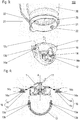
- a knife holder according to the present invention;
- Fig. 3:
- an exemplary embodiment of a jug combination according to the present invention;
- Fig. 4:
- construction details of an exemplary knife holder according to the present invention;
- Fig. 5a:
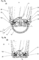
- a cross section of an exemplary jug combination when the jug is being connected to the knife holder while the barrier thereof obstructs the clutch;
- Fig. 5b:
- a cross section of the exemplary jug combination of
Figure 5a when the jug is fixed to the knife holder; and - Fig. 6:
- a base and a knife holder of a blender according to an exemplary embodiment of the present invention.
- In
Figure 1 , ablender 1000 according to an exemplary embodiment of the present invention is shown. Theblender 1000 comprises a base 30 with an electric motor included therein (not visible inFigure 1 ) and ajug combination 100 according to an exemplary embodiment of the present invention. Thejug combination 100 includes ajug 20 and aknife holder 10; for explanation purposes, theknife holder 10 is made visible inFigure 1 ; as is to be noted, however, thejug 20 does not have to be transparent. In the situation shown inFigure 1 , theknife holder 10 is coupled to an electric motor included in the base (and not visible inFigure 1 ). Thereby, rotatable knifes comprised by theknife holder 10 can be driven by means of the electric motor. - The coupling is realised by connection of a clutch element (not shown) of the base 30 with a clutch 12 comprised by the
knife holder 10, as visible inFigure 2 . - In said
Figure 2 , theknife holder 10 is shown in more detail and in another perspective than inFigure 1 . Although inFigure 2 a representation of the jug is omitted to provide a clear picture of theknife holder 10, the knife holder is depicted, inFigure 2 , still in a same condition as shown inFigure 1 , where the knife holder is mounted in the blender: In this state of the knife holder, thebarrier element 13 does not obstruct the clutch 12 (i.e., unblocks the clutch), whereby the clutch 12 is made accessible for the clutch element of the base and enabled to interact therewith. - To realise the deobstruction (i.e., the unblocking), the
barrier element 13, which is pivotable relative to the clutch 12, has been swivelled from a obstructing position (shown e.g. inFigure 3 ) into an unobstructing position. In this swivelling, pins 14a protruding through respective holes in the barrier element provide a respective axle for thebarrier element 13. In the present example, the axis of rotation formed thereby for the barrier element is orthogonal to a devised axis A of rotation of the clutch 12 (and the rotatable knifes 11). - The
pins 14a each are formed as respective protrusions of aslider 14. In the situation depicted inFigure 2 , thesliders 14 are pushed (by a jug not shown inFigure 2 ), against the elastic force of elastic elements (not visible inFigure 2 ), radially inwards with respect to the axis A. Only on that account,barrier element 13 could be swivelled into its unlocking position (in which it is shown inFigure 2 ), because a respective stopper surface of each of thesliders 14 otherwise abutting against a respective edge surface of thebarrier element 13 and, thereby, inhibiting rotation thereof, has been moved, by means of the pushing, away from thebarrier element 13. Thesliders 14 and the corresponding elastic elements thus form part of a snap mechanism which fixes, in an active state (namely, when the slider is not pushed radially inwards), thebarrier element 13 in its obstructing position, and which releases the barrier element in a deactivated state (namely, when the slider is pushed radially inwards), so as to adopt its unobstructing position. The functionality of the snap mechanism is further explained below with respect toFigures 4 ,5a and 5b . - In
Figure 3 , theknife holder 10 is shown prior to being connected to a jug 20 (which is partially shown only).Jug 20 andknife holder 10 together form ajug combination 100 according to an exemplary embodiment of the present invention. - In the situation shown in
Figure 3 , thebarrier element 13 is in its obstructing position, in which it obstructs the clutch 12, such that a connection thereof with a corresponding clutch element of a base is made impossible. In this state, thebarrier element 13 forms a handle, at which the knife holder may be easily and safely gripped and held by a user, such as when the user is cleaning the knife holder or when he is connecting it to the jug. - Moreover, in this state of the knife holder 10 (with the
barrier element 13 in its obstructing position), astopper surface 14b of theslider 14 abuts against anedge surface 13b of the barrier element and thus inhibits a rotation (i.e., a swivelling) of thebarrier element 13 around thepins 14a protruding throughholes 13a of the barrier element 13: This is seen fromFigure 4 showing an exploded view of theknife holder 10 in a cross section. In the present case, depending on a swivelling direction of thebarrier element 13, both opposite stopper surfaces 14b of theslider 14 may inhibit the swivelling of the barrier element. - When the
knife holder 10 and thejug 20 are being connected to each other as indicated inFigure 3 by slashed arrows, protrusions 22 (which in the depicted exemplary embodiment are wedge-shaped) at an inner surface of thejug 20 will push thepins 14a radially inwards (with respect to the devised axis A of rotation of the clutch 12, seeFigure 4 ) against the elastic force of elastic elements 15 (seeFigure 4 ). Thereby, thesliders 14 will be forced radially inwards, and said stopper surfaces 14b will be moved away from said edge surfaces 13b of thebarrier element 13, such that thebarrier element 13 is enabled to be swivelled into its unobstructing position (shown inFigure 2 ), thus making the clutch 12 accessible for a corresponding clutch element of a base of the blender. - Thus, the
sliders 14 and the corresponding elastic elements (which may be, in particular, springs) 15 together provide a respective snap mechanism 16 (seeFigure 4 ) which, in its active state as shown inFigure 3 , fixes thebarrier element 13 in its obstructing position, and which release the barrier element when they are deactivated by pushing therespective pins 14a radially inwards (with regard to the axis A). - As is further seen from
Figure 3 , thebarrier element 13 of theknife holder 10 exemplarily shown as an embodiment of the present invention further has anintake 13c for receiving, when the barrier element is in its obstructing position, afixation structure 21 of thejug 20. When thebarrier element 13 thereafter is swivelled, after being released by the deactivatedsnap mechanism 16, into its unobstructing position, aU-shaped frame 13d confining theintake 13c at least partially encompasses thefixation structure 21. Thereby, thejug 20 is safely and comfortably fixed to theknife holder 10. - The
knife holder 10 further comprises anose 17 configured to latch into a recess (not visible inFigur 3 ) of thebarrier element 13 when thebarrier element 13 is in its unobstructing position. Thereby, an unintended rotation of thebarrier element 13 and therewith, a loosening of theknife holder 10 from thejug 20 is inhibited even when the jug combination is lifted from a respective base. Preferably, the nose is configured to produce a sound, in particular a click, when it is latching into said recess of thebarrier element 13. - In the exemplary embodiment depicted in
Figure 3 , thejug 20 comprises acylindrical portion 25 configured to at least partially encompass theknife holder 10 with thebarrier element 13 swivelled into its unobstructing position. Thecylindrical portion 25 thus further protects the connection of theknife holder 10 with thejug 20. - In
Figures 5a and 5b , aninventive jug combination 100 is (partly, i.e. with thejug 20 truncated) shown in respective cross sections. As can be seen in these drawings, thejug 20 comprises ajug wall portion 23 and a holdingportion 24 which are (preferably detachably) connected to each other. Thejug wall portion 23 and the holdingportion 24 may be made a same or of different materials. In particular, the jug wall portion may at least partially be made of glass, and or the holdingportion 24 may be at least partially be made of metal, for example. -
Figure 5a depicts a situation in which the knife holder is being connected to thejug 20, but still not fully combined therewith. Thebarrier element 13 is in its obstructing position as described above and may serve as a handle for a user while he is performing the connection. - When the
knife holder 10 will be further moved towards thejug 20, as indicated by the arrow, thepins 14a will be pushed, by theprotrusions 22 of thejug 20, radially inwards (with regard to the devised axis A of rotation of the knifes 11). Thereby, thesliders 14 havingrespective stopper surfaces 14b (seeFigure 3 ) will be forced against theelastic elements 15, thus giving way for arespective edge surface 13b of thebarrier element 13 when this is swivelled, around thepins 14a, into its unobstructing position. - In
Figure 5b , thejug combination 100 is shown after such swivelling. Thebarrier element 13 thus is in its unobstructing position, such that the clutch 12 can be connected to a respective clutch element of a base. In this position,fixation structures 21 of thejug 20 each are encompassed by arespective frame 13d formed by the barrier element 13 (seeFigure 3 ), thus fixing theknife holder 10 and thejug 20 together. Thecylindrical portion 25 of thejug 20 at least partially encompasses the knife holder with itsbarrier element 13. -
Figure 6 shows theknife holder 10 separated from the base 30 (and the jug) of the blender depicted inFigure 1 . In the situation shown inFigure 6 , thebarrier element 13 is in its obstructing position, in which it inhibits a coupling of the knife holder's clutch (not visible inFigure 6 ) and the correspondingclutch element 31 of the base, by extending to an access area of the clutch. - Disclosed is a
knife holder 10 to be connected to ajug 20 for ablender 1000. Theknife holder 10 comprises a clutch 12, abarrier element 13 and asnap mechanism 16. The clutch 12 serves for coupling at least onerotatable knife 11 with abase 30 of the blender. Thebarrier element 13 is configured to obstruct the clutch 12 when the barrier element is in an obstructing position. Thesnap mechanism 16 is configured to fix, in an active state, thebarrier element 13 the obstructing position thereof, and to release thebarrier element 13 in a deactivated state. Thesnap mechanism 16 is configured to be operated, for transitioning from its active state into its deactivated state, by contact with thejug 20 when being connected therewith. - Further disclosed are a
jug combination 100 comprising aknife holder 10 and ajug 20, and ablender 1000 with a with ajug combination 100 and abase 30. -
- 10
- knife holder
- 11
- rotatable knife
- 12
- clutch
- 13
- barrier element
- 13a
- through hole
- 13b
- edge surface
- 13c
- intake
- 13d
- frame
- 14
- slider
- 14a
- pin of slider
- 14b
- stopper surface
- 15
- elastic element
- 16
- snap mechanism
- 20
- jug
- 21
- fixation structure
- 22
- protrusion
- 23
- jug wall portion
- 24
- holding portion
- 25
- cylindrical portion
- 30
- base
- 31
- clutch element
- 100
- jug combination
- 1000
- blender
- A
- devised axis of rotation of rotatable knife 1
Claims (10)
- Knife holder (10) for a blender (1000), the knife holder being configured to be connected to a jug (20) and to hold at least one rotatable knife (11), and comprising- a clutch (12) for coupling the at least one rotatable knife (11) with a base (30) of the blender;- a barrier element (13) for obstructing, in a obstructing position, the clutch (12) and- a snap mechanism (16) configured to fix, in an active state, the barrier element (13) in the obstructing position thereof, and to release the barrier element (13) when deactivated,
wherein the snap mechanism (16) is configured to be deactivated by contact with the jug (20) when being connected therewith. - Knife holder according to claim 1, wherein the barrier element (13) is pivotable relative to the clutch (12).
- Knife holder according to claim 1 or 2, wherein the barrier element (13) has an intake (13c) for receiving, in the obstructing position, a fixation structure (21) of the jug (20), and for at least partially encompassing the fixation structure (21) when removed from the obstructing position.
- Knife holder according to one of the preceding claims, wherein the snap mechanism (16) comprises at least one slider element (14) configured to be pushed radially inwards for deactivating the snap mechanism (16).
- Knife holder according to claim 4, wherein the at least one slider element (14) comprises a pin (14a) forming an axle for the barrier element (13).
- Jug combination (100) for a blender (1000), the jug combination comprising a knife holder (10) according to one of the preceding claims and a jug (20) detachably connectable to the knife holder.
- Jug combination according to claim 6, wherein the jug (20) has a protrusion (22) configured to contact the snap mechanism (16) of the knife holder when the jug is combined with the knife holder, so as to deactivate the snap mechanism (16).
- Jug combination according to one of claims 6 or 7, wherein the jug comprises a cylindrical portion (25) configured to at least partially surround the knife holder (10), when connected thereto, with the barrier element (13) in its unobstructing position.
- Jug combination according to one of claims 6 to 8, wherein the knife holder (10) is in accordance with claim 3 and wherein the jug comprises a fixation structure (21) corresponding to the intake (13c) of the barrier element (13).
- Blender (1000) comprising a jug combination (100) according to one of claims 6 to 8 and a base (30) with an electric motor to be coupled with the at least one knife of the knife holder.
Priority Applications (5)
| Application Number | Priority Date | Filing Date | Title |
|---|---|---|---|
| PL20163011.8T PL3878329T3 (en) | 2020-03-13 | 2020-03-13 | Knife holder, jug combination and blender |
| ES20163011T ES2927398T3 (en) | 2020-03-13 | 2020-03-13 | Knife holder, blender jug combination |
| EP20163011.8A EP3878329B1 (en) | 2020-03-13 | 2020-03-13 | Knife holder, jug combination and blender |
| CN202180020210.5A CN115209772B (en) | 2020-03-13 | 2021-02-25 | Knife holder, jug combination and blender |
| PCT/EP2021/054669 WO2021180479A1 (en) | 2020-03-13 | 2021-02-25 | Knife holder, jug combination and blender |
Applications Claiming Priority (1)
| Application Number | Priority Date | Filing Date | Title |
|---|---|---|---|
| EP20163011.8A EP3878329B1 (en) | 2020-03-13 | 2020-03-13 | Knife holder, jug combination and blender |
Publications (2)
| Publication Number | Publication Date |
|---|---|
| EP3878329A1 true EP3878329A1 (en) | 2021-09-15 |
| EP3878329B1 EP3878329B1 (en) | 2022-08-24 |
Family
ID=69844494
Family Applications (1)
| Application Number | Title | Priority Date | Filing Date |
|---|---|---|---|
| EP20163011.8A Active EP3878329B1 (en) | 2020-03-13 | 2020-03-13 | Knife holder, jug combination and blender |
Country Status (5)
| Country | Link |
|---|---|
| EP (1) | EP3878329B1 (en) |
| CN (1) | CN115209772B (en) |
| ES (1) | ES2927398T3 (en) |
| PL (1) | PL3878329T3 (en) |
| WO (1) | WO2021180479A1 (en) |
Cited By (1)
| Publication number | Priority date | Publication date | Assignee | Title |
|---|---|---|---|---|
| EP4169421A1 (en) * | 2021-10-25 | 2023-04-26 | Bodyshake GmbH | Device for preparing a mixed beverage and method for assembling and manufacturing the device |
Citations (2)
| Publication number | Priority date | Publication date | Assignee | Title |
|---|---|---|---|---|
| WO2000024302A1 (en) * | 1998-10-23 | 2000-05-04 | Koninklijke Philips Electronics N.V. | Food-processor accessory having a safety member |
| WO2016120021A1 (en) * | 2015-01-30 | 2016-08-04 | BSH Hausgeräte GmbH | Mixing tool lock for a kitchen appliance |
Family Cites Families (10)
| Publication number | Priority date | Publication date | Assignee | Title |
|---|---|---|---|---|
| DE19912750A1 (en) * | 1999-03-22 | 2000-09-28 | Braun Gmbh | Safety device for a cup mixer |
| DE102006030222B4 (en) * | 2006-06-30 | 2011-04-07 | BSH Bosch und Siemens Hausgeräte GmbH | Hand stirrer with safety lock |
| AU2011340785B2 (en) * | 2010-12-07 | 2017-03-02 | Breville Pty Limited | Blender jug and coupling |
| WO2013020571A1 (en) * | 2011-08-05 | 2013-02-14 | Dkb Household Switzerland Ag | Hand-held blender |
| US20130188443A1 (en) * | 2012-01-19 | 2013-07-25 | Christina Ruth Alvarez | Reversible Blender Jug |
| JP5857166B2 (en) * | 2012-10-05 | 2016-02-10 | コーニンクレッカ フィリップス エヌ ヴェKoninklijke Philips N.V. | Multi-function jug and beverage making machine using multi-function jug |
| DE102013205545A1 (en) * | 2013-03-28 | 2014-10-02 | BSH Bosch und Siemens Hausgeräte GmbH | Processing attachment with intervention protection |
| MX2019006323A (en) * | 2016-11-30 | 2021-08-19 | Enegi Brands Inc | Portable blender set. |
| US10898028B2 (en) * | 2017-06-30 | 2021-01-26 | Capbran Holdings, Llc | Mixer with safety mechanisms |
| EP3517002B1 (en) * | 2018-01-26 | 2022-09-28 | BSH Hausgeräte GmbH | Electric blender |
-
2020
- 2020-03-13 ES ES20163011T patent/ES2927398T3/en active Active
- 2020-03-13 PL PL20163011.8T patent/PL3878329T3/en unknown
- 2020-03-13 EP EP20163011.8A patent/EP3878329B1/en active Active
-
2021
- 2021-02-25 WO PCT/EP2021/054669 patent/WO2021180479A1/en not_active Ceased
- 2021-02-25 CN CN202180020210.5A patent/CN115209772B/en active Active
Patent Citations (2)
| Publication number | Priority date | Publication date | Assignee | Title |
|---|---|---|---|---|
| WO2000024302A1 (en) * | 1998-10-23 | 2000-05-04 | Koninklijke Philips Electronics N.V. | Food-processor accessory having a safety member |
| WO2016120021A1 (en) * | 2015-01-30 | 2016-08-04 | BSH Hausgeräte GmbH | Mixing tool lock for a kitchen appliance |
Cited By (2)
| Publication number | Priority date | Publication date | Assignee | Title |
|---|---|---|---|---|
| EP4169421A1 (en) * | 2021-10-25 | 2023-04-26 | Bodyshake GmbH | Device for preparing a mixed beverage and method for assembling and manufacturing the device |
| WO2023072939A1 (en) | 2021-10-25 | 2023-05-04 | Bodyshake Gmbh | Apparatus for preparing a mixed drink, and method for assembling and producing the apparatus |
Also Published As
| Publication number | Publication date |
|---|---|
| CN115209772B (en) | 2025-09-05 |
| PL3878329T3 (en) | 2022-12-27 |
| WO2021180479A1 (en) | 2021-09-16 |
| ES2927398T3 (en) | 2022-11-04 |
| EP3878329B1 (en) | 2022-08-24 |
| CN115209772A (en) | 2022-10-18 |
Similar Documents
| Publication | Publication Date | Title |
|---|---|---|
| EP2572221B1 (en) | Locking optical and/or electrical connectors and cable assemblies | |
| EP0692899B1 (en) | Foldable portable wireless telephone apparatus | |
| US7501198B2 (en) | Sterile transfer battery container | |
| KR100428794B1 (en) | Docking mechanism used for assembling/disassembling peripheral device of computer | |
| US20110194828A1 (en) | Block-Out Device for Fiber Optic Adapter | |
| EP3878329B1 (en) | Knife holder, jug combination and blender | |
| CN110230429B (en) | Handle device with internal lock | |
| CN118215420A (en) | Coupling and uncoupling of main housing and functional accessories of handheld personal care device | |
| KR200443388Y1 (en) | Battery handle | |
| CN100433469C (en) | Protective cover and removal tool | |
| WO2000008714A2 (en) | Safety plug socket | |
| JPH119549A (en) | Camera connector with endoscope | |
| JP2022530700A (en) | Coupling assembly used in personal care equipment | |
| JP2001046131A (en) | Bottom runner of umbrella | |
| JPH0678434A (en) | Floor wiring device | |
| JP2818488B2 (en) | Cooking utensil with annular handle | |
| KR20170135704A (en) | Removable gripping device for ear-shaped holding member of a kitchen utensil | |
| US7357581B2 (en) | Fibre optic transceiver | |
| US20080158696A1 (en) | Handheld magnifier with releasable magnifying lens | |
| EP2713630A1 (en) | Hearing aid device with a lockable battery compartment and method for manufacturing such a hearing aid device | |
| EP1202395B1 (en) | Security seal | |
| US20250043553A1 (en) | Magnetic shower head | |
| CN2390531Y (en) | Safety protection device for electric fryer | |
| KR102567718B1 (en) | Door lock apparatus without handling for rotation of door knob | |
| CN213882816U (en) | Pot body subassembly and have its cooking utensil |
Legal Events
| Date | Code | Title | Description |
|---|---|---|---|
| PUAI | Public reference made under article 153(3) epc to a published international application that has entered the european phase |
Free format text: ORIGINAL CODE: 0009012 |
|
| STAA | Information on the status of an ep patent application or granted ep patent |
Free format text: STATUS: THE APPLICATION HAS BEEN PUBLISHED |
|
| AK | Designated contracting states |
Kind code of ref document: A1 Designated state(s): AL AT BE BG CH CY CZ DE DK EE ES FI FR GB GR HR HU IE IS IT LI LT LU LV MC MK MT NL NO PL PT RO RS SE SI SK SM TR |
|
| STAA | Information on the status of an ep patent application or granted ep patent |
Free format text: STATUS: REQUEST FOR EXAMINATION WAS MADE |
|
| GRAP | Despatch of communication of intention to grant a patent |
Free format text: ORIGINAL CODE: EPIDOSNIGR1 |
|
| STAA | Information on the status of an ep patent application or granted ep patent |
Free format text: STATUS: GRANT OF PATENT IS INTENDED |
|
| 17P | Request for examination filed |
Effective date: 20220315 |
|
| RBV | Designated contracting states (corrected) |
Designated state(s): AL AT BE BG CH CY CZ DE DK EE ES FI FR GB GR HR HU IE IS IT LI LT LU LV MC MK MT NL NO PL PT RO RS SE SI SK SM TR |
|
| INTG | Intention to grant announced |
Effective date: 20220419 |
|
| GRAS | Grant fee paid |
Free format text: ORIGINAL CODE: EPIDOSNIGR3 |
|
| GRAA | (expected) grant |
Free format text: ORIGINAL CODE: 0009210 |
|
| STAA | Information on the status of an ep patent application or granted ep patent |
Free format text: STATUS: THE PATENT HAS BEEN GRANTED |
|
| AK | Designated contracting states |
Kind code of ref document: B1 Designated state(s): AL AT BE BG CH CY CZ DE DK EE ES FI FR GB GR HR HU IE IS IT LI LT LU LV MC MK MT NL NO PL PT RO RS SE SI SK SM TR |
|
| REG | Reference to a national code |
Ref country code: CH Ref legal event code: EP |
|
| REG | Reference to a national code |
Ref country code: DE Ref legal event code: R096 Ref document number: 602020004631 Country of ref document: DE |
|
| REG | Reference to a national code |
Ref country code: IE Ref legal event code: FG4D |
|
| REG | Reference to a national code |
Ref country code: AT Ref legal event code: REF Ref document number: 1513086 Country of ref document: AT Kind code of ref document: T Effective date: 20220915 |
|
| REG | Reference to a national code |
Ref country code: SE Ref legal event code: TRGR |
|
| REG | Reference to a national code |
Ref country code: ES Ref legal event code: FG2A Ref document number: 2927398 Country of ref document: ES Kind code of ref document: T3 Effective date: 20221104 |
|
| REG | Reference to a national code |
Ref country code: LT Ref legal event code: MG9D |
|
| REG | Reference to a national code |
Ref country code: NL Ref legal event code: MP Effective date: 20220824 |
|
| PG25 | Lapsed in a contracting state [announced via postgrant information from national office to epo] |
Ref country code: RS Free format text: LAPSE BECAUSE OF FAILURE TO SUBMIT A TRANSLATION OF THE DESCRIPTION OR TO PAY THE FEE WITHIN THE PRESCRIBED TIME-LIMIT Effective date: 20220824 Ref country code: PT Free format text: LAPSE BECAUSE OF FAILURE TO SUBMIT A TRANSLATION OF THE DESCRIPTION OR TO PAY THE FEE WITHIN THE PRESCRIBED TIME-LIMIT Effective date: 20221226 Ref country code: NO Free format text: LAPSE BECAUSE OF FAILURE TO SUBMIT A TRANSLATION OF THE DESCRIPTION OR TO PAY THE FEE WITHIN THE PRESCRIBED TIME-LIMIT Effective date: 20221124 Ref country code: NL Free format text: LAPSE BECAUSE OF FAILURE TO SUBMIT A TRANSLATION OF THE DESCRIPTION OR TO PAY THE FEE WITHIN THE PRESCRIBED TIME-LIMIT Effective date: 20220824 Ref country code: LV Free format text: LAPSE BECAUSE OF FAILURE TO SUBMIT A TRANSLATION OF THE DESCRIPTION OR TO PAY THE FEE WITHIN THE PRESCRIBED TIME-LIMIT Effective date: 20220824 Ref country code: LT Free format text: LAPSE BECAUSE OF FAILURE TO SUBMIT A TRANSLATION OF THE DESCRIPTION OR TO PAY THE FEE WITHIN THE PRESCRIBED TIME-LIMIT Effective date: 20220824 Ref country code: FI Free format text: LAPSE BECAUSE OF FAILURE TO SUBMIT A TRANSLATION OF THE DESCRIPTION OR TO PAY THE FEE WITHIN THE PRESCRIBED TIME-LIMIT Effective date: 20220824 |
|
| REG | Reference to a national code |
Ref country code: AT Ref legal event code: MK05 Ref document number: 1513086 Country of ref document: AT Kind code of ref document: T Effective date: 20220824 |
|
| PG25 | Lapsed in a contracting state [announced via postgrant information from national office to epo] |
Ref country code: IS Free format text: LAPSE BECAUSE OF FAILURE TO SUBMIT A TRANSLATION OF THE DESCRIPTION OR TO PAY THE FEE WITHIN THE PRESCRIBED TIME-LIMIT Effective date: 20221224 Ref country code: HR Free format text: LAPSE BECAUSE OF FAILURE TO SUBMIT A TRANSLATION OF THE DESCRIPTION OR TO PAY THE FEE WITHIN THE PRESCRIBED TIME-LIMIT Effective date: 20220824 Ref country code: GR Free format text: LAPSE BECAUSE OF FAILURE TO SUBMIT A TRANSLATION OF THE DESCRIPTION OR TO PAY THE FEE WITHIN THE PRESCRIBED TIME-LIMIT Effective date: 20221125 |
|
| PG25 | Lapsed in a contracting state [announced via postgrant information from national office to epo] |
Ref country code: SM Free format text: LAPSE BECAUSE OF FAILURE TO SUBMIT A TRANSLATION OF THE DESCRIPTION OR TO PAY THE FEE WITHIN THE PRESCRIBED TIME-LIMIT Effective date: 20220824 Ref country code: RO Free format text: LAPSE BECAUSE OF FAILURE TO SUBMIT A TRANSLATION OF THE DESCRIPTION OR TO PAY THE FEE WITHIN THE PRESCRIBED TIME-LIMIT Effective date: 20220824 Ref country code: DK Free format text: LAPSE BECAUSE OF FAILURE TO SUBMIT A TRANSLATION OF THE DESCRIPTION OR TO PAY THE FEE WITHIN THE PRESCRIBED TIME-LIMIT Effective date: 20220824 Ref country code: CZ Free format text: LAPSE BECAUSE OF FAILURE TO SUBMIT A TRANSLATION OF THE DESCRIPTION OR TO PAY THE FEE WITHIN THE PRESCRIBED TIME-LIMIT Effective date: 20220824 Ref country code: AT Free format text: LAPSE BECAUSE OF FAILURE TO SUBMIT A TRANSLATION OF THE DESCRIPTION OR TO PAY THE FEE WITHIN THE PRESCRIBED TIME-LIMIT Effective date: 20220824 |
|
| REG | Reference to a national code |
Ref country code: DE Ref legal event code: R097 Ref document number: 602020004631 Country of ref document: DE |
|
| PG25 | Lapsed in a contracting state [announced via postgrant information from national office to epo] |
Ref country code: SK Free format text: LAPSE BECAUSE OF FAILURE TO SUBMIT A TRANSLATION OF THE DESCRIPTION OR TO PAY THE FEE WITHIN THE PRESCRIBED TIME-LIMIT Effective date: 20220824 Ref country code: EE Free format text: LAPSE BECAUSE OF FAILURE TO SUBMIT A TRANSLATION OF THE DESCRIPTION OR TO PAY THE FEE WITHIN THE PRESCRIBED TIME-LIMIT Effective date: 20220824 |
|
| P01 | Opt-out of the competence of the unified patent court (upc) registered |
Effective date: 20230510 |
|
| PG25 | Lapsed in a contracting state [announced via postgrant information from national office to epo] |
Ref country code: AL Free format text: LAPSE BECAUSE OF FAILURE TO SUBMIT A TRANSLATION OF THE DESCRIPTION OR TO PAY THE FEE WITHIN THE PRESCRIBED TIME-LIMIT Effective date: 20220824 |
|
| PLBE | No opposition filed within time limit |
Free format text: ORIGINAL CODE: 0009261 |
|
| STAA | Information on the status of an ep patent application or granted ep patent |
Free format text: STATUS: NO OPPOSITION FILED WITHIN TIME LIMIT |
|
| 26N | No opposition filed |
Effective date: 20230525 |
|
| PG25 | Lapsed in a contracting state [announced via postgrant information from national office to epo] |
Ref country code: SI Free format text: LAPSE BECAUSE OF FAILURE TO SUBMIT A TRANSLATION OF THE DESCRIPTION OR TO PAY THE FEE WITHIN THE PRESCRIBED TIME-LIMIT Effective date: 20220824 |
|
| PG25 | Lapsed in a contracting state [announced via postgrant information from national office to epo] |
Ref country code: MC Free format text: LAPSE BECAUSE OF FAILURE TO SUBMIT A TRANSLATION OF THE DESCRIPTION OR TO PAY THE FEE WITHIN THE PRESCRIBED TIME-LIMIT Effective date: 20220824 |
|
| REG | Reference to a national code |
Ref country code: CH Ref legal event code: PL |
|
| REG | Reference to a national code |
Ref country code: BE Ref legal event code: MM Effective date: 20230331 |
|
| PG25 | Lapsed in a contracting state [announced via postgrant information from national office to epo] |
Ref country code: LU Free format text: LAPSE BECAUSE OF NON-PAYMENT OF DUE FEES Effective date: 20230313 |
|
| REG | Reference to a national code |
Ref country code: IE Ref legal event code: MM4A |
|
| PG25 | Lapsed in a contracting state [announced via postgrant information from national office to epo] |
Ref country code: LI Free format text: LAPSE BECAUSE OF NON-PAYMENT OF DUE FEES Effective date: 20230331 Ref country code: IE Free format text: LAPSE BECAUSE OF NON-PAYMENT OF DUE FEES Effective date: 20230313 Ref country code: CH Free format text: LAPSE BECAUSE OF NON-PAYMENT OF DUE FEES Effective date: 20230331 |
|
| PG25 | Lapsed in a contracting state [announced via postgrant information from national office to epo] |
Ref country code: BE Free format text: LAPSE BECAUSE OF NON-PAYMENT OF DUE FEES Effective date: 20230331 |
|
| PG25 | Lapsed in a contracting state [announced via postgrant information from national office to epo] |
Ref country code: IT Free format text: LAPSE BECAUSE OF FAILURE TO SUBMIT A TRANSLATION OF THE DESCRIPTION OR TO PAY THE FEE WITHIN THE PRESCRIBED TIME-LIMIT Effective date: 20220824 |
|
| PG25 | Lapsed in a contracting state [announced via postgrant information from national office to epo] |
Ref country code: BG Free format text: LAPSE BECAUSE OF FAILURE TO SUBMIT A TRANSLATION OF THE DESCRIPTION OR TO PAY THE FEE WITHIN THE PRESCRIBED TIME-LIMIT Effective date: 20220824 |
|
| PG25 | Lapsed in a contracting state [announced via postgrant information from national office to epo] |
Ref country code: BG Free format text: LAPSE BECAUSE OF FAILURE TO SUBMIT A TRANSLATION OF THE DESCRIPTION OR TO PAY THE FEE WITHIN THE PRESCRIBED TIME-LIMIT Effective date: 20220824 |
|
| PGFP | Annual fee paid to national office [announced via postgrant information from national office to epo] |
Ref country code: ES Payment date: 20250416 Year of fee payment: 6 |
|
| PG25 | Lapsed in a contracting state [announced via postgrant information from national office to epo] |
Ref country code: CY Free format text: LAPSE BECAUSE OF FAILURE TO SUBMIT A TRANSLATION OF THE DESCRIPTION OR TO PAY THE FEE WITHIN THE PRESCRIBED TIME-LIMIT; INVALID AB INITIO Effective date: 20200313 |
|
| PG25 | Lapsed in a contracting state [announced via postgrant information from national office to epo] |
Ref country code: HU Free format text: LAPSE BECAUSE OF FAILURE TO SUBMIT A TRANSLATION OF THE DESCRIPTION OR TO PAY THE FEE WITHIN THE PRESCRIBED TIME-LIMIT; INVALID AB INITIO Effective date: 20200313 |
|
| PG25 | Lapsed in a contracting state [announced via postgrant information from national office to epo] |
Ref country code: TR Free format text: LAPSE BECAUSE OF FAILURE TO SUBMIT A TRANSLATION OF THE DESCRIPTION OR TO PAY THE FEE WITHIN THE PRESCRIBED TIME-LIMIT Effective date: 20220824 |
|
| PGFP | Annual fee paid to national office [announced via postgrant information from national office to epo] |
Ref country code: SE Payment date: 20260323 Year of fee payment: 7 |
|
| PGFP | Annual fee paid to national office [announced via postgrant information from national office to epo] |
Ref country code: GB Payment date: 20260324 Year of fee payment: 7 |
|
| PGFP | Annual fee paid to national office [announced via postgrant information from national office to epo] |
Ref country code: DE Payment date: 20260331 Year of fee payment: 7 |
|
| PGFP | Annual fee paid to national office [announced via postgrant information from national office to epo] |
Ref country code: FR Payment date: 20260324 Year of fee payment: 7 |
|
| PGFP | Annual fee paid to national office [announced via postgrant information from national office to epo] |
Ref country code: PL Payment date: 20260306 Year of fee payment: 7 |