EP3878200B1 - Adaptation de mesurage basée sur un renforcement de canal - Google Patents
Adaptation de mesurage basée sur un renforcement de canal Download PDFInfo
- Publication number
- EP3878200B1 EP3878200B1 EP19801292.4A EP19801292A EP3878200B1 EP 3878200 B1 EP3878200 B1 EP 3878200B1 EP 19801292 A EP19801292 A EP 19801292A EP 3878200 B1 EP3878200 B1 EP 3878200B1
- Authority
- EP
- European Patent Office
- Prior art keywords
- parameter
- measurement
- measurements
- channel
- changing
- Prior art date
- Legal status (The legal status is an assumption and is not a legal conclusion. Google has not performed a legal analysis and makes no representation as to the accuracy of the status listed.)
- Active
Links
- 238000005259 measurement Methods 0.000 title claims description 335
- 230000006978 adaptation Effects 0.000 title description 4
- 238000000034 method Methods 0.000 claims description 59
- 238000012935 Averaging Methods 0.000 claims description 36
- 230000001427 coherent effect Effects 0.000 claims description 31
- 230000005540 biological transmission Effects 0.000 claims description 19
- 238000005457 optimization Methods 0.000 claims description 18
- 230000011664 signaling Effects 0.000 claims description 16
- 230000003247 decreasing effect Effects 0.000 claims description 14
- 230000008859 change Effects 0.000 claims description 10
- 235000019527 sweetened beverage Nutrition 0.000 claims 1
- 238000001914 filtration Methods 0.000 description 44
- 239000000523 sample Substances 0.000 description 34
- 230000009471 action Effects 0.000 description 16
- 238000001514 detection method Methods 0.000 description 14
- 238000011156 evaluation Methods 0.000 description 13
- 235000019580 granularity Nutrition 0.000 description 13
- 230000000694 effects Effects 0.000 description 10
- 230000006870 function Effects 0.000 description 10
- 230000008901 benefit Effects 0.000 description 8
- 238000005562 fading Methods 0.000 description 7
- 238000010586 diagram Methods 0.000 description 6
- 238000005070 sampling Methods 0.000 description 6
- 238000007596 consolidation process Methods 0.000 description 5
- 230000000875 corresponding effect Effects 0.000 description 5
- 238000007726 management method Methods 0.000 description 5
- 230000008569 process Effects 0.000 description 5
- 239000000969 carrier Substances 0.000 description 4
- 238000004590 computer program Methods 0.000 description 4
- 238000012545 processing Methods 0.000 description 4
- 230000004044 response Effects 0.000 description 4
- 238000013461 design Methods 0.000 description 3
- 230000007774 longterm Effects 0.000 description 3
- 238000013468 resource allocation Methods 0.000 description 3
- 238000012360 testing method Methods 0.000 description 3
- 238000003491 array Methods 0.000 description 2
- 238000004891 communication Methods 0.000 description 2
- 239000002131 composite material Substances 0.000 description 2
- 230000001934 delay Effects 0.000 description 2
- 230000001419 dependent effect Effects 0.000 description 2
- 239000006185 dispersion Substances 0.000 description 2
- 230000000737 periodic effect Effects 0.000 description 2
- 230000009467 reduction Effects 0.000 description 2
- 240000006829 Ficus sundaica Species 0.000 description 1
- 230000002776 aggregation Effects 0.000 description 1
- 238000004220 aggregation Methods 0.000 description 1
- 238000004458 analytical method Methods 0.000 description 1
- 238000013459 approach Methods 0.000 description 1
- 230000009286 beneficial effect Effects 0.000 description 1
- 230000000903 blocking effect Effects 0.000 description 1
- 238000012512 characterization method Methods 0.000 description 1
- 230000002596 correlated effect Effects 0.000 description 1
- 238000013500 data storage Methods 0.000 description 1
- 238000009795 derivation Methods 0.000 description 1
- 230000003292 diminished effect Effects 0.000 description 1
- 230000009977 dual effect Effects 0.000 description 1
- 238000009499 grossing Methods 0.000 description 1
- 230000000116 mitigating effect Effects 0.000 description 1
- 230000003287 optical effect Effects 0.000 description 1
- 230000035515 penetration Effects 0.000 description 1
- 230000000704 physical effect Effects 0.000 description 1
- 238000013442 quality metrics Methods 0.000 description 1
- 230000002040 relaxant effect Effects 0.000 description 1
- 230000003595 spectral effect Effects 0.000 description 1
- 238000001228 spectrum Methods 0.000 description 1
- 238000007619 statistical method Methods 0.000 description 1
- 230000001960 triggered effect Effects 0.000 description 1
Images


Classifications
-
- H—ELECTRICITY
- H04—ELECTRIC COMMUNICATION TECHNIQUE
- H04W—WIRELESS COMMUNICATION NETWORKS
- H04W24/00—Supervisory, monitoring or testing arrangements
- H04W24/08—Testing, supervising or monitoring using real traffic
-
- H—ELECTRICITY
- H04—ELECTRIC COMMUNICATION TECHNIQUE
- H04W—WIRELESS COMMUNICATION NETWORKS
- H04W24/00—Supervisory, monitoring or testing arrangements
- H04W24/02—Arrangements for optimising operational condition
-
- H—ELECTRICITY
- H04—ELECTRIC COMMUNICATION TECHNIQUE
- H04W—WIRELESS COMMUNICATION NETWORKS
- H04W16/00—Network planning, e.g. coverage or traffic planning tools; Network deployment, e.g. resource partitioning or cells structures
- H04W16/24—Cell structures
- H04W16/28—Cell structures using beam steering
-
- H—ELECTRICITY
- H04—ELECTRIC COMMUNICATION TECHNIQUE
- H04W—WIRELESS COMMUNICATION NETWORKS
- H04W28/00—Network traffic management; Network resource management
- H04W28/16—Central resource management; Negotiation of resources or communication parameters, e.g. negotiating bandwidth or QoS [Quality of Service]
Definitions
- Procedures such as initial access, handover, and radio resource allocation each rely on accurate channel quality estimation.
- a base station (BS) e.g., gNB, eNB
- UE user equipment
- LTE and NR measurement models are different, since NR is being standardized by 3GPP to rely heavily on beamforming, especially in the higher frequencies to overcome the propagation challenges in this part of the spectrum.
- NR is expected to have more synchronization and reference signals to be monitored than in LTE.
- RRM radio resource management
- FIG. 1 includes "Layer 1 filtering”, “Layer 3 filtering”, and “Evaluation of reporting criteria.” These modules, and their inputs and outputs, are described below.
- Layer 1 filtering will introduce a certain level of measurement averaging. How and when the UE exactly performs the required measurements will be implementation specific to the point that the output at B fulfils the performance requirements specified. Layer 3 filtering and parameters used are also specified and do not introduce any delay in the sample availability between B and C. Measurement at point C, C' is the input used in the event evaluation.
- Layer 3 (L3) filtering is further detailed in TS 36.331 at 5.5.3.2.
- the standard indicates that the UE shall: 1> for each measurement quantity that the UE performs measurements according to 5.5.3.1: NOTE 1: This does not include quantities configured solely for UE Rx-Tx time difference, SSTD measurements and RSSI, channel occupancy measurements, WLAN measurements of Band, Carrier Info, Available Admission Capacity, Backhaul Bandwidth, Channel Utilization, and Station Count, CBR measurement, sensing measurement and UL PDCP Packet Delay per QCI measurement i.e. for those types of measurements the UE ignores the triggerQuantity and reportQuantity.
- DRX is configured by the network so the UE does not have to monitor control channels during pre-defined periods but use these for actions, such as perform measurements.
- Identification of a cell shall include detection of the cell and additionally performing a single measurement with measurement period of T Measurement_Period Intra . If higher layer filtering is used (i.e. L3 filtering), an additional cell identification delay can be expected. That suggests that the usage of higher layer filtering implies longer delays in performing measurements.
- higher layer filtering i.e. L3 filtering
- the UE When no measurement gaps are activated, the UE shall be capable of performing RSRP, RSRQ, and RS-SINR measurements for 8 identified-intra-frequency cells, and the UE physical layer shall be capable of reporting measurements to higher layers with the measurement period of 200 ms.
- the measurement period for intra frequency measurements is 200 ms. That means that the neighbour cell measurements are averaged over a long time period, in the order of 200 ms or even longer, to filter out the effect of small scale fading.
- Cell measurements in LTE and NR have the following measurement quantities associated: RSRP, RSRQ and SINR.
- the L1 is required to provide a sample to the RRC layer. However, it is not directly specified how these samples are computed in terms of averaging in the time domain which may occur within these 200 ms.
- the overall neighbour cell measurement quantity results comprise non-coherent averaging of 2 or more basic non-coherent averaged samples.
- An example of RSRP measurement averaging in E-UTRAN is shown in FIG. 2 .
- FIG. 2 illustrates that the UE obtains the overall measurement quantity result by collecting four non-coherent averaged samples or snapshots, each of 3 ms length in this example, during the physical layer measurement period, e.g. 200 ms. Every coherent averaged sample is 1 ms long. In this example, a 3 ms non-coherent sample comprises 3 consecutive coherent samples.
- the measurement accuracy of the neighbour cell measurement quantity e.g. RSRP or RSRQ
- the sampling rate is UE implementation specific. Therefore, in another implementation a UE may use only 3 snapshots over a 200 ms interval or measurement period. Regardless of the sampling rate, it is important that the measured quantity fulfils the performance requirements in terms of the specified measurement accuracy.
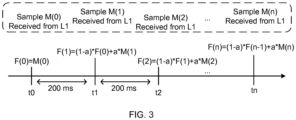
- L3 filtering is configured by the network, to mitigate the effects of fading and possibly avoid ping-pong handovers based on a decision of a temporary sample that is too good, the L3 performs a filtering procedure that considers a previously filtered value (from the sample received in the past 200 ms) and the new sample.
- FIG. 3 illustrates the L3 filtering that is performed.
- the goal of the neighbour cell quality measurement is to estimate and predict the long term downlink quality that can be experienced by the UE in a particular cell or beam, in the case of NR. It should indeed indicate the signal quality or throughput that the UE will achieve in a cell. This prediction enables the UE and the network to choose the most appropriate cell when performing cell reselection and handovers, respectively.
- any set of resource blocks i.e. part of the cell bandwidth
- the quality measurement should capture the overall long-term average quality over the entire bandwidth or at least over the largest possible portion of the bandwidth. This is in contrast with E-UTRAN Cell of Interest (COI) measurement, which typically depicts short term quality of possibly a subset of the resource blocks from the serving cell.
- COI E-UTRAN Cell of Interest
- Beamforming where multiple antenna elements are used to form narrow beams, is an efficient tool for improving both data rates and capacity. Its extensive use, in particular at the network side, is an essential part of high-frequency wireless access in order to overcome the propagation challenges highlighted earlier. The operation in higher frequencies is one of the drivers for beamforming based solutions since high frequencies makes it possible to use smaller antenna elements enabling deployments of larger antenna arrays.
- the 5G radio interface currently being standardized in 3GPP has been designed considering that physical channels (e.g., PDCCH, PDSCH, PUCCH, etc.) and reference signals for control plane procedures (such as measurements for mobility, link adaptation, channel status reporting, etc.) will rely heavily on beamforming.
- physical channels e.g., PDCCH, PDSCH, PUCCH, etc.
- reference signals for control plane procedures such as measurements for mobility, link adaptation, channel status reporting, etc.
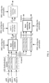
- FIG. 4 includes modules for "Layer 1 filtering” (for each respective gNB beam), “Layer 3 filtering” and “Evaluation of reporting criteria”. Additionally, FIG. 4 also includes "Beam consolidation/selection” and “Beam selection for reporting” modules, as well as individual Layer 3 filtering for each gNB beam. These modules, and their inputs and outputs, are described below.
- K beams correspond to the measurements on NR Synchronization Signal (SS) block or channel state information reference signal (CSI-RS) resources configured for L3 mobility by gNB and detected by UE at L1.
- SS Synchronization Signal
- CSI-RS channel state information reference signal
- A measurements (beam specific samples) internal to the physical layer.
- Layer 1 filtering internal layer 1 filtering of the inputs measured at point A. Exact filtering is implementation dependent. How the measurements are actually executed in the physical layer by an implementation (inputs A and Layer 1 filtering) in not constrained by the standard.
- A1 measurements (i.e. beam specific measurements) reported by layer 1 to layer 3 after layer 1 filtering.
- Beam Consolidation/Selection beam specific measurements are consolidated to derive cell quality.
- the behaviour of the Beam consolidation/selection is standardised and the configuration of this module is provided by RRC signalling.
- Reporting period at B equals one measurement period at A1.
- B a measurement (i.e. cell quality) derived from beam-specific measurements reported to layer 3 after beam consolidation/selection.
- Layer 3 filtering for cell quality filtering performed on the measurements provided at point B.
- the behaviour of the Layer 3 filters is standardised and the configuration of the layer 3 filters is provided by RRC signalling. Filtering reporting period at C equals one measurement period at B.
- reporting rate is identical to the reporting rate at point B. This measurement is used as input for one or more evaluation of reporting criteria.
- Evaluation of reporting criteria checks whether actual measurement reporting is necessary at point D.
- the evaluation can be based on more than one flow of measurements at reference point C e.g. to compare between different measurements. This is illustrated by input C and C1.
- the UE shall evaluate the reporting criteria at least every time a new measurement result is reported at point C, C1.
- the reporting criteria are standardised and the configuration is provided by RRC signalling (UE measurements).
- L3 Beam filtering filtering performed on the measurements (i.e. beam specific measurements) provided at point A1.
- the behaviour of the beam filters is standardised and the configuration of the beam filters is provided by RRC signalling.
- Filtering reporting period at E equals one measurement period at A1.
- E a measurement (i.e. beam-specific measurement) after processing in the beam filter.
- the reporting rate is identical to the reporting rate at point A1. This measurement is used as input for selecting the X measurements to be reported.
- Beam Selection for beam reporting selects the X measurements from the measurements provided at point E.
- the behaviour of the beam selection is standardised and the configuration of this module is provided by RRC signalling.
- F beam measurement information included in measurement report (sent) on the radio interface.
- Layer 1 filtering introduces a certain level of measurement averaging. How and when the UE exactly performs the required measurements is implementation specific to the point that the output at B fulfils the performance requirements set in 3GPP TS 38.133 V15.3.0. Layer 3 filtering for cell quality and related parameters used are specified in 3GPP TS 38.331 V15.3.0 and do not introduce any delay in the sample availability between B and C. Measurement at point C, C1 is the input used in the event evaluation. L3 Beam filtering and related parameters used are specified in 3GPP TS 38.331 V15.3.0 and do not introduce any delay in the sample availability between E and F.
- L1 filters are defined per beam before cell quality is computed based on L1 beam measurements e.g. RSRP, RSRQ or SINR. Then, these cell level measurements can be L3 filtered, as in LTE.
- L1 beam measurements are also L3 filtered, based on configured values from the network by RRC.
- the CH effect is now described.
- Transmitters and receivers are surrounded by objects, which reflect and scatter the transmitter energy, causing several waves to arrive at the receiver via different routes.
- These multipath components usually have different phase and amplitude leading to frequency selective fading and time dispersion.
- the coherence bandwidth of a channel is a metric used to measure the range of frequencies over which all spectral components have approximately equal gain and linear phase, i.e., the range of frequencies over which the channel can be considered "flat”.
- the root mean square (RMS) delay spread is used as an indicator of the multipath dispersion. It takes into account the relative power of the different taps as well as their delays.
- the coherence bandwidth and the RMS delay spread are inversely proportional.
- narrow beams When deploying narrow beams, they might act as a spatial filter (with narrow spatial bandwidth) on different delay taps of the channel response. Since part of the scatters are no longer illuminated, the number of multipath taps might decrease, thus the channel RMS delay spread might reduce and the overall channel response might look flat. In general, the narrower the beam the flatter the channel response is.
- FIG. 5B illustrates the normalized channel gains of UE 1 when using one antenna (lower layer 504) versus the case of combining the channel of all 128 antenna elements (upper layer 502). Notice that the channel of just one antenna element presents many severe dips and varies much more than the case with 128 antenna elements which has relatively few variations. In other words, the channel hardened when considering more antenna elements.
- FIG. 6A illustrates one of the analyzed scenarios as viewed from the BS. The considered UE was moving at speed of 29 km/h. Its trajectory is indicated by the arrow in FIG. 6A having a curved trajectory.
- 6B illustrates the relative channel magnitude measured by a single antenna and the composite channel of the 100 antenna elements.
- the authors concluded that the composite channel tends to follow the average of the single antenna case, smoothing out the fast fading.
- larger variations started to occur over the course of seconds rather than milliseconds. They also noticed improvements in robustness and latency due to the mitigation of fast-fade error bursts.
- WO2017133775A1 discusses how to take advantage of channel hardening phenomenon characterized by an invariance of statistics of the channel at the receive antennas, and further how to report the quality of such channels.
- WO2017133775A1 discusses how to take advantage of channel hardening phenomenon characterized by an invariance of statistics of the channel at the receive antennas, and further how to report the quality of such channels. Accordingly, a threshold, causing a quality report to be sent to the base station, may be set according to a condition of the radio channel, e.g. whether the radio channel is hardened may be determined and subsequently a threshold corresponding to the acceptable deviation -of the statistical invariance of the radio channel- may be set, and then a more sensitive reporting -of quality estimates transmitted by way of a quality report from the UE to the base station- may be achieved by properly setting said predetermined threshold.
- a threshold causing a quality report to be sent to the base station, may be set according to a condition of the radio channel, e.g. whether the radio channel is hardened may be determined and subsequently a threshold corresponding to the acceptable deviation -of the statistical invariance of the radio channel- may be set, and then a more sensitive reporting -of quality
- WO2017152929A1 discusses techniques relating to low-power devices transmitting control information by modulating a power of a transmitted signal, and then making a hypothesis test to determine the transmitted signal power.
- WO2017152929A1 discusses techniques relating to low-power devices transmitting control information by modulating a power of a transmitted signal, and then making a hypothesis test to determine the transmitted signal power.
- Embodiments provide a UE adjusting the properties of RRM measurements used to assist mobility procedures performed by the UE based on the detection of channel hardening occurrence or detection of channel hardening absence.
- Channel hardening may occur, e.g. due to narrow beamforming of reference signals.
- the adjustment of measurement properties is done upon the occurrence of an event related to channel hardening (such as the increase of a CH metric going above a threshold). The adjustment may also be done periodically, once CH related event is triggered.
- embodiments may provide for a CH event leaving condition, which can indicate when a CH condition is no longer active.
- a method, performed by a user equipment (UE), is provided, as defined in Claim 1.
- the measurement procedure is a radio resource management (RRM) measurement which involves measuring a quantity including one or more of a channel quality indicator (CQI), a reference signal received power (RSRP), a reference signal received quality (RSRQ), and a carrier received signal strength indicator (RSSI).
- the measurement parameter is selected from the group consisting of a measurement period, a sample length, a length of coherent averaging, a measurement bandwidth, a set of reference signals, and a number of beams to average.
- obtaining the CH parameter comprises obtaining an indication that a CH condition is present and as a result of the CH condition being present, changing the measurement parameter.
- obtaining the indication that the CH condition is present comprises determining that the CH parameter is less than a first CH threshold.
- the method further includes, as a result of obtaining the indication that the CH condition is present, periodically changing the measurement parameter based on the obtained CH parameter. In some embodiments, the method further includes determining that the CH condition is not present and, as a result of determining that the CH condition is not present, ceasing to periodically change the measurement parameter based on the obtained CH parameter. In some embodiments, changing a measurement parameter based on the obtained CH parameter comprises determining that a CH condition is not present and as a result of the CH condition not being present, changing the measurement parameter. In some embodiments, determining that the CH condition is not present comprises determining that the CH parameter exceeds a second CH threshold.
- obtaining the CH parameter comprises determining a first CH parameter for a first frequency and/or carrier and/or band and a second CH parameter for a second frequency and/or carrier and/or band; and changing the measurement parameter based on the obtained CH parameter comprises changing the measurement parameter on the first frequency and/or carrier and/or band based on the determined first CH parameter and not changing the measurement parameter on the second frequency and/or carrier and/or band based on the determined second CH parameter.
- obtaining the CH parameter comprises determining a first CH parameter for a first cell and a second CH parameter for a second cell; and changing the measurement parameter based on the obtained CH parameter comprises changing the measurement parameter on the first cell and/or band based on the determined first CH parameter and not changing the measurement parameter on the second cell based on the determined second CH parameter.
- obtaining the CH parameter comprises determining a first CH parameter for a first beam and/or group of beams and a second CH parameter for a second beam and/or group of beams; and changing the measurement parameter based on the obtained CH parameter comprises changing the measurement parameter on the first beam and/or group of beams and/or band based on the determined first CH parameter and not changing the measurement parameter on the second beam and/or group of beams based on the determined second CH parameter.
- changing a measurement parameter based on the obtained CH parameter comprises increasing a measurement period because the CH parameter is less than a threshold. In some embodiments, changing a measurement parameter based on the obtained CH parameter comprises decreasing a measurement period because the CH parameter exceeds a threshold. In some embodiments, changing a measurement parameter based on the obtained CH parameter comprises decreasing a sample length for performing non-coherent averaging because the CH parameter is less than a threshold. In some embodiments, changing a measurement parameter based on the obtained CH parameter comprises increasing a sample length for performing non-coherent averaging because the CH parameter exceeds a threshold. In some embodiments, changing a measurement parameter based on the obtained CH parameter comprises decreasing a length of coherent averaging because the CH parameter is less than a threshold. In some embodiments, changing a measurement parameter based on the obtained CH parameter comprises increasing a length of coherent averaging because the CH parameter exceeds a threshold.
- changing a measurement parameter based on the obtained CH parameter comprises reducing a measurement bandwidth because the CH parameter is less than a threshold. In some embodiments, changing a measurement parameter based on the obtained CH parameter comprises increasing a measurement bandwidth because the CH parameter exceeds a threshold. In some embodiments, changing a measurement parameter based on the obtained CH parameter comprises setting a reference signal parameter because the CH parameter is less than a threshold, such that the reference signal parameter indicates to only use secondary synchronization signals (SSSs) from a synchronization signal block (SSB), and not to use demodulation reference signals (DMRSs) from the SSB.
- SSSs secondary synchronization signals
- SSB synchronization signal block
- DMRSs demodulation reference signals
- changing a measurement parameter based on the obtained CH parameter comprises setting a reference signal parameter because the CH parameter is less than a threshold, such that the reference signal parameter indicates to only use reference signals from a synchronization signal block (SSB), and not to use channel state information reference signals (CSI-RSs).
- changing a measurement parameter based on the obtained CH parameter comprises reducing a set of beams for deriving cell quality because the CH parameter is less than a threshold.
- changing a measurement parameter based on the obtained CH parameter comprises increasing a set of beams for deriving cell quality because the CH parameter exceeds a threshold.
- the CH parameter is a binary value that indicates either the presence or absence of a CH condition. In some embodiments, the CH parameter is an analog value that indicates a degree of a CH condition. In some embodiments, obtaining the CH parameter comprises: recording a set of previous channel estimations in a sliding window; estimating a standard deviation from the recorded set; and assigning the CH parameter based on the estimated standard deviation.
- assigning the CH parameter based on the estimated standard deviation comprises assigning a parameter indicating the presence of a CH condition if the standard deviation is less than a first threshold (e.g., 0.8 dBm) and assigning a parameter indicating the absence of a CH condition if the standard deviation is greater than or equal to the first threshold (e.g., 0.8 dBm).
- a first threshold e.g. 0. dBm
- assigning the CH parameter based on the estimated standard deviation comprises assigning a parameter indicating the presence of a CH condition if the standard deviation is less than a first threshold (e.g., 0.8 dBm) and assigning a parameter indicating the absence of a CH condition if the standard deviation is greater than or equal to the first threshold (e.g., 0.8 dBm).
- assigning the CH parameter based on the estimated standard deviation comprises assigning a parameter indicating the presence of a strong CH condition if the standard deviation is less than a first threshold (e.g., 0.3 dBm), assigning a parameter indicating the presence of a weak CH condition if the standard deviation is between the first threshold and a second threshold (e.g., 0.8 dBm), and assigning a parameter indicating the absence of a CH condition if the standard deviation is greater than or equal to the second threshold (e.g., 0.8 dBm).
- a first threshold e.g., 0.3 dBm
- assigning a parameter indicating the presence of a weak CH condition if the standard deviation is between the first threshold and a second threshold (e.g., 0.8 dBm)
- assigning a parameter indicating the absence of a CH condition if the standard deviation is greater than or equal to the second threshold (e.g., 0.8 dBm).
- the method includes signaling to a network node (e.g., a base station) the CH parameter.
- the method further includes receiving from a network node (e.g., a base station) an indication that the UE is allowed to perform optimizations based on the CH parameter.
- the indication may be a flag (e.g., ChHardFlag).
- a method, performed by a network node is provided, as defined in Claim 10.
- the method further includes collecting statistics regarding CH conditions at the UE.
- the method includes receiving the CH parameter from the UE.
- the method further includes adapting transmission of synchronization and reference signals based on the obtained CH parameter.
- adapting transmission of synchronization and reference signals based on the obtained CH parameter comprises reducing transmission of synchronization signal blocks (SSBs) and channel state information reference signals (CSI-RSs) based on the UE being in a CH condition.
- SSBs synchronization signal blocks
- CSI-RSs channel state information reference signals
- the indication further indicates a granularity at which the UE is allowed to perform optimizations based on the CH parameter.
- the granularity is per frequency and/or per carrier and/or per band.
- the granularity is per cell.
- the granularity is per beam and/or group of beams.
- the granularity is per reference signal.
- a user equipment configured to perform any of the embodiments of the first aspect is provided, as defined in Claim 14.
- a network node e.g. base station (BS)
- BS base station
- Advantages include reducing the amount of measurements a UE performs.
- the reduction in measurements could be significantly higher in NR compared to LTE, due to the fact that the UE could be configured to monitor multiple beams (or beamformed reference signals). This may result in significant power savings.
- Advantages also include reducing the amount of periodic measurement reports. For example, if a UE or network is aware that the channel is hardened, then the periodicity of reports from the UE to the network, or from the network to the UE, can be optimized. This leads to more efficient UE battery consumption, shorter measurement reports, and reduced signaling load e.g. in UL control channels.
- Additional advantages also include reducing interference and making the system leaner, as the network can take actions based on the UE report periodicity, such as reducing synchronization signal blocks (SSBs) and CSI-RS transmissions if UEs are set (based on configuration) to not be measuring them.
- periodicity such as reducing synchronization signal blocks (SSBs) and CSI-RS transmissions if UEs are set (based on configuration) to not be measuring them.
- SSBs synchronization signal blocks
- CSI-RS transmissions if UEs are set (based on configuration) to not be measuring them.
- the network may also transmit some reference signals within these longer periods e.g. CSI-RSs.
- the network may relax its DRX configuration.
- DRX When DRX is configured, the UE does not have to monitor the control channel, as the network would not schedule any data.
- relaxing the DRX configuration to longer periods means that the UE may be scheduled more often, which has also the potential to improve the data rates the user experiences and/or reduce the latency.
- the UE may be able to perform measurements on more carriers, or more accurately perform measurements on a given number of carriers, due to the UE spending less time on measurements on a hardened channel while using the gaps (where measurements on a hardened channel are not performed) to perform measurements on other carriers e.g. without sacrificing the measurement accuracy requirements in those carriers.
- Another way to interpret this advantage is that the UE can be configured with longer gap periods thus enabling higher throughput in the serving carrier.
- CH is not a new concept however, it has recently acquired new significance since it is expected to occur more frequently in NR than in the previous wireless telecommunication systems, e.g. due to the extensive use of narrow beams in NR, especially in higher frequencies.
- Most of the previous discussions regarding channel hardening have been limited to the area of massive MIMO or physical layer design.
- upper layer functions based on measurements such as radio resource allocation and UE mobility management, can also take advantage of CH occurrence and be optimized.
- a co-owned application describes exploiting the CH effect for reducing the size of a channel quality information (CQI) report used for radio resource allocation.
- CQI channel quality information
- the UE checks if the CQI of different subbands are similar (which means that the channel is hardened in the frequency domain); and if so, it selects a representative subband and reports only the CQI of this representative subband and a flag indicating that there is CH in the frequency domain. There remain additional areas where the CH effect can be used to optimize performance.
- the UE Every time a UE needs to perform a measurement (e.g. create a sample), the UE needs to open its receiver, which consumes battery power. In other words, more frequent measurements consume more power.
- the periodicity may be reduced, for example, either in L1 and/or L3 filtering.
- LTE for example, there needs to be at least one sample from L1 at every 200ms in RRC_CONNECTED. But in practice, the L1 itself is generating samples in a much higher pace so that averaging is performed over time and frequency. A similar approach is also adopted in NR, although periodicity and exact requirements may differ. In NR, these L1 samples would be taken per beam, before the beam consolidation function (that takes beam measurements per cell and converts them into cell based quality) and a similar time window would also exist. In the RRC_CONNECTED state, in LTE, for example, the measurement period for intra frequency measurements is 200 ms. That means that the neighbour cell measurements are averaged over a long time period, in the order of 200 ms or even longer, to filter out the effect of small scale fading.
- the reference signals used for RRM measurements e.g. SS Blocks and/or CSI-RSs
- the UE's sampling periodicity for measurements may be unnecessarily short since the samples are highly correlated (e.g. in timer and/or frequency). That would lead to an unnecessary battery consumption at the UE.
- the averaging within the measurement period e.g., the 200 ms in LTE, is performed to reach a required accuracy by filtering out the effect of small scale fading.
- small scale fading is negligible when CH is present.
- CH channel hardening
- a CH condition may be measured in different manners.
- a CH condition may vary in different domains, e.g., time domain, frequency domain, or spatial domain, and at different levels of granularity within each such domain.
- CH may be present in the time domain, but not present in the frequency domain.
- CH may be present for a first frequency, but not present for a second frequency.
- the CH condition may depend on a beam or group of beams, e.g. when different beams have a similar measurement quality.
- the detection of CH occurrence or absence and the adjustment of measurement parameters based on such detection can be based on at least one or more of the following granularities.
- Per frequency/carrier Per frequency/carrier .
- the UE is configured to perform measurements on frequencies f1, f2, f3 and the UE detects CH in f2
- adjustment of measurement parameters may be applied for measurements on f2, but not necessarily for measurements on f1 or f3. Adjustments may also be performed in a more granular manner e.g. on parts of a given carrier and/or band or sub-band.
- Per cell Per cell .
- the UE is configured to perform measurements on cells c1, c2, c3 and the UE detects CH in c2, adjustment of measurement parameters may be applied for measurements on c2, but not necessarily for measurements on c1 or c3.
- Per beam or group of beams Per beam or group of beams .
- the UE if the UE is configured to perform measurements on beams b1, b2, b3, e.g. beams of a given cell, the UE detects CH in b2, adjustment of measurement parameters may be applied for measurements on b2, but not necessarily for measurements on b1 or b3.
- Reference signals e.g. SSB, CSI-RS, etc.
- adjusting measurement parameters based on a CH parameter may include adjusting parameters such as a measurement period, a sample length, a length of coherent averaging, a measurement bandwidth, a set of reference signals, and a number of beams to average. Examples of adjusting each of these parameters are described below.
- At least one property that may be adjusted is the measurement period.
- FIG. 7 indicates the measurement period shown as T_period.
- the UE may change the periodicity upon the detection of channel hardening or its absence. If the UE detects CH occurrence, then the measurement period is increased (i.e. UE is configured to take measurement samples further apart from each other, e.g. 200ms to 250ms). Increasing the measurement period in this manner will save UE battery life. This can be done because the CH parameter indicates that there is an increased likelihood that samples will remain within a narrow range over a certain time window so that measurement accuracy is maintained. On the other hand, if the UE detects the absence of CH, then the measurement period is decreased (i.e. UE is configured to take samples closer together).
- the UE may keep the measurement period the same.
- At least one property that may be adjusted is the sample length.
- the UE may change the sampling length upon the detection of channel hardening or its absence.
- the sample length for example, may be where the UE performs non-coherent averaging over one snapshot.
- FIG. 7 indicates the sample length as T_l. If the UE detects CH occurrence, then the sample length is decreased. Decreasing the sample length means that fewer measurements are required. This can be done because the CH parameter indicates that there is an increased likelihood that samples will remain within a narrow range over a certain time window so that measurement accuracy is maintained. On the other hand, if the UE detects the absence of CH, then the sample length is increased.
- the UE may keep the sample length the same.
- At least one property that may be adjusted is the length of coherent averaging.
- the UE may change the periodicity upon the detection of channel hardening or its absence.
- the length of coherent averaging may be where the UE performs non-coherent averaging over one snapshot.
- FIG. 7 indicates the length of coherent averaging as T_c.
- the length of coherent averaging may be changed analogously to changing the sample length; that is, decreasing the length of coherent averaging means that fewer measurements are required, whereas increasing the length of coherent averaging means that more measurements are required. If the UE detects CH occurrence, then the length of coherent averaging is decreased. On the other hand, if the UE detects the absence of CH, then the length of coherent averaging is increased. Furthermore, if the UE has already detected the presence or absence of CH, and the current CH parameter has not changed compared to the previous parameter, then the UE may keep the length of coherent averaging the same.
- At least one property that is adjusted is the measurement bandwidth (BW) the UE sample measurements.
- BW the measurement bandwidth
- the UE may change the measurement BW upon the detection of channel hardening or its absence. Generally speaking, reducing the measurement BW will reduce the number of measurements required, while increasing it will increase the number of measurements required. If the UE detects CH occurrence, then the measurement BW is decreased. On the other hand, if the UE detects the absence of CH, then the measurement BW is increased. Furthermore, if the UE has already detected the presence or absence of CH, and the current CH parameter has not changed compared to the previous parameter, then the UE may keep the measurement BW the same.
- At least one property that may be adjusted are the reference signal(s) that are used for the measurements.
- the UE uses one of a set of reference signals to perform the measurements.
- the set of RSs may be NR reference signals such as SSBs, Secondary Synchronization Signal(s) (SSS(s)), CSI-RSs, demodulation reference signals (DMRSs), time reference signals (TRSs), etc.
- SSS Secondary Synchronization Signal
- DMRSs demodulation reference signals
- TRSs time reference signals
- the UE may be configured to only use SSSs of the SSBs, and not the DMRSs also transmitted in the SSB.
- the UE when CH is detected, that is an indication that there is no need to perform too much averaging on the time domain to achieve the required accuracy.
- the UE only uses SSBs (transmitted less often), and not the CSI-RSs. That is, the type of CH condition that is present (e.g. on one or more of time, frequency, spatial domains) may indicate which reference signals can be used, and which can be omitted without sacrificing accuracy, according to some embodiments. If the UE detects CH occurrence, then the set of reference signals used for measurements is decreased. On the other hand, if the UE detects the absence of CH, then the set of reference signals used for measurements is increased. Furthermore, if the UE has already detected the presence or absence of CH, and the current CH parameter has not changed compared to the previous parameter, then the UE may keep the set of reference signals used for measurement the same.
- At least one property that may be adjusted is the usage of one or multiple beams to derive the cell quality from multiple beams.
- the network may configure the UE to perform an average of N beams (where N is configurable) to derive cell quality.
- N is configurable
- the UE may use a limited set of beams, assuming that the quality of the other beams remains similar to the quality of the representative beams that are measured.
- the UE may only use a subset of beams to be averaged e.g. the best beam.
- CH is not detected, that is an indication that the UE needs to perform beam averaging for the set of N beams for cell quality derivation.
- adjustment of a combination of the measurement parameters can be used, based on the CH parameter. For example, if CH is present in both the time and frequency domains, then embodiments may adjust one or more time parameters and one or more frequency parameters based on CH being present in those domains.
- RRM measurements refer to RSRP, RSRQ, SINR or metrics that are measured by the UE and possibly reported so that the network may take mobility decisions like handover, release, redirect, etc. These may also be called mobility measurements. They are typically reported in RRC_CONECTED, while in Idle or inactive state they are used for cell selection and cell reselection decision (based on pre-defined rules whose thresholds are provided via system information). Embodiments are applicable to UEs in different protocol states where the UE perform radio measurements, such as: RRC_CONNECTED, RRC_IDLE, RRC_INACTIVE, etc.
- Measurements may either be performed to support network-based mobility decisions, like handovers (reconfiguration with sync), setup of any form of multiconnectivity (like carrier aggregation, dual connectivity, EN-DC, etc.) or to test the fulfillment of cell reselection criteria.
- the UE may adjust one or more measurement parameters based on a CH parameter.
- Determining a CH parameter may be done in a number of ways, e.g., based on movement detection information, statistical analyses of channel samples, knowledge about the beamforming configuration of the associated signals to be measured, etc.
- determining a CH parameter involves recording the last X channel estimations in a sliding window and estimating the standard deviation (STD) of these recorded samples. Then, in embodiments, actions may be performed based on threshold values of the STD, e.g., set new measurement and reporting periodicity based on the STD value. Determining a CH parameter may be performed either at the UE or the network node (e.g. a BS (such as eNB or gNB)). If the network node determines the CH parameter, the network node may signal the CH parameter to the UE.
- the network node e.g. a BS (such as eNB or gNB)
- a network node e.g. a BS (such as eNB or gNB) can configure the UE with parameters for report triggering and format, and for allowing the UE to adjust its measurement parameters based on a CH parameter. For example, based on the UE reports, a network node may adapt the transmission of synchronization and reference signals, such as SSBs and CSI-RS. For example, if the network node is aware that the channel of a certain beam for a given UE is hardened, the network may either deactivate the transmission of these reference signals or at least reduce their transmission periodicity.
- synchronization and reference signals such as SSBs and CSI-RS
- the term beam should also be interpreted in a broad sense, although most of the time it is used to mean a reference signal that is beamformed with different downlink beam configuration by the network. Examples are CSI-RS resources in the frequency and time domains and SS/PBCH block(s), also called SSBs.
- the UE performs periodic measurements with period T_initial to derive the channel quality (which can be in terms of RSRP, RSRQ, SINR, or any other quality metric).
- channel quality in this context can be the cell quality or beam quality, and may refer to different granularities as described above, like beam, cell, frequency, etc.
- the last X measurement samples are recorded in a sliding window. Each time a new sample is generated, the UE calculates the STD of the recorded measurements. Based on the calculated value, the UE can estimate the "degree" of CH. For example, the lower the standard deviation is, the higher the degree of CH over time is.
- a STD threshold can be defined so that if the STD is above that threshold, the UE can consider CH to be detected.
- the UE may use information from a movement sensor to update its CH detection. If movement is detected, the UE performs an update of CH estimation. This can improve the UE's ability to accurately determine a CH parameter, since the UE moving can affect channel quality (e.g. moving into a building).
- the UE may use information about the beamforming configuration of the reference signals transmitted by the network to detect CH properties, e.g., the degree of channel hardening assuming that narrow beams have higher likelihood to produce the CH effect.
- This beamforming configuration can be the number of transmitted beams to provide cells coverage (e.g. the number of SSBs per cell) or other physical properties of the beamforming signal.
- one or more of the information from a movement sensor, information about beamforming configuration of reference signals, or other information, may be used to determine a CH parameter.
- Measurement periodicity can be the interpreted in different manners, including one or more of the following: as the L1 sampling periodicity for the L1 samples in the measurement model defined in the LTE or NR specifications i.e. per cell measurements; as the L1 sampling periodicity for the L1 samples in the measurement model defined in the NR specification i.e. per beam; as the L3 measurement period in the measurement model defined in the LTE or NR specification i.e. per cell; and as the L3 measurement period in the measurement model defined in the LTE or NR specification i.e. per beam.
- the UE may execute pre-defined actions based on channel hardening, e.g., adapt channel measurement / reporting periodicity.
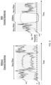
- FIG. 8 illustrates UE measurements with or without channel hardening, according to an embodiment.
- Two charts are shown, with and without CH.
- the curves 804 and 808 represent signal strengths and the curves 802 and 806 represent the standard deviation, STD, related to these signals.
- the vertical lines show the time instants in which the UE performs a new measurement (shown as either being "very often” as indicated by tightly-spaced lines or as "seldom” as indicated by lines that are more spread out).
- a given threshold indicated by the dashed horizontal line labeled "Std. Threshold”
- the UE is allowed to adjust the measurement periodicity from very often to seldom, as illustrated in the "With Channel Hardening" chart.
- TTT Time-To-Trigger
- Table 1 presents an example of possible STD thresholds and actions related to them. If STD is lower than a first threshold (here 0.3dBm), e.g., the channel fluctuations are low, then the L1 measurement periodicity may be set equal to 160ms. If the STD is higher than a second threshold (here 0.8dBm), e.g., the channel fluctuations are high, then the L1 measurement periodicity can be set equal to its default value, e.g., 20ms. For intermediary values of STD between the first and second threshold values, the L1 measurement periodicity can be set equal to 80ms. In embodiments, there may be more threshold values with correspondingly incremental actions taken. Additionally, in embodiments the action may involve a function (e.g. a step-wise and/or continuous function) of the STD value, e.g. the action may be to set the L1 measurement period as a function (e.g. a step-wise and/or continuous function) of STD.
- a first threshold here 0.3d
- Table 2 presents another example of possible STD thresholds and actions related to them.
- the UE shall scale the corresponding cell/beam's measurement property (e.g., periodicity/length of measurement, etc.) based on the scaling factor configured by the network for the hardened channel.
- the network configures different scaling factors per soft CH metric level defined. This is in principle similar to speed based scaling of mobility parameters in LTE. As shown below, if STD is lower than a first threshold (here 0.3dBm), e.g., the channel fluctuations are low, then the configured periodicity value is multiplied by 8. If the STD is higher than a second threshold (here 0.8dBm), e.g., the channel fluctuations are high, then the configured periodicity value is unchanged.
- a first threshold here 0.3dBm
- a second threshold here 0.8dBm
- the configured periodicity is multiplied by 4.
- the action may involve a function (e.g. a step-wise and/or continuous function) of the STD value, e.g. the action may be to set the L1 measurement period as a function (e.g. a step-wise and/or continuous function) of STD.
- the value of X i.e., number of samples recorded in the sliding window to compute the STD
- the STD may depend on the value of X. If there is a large window, a new sample may have a diminished impact on the STD. In this case, a high measurement period may not react fast enough to sudden drops in the signal quality, since it would take a longer time until there are enough measurements (due to the longer measurement period) to produce an important change in the STD.
- a network node e.g. BS
- BS network node
- the BS (or other network node) signals to the UE, e.g. via control channel such as by using a flag (e.g., ChHardFlag), whether the UE is permitted (or even required) to perform optimizations based on a CH parameter.
- ChHardFlag e.g., ChHardFlag
- the UE should follow some specific legacy measurement or reporting mode to just measure and report channel quality values as configured, and not to carry out any further action regarding channel hardening detection or measurement adaptation. This way, all the advanced operations/computations would be left to BS side and from UE side, it would be transparent.
- the BS may set ChHardFlag equal to TRUE, thereby permitting the UE to perform one or more of the embodiments disclosed herein.
- the BS (or other network node) signals to the UE whether the UE is permitted (or even required) to perform optimizations based on a CH parameter on a granular level such as per frequency/carrier/band, per cell, per beam or group of beams, or per reference signal.
- the BS may reduce SSB and CSI-RS transmissions if it knows that the UEs are set to measure them with a higher measurement periodicity. That may reduce interference and make the system leaner, as the network can take actions based on the UE reported periodicity, such as reducing SSBs and CSI-RS transmissions if UEs are set (based on configuration) to not measuring them. In other words, when the network knows that the UE is using longer periods because of CH, the network may also transmit some reference signals within these longer periods.
- the detection of CH and/or a CH parameter may also be reported to the network (such as to a network node e.g. a BS) so that the network can adjust the periodicity of reference signals used for channel quality measurements. For example, if network is aware that time domain CH is present, then the network may adjust the transmission periodicity of these RSs for that particular UE.
- the network such as to a network node e.g. a BS
- the BS collects statistics regarding CH detection and/or CH parameters.
- the BS may also, based on such statistics, adjust measurement parameters and indicate these adjusted parameters to one or more UEs via signaling.
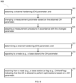
- FIG. 9 is a flow chart according to one or more embodiments.
- Process 900 is a method, performed by a UE.
- the method includes obtaining a channel hardening (CH) parameter (step 902); and changing (step 904) a measurement parameter based on the obtained CH parameter.
- the measurement parameter is for measuring a quantity such as a signal strength or power level based on the determined CH parameter (step 904).
- the obtaining a CH parameter comprises the UE determining the CH parameter itself, as described in more detail below.
- the method includes adapting (step 906) a measurement procedure in accordance with the changed parameter.
- the measurement procedure is a radio resource management (RRM) procedure which involves measuring a quantity.
- the measured quantity is a radio resource management (RRM) measurement including one or more of a channel quality indicator (CQI), a reference signal received power (RSRP), a reference signal received quality (RSRQ), and a carrier received signal strength indicator (RSSI).
- the measurement parameter is selected from the group consisting of a measurement period, a sample length, a length of coherent averaging, a measurement bandwidth, a set of reference signals, and a number of beams to average.
- obtaining the CH parameter comprises obtaining an indication that a CH condition is present and as a result of the CH condition being present, changing the measurement parameter. In some embodiments, this is achieved by determining that a CH condition is present and as a result of the CH condition being present, changing the measurement parameter. In some embodiments, determining that the CH condition is present comprises determining that the CH parameter is less than a first CH threshold.
- the method further includes, as a result of determining that the CH condition is present, periodically changing the measurement parameter for measuring the quantity based on the obtained CH parameter; in further embodiments, the method may include determining that the CH condition is not present and, as a result of determining that the CH condition is not present, ceasing to periodically change the measurement parameter for measuring the quantity based on the determined CH parameter.
- changing a measurement parameter for measuring the quantity based on the obtained CH parameter comprises determining that a CH condition is not present and as a result of the CH condition not being present, changing the measurement parameter. In some embodiments, determining that the CH condition is not present comprises determining that the CH parameter exceeds a second CH threshold.
- obtaining the CH parameter comprises determining a first CH parameter for a first frequency and/or carrier and/or band and a second CH parameter for a second frequency and/or carrier and/or band; and changing the measurement parameter for measuring the quantity based on the obtained CH parameter comprises changing the measurement parameter for measuring the quantity on the first frequency and/or carrier and/or band based on the determined first CH parameter and not changing the measurement parameter for measuring the quantity on the second frequency and/or carrier and/or band based on the determined second CH parameter.
- obtaining the CH parameter comprises determining a first CH parameter for a first cell and a second CH parameter for a second cell; and changing the measurement parameter for measuring the quantity based on the obtained parameter comprises changing the measurement parameter for measuring the quantity on the first cell and/or band based on the determined first CH parameter and not changing the measurement parameter for measuring the quantity on the second cell based on the determined second CH parameter.
- obtaining the CH parameter comprises determining a first CH parameter for a first beam and/or group of beams and a second CH parameter for a second beam and/or group of beams; and changing the measurement parameter for measuring the quantity based on the obtained CH parameter comprises changing the measurement parameter for measuring the quantity on the first beam and/or group of beams and/or band based on the determined first CH parameter and not changing the measurement parameter for measuring the quantity on the second beam and/or group of beams based on the determined second CH parameter.
- changing a measurement parameter for measuring the quantity based on the obtained CH parameter comprises increasing a measurement period because the CH parameter is less than a threshold.
- changing a measurement parameter for measuring the quantity based on the obtained CH parameter comprises decreasing a measurement period because the CH parameter exceeds a threshold.
- changing a measurement parameter for measuring the quantity based on the obtained CH parameter comprises decreasing a sample length for performing non-coherent averaging because the CH parameter is less than a threshold. In embodiments, changing a measurement parameter for measuring the quantity based on the obtained CH parameter comprises increasing a sample length for performing non-coherent averaging because the CH parameter exceeds a threshold. In some embodiments, changing a measurement parameter for measuring the quantity based on the obtained CH parameter comprises decreasing a length of coherent averaging because the CH parameter is less than a threshold.
- changing a measurement parameter for measuring the quantity based on the obtained CH parameter comprises increasing a length of coherent averaging because the CH parameter exceeds a threshold. In embodiments, changing a measurement parameter for measuring the quantity based on the obtained CH parameter comprises reducing a measurement bandwidth because the CH parameter is less than a threshold. In some embodiments, changing a measurement parameter for measuring the quantity based on the obtained CH parameter comprises increasing a measurement bandwidth because the CH parameter exceeds a threshold.
- changing a measurement parameter for measuring the quantity based on the obtained CH parameter comprises setting a reference signal parameter because the CH parameter is less than a threshold, such that the reference signal parameter indicates to only use secondary synchronization signals (SSSs) from a synchronization signal block (SSB), and not to use demodulation reference signals (DMRSs) from the SSB.
- SSSs secondary synchronization signals
- SSB synchronization signal block
- DMRSs demodulation reference signals
- changing a measurement parameter for measuring the quantity based on the obtained CH parameter comprises setting a reference signal parameter because the CH parameter is less than a threshold, such that the reference signal parameter indicates to only use reference signals from a synchronization signal block (SSB), and not to use channel state information reference signals (CSI-RSs).
- changing a measurement parameter for measuring the quantity based on the obtained CH parameter comprises reducing a set of beams for deriving cell quality because the CH parameter is less than a threshold.
- changing a measurement parameter for measuring the quantity based on the obtained CH parameter comprises increasing a set of beams for deriving cell quality because the CH parameter exceeds a threshold.
- the CH parameter is a binary value that indicates either the presence or absence of a CH condition; in other embodiments, the CH parameter is an analog value that indicates a degree of a CH condition.
- obtaining a channel hardening (CH) parameter comprises: recording a set of previous channel estimations in a sliding window; estimating a standard deviation from the recorded set; and assigning the CH parameter based on the estimated standard deviation.
- assigning the CH parameter based on the estimated standard deviation comprises assigning a parameter indicating the presence of a CH condition if the standard deviation is less than a first threshold (e.g., 0.8 dBm) and assigning a parameter indicating the absence of a CH condition if the standard deviation is greater than or equal to the first threshold (e.g., 0.8 dBm).
- assigning the CH parameter based on the estimated standard deviation comprises assigning a parameter indicating the presence of a strong CH condition if the standard deviation is less than a first threshold (e.g., 0.3 dBm), assigning a parameter indicating the presence of a weak CH condition if the standard deviation is between the first threshold and a second threshold (e.g., 0.8 dBm), and assigning a parameter indicating the absence of a CH condition if the standard deviation is greater than or equal to the second threshold (e.g., 0.8 dBm).
- a first threshold e.g., 0.3 dBm
- assigning a parameter indicating the presence of a weak CH condition if the standard deviation is between the first threshold and a second threshold (e.g., 0.8 dBm)
- assigning a parameter indicating the absence of a CH condition if the standard deviation is greater than or equal to the second threshold (e.g., 0.8 dBm).
- the method includes signaling to a network node (e.g., a base station) the CH parameter.
- the method further includes receiving from a network node (e.g., a base station) an indication (e.g., ChHardFlag) indicating that the UE is allowed to perform optimizations based on the CH parameter.
- an indication e.g., ChHardFlag
- the method comprises determining a channel hardening (CH) parameter (step 912); and signaling to a node (e.g., a base station) the CH parameter (step 914).
- CH channel hardening
- the method comprises receiving from a network node (e.g., a base station) an indication (e.g., ChHardFlag) indicating that the UE is allowed to perform optimizations based on a CH parameter (step 922).
- a network node e.g., a base station
- an indication e.g., ChHardFlag
- FIG. 10 is a flow chart according to one or more embodiments.
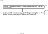
- Process 1000 is a method, performed by a node (e.g., a base station).
- the method includes obtaining a channel hardening (CH) parameter (step 1002).
- the CH parameter corresponds to a user equipment (UE) and is received from the user equipment (UE).
- the method further includes collecting statistics regarding CH conditions at the UE.
- the method optionally, further includes sending (step 1012) to the UE an indication (e.g., ChHardFlag) indicating that the UE is allowed to perform optimizations based on the CH parameter.
- the indication further indicates a granularity at which the UE is allowed to perform optimizations based on the CH parameter.
- the granularity is per frequency and/or per carrier and/or per band; the granularity is per cell; the granularity is per beam and/or group of beams; and/or the granularity is per reference signal.
- the method further includes adapting transmission of synchronization and reference signals based on the received CH parameter.
- adapting transmission of synchronization and reference signals based on the received CH parameter comprises reducing transmission of synchronization signal blocks (SSBs) and channel state information reference signals (CSI-RSs) based on the UE being in a CH condition.
- SSBs synchronization signal blocks
- CSI-RSs channel state information reference signals
- FIG. 11 is a diagram showing functional units of UE 1102, according to an embodiment.
- UE 1102 includes one or more of a determining unit 1104, a changing unit 1106, a signaling unit 1108, and a receiving unit 1110.
- the determining unit 1104 is configured to obtain a channel hardening (CH) parameter; and changing unit 1106 is configured to change a measurement parameter for measuring a quantity based on the obtained CH parameter.
- CH channel hardening
- the determining unit 1104 is further configured to determine a channel hardening (CH) parameter; and signaling unit 1108 is configured to signal to a node (e.g., a base station) the CH parameter.
- CH channel hardening
- the receiving unit 1110 is configured to receive from a network node (e.g., a base station) an indication (e.g., ChHardFlag) indicating that the UE is allowed to perform optimizations based on a CH parameter (step 922).
- a network node e.g., a base station
- an indication e.g., ChHardFlag
- FIG. 12 is a diagram showing functional units of network node 1202 (such as a BS e.g. eNB or gNB), according to an embodiment.
- Node 1202 includes one or more of a receiving unit 1204 and a sending unit 1206.
- the receiving unit 1204 is configured to receive from a user equipment (UE) a channel hardening (CH) parameter.
- UE user equipment
- CH channel hardening
- the sending unit 1206 is configured to send to a UE an indication (e.g., ChHardFlag) indicating that the UE is allowed to perform optimizations based on a CH parameter.
- an indication e.g., ChHardFlag
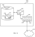
- FIG. 13 is a block diagram of UE 1102 and/or network node 1202, according to some embodiments.
- UE 1102 and/or network node 1202 may comprise: processing circuitry (PC) 1302, which may include one or more processors (P) 1355 (e.g., a general purpose microprocessor and/or one or more other processors, such as an application specific integrated circuit (ASIC), field-programmable gate arrays (FPGAs), and the like); a network interface 1348 comprising a transmitter (Tx) 1345 and a receiver (Rx) 1347 for enabling UE 1102 and/or network node 1202 to transmit data to and receive data from other nodes connected to a network 1310 (e.g., an Internet Protocol (IP) network) to which network interface 1348 is connected; and a local storage unit (a.k.a., "data storage system”) 1308, which may include one or more nonvolatile storage devices and/or one or more volatile storage devices.
- PC processing circuitry
- P processors
- CPP 1341 includes a computer readable medium (CRM) 1342 storing a computer program (CP) 1343 comprising computer readable instructions (CRI) 1344.
- CRM 1342 may be a non-transitory computer readable medium, such as, magnetic media (e.g., a hard disk), optical media, memory devices (e.g., random access memory, flash memory), and the like.
- the CRI 1344 of computer program 1343 is configured such that when executed by PC 1302, the CRI causes UE 1102 and/or network node 1202 to perform steps described herein (e.g., steps described herein with reference to the flow charts).
- UE 1102 and/or network node 1202 may be configured to perform steps described herein without the need for code. That is, for example, PC 1302 may consist merely of one or more ASICs. Hence, the features of the embodiments described herein may be implemented in hardware and/or software.
Claims (15)
- Procédé (900), mis en oeuvre par un équipement utilisateur, UE, (1102) le procédé comprenant :l'obtention (902) d'un paramètre de durcissement de canal, CH ;le changement (904) d'un paramètre de mesure en fonction du paramètre CH obtenu ; etl'adaptation (906) d'une procédure de mesure conformément au paramètre changé ;le fait de signaler le paramètre CH à un noeud de réseau (1202) ;la réception depuis le noeud de réseau (1202) d'une indication indiquant que l'UE (1102) est autorisé à mettre en oeuvre des optimisations de mesures en fonction du paramètre CH ;le procédé étant caractérisé en ce que l'indication indique une granularité à laquelle l'UE (1102) est autorisé à mettre en oeuvre des optimisations de mesures en fonction du paramètre CH.
- Procédé (900) selon la revendication 1, dans lequel la procédure de mesure est une mesure de gestion de ressources radio, RRM, qui implique la mesure d'une quantité comportant un ou plusieurs parmi un indicateur de qualité de canal, CQI, une puissance reçue de signal de référence, RSRP, une qualité reçue de signal de référence, RSRQ, et un indicateur de force de signal reçu, RSSI, de porteuse.
- Procédé (900) selon l'une quelconque des revendications 1 à 2, dans lequel le paramètre de mesure est choisi dans le groupe constitué par une période de mesure, une longueur d'échantillon, une longueur de moyennage cohérent, une largeur de bande de mesure, un ensemble de signaux de référence, et un nombre de faisceaux à moyenner.
- Procédé (900) selon l'une quelconque des revendications 1 à 3, dans lequel l'obtention du paramètre CH comprend l'obtention d'une indication indiquant qu'une condition CH est présente et en conséquence de la condition CH étant présente, le changement du paramètre de mesure.
- Procédé (900) selon la revendication 4, dans lequel l'obtention de l'indication indiquant que la condition CH est présente comprend la détermination (912) que le paramètre CH est inférieur à un premier seuil CH.
- Procédé (900) selon l'une quelconque des revendications 4 à 5, comprenant en outre, en conséquence de l'obtention de l'indication indiquant que la condition CH est présente, le changement périodique du paramètre de mesure en fonction du paramètre CH obtenu.
- Procédé (900) selon la revendication 6, comprenant en outre la détermination que la condition CH n'est pas présente et, en conséquence de la détermination que la condition CH n'est pas présente, l'arrêt de changement périodique du paramètre de mesure en fonction du paramètre CH obtenu.
- Procédé (900) selon l'une quelconque des revendications 1 à 7, dans lequel le changement d'un paramètre de mesure en fonction du paramètre CH obtenu comprend l'augmentation d'une période de mesure parce que le paramètre CH est inférieur à un seuil.
- Procédé (900) selon l'une quelconque des revendications 1 à 8, dans lequel le changement d'un paramètre de mesure en fonction du paramètre CH obtenu comprend la diminution d'une période de mesure parce que le paramètre CH dépasse un seuil.
- Procédé (1000) mis en oeuvre par un noeud de réseau (1202), le procédé comprenant :la réception (1002) d'un paramètre de durcissement de canal, CH, correspondant à un équipement utilisateur, UE (1102) ; etl'envoi (1012) à l'UE (1102) d'une indication indiquant que l'UE (1102) est autorisé à mettre en oeuvre des optimisations de mesures en fonction du paramètre CH obtenule procédé étant caractérisé en ce que l'indication indique une granularité à laquelle l'UE (1102) est autorisé à mettre en oeuvre des optimisations de mesures en fonction du paramètre CH.
- Procédé (1000) selon la revendication 10, comprenant en outre la collecte de statistiques concernant des conditions CH au niveau de l'UE.
- Procédé (1000) selon l'une quelconque des revendications 10 à 11, comprenant en outre l'adaptation de transmission de signaux de synchronisation et de référence en fonction du paramètre CH obtenu.
- Procédé (1000) selon la revendication 12, dans lequel l'adaptation de transmission de signaux de synchronisation et de référence en fonction du paramètre CH obtenu comprend la réduction de transmission de blocs de signal de synchronisation, SSB, et de signaux de référence d'informations d'état de canal, CSI-RS, en fonction de l'UE étant dans une condition CH.
- Équipement utilisateur, UE, comprenant :un moyen permettant d'obtenir un paramètre de durcissement de canal, CH ;un moyen permettant de changer un paramètre de mesure en fonction du paramètre CH obtenu ; etun moyen permettant d'adapter une procédure de mesure conformément au paramètre changéun moyen permettant de signaler le paramètre CH à un noeud de réseau (1202) ;un moyen permettant de recevoir depuis le noeud de réseau (1202) une indication indiquant que l'UE (1102) est autorisé à mettre en oeuvre des optimisations de mesures en fonction du paramètre CH ;l'UE (1102) étant caractérisé en ce que l'indication indique une granularité à laquelle l'UE (1102) est autorisé à mettre en oeuvre des optimisations de mesures en fonction du paramètre CH.
- Noeud de réseau (1202) comprenant :un moyen permettant de recevoir un paramètre de durcissement de canal, CH, correspondant à un équipement utilisateur, UE, (1102) ; etun moyen permettant d'envoyer à l'UE (1102) une indication indiquant que l'UE (1102) est autorisé à mettre en oeuvre des optimisations de mesures en fonction du paramètre CH obtenu ;le noeud de réseau (1202) étant caractérisé en ce que l'indication indique une granularité à laquelle l'UE (1102) est autorisé à mettre en oeuvre des optimisations de mesures en fonction du paramètre CH.
Applications Claiming Priority (2)
| Application Number | Priority Date | Filing Date | Title |
|---|---|---|---|
| US201862757499P | 2018-11-08 | 2018-11-08 | |
| PCT/EP2019/080524 WO2020094783A1 (fr) | 2018-11-08 | 2019-11-07 | Adaptation de mesurage basée sur un renforcement de canal |
Publications (2)
| Publication Number | Publication Date |
|---|---|
| EP3878200A1 EP3878200A1 (fr) | 2021-09-15 |
| EP3878200B1 true EP3878200B1 (fr) | 2023-09-06 |
Family
ID=68503124
Family Applications (1)
| Application Number | Title | Priority Date | Filing Date |
|---|---|---|---|
| EP19801292.4A Active EP3878200B1 (fr) | 2018-11-08 | 2019-11-07 | Adaptation de mesurage basée sur un renforcement de canal |
Country Status (3)
| Country | Link |
|---|---|
| US (1) | US20210392526A1 (fr) |
| EP (1) | EP3878200B1 (fr) |
| WO (1) | WO2020094783A1 (fr) |
Families Citing this family (3)
| Publication number | Priority date | Publication date | Assignee | Title |
|---|---|---|---|---|
| US11665600B2 (en) * | 2019-12-19 | 2023-05-30 | Qualcomm Incorporated | Neighbor cell layer 1 metrics for fast cell change |
| CN114545405B (zh) * | 2022-02-24 | 2023-05-02 | 电子科技大学 | 一种基于神经网络的实波束扫描雷达角超分辨方法 |
| CN117397340A (zh) * | 2022-05-11 | 2024-01-12 | 北京小米移动软件有限公司 | 相干带宽的测量方法和装置 |
Family Cites Families (16)
| Publication number | Priority date | Publication date | Assignee | Title |
|---|---|---|---|---|
| US9252823B2 (en) * | 2013-08-06 | 2016-02-02 | Purdue Research Foundation | Phase compensation filtering for multipath wireless systems |
| US9647734B2 (en) * | 2013-11-14 | 2017-05-09 | Mediatek Singapore Pte. Ltd. | Large-scale fading coefficient estimation in wireless massive MIMO systems |
| US20180175992A1 (en) * | 2015-06-17 | 2018-06-21 | Telefonaktiebolaget Lm Ericsson (Publ) | A Wireless Device, A Radio Network Node, And Methods Therein |
| EP3412075A1 (fr) * | 2016-02-02 | 2018-12-12 | Telefonaktiebolaget LM Ericsson (publ) | Dispositif sans fil, noeud de réseau et procédés exécutés par ceux-ci pour communiquer les uns avec les autres |
| WO2017133775A1 (fr) * | 2016-02-04 | 2017-08-10 | Telefonaktiebolaget Lm Ericsson (Publ) | Rapport de qualité de canal radio |
| US11064438B2 (en) * | 2016-03-07 | 2021-07-13 | Telefonaktiebolaget Lm Ericsson (Publ) | Reliable communication to energy-detection receivers |
| US10630410B2 (en) * | 2016-05-13 | 2020-04-21 | Telefonaktiebolaget Lm Ericsson (Publ) | Network architecture, methods, and devices for a wireless communications network |
| US10367677B2 (en) * | 2016-05-13 | 2019-07-30 | Telefonaktiebolaget Lm Ericsson (Publ) | Network architecture, methods, and devices for a wireless communications network |
| US11133907B2 (en) * | 2017-09-27 | 2021-09-28 | Telefonaktiebolaget Lm Ericsson (Publ) | Downlink pilot assignment in massive MIMO |
| WO2019099024A1 (fr) * | 2017-11-17 | 2019-05-23 | Nokia Technologies Oy | Procédés et appareils pour un livre de codes à quantification multiple pour une rétroaction d'informations d'état de canal explicite dans une nouvelle radio |
| KR102072285B1 (ko) * | 2018-01-23 | 2020-02-03 | 한국과학기술원 | 대역 내 무선 백홀을 이용한 다계층 이종망의 상하향 링크 간섭제어 방법 및 장치 |
| WO2019196121A1 (fr) * | 2018-04-13 | 2019-10-17 | Nokia Shanghai Bell Co., Ltd. | Compression d'informations d'emplacement de prise pour une rétroaction d'informations d'état de canal explicite dans le domaine temporel dans une nouvelle radio |
| WO2019218317A1 (fr) * | 2018-05-17 | 2019-11-21 | Nokia Shanghai Bell Co., Ltd. | Renforcement de canal basé sur une valeur propre, et rétroaction explicite |
| WO2020030848A1 (fr) * | 2018-08-09 | 2020-02-13 | Nokia Technologies Oy | Exploitation de corrélation d'antenne de récepteur dans un procédé de rétroaction de csi fondé sur la compression temporelle |
| US20210234574A1 (en) * | 2018-08-30 | 2021-07-29 | Nokia Technologies Oy | Frequency time domain channel hardening and overhead reduction |
| WO2020075125A1 (fr) * | 2018-10-12 | 2020-04-16 | Indian Institute Of Technology, Delhi | Procédé de transmission pour un système de communication sans fil et appareil associé |
-
2019
- 2019-11-07 US US17/291,024 patent/US20210392526A1/en active Pending
- 2019-11-07 EP EP19801292.4A patent/EP3878200B1/fr active Active
- 2019-11-07 WO PCT/EP2019/080524 patent/WO2020094783A1/fr unknown
Also Published As
| Publication number | Publication date |
|---|---|
| US20210392526A1 (en) | 2021-12-16 |
| WO2020094783A1 (fr) | 2020-05-14 |
| EP3878200A1 (fr) | 2021-09-15 |
Similar Documents
| Publication | Publication Date | Title |
|---|---|---|
| US10993134B2 (en) | Radio resource measurement method, radio resource selection method, and apparatus | |
| US10499267B2 (en) | Configuration of mobility management measurement method | |
| RU2621678C2 (ru) | Способы и устройства, относящиеся к эффективным измерениям со сниженными помехами | |
| US9585104B2 (en) | Performing inter-frequency measurements on carriers with overlapping bandwidths | |
| EP3400734B1 (fr) | Procédés d'adaptation de période de mesure d'ue aux conditions radioélectriques | |
| EP3414854B1 (fr) | Commande de qualité de mesure d'occupation de canal | |
| EP3878200B1 (fr) | Adaptation de mesurage basée sur un renforcement de canal | |
| US9900867B2 (en) | User equipment and a method for transmitting sounding reference signals | |
| EP3607668B1 (fr) | Dérivation de qualité de cellule sur la base de mesures de faisceau filtrées | |
| US10091805B2 (en) | Method in a network and network node for co-scheduling in a network | |
| EP3111692B1 (fr) | Équipement utilisateur, support lisible par ordinateur et procédé pour déterminer la mobilité de l'équipement utilisateur dans un réseau d'évolution à long terme | |
| CN108353328B (zh) | 尤其在扩展覆盖下的自适应小区搜索 | |
| RU2719280C1 (ru) | Смена соты в системе беспроводной связи | |
| WO2023165708A1 (fr) | Commande de balayage de faisceau de réception pour le maintien d'une connexion de faisceau |
Legal Events
| Date | Code | Title | Description |
|---|---|---|---|
| STAA | Information on the status of an ep patent application or granted ep patent |
Free format text: STATUS: UNKNOWN |
|
| STAA | Information on the status of an ep patent application or granted ep patent |
Free format text: STATUS: THE INTERNATIONAL PUBLICATION HAS BEEN MADE |
|
| PUAI | Public reference made under article 153(3) epc to a published international application that has entered the european phase |
Free format text: ORIGINAL CODE: 0009012 |
|
| STAA | Information on the status of an ep patent application or granted ep patent |
Free format text: STATUS: REQUEST FOR EXAMINATION WAS MADE |
|
| 17P | Request for examination filed |
Effective date: 20210603 |
|
| AK | Designated contracting states |
Kind code of ref document: A1 Designated state(s): AL AT BE BG CH CY CZ DE DK EE ES FI FR GB GR HR HU IE IS IT LI LT LU LV MC MK MT NL NO PL PT RO RS SE SI SK SM TR |
|
| DAV | Request for validation of the european patent (deleted) | ||
| DAX | Request for extension of the european patent (deleted) | ||
| GRAP | Despatch of communication of intention to grant a patent |
Free format text: ORIGINAL CODE: EPIDOSNIGR1 |
|
| STAA | Information on the status of an ep patent application or granted ep patent |
Free format text: STATUS: GRANT OF PATENT IS INTENDED |
|
| INTG | Intention to grant announced |
Effective date: 20230328 |
|
| GRAS | Grant fee paid |
Free format text: ORIGINAL CODE: EPIDOSNIGR3 |
|
| GRAA | (expected) grant |
Free format text: ORIGINAL CODE: 0009210 |
|
| STAA | Information on the status of an ep patent application or granted ep patent |
Free format text: STATUS: THE PATENT HAS BEEN GRANTED |
|
| AK | Designated contracting states |
Kind code of ref document: B1 Designated state(s): AL AT BE BG CH CY CZ DE DK EE ES FI FR GB GR HR HU IE IS IT LI LT LU LV MC MK MT NL NO PL PT RO RS SE SI SK SM TR |
|
| REG | Reference to a national code |
Ref country code: GB Ref legal event code: FG4D |
|
| REG | Reference to a national code |
Ref country code: CH Ref legal event code: EP |
|
| REG | Reference to a national code |
Ref country code: IE Ref legal event code: FG4D |
|
| REG | Reference to a national code |
Ref country code: DE Ref legal event code: R096 Ref document number: 602019036954 Country of ref document: DE |
|
| REG | Reference to a national code |
Ref country code: LT Ref legal event code: MG9D |
|
| REG | Reference to a national code |
Ref country code: NL Ref legal event code: MP Effective date: 20230906 |
|
| PG25 | Lapsed in a contracting state [announced via postgrant information from national office to epo] |
Ref country code: GR Free format text: LAPSE BECAUSE OF FAILURE TO SUBMIT A TRANSLATION OF THE DESCRIPTION OR TO PAY THE FEE WITHIN THE PRESCRIBED TIME-LIMIT Effective date: 20231207 |
|
| PG25 | Lapsed in a contracting state [announced via postgrant information from national office to epo] |
Ref country code: SE Free format text: LAPSE BECAUSE OF FAILURE TO SUBMIT A TRANSLATION OF THE DESCRIPTION OR TO PAY THE FEE WITHIN THE PRESCRIBED TIME-LIMIT Effective date: 20230906 Ref country code: RS Free format text: LAPSE BECAUSE OF FAILURE TO SUBMIT A TRANSLATION OF THE DESCRIPTION OR TO PAY THE FEE WITHIN THE PRESCRIBED TIME-LIMIT Effective date: 20230906 Ref country code: NO Free format text: LAPSE BECAUSE OF FAILURE TO SUBMIT A TRANSLATION OF THE DESCRIPTION OR TO PAY THE FEE WITHIN THE PRESCRIBED TIME-LIMIT Effective date: 20231206 Ref country code: LV Free format text: LAPSE BECAUSE OF FAILURE TO SUBMIT A TRANSLATION OF THE DESCRIPTION OR TO PAY THE FEE WITHIN THE PRESCRIBED TIME-LIMIT Effective date: 20230906 Ref country code: LT Free format text: LAPSE BECAUSE OF FAILURE TO SUBMIT A TRANSLATION OF THE DESCRIPTION OR TO PAY THE FEE WITHIN THE PRESCRIBED TIME-LIMIT Effective date: 20230906 Ref country code: HR Free format text: LAPSE BECAUSE OF FAILURE TO SUBMIT A TRANSLATION OF THE DESCRIPTION OR TO PAY THE FEE WITHIN THE PRESCRIBED TIME-LIMIT Effective date: 20230906 Ref country code: GR Free format text: LAPSE BECAUSE OF FAILURE TO SUBMIT A TRANSLATION OF THE DESCRIPTION OR TO PAY THE FEE WITHIN THE PRESCRIBED TIME-LIMIT Effective date: 20231207 Ref country code: FI Free format text: LAPSE BECAUSE OF FAILURE TO SUBMIT A TRANSLATION OF THE DESCRIPTION OR TO PAY THE FEE WITHIN THE PRESCRIBED TIME-LIMIT Effective date: 20230906 |
|
| REG | Reference to a national code |
Ref country code: AT Ref legal event code: MK05 Ref document number: 1610182 Country of ref document: AT Kind code of ref document: T Effective date: 20230906 |
|
| PG25 | Lapsed in a contracting state [announced via postgrant information from national office to epo] |
Ref country code: NL Free format text: LAPSE BECAUSE OF FAILURE TO SUBMIT A TRANSLATION OF THE DESCRIPTION OR TO PAY THE FEE WITHIN THE PRESCRIBED TIME-LIMIT Effective date: 20230906 |
|
| PG25 | Lapsed in a contracting state [announced via postgrant information from national office to epo] |
Ref country code: IS Free format text: LAPSE BECAUSE OF FAILURE TO SUBMIT A TRANSLATION OF THE DESCRIPTION OR TO PAY THE FEE WITHIN THE PRESCRIBED TIME-LIMIT Effective date: 20240106 |