EP3877663B1 - Channel fastener having tapering support body - Google Patents
Channel fastener having tapering support body Download PDFInfo
- Publication number
- EP3877663B1 EP3877663B1 EP19829343.3A EP19829343A EP3877663B1 EP 3877663 B1 EP3877663 B1 EP 3877663B1 EP 19829343 A EP19829343 A EP 19829343A EP 3877663 B1 EP3877663 B1 EP 3877663B1
- Authority
- EP
- European Patent Office
- Prior art keywords
- flanges
- fastener
- channel
- anchoring element
- support
- Prior art date
- Legal status (The legal status is an assumption and is not a legal conclusion. Google has not performed a legal analysis and makes no representation as to the accuracy of the status listed.)
- Active
Links
- 238000004873 anchoring Methods 0.000 claims description 139
- 230000004308 accommodation Effects 0.000 claims description 27
- 230000014759 maintenance of location Effects 0.000 claims description 26
- 239000002184 metal Substances 0.000 claims description 14
- 230000000903 blocking effect Effects 0.000 claims description 10
- 230000008878 coupling Effects 0.000 claims description 10
- 238000010168 coupling process Methods 0.000 claims description 10
- 238000005859 coupling reaction Methods 0.000 claims description 10
- 210000002105 tongue Anatomy 0.000 claims description 6
- 239000012815 thermoplastic material Substances 0.000 claims description 5
- 239000013013 elastic material Substances 0.000 claims description 4
- 238000000034 method Methods 0.000 claims description 3
- 230000000284 resting effect Effects 0.000 claims description 3
- 239000000463 material Substances 0.000 description 5
- 239000004033 plastic Substances 0.000 description 4
- 230000006835 compression Effects 0.000 description 3
- 238000007906 compression Methods 0.000 description 3
- 238000004519 manufacturing process Methods 0.000 description 3
- 238000009740 moulding (composite fabrication) Methods 0.000 description 3
- 238000001746 injection moulding Methods 0.000 description 2
- 229910000831 Steel Inorganic materials 0.000 description 1
- 238000005520 cutting process Methods 0.000 description 1
- 238000003780 insertion Methods 0.000 description 1
- 230000037431 insertion Effects 0.000 description 1
- 238000009434 installation Methods 0.000 description 1
- 238000004080 punching Methods 0.000 description 1
- 230000000717 retained effect Effects 0.000 description 1
- 239000010959 steel Substances 0.000 description 1
- 229920001169 thermoplastic Polymers 0.000 description 1
- 239000004416 thermosoftening plastic Substances 0.000 description 1
Images


Classifications
-
- F—MECHANICAL ENGINEERING; LIGHTING; HEATING; WEAPONS; BLASTING
- F16—ENGINEERING ELEMENTS AND UNITS; GENERAL MEASURES FOR PRODUCING AND MAINTAINING EFFECTIVE FUNCTIONING OF MACHINES OR INSTALLATIONS; THERMAL INSULATION IN GENERAL
- F16B—DEVICES FOR FASTENING OR SECURING CONSTRUCTIONAL ELEMENTS OR MACHINE PARTS TOGETHER, e.g. NAILS, BOLTS, CIRCLIPS, CLAMPS, CLIPS OR WEDGES; JOINTS OR JOINTING
- F16B37/00—Nuts or like thread-engaging members
- F16B37/04—Devices for fastening nuts to surfaces, e.g. sheets, plates
- F16B37/045—Devices for fastening nuts to surfaces, e.g. sheets, plates specially adapted for fastening in channels, e.g. sliding bolts, channel nuts
- F16B37/046—Devices for fastening nuts to surfaces, e.g. sheets, plates specially adapted for fastening in channels, e.g. sliding bolts, channel nuts with resilient means for urging the nut inside the channel
-
- F—MECHANICAL ENGINEERING; LIGHTING; HEATING; WEAPONS; BLASTING
- F16—ENGINEERING ELEMENTS AND UNITS; GENERAL MEASURES FOR PRODUCING AND MAINTAINING EFFECTIVE FUNCTIONING OF MACHINES OR INSTALLATIONS; THERMAL INSULATION IN GENERAL
- F16B—DEVICES FOR FASTENING OR SECURING CONSTRUCTIONAL ELEMENTS OR MACHINE PARTS TOGETHER, e.g. NAILS, BOLTS, CIRCLIPS, CLAMPS, CLIPS OR WEDGES; JOINTS OR JOINTING
- F16B37/00—Nuts or like thread-engaging members
- F16B37/04—Devices for fastening nuts to surfaces, e.g. sheets, plates
- F16B37/041—Releasable devices
- F16B37/042—Releasable devices locking by rotation
-
- F—MECHANICAL ENGINEERING; LIGHTING; HEATING; WEAPONS; BLASTING
- F16—ENGINEERING ELEMENTS AND UNITS; GENERAL MEASURES FOR PRODUCING AND MAINTAINING EFFECTIVE FUNCTIONING OF MACHINES OR INSTALLATIONS; THERMAL INSULATION IN GENERAL
- F16B—DEVICES FOR FASTENING OR SECURING CONSTRUCTIONAL ELEMENTS OR MACHINE PARTS TOGETHER, e.g. NAILS, BOLTS, CIRCLIPS, CLAMPS, CLIPS OR WEDGES; JOINTS OR JOINTING
- F16B39/00—Locking of screws, bolts or nuts
- F16B39/22—Locking of screws, bolts or nuts in which the locking takes place during screwing down or tightening
- F16B39/28—Locking of screws, bolts or nuts in which the locking takes place during screwing down or tightening by special members on, or shape of, the nut or bolt
- F16B39/282—Locking by means of special shape of work-engaging surfaces, e.g. notched or toothed nuts
Definitions
- the invention relates to a channel fastener for fastening an object to an elongate channel element, wherein said channel element has a bottom, an upper side opposite the bottom and lateral walls that interconnect the upper side and the bottom, wherein the upper side includes flanges that extend from the lateral walls towards each other and a longitudinal slot defined between the flanges and having a slot width,
- Such a channel fastener is typically used with channel elements, in the technical field concerned often called mounting rails.
- a particular type of mounting rail that the channel fasteners are used with is known in the field as a "strut rail", which is a mounting rail having generally a C-shaped cross section, wherein the flanges are folded inwardly such that the edges of the flanges are facing the bottom of the rail.
- the channel fasteners can also be used with normal C-shaped rails, having flanges that extend with their edges towards each other, or other channel type profiles that have flanges defining a slot between them.
- the US Design Patent 494,887 shows a channel fastener for use with mounting rails.
- This known channel fastener is an assembly of a metal washer element, a plastic support and a metal anchoring element.
- the metal anchoring element is formed as an oblong nut with a threaded bore in the centre. On an upper side of the oblong nut grooves are formed which extend in the transverse direction. This is typical for channel fasteners which are used in combination with strut rails. The edges of the respective flanges of the strut rail are in a mounted state received in the respective grooves on the upper side of the nut.
- the plastic support is an integrally formed part including a cage which carries the metal anchoring element, and furthermore including a head portion that is connected to the washer. Two opposite spring elements surrounding the washer element are connected to the head portion and are adapted to engage flanges of the channel element.
- the oblong anchoring element of the fastener can be aligned with the longitudinal slot of a channel element and subsequently the anchoring element can be inserted through the longitudinal slot into the channel element. Subsequently after turning of the fastener, the anchoring element extends at an angle relative to the longitudinal slot, such that the flanges of the channel element are located in accommodation spaces between the washer element and longitudinal end portions of the anchoring element.
- the channel fastener In this position the spring elements engage the flanges of the channel element and pull the fastener upwards such that the longitudinal end portions of the anchoring element are pulled in engagement with the flanges of the channel element.
- the channel fastener In this state the channel fastener is in a preliminary mounting state, in which it is held stationary on the channel element by the spring force of the spring elements and can still be readily moved along the channel element towards its desired position.
- the anchoring element and the washer element can be tensioned towards each other by means of a male fastening element such as a threaded rod screwed in the oblong anchoring element and a nut engaging the washer element.
- the flanges of the channel element are thereby clamped between the longitudinal end portions of the anchoring element and the washer element in order to fix the fastener to the channel element.
- a channel fastener for fastening an object to an elongate channel element, wherein said channel element has a bottom, an upper side opposite the bottom and lateral walls that interconnect the upper side and the bottom, wherein the upper side includes flanges that extend from the lateral walls towards each other and a longitudinal slot defined between the flanges and having a slot width,
- the support of the channel fastener according to the invention is made of an elastic material, preferably a thermoplastic material.
- the head portion and the connecting legs of the support form a tapering width from the head portion towards the bottom portion of the support. At least the head portion at the location where it adjoins the legs has an initial width that exceeds the width of the longitudinal slot of the channel element, such that when the anchoring element is aligned with the longitudinal slot of the channel element and inserted through the slot in the channel element, the legs and/or the head portion rub against the flanges and are/is elastically compressed such that the fastener can be held clamped between the flanges in a first preliminary mounting state.
- the user can position the fasteners according to the invention roughly on the channel element using the first preliminary mounting state before turning the fastener to a second preliminary mounting state. Both in the first and second preliminary mounting state the fastener can be shifted along the channel element.
- the support is made of a thermoplastic material.
- thermoplastic support will be made by an injection moulding process.
- the head portion of the support comprises a main body having a central passage from the washer element towards the anchoring element, wherein two longitudinal slits extend from the central passage in the main body, said longitudinal slits being opened wide in an unloaded state and being closed in the first preliminary mounting state.
- the central opening allows a male fastener, such as a threaded rod, to be passed through the main body to extend from the anchoring element to the washer element.
- a male fastener such as a threaded rod
- the slits are closed by the compression force provided by the flanges in cooperation with the tapering width form of the head and the legs of the support.
- the main body is turned to a second preliminary mounting state, it will not rub against the flanges anymore and the slits will open again by the elasticity of the main body.
- the support includes one or more spring members associated with the head portion of the support, wherein said spring members force the bottom portion and the anchoring element towards the inner side of the flanges of the channel element in a second preliminary mounting state in which the flanges are located in the accommodation spaces.
- the spring elements provide a holding force to keep the channel fastener in position on the channel element, in the second preliminary mounting state.
- the spring members extend from the head portion of the support element into the accommodation space, such that when the fastener is rotated in the channel element towards the second preliminary mounting state, the spring members will be deformed and tensioned by the flanges of the channel element.
- the spring members may be associated with the bottom portion of the support and resiliently support the anchoring element from below, such that when the fastener is rotated in the channel element towards the second preliminary mounting state, the spring members will be deformed and tensioned by the anchoring element which is forced towards the bottom portion by the flanges of the channel element.
- the anchoring element is thus resiliently held against the inner side of the flanges in the second preliminary mounting state.
- a problem of the known channel fastener of USD 494,887 is that the force with which the anchoring element is forced in engagement with the flanges in the preliminary mounting state depends on the thickness or height of the anchoring element, while in practise the thickness or height of the anchoring element can vary considerably, for example due to manufacturing tolerances.
- the force also determines how well the fastener is maintained in position on the channel element, but also determines how easy the fastener can be moved towards the desired position along the channel element in the preliminary mounting state, in which the flanges of the channel element are located in the accommodation spaces of the fastener.
- This problem comes forward even more when the fastener is used with a strut rail and the anchoring element has grooves. Often the downwardly pointing edges of the flanges of the strut rail are provided with notches or are serrated. Also the grooves in the anchoring element may have notches which engage with the notches or serrations of the flange edges.
- the bottom portion comprises a bottom plate supporting the anchoring element and upstanding wall members extending upwardly from the bottom plate, wherein the upstanding wall members includes at least a longitudinal wall portion that extends at the longitudinal end portions of the anchoring element along a side of the anchoring element having the largest length, and wherein the upstanding wall portions have a height that exceeds the thickness of the anchoring element, such that when the anchoring element is in engagement with the bottom plate, an upper edge of the upstanding wall is located above the anchoring element and such that when the fastener is in the position wherein the flanges of the channel element are located in the accommodation spaces, the upper edge of the upstanding wall portions engage the inner side of the flanges in said second preliminary mounting state.
- An advantage of the one or more upstanding wall portions engaging the inner side of the flanges is that it does not depend on the thickness of the anchoring element how easy the fastener can be slid along the channel element.
- the dimensional relation between the upstanding wall portion and the spring members can be well defined in the design of the support. Therefore, and also due the flexible nature of the upstanding wall portion the channel fastener can provide a fairly constant and predefined holding force by the support itself, independent of the anchoring element the support is assembled with. The force needed to overcome the friction to move the fastener along the channel element is thus also constant and predetermined.
- the upstanding wall members may be located at two diagonally opposite corners of the oblong anchoring element. In this way each flange of the channel element engages only one upstanding wall portion. Thereby the resistance against movement of the channel fastener along the channel element can be well defined.
- the wall members furthermore comprise a transversal wall portion extending at an angle, preferably perpendicular, to the longitudinal wall portion, and forming a corner piece with the corresponding longitudinal wall portion.
- the transversal wall portion provides rigidity to the wall member, and also provides a locking means to retain the anchoring element on the bottom portion of the support in the longitudinal direction.
- the spring members are formed as tongues which extend obliquely from the head portion towards the anchoring element.
- a problem that may occur with the known channel fastener of USD 494,887 is that when it is mounted on a channel element and secured by a male fastening element, e.g. a threaded rod, and a cooperating nut, it may in some occasions be necessary to release the nut so as to be able to move the channel fastener along the channel element or rail.
- releasing the nut means that a rotational force is applied on the assembly of the channel fastener and the male fastening element, which may cause the channel fastener to be rotated out of the preliminary mounting state in which the flanges are located in the accommodation spaces. Thereby the fastener may be unintentionally loosened and displaced or even removed from the channel element.
- a blocking finger is formed on an end of at least one of the spring members, wherein said blocking finger extends in the second preliminary mounting state beyond the edge of at least one of the flanges and a side wall of the channel element, so as to block unintentional rotation of the fastener from the second preliminary mounting state.
- the blocking finger prevents that the entire channel fastener starts to rotate due to rotational forces applied to the fastener, e.g. when a nut is loosened on a threaded rod which is connected with the channel fastener. If the installing person wants to remove the channel fastener altogether, the flexibility of the spring members allows that the installer forces the blocking fingers over the edge of the flanges and lateral wall of the channel element again by lifting the spring members. However, if the spring members are not "helped" they are sturdy enough to keep the channel fastener in the preliminary mounting state on the channel element.
- the support includes one or more resilient retention fingers having a proximal end connected to the head portion and a distal end located near or in contact with the anchoring element, so as to retain the anchoring element on the bottom portion of the support.
- the retention fingers allow that anchoring elements having varying thicknesses can be assembled with the same support whilst the anchoring element is securely retained on the bottom portion by the retention fingers.
- the retention fingers are adapted to allow that the anchoring element is moved towards the washer element when the washer element and the anchoring element are tightened together by a male fastening element, possibly in cooperation with a nut. Thereto the retention fingers are resiliently deformable.
- the retention fingers extend from the main body obliquely towards the upper side of the anchoring element and are adapted to retain the anchoring element on a bottom plate of the support in an unmounted state.
- the oblique position of the retention fingers facilitates their deformation for allowing the anchoring element to move towards the washer element.
- the one or more retention fingers extend from the head portion downward and in transverse direction of the nut. This arrangement of the retention fingers prevents that the retention fingers interfere with the rotation of the fastener on the channel element to a preliminary mounting state in which the flanges of the channel element are received in the accommodation spaces of the channel fastener.
- the retention fingers are arranged in pairs, wherein, preferably the retention fingers of one pair together generally form a V-shape.
- the support includes two pairs of retention fingers, one on each side of the body adjacent the accommodation spaces of the channel fastener.
- the bottom portion comprises a bottom plate supporting the anchoring element and the retention fingers push the anchoring element against the bottom plate.
- the invention also relates to a combination of a fastener according to any aspect of the invention as described in the above and a channel element having a bottom, an upper side opposite the bottom and lateral walls that interconnect the upper side and the bottom, wherein the upper side includes flanges that extend from the lateral walls towards each other and a longitudinal slot defined between the flanges and having a slot width, wherein the channel element is of the so called "strut rail" type, i.e. the channel element has inwardly folded flanges, wherein the flanges have edges that are facing the bottom of the channel element.
- edge of the respective flanges are serrated.
- the invention also relates to a method for assembling a fastener according to any aspect of the invention as described in the above to a channel element, wherein the channel fastener is mounted in a first preliminary state and a second preliminary state on the channel element before it is finally secured to the channel element.
- the present invention relates to a channel fastener adapted to be mounted on a channel element.
- a channel element is in practice also called a mounting rail.
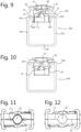
- FIG. 9 such a channel element or mounting rail is visible in cross section, perspective view and top elevation view, respectively.
- the mounting rail indicated by reference numeral 100 in general has a bottom 101, an upper side 102 opposite the bottom 101 and lateral walls 103 that interconnect the upper side 102 and the bottom 101.
- the upper side 102 of the channel element includes flanges 104 that extend from the lateral walls 103 towards each other and includes a longitudinal slot 106 defined between the flanges 104.
- the longitudinal slot 106 has a slot width w s .
- the channel element 100 shown here is specifically called a "strut rail" in the technical field concerned.
- Such a strut rail has the characteristic that the flanges 104 are folded inwardly such that the edges 105 of the flanges 104 are pointing towards the bottom 101 of the channel element 100. It is noted that the invention will be explained in combination with a strut rail, which is a preferred channel element, but that a channel fastener according to the invention may also be used in combination with other channel elements, e.g. having a regular C-shaped cross section.
- FIGs. 1 - 3 a possible embodiment of a channel fastener according to the invention is shown and indicated by reference numeral 1.
- the channel fastener 1 is an assembled part which generally comprises a washer element 2, an anchoring element 3, and a support 4.
- the washer element 2 is preferably made of metal, but may in some occasions also be made of a suitable plastic material, such as POM.
- the anchoring element 3 is made of metal.
- the support 4 is made of an elastic material which interconnects the washer element 2 and the anchoring element 3.
- a suitable material for manufacturing the support element 4 is a thermoplastic material.
- the support 4 is in practice made from the thermoplastic material by an injection moulding process.
- the metal washer 2 and the metal anchoring element 3 are made by suitable cutting, punching and forming processes, preferably out of steel strip or sheet material.
- the anchoring element 3 may be formed as an elongate nut having a central threaded bore 5, adapted to cooperate with a shaft of a male fastening element such as a threaded rod or a bolt.
- the anchoring element 3 has a width w a that is smaller than the width w s of the slot 106 of the channel element 100.
- the anchoring element has a length l a which exceeds the width w s of the slot 106.
- grooves 32 are formed which extend in the transverse direction. These grooves 32 are typical for channel fasteners adapted for use on strut rails, wherein the edges 105 of the flanges 104 can be received in the grooves 32, at least in a final mounting state.
- the washer element 2 has a central bore 6 for passing through the shaft of the male fastening element.
- the washer element 2 substantially has a rectangular or square outer contour.
- the washer element in this specific embodiment comprises a central strip 21, i.e. the strip in which the bore 6 is formed, and two lateral strips 22 which are offset relative to the central strip 21 in a thickness direction of the washer element 2, which can be seen also in Figs. 4 - 6 .
- the lateral strips 22 are adapted to rest with a bearing face 23 on the flanges 104 of the channel element 1 in final mounting state in which the washer element 2 and the anchoring element 3 are tightened towards each other by a male fastening element and a nut cooperating with the male fastening element wherein the nut engages the washer element 3 from above.
- the support 4 which is shown separately in Figs. 7 and 8 , comprises a head portion 40 and a bottom portion 41.
- the head portion 40 and the bottom portion 41 are interconnected by connecting legs 42.
- the head portion 40 comprises a main body 43, and a washer support plate 44 which is integrally formed with the main body 43.
- coupling members 45 are formed to couple the washer element 2 to the head portion 40 of the support 4.
- the coupling members 45 comprise each a stop ridge 46 which forms a stop for the head ends of the central strip 21 of the washer element 2.
- the coupling members 45 furthermore comprise retention fingers 47 at the ends of the stop ridge 46 which in the assembled state extend over the lateral strips 22 of the washer element 2 as can be best seen in Figs 3 , 5 and 7 . Since the central strip 21 of the washer element 2 lies in height offset with respect to the lateral strips 21, the retention fingers 47 lock the washer element 2 in the height direction and in the lateral direction.
- the stop ridge 46 locks the washer 2 in the longitudinal direction.
- the main body 43 and the washer support plate 44 define a central passage 56 through which a male fastener, such as a threaded rod, can extend.
- Two longitudinal slits 57 extend from the central passage 56 in the main body 43 and in the washer supporting plate 44 each towards a respective longitudinal end of the washer support plate 44 where the coupling members 45 are formed.
- the longitudinal slits 57 are opened wide in an unloaded state as is visible in Figs. 7, 8 and 11 .
- the longitudinal slits 57 are closed in a first preliminary mounting state which will be described further below, and as is visible in Fig. 12
- the bottom portion 41 is adapted to support the anchoring element 3 from below.
- the bottom portion 41 comprises in the specific embodiment shown in the figures a bottom plate 48, which supports the anchoring element 3 from below.
- the bottom portion 41 furthermore comprises upstanding wall members 49 extending upwardly from the bottom plate 48.
- the upstanding wall members 49 comprise at least a longitudinal wall portion 49A that extends at the longitudinal end portions of the anchoring element 3 along the side of the anchoring element 3 having the largest length.
- the upstanding wall members 49 furthermore comprise a transversal wall portion 49B extending at an angle, in the specific embodiment of the figures perpendicular, to the longitudinal wall portion 49A, and forming a corner piece with the corresponding longitudinal wall portion 49A.
- the specific embodiment of the support 4 shown in the figures has at two diagonally opposite corners of the support plate 48 a corner piece or wall member 49 to lock the anchoring element 3 in the transversal and longitudinal direction.
- At least the upstanding wall portions 49A have a height that exceeds the thickness of the anchoring element 3, as can be best seen in Figs. 2 , 4 and 5 .
- the wall portions 49B also have a height that exceeds the thickness of the anchoring element 3, however these all portions 49B may also be lower or even with a slanting upper edge.
- an upper edge 50 of at least the upstanding wall portion 49A is located above the anchoring element 3.
- the connecting legs 42 are each extending from the main body 43 of the head portion 40 to the bottom plate 48 of the bottom portion 41.
- the connecting legs 42 extend along a longitudinal side of the oblong anchoring element 3, as can be best seen in Figs. 3 - 5 .
- the main body 43 of the support 4 and the connecting legs 42 together have a tapering shape as can be best seen in Figs. 4 and 9 .
- the main body 43 has a greater width w max at an upper side and the width of the main body and the legs 42, lying in line with the outer contour of the main body 43, decrease towards the bottom portion 41.
- the width w min is smaller than the width w s of the slot 106 of the channel element 100.
- the greater width w max exceeds in an unloaded state the width w s of the slot 106 of the channel element 100.
- the main body 43 of the support 4 has a smaller dimension in a direction perpendicular to w max , which dimension is preferably smaller than the width w s of the slot 106, such that when the channel fastener 1 is turned a quarter turn in the channel element 100, the main body 43 will not engage the flanges 104 anymore as will be described further below.
- the channel fastener 1 can thus be held in this first preliminary mounting state on the channel element 100. If necessary, the user can still shift the channel fastener 1 longitudinally along the channel element 100 to move it to the desired position on the channel element 100.
- the support 4 furthermore includes spring members 51.
- the spring members 51 are associated with the head portion 40 of the support 4 at a longitudinal end portion of the washer support plate 44.
- the spring members 51 in this specific embodiment comprise tongues 52 which extend obliquely from an underside of the washer support plate 44 of the head portion 40 of the support 4 towards the anchoring element 3.
- the channel fastener 1 When the channel fastener 1 is in the first preliminary mounting state, as shown in Fig. 10 , it can be rotated as is indicated by arrow 60 (cf. Figs. 1 - 3 ). In this example the arrow 60 is provided on the top surface of the washer, but such an arrow may be omitted.
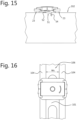
- the channel fastener 1 is thus rotated towards a second preliminary mounting state, which is shown in Figs. 13 - 16 .
- the spring members 51 will engage the flanges 104 of the channel element 100 and rub over the upper side of the flanges 104. Thereby the spring members 51, in particular the tongues 52, will be flexed towards the washer element 2 which results in a spring force.
- the respective flanges 104 enter a space between the washer element 2 and the longitudinal end portions of the oblong anchoring element 3. These spaces will be called herein an accommodation space indicated by reference numeral 61.
- the channel fastener 1 thus has two accommodation spaces 61 for accommodating the two flanges 104 of the channel element 100.
- the spring elements 51 push the washer element 2 away from the upper side of the flanges 104 and pull the anchoring element 3 towards the underside of the flanges, in this case with the edge 105 of the flanges 104.
- the main body 43 will not be clamped anymore between the flanges 104, because it has a smaller longitudinal dimension than the width w s of the slot 106 as mentioned in the above.
- the user can slide the fastener 1 along the channel element 100.
- the flanges 104 of the channel element 100 are located in the accommodation spaces 61 and the upper edge 50 of the upstanding wall portions 49A engage the edge 105 of the flanges 104.
- the elastic nature of the plastic material of the support 4 allows that the respective wall portions 49A can slide over the edge 105 of the respective flanges 104. In particular this also works when the edge is serrated, i.e. provided with teeth, as is indicated in Fig. 13 by reference numeral 105A.
- the upper edge 50 of the wall portion 49A in rest resides between two teeth of the serration, but the wall portion can deform to pass the teeth of the serration during movement of the fastener 1 along the channel element 100.
- the wall portions 49A are sturdy enough to maintain the fastener 1 in position on the channel element 100, when it is not pushed along the channel element 100 by a user.
- the sturdiness is improved by the transverse wall portion 49B integrally formed with the longitudinal wall portion 49A, which provides rigidity to the corner piece 49.
- An advantage of the wall portions 49A engaging the edges 105 of the flanges 104 is that it does not depend on the thickness of the anchoring element 3 how easy the fastener can be slid along the channel element.
- the thickness of anchoring elements may vary considerably due to tolerances in blank material and due to manufacturing tolerances.
- the dimensional relation between the wall portion 39A and the spring members 51 is better defined than the relation between the thickness of the anchoring element 3 and the spring elements 51. Therefore, and also due the flexible nature of the wall portion 39A the fastener 1 can provide a fairly constant and predefined holding force by the support 4 itself and thus a predefined and constant force to overcome the friction to move the fastener 1 along the channel element 100.
- the support 4 furthermore includes one or more resilient retention fingers 53 having a proximal end 53A connected to the head portion 40 and a distal end 53B located near or in contact with the anchoring element 3, as can be best seen in Figs. 2 , 4 , 5 and 8 .
- the retention fingers 53 extend from the main body obliquely towards the upper side of the anchoring element 3 and are adapted to retain the anchoring element 3 on the bottom plate 48 of the support 4 in an unmounted state.
- the retention fingers 53 however allow that the anchoring element 3 is moved towards the washer element 2 when the washer element 2 and the anchoring element 3 are tightened together by a male fastening element, possibly in cooperation with a nut. Thereto the retention fingers 53 are resiliently deformable.
- the oblique position of the retention fingers 53 facilitates their deformation for allowing the anchoring element 3 to move towards the washer element 2.
- the retention fingers 53 allow the support 4 to be used flexibly with anchoring elements 3 with different thicknesses. It is noted that retention fingers can be omitted in theory, and that for example on an inner side of the connecting legs 52, a retention lug may be formed which extends over the upper edge of the anchoring element 3 as is known from the prior art (e.g. from USD 494,887). Such a retention lug however is not as convenient in use when it comes to varying thicknesses of the anchoring element 3.
- a male fastener can inserted through the passages 6 and 56 and screwed into the bore 5 in the anchoring element 3.
- a nut on the male fastening element can be used to tighten the channel fastener 100 on the channel element 100.
- a blocking finger 54 is formed on an end of at least one of the spring members 51.
- the blocking finger 54 extends downwards under an angle with respect to the tongue 52.
- the tongue 52 rests on the upper side of the flange of the channel element 100 and the blocking finger 54 extends beyond the edge of at least one of the flanges 104 and a side wall 103 of the channel element 100, so as to block unintentional rotation of the fastener from that preliminary mounting state.
- This may for example be useful when the channel fastener 1 is released from a fixed state, in which the washer element 2 and the anchoring element 3 are clamped against the flanges 104, to a preliminary mounting state shown in Figs.
- the cooperating male fastening element e.g. a threaded rod and a cooperating nut are released and thus the nut is rotated counter-clockwise.
- the blocking fingers 54 prevent that the entire channel fastener 1 starts to rotate due to frictional forces.
Description
- The invention relates to a channel fastener for fastening an object to an elongate channel element, wherein said channel element has a bottom, an upper side opposite the bottom and lateral walls that interconnect the upper side and the bottom, wherein the upper side includes flanges that extend from the lateral walls towards each other and a longitudinal slot defined between the flanges and having a slot width,
- wherein the fastener comprises an assembly of:
- a rigid washer element, preferably made of metal, having a bearing face that is arranged for resting against the outer side of the flanges of the channel element,
- an oblong metal anchoring element having a width smaller than the slot width and a larger length larger than the slot width, said anchoring element being located on the side of the washer element where the bearing face is located and has longitudinal end portions adapted to engage an inner side of the respective flanges of the channel element,
- a support for the anchoring element, which support is connected to the washer element, possibly detachably, and which support carries the anchoring element,
- the fastener having between the washer element and each longitudinal end portion of the anchoring element an accommodation space which is accessible from the side of the fastener, each accommodation space being adapted for the accommodation of a flange of the channel element, in such a way that the fastener with its oblong anchoring element can be aligned with the longitudinal slot and the anchoring element can be inserted through the longitudinal slot into the channel element, and in such a way that subsequently after turning of the fastener, preferably a quarter turn, the anchoring element extends at an angle, preferably substantially at right angles, relative to the longitudinal slot, so that the flanges of the channel element are located in the accommodation spaces, wherein the anchoring element and the washer element can subsequently be tensioned towards each other wherein the longitudinal end portions of the anchoring element engage the inner side of the flanges of the channel element in order to fix the fastener to the channel element,
- wherein the support comprises:
- a head portion having one or more coupling members, which coupling members, possibly detachably, couple the washer element to the support,
- a bottom portion which supports the anchoring element from below, and
- connecting legs, each extending from the head portion to the bottom portion below the anchoring element, and connecting the head portion and the bottom portion, wherein the connecting legs extend along a longitudinal side of the oblong anchoring element.
- Such a channel fastener is typically used with channel elements, in the technical field concerned often called mounting rails. A particular type of mounting rail that the channel fasteners are used with is known in the field as a "strut rail", which is a mounting rail having generally a C-shaped cross section, wherein the flanges are folded inwardly such that the edges of the flanges are facing the bottom of the rail. However, the channel fasteners can also be used with normal C-shaped rails, having flanges that extend with their edges towards each other, or other channel type profiles that have flanges defining a slot between them.
- The
US Design Patent 494,887 shows a channel fastener for use with mounting rails. This known channel fastener is an assembly of a metal washer element, a plastic support and a metal anchoring element. The metal anchoring element is formed as an oblong nut with a threaded bore in the centre. On an upper side of the oblong nut grooves are formed which extend in the transverse direction. This is typical for channel fasteners which are used in combination with strut rails. The edges of the respective flanges of the strut rail are in a mounted state received in the respective grooves on the upper side of the nut. The plastic support is an integrally formed part including a cage which carries the metal anchoring element, and furthermore including a head portion that is connected to the washer. Two opposite spring elements surrounding the washer element are connected to the head portion and are adapted to engage flanges of the channel element. The oblong anchoring element of the fastener can be aligned with the longitudinal slot of a channel element and subsequently the anchoring element can be inserted through the longitudinal slot into the channel element. Subsequently after turning of the fastener, the anchoring element extends at an angle relative to the longitudinal slot, such that the flanges of the channel element are located in accommodation spaces between the washer element and longitudinal end portions of the anchoring element. In this position the spring elements engage the flanges of the channel element and pull the fastener upwards such that the longitudinal end portions of the anchoring element are pulled in engagement with the flanges of the channel element. In this state the channel fastener is in a preliminary mounting state, in which it is held stationary on the channel element by the spring force of the spring elements and can still be readily moved along the channel element towards its desired position. When the fastener is in its desired position, the anchoring element and the washer element can be tensioned towards each other by means of a male fastening element such as a threaded rod screwed in the oblong anchoring element and a nut engaging the washer element. The flanges of the channel element are thereby clamped between the longitudinal end portions of the anchoring element and the washer element in order to fix the fastener to the channel element. - It is an object of the present invention to provide a channel fastener which allows an easier first positioning and retaining into the desired position on the channel element.
- This object can be achieved by a channel fastener for fastening an object to an elongate channel element, wherein said channel element has a bottom, an upper side opposite the bottom and lateral walls that interconnect the upper side and the bottom, wherein the upper side includes flanges that extend from the lateral walls towards each other and a longitudinal slot defined between the flanges and having a slot width,
- wherein the fastener comprises an assembly of:
- a rigid washer element, preferably made of metal, having a bearing face that is arranged for resting against the outer side of the flanges of the channel element,
- an oblong metal anchoring element having a width smaller than the slot width and a larger length larger than the slot width, said anchoring element being located on the side of the washer element where the bearing face is located and has longitudinal end portions adapted to engage an inner side of the respective flanges of the channel element,
- a support for the anchoring element, which support is connected to the washer element, possibly detachably, and which support carries the anchoring element,
- the fastener having between the washer element and each longitudinal end portion of the anchoring element an accommodation space which is accessible from the side of the fastener, each accommodation space being adapted for the accommodation of a flange of the channel element, in such a way that the fastener with its oblong anchoring element can be aligned with the longitudinal slot and the anchoring element can be inserted through the longitudinal slot into the channel element, and in such a way that subsequently after turning of the fastener, preferably a quarter turn, the anchoring element extends at an angle, preferably substantially at right angles, relative to the longitudinal slot, so that the flanges of the channel element are located in the accommodation spaces, wherein the anchoring element and the washer element can subsequently be tensioned towards each other wherein the longitudinal end portions of the anchoring element engage the inner side of the flanges of the channel element in order to fix the fastener to the channel element,
- wherein the support comprises:
- a head portion having one or more coupling members, which coupling members, possibly detachably, couple the washer element to the support,
- a bottom portion which supports the anchoring element from below, and
- connecting legs, each extending from the head portion to the bottom portion below the anchoring element, and connecting the head portion and the bottom portion, wherein the connecting legs extend along a longitudinal side of the oblong anchoring element,
- wherein the support is made of an elastic material and in that the head portion and the connecting legs of the support form a tapering width from the head portion towards the bottom portion of the support, wherein at least the head portion at the location where it adjoins the legs has an initial width that exceeds the width of the longitudinal slot, such that when the anchoring element is aligned with the longitudinal slot of the channel element and inserted through the slot in the channel element, the legs and/or the head portion rub against the flanges and are/is elastically compressed such that the fastener can be held clamped between the flanges in a first preliminary mounting state.
- The support of the channel fastener according to the invention is made of an elastic material, preferably a thermoplastic material. The head portion and the connecting legs of the support form a tapering width from the head portion towards the bottom portion of the support. At least the head portion at the location where it adjoins the legs has an initial width that exceeds the width of the longitudinal slot of the channel element, such that when the anchoring element is aligned with the longitudinal slot of the channel element and inserted through the slot in the channel element, the legs and/or the head portion rub against the flanges and are/is elastically compressed such that the fastener can be held clamped between the flanges in a first preliminary mounting state. The user can position the fasteners according to the invention roughly on the channel element using the first preliminary mounting state before turning the fastener to a second preliminary mounting state. Both in the first and second preliminary mounting state the fastener can be shifted along the channel element.
- In a preferred embodiment of the channel fastener according to the invention, the support is made of a thermoplastic material. In practice the thermoplastic support will be made by an injection moulding process.
- In a possible embodiment of the channel fastener according to the invention, the head portion of the support comprises a main body having a central passage from the washer element towards the anchoring element, wherein two longitudinal slits extend from the central passage in the main body, said longitudinal slits being opened wide in an unloaded state and being closed in the first preliminary mounting state. The central opening allows a male fastener, such as a threaded rod, to be passed through the main body to extend from the anchoring element to the washer element. In a non-loaded state the slits are spread open. When the anchoring element is aligned with the slot of the channel element, the slits extend substantially parallel with the slot of the channel element. When the channel fastener is inserted in the slot, the slits are closed by the compression force provided by the flanges in cooperation with the tapering width form of the head and the legs of the support. When the main body is turned to a second preliminary mounting state, it will not rub against the flanges anymore and the slits will open again by the elasticity of the main body.
- In a possible embodiment of the channel fastener according to the invention, the support includes one or more spring members associated with the head portion of the support, wherein said spring members force the bottom portion and the anchoring element towards the inner side of the flanges of the channel element in a second preliminary mounting state in which the flanges are located in the accommodation spaces. The spring elements provide a holding force to keep the channel fastener in position on the channel element, in the second preliminary mounting state. In a possible embodiment the spring members extend from the head portion of the support element into the accommodation space, such that when the fastener is rotated in the channel element towards the second preliminary mounting state, the spring members will be deformed and tensioned by the flanges of the channel element.
- In another possible embodiment the spring members may be associated with the bottom portion of the support and resiliently support the anchoring element from below, such that when the fastener is rotated in the channel element towards the second preliminary mounting state, the spring members will be deformed and tensioned by the anchoring element which is forced towards the bottom portion by the flanges of the channel element. The anchoring element is thus resiliently held against the inner side of the flanges in the second preliminary mounting state.
- A problem of the known channel fastener of USD 494,887, is that the force with which the anchoring element is forced in engagement with the flanges in the preliminary mounting state depends on the thickness or height of the anchoring element, while in practise the thickness or height of the anchoring element can vary considerably, for example due to manufacturing tolerances. The force also determines how well the fastener is maintained in position on the channel element, but also determines how easy the fastener can be moved towards the desired position along the channel element in the preliminary mounting state, in which the flanges of the channel element are located in the accommodation spaces of the fastener. This problem comes forward even more when the fastener is used with a strut rail and the anchoring element has grooves. Often the downwardly pointing edges of the flanges of the strut rail are provided with notches or are serrated. Also the grooves in the anchoring element may have notches which engage with the notches or serrations of the flange edges.
- In a possible embodiment of the channel fastener according to the invention, the bottom portion comprises a bottom plate supporting the anchoring element and upstanding wall members extending upwardly from the bottom plate, wherein the upstanding wall members includes at least a longitudinal wall portion that extends at the longitudinal end portions of the anchoring element along a side of the anchoring element having the largest length, and wherein the upstanding wall portions have a height that exceeds the thickness of the anchoring element, such that when the anchoring element is in engagement with the bottom plate, an upper edge of the upstanding wall is located above the anchoring element and such that when the fastener is in the position wherein the flanges of the channel element are located in the accommodation spaces, the upper edge of the upstanding wall portions engage the inner side of the flanges in said second preliminary mounting state.
- An advantage of the one or more upstanding wall portions engaging the inner side of the flanges is that it does not depend on the thickness of the anchoring element how easy the fastener can be slid along the channel element. The dimensional relation between the upstanding wall portion and the spring members can be well defined in the design of the support. Therefore, and also due the flexible nature of the upstanding wall portion the channel fastener can provide a fairly constant and predefined holding force by the support itself, independent of the anchoring element the support is assembled with. The force needed to overcome the friction to move the fastener along the channel element is thus also constant and predetermined.
- The upstanding wall members may be located at two diagonally opposite corners of the oblong anchoring element. In this way each flange of the channel element engages only one upstanding wall portion. Thereby the resistance against movement of the channel fastener along the channel element can be well defined.
- In a further embodiment the wall members furthermore comprise a transversal wall portion extending at an angle, preferably perpendicular, to the longitudinal wall portion, and forming a corner piece with the corresponding longitudinal wall portion. The transversal wall portion provides rigidity to the wall member, and also provides a locking means to retain the anchoring element on the bottom portion of the support in the longitudinal direction.
- In a possible embodiment the spring members are formed as tongues which extend obliquely from the head portion towards the anchoring element.
- A problem that may occur with the known channel fastener of USD 494,887 is that when it is mounted on a channel element and secured by a male fastening element, e.g. a threaded rod, and a cooperating nut, it may in some occasions be necessary to release the nut so as to be able to move the channel fastener along the channel element or rail. However, releasing the nut means that a rotational force is applied on the assembly of the channel fastener and the male fastening element, which may cause the channel fastener to be rotated out of the preliminary mounting state in which the flanges are located in the accommodation spaces. Thereby the fastener may be unintentionally loosened and displaced or even removed from the channel element.
- In a possible embodiment a blocking finger is formed on an end of at least one of the spring members, wherein said blocking finger extends in the second preliminary mounting state beyond the edge of at least one of the flanges and a side wall of the channel element, so as to block unintentional rotation of the fastener from the second preliminary mounting state.
- The blocking finger prevents that the entire channel fastener starts to rotate due to rotational forces applied to the fastener, e.g. when a nut is loosened on a threaded rod which is connected with the channel fastener. If the installing person wants to remove the channel fastener altogether, the flexibility of the spring members allows that the installer forces the blocking fingers over the edge of the flanges and lateral wall of the channel element again by lifting the spring members. However, if the spring members are not "helped" they are sturdy enough to keep the channel fastener in the preliminary mounting state on the channel element.
- This may for example be useful when the channel fastener is released from a fixed state, in which the washer element and the anchoring element are clamped by a threaded rod/nut connection against the flanges of the channel element to a preliminary mounting state in which the channel fastener can be shifted along the channel element.
- In a possible embodiment the support includes one or more resilient retention fingers having a proximal end connected to the head portion and a distal end located near or in contact with the anchoring element, so as to retain the anchoring element on the bottom portion of the support. The retention fingers allow that anchoring elements having varying thicknesses can be assembled with the same support whilst the anchoring element is securely retained on the bottom portion by the retention fingers. The retention fingers are adapted to allow that the anchoring element is moved towards the washer element when the washer element and the anchoring element are tightened together by a male fastening element, possibly in cooperation with a nut. Thereto the retention fingers are resiliently deformable.
- Preferably the retention fingers extend from the main body obliquely towards the upper side of the anchoring element and are adapted to retain the anchoring element on a bottom plate of the support in an unmounted state. The oblique position of the retention fingers facilitates their deformation for allowing the anchoring element to move towards the washer element.
- In a possible embodiment of the channel fastener, the one or more retention fingers extend from the head portion downward and in transverse direction of the nut. This arrangement of the retention fingers prevents that the retention fingers interfere with the rotation of the fastener on the channel element to a preliminary mounting state in which the flanges of the channel element are received in the accommodation spaces of the channel fastener.
- In a possible embodiment of the channel fastener, the retention fingers are arranged in pairs, wherein, preferably the retention fingers of one pair together generally form a V-shape.
- In a possible further embodiment of the channel fastener, the support includes two pairs of retention fingers, one on each side of the body adjacent the accommodation spaces of the channel fastener.
- In a possible embodiment of the channel fastener, the bottom portion comprises a bottom plate supporting the anchoring element and the retention fingers push the anchoring element against the bottom plate.
- The invention also relates to a combination of a fastener according to any aspect of the invention as described in the above and a channel element having a bottom, an upper side opposite the bottom and lateral walls that interconnect the upper side and the bottom, wherein the upper side includes flanges that extend from the lateral walls towards each other and a longitudinal slot defined between the flanges and having a slot width, wherein the channel element is of the so called "strut rail" type, i.e. the channel element has inwardly folded flanges, wherein the flanges have edges that are facing the bottom of the channel element.
- In a possible embodiment the edge of the respective flanges are serrated.
- The invention also relates to a method for assembling a fastener according to any aspect of the invention as described in the above to a channel element, wherein the channel fastener is mounted in a first preliminary state and a second preliminary state on the channel element before it is finally secured to the channel element.
- The invention will be further elucidated in the following description with reference to the drawing, wherein:
-
Fig. 1 shows in a first view in perspective a possible embodiment of the channel fastener according to the invention, -
Fig. 2 shows in a second view in perspective the channel fastener ofFig. 1 , -
Fig. 3 shows in a third view in perspective the channel fastener ofFig. 1 , -
Fig. 4 shows a side elevational view from a transverse side of the channel fastener ofFig. 1 , -
Fig. 5 shows a side elevational view from a longitudinal side of the channel fastener ofFig. 1 , -
Fig. 6 shows a top elevational view of the channel fastener ofFig. 1 , -
Fig. 7 shows in a first view in perspective a support of the channel fastener ofFig. 1 , -
Fig. 8 shows in a second view in perspective the support of the channel fastener ofFig. 1 , -
Fig. 9 shows a side elevational view of the fastener ofFig. 1 during insertion in the slot of a channel element, -
Fig. 10 shows a side elevational view of the fastener ofFig. 1 in a first preliminary mounting state, -
Fig. 11 shows a top elevational view of the support ofFig. 7 in an unloaded state, -
Fig. 12 shows a top elevational view of the support ofFig. 7 in the first preliminary mounting state ofFig. 10 , -
Fig. 13 shows in a view in perspective an assembly of the channel fastener ofFig. 1 arranged in a second preliminary mounting state on a channel element, -
Fig. 14 shows a side elevational view of the assembly ofFig. 13 , -
Fig. 15 show another side elevational view of the assembly ofFig. 13 , and -
Fig. 16 shows a top elevational view of the assembly ofFig. 13 . - The present invention relates to a channel fastener adapted to be mounted on a channel element. Such a channel element is in practice also called a mounting rail.
- In
Fig. 9 ,Fig. 13 andFig. 16 such a channel element or mounting rail is visible in cross section, perspective view and top elevation view, respectively. The mounting rail indicated byreference numeral 100 in general has a bottom 101, anupper side 102 opposite the bottom 101 andlateral walls 103 that interconnect theupper side 102 and the bottom 101. Theupper side 102 of the channel element includesflanges 104 that extend from thelateral walls 103 towards each other and includes alongitudinal slot 106 defined between theflanges 104. Thelongitudinal slot 106 has a slot width ws. Thechannel element 100 shown here is specifically called a "strut rail" in the technical field concerned. Such a strut rail has the characteristic that theflanges 104 are folded inwardly such that theedges 105 of theflanges 104 are pointing towards thebottom 101 of thechannel element 100. It is noted that the invention will be explained in combination with a strut rail, which is a preferred channel element, but that a channel fastener according to the invention may also be used in combination with other channel elements, e.g. having a regular C-shaped cross section. - In
Figs. 1 - 3 a possible embodiment of a channel fastener according to the invention is shown and indicated byreference numeral 1. - The
channel fastener 1 is an assembled part which generally comprises awasher element 2, ananchoring element 3, and asupport 4. Thewasher element 2 is preferably made of metal, but may in some occasions also be made of a suitable plastic material, such as POM. The anchoringelement 3 is made of metal. Thesupport 4 is made of an elastic material which interconnects thewasher element 2 and theanchoring element 3. - A suitable material for manufacturing the
support element 4 is a thermoplastic material. Thesupport 4 is in practice made from the thermoplastic material by an injection moulding process. - The
metal washer 2 and themetal anchoring element 3 are made by suitable cutting, punching and forming processes, preferably out of steel strip or sheet material. - The anchoring
element 3 may be formed as an elongate nut having a central threadedbore 5, adapted to cooperate with a shaft of a male fastening element such as a threaded rod or a bolt. The anchoringelement 3 has a width wa that is smaller than the width ws of theslot 106 of thechannel element 100. The anchoring element has a length la which exceeds the width ws of theslot 106. On anupper side 31 of theanchoring element 3grooves 32 are formed which extend in the transverse direction. Thesegrooves 32 are typical for channel fasteners adapted for use on strut rails, wherein theedges 105 of theflanges 104 can be received in thegrooves 32, at least in a final mounting state. - The
washer element 2 has acentral bore 6 for passing through the shaft of the male fastening element. In the shown embodiment thewasher element 2 substantially has a rectangular or square outer contour. The washer element in this specific embodiment comprises acentral strip 21, i.e. the strip in which thebore 6 is formed, and twolateral strips 22 which are offset relative to thecentral strip 21 in a thickness direction of thewasher element 2, which can be seen also inFigs. 4 - 6 . The lateral strips 22 are adapted to rest with a bearingface 23 on theflanges 104 of thechannel element 1 in final mounting state in which thewasher element 2 and theanchoring element 3 are tightened towards each other by a male fastening element and a nut cooperating with the male fastening element wherein the nut engages thewasher element 3 from above. - The
support 4, which is shown separately inFigs. 7 and 8 , comprises ahead portion 40 and abottom portion 41. Thehead portion 40 and thebottom portion 41 are interconnected by connectinglegs 42. - In the specific embodiment shown in the figures, the
head portion 40 comprises amain body 43, and awasher support plate 44 which is integrally formed with themain body 43. At the respective ends of thewasher support plate 44coupling members 45 are formed to couple thewasher element 2 to thehead portion 40 of thesupport 4. Thecoupling members 45 comprise each astop ridge 46 which forms a stop for the head ends of thecentral strip 21 of thewasher element 2. Thecoupling members 45 furthermore compriseretention fingers 47 at the ends of thestop ridge 46 which in the assembled state extend over the lateral strips 22 of thewasher element 2 as can be best seen inFigs 3 ,5 and7 . Since thecentral strip 21 of thewasher element 2 lies in height offset with respect to the lateral strips 21, theretention fingers 47 lock thewasher element 2 in the height direction and in the lateral direction. Thestop ridge 46 locks thewasher 2 in the longitudinal direction. - The
main body 43 and thewasher support plate 44 define acentral passage 56 through which a male fastener, such as a threaded rod, can extend. Twolongitudinal slits 57 extend from thecentral passage 56 in themain body 43 and in thewasher supporting plate 44 each towards a respective longitudinal end of thewasher support plate 44 where thecoupling members 45 are formed. Thelongitudinal slits 57 are opened wide in an unloaded state as is visible inFigs. 7, 8 and11 . Thelongitudinal slits 57 are closed in a first preliminary mounting state which will be described further below, and as is visible inFig. 12 - The
bottom portion 41 is adapted to support the anchoringelement 3 from below. Thebottom portion 41 comprises in the specific embodiment shown in the figures abottom plate 48, which supports the anchoringelement 3 from below. Thebottom portion 41 furthermore comprisesupstanding wall members 49 extending upwardly from thebottom plate 48. - The
upstanding wall members 49 comprise at least alongitudinal wall portion 49A that extends at the longitudinal end portions of theanchoring element 3 along the side of theanchoring element 3 having the largest length. Theupstanding wall members 49 furthermore comprise atransversal wall portion 49B extending at an angle, in the specific embodiment of the figures perpendicular, to thelongitudinal wall portion 49A, and forming a corner piece with the correspondinglongitudinal wall portion 49A. The specific embodiment of thesupport 4 shown in the figures has at two diagonally opposite corners of the support plate 48 a corner piece orwall member 49 to lock theanchoring element 3 in the transversal and longitudinal direction. - At least the
upstanding wall portions 49A have a height that exceeds the thickness of theanchoring element 3, as can be best seen inFigs. 2 ,4 and 5 . In the embodiment shown in the figures thewall portions 49B also have a height that exceeds the thickness of theanchoring element 3, however these allportions 49B may also be lower or even with a slanting upper edge. When the anchoringelement 3 is in engagement with thebottom plate 48, anupper edge 50 of at least theupstanding wall portion 49A is located above the anchoringelement 3. - The connecting
legs 42 are each extending from themain body 43 of thehead portion 40 to thebottom plate 48 of thebottom portion 41. The connectinglegs 42 extend along a longitudinal side of theoblong anchoring element 3, as can be best seen inFigs. 3 - 5 . - The
main body 43 of thesupport 4 and the connectinglegs 42 together have a tapering shape as can be best seen inFigs. 4 and9 . Themain body 43 has a greater width wmax at an upper side and the width of the main body and thelegs 42, lying in line with the outer contour of themain body 43, decrease towards thebottom portion 41. At the lower end of the legs the width wmin is smaller than the width ws of theslot 106 of thechannel element 100. The greater width wmax exceeds in an unloaded state the width ws of theslot 106 of thechannel element 100. It is noted that themain body 43 of thesupport 4 has a smaller dimension in a direction perpendicular to wmax, which dimension is preferably smaller than the width ws of theslot 106, such that when thechannel fastener 1 is turned a quarter turn in thechannel element 100, themain body 43 will not engage theflanges 104 anymore as will be described further below. - During installation, the user inserts the
bottom portion 41 of thesupport 4 with the anchoringelement 3 in theslot 106 of thechannel element 100. This situation is shown inFig. 9 . Thebottom portion 41 and the lower end of the connectinglegs 42 fit between theflanges 104. When thebottom portion 41 of thechannel fastener 1 is moved further into thechannel element 100 the connectinglegs 42 and or themain body 43 will start to rub against theflanges 104 of thechannel element 100. This will cause a compression force on themain body 43 and possibly thelegs 42. This compression force will result in a deformation of themain body 43 wherein theslits 57 will be deformed from an open state as is shown inFig. 11 to a closed state which is shown inFig. 12 . InFig. 10 is shown the state in which themain body 43 of thesupport 4 is thus resiliently clamped between theflanges 104 of thechannel element 100. Thechannel fastener 1 can thus be held in this first preliminary mounting state on thechannel element 100. If necessary, the user can still shift thechannel fastener 1 longitudinally along thechannel element 100 to move it to the desired position on thechannel element 100. - The
support 4 furthermore includesspring members 51. In the specific embodiment shown in the figures, thespring members 51 are associated with thehead portion 40 of thesupport 4 at a longitudinal end portion of thewasher support plate 44. Thespring members 51 in this specific embodiment comprisetongues 52 which extend obliquely from an underside of thewasher support plate 44 of thehead portion 40 of thesupport 4 towards the anchoringelement 3. - When the
channel fastener 1 is in the first preliminary mounting state, as shown inFig. 10 , it can be rotated as is indicated by arrow 60 (cf.Figs. 1 - 3 ). In this example thearrow 60 is provided on the top surface of the washer, but such an arrow may be omitted. Thechannel fastener 1 is thus rotated towards a second preliminary mounting state, which is shown inFigs. 13 - 16 . During the rotation thespring members 51 will engage theflanges 104 of thechannel element 100 and rub over the upper side of theflanges 104. Thereby thespring members 51, in particular thetongues 52, will be flexed towards thewasher element 2 which results in a spring force. When thefastener 1 is turned, preferably a quarter turn, as is shown inFigs. 13 - 16 , therespective flanges 104 enter a space between thewasher element 2 and the longitudinal end portions of theoblong anchoring element 3. These spaces will be called herein an accommodation space indicated byreference numeral 61. Thechannel fastener 1 thus has twoaccommodation spaces 61 for accommodating the twoflanges 104 of thechannel element 100. When theflanges 104 are in theaccommodation spaces 61, thespring elements 51 push thewasher element 2 away from the upper side of theflanges 104 and pull theanchoring element 3 towards the underside of the flanges, in this case with theedge 105 of theflanges 104. Since theupper edge 50 of the respectivelongitudinal wall portions 49A extends above the upper side of theanchoring element 3, theupper edge 50 of thelongitudinal wall portions 49A will be pulled in engagement with theedge 105 of therespective flanges 104, which is best visible inFig. 14 . - In the second preliminary mounting state the
main body 43 will not be clamped anymore between theflanges 104, because it has a smaller longitudinal dimension than the width ws of theslot 106 as mentioned in the above. The user can slide thefastener 1 along thechannel element 100. Theflanges 104 of thechannel element 100 are located in theaccommodation spaces 61 and theupper edge 50 of theupstanding wall portions 49A engage theedge 105 of theflanges 104. The elastic nature of the plastic material of thesupport 4 allows that therespective wall portions 49A can slide over theedge 105 of therespective flanges 104. In particular this also works when the edge is serrated, i.e. provided with teeth, as is indicated inFig. 13 byreference numeral 105A. Theupper edge 50 of thewall portion 49A in rest resides between two teeth of the serration, but the wall portion can deform to pass the teeth of the serration during movement of thefastener 1 along thechannel element 100. However, thewall portions 49A are sturdy enough to maintain thefastener 1 in position on thechannel element 100, when it is not pushed along thechannel element 100 by a user. The sturdiness is improved by thetransverse wall portion 49B integrally formed with thelongitudinal wall portion 49A, which provides rigidity to thecorner piece 49. An advantage of thewall portions 49A engaging theedges 105 of theflanges 104 is that it does not depend on the thickness of theanchoring element 3 how easy the fastener can be slid along the channel element. It is noted that the thickness of anchoring elements may vary considerably due to tolerances in blank material and due to manufacturing tolerances. The dimensional relation between the wall portion 39A and thespring members 51 is better defined than the relation between the thickness of theanchoring element 3 and thespring elements 51. Therefore, and also due the flexible nature of the wall portion 39A thefastener 1 can provide a fairly constant and predefined holding force by thesupport 4 itself and thus a predefined and constant force to overcome the friction to move thefastener 1 along thechannel element 100. - In the specific embodiment of the figures the
support 4 furthermore includes one or moreresilient retention fingers 53 having aproximal end 53A connected to thehead portion 40 and adistal end 53B located near or in contact with the anchoringelement 3, as can be best seen inFigs. 2 ,4 ,5 and8 . Theretention fingers 53 extend from the main body obliquely towards the upper side of theanchoring element 3 and are adapted to retain theanchoring element 3 on thebottom plate 48 of thesupport 4 in an unmounted state. Theretention fingers 53 however allow that the anchoringelement 3 is moved towards thewasher element 2 when thewasher element 2 and theanchoring element 3 are tightened together by a male fastening element, possibly in cooperation with a nut. Thereto theretention fingers 53 are resiliently deformable. The oblique position of theretention fingers 53 facilitates their deformation for allowing the anchoringelement 3 to move towards thewasher element 2. Theretention fingers 53 allow thesupport 4 to be used flexibly with anchoringelements 3 with different thicknesses. It is noted that retention fingers can be omitted in theory, and that for example on an inner side of the connectinglegs 52, a retention lug may be formed which extends over the upper edge of theanchoring element 3 as is known from the prior art (e.g. from USD 494,887). Such a retention lug however is not as convenient in use when it comes to varying thicknesses of theanchoring element 3. - In the preliminary mounting position shown in
Figs. 13 - 16 a male fastener can inserted through thepassages bore 5 in theanchoring element 3. A nut on the male fastening element can be used to tighten thechannel fastener 100 on thechannel element 100. - A blocking
finger 54 is formed on an end of at least one of thespring members 51. The blockingfinger 54 extends downwards under an angle with respect to thetongue 52. In the second preliminary mounting state as is shown inFigs. 13 - 16 , thetongue 52 rests on the upper side of the flange of thechannel element 100 and the blockingfinger 54 extends beyond the edge of at least one of theflanges 104 and aside wall 103 of thechannel element 100, so as to block unintentional rotation of the fastener from that preliminary mounting state. This may for example be useful when thechannel fastener 1 is released from a fixed state, in which thewasher element 2 and theanchoring element 3 are clamped against theflanges 104, to a preliminary mounting state shown inFigs. 13 - 16 . For releasing thefastener 1, the cooperating male fastening element, e.g. a threaded rod and a cooperating nut are released and thus the nut is rotated counter-clockwise. The blockingfingers 54 prevent that theentire channel fastener 1 starts to rotate due to frictional forces.
Claims (14)
- Channel fastener (1) for fastening an object to an elongate channel element (100), wherein said channel element has a bottom (101), an upper side (102) opposite the bottom and lateral walls (103) that interconnect the upper side and the bottom, wherein the upper side (102) includes flanges (104) that extend from the lateral walls (103) towards each other and a longitudinal slot (106) defined between the flanges (104) and having a slot width (ws),wherein the fastener (1) comprises an assembly of:- a rigid washer element (2), preferably made of metal, having a bearing face (23) that is arranged for resting against the outer side of the flanges (104) of the channel element (100),- an oblong metal anchoring element (3) having a width (wa) smaller than the slot width (ws) and a length (la) larger than the slot width (ws), said anchoring element (3) being located on the side of the washer element (2) where the bearing face (23) is located and has longitudinal end portions adapted to engage an inner side of the respective flanges (104) of the channel element (100),- a support (4) for the anchoring element (3), which support (4) is connected to the washer element (2), possibly detachably, and which support (4) carries the anchoring element (3),the fastener (1) having between the washer element (2) and each longitudinal end portion of the anchoring element (3) an accommodation space (61) which is accessible from the side of the fastener (1), each accommodation space (61) being adapted for the accommodation of a flange (104) of the channel element (100), in such a way that the fastener (1) with its oblong anchoring element (3) can be aligned with the longitudinal slot (106) and the anchoring element (3) can be inserted through the longitudinal slot (106) into the channel element (100), and in such a way that subsequently after turning of the fastener (1), preferably a quarter turn, the anchoring element (3) extends at an angle, preferably substantially at right angles, relative to the longitudinal slot (106), so that the flanges (104) of the channel element (100) are located in the accommodation spaces (61), wherein the anchoring element (3) and the washer element (2) can subsequently be tensioned towards each other wherein the longitudinal end portions of the anchoring element (3) engage the inner side of the flanges (104) of the channel element (100) in order to fix the fastener (1) to the channel element (100),wherein the support (4) comprises:- a head portion (40) having one or more coupling members (45), which coupling members, possibly detachably, couple the washer element (2) to the support (4),- a bottom portion (41) which supports the anchoring element (3) from below, and- connecting legs (42), each extending from the head portion (40) to the bottom portion (41) below the anchoring element (3), and connecting the head portion (40) and the bottom portion (41), wherein the connecting legs (42) extend along a longitudinal side of the oblong anchoring element (3),characterized in that the support (4) is made of an elastic material and in that the head portion (40) and the connecting legs (42) of the support (4) form a tapering width from the head portion (40) towards the bottom portion (41) of the support (4), wherein at least the head portion (40) at the location where it adjoins the legs (42) has an initial width that exceeds the width (ws) of the longitudinal slot (106), such that when the anchoring element (3) is aligned with the longitudinal slot (106) of the channel element (100) and inserted through the slot (106) in the channel element (100), the legs (42) and/or the head portion (40) rub against the flanges (104) and are/is elastically compressed such that the fastener (1) can be held clamped between the flanges (104) in a first preliminary mounting state.
- Fastener according to claim 1, wherein the support (4) is made of a thermoplastic material.
- Fastener according to claim 1 or 2, wherein the head portion (40) of the support (4) comprises a main body (43) having a central passage (56) from the washer element (2) towards the anchoring element (3), wherein two longitudinal slits (57) extend from the central passage (56) in the main body, said longitudinal slits (57) being opened wide in an unloaded state and being closed in the first preliminary mounting state.
- Fastener according to any of the preceding claims, wherein the support (4) includes one or more spring members (51) associated with the head portion (40) of the support (4), wherein said spring members (51) force the bottom portion (41) and the anchoring element (3) towards the inner side of the flanges (104) of the channel element (100) in a second preliminary mounting state in which the flanges (104) are located in the accommodation spaces (61).
- Fastener according to any of the claims 1-3, wherein the support (4) includes one or more spring members associated with the bottom portion (41) of the support (4), wherein said spring members force the anchoring element (3) towards the inner side of the flanges (104) of the channel element (100) in a second preliminary mounting state in which the flanges (104) are located in the accommodation spaces (61).
- Fastener according to claim 4, wherein the bottom portion (41) comprises a bottom plate (48) supporting the anchoring element (3) and upstanding wall members (49) extending upwardly from the bottom plate (48), wherein the upstanding wall members (49) includes at least a longitudinal wall portion (49A) that extends at the longitudinal end portions of the anchoring element (3) along a side of the anchoring element (3) having the largest length, and wherein the upstanding wall portions (49A) have a height that exceeds the thickness of the anchoring element (3), such that when the anchoring element (3) is in engagement with the bottom plate (48), an upper edge of the upstanding wall (49A) is located above the anchoring element (3) and such that when the fastener (1) is in the position wherein the flanges (104) of the channel element (100) are located in the accommodation spaces (61), the upper edge of the upstanding wall portions (49A) engage the inner side of the flanges (104) in said second preliminary mounting state.
- Fastener according to claim 6, wherein the upstanding wall members (49) are located at two diagonally opposite corners of the oblong anchoring element (3).
- Fastener according to claim 6 or 7, wherein the wall members (49) furthermore comprise a transversal wall portion (49B) extending at an angle, preferably perpendicular, to the longitudinal wall portion (49A), and forming a corner piece with the corresponding longitudinal wall portion (49A).
- Fastener according to any of the claims 4, 6 - 8, wherein the spring members (51) are formed as tongues (52) which extend obliquely from the head portion (40) towards the anchoring element (3).
- Fastener according to any of the claims 4, 6 - 9, wherein a blocking finger (54) is formed on an end of at least one of the spring members (51), wherein said blocking finger (54) extends in the second preliminary mounting state beyond the edge of at least one of the flanges (104) and a side wall (103) of the channel element (100), so as to block unintentional rotation of the fastener (1) from the second preliminary mounting state.
- Fastener according to any of the claims 1 - 10, wherein the support (4) includes one or more resilient retention fingers (53) having a proximal end connected to the head portion (40) and a distal end located near or in contact with the anchoring element (3), so as to retain the anchoring element (3) on the bottom portion (41) of the support (4).
- Combination of a fastener (1) according to any of the preceding claims and a channel element (100) having a bottom (101), an upper side (102) opposite the bottom and lateral walls (103) that interconnect the upper side and the bottom, wherein the upper side (102) includes flanges (104) that extend from the lateral walls (103) towards each other and a longitudinal slot (106) defined between the flanges (104) and having a slot width (ws), wherein the channel element (100) is of the so called "strut rail" type, i.e. the channel element (100) has inwardly folded flanges (104), wherein the flanges have edges (105) that are facing the bottom (101) of the channel element (100).
- Combination according to claim 12, wherein the edge (105) of the respective flanges (104) are serrated.
- Method for assembling a combination of any of the claims 12 - 13 to a channel element (100), wherein the channel fastener (1) is mounted in a first preliminary state and a second preliminary state on the channel element (100) before it is finally secured to the channel element (100).
Applications Claiming Priority (5)
| Application Number | Priority Date | Filing Date | Title |
|---|---|---|---|
| NL2021936A NL2021936B1 (en) | 2018-11-05 | 2018-11-05 | Channel fastener having anti-rotation blocking |
| NL2021937A NL2021937B1 (en) | 2018-11-05 | 2018-11-05 | Channel fastener having retention fingers |
| NL2021935A NL2021935B1 (en) | 2018-11-05 | 2018-11-05 | Channel fastener having flexible engagement of channel flange |
| NL2021934A NL2021934B1 (en) | 2018-11-05 | 2018-11-05 | Channel fastener having tapering support body |
| PCT/NL2019/050710 WO2020096447A1 (en) | 2018-11-05 | 2019-10-29 | Channel fastener having tapering support body |
Publications (3)
| Publication Number | Publication Date |
|---|---|
| EP3877663A1 EP3877663A1 (en) | 2021-09-15 |
| EP3877663B1 true EP3877663B1 (en) | 2023-08-16 |
| EP3877663C0 EP3877663C0 (en) | 2023-08-16 |
Family
ID=69061418
Family Applications (1)
| Application Number | Title | Priority Date | Filing Date |
|---|---|---|---|
| EP19829343.3A Active EP3877663B1 (en) | 2018-11-05 | 2019-10-29 | Channel fastener having tapering support body |
Country Status (6)
| Country | Link |
|---|---|
| US (1) | US11781585B2 (en) |
| EP (1) | EP3877663B1 (en) |
| CN (1) | CN112955670B (en) |
| ES (1) | ES2961060T3 (en) |
| PL (1) | PL3877663T3 (en) |
| WO (1) | WO2020096447A1 (en) |
Families Citing this family (2)
| Publication number | Priority date | Publication date | Assignee | Title |
|---|---|---|---|---|
| US11624395B2 (en) * | 2020-10-22 | 2023-04-11 | D Three Enterprises, Llc | Channel strut fasteners |
| AU2021106517B4 (en) * | 2021-06-18 | 2022-05-05 | Rhino Rack Australia Pty Limited | Fixing device for a channel |
Family Cites Families (17)
| Publication number | Priority date | Publication date | Assignee | Title |
|---|---|---|---|---|
| US494887A (en) | 1893-04-04 | Sawing-machine | ||
| US4285379A (en) | 1979-09-17 | 1981-08-25 | B-Line Systems, Inc. | Fastener |
| US4830531A (en) * | 1985-10-04 | 1989-05-16 | Unistrut International Corp. | Unitary connection assembly for metal channels and method for assembly |
| FR2754576B1 (en) * | 1996-10-16 | 1998-11-27 | Rapid Sa | NUT MOUNTING BY CLIPPAGE ON A PROFILE |
| DE29824254U1 (en) | 1998-05-12 | 2000-09-21 | Mefa Befestigungs Und Montages | Fastening device |
| DE19821255A1 (en) * | 1998-05-12 | 1999-11-18 | Kratzer F Mefa Duebel Gmbh | Mounting fixture for structure held within C-profiled extrusion |
| DE19903036C1 (en) * | 1999-01-26 | 2000-10-26 | Sw Stanzwerk Glarus Ag Glarus | Fastening element for anchoring in a mounting rail |
| GB2355776A (en) | 1999-10-29 | 2001-05-02 | Porchester Eng Co Ltd | Fixing assembly for channel sections |
| DE10052534A1 (en) * | 2000-10-23 | 2002-04-25 | Hilti Ag | Fastening element has stop against which acts preloaded spring element, and coupling section on stop and reciprocal coupling section on gripping element form connection |
| USD494887S1 (en) * | 2002-08-08 | 2004-08-24 | J. Van Walraven Bv | Channel fastener |
| NL1029499C2 (en) | 2005-07-12 | 2007-01-15 | Walraven Holding Bv J Van | Mounting assembly. |
| US7621487B2 (en) * | 2005-12-21 | 2009-11-24 | Securus, Inc. | Twist-lock base for pipe holders |
| DE102009000736A1 (en) * | 2009-02-10 | 2010-08-19 | Hilti Aktiengesellschaft | Fastening device for arranging a rod element on a mounting rail |
| WO2011056943A1 (en) | 2009-11-04 | 2011-05-12 | Illinois Tool Works Inc. | Removable and reusable quick nut |
| US8465242B2 (en) * | 2010-12-08 | 2013-06-18 | The United States Of America As Represented By The Secretary Of The Navy | Fastener for strut channel |
| DE102014214853A1 (en) * | 2014-07-29 | 2016-02-04 | Adolf Würth GmbH & Co. KG | Mounting arrangement for C-shaped retaining rails and kit |
| DE102017103769A1 (en) | 2017-02-23 | 2018-08-23 | Secura Services Ag | Fastening device and mounting assembly |
-
2019
- 2019-10-29 US US17/288,754 patent/US11781585B2/en active Active
- 2019-10-29 EP EP19829343.3A patent/EP3877663B1/en active Active
- 2019-10-29 WO PCT/NL2019/050710 patent/WO2020096447A1/en unknown
- 2019-10-29 CN CN201980072448.5A patent/CN112955670B/en active Active
- 2019-10-29 PL PL19829343.3T patent/PL3877663T3/en unknown
- 2019-10-29 ES ES19829343T patent/ES2961060T3/en active Active
Also Published As
| Publication number | Publication date |
|---|---|
| PL3877663T3 (en) | 2023-12-04 |
| CN112955670A (en) | 2021-06-11 |
| EP3877663A1 (en) | 2021-09-15 |
| US11781585B2 (en) | 2023-10-10 |
| EP3877663C0 (en) | 2023-08-16 |
| WO2020096447A1 (en) | 2020-05-14 |
| ES2961060T3 (en) | 2024-03-07 |
| CN112955670B (en) | 2023-02-24 |
| US20210396263A1 (en) | 2021-12-23 |
Similar Documents
| Publication | Publication Date | Title |
|---|---|---|
| US8016530B2 (en) | Panel fastener | |
| USRE36681E (en) | Channel nut fastener | |
| EP3877663B1 (en) | Channel fastener having tapering support body | |
| US7789606B2 (en) | Push-in nut | |
| US20080095591A1 (en) | Fastener assembly for metal framing | |
| US4263952A (en) | Fastener for metal framing | |
| EP3347957A1 (en) | Conduit clip | |
| EP0841493A2 (en) | Panel-fastener connector clip | |
| US11454032B2 (en) | Step clip fastening system and method | |
| US20230399854A1 (en) | Step clip fastening system and method | |
| EP3647609B1 (en) | Channel fastener having flexible engagement of channel flange | |
| EP3647610B1 (en) | Channel fastener having anti-rotation blocking | |
| EP3647611B1 (en) | Channel fastener having retention fingers | |
| US6848874B2 (en) | Spring fastener having multifunctional barbs | |
| JP2001248614A (en) | Angular hole snap engagement fastener | |
| NL2021934B1 (en) | Channel fastener having tapering support body | |
| US6709210B2 (en) | Spring fastener of highly improved pulling force | |
| JP6427139B2 (en) | Fixed structure of floor material | |
| US20210190105A1 (en) | Retaining clamp of a quick release fastening device, a quick release fastening device as well as a component connection with this quick release fastening device | |
| US4960354A (en) | Headed fastener retainer clip | |
| US11965341B2 (en) | Step clip fastening system and method | |
| EP1420211B1 (en) | Wall mounting device for a radiator |
Legal Events
| Date | Code | Title | Description |
|---|---|---|---|
| STAA | Information on the status of an ep patent application or granted ep patent |
Free format text: STATUS: UNKNOWN |
|
| STAA | Information on the status of an ep patent application or granted ep patent |
Free format text: STATUS: THE INTERNATIONAL PUBLICATION HAS BEEN MADE |
|
| PUAI | Public reference made under article 153(3) epc to a published international application that has entered the european phase |
Free format text: ORIGINAL CODE: 0009012 |
|
| STAA | Information on the status of an ep patent application or granted ep patent |
Free format text: STATUS: REQUEST FOR EXAMINATION WAS MADE |
|
| 17P | Request for examination filed |
Effective date: 20210517 |
|
| AK | Designated contracting states |
Kind code of ref document: A1 Designated state(s): AL AT BE BG CH CY CZ DE DK EE ES FI FR GB GR HR HU IE IS IT LI LT LU LV MC MK MT NL NO PL PT RO RS SE SI SK SM TR |
|
| DAV | Request for validation of the european patent (deleted) | ||
| DAX | Request for extension of the european patent (deleted) | ||
| GRAP | Despatch of communication of intention to grant a patent |
Free format text: ORIGINAL CODE: EPIDOSNIGR1 |
|
| STAA | Information on the status of an ep patent application or granted ep patent |
Free format text: STATUS: GRANT OF PATENT IS INTENDED |
|
| GRAJ | Information related to disapproval of communication of intention to grant by the applicant or resumption of examination proceedings by the epo deleted |
Free format text: ORIGINAL CODE: EPIDOSDIGR1 |
|
| STAA | Information on the status of an ep patent application or granted ep patent |
Free format text: STATUS: REQUEST FOR EXAMINATION WAS MADE |
|
| GRAP | Despatch of communication of intention to grant a patent |
Free format text: ORIGINAL CODE: EPIDOSNIGR1 |
|
| INTG | Intention to grant announced |
Effective date: 20230302 |
|
| STAA | Information on the status of an ep patent application or granted ep patent |
Free format text: STATUS: GRANT OF PATENT IS INTENDED |
|
| INTC | Intention to grant announced (deleted) | ||
| INTG | Intention to grant announced |
Effective date: 20230330 |
|
| GRAS | Grant fee paid |
Free format text: ORIGINAL CODE: EPIDOSNIGR3 |
|
| GRAA | (expected) grant |
Free format text: ORIGINAL CODE: 0009210 |
|
| STAA | Information on the status of an ep patent application or granted ep patent |
Free format text: STATUS: THE PATENT HAS BEEN GRANTED |
|
| AK | Designated contracting states |
Kind code of ref document: B1 Designated state(s): AL AT BE BG CH CY CZ DE DK EE ES FI FR GB GR HR HU IE IS IT LI LT LU LV MC MK MT NL NO PL PT RO RS SE SI SK SM TR |
|
| RIN1 | Information on inventor provided before grant (corrected) |
Inventor name: JUZAK, MAREK Inventor name: NIJDAM, FRANK |
|
| REG | Reference to a national code |
Ref country code: CH Ref legal event code: EP Ref country code: DE Ref legal event code: R096 Ref document number: 602019035266 Country of ref document: DE |
|
| REG | Reference to a national code |
Ref country code: IE Ref legal event code: FG4D |
|
| U01 | Request for unitary effect filed |
Effective date: 20230913 |
|
| U07 | Unitary effect registered |
Designated state(s): AT BE BG DE DK EE FI FR IT LT LU LV MT NL PT SE SI Effective date: 20230920 |
|
| U20 | Renewal fee paid [unitary effect] |
Year of fee payment: 5 Effective date: 20231024 |
|
| PG25 | Lapsed in a contracting state [announced via postgrant information from national office to epo] |
Ref country code: GR Free format text: LAPSE BECAUSE OF FAILURE TO SUBMIT A TRANSLATION OF THE DESCRIPTION OR TO PAY THE FEE WITHIN THE PRESCRIBED TIME-LIMIT Effective date: 20231117 |
|
| PGFP | Annual fee paid to national office [announced via postgrant information from national office to epo] |
Ref country code: GB Payment date: 20231025 Year of fee payment: 5 |
|
| PGFP | Annual fee paid to national office [announced via postgrant information from national office to epo] |
Ref country code: ES Payment date: 20231117 Year of fee payment: 5 |
|
| PG25 | Lapsed in a contracting state [announced via postgrant information from national office to epo] |
Ref country code: IS Free format text: LAPSE BECAUSE OF FAILURE TO SUBMIT A TRANSLATION OF THE DESCRIPTION OR TO PAY THE FEE WITHIN THE PRESCRIBED TIME-LIMIT Effective date: 20231216 |
|
| PG25 | Lapsed in a contracting state [announced via postgrant information from national office to epo] |
Ref country code: RS Free format text: LAPSE BECAUSE OF FAILURE TO SUBMIT A TRANSLATION OF THE DESCRIPTION OR TO PAY THE FEE WITHIN THE PRESCRIBED TIME-LIMIT Effective date: 20230816 Ref country code: NO Free format text: LAPSE BECAUSE OF FAILURE TO SUBMIT A TRANSLATION OF THE DESCRIPTION OR TO PAY THE FEE WITHIN THE PRESCRIBED TIME-LIMIT Effective date: 20231116 Ref country code: IS Free format text: LAPSE BECAUSE OF FAILURE TO SUBMIT A TRANSLATION OF THE DESCRIPTION OR TO PAY THE FEE WITHIN THE PRESCRIBED TIME-LIMIT Effective date: 20231216 Ref country code: HR Free format text: LAPSE BECAUSE OF FAILURE TO SUBMIT A TRANSLATION OF THE DESCRIPTION OR TO PAY THE FEE WITHIN THE PRESCRIBED TIME-LIMIT Effective date: 20230816 Ref country code: GR Free format text: LAPSE BECAUSE OF FAILURE TO SUBMIT A TRANSLATION OF THE DESCRIPTION OR TO PAY THE FEE WITHIN THE PRESCRIBED TIME-LIMIT Effective date: 20231117 |
|
| PGFP | Annual fee paid to national office [announced via postgrant information from national office to epo] |
Ref country code: PL Payment date: 20231016 Year of fee payment: 5 |
|
| REG | Reference to a national code |
Ref country code: ES Ref legal event code: FG2A Ref document number: 2961060 Country of ref document: ES Kind code of ref document: T3 Effective date: 20240307 |