EP3876830B1 - Wearable apparatus and method for monitoring medical properties - Google Patents
Wearable apparatus and method for monitoring medical properties Download PDFInfo
- Publication number
- EP3876830B1 EP3876830B1 EP19881827.0A EP19881827A EP3876830B1 EP 3876830 B1 EP3876830 B1 EP 3876830B1 EP 19881827 A EP19881827 A EP 19881827A EP 3876830 B1 EP3876830 B1 EP 3876830B1
- Authority
- EP
- European Patent Office
- Prior art keywords
- electrical circuit
- conductive
- members
- housing
- light
- Prior art date
- Legal status (The legal status is an assumption and is not a legal conclusion. Google has not performed a legal analysis and makes no representation as to the accuracy of the status listed.)
- Active
Links
Images





Classifications
-
- A—HUMAN NECESSITIES
- A61—MEDICAL OR VETERINARY SCIENCE; HYGIENE
- A61B—DIAGNOSIS; SURGERY; IDENTIFICATION
- A61B5/00—Measuring for diagnostic purposes; Identification of persons
- A61B5/24—Detecting, measuring or recording bioelectric or biomagnetic signals of the body or parts thereof
- A61B5/25—Bioelectric electrodes therefor
- A61B5/251—Means for maintaining electrode contact with the body
- A61B5/257—Means for maintaining electrode contact with the body using adhesive means, e.g. adhesive pads or tapes
-
- A—HUMAN NECESSITIES
- A61—MEDICAL OR VETERINARY SCIENCE; HYGIENE
- A61B—DIAGNOSIS; SURGERY; IDENTIFICATION
- A61B5/00—Measuring for diagnostic purposes; Identification of persons
- A61B5/68—Arrangements of detecting, measuring or recording means, e.g. sensors, in relation to patient
- A61B5/6801—Arrangements of detecting, measuring or recording means, e.g. sensors, in relation to patient specially adapted to be attached to or worn on the body surface
-
- A—HUMAN NECESSITIES
- A61—MEDICAL OR VETERINARY SCIENCE; HYGIENE
- A61B—DIAGNOSIS; SURGERY; IDENTIFICATION
- A61B5/00—Measuring for diagnostic purposes; Identification of persons
- A61B5/05—Detecting, measuring or recording for diagnosis by means of electric currents or magnetic fields; Measuring using microwaves or radio waves
- A61B5/053—Measuring electrical impedance or conductance of a portion of the body
- A61B5/0531—Measuring skin impedance
-
- A—HUMAN NECESSITIES
- A61—MEDICAL OR VETERINARY SCIENCE; HYGIENE
- A61B—DIAGNOSIS; SURGERY; IDENTIFICATION
- A61B5/00—Measuring for diagnostic purposes; Identification of persons
- A61B5/24—Detecting, measuring or recording bioelectric or biomagnetic signals of the body or parts thereof
-
- A—HUMAN NECESSITIES
- A61—MEDICAL OR VETERINARY SCIENCE; HYGIENE
- A61B—DIAGNOSIS; SURGERY; IDENTIFICATION
- A61B5/00—Measuring for diagnostic purposes; Identification of persons
- A61B5/24—Detecting, measuring or recording bioelectric or biomagnetic signals of the body or parts thereof
- A61B5/25—Bioelectric electrodes therefor
- A61B5/263—Bioelectric electrodes therefor characterised by the electrode materials
-
- A—HUMAN NECESSITIES
- A61—MEDICAL OR VETERINARY SCIENCE; HYGIENE
- A61B—DIAGNOSIS; SURGERY; IDENTIFICATION
- A61B5/00—Measuring for diagnostic purposes; Identification of persons
- A61B5/24—Detecting, measuring or recording bioelectric or biomagnetic signals of the body or parts thereof
- A61B5/316—Modalities, i.e. specific diagnostic methods
- A61B5/318—Heart-related electrical modalities, e.g. electrocardiography [ECG]
- A61B5/339—Displays specially adapted therefor
-
- A—HUMAN NECESSITIES
- A61—MEDICAL OR VETERINARY SCIENCE; HYGIENE
- A61B—DIAGNOSIS; SURGERY; IDENTIFICATION
- A61B2503/00—Evaluating a particular growth phase or type of persons or animals
- A61B2503/40—Animals
-
- A—HUMAN NECESSITIES
- A61—MEDICAL OR VETERINARY SCIENCE; HYGIENE
- A61B—DIAGNOSIS; SURGERY; IDENTIFICATION
- A61B2560/00—Constructional details of operational features of apparatus; Accessories for medical measuring apparatus
- A61B2560/04—Constructional details of apparatus
- A61B2560/0443—Modular apparatus
-
- A—HUMAN NECESSITIES
- A61—MEDICAL OR VETERINARY SCIENCE; HYGIENE
- A61B—DIAGNOSIS; SURGERY; IDENTIFICATION
- A61B2562/00—Details of sensors; Constructional details of sensor housings or probes; Accessories for sensors
- A61B2562/22—Arrangements of medical sensors with cables or leads; Connectors or couplings specifically adapted for medical sensors
- A61B2562/225—Connectors or couplings
- A61B2562/227—Sensors with electrical connectors
-
- A—HUMAN NECESSITIES
- A61—MEDICAL OR VETERINARY SCIENCE; HYGIENE
- A61B—DIAGNOSIS; SURGERY; IDENTIFICATION
- A61B5/00—Measuring for diagnostic purposes; Identification of persons
- A61B5/02—Detecting, measuring or recording for evaluating the cardiovascular system, e.g. pulse, heart rate, blood pressure or blood flow
- A61B5/021—Measuring pressure in heart or blood vessels
-
- A—HUMAN NECESSITIES
- A61—MEDICAL OR VETERINARY SCIENCE; HYGIENE
- A61B—DIAGNOSIS; SURGERY; IDENTIFICATION
- A61B5/00—Measuring for diagnostic purposes; Identification of persons
- A61B5/24—Detecting, measuring or recording bioelectric or biomagnetic signals of the body or parts thereof
- A61B5/25—Bioelectric electrodes therefor
- A61B5/279—Bioelectric electrodes therefor specially adapted for particular uses
- A61B5/28—Bioelectric electrodes therefor specially adapted for particular uses for electrocardiography [ECG]
- A61B5/282—Holders for multiple electrodes
Definitions
- the present disclosure generally relates to wearable devices, and more particularly relates to wearable devices for monitoring medical properties of patients.
- An electrocardiogram is a tool used by physicians to diagnose heart problems and other potential health concerns. Diagnostic efficacy of problems, like syncope or cardiac arrhythmias, can be improved through the use of long-term extended wear ECG monitoring. Recording sufficient ECG and related physiological data over an extended period of time remains a significant challenge to healthcare providers, despite over a 40-year history of such efforts. Extended period monitoring essentially enables a physician to identify cardiac conditions, specifically, rhythm disorders, and other physiological events of potential concern.
- Wearable ECG devices are known from US-2010/081913-A1 , US-2008/288026-A1 , US-2018/146877-A1 , US-2015/351690-A1 , US-2014/051946-A1 , US-2015/374255-A1 , US-9642537-B2 , and US-2017/188872-A1 .
- dislodgment may occur unbeknownst to the patient, making the ECG recordings worthless
- Such replacement or slight alteration in electrode location actually facilitates the goal of recording the ECG signal for long periods of time.
- the electrical information collected from the patient's skin comprises ECG-related information.
- the electrical circuit is configured to process the electrical information.
- the bottom surface points towards the patient's skin when in use.
- the light-weight disposable members are made of a material selected from a group comprising fabric, paper, Low Density Polyethylene, Polyethylene terephthalate, Polyurethane, polyester, silicone, nonwoven fabric and a combination thereof.
- the wearable device of claim 1 further comprising a two-side conductive passageway between the one or more electrodes located on the bottom surface of the light-weight disposable members and the electrical circuit is located upwards from the light-weight members.
- the light-weight disposable members are manufactured using a printing technology.
- the connecting member is secured to the light-weight disposable members from a bottom section of the light-weight disposable members.
- the electrical circuit comprises a bottom section comprises a bottom surface and a secondary surface, said secondary surface forms a specific form in the bottom section, wherein the form is configured to sit inside a niche in the connecting member.
- the multiple light-weight disposable members are connected to a rigid frame that surrounds a void, wherein the void is configured to accommodate the bottom surface of the electrical circuit. In some cases, the multiple light-weight disposable members are foldable relative to the rigid frame using an elastic connector configured to physically secure the multiple light-weight disposable members to the rigid frame.
- the rigid frame comprises a frame bottom surface configured to be connected to the one or more conductive members that pass electrical information from the one or more electrodes and a frame top surface comprising one or more conductive areas configured to be secured to connectors connected to the housing of the electrical circuit.
- the conductive fluid comprises conductive ink.
- the one or more conductive members are connected to a bottom side of the one or more conductive areas, said bottom side of the one or more conductive areas comprises multiple apertures enabling passage of the conductive fluid as elaborated above.
- the housing of the electrical circuit comprises one or more connectors configured to be secured to the one or more conductive members that pass the electrical information from the one or more electrodes.
- the one or more connectors connect on one end to the housing of the electrical circuit and on another end to the one or more conductive members connected to the electrode.
- the connecting member secures the housing of the electrical circuit to the body only when electrical conductivity is enabled between the one or more connectors and the one or more conductive members.
- the connecting member comprises a plurality of holders secured to a lateral surface or a top surface of the electrical circuit.
- the plurality of holders comprise an elastic section, wherein the elastic section is tensed when the plurality of holders move away from the connecting void.
- the light-weight disposable members comprise a distal side and a proximal side, said proximal side is narrower than the distal side, thereby forming lateral voids between the light-weight disposable members.
- the present invention discloses a wearable device for monitoring medical properties of a patient, either a person or animal.
- the wearable device comprises one or more electrodes configured to be secured and attached to the patient's skin and an electrical circuit connected to the one or more electrodes.
- the one or more electrodes are configured to collect electrical information from the patient's skin, for example ECG-related information such as blood pressure and the like.
- the one or more electrodes are an optional embodiment for the wearable device of the disclosed subject matter.
- the wearable device may comprise a camera or any other type of sensor configured to collect medical information from the patient's skin.
- the sensor may comprise a light emitter for emitting light towards the patient's skin and a collector for collecting the reflections from the patient's skin.
- the electrical information may include voltage, frequency, amplitude, conductivity and the like.
- the electrical information is passed to the electrical circuit via a conductive member connected to the one or more electrode.
- the electrical circuit may transmit the electrical information to a remote device.
- the electrical circuit may process the electrical information and display ECG-related information such as blood pressure, trends and the like.
- the wearable device of the subject matter comprises a body having multiple light-weight disposable members.
- the one or more electrodes are physically attached to the multiple light-weight members.
- the multiple light-weight disposable members are configured to be secured to the patient's skin.
- the conductive member is attached to a bottom surface of the light-weight member and then connects to the electrical circuit, via a housing of the electrical circuit. This way, the electrical circuit is isolated from the patient's skin and the user's experience is improved.
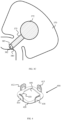
- FIG. 1 discloses a top view of the wearable apparatus, according to exemplary embodiments of the subject matter.
- the wearable apparatus 100 comprises electrical circuit 140 connected to a plurality of light-weight members 110, 112, 115 and 118. At least a portion of the plurality of light-weight members 110, 112, 115 and 118 is attached to an electrode on the bottom surface, said bottom surface points towards the patient's skin when in use.
- the bottom surface may be defined as an opposite direction from the electrical circuit 140.
- the light-weight members 110, 112, 115 and 118 may be made of fabric, or another light weight material selected from a group comprising cotton, paper, LDPE foil (Low Density Polyethylene), PET (Polyethylene terephthalate) foil, PU (Polyurethane) foil, polyester, silicone, nonwoven fabric, and a combination thereof.
- the light-weight members 110, 112, 115 and 118 may be multiple light-weight disposable members, while the electrical circuit is used multiple times.
- the two-side conductive passageway may also be defined as an electrical circuit board, such as a PCB, having circuitry in a both layers, a first layer facing the electrodes, and a second layer facing the electrical circuit 140.
- the conductive material such as the conductive ink, moves electrical signals between the first layer and the second layer.
- the light-weight disposable members 110, 112, 115 and 118 as disposable items also encourages manufacturing the light-weight disposable members 110, 112, 115 and 118 using printing technology, to reduce manufacture costs.
- printing technology may be screen (silk) printing, hot stamping, laser printing, offset printing, pad (tampon) printing and the like.
- the conductive element is attached to the bottom surface of the electrical circuit 140, and is connected to the electrode, as elaborated below.
- the light-weight disposable members 110, 112, 115 and 118 may be manufactured using laser engraving, forming the conductive members in the middle of the light-weight disposable members 110, 112, 115 and 118.
- the light-weight disposable members 110, 112, 115 and 118 may also be manufactured using mechanical press.
- the wearable apparatus 100 comprises some light-weight members that are not secured to one or more electrodes.
- light-weight members 110 and 115 are connected to one or more electrodes
- light-weight members 112 and 118 are not connected to electrodes and are part of the wearable apparatus 100 to improve grasping the apparatus 100 around the user's limb, for example the user's arm or leg.
- the wearable apparatus 100 also comprises a connecting member configured to secure the electrical circuit 140 to the light-weight members 110, 112, 115 and 118, thus securing the electrical circuit 140 to the conductive element that transfers the electrical information from the electrodes.
- the connecting member comprises multiple holders 130, 132, 135 and 138 configured to secure the housing of the electrical circuit 140.
- the multiple holders 130, 132, 135 and 138 may be secured to a lateral surface of the electrical circuit 140 or to a top surface of the electrical circuit 140.
- the connecting member is secured to the light-weight members 110, 112, 115 and 118 from the bottom section of the light-weight members 110, 112, 115 and 118, thus securing the housing of the electrical circuit 140 to the light-weight members 110, 112, 115 and 118.
- the multiple holders 130, 132, 135 and 138 may be made of a first holder member, which enables moving the holders away from the housing of the electrical circuit 140 when removing and securing the housing of the electrical circuit 140 on the connecting member.
- the first member may be located on the bottom side of the multiple holders 130, 132, 135 and 138, closer to the light-weight members 110, 112, 115 and 118.
- the multiple holders 130, 132, 135 and 138 may comprise a second member connected to the first member, said second member is more rigid and secures the electrical circuit 140 between the multiple holders 130, 132, 135 and 138.
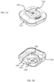
- FIGS 2A-2B show a top view and a bottom view of the electrical circuit, according to exemplary embodiments of the subject matter.
- the electrical circuit has a lateral surface 210, a top surface 220 and a bottom surface 260.
- the top surface 220 is accessible to the patient or medical professional, and may comprise an activation button 230, a display unit, a socket for connecting a cable to a display unit or another device and the like.
- the bottom section of the electrical circuit interfaces with the conductive element that transfers the electrical information from the electrodes.
- the bottom section comprises the bottom surface 260 and a secondary surface 270 that forms a specific form in the bottom surface. The form is configured to sit inside a niche in the connecting member, as elaborated below.
- the secondary surface 270 comprises one or more connectors 245, 250 configured to be secured to the conductive elements that pass the electrical information from the electrodes.
- the one or more connectors 245, 250 transfer the electrical information from the conductive elements into the electrical circuit located inside the housing.
- the one or more connectors 245, 250 may be pins, such as pogo pins, or a conductive surface, or a conductive spring leaves that connect on one end to the electrical circuit and on another end to the conductive members connected to the electrode.
- the one or more connectors 245, 250 are configured to be in physical contact with conductive areas 330, 332 of the top surface of the rigid frame 310 disclosed in figure 3 .
- the holders firmly secure the housing of the electrical circuit 140 to the body of the wearable device only when electrical conductivity is enabled between the one or more connectors 245, 250 and the conductive areas 330, 332 of the top surface of the rigid frame, said conductive areas are the output point of the conductive members that transfer electrical information from the one or more electrodes.
- the housing of the electrical circuit may be placed in a lower height, closer to the rigid frame, when the one or more connectors 245, 250 are in physical contact with the conductive areas 330, 332. The lower height of the housing of the electrical circuit enables firm secure of the holders.
- FIG. 3A shows a top view of a sensor module that comprises the multiple light-weight members, according to exemplary embodiments of the subject matter.
- the sensor module 300 comprises one or more electrodes (not shown) located on a bottom surface of the one or more light-weight members. For example, one electrode is located at the bottom of each light-weight member.
- the multiple light-weight members 335, 345, 355, 365 are all connected to a rigid frame 310 that surrounds a void 340.
- the void 340 is configured to accommodate the bottom surface 260 of the electrical circuit, while the secondary surface 270 resides on top of the rigid frame 310.
- the multiple light-weight members 335, 345, 355, 365 may be folded relative to the rigid frame 310 using an elastic connector configured to physically secure the multiple light-weight members 335, 345, 355, 365 to the rigid frame.
- the connector 350 secures the light-weight member 355 to the rigid frame 310.
- the rigid frame 310 is not fully surrounded by the connectors.
- lateral void 320 is provided between light-weight members 335 and 365. The void is configured to accommodate the holders of the connecting member.
- the rigid frame 310 comprises one or more conductive areas, such as conductive areas 330 and 332.
- the conductive areas 330 and 332 have a first side located on a frame top surface of the rigid frame 310 and a second side located on the frame bottom surface of the rigid frame 310.
- the second side located on the bottom surface of the rigid frame 310 is configured to be connected to the conductive members that pass electrical information from the electrodes.
- the first side of the conductive areas is configured to be secured to the one or more connectors 245, 250, that are connected to the electrical circuit.
- the conductive areas 330 and 332 are configured to pass the electrical information from the conductive members to the one or more connectors 245, 250 of the electrical circuit.
- Electrical information is passed from the first side of the conductive areas 330 and 332 to the second side using one or more apertures configured to contain a conductive fluid, for example conductive ink.
- the conductive ink may comprise ink mixed with silver, or any other metal.
- Other conductive fluids may be selected by a person skilled in the art.
- the one or more apertures enabling passage of the conductive fluid may be in the width of 0.05-0.4 millimeters, throughout the entire depth of the rigid frame 310.
- Figure 3B shows a bottom view of a sensor module that comprises the multiple light-weight members and the electrode, according to exemplary embodiments of the subject matter.
- the light-weight member 370 may be made of fabric, paper, polyethylene or any other light weight and collapsible material. Some examples to materials that can be used to manufacture the light-weight member 370 include thermoplastic elastomers, thermostatic elastomers, polyethylene sheets, polyester sheets, nonwoven fabric, PVC sheets, silicon sheets, wooden logs, paper sheets, LDPE, kapton sheets, sheets made of organic non-conductive materials, sheets for in-mold technology and a combination thereof.
- the light-weight member 370 have one or more pores enabling passage of the conductive material from the first layer to the second layer.
- An electrode 372 is attached to the bottom surface of the light-weight member 370.
- a conductive member 375 is connected to the electrode 372.
- the conductive member 375 is not in physical contact with the patient's skin.
- the conductive member 375 is connected to the bottom side 390 of the conductive area.
- the bottom side 390 comprises multiple apertures enabling passage of the conductive fluid as elaborated above.
- Figure 3C shows a zoom-in of the conductive area, according to exemplary embodiments of the subject matter.
- Figure 3C shows three apertures 380, 382 and 385, that extend from the bottom surface of the conductive area to the top surface of the conductive area.
- FIG. 4 shows a connecting member comprises multiple holders, according to exemplary embodiments of the subject matter.
- the connecting member 400 is configured to connect the electrical circuit to the light-weight members and secure the housing of the electrical circuit in place.
- the connecting member 400 comprises a connecting plate 420 configured to be secured to a bottom surface of the rigid frame 310 of the sensor module 300.
- the connecting member 400 is secured to the sensor module 300 from the bottom direction of the sensor module 300, while the housing of the electrical circuit is secured to the sensor module 300 from the upward direction of the sensor module 300.
- the upward direction may be defined as the side from which the electrodes are not seen.
- the connecting plate 420 has a connecting void 440 therein.
- the connecting void 440 may have substantially the same size and shape as the void 340 of the sensor module 300.
- the connecting void 440 may have a depth defined by the inner sidewalls 430 of the connecting plate 420.
- the connecting void 440 may have a higher depth than the depth of the void 340 of the sensor module 300.
- the connecting void 440 and the void 340 are configured to accommodate the bottom section of the housing of the electrical circuit, defined by the bottom surface 260.
- the connecting member 400 also comprises a plurality of holders 410, 412, 415 and 418, configured to secure the housing of the electrical circuit to the rigid frame of the sensor module 300.
- the plurality of holders 410, 412, 415 may be movable, for example move away from the center of the connecting void 440 when the housing is secured to the sensor module 300, or when the housing is removed therefrom.
- the plurality of holders 410, 412, 415 may be made of plastics or metal, and may comprise an elastic section, such as a spring, which is tensed when the holders move away from the connecting void 440.
- Said elastic section pushes the plurality of holders 410, 412, 415 back towards the center of the connecting void 440, thus securing the housing of the electrical circuit in place.
- the plurality of holders 410, 412, 415 move back into position only when there is electrical conductivity between the electrical circuit and the conductive element that carries the electrical information detected by the electrodes.
- FIG. 5 shows a bottom view of the wearable apparatus when assembled, according to exemplary embodiments of the subject matter.
- the wearable apparatus comprises the electrical circuit embodied in a housing secured to the sensor module using a connecting member.
- Figure 5 shows a bottom surface 555 of the housing.
- the bottom surface 555 is configured to be inserted into the connecting void of the connecting member as shown above.
- the connecting void is defined by frame 560, included in at least the sensor module.
- the wearable apparatus comprises multiple light-weight members 520, 522, 525 and 528. At least some of the light-weight members 520, 522, 525 and 528 are attached to an electrode in the bottom surface thereof, for example using biocompatible adhesive material, stitching, hooks and loops and the like.
- light-weight member 528 is attached to electrode 540 and light-weight member 522 is attached to electrode 545.
- the light-weight members leave lateral voids in the circumference of the frame from which the light weight members extend away from the frame's void.
- the lateral voids are consumed by a plurality of holders 510, 512, 515 and 518 configured to secure the housing in place.
- lateral void 570 is formed between light-weight member 522 and light-weight member 520, facilitating passage for holder 510.
- lateral void 572 is formed between light-weight member 522 and light-weight member 525, facilitating passage for holder 512
- lateral void 575 is formed between light-weight member 525 and light-weight member 528
- lateral void 578 is formed between light-weight member 528 and light-weight member 520, facilitating passage for holder 518.
- the light-weight members comprise a proximal side which is narrower than the distal side. For example, proximal side 535 of the light-weight member 520.
- Figures 6A-6B show a top view and a bottom view of the sensor module and the connecting module disassembled, according to exemplary embodiments of the subject matter.
- the top view shown in figure 6A discloses the four light-weight members, such as member 620, connected to the rigid frame 625.
- the rigid frame 625 comprises conductive areas 640 and 645, configured to be electrically coupled to the conductive elements 650, 655.
- the conductive elements 650, 655 are attached to the bottom surface of the light-weight members, in a manner that the patient is not in physical contact with the conductive elements 650, 655 when the wearable apparatus is placed on the patient's skin.
- the electrical information is collected by the electrodes 622, 623, transferred via the conductive elements 650, 655 towards the conductive areas 640 and 645, and to the electrical circuit that processes the electrical information or passes the electrical information to a device that processes the electrical information.
- the conductive elements 650, 655 are in proximity to the bottom surface of the rigid frame 660.
- the connecting frame of the connecting member 610 secures the conductive elements 650, 655 between the connecting frame and the rigid frame 660.
- the light-weight members have a distal side 611 of light weight member 613, and proximal side 612, located closer to the rigid frame 625.
- the proximal side 612 of the light weight member 613 is narrower than the distal side 611, leaving lateral voids such as 641, 642 that are consumed by the holders, such as holder 615 of the connecting member 610.
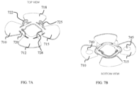
- Figures 7A-7B show a top view and a bottom view of the sensor module and the connecting module assembled, according to exemplary embodiments of the subject matter.
- Figure 7A shows a plurality of light-weight members 710, 712, 715 and 718, having therein the conductive members.
- the sensor module is attached to the connecting member having a plurality of holders 720, 722, 725 and 728.
- Figure 7B shows two electrodes 740, 745 attached to the bottom surface of the light-weight members 710 and 715, respectively.
- Step 810 discloses obtaining a sensor module, an electrical circuit embodied in a housing and a connecting member.
- the sensor module comprises one or more electrodes configured to collect electrical information from a patient's skin and pass the electrical information via a conductive element attached to the bottom surface of the light-weight member.
- the connecting member comprises a void configured to accommodate the bottom section of the housing of the electrical circuit and holders configured to secure the housing to the sensor module.
- Step 820 discloses securing the connecting member at a bottom side of the sensor module, thus securing the conductive elements.
- the conductive elements are secured between the frames of the sensor module and the connecting member, and pass electrical information via the conductive areas of the frame of the sensor module.
- the connecting member may be secured to the sensor module using mechanical clips.
- the connecting member secures only the housing of the electrical circuit, which electrically couples to the sensor module. Thus, the coupling of the housing and the sensor module form the connection between the connecting member and the sensor module.
- Step 830 discloses mounting the housing from the top section of the sensor module, secured by the holders of the connecting member.
- the holders are maneuvered away from the center of the void when placing the housing thereon. Then, the elastic member of the holders pushes the holders on the lateral surface of the housing.
- Step 840 discloses verifying electrical coupling between the conductivity members and the electrical circuit inside the housing. Such verifying may be performed by receiving an indication from the electrical circuit that electrical information is provided from the electrodes in a sufficient manner.
- the sufficient manner may be defined by predefined rules stored in the memory unit of the electrical circuit, for example receiving signals having properties in a predefined range.
Landscapes
- Health & Medical Sciences (AREA)
- Life Sciences & Earth Sciences (AREA)
- Surgery (AREA)
- Animal Behavior & Ethology (AREA)
- Pathology (AREA)
- Engineering & Computer Science (AREA)
- Biomedical Technology (AREA)
- Heart & Thoracic Surgery (AREA)
- Medical Informatics (AREA)
- Molecular Biology (AREA)
- Physics & Mathematics (AREA)
- Biophysics (AREA)
- General Health & Medical Sciences (AREA)
- Public Health (AREA)
- Veterinary Medicine (AREA)
- Cardiology (AREA)
- Dermatology (AREA)
- Nuclear Medicine, Radiotherapy & Molecular Imaging (AREA)
- Radiology & Medical Imaging (AREA)
- Measurement And Recording Of Electrical Phenomena And Electrical Characteristics Of The Living Body (AREA)
- Measuring And Recording Apparatus For Diagnosis (AREA)
Description
- The present disclosure generally relates to wearable devices, and more particularly relates to wearable devices for monitoring medical properties of patients.
- An electrocardiogram (ECG) is a tool used by physicians to diagnose heart problems and other potential health concerns. Diagnostic efficacy of problems, like syncope or cardiac arrhythmias, can be improved through the use of long-term extended wear ECG monitoring. Recording sufficient ECG and related physiological data over an extended period of time remains a significant challenge to healthcare providers, despite over a 40-year history of such efforts. Extended period monitoring essentially enables a physician to identify cardiac conditions, specifically, rhythm disorders, and other physiological events of potential concern.
- Wearable ECG devices are known from
US-2010/081913-A1 ,US-2008/288026-A1 ,US-2018/146877-A1 ,US-2015/351690-A1 ,US-2014/051946-A1 ,US-2015/374255-A1 ,US-9642537-B2 US-2017/188872-A1 . - Conventionally, maintaining continual contact between ECG electrodes and the skin after a day or two has been a problem. Time, dirt, moisture, and other environmental contaminants, as well as perspiration, skin oil, and dead skin cells from the patient's body, can get between an ECG electrode and the skin's surface. All of these factors adversely affect the quality of physical signal recordings. Furthermore, the physical movements of the patient and their clothing impart various compressional, tensile, and torsional forces on the contact point of an ECG electrode, especially over long recording times, and an inflexibly fastened ECG electrode will be prone to becoming dislodged. Moreover, dislodgment may occur unbeknownst to the patient, making the ECG recordings worthless Thus, it is desired to periodically remove or replace ECG electrodes during a long term ECG monitoring period, whether to replace a dislodged electrode, reestablish better adhesion, alleviate itching or irritation, allow for cleansing of the skin, allow for showering and exercise, or for other purpose. Such replacement or slight alteration in electrode location actually facilitates the goal of recording the ECG signal for long periods of time.
- The invention is defined by the claims.
- It is an object of the subject matter to disclose a wearable device for monitoring medical properties of a patient, comprising a body, comprising multiple light-weight disposable members, one or more electrodes located on a bottom surface of the multiple light-weight disposable members, wherein the one or more electrodes are configured to be in physical contact with a patient's skin and configured to collect electrical information from the patient's skin, an electrical circuit placed inside a housing, said housing is secured to an upper side of the multiple light-weight disposable members, said electrical circuit is configured to analyze the electrical information collected by the one or more electrodes, one or more conductive members, each conductive member of the one or more conductive members having a proximal side connected to the one or more electrodes and a distal side connected to the housing of the electrical circuit, and a connecting member coupled to lateral surface or top surface of the housing of the electrical circuit, configured to secure the electrical circuit to the body.
- In some cases, the electrical information collected from the patient's skin comprises ECG-related information. In some cases, the electrical circuit is configured to process the electrical information. The wearable device of claim 1, further comprises a housing for storing the electrical circuit, wherein the electrical circuit is configured to display ECG-related information on a top surface of the housing based on the electrical information collected from the patient's skin.
- In some cases, the bottom surface points towards the patient's skin when in use.
- In some cases, the light-weight disposable members are made of a material selected from a group comprising fabric, paper, Low Density Polyethylene, Polyethylene terephthalate, Polyurethane, polyester, silicone, nonwoven fabric and a combination thereof.
- The wearable device of claim 1, further comprising a two-side conductive passageway between the one or more electrodes located on the bottom surface of the light-weight disposable members and the electrical circuit is located upwards from the light-weight members.
- In some cases, the light-weight disposable members are manufactured using a printing technology. In some cases, the connecting member is secured to the light-weight disposable members from a bottom section of the light-weight disposable members.
- In some cases, the electrical circuit comprises a bottom section comprises a bottom surface and a secondary surface, said secondary surface forms a specific form in the bottom section, wherein the form is configured to sit inside a niche in the connecting member.
- In some cases, the multiple light-weight disposable members are connected to a rigid frame that surrounds a void, wherein the void is configured to accommodate the bottom surface of the electrical circuit. In some cases, the multiple light-weight disposable members are foldable relative to the rigid frame using an elastic connector configured to physically secure the multiple light-weight disposable members to the rigid frame.
- In some cases, the rigid frame comprises a frame bottom surface configured to be connected to the one or more conductive members that pass electrical information from the one or more electrodes and a frame top surface comprising one or more conductive areas configured to be secured to connectors connected to the housing of the electrical circuit.
- In some cases, the electrical information passed from the first side of the one or more conductive areas to the second side using one or more apertures configured to contain a conductive fluid. In some cases, the conductive fluid comprises conductive ink.
- In some cases, the one or more conductive members are connected to a bottom side of the one or more conductive areas, said bottom side of the one or more conductive areas comprises multiple apertures enabling passage of the conductive fluid as elaborated above.
- In some cases, the housing of the electrical circuit comprises one or more connectors configured to be secured to the one or more conductive members that pass the electrical information from the one or more electrodes.
- In some cases, the one or more connectors connect on one end to the housing of the electrical circuit and on another end to the one or more conductive members connected to the electrode.
- In some cases, the connecting member secures the housing of the electrical circuit to the body only when electrical conductivity is enabled between the one or more connectors and the one or more conductive members. In some cases, the connecting member comprises a plurality of holders secured to a lateral surface or a top surface of the electrical circuit.
- In some cases, the plurality of holders comprise an elastic section, wherein the elastic section is tensed when the plurality of holders move away from the connecting void.
- In some cases, the light-weight disposable members comprise a distal side and a proximal side, said proximal side is narrower than the distal side, thereby forming lateral voids between the light-weight disposable members.
- The invention may be more clearly understood upon reading of the following detailed description of non-limiting exemplary embodiments thereof, with reference to the following drawings, in which:
-
Figure 1 discloses a top view of the wearable apparatus, according to exemplary embodiments of the subject matter; -
Figures 2A-2B show a top view and a bottom view of the electrical circuit, according to exemplary embodiments of the subject matter; -
Figure 3A shows a top view of a sensor module that comprises the multiple light-weight members, according to exemplary embodiments of the subject matter; -
Figure 3B shows a bottom view of a sensor module that comprises the multiple light-weight members and the electrode, according to exemplary embodiments of the subject matter; -
Figure 3C shows a zoom-in of the conductive area, according to exemplary embodiments of the subject matter; -
Figure 4 shows a connecting member comprises multiple holders, according to exemplary embodiments of the subject matter; -
Figure 5 shows a bottom view of the wearable apparatus when assembled, according to exemplary embodiments of the subject matter; -
Figures 6A-6B show a top view and a bottom view of the sensor module and the connecting module disassembled, according to exemplary embodiments of the subject matter; -
Figures 7A-7B show a top view and a bottom view of the sensor module and the connecting module assembled, according to exemplary embodiments of the subject matter; and, -
Figure 8 shows a method for assembling a wearable device, according to exemplary embodiments of the subject matter. - The following detailed description of embodiments of the invention refers to the accompanying drawings referred to above. Dimensions of components and features shown in the figures are chosen for convenience or clarity of presentation and are not necessarily shown to scale. Wherever possible, the same reference numbers will be used throughout the drawings and the following description to refer to the same and like parts.
- Illustrative embodiments of the invention are described below. In the interest of clarity, not all features/components of an actual implementation are necessarily described.
- The present invention discloses a wearable device for monitoring medical properties of a patient, either a person or animal. The wearable device comprises one or more electrodes configured to be secured and attached to the patient's skin and an electrical circuit connected to the one or more electrodes. The one or more electrodes are configured to collect electrical information from the patient's skin, for example ECG-related information such as blood pressure and the like. The one or more electrodes are an optional embodiment for the wearable device of the disclosed subject matter. The wearable device may comprise a camera or any other type of sensor configured to collect medical information from the patient's skin. The sensor may comprise a light emitter for emitting light towards the patient's skin and a collector for collecting the reflections from the patient's skin. The electrical information may include voltage, frequency, amplitude, conductivity and the like. The electrical information is passed to the electrical circuit via a conductive member connected to the one or more electrode. The electrical circuit may transmit the electrical information to a remote device. The electrical circuit may process the electrical information and display ECG-related information such as blood pressure, trends and the like.
- The wearable device of the subject matter comprises a body having multiple light-weight disposable members. The one or more electrodes are physically attached to the multiple light-weight members. The multiple light-weight disposable members are configured to be secured to the patient's skin. The conductive member is attached to a bottom surface of the light-weight member and then connects to the electrical circuit, via a housing of the electrical circuit. This way, the electrical circuit is isolated from the patient's skin and the user's experience is improved.
-
FIG. 1 discloses a top view of the wearable apparatus, according to exemplary embodiments of the subject matter. Thewearable apparatus 100 compriseselectrical circuit 140 connected to a plurality of light-weight members weight members electrical circuit 140. The light-weight members weight members weight members electrical circuit 140 located upwards from the light-weight members110, 112, 115 and 118. The two-side conductive passageway may also be defined as an electrical circuit board, such as a PCB, having circuitry in a both layers, a first layer facing the electrodes, and a second layer facing theelectrical circuit 140. The conductive material, such as the conductive ink, moves electrical signals between the first layer and the second layer. - Defining the light-weight
disposable members disposable members electrical circuit 140, and is connected to the electrode, as elaborated below. In some other cases, the light-weightdisposable members disposable members disposable members - In some exemplary cases, the
wearable apparatus 100 comprises some light-weight members that are not secured to one or more electrodes. For example, light-weight members weight members wearable apparatus 100 to improve grasping theapparatus 100 around the user's limb, for example the user's arm or leg. - The
wearable apparatus 100 also comprises a connecting member configured to secure theelectrical circuit 140 to the light-weight members electrical circuit 140 to the conductive element that transfers the electrical information from the electrodes. The connecting member comprisesmultiple holders electrical circuit 140. Themultiple holders electrical circuit 140 or to a top surface of theelectrical circuit 140. In some exemplary cases, the connecting member is secured to the light-weight members weight members electrical circuit 140 to the light-weight members multiple holders electrical circuit 140 when removing and securing the housing of theelectrical circuit 140 on the connecting member. The first member may be located on the bottom side of themultiple holders weight members multiple holders electrical circuit 140 between themultiple holders -
Figures 2A-2B show a top view and a bottom view of the electrical circuit, according to exemplary embodiments of the subject matter. The electrical circuit has alateral surface 210, atop surface 220 and abottom surface 260. Thetop surface 220 is accessible to the patient or medical professional, and may comprise anactivation button 230, a display unit, a socket for connecting a cable to a display unit or another device and the like. The bottom section of the electrical circuit interfaces with the conductive element that transfers the electrical information from the electrodes. The bottom section comprises thebottom surface 260 and asecondary surface 270 that forms a specific form in the bottom surface. The form is configured to sit inside a niche in the connecting member, as elaborated below. Thesecondary surface 270 comprises one ormore connectors more connectors more connectors more connectors conductive areas rigid frame 310 disclosed infigure 3 . In some exemplary embodiments of the subject matter, the holders firmly secure the housing of theelectrical circuit 140 to the body of the wearable device only when electrical conductivity is enabled between the one ormore connectors conductive areas more connectors conductive areas - The electrical circuit may comprise a memory unit configured to store a set of instructions, for example instructions configured to convert the electrical information collected by the electrodes into signals that represent medical information. The electrical circuit comprises a processing module configured to control the process of converting the electrical information into signals and may also perform more advanced processes, such as identifying trends in the collected medical information, identifying irregularities in the medical information and the like. The electrical circuit may be implemented as a printed circuit board or in any other manner in which electrical components are arranged in a predefined volume, as desired by a person skilled in the art.
-
Figure 3A shows a top view of a sensor module that comprises the multiple light-weight members, according to exemplary embodiments of the subject matter. Thesensor module 300 comprises one or more electrodes (not shown) located on a bottom surface of the one or more light-weight members. For example, one electrode is located at the bottom of each light-weight member. The multiple light-weight members rigid frame 310 that surrounds avoid 340. Thevoid 340 is configured to accommodate thebottom surface 260 of the electrical circuit, while thesecondary surface 270 resides on top of therigid frame 310. The multiple light-weight members rigid frame 310 using an elastic connector configured to physically secure the multiple light-weight members connector 350 secures the light-weight member 355 to therigid frame 310. It should be noted that therigid frame 310 is not fully surrounded by the connectors. For example,lateral void 320 is provided between light-weight members - The
rigid frame 310 comprises one or more conductive areas, such asconductive areas conductive areas rigid frame 310 and a second side located on the frame bottom surface of therigid frame 310. The second side located on the bottom surface of therigid frame 310 is configured to be connected to the conductive members that pass electrical information from the electrodes. The first side of the conductive areas is configured to be secured to the one ormore connectors conductive areas more connectors conductive areas rigid frame 310. -
Figure 3B shows a bottom view of a sensor module that comprises the multiple light-weight members and the electrode, according to exemplary embodiments of the subject matter. The light-weight member 370 may be made of fabric, paper, polyethylene or any other light weight and collapsible material. Some examples to materials that can be used to manufacture the light-weight member 370 include thermoplastic elastomers, thermostatic elastomers, polyethylene sheets, polyester sheets, nonwoven fabric, PVC sheets, silicon sheets, wooden logs, paper sheets, LDPE, kapton sheets, sheets made of organic non-conductive materials, sheets for in-mold technology and a combination thereof. The light-weight member 370 have one or more pores enabling passage of the conductive material from the first layer to the second layer. Anelectrode 372 is attached to the bottom surface of the light-weight member 370. Aconductive member 375 is connected to theelectrode 372. Theconductive member 375 is not in physical contact with the patient's skin. Theconductive member 375 is connected to thebottom side 390 of the conductive area. Thebottom side 390 comprises multiple apertures enabling passage of the conductive fluid as elaborated above. -
Figure 3C shows a zoom-in of the conductive area, according to exemplary embodiments of the subject matter.Figure 3C shows threeapertures -
Figure 4 shows a connecting member comprises multiple holders, according to exemplary embodiments of the subject matter. The connectingmember 400 is configured to connect the electrical circuit to the light-weight members and secure the housing of the electrical circuit in place. The connectingmember 400 comprises a connectingplate 420 configured to be secured to a bottom surface of therigid frame 310 of thesensor module 300. The connectingmember 400 is secured to thesensor module 300 from the bottom direction of thesensor module 300, while the housing of the electrical circuit is secured to thesensor module 300 from the upward direction of thesensor module 300. The upward direction may be defined as the side from which the electrodes are not seen. In some exemplary cases, the connectingplate 420 has a connectingvoid 440 therein. The connectingvoid 440 may have substantially the same size and shape as thevoid 340 of thesensor module 300. The connectingvoid 440 may have a depth defined by theinner sidewalls 430 of the connectingplate 420. The connectingvoid 440 may have a higher depth than the depth of thevoid 340 of thesensor module 300. The connectingvoid 440 and the void 340 are configured to accommodate the bottom section of the housing of the electrical circuit, defined by thebottom surface 260. - The connecting
member 400 also comprises a plurality ofholders sensor module 300. The plurality ofholders void 440 when the housing is secured to thesensor module 300, or when the housing is removed therefrom. The plurality ofholders void 440. Said elastic section pushes the plurality ofholders void 440, thus securing the housing of the electrical circuit in place. In some exemplary cases, the plurality ofholders -
Figure 5 shows a bottom view of the wearable apparatus when assembled, according to exemplary embodiments of the subject matter. The wearable apparatus comprises the electrical circuit embodied in a housing secured to the sensor module using a connecting member.Figure 5 shows abottom surface 555 of the housing. Thebottom surface 555 is configured to be inserted into the connecting void of the connecting member as shown above. The connecting void is defined byframe 560, included in at least the sensor module. The wearable apparatus comprises multiple light-weight members weight members weight member 528 is attached toelectrode 540 and light-weight member 522 is attached toelectrode 545. The light-weight members leave lateral voids in the circumference of the frame from which the light weight members extend away from the frame's void. The lateral voids are consumed by a plurality ofholders lateral void 570 is formed between light-weight member 522 and light-weight member 520, facilitating passage forholder 510. Similarly,lateral void 572 is formed between light-weight member 522 and light-weight member 525, facilitating passage forholder 512,lateral void 575 is formed between light-weight member 525 and light-weight member 528, facilitating passage forholder 515 andlateral void 578 is formed between light-weight member 528 and light-weight member 520, facilitating passage forholder 518. The light-weight members comprise a proximal side which is narrower than the distal side. For example,proximal side 535 of the light-weight member 520. -
Figures 6A-6B show a top view and a bottom view of the sensor module and the connecting module disassembled, according to exemplary embodiments of the subject matter. The top view shown infigure 6A discloses the four light-weight members, such asmember 620, connected to therigid frame 625. Therigid frame 625 comprisesconductive areas conductive elements conductive elements conductive elements electrodes conductive elements conductive areas conductive elements rigid frame 660. The connecting frame of the connectingmember 610 secures theconductive elements rigid frame 660. The light-weight members have adistal side 611 oflight weight member 613, andproximal side 612, located closer to therigid frame 625. Theproximal side 612 of thelight weight member 613 is narrower than thedistal side 611, leaving lateral voids such as 641, 642 that are consumed by the holders, such asholder 615 of the connectingmember 610. -
Figures 7A-7B show a top view and a bottom view of the sensor module and the connecting module assembled, according to exemplary embodiments of the subject matter.Figure 7A shows a plurality of light-weight members holders Figure 7B shows twoelectrodes weight members -
Figure 8 shows a method for assembling a wearable device, according to exemplary embodiments of the subject matter. Step 810 discloses obtaining a sensor module, an electrical circuit embodied in a housing and a connecting member. The sensor module comprises one or more electrodes configured to collect electrical information from a patient's skin and pass the electrical information via a conductive element attached to the bottom surface of the light-weight member. The connecting member comprises a void configured to accommodate the bottom section of the housing of the electrical circuit and holders configured to secure the housing to the sensor module. - Step 820 discloses securing the connecting member at a bottom side of the sensor module, thus securing the conductive elements. The conductive elements are secured between the frames of the sensor module and the connecting member, and pass electrical information via the conductive areas of the frame of the sensor module. The connecting member may be secured to the sensor module using mechanical clips. In some other cases, the connecting member secures only the housing of the electrical circuit, which electrically couples to the sensor module. Thus, the coupling of the housing and the sensor module form the connection between the connecting member and the sensor module.
- Step 830 discloses mounting the housing from the top section of the sensor module, secured by the holders of the connecting member. The holders are maneuvered away from the center of the void when placing the housing thereon. Then, the elastic member of the holders pushes the holders on the lateral surface of the housing.
- Step 840 discloses verifying electrical coupling between the conductivity members and the electrical circuit inside the housing. Such verifying may be performed by receiving an indication from the electrical circuit that electrical information is provided from the electrodes in a sufficient manner. The sufficient manner may be defined by predefined rules stored in the memory unit of the electrical circuit, for example receiving signals having properties in a predefined range.
- While the disclosure has been described with reference to exemplary embodiments, it will be understood by those skilled in the art that various changes may be made and equivalents may be substituted for elements thereof without departing from the scope of the invention. In addition, many modifications may be made to adapt a particular situation or material to the teachings without departing from the essential scope thereof. Therefore, it is intended that the disclosed subject matter not be limited to the particular embodiment disclosed as the best mode contemplated for carrying out this invention, but only by the claims that follow.
Claims (12)
- A wearable device (100) for monitoring medical properties of a patient, comprising:a sensor module (300), comprising:multiple light-weight disposable members (335,345,355,365) connected to a rigid frame (310);one or more electrodes (372) located on a bottom surface of the multiple light-weight disposable members (335,345,355,365), wherein the one or more electrodes (372) are configured to be in physical contact with a patient's skin and configured to collect electrical information from the patient's skin; andone or more conductive members (375), each conductive member of the one or more conductive members (375) having a proximal side connected to the one or more electrodes (372);an electrical circuit (140) placed inside a housing, said housing is secured to the rigid frame (310), said electrical circuit (140) is configured to analyze the electrical information collected by the one or more electrodes (372); anda connecting member (400) coupled to lateral surface (210) or top surface (220) of the housing of the electrical circuit (140), configured to secure the housing of the electrical circuit (140) to the sensor module (300), each conductive member of the one or more conductive members (375) having a distal side connected to the housing of the electrical circuit (140) when the housing of the electrical circuit (140) is secured to the sensor module (300),wherein:the electrical circuit (140) comprises a bottom section comprising a bottom surface (260) and a secondary surface (270), said secondary surface (270) forms a specific form in the bottom section, wherein the form is configured to sit inside a niche (440) in the connecting member (400);the rigid frame (310) surrounds a void (340), wherein the void (340) is configured to accommodate the bottom surface (260) of the electrical circuit (140); andthe rigid frame (310) comprises a frame bottom surface, a frame top surface and one or more conductive areas (330,332) having a first side located on the frame top surface and a second side (390) located on the frame bottom surface, the first side of the one or more conductive areas (330,332) being configured to be secured to connectors (245,250) connected to the housing of the electrical circuit (140) and the second side (390) being configured to be connected to the one or more conductive members (375) that pass electrical information from the one or more electrodes (372), wherein the electrical information is passed to the first side of the one or more conductive areas (330,332) from the second side (390) using one or more apertures configured to contain a conductive fluid.
- The wearable device (100) of claim 1, wherein the electrical information collected from the patient's skin comprises ECG-related information.
- The wearable device (100) of claim 1, wherein the electrical circuit is configured to display ECG-related information on a top surface (220) of the housing based on the electrical information collected from the patient's skin.
- The wearable device (100) of claim 1, further comprising a two-side conductive passageway between the one or more electrodes (372) located on the bottom surface of the light-weight disposable members (335,345,355,365) and the electrical circuit (140) is located upwards from the light-weight disposable members (335,345,355,365).
- The wearable device (100) of claim 1, wherein the multiple light-weight disposable members (335,345,355,365) are foldable relative to the rigid frame (310) using an elastic connector (350) configured to physically secure the multiple light-weight disposable members (335,345,355,365) to the rigid frame (310).
- The wearable device (100) of claim 1, wherein the one or more conductive members (375) are connected to a bottom side of the one or more conductive areas (330,332), said bottom side of the one or more conductive areas (330,332) comprises multiple apertures enabling passage of the conductive fluid.
- The wearable device (100) of claim 1, wherein the housing of the electrical circuit (140) comprises one or more connectors (245,250) configured to be secured to the one or more conductive members (375) that pass the electrical information from the one or more electrodes (372).
- The wearable device (100) of claim 7, wherein the one or more connectors (245,250) connect on one end to the housing of the electrical circuit (140) and on another end to the one or more conductive members (375) connected to the electrode.
- The wearable device (100) of claim 7, wherein the connecting member (400) secures the housing of the electrical circuit (140) to the sensor module (300) only when electrical conductivity is enabled between the one or more connectors (245,250) and the one or more conductive members (375).
- The wearable device (100) of claim 1, wherein the connecting member (400) comprises a plurality of holders (410,412,415,418) secured to a lateral surface (210) or a top surface (220) of the electrical circuit (140).
- The wearable device (100) of claim 10, wherein the plurality of holders (410,412,415,418) comprise an elastic section, wherein the elastic section is tensed when the plurality of holders (410,412,415,418) move away from the connecting void.
- The wearable device (100) of claim 1, wherein the light-weight disposable members (335,345,355,365) comprise a distal side and a proximal side, said proximal side is narrower than the distal side, thereby forming lateral voids (320) between the light-weight disposable members (335,345,355,365).
Applications Claiming Priority (2)
| Application Number | Priority Date | Filing Date | Title |
|---|---|---|---|
| US201862758642P | 2018-11-11 | 2018-11-11 | |
| PCT/IL2019/051204 WO2020095296A1 (en) | 2018-11-11 | 2019-11-04 | Wearable apparatus and method for monitoring medical properties |
Publications (3)
| Publication Number | Publication Date |
|---|---|
| EP3876830A1 EP3876830A1 (en) | 2021-09-15 |
| EP3876830A4 EP3876830A4 (en) | 2022-08-24 |
| EP3876830B1 true EP3876830B1 (en) | 2025-06-25 |
Family
ID=70611783
Family Applications (1)
| Application Number | Title | Priority Date | Filing Date |
|---|---|---|---|
| EP19881827.0A Active EP3876830B1 (en) | 2018-11-11 | 2019-11-04 | Wearable apparatus and method for monitoring medical properties |
Country Status (4)
| Country | Link |
|---|---|
| US (2) | US20220015681A1 (en) |
| EP (1) | EP3876830B1 (en) |
| CN (1) | CN113260302B (en) |
| WO (1) | WO2020095296A1 (en) |
Families Citing this family (18)
| Publication number | Priority date | Publication date | Assignee | Title |
|---|---|---|---|---|
| EP3344123B1 (en) | 2015-08-31 | 2022-10-26 | Masimo Corporation | Wireless patient monitoring methods |
| US11076777B2 (en) | 2016-10-13 | 2021-08-03 | Masimo Corporation | Systems and methods for monitoring orientation to reduce pressure ulcer formation |
| CN113260302B (en) | 2018-11-11 | 2024-08-16 | 拜尔比特技术公司 | Wearable device and method for monitoring medical characteristics |
| EP4003501B1 (en) * | 2019-07-31 | 2026-01-21 | Med-El Elektromedizinische Geraete GmbH | Printed tattoo electrode respiration sensor for laryngeal pacemakers |
| CN115243617B (en) | 2019-12-23 | 2025-10-28 | 测验有限公司 | Electrode patches and connection systems |
| US10813578B1 (en) | 2019-12-26 | 2020-10-27 | Biobeat Technologies Ltd. | Sensor device for optical measurement of biological properties |
| WO2021188999A2 (en) | 2020-03-20 | 2021-09-23 | Masimo Corporation | Health monitoring system for limiting the spread of an infection in an organization |
| US12635894B2 (en) | 2020-06-11 | 2026-05-26 | Biobeat Technologies Ltd. | Sensor device to mitigate the effects of unwanted signals made in optical measurements of biological properties |
| USD974193S1 (en) * | 2020-07-27 | 2023-01-03 | Masimo Corporation | Wearable temperature measurement device |
| USD980091S1 (en) | 2020-07-27 | 2023-03-07 | Masimo Corporation | Wearable temperature measurement device |
| USD1072837S1 (en) | 2020-10-27 | 2025-04-29 | Masimo Corporation | Display screen or portion thereof with graphical user interface |
| CN118510440A (en) | 2021-09-22 | 2024-08-16 | 迈心诺公司 | Wearable device for noninvasive body temperature measurement |
| USD1000975S1 (en) * | 2021-09-22 | 2023-10-10 | Masimo Corporation | Wearable temperature measurement device |
| EP4272627B1 (en) | 2022-05-04 | 2024-10-30 | CardioMedive Healthcare SRL | Medical device for monitoring health parameters of a patient and method of monitoring health parameters of a patient |
| USD1048908S1 (en) | 2022-10-04 | 2024-10-29 | Masimo Corporation | Wearable sensor |
| DE102023113156A1 (en) * | 2023-05-18 | 2024-11-21 | Raphael Lang GbR (vertretungsberechtigter Gesellschafter: Raphael Patrick Manfred Lang, 72631 Aichtal) | Portable device |
| JPWO2025028451A1 (en) * | 2023-08-01 | 2025-02-06 | ||
| USD1101156S1 (en) * | 2024-01-09 | 2025-11-04 | VIVAQUANT, Inc | Monitoring apparatus |
Family Cites Families (183)
| Publication number | Priority date | Publication date | Assignee | Title |
|---|---|---|---|---|
| FR2105327A5 (en) | 1970-09-01 | 1972-04-28 | Robillard Jean | Pressure gauge - esp for blood, using a liquid crystal |
| US3973129A (en) | 1975-01-10 | 1976-08-03 | Bell Telephone Laboratories, Incorporated | Fluorimetric apparatus and method for analysis of body fluid |
| US4659923A (en) | 1981-03-09 | 1987-04-21 | Polaroid Corporation | Fiber optic interferometer transducer |
| US4703758A (en) | 1982-09-30 | 1987-11-03 | Yoshiaki Omura | Non-invasive monitoring of blood flow and cerebral blood pressure using ultra miniature reflection type photoelectric plethysmographic sensors or ultrasonic doppler flow meter |
| US4901728A (en) | 1988-05-31 | 1990-02-20 | Eol, Inc. | Personal glucose monitor |
| SE465551B (en) | 1990-02-16 | 1991-09-30 | Aake Oeberg | DEVICE FOR DETERMINING A HEART AND RESPIRATORY FREQUENCY THROUGH PHOTOPLETISMOGRAPHICAL SEATING |
| EP0443267A1 (en) | 1990-02-23 | 1991-08-28 | Sentinel Monitoring, Inc. | Method and apparatus for continuous non-invasive blood pressure monitoring |
| US5209231A (en) | 1990-11-02 | 1993-05-11 | University Of Connecticut | Optical glucose sensor apparatus and method |
| US5273036A (en) | 1991-04-03 | 1993-12-28 | Ppg Industries, Inc. | Apparatus and method for monitoring respiration |
| US5672875A (en) | 1992-07-15 | 1997-09-30 | Optix Lp | Methods of minimizing scattering and improving tissue sampling in non-invasive testing and imaging |
| DE4242232C2 (en) | 1992-12-15 | 1998-12-10 | Burkhard Kuhls | Device and method for the non-invasive determination of the concentration of polarizing substances in the human body |
| US5377673A (en) | 1993-03-22 | 1995-01-03 | Van Dell; Peter | Intrauterine monitoring device |
| DE4446390C1 (en) | 1994-12-23 | 1996-07-04 | Siemens Ag | Method and device for measuring the concentration of an analyte contained in a sample |
| US6152876A (en) | 1997-04-18 | 2000-11-28 | Rio Grande Medical Technologies, Inc. | Method for non-invasive blood analyte measurement with improved optical interface |
| US5800348A (en) | 1995-08-31 | 1998-09-01 | Hewlett-Packard Company | Apparatus and method for medical monitoring, in particular pulse oximeter |
| US6027452A (en) | 1996-06-26 | 2000-02-22 | Vital Insite, Inc. | Rapid non-invasive blood pressure measuring device |
| DE19628562A1 (en) | 1996-07-16 | 1998-01-22 | Boehringer Mannheim Gmbh | Optical system evaluating quality of fluid distribution onto test piece, e.g. medical test strip |
| US5868671A (en) | 1997-01-28 | 1999-02-09 | Hewlett-Packard Company | Multiple ECG electrode strip |
| GB2357845B (en) | 1997-03-07 | 2001-09-19 | Optel Instr Ltd | Biological measurement system |
| IL121079A0 (en) | 1997-06-15 | 1997-11-20 | Spo Medical Equipment Ltd | Physiological stress detector device and method |
| US6041246A (en) | 1997-10-14 | 2000-03-21 | Transonic Systems, Inc. | Single light sensor optical probe for monitoring blood parameters and cardiovascular measurements |
| US20050096513A1 (en) | 1997-11-11 | 2005-05-05 | Irvine Sensors Corporation | Wearable biomonitor with flexible thinned integrated circuit |
| US6505059B1 (en) | 1998-04-06 | 2003-01-07 | The General Hospital Corporation | Non-invasive tissue glucose level monitoring |
| EP1083822A4 (en) | 1998-06-11 | 2005-10-12 | S P O Medical Equipment Ltd | Physiological stress detector device and method |
| US6491647B1 (en) | 1998-09-23 | 2002-12-10 | Active Signal Technologies, Inc. | Physiological sensing device |
| US6148232A (en) | 1998-11-09 | 2000-11-14 | Elecsys Ltd. | Transdermal drug delivery and analyte extraction |
| US7006855B1 (en) | 1998-11-16 | 2006-02-28 | S.P.O. Medical Equipment Ltd. | Sensor for radiance based diagnostics |
| AU1175600A (en) | 1998-11-16 | 2000-06-05 | S.P.O. Medical Equipment Ltd. | A sensor for radiance based diagnostics |
| US6556851B1 (en) | 1998-12-07 | 2003-04-29 | Lea Medizintechnik Gmbh | Detection probe for optical spectroscopy and spectrometry |
| US6134458A (en) | 1998-12-15 | 2000-10-17 | Futrex Inc. | Light probe for a near-infrared body chemistry measurement instrument |
| WO2000043536A1 (en) | 1999-01-22 | 2000-07-27 | University Of Maryland, Baltimore | Glucose sensing using metal-ligand complexes |
| WO2000060350A2 (en) | 1999-04-01 | 2000-10-12 | University Of Connecticut | Optical glucose sensor apparatus and method for the optical detektion of glucose |
| US6252032B1 (en) | 1999-07-07 | 2001-06-26 | Minimed Inc. | UV absorbing polymer |
| EP1210009A1 (en) | 1999-09-08 | 2002-06-05 | Optoq AB | Method and apparatus for detecting blood characteristics including hemoglobin |
| CA2388033A1 (en) | 1999-10-07 | 2001-04-12 | Alexander K. Mills | Device and method for noninvasive continuous determination of physiologic characteristics |
| US7359741B2 (en) | 1999-11-15 | 2008-04-15 | Spo Medical Equipment Ltd. | Sensor and radiance based diagnostics |
| FI19992484L (en) | 1999-11-22 | 2001-05-23 | Polar Electro Oy | Method for performing operational settings of a heart rate measurement arrangement and heart rate measurement arrangement |
| EP1237470A4 (en) | 1999-12-17 | 2006-04-26 | Datex Ohmeda Inc | Method and system for improving photoplethysmographic analyte measurements by de-weighting motion-contaminated data |
| WO2001053806A1 (en) | 2000-01-18 | 2001-07-26 | Radiometer Medical A/S | Apparatus, sample cuvette and method for optical measurements |
| US6434420B1 (en) | 2000-01-31 | 2002-08-13 | Integrated Biosensing Technologies | Biopotential electrode sensory component |
| US7171251B2 (en) | 2000-02-01 | 2007-01-30 | Spo Medical Equipment Ltd. | Physiological stress detector device and system |
| IL152300A0 (en) | 2000-04-17 | 2003-05-29 | Vivometrics Inc | Systems and methods for ambulatory monitoring of physiological signs |
| US6616613B1 (en) | 2000-04-27 | 2003-09-09 | Vitalsines International, Inc. | Physiological signal monitoring system |
| US6784981B1 (en) | 2000-06-02 | 2004-08-31 | Idexx Laboratories, Inc. | Flow cytometry-based hematology system |
| US20020099277A1 (en) | 2000-09-12 | 2002-07-25 | Nexan Limited | Disposable vital signs monitoring sensor band with removable alignment sheet |
| US20100276733A1 (en) | 2000-09-27 | 2010-11-04 | Li Choa H | Solid-state circuit device |
| US20040030258A1 (en) | 2000-10-09 | 2004-02-12 | Williams Christopher Edward | Sensor assembly for monitoring an infant brain |
| US6618138B2 (en) | 2000-10-12 | 2003-09-09 | Jed Khoury | Scanning fluorescent systems for various diagnostic |
| US7470420B2 (en) | 2000-12-05 | 2008-12-30 | The Regents Of The University Of California | Optical determination of glucose utilizing boronic acid adducts |
| WO2003096876A2 (en) | 2001-04-01 | 2003-11-27 | Sommer Phillipe L | Continuously operational diagnostic device |
| US6704588B2 (en) | 2001-06-16 | 2004-03-09 | Rafat R. Ansari | Method and apparatus for the non-invasive measurement of blood glucose levels in humans |
| US6836337B2 (en) | 2001-09-20 | 2004-12-28 | Visual Pathways, Inc. | Non-invasive blood glucose monitoring by interferometry |
| US20040111035A1 (en) | 2001-11-06 | 2004-06-10 | Kasuya Kondoh | Instrument for measuring biological information and method for measuring biological information |
| US20030149349A1 (en) | 2001-12-18 | 2003-08-07 | Jensen Thomas P. | Integral patch type electronic physiological sensor |
| US6825928B2 (en) | 2001-12-19 | 2004-11-30 | Wisconsin Alumni Research Foundation | Depth-resolved fluorescence instrument |
| DE10163972B4 (en) | 2001-12-22 | 2005-10-27 | Roche Diagnostics Gmbh | Method and device for determining a light transport parameter and an analyte in a biological matrix |
| JP3966796B2 (en) | 2002-09-26 | 2007-08-29 | 真人 中村 | Blood glucose measuring device |
| EP1936356A1 (en) | 2002-10-29 | 2008-06-25 | Bayer HealthCare LLC | Diffuse reflectance readhead |
| US7623906B2 (en) | 2002-11-12 | 2009-11-24 | Inlight Solutions, Inc | Diffuse reflectance spectroscopy |
| JP4408640B2 (en) | 2003-03-17 | 2010-02-03 | 興和株式会社 | Ophthalmic measuring device |
| DE602004030549D1 (en) | 2003-04-04 | 2011-01-27 | Lumidigm Inc | MULTISPEKTRALBIOMETRIESENSOR |
| DE10329915A1 (en) | 2003-07-02 | 2005-03-17 | Manfred Holtkamp Elektronik Gmbh | Devices and methods for the determination of a permissible irradiation of the human skin with UV radiation |
| IL164030A0 (en) | 2003-09-12 | 2005-12-18 | Revital Pery Shechter | Photoacoustic analyzer of a region of interest in a human body |
| US8135447B2 (en) | 2003-10-02 | 2012-03-13 | Panasonic Electric Works Co., Ltd. | Optical biological information measuring apparatus, optical biological information measuring method, biological information decision apparatus, program and recording medium |
| US20050113661A1 (en) | 2003-11-21 | 2005-05-26 | Alireza Nazeri | EKG recording accessory system (EKG RAS) |
| US20070118054A1 (en) | 2005-11-01 | 2007-05-24 | Earlysense Ltd. | Methods and systems for monitoring patients for clinical episodes |
| US10194810B2 (en) | 2004-02-05 | 2019-02-05 | Earlysense Ltd. | Monitoring a condition of a subject |
| US8491492B2 (en) | 2004-02-05 | 2013-07-23 | Earlysense Ltd. | Monitoring a condition of a subject |
| US8942779B2 (en) | 2004-02-05 | 2015-01-27 | Early Sense Ltd. | Monitoring a condition of a subject |
| JP4809779B2 (en) | 2004-02-05 | 2011-11-09 | アーリーセンス・リミテッド | Prediction and monitoring technology for clinical onset in respiration |
| US9131891B2 (en) | 2005-11-01 | 2015-09-15 | Earlysense Ltd. | Monitoring a condition of a subject |
| US8403865B2 (en) | 2004-02-05 | 2013-03-26 | Earlysense Ltd. | Prediction and monitoring of clinical episodes |
| US7314451B2 (en) | 2005-04-25 | 2008-01-01 | Earlysense Ltd. | Techniques for prediction and monitoring of clinical episodes |
| US7909768B1 (en) | 2004-07-19 | 2011-03-22 | Pacesetter, Inc. | Reducing data acquisition, power and processing for hemodynamic signal sampling |
| KR100612863B1 (en) | 2004-10-11 | 2006-08-14 | 삼성전자주식회사 | Body fat measuring device and method |
| US20060094941A1 (en) | 2004-10-29 | 2006-05-04 | Ok-Kyung Cho | Optical measurement apparatus and blood sugar level measuring apparatus using the same |
| US8055321B2 (en) | 2005-03-14 | 2011-11-08 | Peter Bernreuter | Tissue oximetry apparatus and method |
| US7402743B2 (en) | 2005-06-30 | 2008-07-22 | Body Harp Interactive Corporation | Free-space human interface for interactive music, full-body musical instrument, and immersive media controller |
| US20070038050A1 (en) | 2005-08-12 | 2007-02-15 | Israel Sarussi | Device for use with reflective pulse oximetry |
| WO2007024777A2 (en) | 2005-08-22 | 2007-03-01 | Massachusetts Institute Of Technology | Wearable blood pressure sensor and method of calibration |
| EP1956973B1 (en) * | 2005-11-30 | 2017-09-13 | Koninklijke Philips N.V. | Electro-mechanical connector for thin medical monitoring patch |
| US7729734B2 (en) | 2006-03-07 | 2010-06-01 | Andreas Mandelis | Non-invasive biothermophotonic sensor for blood glucose monitoring |
| KR100813169B1 (en) | 2006-07-21 | 2008-03-17 | 삼성전자주식회사 | An optical sensor module having a tilt and a body fat measuring device including the optical sensor module |
| US8214007B2 (en) * | 2006-11-01 | 2012-07-03 | Welch Allyn, Inc. | Body worn physiological sensor device having a disposable electrode module |
| US20100056887A1 (en) | 2006-11-27 | 2010-03-04 | Pioneer Corporation | Emission sensor device and bioinformation detecting method |
| CN101547635B (en) * | 2006-12-07 | 2011-09-14 | 皇家飞利浦电子股份有限公司 | Handheld, repositionable ECG detector |
| JP5441715B2 (en) | 2007-01-31 | 2014-03-12 | タリリアン レーザー テクノロジーズ,リミテッド | Optical power modulation |
| US8585607B2 (en) | 2007-05-02 | 2013-11-19 | Earlysense Ltd. | Monitoring, predicting and treating clinical episodes |
| US20080275349A1 (en) | 2007-05-02 | 2008-11-06 | Earlysense Ltd. | Monitoring, predicting and treating clinical episodes |
| WO2009138976A2 (en) | 2008-05-12 | 2009-11-19 | Earlysense Ltd | Monitoring, predicting and treating clinical episodes |
| KR100756654B1 (en) | 2007-08-08 | 2007-09-07 | (주)참케어 | Detachable Pulse Oximeter |
| JP5466161B2 (en) | 2007-10-09 | 2014-04-09 | トランスファーマ メディカル リミテッド | Magnetic patch connector |
| US7961305B2 (en) | 2007-10-23 | 2011-06-14 | The Curators Of The University Of Missouri | Optical device components |
| JP2009168670A (en) | 2008-01-17 | 2009-07-30 | Sanyo Electric Co Ltd | Optical measurement unit |
| KR100855042B1 (en) | 2008-04-30 | 2008-08-29 | (주)한별메디텍 | Non-invasive continuous blood pressure, arterial elasticity measuring device |
| US8882684B2 (en) | 2008-05-12 | 2014-11-11 | Earlysense Ltd. | Monitoring, predicting and treating clinical episodes |
| US9883809B2 (en) | 2008-05-01 | 2018-02-06 | Earlysense Ltd. | Monitoring, predicting and treating clinical episodes |
| US10238351B2 (en) | 2008-05-12 | 2019-03-26 | Earlysense Ltd. | Monitoring, predicting and treating clinical episodes |
| KR101432038B1 (en) | 2008-08-06 | 2014-09-25 | 삼성전자주식회사 | Apparatus and method for measuring blood pressure |
| AR074047A1 (en) | 2008-09-09 | 2010-12-22 | Transcu Ltd | SYSTEMS, DEVICES, AND METHODS TO SUPPLY ENERGY TO DEVICES, FOR EXAMPLE DEVICES OF TRANSDERMAL ADMINISTRATION AND / OR TO CONTROL THEM |
| US8489165B2 (en) | 2008-10-29 | 2013-07-16 | Cnoga Medical Ltd. | Finger deployed device for measuring blood and physiological characteristics |
| US8725226B2 (en) | 2008-11-14 | 2014-05-13 | Nonin Medical, Inc. | Optical sensor path selection |
| US9439566B2 (en) * | 2008-12-15 | 2016-09-13 | Proteus Digital Health, Inc. | Re-wearable wireless device |
| US20100256518A1 (en) | 2009-04-01 | 2010-10-07 | Yu Chris C | Micro-Devices for Biomedical Applications and Method of Use of Same |
| US10806351B2 (en) | 2009-09-15 | 2020-10-20 | Sotera Wireless, Inc. | Body-worn vital sign monitor |
| US8463347B2 (en) | 2009-09-30 | 2013-06-11 | Nellcor Puritan Bennett Ireland | Systems and methods for normalizing a plethysmograph signal for improved feature analysis |
| US20120283535A1 (en) | 2009-11-30 | 2012-11-08 | Israel Sarussi | Method and system for pulse measurement |
| JP2011130844A (en) | 2009-12-22 | 2011-07-07 | Olympus Corp | Blood pressure sensor, method of manufacturing the same, and blood pressure sensor system |
| US8613708B2 (en) * | 2010-10-08 | 2013-12-24 | Cardiac Science Corporation | Ambulatory electrocardiographic monitor with jumpered sensing electrode |
| US9259160B2 (en) | 2010-12-01 | 2016-02-16 | Nellcor Puritan Bennett Ireland | Systems and methods for determining when to measure a physiological parameter |
| US10292625B2 (en) | 2010-12-07 | 2019-05-21 | Earlysense Ltd. | Monitoring a sleeping subject |
| US20120253142A1 (en) | 2010-12-07 | 2012-10-04 | Earlysense Ltd. | Monitoring, predicting and treating clinical episodes |
| WO2015008285A1 (en) | 2013-07-18 | 2015-01-22 | Earlysense Ltd. | Monitoring a sleeping subject |
| WO2012092303A1 (en) | 2010-12-28 | 2012-07-05 | Sotera Wireless, Inc. | Body-worn system for continous, noninvasive measurement of cardiac output, stroke volume, cardiac power, and blood pressure |
| SG184595A1 (en) | 2011-03-25 | 2012-10-30 | Nitto Denko Corp | A method of measuring an artefact removed photoplethysmographic (ppg) signal and a measurement system |
| DE102011101934B4 (en) | 2011-05-18 | 2017-07-06 | Christian-Albrechts-Universität Zu Kiel | Large biofilm sensor |
| GB2494622A (en) | 2011-08-30 | 2013-03-20 | Oxitone Medical Ltd | Wearable pulse oximetry device |
| JP2013068461A (en) | 2011-09-21 | 2013-04-18 | Olympus Corp | Refraction factor measuring apparatus, sugar concentration measuring apparatus and method therefor |
| KR20130065513A (en) | 2011-12-09 | 2013-06-19 | 김유진 | Hemadynamometer using micsensor with display device |
| JP6015034B2 (en) | 2012-03-07 | 2016-10-26 | セイコーエプソン株式会社 | Optical sensor and electronic equipment |
| US8948832B2 (en) | 2012-06-22 | 2015-02-03 | Fitbit, Inc. | Wearable heart rate monitor |
| US9044149B2 (en) | 2012-06-22 | 2015-06-02 | Fitbit, Inc. | Heart rate data collection |
| US9351671B2 (en) | 2012-07-16 | 2016-05-31 | Timothy Ruchti | Multiplexed pathlength resolved noninvasive analyzer apparatus and method of use thereof |
| US10413251B2 (en) | 2012-10-07 | 2019-09-17 | Rhythm Diagnostic Systems, Inc. | Wearable cardiac monitor |
| WO2014088768A2 (en) * | 2012-12-04 | 2014-06-12 | Brain Tree Analytics Llc | Multi purpose electrode |
| CA2894944A1 (en) | 2012-12-13 | 2014-06-19 | Cnv Systems Ltd. | System for measurement of cardiovascular health |
| JP6125821B2 (en) | 2012-12-18 | 2017-05-10 | 浜松ホトニクス株式会社 | Oxygen saturation measuring apparatus and oxygen saturation calculating method |
| JP2014130046A (en) | 2012-12-28 | 2014-07-10 | Seiko Epson Corp | Method for measuring optical rotation, method for measuring component concentration, device for measuring optical rotation and medical equipment |
| CA2913786C (en) * | 2013-06-06 | 2023-03-14 | Tricord Holdings, L.L.C. | Modular physiologic monitoring systems, kits, and methods |
| US9545204B2 (en) * | 2013-09-25 | 2017-01-17 | Bardy Diagnostics, Inc. | Extended wear electrocardiography patch |
| US9655537B2 (en) * | 2013-09-25 | 2017-05-23 | Bardy Diagnostics, Inc. | Wearable electrocardiography and physiology monitoring ensemble |
| US9619660B1 (en) * | 2013-09-25 | 2017-04-11 | Bardy Diagnostics, Inc. | Computer-implemented system for secure physiological data collection and processing |
| US9377400B2 (en) | 2014-03-31 | 2016-06-28 | Redshift Systems Corporation | Motion modulation fluidic analyzer system |
| CN104000572B (en) | 2014-05-12 | 2017-01-11 | 辛勤 | Embedded device for achieving blood pressure measurement |
| CN203885491U (en) | 2014-06-06 | 2014-10-22 | 吕平 | Photoelectric sphygmomanometer |
| CN104605835B (en) | 2014-06-06 | 2017-03-08 | 吕平 | Photoelectricity sphygomanometer |
| US20150374255A1 (en) * | 2014-06-29 | 2015-12-31 | Curzio Vasapollo | Adhesive-Mountable Head-Wearable EEG Apparatus |
| US10078052B2 (en) | 2014-08-28 | 2018-09-18 | Apple Inc. | Reflective surface treatments for optical sensors |
| US10575829B2 (en) | 2014-09-03 | 2020-03-03 | Earlysense Ltd. | Menstrual state monitoring |
| US10172593B2 (en) | 2014-09-03 | 2019-01-08 | Earlysense Ltd. | Pregnancy state monitoring |
| EP3190959B1 (en) | 2014-09-08 | 2023-03-29 | Apple Inc. | Blood pressure monitoring using a multi-function wrist-worn device |
| US20180042496A1 (en) | 2014-09-24 | 2018-02-15 | Pelletric Llc | System and method for measuring vital signs |
| US9770213B2 (en) | 2014-10-30 | 2017-09-26 | Koninklijke Philips N.V. | Device, system and method for extracting physiological information |
| DE102014222259A1 (en) | 2014-10-31 | 2016-05-04 | Tesa Se | Bonding of two substrates by means of latent reactive adhesive films |
| EP3212061B1 (en) * | 2014-10-31 | 2023-06-07 | Irhythm Technologies, Inc. | Physiological monitoring system |
| EP3033992B1 (en) | 2014-12-19 | 2020-04-29 | Nokia Technologies Oy | Apparatus for biometric measurement |
| US20160192884A1 (en) | 2015-01-06 | 2016-07-07 | LifeWatch Technologies, Ltd. | Positioning a medical device based on oxygen saturation measurements |
| US10165969B2 (en) | 2015-01-06 | 2019-01-01 | Braemar Manufacturing, Llc | Positioning a medical device based on oxygen saturation measurements |
| WO2016115369A1 (en) | 2015-01-14 | 2016-07-21 | Northwestern University | Compositions, systems and methods for patient specific ophthalmic device |
| KR101599479B1 (en) * | 2015-03-05 | 2016-03-04 | 주식회사 휴이노 | Automotive key device including multi-bodysignal measuring means, steering wheel docking station with which the same automotive key device is connected, and system including the same key device and steering wheel docking station |
| WO2016168090A1 (en) | 2015-04-14 | 2016-10-20 | Nueon, Inc. | Method and apparatus for determining markers of health by analysis of blood |
| WO2016178119A1 (en) | 2015-04-27 | 2016-11-10 | LifeWatch Technologies, Ltd. | Positioning a medical device based on oxygen saturation measurements |
| US10849513B2 (en) | 2015-06-02 | 2020-12-01 | CardiacSense Ltd. | Sensing at least one biological parameter, e.g., heart rate or heart rate variability of a subject |
| US20170020399A1 (en) | 2015-06-02 | 2017-01-26 | Sportracker Ltd. | Methods Circuits Assemblies Devices Systems and Associated Machine Executable Code for Biological Sensing |
| US10139340B2 (en) | 2015-06-29 | 2018-11-27 | Hannu Harjunmaa | Noninvasive refractometer |
| US10321860B2 (en) | 2015-07-19 | 2019-06-18 | Sanmina Corporation | System and method for glucose monitoring |
| KR102434701B1 (en) | 2015-09-01 | 2022-08-22 | 삼성전자주식회사 | Apparatus and method for acquiring bio- information and apparatus for detecting bio- information |
| US11406275B2 (en) * | 2015-11-10 | 2022-08-09 | Impedimed Limited | Impedance measurement system |
| KR20170064906A (en) | 2015-12-02 | 2017-06-12 | 현대자동차주식회사 | Apparatus and method for measuring bio-signal |
| US11206989B2 (en) | 2015-12-10 | 2021-12-28 | Fitbit, Inc. | Light field management in an optical biological parameter sensor |
| JP2019505264A (en) | 2015-12-31 | 2019-02-28 | クノガ メディカル エルティディ. | Method and device for calculating optical hemodynamic blood pressure |
| US10368772B2 (en) | 2016-01-05 | 2019-08-06 | Tosense, Inc. | Handheld physiological sensor |
| US20170231545A1 (en) | 2016-02-14 | 2017-08-17 | Earlysense Ltd. | Apparatus and methods for monitoring a subject |
| US20170238819A1 (en) | 2016-02-18 | 2017-08-24 | Garmin Switzerland Gmbh | System and method to determine blood pressure |
| US10254215B2 (en) | 2016-04-07 | 2019-04-09 | Verifood, Ltd. | Spectrometry system applications |
| CN107411702A (en) | 2016-05-23 | 2017-12-01 | 工业和信息化部电信研究院 | A kind of method and system for testing Wrist wearable type terminal heart rate detection precision |
| CN106037649A (en) * | 2016-05-26 | 2016-10-26 | 江苏南大五维电子科技有限公司 | Wearable acquisition device |
| CN105943005B (en) | 2016-06-01 | 2019-08-06 | 合肥芯福传感器技术有限公司 | The non-invasive blood pressure detection device mixed based on photoelectricity green light pulse with electrocardiogram |
| JP2018000541A (en) | 2016-07-01 | 2018-01-11 | セイコーエプソン株式会社 | Biological information measurement module and biological information measurement equipment |
| EP3484354A4 (en) | 2016-07-12 | 2020-03-11 | Mc10, Inc. | SINGLE PORTABLE DEVICE SYSTEM FOR MEASURING BLOOD PRESSURE |
| US10537270B2 (en) * | 2016-07-25 | 2020-01-21 | Biobeat Technologies Ltd | Method and device for optical measurement of biological properties |
| EP3525674B1 (en) | 2016-10-12 | 2021-12-08 | Elfi-Tech Ltd. | Method and apparatus for optically measuring blood pressure |
| CN206558105U (en) | 2017-02-17 | 2017-10-13 | 湖南科技大学 | Mine operation environment and safe artificial intelligence simulator |
| US10932677B2 (en) | 2017-04-20 | 2021-03-02 | Intel Corporation | Optical heart rate sensor with reduced power |
| US11179051B2 (en) | 2017-05-04 | 2021-11-23 | Garmin Switzerland Gmbh | Pulse spectroscopy |
| WO2019053719A1 (en) | 2017-09-17 | 2019-03-21 | Earlysense Ltd. | APPARATUS AND METHODS FOR MONITORING A SUBJECT |
| WO2019060671A1 (en) | 2017-09-22 | 2019-03-28 | The Board Of Trustees Of The University Of Illinois | Sensor and methods for continuous non-invasive blood pressure measurement and cardiovascular hemodynamics monitoring in healthcare, rehabilitation and wearable wellness monitors |
| US11389063B2 (en) * | 2017-11-20 | 2022-07-19 | Welch Allyn, Inc. | Modular vital signs monitor |
| KR102033914B1 (en) | 2018-03-05 | 2019-10-18 | 주식회사 바이오메디랩스 | method for measuring blood glucose and wearable type apparatus for the same |
| CN113260302B (en) | 2018-11-11 | 2024-08-16 | 拜尔比特技术公司 | Wearable device and method for monitoring medical characteristics |
| US20200281523A1 (en) | 2019-03-10 | 2020-09-10 | Earlysense Ltd. | Apparatus for monitoring a subject |
| US10813578B1 (en) | 2019-12-26 | 2020-10-27 | Biobeat Technologies Ltd. | Sensor device for optical measurement of biological properties |
| US12635894B2 (en) | 2020-06-11 | 2026-05-26 | Biobeat Technologies Ltd. | Sensor device to mitigate the effects of unwanted signals made in optical measurements of biological properties |
-
2019
- 2019-11-04 CN CN201980086805.3A patent/CN113260302B/en active Active
- 2019-11-04 EP EP19881827.0A patent/EP3876830B1/en active Active
- 2019-11-04 WO PCT/IL2019/051204 patent/WO2020095296A1/en not_active Ceased
- 2019-11-04 US US17/292,472 patent/US20220015681A1/en not_active Abandoned
-
2021
- 2021-05-24 US US17/327,799 patent/US11583227B2/en active Active
Also Published As
| Publication number | Publication date |
|---|---|
| CN113260302B (en) | 2024-08-16 |
| EP3876830A1 (en) | 2021-09-15 |
| CN113260302A (en) | 2021-08-13 |
| US20220015681A1 (en) | 2022-01-20 |
| US11583227B2 (en) | 2023-02-21 |
| EP3876830A4 (en) | 2022-08-24 |
| US20210275095A1 (en) | 2021-09-09 |
| WO2020095296A1 (en) | 2020-05-14 |
Similar Documents
| Publication | Publication Date | Title |
|---|---|---|
| US11583227B2 (en) | Wearable apparatus and method for monitoring medical properties | |
| JP7431777B2 (en) | How to monitor physiological signals | |
| US20180296118A1 (en) | Extended wear electrocardiography patch | |
| EP2438854A2 (en) | Ambulatory electrocardiographic monitor and method of use | |
| EP2438853A2 (en) | Ambulatory electrocardiographic monitor for providing ease of use in women and method of use | |
| US20060069320A1 (en) | Body worn sensor and device harness |
Legal Events
| Date | Code | Title | Description |
|---|---|---|---|
| STAA | Information on the status of an ep patent application or granted ep patent |
Free format text: STATUS: THE INTERNATIONAL PUBLICATION HAS BEEN MADE |
|
| PUAI | Public reference made under article 153(3) epc to a published international application that has entered the european phase |
Free format text: ORIGINAL CODE: 0009012 |
|
| STAA | Information on the status of an ep patent application or granted ep patent |
Free format text: STATUS: REQUEST FOR EXAMINATION WAS MADE |
|
| 17P | Request for examination filed |
Effective date: 20210611 |
|
| AK | Designated contracting states |
Kind code of ref document: A1 Designated state(s): AL AT BE BG CH CY CZ DE DK EE ES FI FR GB GR HR HU IE IS IT LI LT LU LV MC MK MT NL NO PL PT RO RS SE SI SK SM TR |
|
| DAV | Request for validation of the european patent (deleted) | ||
| DAX | Request for extension of the european patent (deleted) | ||
| A4 | Supplementary search report drawn up and despatched |
Effective date: 20220721 |
|
| RIC1 | Information provided on ipc code assigned before grant |
Ipc: A61B 5/257 20210101AFI20220715BHEP |
|
| REG | Reference to a national code |
Ref legal event code: R079 Ipc: A61B0005257000 Ref country code: DE Ref legal event code: R079 Ref document number: 602019071732 Country of ref document: DE Free format text: PREVIOUS MAIN CLASS: A61B0005000000 Ipc: A61B0005257000 |
|
| GRAP | Despatch of communication of intention to grant a patent |
Free format text: ORIGINAL CODE: EPIDOSNIGR1 |
|
| STAA | Information on the status of an ep patent application or granted ep patent |
Free format text: STATUS: GRANT OF PATENT IS INTENDED |
|
| RIC1 | Information provided on ipc code assigned before grant |
Ipc: A61B 5/257 20210101AFI20241211BHEP |
|
| INTG | Intention to grant announced |
Effective date: 20250103 |
|
| GRAS | Grant fee paid |
Free format text: ORIGINAL CODE: EPIDOSNIGR3 |
|
| GRAA | (expected) grant |
Free format text: ORIGINAL CODE: 0009210 |
|
| STAA | Information on the status of an ep patent application or granted ep patent |
Free format text: STATUS: THE PATENT HAS BEEN GRANTED |
|
| P01 | Opt-out of the competence of the unified patent court (upc) registered |
Free format text: CASE NUMBER: APP_20303/2025 Effective date: 20250429 |
|
| AK | Designated contracting states |
Kind code of ref document: B1 Designated state(s): AL AT BE BG CH CY CZ DE DK EE ES FI FR GB GR HR HU IE IS IT LI LT LU LV MC MK MT NL NO PL PT RO RS SE SI SK SM TR |
|
| REG | Reference to a national code |
Ref country code: GB Ref legal event code: FG4D |
|
| REG | Reference to a national code |
Ref country code: CH Ref legal event code: EP |
|
| REG | Reference to a national code |
Ref country code: DE Ref legal event code: R096 Ref document number: 602019071732 Country of ref document: DE |
|
| REG | Reference to a national code |
Ref country code: CH Ref legal event code: EP |
|
| REG | Reference to a national code |
Ref country code: IE Ref legal event code: FG4D |
|
| PG25 | Lapsed in a contracting state [announced via postgrant information from national office to epo] |
Ref country code: FI Free format text: LAPSE BECAUSE OF FAILURE TO SUBMIT A TRANSLATION OF THE DESCRIPTION OR TO PAY THE FEE WITHIN THE PRESCRIBED TIME-LIMIT Effective date: 20250625 |
|
| REG | Reference to a national code |
Ref country code: LT Ref legal event code: MG9D |
|
| PG25 | Lapsed in a contracting state [announced via postgrant information from national office to epo] |
Ref country code: NO Free format text: LAPSE BECAUSE OF FAILURE TO SUBMIT A TRANSLATION OF THE DESCRIPTION OR TO PAY THE FEE WITHIN THE PRESCRIBED TIME-LIMIT Effective date: 20250925 Ref country code: GR Free format text: LAPSE BECAUSE OF FAILURE TO SUBMIT A TRANSLATION OF THE DESCRIPTION OR TO PAY THE FEE WITHIN THE PRESCRIBED TIME-LIMIT Effective date: 20250926 |
|
| PG25 | Lapsed in a contracting state [announced via postgrant information from national office to epo] |
Ref country code: BG Free format text: LAPSE BECAUSE OF FAILURE TO SUBMIT A TRANSLATION OF THE DESCRIPTION OR TO PAY THE FEE WITHIN THE PRESCRIBED TIME-LIMIT Effective date: 20250625 |
|
| PG25 | Lapsed in a contracting state [announced via postgrant information from national office to epo] |
Ref country code: HR Free format text: LAPSE BECAUSE OF FAILURE TO SUBMIT A TRANSLATION OF THE DESCRIPTION OR TO PAY THE FEE WITHIN THE PRESCRIBED TIME-LIMIT Effective date: 20250625 |
|
| PG25 | Lapsed in a contracting state [announced via postgrant information from national office to epo] |
Ref country code: RS Free format text: LAPSE BECAUSE OF FAILURE TO SUBMIT A TRANSLATION OF THE DESCRIPTION OR TO PAY THE FEE WITHIN THE PRESCRIBED TIME-LIMIT Effective date: 20250925 |
|
| PG25 | Lapsed in a contracting state [announced via postgrant information from national office to epo] |
Ref country code: LV Free format text: LAPSE BECAUSE OF FAILURE TO SUBMIT A TRANSLATION OF THE DESCRIPTION OR TO PAY THE FEE WITHIN THE PRESCRIBED TIME-LIMIT Effective date: 20250625 |
|
| REG | Reference to a national code |
Ref country code: NL Ref legal event code: MP Effective date: 20250625 |
|
| PG25 | Lapsed in a contracting state [announced via postgrant information from national office to epo] |
Ref country code: NL Free format text: LAPSE BECAUSE OF FAILURE TO SUBMIT A TRANSLATION OF THE DESCRIPTION OR TO PAY THE FEE WITHIN THE PRESCRIBED TIME-LIMIT Effective date: 20250625 |
|
| PG25 | Lapsed in a contracting state [announced via postgrant information from national office to epo] |
Ref country code: PT Free format text: LAPSE BECAUSE OF FAILURE TO SUBMIT A TRANSLATION OF THE DESCRIPTION OR TO PAY THE FEE WITHIN THE PRESCRIBED TIME-LIMIT Effective date: 20251027 |
|
| REG | Reference to a national code |
Ref country code: AT Ref legal event code: MK05 Ref document number: 1805611 Country of ref document: AT Kind code of ref document: T Effective date: 20250625 |
|
| PG25 | Lapsed in a contracting state [announced via postgrant information from national office to epo] |
Ref country code: IS Free format text: LAPSE BECAUSE OF FAILURE TO SUBMIT A TRANSLATION OF THE DESCRIPTION OR TO PAY THE FEE WITHIN THE PRESCRIBED TIME-LIMIT Effective date: 20251025 |
|
| PGFP | Annual fee paid to national office [announced via postgrant information from national office to epo] |
Ref country code: DE Payment date: 20251119 Year of fee payment: 7 |
|
| PGFP | Annual fee paid to national office [announced via postgrant information from national office to epo] |
Ref country code: GB Payment date: 20251121 Year of fee payment: 7 |
|
| PG25 | Lapsed in a contracting state [announced via postgrant information from national office to epo] |
Ref country code: AT Free format text: LAPSE BECAUSE OF FAILURE TO SUBMIT A TRANSLATION OF THE DESCRIPTION OR TO PAY THE FEE WITHIN THE PRESCRIBED TIME-LIMIT Effective date: 20250625 Ref country code: SM Free format text: LAPSE BECAUSE OF FAILURE TO SUBMIT A TRANSLATION OF THE DESCRIPTION OR TO PAY THE FEE WITHIN THE PRESCRIBED TIME-LIMIT Effective date: 20250625 |
|
| PGFP | Annual fee paid to national office [announced via postgrant information from national office to epo] |
Ref country code: FR Payment date: 20251126 Year of fee payment: 7 |
|
| PG25 | Lapsed in a contracting state [announced via postgrant information from national office to epo] |
Ref country code: CZ Free format text: LAPSE BECAUSE OF FAILURE TO SUBMIT A TRANSLATION OF THE DESCRIPTION OR TO PAY THE FEE WITHIN THE PRESCRIBED TIME-LIMIT Effective date: 20250625 |
|
| PG25 | Lapsed in a contracting state [announced via postgrant information from national office to epo] |
Ref country code: PL Free format text: LAPSE BECAUSE OF FAILURE TO SUBMIT A TRANSLATION OF THE DESCRIPTION OR TO PAY THE FEE WITHIN THE PRESCRIBED TIME-LIMIT Effective date: 20250625 |
|
| PG25 | Lapsed in a contracting state [announced via postgrant information from national office to epo] |
Ref country code: EE Free format text: LAPSE BECAUSE OF FAILURE TO SUBMIT A TRANSLATION OF THE DESCRIPTION OR TO PAY THE FEE WITHIN THE PRESCRIBED TIME-LIMIT Effective date: 20250625 |
|
| PG25 | Lapsed in a contracting state [announced via postgrant information from national office to epo] |
Ref country code: SK Free format text: LAPSE BECAUSE OF FAILURE TO SUBMIT A TRANSLATION OF THE DESCRIPTION OR TO PAY THE FEE WITHIN THE PRESCRIBED TIME-LIMIT Effective date: 20250625 |
|
| PG25 | Lapsed in a contracting state [announced via postgrant information from national office to epo] |
Ref country code: ES Free format text: LAPSE BECAUSE OF FAILURE TO SUBMIT A TRANSLATION OF THE DESCRIPTION OR TO PAY THE FEE WITHIN THE PRESCRIBED TIME-LIMIT Effective date: 20250625 |
|
| PG25 | Lapsed in a contracting state [announced via postgrant information from national office to epo] |
Ref country code: RO Free format text: LAPSE BECAUSE OF FAILURE TO SUBMIT A TRANSLATION OF THE DESCRIPTION OR TO PAY THE FEE WITHIN THE PRESCRIBED TIME-LIMIT Effective date: 20250625 |
|
| REG | Reference to a national code |
Ref country code: DE Ref legal event code: R097 Ref document number: 602019071732 Country of ref document: DE |
|
| PG25 | Lapsed in a contracting state [announced via postgrant information from national office to epo] |
Ref country code: DK Free format text: LAPSE BECAUSE OF FAILURE TO SUBMIT A TRANSLATION OF THE DESCRIPTION OR TO PAY THE FEE WITHIN THE PRESCRIBED TIME-LIMIT Effective date: 20250625 |
|
| PG25 | Lapsed in a contracting state [announced via postgrant information from national office to epo] |
Ref country code: IT Free format text: LAPSE BECAUSE OF FAILURE TO SUBMIT A TRANSLATION OF THE DESCRIPTION OR TO PAY THE FEE WITHIN THE PRESCRIBED TIME-LIMIT Effective date: 20250625 |
|
| PLBE | No opposition filed within time limit |
Free format text: ORIGINAL CODE: 0009261 |
|
| STAA | Information on the status of an ep patent application or granted ep patent |
Free format text: STATUS: NO OPPOSITION FILED WITHIN TIME LIMIT |
|
| REG | Reference to a national code |
Ref country code: CH Ref legal event code: L10 Free format text: ST27 STATUS EVENT CODE: U-0-0-L10-L00 (AS PROVIDED BY THE NATIONAL OFFICE) Effective date: 20260507 |
|
| 26N | No opposition filed |
Effective date: 20260326 |
|
| REG | Reference to a national code |
Ref country code: CH Ref legal event code: H13 Free format text: ST27 STATUS EVENT CODE: U-0-0-H10-H13 (AS PROVIDED BY THE NATIONAL OFFICE) Effective date: 20260623 |
|
| PG25 | Lapsed in a contracting state [announced via postgrant information from national office to epo] |
Ref country code: LT Free format text: LAPSE BECAUSE OF FAILURE TO SUBMIT A TRANSLATION OF THE DESCRIPTION OR TO PAY THE FEE WITHIN THE PRESCRIBED TIME-LIMIT Effective date: 20250625 |
|
| PG25 | Lapsed in a contracting state [announced via postgrant information from national office to epo] |
Ref country code: MC Free format text: LAPSE BECAUSE OF FAILURE TO SUBMIT A TRANSLATION OF THE DESCRIPTION OR TO PAY THE FEE WITHIN THE PRESCRIBED TIME-LIMIT Effective date: 20250625 |
|
| PG25 | Lapsed in a contracting state [announced via postgrant information from national office to epo] |
Ref country code: CH Free format text: LAPSE BECAUSE OF NON-PAYMENT OF DUE FEES Effective date: 20251130 Ref country code: LU Free format text: LAPSE BECAUSE OF NON-PAYMENT OF DUE FEES Effective date: 20251104 |
|
| PG25 | Lapsed in a contracting state [announced via postgrant information from national office to epo] |
Ref country code: SE Free format text: LAPSE BECAUSE OF FAILURE TO SUBMIT A TRANSLATION OF THE DESCRIPTION OR TO PAY THE FEE WITHIN THE PRESCRIBED TIME-LIMIT Effective date: 20250625 |