EP3876619A1 - Radio node and radio communication method - Google Patents
Radio node and radio communication method Download PDFInfo
- Publication number
- EP3876619A1 EP3876619A1 EP18938326.8A EP18938326A EP3876619A1 EP 3876619 A1 EP3876619 A1 EP 3876619A1 EP 18938326 A EP18938326 A EP 18938326A EP 3876619 A1 EP3876619 A1 EP 3876619A1
- Authority
- EP
- European Patent Office
- Prior art keywords
- ssb
- iab node
- period
- radio
- present disclosure
- Prior art date
- Legal status (The legal status is an assumption and is not a legal conclusion. Google has not performed a legal analysis and makes no representation as to the accuracy of the status listed.)
- Granted
Links
Images



Classifications
-
- H—ELECTRICITY
- H04—ELECTRIC COMMUNICATION TECHNIQUE
- H04L—TRANSMISSION OF DIGITAL INFORMATION, e.g. TELEGRAPHIC COMMUNICATION
- H04L5/00—Arrangements affording multiple use of the transmission path
- H04L5/003—Arrangements for allocating sub-channels of the transmission path
- H04L5/0053—Allocation of signalling, i.e. of overhead other than pilot signals
-
- H—ELECTRICITY
- H04—ELECTRIC COMMUNICATION TECHNIQUE
- H04B—TRANSMISSION
- H04B7/00—Radio transmission systems, i.e. using radiation field
- H04B7/02—Diversity systems; Multi-antenna system, i.e. transmission or reception using multiple antennas
- H04B7/04—Diversity systems; Multi-antenna system, i.e. transmission or reception using multiple antennas using two or more spaced independent antennas
- H04B7/06—Diversity systems; Multi-antenna system, i.e. transmission or reception using multiple antennas using two or more spaced independent antennas at the transmitting station
- H04B7/0686—Hybrid systems, i.e. switching and simultaneous transmission
- H04B7/0695—Hybrid systems, i.e. switching and simultaneous transmission using beam selection
- H04B7/06952—Selecting one or more beams from a plurality of beams, e.g. beam training, management or sweeping
- H04B7/06968—Selecting one or more beams from a plurality of beams, e.g. beam training, management or sweeping using quasi-colocation [QCL] between signals
-
- H—ELECTRICITY
- H04—ELECTRIC COMMUNICATION TECHNIQUE
- H04L—TRANSMISSION OF DIGITAL INFORMATION, e.g. TELEGRAPHIC COMMUNICATION
- H04L5/00—Arrangements affording multiple use of the transmission path
- H04L5/003—Arrangements for allocating sub-channels of the transmission path
- H04L5/0048—Allocation of pilot signals, i.e. of signals known to the receiver
- H04L5/005—Allocation of pilot signals, i.e. of signals known to the receiver of common pilots, i.e. pilots destined for multiple users or terminals
-
- H—ELECTRICITY
- H04—ELECTRIC COMMUNICATION TECHNIQUE
- H04L—TRANSMISSION OF DIGITAL INFORMATION, e.g. TELEGRAPHIC COMMUNICATION
- H04L5/00—Arrangements affording multiple use of the transmission path
- H04L5/0091—Signalling for the administration of the divided path, e.g. signalling of configuration information
-
- H—ELECTRICITY
- H04—ELECTRIC COMMUNICATION TECHNIQUE
- H04L—TRANSMISSION OF DIGITAL INFORMATION, e.g. TELEGRAPHIC COMMUNICATION
- H04L5/00—Arrangements affording multiple use of the transmission path
- H04L5/0001—Arrangements for dividing the transmission path
- H04L5/0014—Three-dimensional division
- H04L5/0023—Time-frequency-space
Definitions
- the present disclosure relates to a radio node and a radio communication method.
- LTE Long Term Evolution
- UMTS Universal Mobile Telecommunications System
- Successor systems of the LTE have also been studied for achieving a broader bandwidth and a higher speed based on the LTE.
- Examples of successor systems of the LTE include the systems called LTE-Advanced (LTE-A), Future Radio Access (FRA), 5th generation mobile communication system (5G), 5G plus (5G+), Radio Access Technology (New-RAT), and New Radio (NR).
- IAB Integrated Access and Backhaul
- NPL radio communication system
- a radio node such as an IAB node forms a user terminal (User Equipment (UE)) and a radio access link, and forms another IAB node and/or a radio base station, and a radio backhaul link.
- UE User Equipment
- An object of an aspect of the present disclosure is to provide a radio node and a radio communication method realizing more flexible signal measurement or connection between radio nodes.
- a radio node includes: a reception section that periodically receives a plurality of signals including at least one of synchronization information and broadcast channel information; and a control section that determines whether to assume QCL (Quasi co-location) between the signal in a first period and the signal in a second period based on at least one of the synchronization information and the broadcast channel information.
- QCL Quadrature co-location
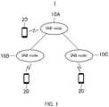
- FIG. 1 illustrates an exemplary configuration of a radio communication system according to an embodiment.
- Radio communication system 1 includes a plurality of IAB nodes 10A to 10C, and UEs 20 as an example of user terminals.
- IAB nodes 10A to 10C may be used for describing elements of the same kind while distinguishing them from each other, and only common numbers of the reference signs, as in " IAB nodes 10,” may be used for describing elements of the same kind without distinguishing them from each other in the below-mentioned embodiment.
- IAB nodes 10A to 10C are an example of radio nodes, and are connected to other IAB nodes 10 by radio communication.
- IAB node 10B and IAB node 10C are connected to IAB node 10A.
- IAB node 10A may be called “first IAB node” and IAB nodes 10B, 10C may be called “second IAB node”.
- IAB nodes 10A to 10C each form a cell as a radio communicable area. That is, IAB node 10 has a function of a base station. UE 20 in the cell can be radio-connected to IAB node 10 forming the cell.
- IAB node 10A may be connected to a core network (CN).
- IAB node 10A may be called an IAB donor.
- the number of IAB nodes 10 is three and the number of UEs 20 is three, but the number of IAB nodes 10 and the number of UEs 20 included in radio communication system 1 may be set to any number.
- FIG. 2 illustrates an exemplary configuration of IAB node 10.
- IAB node 10 includes control section 100, storage section 102, for-UE radio communication section 103, and for-BH (backhaul) radio communication section 104.
- For-UE radio communication section 103 executes processing of radio communication to UE 20.
- For-BH radio communication section 104 executes processing of radio communication to other IAB nodes 10. That is, for-BH radio communication section 104 executes processing of radio backhaul communication.
- Control section 100 controls radio communication of for-UE radio communication section 103.
- control section 100 controls radio communication of for-BH radio communication section 104. It should be noted that an operation of after-described IAB node 10 may be realized by the control of control section 100.
- Storage section 102 stores therein various pieces of information that are used in the operation of control section 100.
- Second IAB node 10 detects an SSB transmitted from first IAB node 10 and is connected to first IAB node 10, for example.
- SSB is an abbreviation of SS/PBCH Block.
- SS is an abbreviation of Synchronization Signal.
- PBCH is an abbreviation of Physical Broadcast Channel.
- the SSB to be used for connection of second IAB node 10 to first IAB node 10 may be at least one of next (A1) or (A2).
- UE 20 based on Release (Rel)-15 searches a predetermined frequency at the initial access to detect the SSB.
- the frequency that is searched by UE 20 at the initial access in this way is called sync-raster.
- the SSB to be arranged on the sync-raster is called a sync-raster SSB.
- the frequency that is not searched by UE 20 based on Rel-15 at the initial access is called off sync-raster.
- the SSB to be arranged on the off sync-raster is called an off sync-raster SSB.
- UE 20 based on Rel-15 does not search for the off sync-raster SSB without instructions from the base station, at the time including the initial access time. Therefore, with respect to the off sync-raster SSB, a mapping pattern of SSB in a periodicity and/or in a time domain not supported by Rel-15 can be studied for IAB node 10.
- constraints of next (B1) and (B2) with respect to the SSB are present in Rel-15.
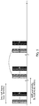
- SSBs to which the same beam forming is applied are expressed in the same hatching.
- the expression by the hatching is made in the same way in FIG. 4 , FIG. 5 and FIG. 6 .
- 64 pieces of SSBs at the maximum can be arranged in the half frame (5 ms).
- a group of the SSBs in the half frame is transmitted in a predetermined SSB periodicity.
- the SSB periodicity is any of 5 ms, 10 ms, 20 ms, 40 ms, 80 ms and 160 ms.
- Rel-15 for example, as illustrated in FIG.
- UE 20 assumes SSB #n (n is the integral number of 1 to N) in the first half frame and SSB #n in the second half frame as the same beam forming. It should be noted that "SSB #n" indicates an SSB of an SSB index n.
- IAB node 10 that satisfies at least one of the above (C1) to (C3) and the radio communication method will be described. That is, IAB node 10 and the radio communication method according to the present embodiment satisfy at least one of (D1) to (D3) hereinafter.
- IAB node 10 and the radio communication method according to the present embodiment support at least one of method 1, method 2, method 3 and method 4, which will be described later, with respect to the off sync-raster SSB for satisfying at least one of the above (D1) to (D3).
- First IAB node 10 notifies or broadcasts whether to assume the QCL with respect to the SSBs to which the same SSB index is applied, in the half frames (5 ms) different from each other. Whether to assume the QCL may be implicitly notified or broadcasted, or may be explicitly notified or broadcasted.
- Example 1A, Example 1B and Example 1C with respect to method 1 will be described.
- second IAB node 10 In a case where the transmission of the SSBs more than 64 pieces is notified by a bitmap in which ssb-PositionsInBurst parameters are expanded, in the configuration of a serving cell or IAB node 10, such as servingCellConfigCommon parameters, second IAB node 10 operates as follows. Alternatively, in the configuration where the SSB index starts from "0", in a case where the transmission of the SSBs equal to or after the SSB index "64" is notified, second IAB node 10 operates as follows. That is, second IAB node 10 assumes that the SSB is transmitted in each of both the half frames (5 ms) in one radio frame (10 ms). Second IAB node 10 does not assume the QCL in SBBs to which the same SSB index is applied and transmitted in each of the half frames different from each other.
- first IAB node 10 may explicitly instruct whether to assume the QCL in SBBs to which the same SSB index is applied and transmitted in each of the half frames different from each other to second IAB node 10 by one independent bit.
- the instruction may be made in such a manner that in a case where the one bit is "1", the QCL is not assumed and in a case where the one bit is "0", the QCL is assumed.
- the instruction may be made in such a manner that in a case where the one bit is "1”, the QCL is assumed and in a case where the one bit is "0", the QCL is not assumed.
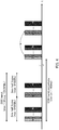
- Example 1A will be described with reference to FIG. 4 .
- First IAB node 10 locates the SSB in each of the former and latter (that is, both) half frames (5 ms) in one radio frame (10 ms), for example.
- the maximum number of the SSBs that can be arranged in each half frame may be 64 pieces.
- first IAB node 10 can transmit the 128 pieces of the SSBs at the maximum in an SSB burst corresponding to one radio frame in FIG. 4 .
- Second IAB node 10 does not assume the QCL between SSB #n of the former half frame and SSB #n of the latter half frame in a case where the SSBs more than 64 pieces are detected in the SSB burst.
- second IAB node 10 does not assume the QCL between SSB #n of the former half frame and SSB #n of the latter half frame in a case where the transmission of the SSB of SSB #64 and after that is detected in the SSB burst. Therefore, the beam forming different from each other can be applied to each of the SSBs in the SSB burst. That is, first and second IAB nodes 10 can use the beam patterns more than 64 pieces.
- the periodicity of the SSB burst may be configured to be longer than 160 ms. By the configuration, the power consumption of IAB node 10 can be suppressed.
- First IAB node 10 uses bits in the PBCH of the off sync-raster SSB and notifies whether to apply the bean forming different from each other in the SSB in each of the former and latter (that is, both) half frames (5 ms) in the one radio frame (10 ms).
- the bit in the PBCH used in this notification may be a bit of a ssb-subcarrier Offset (that is, k_SSB) parameter or a pdcch-ConfigSIBI parameter. That is, in a case of the off sync-raster SSB, a bit of a predetermined parameter in the PBCH may be used for an object different from a case of the sync-raster SSB.
- second IAB node 10 is located in time positions different form each other in the measurement window and does not assume the QCL to the SSBs to which the same SSB index is applied.
- SMTC is an abbreviation of SSB based RRM measurement timing configuration.
- RRM is an abbreviation of Radio Resource Management.
- first IAB node 10 may explicitly instruct whether to assume the QCL in the SBBs to which the same SSB index is applied, to second IAB node 10 by one independent bit.
- second IAB node 10 may not assume the QCL in the SBBs to which the same SSB index is applied in a case where the transmission of the SSBs more than 64 pieces is notified by the bitmap indicating the SSB index of a measurement target. Or second IAB node 10 may not assume the QCL in the SBBs to which the same SSB index is applied in a case where the transmission of the SSBs equal to or after the SSB index "64" is notified in the configuration where the SSB index starts from "0".
- the period longer than 5 ms of the longest supported by Rel-15 is supported.
- the periodicity longer than 160 ms of the longest supported by Rel-15 is supported. For example, in method 2, at least one of next Example 2A and Example 2B is supported.
- a period for example, an SMTC parameter
- a period longer than 5 ms is supported.
- the periodicity for example, periodicityAndOffset parameter
- a parameter of a transmission pattern of SSB for example, an ssb-PositionsInBurst parameter
- a ServingCell ConfigCommon parameter the instruction by the bitmap having the bit number more than 64 pieces is supported.
- the periodicity longer than 160 ms is supported.
- first IAB node 10 may include at least any of the configuration for the measurement and the configuration for SSB transmission of the serving cell to broadcast information (for example, SIB) for transmission.
- the broadcast information can be used as information for IAB node in the periphery to perform detection and measurement.
- second IAB node 10 may perform the detection or measurement of first IAB node 10 by using the broadcast information.
- SIB System Information Block
- a broad band measurement of 20 PRB or more width (that is, equal to or more than a predetermined frequency bandwidth) is supported. Measurement precision in one time of measurement can be enhanced by supporting the broad band measurement.
- PRB is an abbreviation of Physical Resource Block.
- Method 3 at least one of next Example 3A and Example 3B is supported.
- second IAB node 10 assumes the QCL with respect to CSI-RS of the same symbol as that of the SSB and uses SSB RE and CSI-RS RE to derive RSRP or SINR for RRM, RLM or BFD, for example.
- RE is an abbreviation of Resource Element.
- RSRP is an abbreviation of Reference Signal Received Power.
- SINR is an abbreviation of Signal-to-Interference plus Noise power Ratio.
- BFD is an abbreviation of Beam Failure Detection.
- second IAB node 10 In the off sync-raster, the SSB is repeatedly arranged in the frequency direction, and in a case where it is explicitly instructed to support the broad band measurement equal to or more than 20 PRB width in the configuration for measurement, in the configuration of the serving cell or in the PBCH, second IAB node 10 is operated as follows. That is, second IAB node 10 uses RE of the SSBs repeatedly arranged in the frequency direction to derive the RSRP or SINR
- the repeat number of the SSB in the off sync-raster as described above may be defined by one only (for example, the repeat number is "3") depending upon a specification. Or, candidates of a plurality of the repeat numbers (for example, the candidates "3", "5" of the repeat numbers) are defined depending upon a specification, and one of the candidates may be explicitly instructed.
- the SSB sample number less than the SSB sample number defined in Rel-15 may be assumed in the requirement of measurement delay.
- the sample number of five is assumed for Intra-band RRM (for example, refer to Rel-15 TS38.133 Section 9.2.5.2).
- the sample number less than the sample number of five may be assumed.
- First IAB node 10 changes the beam for each periodicity of an SSB burst periodicity and/or an SMTC periodicity for transmission, and notifies or broadcasts whether to assume the QCL in the SSBs to which the same SSB index is applied. Whether to assume the QCL may be implicitly or explicitly notified or broadcasted. For example, first IAB node 10 transmits SSB to which the beam forming #0 to #63 is applied for each even-numbered periodicity and transmits SSB to which the beam forming #64 to #127 is applied for each odd-numbered periodicity.
- Example 4A, Example 4B and Example 4C will be described with respect to method 4.
- second IAB node 10 In a case where the transmission of the SSBs more than 64 pieces is notified by the bitmap in which the ssb-PositionsInBurst parameter is expanded in the configuration of the serving cell or IAB node 10, such as the servingCellConfigCommon parameter (in a case of being implicitly notified), second IAB node 10 is operated as follows. That is, second IAB node 10 assumes that the beam forming changes for each periodicity and does not assume the QCL in the SSBs to which the same SSB index is applied.
- second IAB node 10 assumes that the beam forming changes for each periodicity in a case where the transmission of SSB equal to or after SSB index "64" is notified in the configuration where the SSB index starts from "0" and may not assume the QCL in the SSBs to which the same SSB index is applied.
- second IAB node 10 In the configuration where the transmission of the SSBs more than 64 pieces is notified by the bitmap or in the configuration where the SSB index starts from "0", in a case where the transmission of SSB after the SSB index "64" is notified and the instruction indicating that the beam forming changes for each periodicity is notified (that is, in a case of being explicitly notified), second IAB node 10 is operated as follows. That is, second IAB node 10 assumes that the beam forming changes for each periodicity and does not assume the QCL in the SSBs to which the same SSB index is applied.
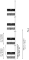
- FIG. 5 differs in a point where the half frames including SSBs are not continuous from FIG. 4 .
- First IAB node 10 transmits SSBs of 64 pieces at the maximum in each of the first and second half frames including SSBs in the SSB burst.
- First IAB node 10 notifies the SSB transmission in the SSB burst by the bitmap.
- Second IAB node 10 does not assume the QCL between SSB #n of the first half frame and SSB #n of the second half frame, for example, in a case where the transmission of SSBs more than 64 pieces is notified by the bitmap.
- first IAB node 10 may notify a period between the first half frame and the second half frame as SSB burst periodicity.
- second IAB node 10 determines not to assume the QCL by the bitmap, twice the SSB burst periodicity notified from first IAB node 10 may be assumed as a period of the SSB burst.
- First IAB node 10 uses the bit in the PBCH of the off sync-raster SSB to notify whether or not the QCL assumption changes for each periodicity.
- the bit in the PBCH used in this notification may be a bit of the ssb-subcarrierOffset (that is, k_SSB) parameter or pdcch-ConfigSIBI parameter, for example.
- second IAB node 10 In a case where the transmission of the SSBs in the measurement target SSB index more than 64 pieces is notified by the bitmap in the configuration for measurement, such as the MeasObjectNR parameter or in a case where the measurement of SSBs equal to or after the SSB index "64" is notified (in a case of being implicitly notified) in the configuration where the measurement target SSB index starts from "0", second IAB node 10 is operated as follows. That is, second IAB node 10 assumes that the beam changes for each periodicity and does not assume the QCL in the SSBs to which the same SSB index is applied.
- second IAB node 10 In the configuration where the transmission of SSBs of the measurement target SSB index more than 64 pieces is notified by the bitmap or in the configuration where the measurement target SSB index starts from "0", in a case where the measurement of SSBs equal to or after the SSB index "64" is notified and the instruction indicating that the beam forming changes for each periodicity is notified (that is, in a case of being explicitly notified), second IAB node 10 is operated as follows. That is, second IAB node 10 assumes that the beam forming changes for each periodicity and does not assume the QCL in the SSBs to which the same SSB index is applied.
- IAB node 10 may notify sweeping in the SSB beam more than 64 pieces of UE 20 based on Rel-16, for example.
- rate matching at the receiving of PDSCH Physical Downlink Shared Channel
- an RRM measurement operation may be performed to SSBs more than 64 pieces as a target.
- IAB node 10 is required to cause UE 20 based on Rel-15 to perform only measurement to the SSB beam of 64 pieces as the maximum beam forming number.
- IAB node 10 may cause UE 20 based on Rel-15 to perform measurement of SSB beams to 64 pieces based on a first measurement instruction, and may cause UE 20 based on Rel-15 to perform measurement of the remaining SSB beams based on a second measurement instruction.
- the periodicity (SSB group periodicity) of the half frame (5 ms) including the SSB and the SSB burst periodicity in the SSB burst may be independently configured.
- first IAB node 10 may notify or broadcast the SSB group periodicity and the SSB burst periodicity individually to UE 20.
- First IAB node 10 transmits SSBs of 64 pieces at the maximum in each of the first and second half frames including SSBs, in the SSB burst, for example.
- a period between the first half frame and the second half frame corresponds to the SSB group periodicity.
- a period between the first SSB burst and the second SSB burst corresponds to the SSB burst periodicity.
- the SSB group periodicity may be selected out of candidates in advance defined, such as 5 ms, 10 ms, 20 ms and 40 ms.
- the SSB burst periodicity may be periodicity longer than 160 ms.
- FIG. 4 can be said as an example where the SSB group periodicity is fixed to 5 ms
- FIG. 5 can be said as an example where the SSB group periodicity is fixed to 1/2 times the SSB burst periodicity.
- the SSB group periodicity and the SSB burst periodicity are not limited to fixation, and may be variable.
- the maximum number of SSBs included in the half frame is not limited to 64 pieces, but may be more than or less than 64 pieces. In the present embodiment, the maximum number of SSBs included in the SSB burst is not limited to 128 pieces, but may be more than or less than 128 pieces. The number of the half frames including SSBs included in the SSB burst may be more than two.
- the maximum number of SSBs included in the SSB burst may differ for each periodicity of the SSB burst.
- IAB node 10 may switch the maximum numbers "128 pieces” and "256 pieces" of SSBs included in the SSB burst for each periodicity of the SSB burst in accordance with a communication environment, for example. Therefore, it is possible to control the tradeoff between extension of the SSB burst periodicity and an improvement of flexibility of the SSB beam following an increase in the maximum number of the SSBs.
- the SSBs can be arranged more flexibly than the sync-raster in the off sync-raster.
- the beam forming of the patterns more than the sync-raster can be applied to the SSBs in the off sync-raster.
- first IAB node 10 can apply the beam reaching more sharply and farther than the sync-raster to the SSB in the off sync-raster.
- first IAB node 10 can apply the beam more appropriate in the direction of second IAB node 10 than the sync-raster to the SSB in the off sync-raster.
- first IAB node 10 can transmit the SSB burst in the periodicity longer than the sync-raster in the off sync-raster.
- First IAB node 10 can use the bandwidth (many PRB number) broader than the sync-raster to the transmission of the SSB in the off sync-raster. That is, second IAB node 10 can measure the SSB in the bandwidth broader than the sync-raster in the off sync-raster.
- each of the functional blocks may be realized by using one apparatus in which the functional blocks are connected physically or logically or may be realized by a plurality of apparatuses configured by directly or indirectly (for example, wiredly or radio) connecting two or more of apparatuses separated physically or logically.
- the functional blocks may be realized by combining software to the one apparatus or the plurality of apparatuses.
- the function includes judging, deciding, determining, computing, calculating, processing, deriving, investigating, searching, confirming, receiving, transmitting, outputting, accessing, resolving, choosing, selecting, establishing, comparing, assuming, expecting, regarding, broadcasting, notifying, communicating, forwarding, configuring, reconfiguring, allocating, mapping, and assigning, but is not limited thereto.
- the functional block (configuring section) functioning the transmission is called a transmission section or a transmitter.
- the realizing method of any of them, as described above, is also not limited particularly.
- the IAB node, the user terminal and the like according to an embodiment in the present disclosure may function as a computer configured to perform the processing of the radio communication method of the present disclosure.
- FIG. 7 illustrates an example of the hardware configuration of the IAB node and the user terminal according to the embodiment in the present disclosure.
- IAB node 10 and user terminal 20 described above may be configured as a computer apparatus to physically include processor 1001, memory 1002, storage 1003, communication apparatus 1004, input apparatus 1005, output apparatus 1006, and bus 1007.
- IAB node 10 and user terminal 20 may be configured to include one apparatus or a plurality of the apparatuses illustrated in the figures or may be configured without including part of the apparatuses.
- IAB node 10 and user terminal 20 can be realized by causing hardware of processor 1001, memory 1002 or the like to read in specified software (program) to operate processor 1001, and control communication by communication apparatus 1004, or control at least one of readout and writing of data in memory 1002 and storage 1003.
- Processor 1001 causes, for example, an operating system to operate and control an entire computer.
- Processor 1001 may be configured by an interface with the peripheral equipment, a control apparatus, an operational apparatus, and a Central Processing Unit (CPU) including a register.
- control section 100 and the like described above may be realized by processor 1001.
- Processor 1001 reads out programs (program codes), a software module, data and the like to memory 1002 from at least one of storage 1003 and communication apparatus 1004 and executes various kinds of processing according to them.
- the program causes the computer to perform at least part of the operation described in the embodiment.
- control section 100 of IAB node 10 may be stored in memory 1002, and may be realized by a control program operated in processor 1001, and the other functional blocks also may be realized in the similar manner.
- the effect that the various kinds of processing are executed by single processor 1001 is described, but they may be executed by two or more of processors 1001 simultaneously or sequentially.
- Processor 1001 may be implemented by one or more of chips.
- the program may be transmitted through an electrical communication line from a network.
- Memory 1002 is a computer readable record medium, and for example, may be configured by at least one of a ROM (Read Only Memory), an EPROM (Erasable Programmable ROM), an EEPROM (Electrically Erasable Programmable ROM), a RAM (Random Access Memory) and the like.
- Memory 1002 may be called a register, a cache, a main memory (main memory apparatus) or the like.
- Memory 1002 can store therein executable programs (program codes), software modules and the like for executing the radio communication method according to the embodiment of the present disclosure.
- Storage 1003 is a computer readable record medium, and may be configured by at least one of an optical disc such as a CD-ROM (Compact Disc ROM), a hard disc drive, a flexible disc, an optical magnetic disc (for example, a compact disc, a digital versatile disc, a Blu-ray (registered trademark) disc), a smart card, a flash memory (for example, a card, a stick, or a key drive), a floppy (registered trademark) disc, a magnetic strip and the like.
- Storage 1003 may be called an auxiliary memory apparatus.
- the memory medium may be, for example, a data base including at least one of memory 1002 and storage 1003, a server and another appropriate medium.
- Communication apparatus 1004 is a hardware (transmission/reception device) for communication between computers through at least one of a wired network and a radio network, and, for example, is called a network device, a network controller, a network card, a communication module or the like.
- Communication apparatus 1004 may be configured to include a high-frequency switch, a duplexer, a filter, and a frequency synthesizer for realizing at least one of, for example, Frequency Division Duplex (FDD) and Time Division Duplex (TDD).
- FDD Frequency Division Duplex
- TDD Time Division Duplex
- antennas and the like of the base station and the terminal may be realized by communication apparatus 1004.
- a transmission/reception section may be mounted to be physically or logically separated by a transmission section and a reception section.
- Input apparatus 1005 is an input device (for example, a keyboard, a mouth, a microphone, a switch, a button, a sensor or the like) receiving input from an outside.
- Output apparatus 1006 is an output device (for example, a display, a speaker, an LED lamp or the like) performing output to an outside.
- Input apparatus 1005 and output apparatus 1006 may be configured to be united (for example, a touch panel).
- Bus 1007 may be configured using a single bus or may be configured using buses different between apparatuses.
- Base station 10 and user terminal 20 may be configured to include hardware such as a microprocessor, a digital signal processor (DSP), an application specific integrated circuit (ASIC), a programmable logic device (PLD), a field programmable gate array (FPGA), and part or all of the respective functional blocks may be realized by the hardware.
- DSP digital signal processor
- ASIC application specific integrated circuit
- PLD programmable logic device
- FPGA field programmable gate array
- processor 1001 may be implemented using at least one of the hardware.
- Notification of Information is not limited to the aspects and embodiments described in the present disclosure, and may be executed by using other methods.
- the notification of information may be executed by physical layer signaling (for example, DCI (Downlink Control Information), UCI (Uplink Control Information)), higher layer signaling (for example, RRC (Radio Resource Control) signaling, MAC (Medium Access Control) signaling, broadcast information, (MIB (Master Information Block), SIB (System Information Block)) or other signals, or a combination thereof.
- the RRC signaling may be called an RRC message, and, for example, may be an RRC connection setup message, an RRC connection reconfiguration message or the like.
- LTE Long Term Evolution
- LTE-A Long Term Evolution-Advanced
- SUPER 3G IMT-Advanced
- 4G 4 th generation mobile communication system
- 5G 5 th generation mobile communication system
- FRA Full Radio
- WCDMA registered trademark
- GSM registered trademark
- CDMA 2000 Code Division Multiple Access 2000
- UMB Universal Mobile Broadband
- IEEE 802. 11 Wi-Fi (registered trademark)
- IEEE 802. 16 WiMAX (registered trademark)
- UWB Ultra-Wideband
- Bluetooth registered trade mark
- a system using another appropriate system and a next generation system expanded based thereupon.
- the aspects and embodiment may be applied to a combination of a plurality of systems (for example, a combination of at least one of LTE and LTE-A, and 5G, or the like).
- the particular operation configured to be performed in the base station in the present disclosure may be performed in the upper node depending upon the condition.
- various operations performed for communication with the terminal can be apparently performed by at least one of the base station and the other network node (for example, MME, S-GW or the like can be conceived, but not limited thereto).
- MME Mobility Management Entity
- S-GW Serving GPRS Support Node
- Information and the like can be outputted from an upper layer (or a lower layer) to a lower layer (or an upper layer).
- the information and the like may be inputted and outputted through a plurality of network nodes.
- the information and the like inputted / outputted may be stored in a particular place (for example, a memory), and may be managed using a management table.
- the information and the like to be inputted / outputted can be overwritten, updated or appended.
- the outputted information and the like may be deleted.
- the inputted information and the like may be transmitted to the other apparatus.
- the determination may be performed by a value (0 or 1) expressed by one bit, may be performed by a true/false value (Boolean: true or false) or may be performed by a comparison of a numerical value (for example, comparison with a predetermined value).
- the notification of the predetermined information (for example, notification of "being X") is not limited to one being explicitly notified, but may be implicitly executed (for example, by not executing the notification of the predetermined information).
- the present disclosure is in detail described, but it is apparent for those skilled in the art that the present disclosure is not limited to the embodiment described in the present disclosure.
- the present disclosure can be executed as a modification aspect and a variation aspect without departing from the spirit and the scope of the present disclosure defined in the description of the appended claims. Accordingly, the description of the present disclosure aims at an exemplary explanation, and does not have any limiting meaning to the present disclosure.
- Software should be interpreted to be as broad as to mean a command, a command set, a code, a code segment, a program code, a program, a subprogram, a software module, an application, a software application, a software package, a routine, a subroutine, an object, an executable file, an execution sled, a procedure, a function and the like regardless of whether the software is called software, firmware, middleware, microcode or a hardware description language, or called the other name.
- the software, command, information and the like may be transmitted/received through a transmission medium.
- a transmission medium for example, in a case where the software is transmitted from a website, a server or the other remote source by using at least one of wired technologies (a coaxial cable, an optical fiber cable, a twist pair, a digital subscriber line (DSL) and the like) and radio technologies (an infrared beam, a microwave and the like), at least one of the wired technologies and the radio technologies is encompassed in the definition of the transmission medium.
- wired technologies a coaxial cable, an optical fiber cable, a twist pair, a digital subscriber line (DSL) and the like
- radio technologies an infrared beam, a microwave and the like
- the information, the signal and the like described in the present disclosure may be expressed by using any of various different technologies.
- data, orders, commands, information, signals, bits, symbols, chips, and the like that can be referred to over the entire description may be expressed by voltages, electrical current, electromagnetic waves, magnetic fields or magnetic particles, optical fields or photons, or any combination thereof.
- the terms described in the present disclosure and the terms necessary for the understanding of the present disclosure may be replaced with terms having the same meaning or the meaning similar thereto.
- at least one of the channel and the symbol may be a signal (may be signaling).
- the signal may be a message.
- the component carrier (CC) may be called a carrier frequency, a cell, a frequency carrier, and the like.
- system and “network” used in the present disclosure are interchangeably used.
- the information, the parameter and the like described in the present disclosure may be expressed by using an absolute value, may be expressed by using an absolute value from a predetermined value, or may be expressed by using different information corresponding thereto.
- the radio resource may be instructed by the index.
- the names used in the parameters are not limited names in any respect. Further, numerical expressions and the like using the parameters may be different from those explicitly disclosed in the present disclosure in some cases.
- the various channels (for example, PUCCH, PDCCH and the like) and the information elements can be identified by every proper name, and therefore, the various names allotted to the various channels and information elements are not limited names in any respect.
- base station radio base station
- radio base station fixed station
- NodeB nodeB
- eNodeB eNodeB
- gNodeB gNodeB
- the base station can accommodate one cell or a plurality (for example, three) of cells.
- an entire coverage area of the base station can be sectioned into a plurality of smaller areas, and each of the smaller areas can provide communication services by a base station subsystem (for example, a compact base station (RRH "Remote Radio Head") for indoors).
- a base station subsystem for example, a compact base station (RRH "Remote Radio Head" for indoors).
- RRH Remote Radio Head
- MS mobile station
- UE user equipment
- terminal terminal
- the mobile station may be called a subscriber station, a mobile unit, a subscriber unit, a wireless unit, a remote unit, a mobile device, a wireless device, a wireless communication device, a remote device, a mobile subscriber station, an access terminal, a mobile terminal, a wireless terminal, a remote terminal, a handset, a user agent, a mobile client, a client, or some other appropriate terms by those skilled in the art in some cases.
- At least one of the base station and the mobile station may be called a transmission apparatus, a reception apparatus, a communication apparatus, and the like. It should be noted that at least one of the base station and the mobile station may be a device mounted on a mobile body, a mobile body itself or the like.
- the mobile body may be a vehicle (for example, a car, an airplane or the like), an unmanned mobile body (for example, drone, automated driving car, or the like), or a robot (manned or unmanned type).
- At least one of the base station and the mobile station includes an apparatus that does not necessarily move at the communication operation.
- at least one of the base station and the mobile station may be an I o T (Internet of things) device such as a sensor.
- the base station in the present disclosure may be replaced with the user terminal.
- the communication between the base station and the user terminal is replaced with the communication between a plurality of user terminals (for example, may be called D2D (Device to Device), V2X (Vehicle-to-Everything) or the like)
- each of the aspects and embodiments in the present disclosure may be applied.
- the function of base station 10 may be made to the configuration of user terminal 20.
- terms of "uplink” and "downlink” may be replaced with terms corresponding to terminal-to-terminal communication (for example, "side").
- an uplink channel, a downlink channel or the like may be replaced with a side channel.
- the user terminal in the present disclosure may be replaced with the base station.
- the function of user terminal 20 may be regarded as the configuration of base station 10.
- determining and “deciding” used in the present disclosure possibly include various operations in some cases.
- Determining” or “deciding” can include, for example, that, “judging", “calculating”, “computing”, “processing”, “deriving”, “investigating”, “looking up, searching or inquiring” (for example, in a table, a data base or in another data structure) or ascertaining is regarded as “determining” or “deciding”.
- determining and “deciding” can include that receiving (for example, receiving information), transmitting (for example, transmitting information), inputting, outputting or accessing (for example, accessing data in the memory) is regarded as “determining” or "deciding”.
- determining and “deciding” can include that resolving, selecting, choosing, establishing, comparing, or the like is regarded as “determining” or “deciding”. That is, “determining” and “deciding” can include that any operation is regarded as “determining” or “deciding”. In addition, “determining (deciding)” may be replaced with “assuming”, “expecting”, “considering” or the like.
- connection means every direct or indirect connection or coupling between two or more of elements, and can include that one or more of intermediate elements are present between two elements connected or coupled to each other.
- the coupling or the connection between the elements may be physical, logical or a combination thereof.
- connecting may be replaced with "accessing”.
- the two elements can be regarded to be "connected” or “coupled” to each other by using at least one of one or more of electrical wires, a cable and a printed electrical connection, and by using electromagnetic energy having wavelengths in a radio frequency domain, in a microwave domain and in an optical (both of visible and invisible) domain as some non-limiting and non-inclusive examples, and the like.
- the reference signal can also be abbreviated as RS (reference signal), and may be called a pilot according to the applied standard.
- any reference to elements using designations such as "first” and “second” used in the present disclosure the amount or the order of the elements is not limited as a whole.
- the calls can be used in the present disclosure as a convenient method making distinction between two or more of elements. Accordingly, the reference to the first and second elements does not mean that only two elements are adopted or that the first element must be prior to the second element in any form.
- the radio frame may be configured by one frame or a plurality of frames in a time domain.
- One frame or each of a plurality of frames may be called a subframe in a time domain.
- the subframe may be further configured by one slot or a plurality of slots in a time domain.
- the subframe may be a fixed time length (for example, 1 ms) that does not depend upon numerology.
- the numerology may be a communication parameter applicable to at least one of transmission and reception of some signal or channel.
- the numerology may indicate at least one of, for example, subcarrier spacing (SCS), a bandwidth, a symbol length, a cyclic prefix length, a transmission time interval (TTI), the symbol number per TTI, a radio frame configuration, specific filtering processing executed in a frequency domain by the transmission/reception device, specific windowing processing executed in a time domain by the transmission/reception device, and the like.
- SCS subcarrier spacing
- TTI transmission time interval
- the slot may be configured by one symbol or a plurality of symbols (OFDM (Orthogonal Frequency Division Multiplexing) symbol, SC-FDMA (Single Carrier Frequency Division Multiple Access) symbol and the like) in a time domain.
- the slot may indicate a time unit based on numerology.
- the slot may include a plurality of mini-slots.
- Each of the mini-slots may be configured by one symbol or a plurality of symbols in a time domain.
- the mini-slot may be called a sub-slot.
- the mini-slot may be configured by the smaller number of the symbols than the slot.
- PDSCH (or PUSCH) transmitted in a time unit larger than the mini-slot may be called a PDSCH (or PUSCH) mapping type A.
- PDSCH (or PUSCH) transmitted using the mini-slot may be called a PDSCH (or PUSCH) mapping type B.
- the radio frame, the subframe, the slot, the mini-slot and the symbol each represent a time unit at the time of transmitting signals.
- the radio frame, the subframe, the slot, the mini-slot and the symbol each may have a different call corresponding to each.
- one subframe may be called a transmission time interval (TTI), and a plurality of successive subframes may be called TTI, and one slot or one mini-slot may be called TTI. That is, at least one of the subframe and TTI may be a subframe (1 ms) in the existing LTE, may have a period (for example, 1 to 13 symbols) shorter than 1 ms or may have a period longer than 1 ms. It should be noted that a unit representing TTI may be called not the subframe, but the slot, the mini-slot or the like.
- TTI means, for example, the minimum time unit of scheduling in the radio communication.
- the base station performs scheduling of allotting the radio resource (frequency bandwidth and transmission power that can be used in each user terminal) to each user terminal in a TTI unit. It should be noted that the definition of TTI is not limited thereto.
- the TTI may be a transmission time unit such as a data packet (transport block), a code block and a codeword, subjected to channel coding or a processing unit such as scheduling and link adaptation.
- a time division for example, the symbol number
- the transport block, the code block, the codeword and the like may be shorter than the TTI.
- one or more of the TTIs may be a minimum time unit of the scheduling.
- the slot number (mini-slot number) configuring the minimum time unit of the scheduling may be controlled.
- the TTI having a time length of 1 ms may be called a regular TTI (TTI in LTE Rel. 8-12), a normal TTI, a long TTI, a regular subframe, a normal subframe, a long subframe, a slot, and the like.
- the TTI shorter than the regular TTI may be called a shortened TTI, a short TTI, a partial TTI (partial or fractional TTI), a shortened subframe, a short subframe, a mini-slot, a sub-slot, a slot, and the like.
- the long TTI (for example, the regular TTI, the subframe, or the like) may be replaced with a TTI having a time length exceeding 1 ms
- the short TTI (for example, the shortened TTI or the like) may be replaced with a TTI having a TTI length of less than the TTI length of the long TTI and equal to or more than 1 ms.
- a resource block is a resource allocation unit in the time domain and the frequency domain, and the resource block may include one subcarrier or a plurality of continuous subcarriers in the frequency domain.
- the number of the subcarriers included in the RB may be the same number regardless of the numerology, such as 12.
- the number of the subcarriers included in the RB may be determined based on the numerology.
- the time domain of the RB may include one symbol or a plurality of symbols, and may have a length of one slot, one mini-slot, one subframe, or one TTI.
- One TTI, one subframe and the like each may be constituted by one resource block or a plurality of resource blocks.
- one RB or a plurality of RBs may be called a physical resource block (PRB: Physical RB), a subcarrier group (SCG), a resource element group (REG), a PRB pair, an RB pair, and the like.
- PRB Physical resource block
- SCG subcarrier group
- REG resource element group
- PRB pair an RB pair, and the like.
- the resource block may be constituted by one resource element or a plurality of resource elements (RE: Resource Element).
- RE Resource Element
- one RE may be a radio resource domain of one subcarrier and one symbol.
- a bandwidth part (may be called a partial bandwidth or the like) may indicate a subset of continuous common RBs (common resource blocks) for numerology in some carrier.
- the common RB may be specified by an index of the RB as a reference of a common reference point of the carrier.
- the PRB may be defined by some BWP and may be numbered in the BWP.
- the BWP may encompass a BWP for UL (UL BWP) and a BWP for DL (DL BWP).
- UL BWP UL BWP
- DL BWP DL BWP
- one BWP or a plurality of BWPs may be configured in one carrier.
- At least one of the configured BWPs may be active, and the UE may not assume to transmit/receive a predetermined signal/channel outside of the active BWP. It should be noted that “cell”, “carrier” and the like in the present disclosure may be replaced with “BWP”.
- Each structure of the radio frame, the subframe, the slot, the mini-slot, the symbol and the like is illustrative only.
- each configuration of the number of subframes included in the radio frame, the number of slots per the subframe or the radio frame, the number of mini-slots included in the slot, the numbers of symbols and RBs included in the slot or the mini-slot, the number of subcarriers included in the RB, the number of symbols in the TTI, a symbol length, a cyclic prefix (CP) length, and the like can be changed in various ways.
- Maximum transmission power in the description of the present disclosure may mean a maximum value of transmission power, may mean nominal UE maximum transmission power, and rated UE maximum transmission power.
- the sentence of "A and B differ” may mean a sentence of "A and B differ from each other”.
- the sentence also may mean a sentence of "A and B each differ from C”.
- Terms of "separated”, “coupled” and the like also may be interpreted as similar to "differ”.
- An aspect of the present disclosure is useful for a radio communication system.
Landscapes
- Engineering & Computer Science (AREA)
- Signal Processing (AREA)
- Computer Networks & Wireless Communication (AREA)
- Mobile Radio Communication Systems (AREA)
Abstract
Description
- The present disclosure relates to a radio node and a radio communication method.
- Long Term Evolution (LTE) has been specified for achieving a higher data rate, lower latency, and the like in a Universal Mobile Telecommunications System (UMTS) network. Successor systems of the LTE have also been studied for achieving a broader bandwidth and a higher speed based on the LTE. Examples of successor systems of the LTE include the systems called LTE-Advanced (LTE-A), Future Radio Access (FRA), 5th generation mobile communication system (5G), 5G plus (5G+), Radio Access Technology (New-RAT), and New Radio (NR).
- Technologies of Integrated Access and Backhaul (IAB) integrating an access link and a backhaul link have been studied for the future radio communication system (for example, 5G) (NPL 1). In the IAB, a radio node such as an IAB node forms a user terminal (User Equipment (UE)) and a radio access link, and forms another IAB node and/or a radio base station, and a radio backhaul link.
-
- NPL 1
3GPP TR 22.804 V16.1.0, "Study on Communication for Automation Vertical Domains (Release 16)," September 2018 - NPL 2
3GPP TSG RAN Meeting #78 RP-172290, "Study on Integrated Access and Backhaul for NR," December 2017 - NPL 3
3GPP TSG RAN WGI Meeting #94b R1-1811256, "Enhancements to support NR backhaul links," October 2018 - However, studies on signal measurement or connection between the radio nodes such as the IAB nodes are insufficient and further studies have been demanded.
- An object of an aspect of the present disclosure is to provide a radio node and a radio communication method realizing more flexible signal measurement or connection between radio nodes.
- A radio node according to one aspect of the present disclosure includes: a reception section that periodically receives a plurality of signals including at least one of synchronization information and broadcast channel information; and a control section that determines whether to assume QCL (Quasi co-location) between the signal in a first period and the signal in a second period based on at least one of the synchronization information and the broadcast channel information.
- According to the present disclosure, more flexible signal measurement or connection between the radio nodes can be realized.
-
-
FIG. 1 illustrates an exemplary configuration of a radio communication system according to an aspect of the present disclosure; -
FIG. 2 illustrates an exemplary configuration of an IAB node according to the aspect of the present disclosure; -
FIG. 3 illustrates an exemplary Synchronization Signal Block (SSB) transmission of Release (Rel)-15 according to the aspect of the present disclosure; -
FIG. 4 illustrates a first example of the SSB transmission according to the aspect of the present disclosure; -
FIG. 5 illustrates a second example of the SSB transmission according to the aspect of the present disclosure; -
FIG. 6 illustrates a third example of the SSB transmission according to the aspect of the present disclosure; and -
FIG. 7 illustrates an example of a hardware configuration of the IAB node and a user terminal according to the aspect of the present disclosure. - Hereinafter, an embodiment according to an aspect of the present disclosure will be described with reference to the accompanying drawings.
-
FIG. 1 illustrates an exemplary configuration of a radio communication system according to an embodiment. -
Radio communication system 1 includes a plurality ofIAB nodes 10A to 10C, andUEs 20 as an example of user terminals. It should be noted that, reference signs, as in "IAB nodes 10A to 10C" may be used for describing elements of the same kind while distinguishing them from each other, and only common numbers of the reference signs, as in "IAB nodes 10," may be used for describing elements of the same kind without distinguishing them from each other in the below-mentioned embodiment. -
IAB nodes 10A to 10C are an example of radio nodes, and are connected toother IAB nodes 10 by radio communication. In a case ofFIG. 1 ,IAB node 10B andIAB node 10C are connected toIAB node 10A. Hereinafter, in somecases IAB node 10A may be called "first IAB node" andIAB nodes -
IAB nodes 10A to 10C each form a cell as a radio communicable area. That is, IABnode 10 has a function of a base station.UE 20 in the cell can be radio-connected toIAB node 10 forming the cell. - It should be noted that, although not illustrated in
FIG. 1 ,IAB node 10A may be connected to a core network (CN). In this case, IABnode 10A may be called an IAB donor. InFIG. 1 , the number ofIAB nodes 10 is three and the number ofUEs 20 is three, but the number ofIAB nodes 10 and the number ofUEs 20 included inradio communication system 1 may be set to any number. -
FIG. 2 illustrates an exemplary configuration ofIAB node 10. - As illustrated in
FIG. 2 ,IAB node 10 includescontrol section 100,storage section 102, for-UEradio communication section 103, and for-BH (backhaul)radio communication section 104. - For-UE
radio communication section 103 executes processing of radio communication to UE 20. - For-BH
radio communication section 104 executes processing of radio communication toother IAB nodes 10. That is, for-BHradio communication section 104 executes processing of radio backhaul communication. -
Control section 100 controls radio communication of for-UEradio communication section 103. In addition,control section 100 controls radio communication of for-BHradio communication section 104. It should be noted that an operation of after-describedIAB node 10 may be realized by the control ofcontrol section 100. -
Storage section 102 stores therein various pieces of information that are used in the operation ofcontrol section 100. -
Second IAB node 10 detects an SSB transmitted fromfirst IAB node 10 and is connected tofirst IAB node 10, for example. "SSB" is an abbreviation of SS/PBCH Block. "SS" is an abbreviation of Synchronization Signal. "PBCH" is an abbreviation of Physical Broadcast Channel. The SSB to be used for connection ofsecond IAB node 10 tofirst IAB node 10 may be at least one of next (A1) or (A2). - (A1) UE 20 reuses the same set as the SSB to be used for connection to
first IAB node 10 for connection ofsecond IAB node 10 tofirst IAB node 10. - (A2) UE 20 uses an SSB vertical to the SSB (by, for example, TDM and/or FDM) to be used for connection to
first IAB node 10 for connection ofsecond IAB node 10 tofirst IAB node 10. It should be noted that TDM is an abbreviation of Time Division Multiplexing and FDM is an abbreviation of Frequency Division Multiplexing. - In above-described (A1) and (A2), UE 20 based on Release (Rel)-15 as a conventional specification searches a predetermined frequency at the initial access to detect the SSB. The frequency that is searched by
UE 20 at the initial access in this way is called sync-raster. The SSB to be arranged on the sync-raster is called a sync-raster SSB. On the other hand, the frequency that is not searched byUE 20 based on Rel-15 at the initial access is called off sync-raster. The SSB to be arranged on the off sync-raster is called an off sync-raster SSB. -
UE 20 based on Rel-15 does not search for the off sync-raster SSB without instructions from the base station, at the time including the initial access time. Therefore, with respect to the off sync-raster SSB, a mapping pattern of SSB in a periodicity and/or in a time domain not supported by Rel-15 can be studied forIAB node 10. - For example, constraints of next (B1) and (B2) with respect to the SSB are present in Rel-15.
- (B1) The number of transmittable SSBs in a half frame (5 ms) is 64 pieces at the maximum.
- (B2) An SSB index is applied to the SSB depending upon a time position in the half frame. In addition, in the half frame and a half frame different therefrom,
UE 20 assumes a spatial QCL (that is, the same beam) with respect to SSBs to which the same index is applied. The QCL is an abbreviation of Quasi Co-Location. - The above (B2) will be described with reference to
FIG. 3 . InFIG. 3 , SSBs to which the same beam forming is applied are expressed in the same hatching. The expression by the hatching is made in the same way inFIG. 4 ,FIG. 5 andFIG. 6 . In Rel-15, 64 pieces of SSBs at the maximum can be arranged in the half frame (5 ms). A group of the SSBs in the half frame is transmitted in a predetermined SSB periodicity. The SSB periodicity is any of 5 ms, 10 ms, 20 ms, 40 ms, 80 ms and 160 ms. In Rel-15, for example, as illustrated inFIG. 3 ,UE 20 assumes SSB #n (n is the integral number of 1 to N) in the first half frame and SSB #n in the second half frame as the same beam forming. It should be noted that "SSB #n" indicates an SSB of an SSB index n. - That is, by the constraints of the above (B1) and (B2), it is not supported to apply more different transmission beam forming than 64 pieces to each SSB for transmission in Rel-15. It is also considered to apply more different transmission beam forming than 64 pieces to each SSB by using CSI-RS. However, in a case where
UE 20 cannot in advance acquire the configuration, for example, at the initial access, the CSI-RS cannot be used. It should be noted that "CSI" is an abbreviation of Channel State Information, and "RS" is an abbreviation of Reference Signal. - Meanwhile, with respect to
IAB node 10, at least one need of next (C1) to (C3) is considered. - (C1) In
IAB node 10 for radio backhaul communication, the antenna element number is increased to make the beam thin (sharp) and extend a communication distance. - (C2) In
IAB node 10, an optimal beam for radio backhaul communication is selected out of multiple (more than 64 pieces) beam patterns. - (C3)
IAB node 10 realizes the above (C1) and/or (C2) even in a case where the configuration cannot be in advance acquired at the initial access, for example. - In the present embodiment,
IAB node 10 that satisfies at least one of the above (C1) to (C3) and the radio communication method will be described. That is,IAB node 10 and the radio communication method according to the present embodiment satisfy at least one of (D1) to (D3) hereinafter. - (D1)
IAB node 10 supports multiple (for example, more than 64 pieces) beam patterns. - (D2) SSB to be transmitted for initial access of
IAB node 10 is reused also for discovery and/or measurement ofIAB node 10. - (D3) Transmission periodicity of SSB can be made long in such a manner as to be capable of constraining power consumption of
IAB node 10. -
IAB node 10 and the radio communication method according to the present embodiment support at least one ofmethod 1, method 2, method 3 and method 4, which will be described later, with respect to the off sync-raster SSB for satisfying at least one of the above (D1) to (D3). -
First IAB node 10 notifies or broadcasts whether to assume the QCL with respect to the SSBs to which the same SSB index is applied, in the half frames (5 ms) different from each other. Whether to assume the QCL may be implicitly notified or broadcasted, or may be explicitly notified or broadcasted. Next, Example 1A, Example 1B and Example 1C with respect tomethod 1 will be described. - In a case where the transmission of the SSBs more than 64 pieces is notified by a bitmap in which ssb-PositionsInBurst parameters are expanded, in the configuration of a serving cell or
IAB node 10, such as servingCellConfigCommon parameters,second IAB node 10 operates as follows. Alternatively, in the configuration where the SSB index starts from "0", in a case where the transmission of the SSBs equal to or after the SSB index "64" is notified,second IAB node 10 operates as follows. That is,second IAB node 10 assumes that the SSB is transmitted in each of both the half frames (5 ms) in one radio frame (10 ms).Second IAB node 10 does not assume the QCL in SBBs to which the same SSB index is applied and transmitted in each of the half frames different from each other. - Alternatively,
first IAB node 10 may explicitly instruct whether to assume the QCL in SBBs to which the same SSB index is applied and transmitted in each of the half frames different from each other tosecond IAB node 10 by one independent bit. The instruction may be made in such a manner that in a case where the one bit is "1", the QCL is not assumed and in a case where the one bit is "0", the QCL is assumed. Alternatively, on the contrary, the instruction may be made in such a manner that in a case where the one bit is "1", the QCL is assumed and in a case where the one bit is "0", the QCL is not assumed. - Example 1A will be described with reference to
FIG. 4 .First IAB node 10 locates the SSB in each of the former and latter (that is, both) half frames (5 ms) in one radio frame (10 ms), for example. The maximum number of the SSBs that can be arranged in each half frame may be 64 pieces. As a result,first IAB node 10 can transmit the 128 pieces of the SSBs at the maximum in an SSB burst corresponding to one radio frame inFIG. 4 . -
Second IAB node 10, as illustrated inFIG. 4 , does not assume the QCL between SSB #n of the former half frame and SSB #n of the latter half frame in a case where the SSBs more than 64 pieces are detected in the SSB burst. Alternatively,second IAB node 10 does not assume the QCL between SSB #n of the former half frame and SSB #n of the latter half frame in a case where the transmission of the SSB ofSSB # 64 and after that is detected in the SSB burst. Therefore, the beam forming different from each other can be applied to each of the SSBs in the SSB burst. That is, first andsecond IAB nodes 10 can use the beam patterns more than 64 pieces. - In addition, the periodicity of the SSB burst may be configured to be longer than 160 ms. By the configuration, the power consumption of
IAB node 10 can be suppressed. -
First IAB node 10 uses bits in the PBCH of the off sync-raster SSB and notifies whether to apply the bean forming different from each other in the SSB in each of the former and latter (that is, both) half frames (5 ms) in the one radio frame (10 ms). The bit in the PBCH used in this notification may be a bit of a ssb-subcarrier Offset (that is, k_SSB) parameter or a pdcch-ConfigSIBI parameter. That is, in a case of the off sync-raster SSB, a bit of a predetermined parameter in the PBCH may be used for an object different from a case of the sync-raster SSB. - In a case where a period (for example, an SMTC parameter) of a measurement window longer than 5 ms is configured in the configuration for measurement, such as a MeasObjectNR parameter,
second IAB node 10 is located in time positions different form each other in the measurement window and does not assume the QCL to the SSBs to which the same SSB index is applied. It should be noted that "SMTC" is an abbreviation of SSB based RRM measurement timing configuration. "RRM" is an abbreviation of Radio Resource Management. - Alternatively,
first IAB node 10 may explicitly instruct whether to assume the QCL in the SBBs to which the same SSB index is applied, tosecond IAB node 10 by one independent bit. - Alternatively,
second IAB node 10 may not assume the QCL in the SBBs to which the same SSB index is applied in a case where the transmission of the SSBs more than 64 pieces is notified by the bitmap indicating the SSB index of a measurement target. Orsecond IAB node 10 may not assume the QCL in the SBBs to which the same SSB index is applied in a case where the transmission of the SSBs equal to or after the SSB index "64" is notified in the configuration where the SSB index starts from "0". - In a period of the measurement window for performing the measurement by using the SSB for discovery and/or measurement of the IAB node, the period longer than 5 ms of the longest supported by Rel-15 is supported. In a periodicity of the measurement window, the periodicity longer than 160 ms of the longest supported by Rel-15 is supported. For example, in method 2, at least one of next Example 2A and Example 2B is supported.
- In a case where a period (for example, an SMTC parameter) of a measurement window with respect to the configuration for measurement, such as a MeasObjectNR, a period longer than 5 ms is supported. In the periodicity (for example, periodicityAndOffset parameter) of the measurement window, the periodicity longer than 160 ms is supported.
- For an operation such as Radio Link Monitoring (RLM), in a parameter of a transmission pattern of SSB (for example, an ssb-PositionsInBurst parameter) in the configuration of the serving cell or
IAB node 10, such as a ServingCell ConfigCommon parameter, the instruction by the bitmap having the bit number more than 64 pieces is supported. In addition, in a parameter of the transmission periodicity of the SSB (for example, an ssb-periodicity ServingCell parameter), the periodicity longer than 160 ms is supported. - It should be noted that
first IAB node 10 may include at least any of the configuration for the measurement and the configuration for SSB transmission of the serving cell to broadcast information (for example, SIB) for transmission. The broadcast information can be used as information for IAB node in the periphery to perform detection and measurement. For example,second IAB node 10 may perform the detection or measurement offirst IAB node 10 by using the broadcast information. It should be noted that "SIB" is an abbreviation of System Information Block. - In the measurement of the off sync-raster SSB, a broad band measurement of 20 PRB or more width (that is, equal to or more than a predetermined frequency bandwidth) is supported. Measurement precision in one time of measurement can be enhanced by supporting the broad band measurement. It should be noted that "PRB" is an abbreviation of Physical Resource Block. For example, in method 3, at least one of next Example 3A and Example 3B is supported.
- FDM of the CSI-RS is made to the off sync-raster SSB, and in a case where it is explicitly instructed to support the broad band measurement equal to or more than 20 PRB width in the configuration for measurement, in the configuration of a serving cell or in the PBCH,
second IAB node 10 is operated as follows. That is,second IAB node 10 assumes the QCL with respect to CSI-RS of the same symbol as that of the SSB and uses SSB RE and CSI-RS RE to derive RSRP or SINR for RRM, RLM or BFD, for example. It should be noted that "RE" is an abbreviation of Resource Element. "RSRP" is an abbreviation of Reference Signal Received Power. "SINR" is an abbreviation of Signal-to-Interference plus Noise power Ratio. "BFD" is an abbreviation of Beam Failure Detection. - In the off sync-raster, the SSB is repeatedly arranged in the frequency direction, and in a case where it is explicitly instructed to support the broad band measurement equal to or more than 20 PRB width in the configuration for measurement, in the configuration of the serving cell or in the PBCH,
second IAB node 10 is operated as follows. That is,second IAB node 10 uses RE of the SSBs repeatedly arranged in the frequency direction to derive the RSRP or SINR - The repeat number of the SSB in the off sync-raster as described above may be defined by one only (for example, the repeat number is "3") depending upon a specification. Or, candidates of a plurality of the repeat numbers (for example, the candidates "3", "5" of the repeat numbers) are defined depending upon a specification, and one of the candidates may be explicitly instructed.
- It should be noted that in a case where any of Example 3A or Example 3B as described above is used for measurement in the off sync-raster, since the measurement precision in one-time measurement is high as described above, the SSB sample number less than the SSB sample number defined in Rel-15 may be assumed in the requirement of measurement delay. For example, in Rel-15, the sample number of five is assumed for Intra-band RRM (for example, refer to Rel-15 TS38.133 Section 9.2.5.2). On the other hand, in a case of performing the measurement using any of Example 3A or Example 3B as described above, the sample number less than the sample number of five may be assumed.
-
First IAB node 10 changes the beam for each periodicity of an SSB burst periodicity and/or an SMTC periodicity for transmission, and notifies or broadcasts whether to assume the QCL in the SSBs to which the same SSB index is applied. Whether to assume the QCL may be implicitly or explicitly notified or broadcasted. For example,first IAB node 10 transmits SSB to which the beam forming #0 to #63 is applied for each even-numbered periodicity and transmits SSB to which thebeam forming # 64 to #127 is applied for each odd-numbered periodicity. Next, Example 4A, Example 4B and Example 4C will be described with respect to method 4. - In a case where the transmission of the SSBs more than 64 pieces is notified by the bitmap in which the ssb-PositionsInBurst parameter is expanded in the configuration of the serving cell or
IAB node 10, such as the servingCellConfigCommon parameter (in a case of being implicitly notified),second IAB node 10 is operated as follows. That is,second IAB node 10 assumes that the beam forming changes for each periodicity and does not assume the QCL in the SSBs to which the same SSB index is applied. Alternatively,second IAB node 10 assumes that the beam forming changes for each periodicity in a case where the transmission of SSB equal to or after SSB index "64" is notified in the configuration where the SSB index starts from "0" and may not assume the QCL in the SSBs to which the same SSB index is applied. - In the configuration where the transmission of the SSBs more than 64 pieces is notified by the bitmap or in the configuration where the SSB index starts from "0", in a case where the transmission of SSB after the SSB index "64" is notified and the instruction indicating that the beam forming changes for each periodicity is notified (that is, in a case of being explicitly notified),
second IAB node 10 is operated as follows. That is,second IAB node 10 assumes that the beam forming changes for each periodicity and does not assume the QCL in the SSBs to which the same SSB index is applied. - Example 4A will be described with reference to
FIG. 5. FIG. 5 differs in a point where the half frames including SSBs are not continuous fromFIG. 4 .First IAB node 10, for example, transmits SSBs of 64 pieces at the maximum in each of the first and second half frames including SSBs in the SSB burst.First IAB node 10 notifies the SSB transmission in the SSB burst by the bitmap.Second IAB node 10 does not assume the QCL between SSB #n of the first half frame and SSB #n of the second half frame, for example, in a case where the transmission of SSBs more than 64 pieces is notified by the bitmap. - It should be noted that, as illustrated in
FIG. 5 ,first IAB node 10 may notify a period between the first half frame and the second half frame as SSB burst periodicity. In a case wheresecond IAB node 10 determines not to assume the QCL by the bitmap, twice the SSB burst periodicity notified fromfirst IAB node 10 may be assumed as a period of the SSB burst. -
First IAB node 10 uses the bit in the PBCH of the off sync-raster SSB to notify whether or not the QCL assumption changes for each periodicity. The bit in the PBCH used in this notification may be a bit of the ssb-subcarrierOffset (that is, k_SSB) parameter or pdcch-ConfigSIBI parameter, for example. - In a case where the transmission of the SSBs in the measurement target SSB index more than 64 pieces is notified by the bitmap in the configuration for measurement, such as the MeasObjectNR parameter or in a case where the measurement of SSBs equal to or after the SSB index "64" is notified (in a case of being implicitly notified) in the configuration where the measurement target SSB index starts from "0",
second IAB node 10 is operated as follows. That is,second IAB node 10 assumes that the beam changes for each periodicity and does not assume the QCL in the SSBs to which the same SSB index is applied. - In the configuration where the transmission of SSBs of the measurement target SSB index more than 64 pieces is notified by the bitmap or in the configuration where the measurement target SSB index starts from "0", in a case where the measurement of SSBs equal to or after the SSB index "64" is notified and the instruction indicating that the beam forming changes for each periodicity is notified (that is, in a case of being explicitly notified),
second IAB node 10 is operated as follows. That is,second IAB node 10 assumes that the beam forming changes for each periodicity and does not assume the QCL in the SSBs to which the same SSB index is applied. -
IAB node 10 may notify sweeping in the SSB beam more than 64 pieces ofUE 20 based on Rel-16, for example. In a case whereUE 20 based on Rel-16 receives the notification, rate matching at the receiving of PDSCH (Physical Downlink Shared Channel) may be performed to SSBs more than 64 pieces. In addition, in a case whereUE 20 based on Rel-16 receives the notification, an RRM measurement operation may be performed to SSBs more than 64 pieces as a target. - In this case,
IAB node 10 is required to causeUE 20 based on Rel-15 to perform only measurement to the SSB beam of 64 pieces as the maximum beam forming number. In addition,IAB node 10 may causeUE 20 based on Rel-15 to perform measurement of SSB beams to 64 pieces based on a first measurement instruction, and may causeUE 20 based on Rel-15 to perform measurement of the remaining SSB beams based on a second measurement instruction. - The periodicity (SSB group periodicity) of the half frame (5 ms) including the SSB and the SSB burst periodicity in the SSB burst may be independently configured. For example,
first IAB node 10 may notify or broadcast the SSB group periodicity and the SSB burst periodicity individually toUE 20. - Modification 2 will be described with reference to
FIG. 6 .First IAB node 10 transmits SSBs of 64 pieces at the maximum in each of the first and second half frames including SSBs, in the SSB burst, for example. In this case, a period between the first half frame and the second half frame corresponds to the SSB group periodicity. In addition, a period between the first SSB burst and the second SSB burst corresponds to the SSB burst periodicity. The SSB group periodicity may be selected out of candidates in advance defined, such as 5 ms, 10 ms, 20 ms and 40 ms. The SSB burst periodicity may be periodicity longer than 160 ms. - It should be noted that
FIG. 4 can be said as an example where the SSB group periodicity is fixed to 5 ms, andFIG. 5 can be said as an example where the SSB group periodicity is fixed to 1/2 times the SSB burst periodicity. The SSB group periodicity and the SSB burst periodicity are not limited to fixation, and may be variable. - In the present embodiment, the maximum number of SSBs included in the half frame is not limited to 64 pieces, but may be more than or less than 64 pieces. In the present embodiment, the maximum number of SSBs included in the SSB burst is not limited to 128 pieces, but may be more than or less than 128 pieces. The number of the half frames including SSBs included in the SSB burst may be more than two.
- In addition, the maximum number of SSBs included in the SSB burst may differ for each periodicity of the SSB burst. For example,
IAB node 10 may switch the maximum numbers "128 pieces" and "256 pieces" of SSBs included in the SSB burst for each periodicity of the SSB burst in accordance with a communication environment, for example. Therefore, it is possible to control the tradeoff between extension of the SSB burst periodicity and an improvement of flexibility of the SSB beam following an increase in the maximum number of the SSBs. - According to
IAB node 10 or the radio communication method, the SSBs can be arranged more flexibly than the sync-raster in the off sync-raster. For example, the beam forming of the patterns more than the sync-raster (that is, many directivity patterns) can be applied to the SSBs in the off sync-raster. - For example,
first IAB node 10 can apply the beam reaching more sharply and farther than the sync-raster to the SSB in the off sync-raster. In addition,first IAB node 10 can apply the beam more appropriate in the direction ofsecond IAB node 10 than the sync-raster to the SSB in the off sync-raster. In addition,first IAB node 10 can transmit the SSB burst in the periodicity longer than the sync-raster in the off sync-raster.First IAB node 10 can use the bandwidth (many PRB number) broader than the sync-raster to the transmission of the SSB in the off sync-raster. That is,second IAB node 10 can measure the SSB in the bandwidth broader than the sync-raster in the off sync-raster. - As described above, the present disclosure is described.
- It should be noted that the block diagram used in the description of the embodiment illustrates the block in a functional unit. The functional blocks (configuration sections) are realized by any combination of at least one of hardware and software. A realizing method of each of the functional blocks is not particularly limited. That is, each of the functional blocks may be realized by using one apparatus in which the functional blocks are connected physically or logically or may be realized by a plurality of apparatuses configured by directly or indirectly (for example, wiredly or radio) connecting two or more of apparatuses separated physically or logically. The functional blocks may be realized by combining software to the one apparatus or the plurality of apparatuses.
- The function includes judging, deciding, determining, computing, calculating, processing, deriving, investigating, searching, confirming, receiving, transmitting, outputting, accessing, resolving, choosing, selecting, establishing, comparing, assuming, expecting, regarding, broadcasting, notifying, communicating, forwarding, configuring, reconfiguring, allocating, mapping, and assigning, but is not limited thereto. For example, the functional block (configuring section) functioning the transmission is called a transmission section or a transmitter. The realizing method of any of them, as described above, is also not limited particularly.
- For example, the IAB node, the user terminal and the like according to an embodiment in the present disclosure may function as a computer configured to perform the processing of the radio communication method of the present disclosure.
FIG. 7 illustrates an example of the hardware configuration of the IAB node and the user terminal according to the embodiment in the present disclosure.IAB node 10 anduser terminal 20 described above may be configured as a computer apparatus to physically includeprocessor 1001,memory 1002,storage 1003,communication apparatus 1004,input apparatus 1005,output apparatus 1006, andbus 1007. - In the following description, the word of "apparatus" may be replaced with circuit, device, unit or the like. The hardware configuration of
IAB node 10 anduser terminal 20 may be configured to include one apparatus or a plurality of the apparatuses illustrated in the figures or may be configured without including part of the apparatuses. - Each of the functions of
IAB node 10 anduser terminal 20 can be realized by causing hardware ofprocessor 1001,memory 1002 or the like to read in specified software (program) to operateprocessor 1001, and control communication bycommunication apparatus 1004, or control at least one of readout and writing of data inmemory 1002 andstorage 1003. -
Processor 1001 causes, for example, an operating system to operate and control an entire computer.Processor 1001 may be configured by an interface with the peripheral equipment, a control apparatus, an operational apparatus, and a Central Processing Unit (CPU) including a register. For example,control section 100 and the like described above may be realized byprocessor 1001. -
Processor 1001 reads out programs (program codes), a software module, data and the like tomemory 1002 from at least one ofstorage 1003 andcommunication apparatus 1004 and executes various kinds of processing according to them. The program causes the computer to perform at least part of the operation described in the embodiment. For example,control section 100 ofIAB node 10 may be stored inmemory 1002, and may be realized by a control program operated inprocessor 1001, and the other functional blocks also may be realized in the similar manner. The effect that the various kinds of processing are executed bysingle processor 1001 is described, but they may be executed by two or more ofprocessors 1001 simultaneously or sequentially.Processor 1001 may be implemented by one or more of chips. The program may be transmitted through an electrical communication line from a network. -
Memory 1002 is a computer readable record medium, and for example, may be configured by at least one of a ROM (Read Only Memory), an EPROM (Erasable Programmable ROM), an EEPROM (Electrically Erasable Programmable ROM), a RAM (Random Access Memory) and the like.Memory 1002 may be called a register, a cache, a main memory (main memory apparatus) or the like.Memory 1002 can store therein executable programs (program codes), software modules and the like for executing the radio communication method according to the embodiment of the present disclosure. -
Storage 1003 is a computer readable record medium, and may be configured by at least one of an optical disc such as a CD-ROM (Compact Disc ROM), a hard disc drive, a flexible disc, an optical magnetic disc (for example, a compact disc, a digital versatile disc, a Blu-ray (registered trademark) disc), a smart card, a flash memory (for example, a card, a stick, or a key drive), a floppy (registered trademark) disc, a magnetic strip and the like.Storage 1003 may be called an auxiliary memory apparatus. The memory medium may be, for example, a data base including at least one ofmemory 1002 andstorage 1003, a server and another appropriate medium. -
Communication apparatus 1004 is a hardware (transmission/reception device) for communication between computers through at least one of a wired network and a radio network, and, for example, is called a network device, a network controller, a network card, a communication module or the like.Communication apparatus 1004 may be configured to include a high-frequency switch, a duplexer, a filter, and a frequency synthesizer for realizing at least one of, for example, Frequency Division Duplex (FDD) and Time Division Duplex (TDD). For example, antennas and the like of the base station and the terminal may be realized bycommunication apparatus 1004. A transmission/reception section may be mounted to be physically or logically separated by a transmission section and a reception section. -
Input apparatus 1005 is an input device (for example, a keyboard, a mouth, a microphone, a switch, a button, a sensor or the like) receiving input from an outside.Output apparatus 1006 is an output device (for example, a display, a speaker, an LED lamp or the like) performing output to an outside.Input apparatus 1005 andoutput apparatus 1006 may be configured to be united (for example, a touch panel). - Each of apparatuses such as
processor 1001 andmemory 1002 is connected bybus 1007 for communication of information.Bus 1007 may be configured using a single bus or may be configured using buses different between apparatuses. -
Base station 10 anduser terminal 20 may be configured to include hardware such as a microprocessor, a digital signal processor (DSP), an application specific integrated circuit (ASIC), a programmable logic device (PLD), a field programmable gate array (FPGA), and part or all of the respective functional blocks may be realized by the hardware. For example,processor 1001 may be implemented using at least one of the hardware. - Notification of Information is not limited to the aspects and embodiments described in the present disclosure, and may be executed by using other methods. For example, the notification of information may be executed by physical layer signaling (for example, DCI (Downlink Control Information), UCI (Uplink Control Information)), higher layer signaling (for example, RRC (Radio Resource Control) signaling, MAC (Medium Access Control) signaling, broadcast information, (MIB (Master Information Block), SIB (System Information Block)) or other signals, or a combination thereof. The RRC signaling may be called an RRC message, and, for example, may be an RRC connection setup message, an RRC connection reconfiguration message or the like.
- Each of the aspects and embodiments described in the present disclosure may be applied to at least one of LTE (Long Term Evolution), LTE-A (LTE-Advanced), SUPER 3G, IMT-Advanced, 4G (4th generation mobile communication system), 5G (5th generation mobile communication system), FRA (Future Radio Access), NR (New Radio), WCDMA (registered trademark), GSM (registered trademark), CDMA 2000, UMB (Ultra Mobile Broadband), IEEE 802. 11 (Wi-Fi (registered trademark)), IEEE 802. 16 (WiMAX (registered trademark)), IEEE 802. 20, UWB (Ultra-Wideband), Bluetooth (registered trade mark), a system using another appropriate system, and a next generation system expanded based thereupon. In addition, the aspects and embodiment may be applied to a combination of a plurality of systems (for example, a combination of at least one of LTE and LTE-A, and 5G, or the like).
- The processing procedure, sequence, flow chart and the like of each of the aspects and embodiments described in the present disclosure may be replaced in order unless contradicted. For example, with respect to the method described in the present disclosure, elements of various steps are presented using an exemplary order, and the method is not limited to the presented particular order.
- In some cases, the particular operation configured to be performed in the base station in the present disclosure may be performed in the upper node depending upon the condition. In a network composed of one network node or a plurality of network nodes having the base station, various operations performed for communication with the terminal can be apparently performed by at least one of the base station and the other network node (for example, MME, S-GW or the like can be conceived, but not limited thereto). In the above description, a case where the other network node other than the base station is one node is exemplified, but a combination of a plurality of other network nodes (for example, MME and S-GW) may be used.
- Information and the like (* refer to the item " Information, Signal") can be outputted from an upper layer (or a lower layer) to a lower layer (or an upper layer). The information and the like may be inputted and outputted through a plurality of network nodes.
- The information and the like inputted / outputted may be stored in a particular place (for example, a memory), and may be managed using a management table. The information and the like to be inputted / outputted can be overwritten, updated or appended. The outputted information and the like may be deleted. The inputted information and the like may be transmitted to the other apparatus.
- The determination may be performed by a value (0 or 1) expressed by one bit, may be performed by a true/false value (Boolean: true or false) or may be performed by a comparison of a numerical value (for example, comparison with a predetermined value).
- Each of the aspects and embodiments described in the present disclosure may be used independently, may be used in combination and may be switched in association with execution. The notification of the predetermined information (for example, notification of "being X") is not limited to one being explicitly notified, but may be implicitly executed (for example, by not executing the notification of the predetermined information).
- As described above, the present disclosure is in detail described, but it is apparent for those skilled in the art that the present disclosure is not limited to the embodiment described in the present disclosure. The present disclosure can be executed as a modification aspect and a variation aspect without departing from the spirit and the scope of the present disclosure defined in the description of the appended claims. Accordingly, the description of the present disclosure aims at an exemplary explanation, and does not have any limiting meaning to the present disclosure.
- Software should be interpreted to be as broad as to mean a command, a command set, a code, a code segment, a program code, a program, a subprogram, a software module, an application, a software application, a software package, a routine, a subroutine, an object, an executable file, an execution sled, a procedure, a function and the like regardless of whether the software is called software, firmware, middleware, microcode or a hardware description language, or called the other name.
- In addition, the software, command, information and the like may be transmitted/received through a transmission medium. For example, in a case where the software is transmitted from a website, a server or the other remote source by using at least one of wired technologies (a coaxial cable, an optical fiber cable, a twist pair, a digital subscriber line (DSL) and the like) and radio technologies (an infrared beam, a microwave and the like), at least one of the wired technologies and the radio technologies is encompassed in the definition of the transmission medium.
- The information, the signal and the like described in the present disclosure may be expressed by using any of various different technologies. For example, data, orders, commands, information, signals, bits, symbols, chips, and the like that can be referred to over the entire description may be expressed by voltages, electrical current, electromagnetic waves, magnetic fields or magnetic particles, optical fields or photons, or any combination thereof.
- It should be noted that the terms described in the present disclosure and the terms necessary for the understanding of the present disclosure may be replaced with terms having the same meaning or the meaning similar thereto. For example, at least one of the channel and the symbol may be a signal (may be signaling). The signal may be a message. In addition, the component carrier (CC) may be called a carrier frequency, a cell, a frequency carrier, and the like.
- The terms of "system" and "network" used in the present disclosure are interchangeably used.
- The information, the parameter and the like described in the present disclosure may be expressed by using an absolute value, may be expressed by using an absolute value from a predetermined value, or may be expressed by using different information corresponding thereto. For example, the radio resource may be instructed by the index.
- The names used in the parameters are not limited names in any respect. Further, numerical expressions and the like using the parameters may be different from those explicitly disclosed in the present disclosure in some cases. The various channels (for example, PUCCH, PDCCH and the like) and the information elements can be identified by every proper name, and therefore, the various names allotted to the various channels and information elements are not limited names in any respect.
- In the present disclosure, the terms of "base station (BS)", "radio base station", "fixed station", "NodeB", "eNodeB (eNB)", "gNodeB (gNB)", "access point", "transmission point", "reception point", "transmission/reception point", "cell", "sector", "cell group", "carrier", "component carrier", and the like can be interchangeably used. The base station may be called terms of a macro cell, a small cell, a femtocell, a pico cell and the like in some cases.
- The base station can accommodate one cell or a plurality (for example, three) of cells. In a case where the base station accommodates the cells, an entire coverage area of the base station can be sectioned into a plurality of smaller areas, and each of the smaller areas can provide communication services by a base station subsystem (for example, a compact base station (RRH "Remote Radio Head") for indoors). The term of "cell" or "sector" indicates part or entirety of at least one coverage area of the base station and the base station subsystem performing the communication service in the coverage.
- In the present disclosure, the terms of "mobile station (MS)", "user terminal", "user equipment (UE)", "terminal" and the like can be interchangeably used.
- The mobile station may be called a subscriber station, a mobile unit, a subscriber unit, a wireless unit, a remote unit, a mobile device, a wireless device, a wireless communication device, a remote device, a mobile subscriber station, an access terminal, a mobile terminal, a wireless terminal, a remote terminal, a handset, a user agent, a mobile client, a client, or some other appropriate terms by those skilled in the art in some cases.
- At least one of the base station and the mobile station may be called a transmission apparatus, a reception apparatus, a communication apparatus, and the like. It should be noted that at least one of the base station and the mobile station may be a device mounted on a mobile body, a mobile body itself or the like. The mobile body may be a vehicle (for example, a car, an airplane or the like), an unmanned mobile body (for example, drone, automated driving car, or the like), or a robot (manned or unmanned type). At least one of the base station and the mobile station includes an apparatus that does not necessarily move at the communication operation. For example, at least one of the base station and the mobile station may be an I o T (Internet of things) device such as a sensor.
- In addition, the base station in the present disclosure may be replaced with the user terminal. For example, in the configuration where the communication between the base station and the user terminal is replaced with the communication between a plurality of user terminals (for example, may be called D2D (Device to Device), V2X (Vehicle-to-Everything) or the like), each of the aspects and embodiments in the present disclosure may be applied. In this case, the function of
base station 10 may be made to the configuration ofuser terminal 20. In addition, terms of "uplink" and "downlink" may be replaced with terms corresponding to terminal-to-terminal communication (for example, "side"). For example, an uplink channel, a downlink channel or the like may be replaced with a side channel. - Likewise, the user terminal in the present disclosure may be replaced with the base station. In this case, the function of
user terminal 20 may be regarded as the configuration ofbase station 10. - The terms of "determining" and "deciding" used in the present disclosure possibly include various operations in some cases. "Determining" or "deciding" can include, for example, that, "judging", "calculating", "computing", "processing", "deriving", "investigating", "looking up, searching or inquiring" (for example, in a table, a data base or in another data structure) or ascertaining is regarded as "determining" or "deciding". In addition, "determining" and "deciding" can include that receiving (for example, receiving information), transmitting (for example, transmitting information), inputting, outputting or accessing (for example, accessing data in the memory) is regarded as "determining" or "deciding". In addition, "determining" and "deciding" can include that resolving, selecting, choosing, establishing, comparing, or the like is regarded as "determining" or "deciding". That is, "determining" and "deciding" can include that any operation is regarded as "determining" or "deciding". In addition, "determining (deciding)" may be replaced with "assuming", "expecting", "considering" or the like.
- Terms of "connected" and "coupled" or every modification of the terms mean every direct or indirect connection or coupling between two or more of elements, and can include that one or more of intermediate elements are present between two elements connected or coupled to each other. The coupling or the connection between the elements may be physical, logical or a combination thereof. For example, "connecting" may be replaced with "accessing". In a case of being used in the present disclosure, the two elements can be regarded to be "connected" or "coupled" to each other by using at least one of one or more of electrical wires, a cable and a printed electrical connection, and by using electromagnetic energy having wavelengths in a radio frequency domain, in a microwave domain and in an optical (both of visible and invisible) domain as some non-limiting and non-inclusive examples, and the like.
- The reference signal can also be abbreviated as RS (reference signal), and may be called a pilot according to the applied standard.
- The description of "based on" used in the present disclosure does not mean "based only upon" unless otherwise specifically stated. In other words, the description of "based on" means both of "based only upon" and "based at least upon".
- Also in any reference to elements using designations such as "first" and "second" used in the present disclosure, the amount or the order of the elements is not limited as a whole. The calls can be used in the present disclosure as a convenient method making distinction between two or more of elements. Accordingly, the reference to the first and second elements does not mean that only two elements are adopted or that the first element must be prior to the second element in any form.
- "Means" in the configuration of each of the apparatuses may be replaced with "section", "circuit", "device" or the like.
- In the present disclosure, in a case where "include", "including" and the modified forms are used, these terms are intended to be inclusive just as the term of "comprising". Further, the term of "or" used in the present disclosure is intended not to be "exclusive-OR".
- The radio frame may be configured by one frame or a plurality of frames in a time domain. One frame or each of a plurality of frames may be called a subframe in a time domain.
- The subframe may be further configured by one slot or a plurality of slots in a time domain. The subframe may be a fixed time length (for example, 1 ms) that does not depend upon numerology.
- The numerology may be a communication parameter applicable to at least one of transmission and reception of some signal or channel. The numerology may indicate at least one of, for example, subcarrier spacing (SCS), a bandwidth, a symbol length, a cyclic prefix length, a transmission time interval (TTI), the symbol number per TTI, a radio frame configuration, specific filtering processing executed in a frequency domain by the transmission/reception device, specific windowing processing executed in a time domain by the transmission/reception device, and the like.
- The slot may be configured by one symbol or a plurality of symbols (OFDM (Orthogonal Frequency Division Multiplexing) symbol, SC-FDMA (Single Carrier Frequency Division Multiple Access) symbol and the like) in a time domain. The slot may indicate a time unit based on numerology.
- The slot may include a plurality of mini-slots. Each of the mini-slots may be configured by one symbol or a plurality of symbols in a time domain. In addition, the mini-slot may be called a sub-slot. The mini-slot may be configured by the smaller number of the symbols than the slot. PDSCH (or PUSCH) transmitted in a time unit larger than the mini-slot may be called a PDSCH (or PUSCH) mapping type A. PDSCH (or PUSCH) transmitted using the mini-slot may be called a PDSCH (or PUSCH) mapping type B.
- The radio frame, the subframe, the slot, the mini-slot and the symbol each represent a time unit at the time of transmitting signals. The radio frame, the subframe, the slot, the mini-slot and the symbol each may have a different call corresponding to each.
- For example, one subframe may be called a transmission time interval (TTI), and a plurality of successive subframes may be called TTI, and one slot or one mini-slot may be called TTI. That is, at least one of the subframe and TTI may be a subframe (1 ms) in the existing LTE, may have a period (for example, 1 to 13 symbols) shorter than 1 ms or may have a period longer than 1 ms. It should be noted that a unit representing TTI may be called not the subframe, but the slot, the mini-slot or the like.
- Here, TTI means, for example, the minimum time unit of scheduling in the radio communication. For example, in the LTE system, the base station performs scheduling of allotting the radio resource (frequency bandwidth and transmission power that can be used in each user terminal) to each user terminal in a TTI unit. It should be noted that the definition of TTI is not limited thereto.
- The TTI may be a transmission time unit such as a data packet (transport block), a code block and a codeword, subjected to channel coding or a processing unit such as scheduling and link adaptation. When the TTI is given, a time division (for example, the symbol number) by which the transport block, the code block, the codeword and the like are actually mapped may be shorter than the TTI.
- In a case where one slot or one mini-slot is called the TTI, one or more of the TTIs (that is, one or more of the slots or the mini-slots) may be a minimum time unit of the scheduling. In addition, the slot number (mini-slot number) configuring the minimum time unit of the scheduling may be controlled.
- The TTI having a time length of 1 ms may be called a regular TTI (TTI in LTE Rel. 8-12), a normal TTI, a long TTI, a regular subframe, a normal subframe, a long subframe, a slot, and the like. The TTI shorter than the regular TTI may be called a shortened TTI, a short TTI, a partial TTI (partial or fractional TTI), a shortened subframe, a short subframe, a mini-slot, a sub-slot, a slot, and the like.
- It should be noted that the long TTI (for example, the regular TTI, the subframe, or the like) may be replaced with a TTI having a time length exceeding 1 ms, and the short TTI (for example, the shortened TTI or the like) may be replaced with a TTI having a TTI length of less than the TTI length of the long TTI and equal to or more than 1 ms.
- A resource block (RB) is a resource allocation unit in the time domain and the frequency domain, and the resource block may include one subcarrier or a plurality of continuous subcarriers in the frequency domain. The number of the subcarriers included in the RB may be the same number regardless of the numerology, such as 12. The number of the subcarriers included in the RB may be determined based on the numerology.
- In addition, the time domain of the RB may include one symbol or a plurality of symbols, and may have a length of one slot, one mini-slot, one subframe, or one TTI. One TTI, one subframe and the like each may be constituted by one resource block or a plurality of resource blocks.
- It should be noted that one RB or a plurality of RBs may be called a physical resource block (PRB: Physical RB), a subcarrier group (SCG), a resource element group (REG), a PRB pair, an RB pair, and the like.
- The resource block may be constituted by one resource element or a plurality of resource elements (RE: Resource Element). For example, one RE may be a radio resource domain of one subcarrier and one symbol.
- A bandwidth part (BWP: Bandwidth Part) (may be called a partial bandwidth or the like) may indicate a subset of continuous common RBs (common resource blocks) for numerology in some carrier. Here, the common RB may be specified by an index of the RB as a reference of a common reference point of the carrier. The PRB may be defined by some BWP and may be numbered in the BWP.
- The BWP may encompass a BWP for UL (UL BWP) and a BWP for DL (DL BWP). To the UE, one BWP or a plurality of BWPs may be configured in one carrier.
- At least one of the configured BWPs may be active, and the UE may not assume to transmit/receive a predetermined signal/channel outside of the active BWP. It should be noted that "cell", "carrier" and the like in the present disclosure may be replaced with "BWP".
- Each structure of the radio frame, the subframe, the slot, the mini-slot, the symbol and the like is illustrative only. For example, each configuration of the number of subframes included in the radio frame, the number of slots per the subframe or the radio frame, the number of mini-slots included in the slot, the numbers of symbols and RBs included in the slot or the mini-slot, the number of subcarriers included in the RB, the number of symbols in the TTI, a symbol length, a cyclic prefix (CP) length, and the like can be changed in various ways.
- "Maximum transmission power" in the description of the present disclosure may mean a maximum value of transmission power, may mean nominal UE maximum transmission power, and rated UE maximum transmission power.
- When articles, such as "a," "an," and "the" in English, are added by translation in the present disclosure, the noun following the articles may include plural forms in the present disclosure.
- In the present disclosure, the sentence of "A and B differ" may mean a sentence of "A and B differ from each other". The sentence also may mean a sentence of "A and B each differ from C". Terms of "separated", "coupled" and the like also may be interpreted as similar to "differ".
- An aspect of the present disclosure is useful for a radio communication system.
-
- 10, 10A, 10B, 10C
- IAB node
- 20
- User Terminal
- 100
- Control Section
- 102
- Storage Section
- 103
- For-UE Radio Communication Section
- 104
- For-BH Radio Communication Section
Claims (6)
- A radio node, comprising:a reception section that periodically receives a plurality of signals including at least one of synchronization information and broadcast channel information; anda control section that determines whether to assume QCL (Quasi co-location) between the signal in a first period and the signal in a second period based on at least one of the synchronization information and the broadcast channel information.
- The radio node according to claim 1, wherein the control section determines not to assume the QCL between the signal received in the first period and the signal received in the second period in a case where the at least one of the synchronization information and the broadcast channel information indicates that the signals the number of which is larger than a predetermined number are arranged in the first period and in the second period.
- The radio node according to claim 1, wherein the control section determines not to assume the QCL between the signal received in the first period and the signal received in the second period in a case where the at least one of the synchronization information and the broadcast channel information indicates that a measurement period of the signals is longer than a predetermined period.
- The radio node according to claim 1, wherein a transmission periodicity of the signals that includes the first period and the second period is longer than a transmission periodicity in a frequency band in which a user terminal searches for the signals.
- The radio node according to claim 1, wherein a measurement bandwidth using the signals is broader than a bandwidth in a frequency band in which a user terminal searches for the signals.
- A radio communication method, comprising:periodically receiving, by a radio node, a plurality of signals including at least one of synchronization information and broadcast channel information; anddetermining, by the radio node, whether to assume QCL (Quasi co-location) between the signal in a first period and the signal in a second period based on at least one of the synchronization information and the broadcast channel information.
Applications Claiming Priority (1)
| Application Number | Priority Date | Filing Date | Title |
|---|---|---|---|
| PCT/JP2018/040769 WO2020090094A1 (en) | 2018-11-01 | 2018-11-01 | Radio node and radio communication method |
Publications (3)
| Publication Number | Publication Date |
|---|---|
| EP3876619A1 true EP3876619A1 (en) | 2021-09-08 |
| EP3876619A4 EP3876619A4 (en) | 2022-06-22 |
| EP3876619B1 EP3876619B1 (en) | 2025-10-15 |
Family
ID=70464052
Family Applications (1)
| Application Number | Title | Priority Date | Filing Date |
|---|---|---|---|
| EP18938326.8A Active EP3876619B1 (en) | 2018-11-01 | 2018-11-01 | Radio node and radio communication method |
Country Status (3)
| Country | Link |
|---|---|
| EP (1) | EP3876619B1 (en) |
| FI (1) | FI3876619T3 (en) |
| WO (1) | WO2020090094A1 (en) |
Cited By (1)
| Publication number | Priority date | Publication date | Assignee | Title |
|---|---|---|---|---|
| EP4322645A4 (en) * | 2021-04-06 | 2025-05-14 | Ntt Docomo, Inc. | Terminal |
Families Citing this family (3)
| Publication number | Priority date | Publication date | Assignee | Title |
|---|---|---|---|---|
| CN114697992B (en) * | 2020-12-31 | 2024-02-09 | 维沃移动通信有限公司 | Adjustment method, device and terminal for monitoring behaviors |
| CN118044246A (en) * | 2021-07-30 | 2024-05-14 | 株式会社Ntt都科摩 | Terminal, wireless communication method and base station |
| WO2025099949A1 (en) * | 2023-11-10 | 2025-05-15 | 株式会社Nttドコモ | Terminal, wireless communication method, and base station |
Family Cites Families (2)
| Publication number | Priority date | Publication date | Assignee | Title |
|---|---|---|---|---|
| KR102423144B1 (en) * | 2017-12-13 | 2022-07-21 | 가부시키가이샤 엔티티 도코모 | User terminal and wireless communication method |
| US11558833B2 (en) * | 2018-02-13 | 2023-01-17 | Samsung Electronics Co., Ltd. | Method and device for communicating synchronization signal |
-
2018
- 2018-11-01 FI FIEP18938326.8T patent/FI3876619T3/en active
- 2018-11-01 EP EP18938326.8A patent/EP3876619B1/en active Active
- 2018-11-01 WO PCT/JP2018/040769 patent/WO2020090094A1/en not_active Ceased
Cited By (1)
| Publication number | Priority date | Publication date | Assignee | Title |
|---|---|---|---|---|
| EP4322645A4 (en) * | 2021-04-06 | 2025-05-14 | Ntt Docomo, Inc. | Terminal |
Also Published As
| Publication number | Publication date |
|---|---|
| FI3876619T3 (en) | 2025-11-24 |
| EP3876619A4 (en) | 2022-06-22 |
| EP3876619B1 (en) | 2025-10-15 |
| WO2020090094A1 (en) | 2020-05-07 |
Similar Documents
| Publication | Publication Date | Title |
|---|---|---|
| EP3780444A1 (en) | Transmission device and reception device | |
| EP3832896A1 (en) | Base station and wireless communication method | |
| EP3832895A1 (en) | User terminal and wireless communication method | |
| JP7313428B2 (en) | TERMINAL, BASE STATION, METHOD AND SYSTEM | |
| EP3493624A1 (en) | User terminal and wireless communication method | |
| US12096384B2 (en) | User terminal and radio communication method | |
| EP3996438A1 (en) | Terminal | |
| EP3641383B1 (en) | User terminal and radio communication method | |
| JPWO2020054077A1 (en) | Wireless communication device and wireless communication method | |
| EP3986048A1 (en) | Terminal and wireless communication method | |
| JPWO2020157962A1 (en) | User terminal and wireless communication method | |
| WO2018143399A1 (en) | User terminal and wireless communication method | |
| EP3876619B1 (en) | Radio node and radio communication method | |
| EP3986047A1 (en) | Terminal and radio communication method | |
| EP3567953A1 (en) | User terminal and wireless communication method | |
| US20210219176A1 (en) | User terminal and radio communication method | |
| EP4109987B1 (en) | Terminal, wireless communication method, and base station | |
| EP4132130A1 (en) | Terminal, and communication method | |
| EP3955675A1 (en) | Base station device and user device | |
| US12464531B2 (en) | User equipment | |
| WO2021199357A1 (en) | Terminal, radio communication method, and base station | |
| EP4175381A1 (en) | Wireless communication node | |
| WO2021199356A1 (en) | Terminal, wireless communication method, and base station | |
| EP4021097A1 (en) | Terminal | |
| EP3860243A1 (en) | User terminal and wireless communication method |
Legal Events
| Date | Code | Title | Description |
|---|---|---|---|
| STAA | Information on the status of an ep patent application or granted ep patent |
Free format text: STATUS: THE INTERNATIONAL PUBLICATION HAS BEEN MADE |
|
| PUAI | Public reference made under article 153(3) epc to a published international application that has entered the european phase |
Free format text: ORIGINAL CODE: 0009012 |
|
| STAA | Information on the status of an ep patent application or granted ep patent |
Free format text: STATUS: REQUEST FOR EXAMINATION WAS MADE |
|
| 17P | Request for examination filed |
Effective date: 20210505 |
|
| AK | Designated contracting states |
Kind code of ref document: A1 Designated state(s): AL AT BE BG CH CY CZ DE DK EE ES FI FR GB GR HR HU IE IS IT LI LT LU LV MC MK MT NL NO PL PT RO RS SE SI SK SM TR |
|
| DAV | Request for validation of the european patent (deleted) | ||
| DAX | Request for extension of the european patent (deleted) | ||
| REG | Reference to a national code |
Ref country code: DE Free format text: PREVIOUS MAIN CLASS: H04W0072040000 Ref country code: DE Ref legal event code: R079 Ref document number: 602018086471 Country of ref document: DE Free format text: PREVIOUS MAIN CLASS: H04W0072040000 Ipc: H04L0005000000 |
|
| A4 | Supplementary search report drawn up and despatched |
Effective date: 20220520 |
|
| RIC1 | Information provided on ipc code assigned before grant |
Ipc: H04B 7/06 20060101ALI20220516BHEP Ipc: H04L 5/00 20060101AFI20220516BHEP |
|
| P01 | Opt-out of the competence of the unified patent court (upc) registered |
Effective date: 20230509 |
|
| GRAP | Despatch of communication of intention to grant a patent |
Free format text: ORIGINAL CODE: EPIDOSNIGR1 |
|
| STAA | Information on the status of an ep patent application or granted ep patent |
Free format text: STATUS: GRANT OF PATENT IS INTENDED |
|
| INTG | Intention to grant announced |
Effective date: 20250212 |
|
| GRAJ | Information related to disapproval of communication of intention to grant by the applicant or resumption of examination proceedings by the epo deleted |
Free format text: ORIGINAL CODE: EPIDOSDIGR1 |
|
| STAA | Information on the status of an ep patent application or granted ep patent |
Free format text: STATUS: REQUEST FOR EXAMINATION WAS MADE |
|
| GRAP | Despatch of communication of intention to grant a patent |
Free format text: ORIGINAL CODE: EPIDOSNIGR1 |
|
| STAA | Information on the status of an ep patent application or granted ep patent |
Free format text: STATUS: GRANT OF PATENT IS INTENDED |
|
| INTC | Intention to grant announced (deleted) | ||
| INTG | Intention to grant announced |
Effective date: 20250711 |
|
| GRAS | Grant fee paid |
Free format text: ORIGINAL CODE: EPIDOSNIGR3 |
|
| GRAA | (expected) grant |
Free format text: ORIGINAL CODE: 0009210 |
|
| STAA | Information on the status of an ep patent application or granted ep patent |
Free format text: STATUS: THE PATENT HAS BEEN GRANTED |
|
| AK | Designated contracting states |
Kind code of ref document: B1 Designated state(s): AL AT BE BG CH CY CZ DE DK EE ES FI FR GB GR HR HU IE IS IT LI LT LU LV MC MK MT NL NO PL PT RO RS SE SI SK SM TR |
|
| REG | Reference to a national code |
Ref country code: GB Ref legal event code: FG4D Ref country code: CH Ref legal event code: F10 Free format text: ST27 STATUS EVENT CODE: U-0-0-F10-F00 (AS PROVIDED BY THE NATIONAL OFFICE) Effective date: 20251015 |
|
| REG | Reference to a national code |
Ref country code: DE Ref legal event code: R096 Ref document number: 602018086471 Country of ref document: DE |
|
| REG | Reference to a national code |
Ref country code: IE Ref legal event code: FG4D |
|
| REG | Reference to a national code |
Ref country code: FI Ref legal event code: FGE |
|
| PGFP | Annual fee paid to national office [announced via postgrant information from national office to epo] |
Ref country code: DE Payment date: 20251124 Year of fee payment: 8 |
|
| PGFP | Annual fee paid to national office [announced via postgrant information from national office to epo] |
Ref country code: GB Payment date: 20251127 Year of fee payment: 8 |
|
| PGFP | Annual fee paid to national office [announced via postgrant information from national office to epo] |
Ref country code: FI Payment date: 20251114 Year of fee payment: 8 |
|
| PGFP | Annual fee paid to national office [announced via postgrant information from national office to epo] |
Ref country code: FR Payment date: 20251127 Year of fee payment: 8 |
|
| REG | Reference to a national code |
Ref country code: NL Ref legal event code: MP Effective date: 20251015 |
|
| REG | Reference to a national code |
Ref country code: AT Ref legal event code: MK05 Ref document number: 1848007 Country of ref document: AT Kind code of ref document: T Effective date: 20251015 |
|
| PG25 | Lapsed in a contracting state [announced via postgrant information from national office to epo] |
Ref country code: NL Free format text: LAPSE BECAUSE OF FAILURE TO SUBMIT A TRANSLATION OF THE DESCRIPTION OR TO PAY THE FEE WITHIN THE PRESCRIBED TIME-LIMIT Effective date: 20251015 |
|
| PG25 | Lapsed in a contracting state [announced via postgrant information from national office to epo] |
Ref country code: ES Free format text: LAPSE BECAUSE OF FAILURE TO SUBMIT A TRANSLATION OF THE DESCRIPTION OR TO PAY THE FEE WITHIN THE PRESCRIBED TIME-LIMIT Effective date: 20251015 |
|
| REG | Reference to a national code |
Ref country code: LT Ref legal event code: MG9D |
|
| PG25 | Lapsed in a contracting state [announced via postgrant information from national office to epo] |
Ref country code: NO Free format text: LAPSE BECAUSE OF FAILURE TO SUBMIT A TRANSLATION OF THE DESCRIPTION OR TO PAY THE FEE WITHIN THE PRESCRIBED TIME-LIMIT Effective date: 20260115 |
|
| PG25 | Lapsed in a contracting state [announced via postgrant information from national office to epo] |
Ref country code: AT Free format text: LAPSE BECAUSE OF FAILURE TO SUBMIT A TRANSLATION OF THE DESCRIPTION OR TO PAY THE FEE WITHIN THE PRESCRIBED TIME-LIMIT Effective date: 20251015 Ref country code: HR Free format text: LAPSE BECAUSE OF FAILURE TO SUBMIT A TRANSLATION OF THE DESCRIPTION OR TO PAY THE FEE WITHIN THE PRESCRIBED TIME-LIMIT Effective date: 20251015 |
|
| PG25 | Lapsed in a contracting state [announced via postgrant information from national office to epo] |
Ref country code: RS Free format text: LAPSE BECAUSE OF FAILURE TO SUBMIT A TRANSLATION OF THE DESCRIPTION OR TO PAY THE FEE WITHIN THE PRESCRIBED TIME-LIMIT Effective date: 20260115 |
|
| PG25 | Lapsed in a contracting state [announced via postgrant information from national office to epo] |
Ref country code: IS Free format text: LAPSE BECAUSE OF FAILURE TO SUBMIT A TRANSLATION OF THE DESCRIPTION OR TO PAY THE FEE WITHIN THE PRESCRIBED TIME-LIMIT Effective date: 20260215 |
|
| PG25 | Lapsed in a contracting state [announced via postgrant information from national office to epo] |
Ref country code: PT Free format text: LAPSE BECAUSE OF FAILURE TO SUBMIT A TRANSLATION OF THE DESCRIPTION OR TO PAY THE FEE WITHIN THE PRESCRIBED TIME-LIMIT Effective date: 20260216 |
|
| PG25 | Lapsed in a contracting state [announced via postgrant information from national office to epo] |
Ref country code: PL Free format text: LAPSE BECAUSE OF FAILURE TO SUBMIT A TRANSLATION OF THE DESCRIPTION OR TO PAY THE FEE WITHIN THE PRESCRIBED TIME-LIMIT Effective date: 20251015 |
|
| PG25 | Lapsed in a contracting state [announced via postgrant information from national office to epo] |
Ref country code: LV Free format text: LAPSE BECAUSE OF FAILURE TO SUBMIT A TRANSLATION OF THE DESCRIPTION OR TO PAY THE FEE WITHIN THE PRESCRIBED TIME-LIMIT Effective date: 20251015 |
|
| PG25 | Lapsed in a contracting state [announced via postgrant information from national office to epo] |
Ref country code: BG Free format text: LAPSE BECAUSE OF FAILURE TO SUBMIT A TRANSLATION OF THE DESCRIPTION OR TO PAY THE FEE WITHIN THE PRESCRIBED TIME-LIMIT Effective date: 20251015 |