EP3876410A1 - Power converter and control method thereof - Google Patents
Power converter and control method thereof Download PDFInfo
- Publication number
- EP3876410A1 EP3876410A1 EP20160591.2A EP20160591A EP3876410A1 EP 3876410 A1 EP3876410 A1 EP 3876410A1 EP 20160591 A EP20160591 A EP 20160591A EP 3876410 A1 EP3876410 A1 EP 3876410A1
- Authority
- EP
- European Patent Office
- Prior art keywords
- converter
- switching
- sub
- assigned
- switching modules
- Prior art date
- Legal status (The legal status is an assumption and is not a legal conclusion. Google has not performed a legal analysis and makes no representation as to the accuracy of the status listed.)
- Pending
Links
Images

Classifications
-
- H—ELECTRICITY
- H02—GENERATION; CONVERSION OR DISTRIBUTION OF ELECTRIC POWER
- H02M—APPARATUS FOR CONVERSION BETWEEN AC AND AC, BETWEEN AC AND DC, OR BETWEEN DC AND DC, AND FOR USE WITH MAINS OR SIMILAR POWER SUPPLY SYSTEMS; CONVERSION OF DC OR AC INPUT POWER INTO SURGE OUTPUT POWER; CONTROL OR REGULATION THEREOF
- H02M7/00—Conversion of ac power input into dc power output; Conversion of dc power input into ac power output
- H02M7/42—Conversion of dc power input into ac power output without possibility of reversal
- H02M7/44—Conversion of dc power input into ac power output without possibility of reversal by static converters
- H02M7/48—Conversion of dc power input into ac power output without possibility of reversal by static converters using discharge tubes with control electrode or semiconductor devices with control electrode
- H02M7/483—Converters with outputs that each can have more than two voltages levels
- H02M7/4835—Converters with outputs that each can have more than two voltages levels comprising two or more cells, each including a switchable capacitor, the capacitors having a nominal charge voltage which corresponds to a given fraction of the input voltage, and the capacitors being selectively connected in series to determine the instantaneous output voltage
-
- H—ELECTRICITY
- H02—GENERATION; CONVERSION OR DISTRIBUTION OF ELECTRIC POWER
- H02M—APPARATUS FOR CONVERSION BETWEEN AC AND AC, BETWEEN AC AND DC, OR BETWEEN DC AND DC, AND FOR USE WITH MAINS OR SIMILAR POWER SUPPLY SYSTEMS; CONVERSION OF DC OR AC INPUT POWER INTO SURGE OUTPUT POWER; CONTROL OR REGULATION THEREOF
- H02M7/00—Conversion of ac power input into dc power output; Conversion of dc power input into ac power output
- H02M7/42—Conversion of dc power input into ac power output without possibility of reversal
- H02M7/44—Conversion of dc power input into ac power output without possibility of reversal by static converters
- H02M7/48—Conversion of dc power input into ac power output without possibility of reversal by static converters using discharge tubes with control electrode or semiconductor devices with control electrode
- H02M7/483—Converters with outputs that each can have more than two voltages levels
- H02M7/4833—Capacitor voltage balancing
-
- Y—GENERAL TAGGING OF NEW TECHNOLOGICAL DEVELOPMENTS; GENERAL TAGGING OF CROSS-SECTIONAL TECHNOLOGIES SPANNING OVER SEVERAL SECTIONS OF THE IPC; TECHNICAL SUBJECTS COVERED BY FORMER USPC CROSS-REFERENCE ART COLLECTIONS [XRACs] AND DIGESTS
- Y02—TECHNOLOGIES OR APPLICATIONS FOR MITIGATION OR ADAPTATION AGAINST CLIMATE CHANGE
- Y02E—REDUCTION OF GREENHOUSE GAS [GHG] EMISSIONS, RELATED TO ENERGY GENERATION, TRANSMISSION OR DISTRIBUTION
- Y02E60/00—Enabling technologies; Technologies with a potential or indirect contribution to GHG emissions mitigation
- Y02E60/60—Arrangements for transfer of electric power between AC networks or generators via a high voltage DC link [HVCD]
Definitions
- the invention relates to a converter with a converter arm which has a series connection of Nsm switching modules, each of which includes controllable semiconductor switches and an energy store, and with a control device for regulating the converter.
- Such a converter is also known as a modular multi-stage converter (MMC).
- MMC are currently used, for example, in high-voltage direct current transmission systems (HVDC) or in systems for network stabilization (FACTS).
- HVDC high-voltage direct current transmission systems
- FACTS systems for network stabilization
- the energy stores of the individual switching modules of the MMC are usually connected or bridged in a current path in the associated converter arm when the converter is in operation, in order to generate an arm voltage specified by the control.
- the selection of the switching modules to be switched is carried out according to an implemented switching algorithm.
- the connection or bridging of the energy store is achieved by switching on or blocking the semiconductor switches of the switching module.
- the control of the semiconductor switches or the switching module is carried out by the control device in the sense of a control unit which interacts with a control component of the respective switching module.
- a uniform load or stress on the switching modules and in particular the energy storage is achieved in that the switching algorithm enables or effects a uniform switching of the switching modules. In this context, there is talk of balancing the energy storage voltages of the energy storage devices or their balancing.
- control device is connected to each switching module via a data line, which is associated with enormous effort, both in the manufacture of the Converter and, because of the large amounts of data exchanged, in its operation.
- the object of the invention is to specify a converter of the type mentioned at the beginning which is as inexpensive and reliable as possible.
- a decentralized control is provided in which a predetermined number of the switching modules is each assigned to a sub-unit of the control device. Those switching modules of one and the same converter arm which are assigned to the same subunit thus form a switching module group.
- the regulation or control of the assigned switching modules can be carried out by means of this sub-unit.
- One advantage of the decentralized arrangement is that the central unit does not have to be connected to each switching module by means of data lines. Rather, the central unit is only connected to the sub-units by means of data lines, which enables a cost advantage over the conventional solution.
- the subunits can expediently be arranged in close proximity to the assigned switching modules.
- the central unit can be arranged at a suitable location in or on the converter, wherein the distance between the central unit and the sub-units can be greater than the distance between the sub-units and the switching modules assigned to them. In such a constellation, the cost advantage described is particularly high.
- the decentralized arrangement is used within the scope of the invention to reduce the amount of data to reduce the data exchanged between the switching modules and the central unit.
- the individual switching modules send their status data to the assigned subunit.
- the sub-units send data that have already been processed to the central unit.
- the sub-units transmit only the total voltage of the assigned switching units instead of all switching module voltages to the central unit. Another possibility arises from the fact that the status of individual switching modules is transmitted to the central unit, but not all, but only some of the assigned switching modules. In particular, the subunits do not need to be connected to one another.
- the central unit is set up to transmit a respective voltage component to be set to the subunits.
- the converter is regulated by determining or specifying a voltage to be set at the at least one converter arm by means of the central unit.
- the central unit appropriately determines from the voltage to be set and the information which is transmitted by the sub-units which voltage component of the total voltage to be set is to be set by which group of switching modules. This determined voltage component is then transmitted to the corresponding sub-units.
- the voltage components add up to the total voltage to be set.
- the voltage component to be set can be increased (if ib> 0) or decreased (if ib ⁇ 0) compared to the voltage share to be set for those groups with an above-average total voltage.
- the central unit is suitably set up to transmit a number of switching modules to be switched to the subunits. Accordingly, the central unit determines the number of switching modules in each group of the relevant converter arm that are to be switched (switched on and / or switched off) in order to correspond to a setpoint value specified by the control system. On the basis of the information transmitted, the sub-units each automatically determine which switching modules of their assigned group are to be switched.
- a switching module is switched on by switching its energy storage device into the current path of the converter arm. It is switched off by bridging its energy store or removing it from the current path in some other way.
- the number can also be given by specifying an average number per time interval, that is to say in particular by a fraction, such as, for example, in the case of an instruction to activate 6.72 modules in a time average.
- the central unit is set up to transmit information about the switching modules to be switched to the subunits.
- each sub-unit can make a preselection which switching modules are to be switched at a given point in time and (only) send the information about these selected switching modules to the central unit.
- the central unit is expediently set up to select those which are to be switched from the preselected switching modules of all the relevant subunits.
- the information about these switching modules (one or more) to be switched can then be transmitted to the respective assigned subunit (or subunits) by means of the central unit.
- Each sub-unit is preferably set up to carry out a voltage balancing of the switching modules assigned to this sub-unit.
- the balancing method known to the person skilled in the art can be used.
- the voltage balancing is used to keep the energy storage voltages of the switching modules as equal as possible. Large deviations between energy storage voltages of different switching modules lead to different loads on different energy storage devices and, in the long term, to a higher risk of failure of the relevant switching modules.
- An energy store can suitably be charged or discharged in a targeted manner as a function of the current direction through the converter arm by switching it on or off.
- the balancing is carried out at the level of the groups of switching modules in a decentralized manner by means of the subunits.
- Each sub-unit is preferably set up to sort among the switching modules assigned to this sub-unit on the basis of switching module status and / or switching module energy.
- the sorting can also take place depending on the direction of the current through the converter arm.
- the sorting is expediently carried out in accordance with the aim of balancing the energy storage voltages.
- the sorting determines which switching modules are to be switched at a next point in time, the status of these switching modules being changed. It can be advantageous if the switching modules to be switched are preselected by means of sorting. In other words, some of the switching modules of the group in question are selected as candidates for a switching process.
- the information about the candidates (for example their status and / or energy storage voltage) can be transmitted to the central unit. In this way, a particularly effective balancing method can be provided.
- the converter comprises at least two converter arms, each with one Series connection of the switching modules, with at least one of the subunits being assigned to switching modules from two different converter arms.
- the at least one subunit is assigned a first group of switching modules, the first group being composed of switching modules which are arranged in a first converter arm.
- the at least one sub-unit is assigned a second group of switching modules, the switching modules of the second group being arranged in a second converter arm.
- the at least one sub-unit is set up in particular to carry out a voltage or energy balancing for each of the groups individually and independently.
- the converter comprises further converter arms and one or more switching modules of the further converter arms are also assigned to the at least one subunit.
- this variant has advantages, in particular with regard to the cabling effort.
- the converter expediently comprises six converter arms which are arranged in a double star connection between an AC voltage side and a DC voltage side. Two of the converter arms each form a so-called phase module in that the converter arms extend in series between a first and a second DC voltage pole. An AC voltage connection for connecting to an AC voltage network is arranged between the converter arms of the same phase module.
- the double star circuit thus comprises three phase modules between the first and the second DC voltage pole, the DC voltage poles being connectable to a DC voltage line, for example a DC voltage network.
- Such a converter can be used as a rectifier and / or inverter.
- the converter can comprise, for example, three converter arms that are connected to one another in a delta connection or a star connection and used as a network stabilization device (for example a reactive power compensator). can be used in cooperation with an alternating voltage network.
- bipolar voltages can be generated at the connections of the switching modules.
- at least one positive switching module voltage, at least one negative switching module voltage or a zero voltage can be generated at the connections (connecting terminals) of the switching module.
- the amount of the switching module voltage generated corresponds to an energy storage voltage applied to the energy store of the switching module.
- An example of such a switching module is the full-bridge switching module known from the prior art.
- the invention also relates to a control method for a converter with a converter arm which has a series connection of Nsm switching modules, each of which includes controllable semiconductor switches and an energy store, and with a control device.
- the object of the invention is to provide such a method that is as inexpensive and reliable as possible.
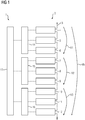
- a control device 1 for a converter 2 is shown.
- the converter 2 comprises a converter arm 3 in which a series connection of nine switching modules 4 to 12 is arranged.
- the control device 1 comprises a central unit 13 and a first, second and third sub-unit 14, 15 and 16, respectively.
- the central unit is connected to the sub-units 14-16 by means of bidirectional data lines.
- Each sub-unit 14-16 is assigned three of the switching modules 4-12, each sub-unit 14-16 being connected to the switching modules 4-6, 7-9 and 10-12 assigned to it, in turn, by means of bidirectional data lines.
- the switch modules 4-6 form a first group
- the switch modules 7-9 form a second group
- the switch modules 10-12 form a third group.
- a first sum voltage V1 is assigned to the first group
- a second sum voltage V2 is assigned to the second group
- a third sum voltage V3 is assigned to the third group.
- the sum voltages V1-3 add up to an arm voltage Vb.
- the converter comprises a converter arm, the converter arm comprising three groups of switching modules, each with three switching modules.
- the switching modules are each full-bridge switching modules, at the terminals of which a positive switching module voltage Vc, a negative switching module voltage -Vc and a zero voltage can be generated.
- Vc denotes the amount of the corresponding energy storage voltage.
- Each sub-unit carries out a pre-sorting for the group assigned to it.
- the aim is to find those switching modules whose status is to be changed next by switching from -1 to 0 and from 0 to 1, as well as to find those switching modules whose status is next from 1 to 0 and from 0 to -1 can be changed by suitable switching.
- the switching modules are sorted based on their status and based on their voltage.
- the sub-units transmit the information about the top two or the bottom two switching modules to the central unit. This carries out a sorting accordingly, as shown in the following table: Common list SM Vc status 1.3 1003.5 -1 3.1 977.2 0 3.6 977.3 0 2.3 984.2 0 1.1 991.3 0 2.4 996.4 0 3.2 1025.9 0 3.3 982.2 1 1.2 997.2 1 2.5 999.1 1 2.2 1016.3 1 1.5 1021.0 1
- the first two or the last two switching modules of the entire list are selected as those to be switched next.
- a corresponding method can also be carried out with other types of switching modules, such as, for example, the half-bridge switching modules known from the prior art.
- the method can also be used accordingly for an opposite direction of current (ib ⁇ 0).
- a power converter 20 is shown.
- the converter 20 comprises six converter arms 21-26, each of which is connected between one of the AC voltage connections 27-29 and one of the DC voltage poles 30, 31.
- a series circuit of switching modules 32 is arranged, the in the Figure 2
- the number of two switching modules shown per converter arm serves only as an example and can in principle be arbitrary and adapted to the respective application.
- the switch modules 32 are full bridge switch modules. Each switching module 32 accordingly comprises four semiconductor switches H1-H4 (IGBTs), each with free-wheeling diodes D1-D4 connected in anti-parallel. Furthermore, the switching module 32 comprises an energy store in the form of a capacitor K. Two connections X1, X2 are used to connect the switching module 32 to further elements of the converter 20. A control device 33 can, corresponding to the control device 1 of the Figure 1 be realized.
Landscapes
- Engineering & Computer Science (AREA)
- Power Engineering (AREA)
- Inverter Devices (AREA)
Abstract
Die Erfindung betrifft einen Stromrichter (2) mit einem Stromrichterarm (3), der eine Reihenschaltung von Nsm Schaltmodulen (4 - 12) aufweist, die jeweils steuerbare Halbleiterschalter und einen Energiespeicher umfassen, sowie mit einer Regelungseinrichtung (1) für eine Regelung des Stromrichters. Die Erfindung zeichnet sich dadurch aus, dass die Regelungseinrichtung eine Zentraleinheit (13) und eine Mehrzahl von Nu Untereinheiten (14 - 16) umfasst, die mit der Zentraleinheit verbunden sind, wobei jeder Untereinheit Ni Schalteinheiten zugeordnet sind, wobei jede Untereinheit dazu eingerichtet ist, an die Zentraleinheit eine Summenspannung der zugeordneten Schalteinheiten und/oder einen Schaltmodulstatus sowie eine Schaltmodulenergie einiger der zugeordneten Schalteinheiten zu übermitteln. Die Erfindung betrifft ferner ein Regelungsverfahren für den erfindungsgemäßen Stromrichter.The invention relates to a converter (2) with a converter arm (3) which has a series connection of Nsm switching modules (4-12), each comprising controllable semiconductor switches and an energy store, and with a control device (1) for regulating the converter. The invention is characterized in that the control device comprises a central unit (13) and a plurality of Nu sub-units (14-16) which are connected to the central unit, each sub-unit being assigned Ni switching units, each sub-unit being set up to to transmit a total voltage of the assigned switching units and / or a switching module status as well as a switching module energy of some of the assigned switching units to the central unit. The invention also relates to a control method for the converter according to the invention.
Description
Die Erfindung betrifft einen Stromrichter mit einem Stromrichterarm, der eine Reihenschaltung von Nsm Schaltmodulen aufweist, die jeweils steuerbare Halbleiterschalter und einen Energiespeicher umfassen, sowie mit einer Regelungseinrichtung für eine Regelung des Stromrichters.The invention relates to a converter with a converter arm which has a series connection of Nsm switching modules, each of which includes controllable semiconductor switches and an energy store, and with a control device for regulating the converter.
Ein solcher Stromrichter ist auch unter der Bezeichnung modularer Mehrstufenstromrichter (MMC) bekannt. MMC werden derzeit beispielsweise in Hochspannungsgleichstromübertragungssystemen (HGÜ) oder in Anlagen zur Netzstabilisierung (FACTS) eingesetzt.Such a converter is also known as a modular multi-stage converter (MMC). MMC are currently used, for example, in high-voltage direct current transmission systems (HVDC) or in systems for network stabilization (FACTS).
Die Energiespeicher der einzelnen Schaltmodule des MMC werden im betrieb des Stromrichters üblicherweise in einen Strompfad im zugehörigen Stromrichterarm zugeschaltet oder überbrückt, um eine durch die Regelung vorgegebene Armspannung zu erzeugen. Die Auswahl der zu schaltenden Schaltmodule wird gemäß einem implementierten Schaltalgorithmus durchgeführt. Die Zuschaltung bzw. Überbrückung des Energiespeichers wird mittels eines Einschaltens bzw. Sperrens der Halbleiterschalter des Schaltmoduls erreicht. Die Ansteuerung der Halbleiterschalter bzw. des Schaltmoduls übernimmt die Regelungseinrichtung im Sinne einer Ansteuereinheit, die mit einem Ansteuerbaustein des jeweiligen Schaltmoduls zusammenwirkt. Eine gleichmäßige Belastung bzw. Beanspruchung der Schaltmodule und insbesondere der Energiespeicher wird dadurch erreicht, dass der Schaltalgorithmus ein gleichmäßiges Schalten der Schaltmodule ermöglicht bzw. bewirkt. In diesem Zusammenhang wird von Balancierung der Energiespeicherspannungen der Energiespeicher bzw. deren Symmetrierung gesprochen.The energy stores of the individual switching modules of the MMC are usually connected or bridged in a current path in the associated converter arm when the converter is in operation, in order to generate an arm voltage specified by the control. The selection of the switching modules to be switched is carried out according to an implemented switching algorithm. The connection or bridging of the energy store is achieved by switching on or blocking the semiconductor switches of the switching module. The control of the semiconductor switches or the switching module is carried out by the control device in the sense of a control unit which interacts with a control component of the respective switching module. A uniform load or stress on the switching modules and in particular the energy storage is achieved in that the switching algorithm enables or effects a uniform switching of the switching modules. In this context, there is talk of balancing the energy storage voltages of the energy storage devices or their balancing.
Üblicherweise ist die Regelungseinrichtung über je eine Datenleitung mit jedem Schaltmodul verbunden, was mit einem enormen Aufwand verbunden ist, sowohl bei der Herstellung des Stromrichters als auch, wegen der großen ausgetauschten Datenmengen, in dessen Betrieb.Usually, the control device is connected to each switching module via a data line, which is associated with enormous effort, both in the manufacture of the Converter and, because of the large amounts of data exchanged, in its operation.
Die Aufgabe der Erfindung ist es, einen Stromrichter der eingangs genannten Art anzugeben, der möglichst kostengünstig und zuverlässig ist.The object of the invention is to specify a converter of the type mentioned at the beginning which is as inexpensive and reliable as possible.
Die Aufgabe wird bei einem artgemäßen Stromrichter erfindungsgemäß dadurch gelöst, dass die Regelungseinrichtung eine Zentraleinheit und eine Mehrzahl von Nu Untereinheiten umfasst, die mit der Zentraleinheit verbunden sind, wobei jeder Untereinheit Ni Schalteinheiten zugeordnet sind, so dass Nsm = summe (i=1...Nu)Ni gilt, wobei jede Untereinheit dazu eingerichtet ist, an die Zentraleinheit eine Summenspannung der zugeordneten Schalteinheiten und/oder einen Schaltmodulstatus sowie eine Schaltmodulenergie einiger der zugeordneten Schalteinheiten zu übermitteln. Demnach ist eine dezentralisierte Regelung bereitgestellt, bei der eine vorgegebene Anzahl der Schaltmodule je eine Untereinheit der Regelungseinrichtung zugeordnet ist. Diejenigen Schaltmodule eines und desselben Stromrichterarmes, die derselben Untereinheit zugeordnet sind, bilden somit eine Schaltmodulgruppe. Die Regelung bzw. Steuerung der zugeordneten Schaltmodule kann mittels dieser Untereinheit durchgeführt werden. Ein Vorteil der dezentralen Anordnung ist, dass die Zentraleinheit nicht mit jedem Schaltmodul mittels Datenleitungen verbunden sein muss. Vielmehr ist die Zentraleinheit lediglich mit den Untereinheiten mittels Datenleitungen verbunden, was einen Kostenvorteil gegenüber der üblichen Lösung ermöglicht. Die Untereinheiten können zweckmäßigerweise in einer örtlichen Nähe zu den zugeordneten Schaltmodulen angeordnet sein. Die Zentraleinheit kann an einem dazu geeigneten Ort im oder am Stromrichter angeordnet sein, wobei die Entfernung zwischen der Zentraleinheit und den Untereinheiten größer als die Entfernung zwischen den Untereinheiten und den ihnen zugeordneten Schaltmodulen sein kann. In einer solchen Konstellation ist der beschriebene Kostenvorteil besonders hoch. Die dezentrale Anordnung wird im Rahmen der Erfindung dazu genutzt, die Datenmenge der zwischen den Schaltmodulen und der Zentraleinheit ausgetauschten Daten zu reduzieren. Die einzelnen Schaltmodule senden ihre Zustandsdaten an die zugeordnete Untereinheit. Die Untereinheiten hingegen senden bereits bearbeitete Daten an die Zentraleinheit. Je nach Anwendung bzw. je nachdem, welches Regelungsverfahren implementiert ist, ist es im Rahmen der Erfindung ausreichend, wenn die Untereinheiten nur die Summenspannung der zugeordneten Schalteinheiten anstelle aller Schaltmodulspannungen an die Zentraleinheit übermitteln. Eine andere Möglichkeit ergibt sich daraus, dass zwar Status einzelner Schaltmodule an die Zentraleinheit übermittelt wird, allerdings nicht aller, sondern lediglich einiger der zugeordneten Schaltmodule. Die Untereinheiten brauchen insbesondere nicht untereinander verbunden zu sein.According to the invention, the object is achieved in a type of converter in that the control device comprises a central unit and a plurality of Nu sub-units which are connected to the central unit, each sub-unit Ni being assigned switching units, so that Nsm = sum (i = 1 .. .Nu) Ni applies, with each sub-unit being set up to transmit to the central unit a total voltage of the assigned switching units and / or a switching module status as well as a switching module energy of some of the assigned switching units. Accordingly, a decentralized control is provided in which a predetermined number of the switching modules is each assigned to a sub-unit of the control device. Those switching modules of one and the same converter arm which are assigned to the same subunit thus form a switching module group. The regulation or control of the assigned switching modules can be carried out by means of this sub-unit. One advantage of the decentralized arrangement is that the central unit does not have to be connected to each switching module by means of data lines. Rather, the central unit is only connected to the sub-units by means of data lines, which enables a cost advantage over the conventional solution. The subunits can expediently be arranged in close proximity to the assigned switching modules. The central unit can be arranged at a suitable location in or on the converter, wherein the distance between the central unit and the sub-units can be greater than the distance between the sub-units and the switching modules assigned to them. In such a constellation, the cost advantage described is particularly high. The decentralized arrangement is used within the scope of the invention to reduce the amount of data to reduce the data exchanged between the switching modules and the central unit. The individual switching modules send their status data to the assigned subunit. The sub-units, on the other hand, send data that have already been processed to the central unit. Depending on the application or depending on which control method is implemented, it is sufficient within the scope of the invention if the sub-units transmit only the total voltage of the assigned switching units instead of all switching module voltages to the central unit. Another possibility arises from the fact that the status of individual switching modules is transmitted to the central unit, but not all, but only some of the assigned switching modules. In particular, the subunits do not need to be connected to one another.
Gemäß einer Ausführungsform der Erfindung ist die Zentraleinheit dazu eingerichtet, jeweils einen zu stellenden Spannungsanteil an die Untereinheiten zu übermitteln. Demgemäß erfolgt die Regelung des Stromrichters, indem eine an dem wenigstens einen Stromrichterarm zu stellende Spannung mittels der Zentraleinheit ermittelt bzw. vorgegeben wird. Die Zentraleinheit ermittelt geeigneterweise aus der zu stellenden Spannung und der Information, die von den Untereinheiten übermittelt werden, welcher Spannungsanteil der gesamten zu stellenden Spannung durch welche Gruppe von Schaltmodulen zu stellen ist. Dieser ermittelte Spannungsanteil wird anschließend an die entsprechenden Untereinheiten übermittelt. Die Spannungsanteile summieren sich dabei zu der gesamten zu stellenden Spannung. Beispielsweise kann in einem Fall, wenn die Summenspannung einer der Gruppen der Schaltmodule unterhalb der durchschnittlichen Summenspannung aller Gruppen des Stromrichterarmes liegt, in Abhängigkeit von einem Strom ib durch den Stromrichterarm der zu stellende Spannungsanteil erhöht werden (falls ib>0) oder erniedrigt werden (falls ib<0) gegenüber dem zu stellenden Spannungsanteil derjenigen Gruppen mit einer überdurchschnittlichen Summenspannung.According to one embodiment of the invention, the central unit is set up to transmit a respective voltage component to be set to the subunits. Accordingly, the converter is regulated by determining or specifying a voltage to be set at the at least one converter arm by means of the central unit. The central unit appropriately determines from the voltage to be set and the information which is transmitted by the sub-units which voltage component of the total voltage to be set is to be set by which group of switching modules. This determined voltage component is then transmitted to the corresponding sub-units. The voltage components add up to the total voltage to be set. For example, in a case when the total voltage of one of the groups of the switching modules is below the average total voltage of all groups of the converter arm, depending on a current ib through the converter arm, the voltage component to be set can be increased (if ib> 0) or decreased (if ib <0) compared to the voltage share to be set for those groups with an above-average total voltage.
Geeigneterweise ist die Zentraleinheit dazu eingerichtet, jeweils eine zu schaltende Anzahl von Schaltmodulen an die Untereinheiten zu übermitteln. Demgemäß ermittelt die Zentraleinheit die Anzahl der Schaltmodule in jeder Gruppe des betreffenden Stromrichterarmes, die geschaltet (eingeschaltet und/oder abgeschaltet) werden sollen, um einer SollwertVorgabe der Regelung zu entsprechen. Aufgrund der übermittelten Information ermitteln die Untereinheiten jeweils selbsttätig, welche Schaltmodule ihrer zugeordneten Gruppe zu schalten sind. Im Rahmen der Erfindung wird ein Schaltmodul eingeschaltet, indem sein Energiespeicher in den Strompfad des Stromrichterarmes geschaltet wird. Es wird ausgeschaltet, indem sein Energiespeicher überbrückt oder auf eine andere Weise aus dem Strompfad genommen wird. Im Rahmen der Erfindung kann die Anzahl auch durch die Angabe einer mittlere Anzahl pro Zeitintervall gegeben sein, also insbesondere durch eine Bruchzahl, wie beispielsweise bei einer Anweisung, 6,72 Module in einem zeitlichen Mittel zu aktivieren.The central unit is suitably set up to transmit a number of switching modules to be switched to the subunits. Accordingly, the central unit determines the number of switching modules in each group of the relevant converter arm that are to be switched (switched on and / or switched off) in order to correspond to a setpoint value specified by the control system. On the basis of the information transmitted, the sub-units each automatically determine which switching modules of their assigned group are to be switched. In the context of the invention, a switching module is switched on by switching its energy storage device into the current path of the converter arm. It is switched off by bridging its energy store or removing it from the current path in some other way. Within the scope of the invention, the number can also be given by specifying an average number per time interval, that is to say in particular by a fraction, such as, for example, in the case of an instruction to activate 6.72 modules in a time average.
Es kann von Vorteil sein, wenn die Zentraleinheit dazu eingerichtet ist, jeweils eine Information über die zu schaltenden Schaltmodule an die Untereinheiten zu übermitteln. Beispielsweise kann jede Untereinheit gemäß der Vorgaben der Zentraleinheit eine Vorauswahl treffen, welche Schaltmodule zu einem gegebenen Zeitpunkt zu schalten sind und (nur) die Information über diese einigen ausgewählten Schaltmodule an die Zentraleinheit senden. Die Zentraleinheit ist zweckmäßigerweise dazu eingerichtet, aus den vor-ausgewählten Schaltmodulen aller betreffenden Untereinheiten diejenigen auszuwählen, die zu schalten sind. Die Information über diese zu schaltenden Schaltmodule (eines oder mehrere) können dann mittels der Zentraleinheit an die jeweilige zugeordnete Untereinheit (bzw. Untereinheiten) übermittelt werden.It can be advantageous if the central unit is set up to transmit information about the switching modules to be switched to the subunits. For example, according to the specifications of the central unit, each sub-unit can make a preselection which switching modules are to be switched at a given point in time and (only) send the information about these selected switching modules to the central unit. The central unit is expediently set up to select those which are to be switched from the preselected switching modules of all the relevant subunits. The information about these switching modules (one or more) to be switched can then be transmitted to the respective assigned subunit (or subunits) by means of the central unit.
Bevorzugt ist jede Untereinheit dazu eingerichtet, eine Spannungsbalancierung der dieser Untereinheit zugeordneten Schaltmodule durchzuführen. In der zugeordneten Gruppe von Schaltmodulen kann mittels der jeweiligen Untereinheit eines der dem Fachmann bekannten Balancierungsverfahren verwendet werden. Die Spannungsbalancierung dient dazu, die Energiespeicherspannungen der Schaltmodule möglichst gleich zu halten. Große Abweichungen zwischen Energiespeicherspannungen unterschiedlicher Schaltmodule führen zu einer unterschiedlichen Beanspruchung unterschiedlicher Energiespeicher und langfristig zu einem höheren Ausfallrisiko der betreffenden Schaltmodule. Geeigneterweise kann ein Energiespeicher in Abhängigkeit von der Stromrichtung durch den Stromrichterarm durch Zu- oder Abschalten gezielt auf- bzw. entladen werden. Die Wahl der Zeitpunkte des Schaltens eines Schaltmoduls und/oder der Schalthäufigkeit ermöglicht die Regelung der Energien bzw. Energiespeicherspannungen in den Schaltmodulen. Gemäß dieser Ausführungsform der Erfindung wird die Balancierung auf der Ebene der Gruppen der Schaltmodule dezentral mittels der Untereinheiten durchgeführt.Each sub-unit is preferably set up to carry out a voltage balancing of the switching modules assigned to this sub-unit. In the assigned group of switching modules, one can use the respective subunit the balancing method known to the person skilled in the art can be used. The voltage balancing is used to keep the energy storage voltages of the switching modules as equal as possible. Large deviations between energy storage voltages of different switching modules lead to different loads on different energy storage devices and, in the long term, to a higher risk of failure of the relevant switching modules. An energy store can suitably be charged or discharged in a targeted manner as a function of the current direction through the converter arm by switching it on or off. The choice of the times at which a switching module is switched and / or the switching frequency enables the energies or energy storage voltages in the switching modules to be regulated. According to this embodiment of the invention, the balancing is carried out at the level of the groups of switching modules in a decentralized manner by means of the subunits.
Vorzugsweise ist jede Untereinheit dazu eingerichtet, eine Sortierung unter den dieser Untereinheit zugeordneten Schaltmodulen auf der Basis von Schaltmodulstatus und/oder von Schaltmodulenergie durchzuführen. Die Sortierung kann zudem in Abhängigkeit von der Stromrichtung des Stromes durch den Stromrichterarm erfolgen. Die Sortierung erfolgt dabei zweckmäßigerweise gemäß dem Ziel, eine Balancierung der Energiespeicherspannungen zu erreichen. Die Sortierung bestimmt, welche Schaltmodule zu einem nächsten Zeitpunkt zu schalten sind, wobei der Status dieser Schaltmodule verändert wird. Es kann von Vorteil sein, wenn mittels der Sortierung eine Vorauswahl der zu schaltenden Schaltmodule getroffen wird. Mit anderen Worten werden einige der Schaltmodule der betreffenden Gruppe als Kandidaten für einen Schaltvorgang ausgewählt. Die Information über die Kandidaten (bspw. deren Status und/oder Energiespeicherspannung) können an die Zentraleinheit übermittelt werden. Auf diese Weise kann ein besonders wirksames Balancierungsverfahren bereitgestellt werden.Each sub-unit is preferably set up to sort among the switching modules assigned to this sub-unit on the basis of switching module status and / or switching module energy. The sorting can also take place depending on the direction of the current through the converter arm. The sorting is expediently carried out in accordance with the aim of balancing the energy storage voltages. The sorting determines which switching modules are to be switched at a next point in time, the status of these switching modules being changed. It can be advantageous if the switching modules to be switched are preselected by means of sorting. In other words, some of the switching modules of the group in question are selected as candidates for a switching process. The information about the candidates (for example their status and / or energy storage voltage) can be transmitted to the central unit. In this way, a particularly effective balancing method can be provided.
Gemäß einer Ausführungsform der Erfindung umfasst der Stromrichter wenigstens zwei Stromrichterarme mit jeweils einer Reihenschaltung der Schaltmodule, wobei wenigstens einer der Untereinheiten Schaltmodule aus zwei unterschiedlichen Stromrichterarmen zugeordnet sind. Bei dieser Variante der Erfindung ist der wenigstens einen Untereinheit eine erste Gruppe von Schaltmodulen zugeordnet, wobei die erste Gruppe sich aus Schaltmodulen zusammensetzt, die in einem ersten Stromrichterarm angeordnet sind. Ferner ist der wenigstens einen Untereinheit eine zweite Gruppe von Schaltmodulen zugeordnet, wobei die Schaltmodule der zweiten Gruppe in einem zweiten Stromrichterarm angeordnet ist. Die wenigstens eine Untereinheit ist insbesondere dazu eingerichtet, eine Spannungs- bzw. Energiebalancierung für jede der Gruppen einzeln und unabhängig durchzuführen. Es ist selbstredend denkbar, dass der Stromrichter weitere Stromrichterarme umfasst und der wenigstens einen Untereinheit eines oder mehrere Schaltmodule auch der weiteren Stromrichterarme zugeordnet sind. Je nach räumlicher Konfiguration des Stromrichters weist diese Variante Vorteile insbesondere bezüglich des Verkabelungsaufwandes.According to one embodiment of the invention, the converter comprises at least two converter arms, each with one Series connection of the switching modules, with at least one of the subunits being assigned to switching modules from two different converter arms. In this variant of the invention, the at least one subunit is assigned a first group of switching modules, the first group being composed of switching modules which are arranged in a first converter arm. Furthermore, the at least one sub-unit is assigned a second group of switching modules, the switching modules of the second group being arranged in a second converter arm. The at least one sub-unit is set up in particular to carry out a voltage or energy balancing for each of the groups individually and independently. It is of course conceivable that the converter comprises further converter arms and one or more switching modules of the further converter arms are also assigned to the at least one subunit. Depending on the spatial configuration of the converter, this variant has advantages, in particular with regard to the cabling effort.
Zweckmäßigerweise umfasst der Stromrichter sechs Stromrichterarme, die in einer Doppelsternschaltung zwischen einer Wechselspannungsseite und einer Gleichspannungsseite angeordnet sind. Je zwei der Stromrichterarme bilden ein sogenanntes Phasenmodul, indem die Stromrichterarme in Reihe zwischen einem ersten und einem zweiten Gleichspannungspol erstreckt sind. Zwischen den Stromrichterarmen desselben Phasenmoduls ist ein Wechselspannungsanschluss zum Verbinden mit einem Wechselspannungsnetz angeordnet. Somit umfasst die Doppelsternschaltung drei Phasenmodule zwischen dem ersten und dem zweiten Gleichspannungspol, wobei die Gleichspannungspole mit einer Gleichspannungsleitung beispielsweise eines Gleichspannungsnetzes verbindbar sind. Ein solcher Stromrichter ist als Gleichrichter und/oder Wechselrichter einsetzbar. Alternativ kann der Stromrichter beispielsweise drei Stromrichterarme umfassen, die in einer Dreieckschaltung oder einer Sternschaltung miteinander verbunden und als eine Netzstabilisierungseinrichtung (zum Beispiel ein Blindleistungskompensator) in Zusammenwirkung mit einem Wechselspannungsnetz einsetzbar sind.The converter expediently comprises six converter arms which are arranged in a double star connection between an AC voltage side and a DC voltage side. Two of the converter arms each form a so-called phase module in that the converter arms extend in series between a first and a second DC voltage pole. An AC voltage connection for connecting to an AC voltage network is arranged between the converter arms of the same phase module. The double star circuit thus comprises three phase modules between the first and the second DC voltage pole, the DC voltage poles being connectable to a DC voltage line, for example a DC voltage network. Such a converter can be used as a rectifier and / or inverter. Alternatively, the converter can comprise, for example, three converter arms that are connected to one another in a delta connection or a star connection and used as a network stabilization device (for example a reactive power compensator). can be used in cooperation with an alternating voltage network.
Vorzugsweise sind an Anschlüssen der Schaltmodule bipolare Spannungen erzeugbar. Mittels einer geeigneten Ansteuerung der Halbleiterschalter des Schaltmoduls können an den Anschlüssen (Anschlussklemmen) des Schaltmoduls zumindest eine positive Schaltmodulspannung, zumindest eine negative Schaltmodulspannung oder eine Nullspannung erzeugt werden. Geeigneterweise entspricht der Betrag der erzeugten Schaltmodulspannung einer an dem Energiespeicher des Schaltmoduls anstehenden Energiespeicherspannung. Ein Beispiel eines solchen Schaltmoduls ist das aus dem Stand der Technik bekannte Vollbrücken-Schaltmodul.Preferably, bipolar voltages can be generated at the connections of the switching modules. By means of a suitable control of the semiconductor switches of the switching module, at least one positive switching module voltage, at least one negative switching module voltage or a zero voltage can be generated at the connections (connecting terminals) of the switching module. Suitably, the amount of the switching module voltage generated corresponds to an energy storage voltage applied to the energy store of the switching module. An example of such a switching module is the full-bridge switching module known from the prior art.
Die Erfindung betrifft ferner ein Regelungsverfahren für einen Stromrichter mit einem Stromrichterarm, der eine Reihenschaltung von Nsm Schaltmodulen aufweist, die jeweils steuerbare Halbleiterschalter und einen Energiespeicher umfassen, sowie mit einer Regelungseinrichtung.The invention also relates to a control method for a converter with a converter arm which has a series connection of Nsm switching modules, each of which includes controllable semiconductor switches and an energy store, and with a control device.
Die Aufgabe der Erfindung besteht darin, ein solches Verfahren anzugeben, dass möglichst kostengünstig und zuverlässig ist.The object of the invention is to provide such a method that is as inexpensive and reliable as possible.
Die Aufgabe wird erfindungsgemäß dadurch gelöst, dass eine Regelungseinrichtung bereitgestellt wird, die eine Zentraleinheit und eine Mehrzahl von Nu Untereinheiten umfasst, die mit der Zentraleinheit verbunden sind, wobei jeder i-ten Untereinheit Ni Schalteinheiten zugeordnet sind, so dass Nsm = summe (i=l...Nu) Ni gilt, sowie dadurch, dass jede Untereinheit eine Summenspannung der zugeordneten Schalteinheiten und/oder einen Schaltmodulstatus sowie eine Schaltmodulenergie einiger der zugeordneten Schalteinheiten an die Zentraleinheit übermittelt.The object is achieved according to the invention in that a control device is provided which comprises a central unit and a plurality of Nu sub-units which are connected to the central unit, each i-th sub-unit Ni being assigned switching units, so that Nsm = sum (i = l.
Die Vorteile des erfindungsgemäßen Verfahrens ergeben sich insbesondere aus den bereits im Zusammenhang mit dem erfindungsgemäßen Stromrichter beschriebenen Vorteilen. Das Verfahren kann insbesondere entsprechend im Zusammenhang mit allen zuvor beschriebenen Ausführungsformen (allein oder in Kombination) des erfindungsgemäßen Stromrichters durchgeführt werden.The advantages of the method according to the invention result in particular from those already in connection with the method according to the invention Power converter described advantages. The method can in particular be carried out accordingly in connection with all of the previously described embodiments (alone or in combination) of the converter according to the invention.
Die Erfindung wird nachfolgend anhand von in den
-
Figur 1 zeigt ein Ausführungsbeispiel einer Reglerkonfiguration für den erfindungsgemäßen Stromrichter in einer schematischen Darstellung -
Figur 2 zeigt ein erfindungsgemäßes Ausführungsbeispiel eines Stromrichters in einer Doppelstern-Konfiguration.
-
Figure 1 shows an embodiment of a controller configuration for the converter according to the invention in a schematic representation -
Figure 2 shows an embodiment of a power converter according to the invention in a double-star configuration.
In der
Nachfolgend wird ein Beispiel für das erfindungsgemäße Verfahren in einer Anordnung der
Gemäß dem Beispiel umfasst der Stromrichter einen Stromrichterarm, wobei der Stromrichterarm drei Gruppen von Schaltmodulen mit jeweils drei Schaltmodulen umfasst. Die Schaltmodule sind jeweils Vollbrückenschaltmodule, an deren Anschlüssen jeweils eine positive Schaltmodulspannung Vc, eine negative Schaltmodulspannung -Vc sowie eine Nullspannung erzeugbar sind. Der Zustand des jeweiligen Schaltmoduls bezüglich der Schalmodulspannung wird im Folgenden durch 1, -1 und 0 abgekürzt. Vc bezeichnet den Betrag der entsprechenden Energiespeicherspannung. Es wird zudem zur Erklärungszwecken vorausgesetzt, dass für den Strom ib durch den Stromrichterarm gilt, dass ib>0. Als Beispielwerte werden folgende Spannungen der Schaltmodule SM angenommen:
Jede Untereinheit führt für die ihr zugeordnete Gruppe eine Vor-Sortierung durch. Das Ziel ist es, diejenigen Schaltmodule zu finden, deren Status als nächstes durch Schalten von -1 auf 0 und von 0 auf 1 zu ändern ist, sowie diejenigen Schaltmodule zu finden, deren Status als nächstes von 1 auf 0 und von 0 auf -1 durch geeignetes Schalten zu ändern ist. Die Schaltmodule werden bezogen auf ihren Status und bezogen auf ihre Spannung sortiert. Das Ergebnis ist dementsprechend:
Die Untereinheiten übermitteln die Information über die obersten beiden bzw. die untersten beiden Schaltmodule an die Zentraleinheit. Diese führt dementsprechend eine Sortierung durch, wie in der nachfolgenden Tabelle dargestellt:
Gemäß dem hier dargestellten Beispiel werden die ersten beiden bzw. die letzten beiden Schaltmodule der gesamten Liste als diejenigen ausgewählt, die als nächstes zu schalten sind.According to the example shown here, the first two or the last two switching modules of the entire list are selected as those to be switched next.
Ein entsprechendes Verfahren kann auch bei anderen Typen von Schaltmodulen durchgeführt werden, wie beispielsweise den aus dem Stand der Technik bekannten Halbbrücken-Schaltmodulen.A corresponding method can also be carried out with other types of switching modules, such as, for example, the half-bridge switching modules known from the prior art.
Auch bei einer entgegengesetzten Stromrichtung (ib<0) ist das Verfahren entsprechend anwendbar.The method can also be used accordingly for an opposite direction of current (ib <0).
In
Die Schaltmodule 32 sind Vollbrücken-Schaltmodule. Jedes Schaltmodul 32 umfasst dementsprechend vier Halbleiterschalter H1-H4 (IGBTs) mit jeweils antiparallel geschalteten Freilaufdioden D1-D4. Ferner umfasst das Schaltmodul 32 einen Energiespeicher in Form eines Kondensators K. Zwei Anschlüsse X1, X2 dienen zum Verbinden des Schaltmoduls 32 mit weiteren Elementen des Stromrichters 20. Eine Regelungseinrichtung 33 kann entsprechend der Regelungseinrichtung 1 der
Claims (10)
dadurch gekennzeichnet, dass
die Regelungseinrichtung (1) eine Zentraleinheit (13) und eine Mehrzahl von Nu Untereinheiten (14 - 16) umfasst, die mit der Zentraleinheit (13) verbunden sind, wobei jeder i-ten Untereinheit Ni Schaltmodule zugeordnet sind, wobei jede Untereinheit (14 - 16) dazu eingerichtet ist, an die Zentraleinheit (13)
characterized in that
the control device (1) comprises a central unit (13) and a plurality of Nu sub-units (14 - 16) which are connected to the central unit (13), each i-th sub-unit being assigned Ni switching modules, each sub-unit (14 - 16) is set up to be connected to the central unit (13)
wobei die Zentraleinheit (13) dazu eingerichtet ist, jeweils einen zu stellenden Spannungsanteil an die Untereinheiten (14 - 16) zu übermitteln.Converter (2) according to claim 1,
wherein the central unit (13) is set up to transmit a respective voltage component to be set to the sub-units (14-16).
wobei die Zentraleinheit (13) dazu eingerichtet ist, jeweils eine zu schaltende Anzahl von Schaltmodulen (4 - 12) an die Untereinheiten (14 - 16) zu übermitteln.Converter (2) according to one of the preceding claims,
wherein the central unit (13) is set up to transmit a number of switching modules (4-12) to be switched to the sub-units (14-16).
wobei die Zentraleinheit (13) dazu eingerichtet ist, jeweils eine Information über die zu schaltenden Schaltmodule (4 - 12) an die Untereinheiten (14 - 16) zu übermitteln.Converter (2) according to one of the preceding claims,
wherein the central unit (13) is set up to transmit information about the switching modules (4-12) to be switched to the sub-units (14-16).
wobei jede Untereinheit (14 - 16) dazu eingerichtet ist, eine Spannungsbalancierung der dieser Untereinheit (14 - 16) zugeordneten Schaltmodule durchzuführen.Converter (2) according to one of the preceding claims,
each sub-unit (14-16) being set up to carry out a voltage balancing of the switching modules assigned to this sub-unit (14-16).
wobei jede Untereinheit (14 - 16) dazu eingerichtet ist, eine Sortierung unter den dieser Untereinheit zugeordneten Schaltmodulen auf der Basis von Schaltmodulstatus und/oder von Schaltmodulenergie durchzuführen.Converter (2) to one of the preceding claims,
each sub-unit (14-16) being set up to sort among the switching modules assigned to this sub-unit on the basis of switching module status and / or switching module energy.
wobei der Stromrichter wenigstens zwei Stromrichterarme mit jeweils einer Reihenschaltung der Schaltmodule umfasst, wobei wenigstens einer der Untereinheiten Schaltmodule aus zwei unterschiedlichen Stromrichterarmen zugeordnet sind.Converter (2) according to one of the preceding claims,
wherein the converter comprises at least two converter arms, each with a series connection of the switching modules, with at least one of the subunits being assigned to switching modules from two different converter arms.
wobei der Stromrichter (2) sechs Stromrichterarme umfasst, die in einer Doppelsternschaltung zwischen einer Wechselspannungsseite und einer Gleichspannungsseite angeordnet sind.Converter (2) according to one of the preceding claims,
wherein the converter (2) comprises six converter arms which are arranged in a double star connection between an AC voltage side and a DC voltage side.
wobei an Anschlüssen der Schaltmodule (4 - 12) bipolare Spannungen erzeugbar sind.Converter (2) according to one of the preceding claims,
wherein bipolar voltages can be generated at the connections of the switching modules (4 - 12).
bei dem
jede Untereinheit (14 - 16)
in which
each subunit (14 - 16)
Priority Applications (1)
| Application Number | Priority Date | Filing Date | Title |
|---|---|---|---|
| EP20160591.2A EP3876410A1 (en) | 2020-03-03 | 2020-03-03 | Power converter and control method thereof |
Applications Claiming Priority (1)
| Application Number | Priority Date | Filing Date | Title |
|---|---|---|---|
| EP20160591.2A EP3876410A1 (en) | 2020-03-03 | 2020-03-03 | Power converter and control method thereof |
Publications (1)
| Publication Number | Publication Date |
|---|---|
| EP3876410A1 true EP3876410A1 (en) | 2021-09-08 |
Family
ID=69770428
Family Applications (1)
| Application Number | Title | Priority Date | Filing Date |
|---|---|---|---|
| EP20160591.2A Pending EP3876410A1 (en) | 2020-03-03 | 2020-03-03 | Power converter and control method thereof |
Country Status (1)
| Country | Link |
|---|---|
| EP (1) | EP3876410A1 (en) |
Citations (3)
| Publication number | Priority date | Publication date | Assignee | Title |
|---|---|---|---|---|
| WO2008067784A1 (en) * | 2006-12-08 | 2008-06-12 | Siemens Aktiengesellschaft | Control of a modular power converter with distributed energy accumulators |
| US20140002048A1 (en) * | 2011-03-21 | 2014-01-02 | China Electric Power Research Institute | Voltage balancing control method for modular multilevel converter |
| WO2017207045A1 (en) * | 2016-06-01 | 2017-12-07 | Abb Schweiz Ag | Modular multilevel converter cell with integrated current sensor |
-
2020
- 2020-03-03 EP EP20160591.2A patent/EP3876410A1/en active Pending
Patent Citations (3)
| Publication number | Priority date | Publication date | Assignee | Title |
|---|---|---|---|---|
| WO2008067784A1 (en) * | 2006-12-08 | 2008-06-12 | Siemens Aktiengesellschaft | Control of a modular power converter with distributed energy accumulators |
| US20140002048A1 (en) * | 2011-03-21 | 2014-01-02 | China Electric Power Research Institute | Voltage balancing control method for modular multilevel converter |
| WO2017207045A1 (en) * | 2016-06-01 | 2017-12-07 | Abb Schweiz Ag | Modular multilevel converter cell with integrated current sensor |
Non-Patent Citations (1)
Similar Documents
| Publication | Publication Date | Title |
|---|---|---|
| DE102008014898B4 (en) | Method for controlling a multiphase power converter with distributed energy stores at low output frequencies | |
| EP3496259B1 (en) | Electrical converter system | |
| DE69519984T2 (en) | Control system for electric vehicles | |
| EP2596980B1 (en) | Multiple point frequency converter with brake chopper | |
| EP3245727B1 (en) | Converter module for a multi-level energy converter | |
| EP3361598A2 (en) | Balancing device for a batterie in a converter assembly | |
| EP2807738B1 (en) | Multicell converter | |
| WO2019101305A1 (en) | Converter and operation thereof | |
| EP3683950A1 (en) | Method for the control of a modular multilevel converter with half- and fullbridge cells | |
| EP3713073A1 (en) | Converter and method for controlling same | |
| DE102005026338A1 (en) | Uninterruptible power supply and control method for this | |
| DE102012218738A1 (en) | Charging system as satellite charging system for electric car, has charging portions to charge batteries through power supply terminal and direct current regulators, where one regulator is optionally connected to two charging portions | |
| DE102015222280A1 (en) | Modular multi-stage converter and method for operating a modular multi-stage converter | |
| DE102017220599A1 (en) | Converter arrangement for stabilizing an AC voltage network | |
| EP3876410A1 (en) | Power converter and control method thereof | |
| EP3485563B1 (en) | Converter assembly and method for operating same | |
| EP3751718B1 (en) | Method for handling of a fault in a direct current line and inverter assembly for implementing the method | |
| EP3656032A1 (en) | Series compensation device | |
| DE3826283C2 (en) | Mains converter for a multi-system multiple unit | |
| DE102020131349B3 (en) | Circuit arrangement and method for controlling and activating the connection of electrical equipment and / or power line sections | |
| EP3363091B1 (en) | Device and method for controlling a load flow in an alternating-voltage network | |
| WO2022078825A1 (en) | Controller | |
| WO2014076138A1 (en) | Converter | |
| WO2018113926A1 (en) | Power converter | |
| EP3741023B1 (en) | Device and method for controlling a load flow in an alternating-voltage network |
Legal Events
| Date | Code | Title | Description |
|---|---|---|---|
| PUAI | Public reference made under article 153(3) epc to a published international application that has entered the european phase |
Free format text: ORIGINAL CODE: 0009012 |
|
| STAA | Information on the status of an ep patent application or granted ep patent |
Free format text: STATUS: THE APPLICATION HAS BEEN PUBLISHED |
|
| AK | Designated contracting states |
Kind code of ref document: A1 Designated state(s): AL AT BE BG CH CY CZ DE DK EE ES FI FR GB GR HR HU IE IS IT LI LT LU LV MC MK MT NL NO PL PT RO RS SE SI SK SM TR |
|
| STAA | Information on the status of an ep patent application or granted ep patent |
Free format text: STATUS: REQUEST FOR EXAMINATION WAS MADE |
|
| 17P | Request for examination filed |
Effective date: 20220308 |
|
| RBV | Designated contracting states (corrected) |
Designated state(s): AL AT BE BG CH CY CZ DE DK EE ES FI FR GB GR HR HU IE IS IT LI LT LU LV MC MK MT NL NO PL PT RO RS SE SI SK SM TR |
|
| RAP3 | Party data changed (applicant data changed or rights of an application transferred) |
Owner name: SIEMENS ENERGY GLOBAL GMBH & CO. KG |
|
| RAP3 | Party data changed (applicant data changed or rights of an application transferred) |
Owner name: SIEMENS ENERGY GLOBAL GMBH & CO. KG |
|
| STAA | Information on the status of an ep patent application or granted ep patent |
Free format text: STATUS: EXAMINATION IS IN PROGRESS |
|
| 17Q | First examination report despatched |
Effective date: 20230523 |