EP3876399A1 - Motor comprising a built-in fan - Google Patents
Motor comprising a built-in fan Download PDFInfo
- Publication number
- EP3876399A1 EP3876399A1 EP21160990.4A EP21160990A EP3876399A1 EP 3876399 A1 EP3876399 A1 EP 3876399A1 EP 21160990 A EP21160990 A EP 21160990A EP 3876399 A1 EP3876399 A1 EP 3876399A1
- Authority
- EP
- European Patent Office
- Prior art keywords
- motor
- auxiliary
- engine
- fan
- main
- Prior art date
- Legal status (The legal status is an assumption and is not a legal conclusion. Google has not performed a legal analysis and makes no representation as to the accuracy of the status listed.)
- Granted
Links
- 238000009423 ventilation Methods 0.000 claims description 28
- 238000001816 cooling Methods 0.000 claims description 27
- 238000011144 upstream manufacturing Methods 0.000 claims description 2
- 235000021183 entrée Nutrition 0.000 description 8
- 230000004907 flux Effects 0.000 description 6
- 241000940835 Pales Species 0.000 description 4
- 206010033546 Pallor Diseases 0.000 description 4
- 230000002093 peripheral effect Effects 0.000 description 3
- 238000002955 isolation Methods 0.000 description 1
- XLYOFNOQVPJJNP-UHFFFAOYSA-N water Substances O XLYOFNOQVPJJNP-UHFFFAOYSA-N 0.000 description 1
Images


Classifications
-
- H—ELECTRICITY
- H02—GENERATION; CONVERSION OR DISTRIBUTION OF ELECTRIC POWER
- H02K—DYNAMO-ELECTRIC MACHINES
- H02K9/00—Arrangements for cooling or ventilating
- H02K9/02—Arrangements for cooling or ventilating by ambient air flowing through the machine
- H02K9/04—Arrangements for cooling or ventilating by ambient air flowing through the machine having means for generating a flow of cooling medium
-
- H—ELECTRICITY
- H02—GENERATION; CONVERSION OR DISTRIBUTION OF ELECTRIC POWER
- H02K—DYNAMO-ELECTRIC MACHINES
- H02K7/00—Arrangements for handling mechanical energy structurally associated with dynamo-electric machines, e.g. structural association with mechanical driving motors or auxiliary dynamo-electric machines
- H02K7/20—Structural association with auxiliary dynamo-electric machines, e.g. with electric starter motors or exciters
-
- H—ELECTRICITY
- H02—GENERATION; CONVERSION OR DISTRIBUTION OF ELECTRIC POWER
- H02K—DYNAMO-ELECTRIC MACHINES
- H02K1/00—Details of the magnetic circuit
- H02K1/06—Details of the magnetic circuit characterised by the shape, form or construction
- H02K1/12—Stationary parts of the magnetic circuit
- H02K1/20—Stationary parts of the magnetic circuit with channels or ducts for flow of cooling medium
-
- H—ELECTRICITY
- H02—GENERATION; CONVERSION OR DISTRIBUTION OF ELECTRIC POWER
- H02K—DYNAMO-ELECTRIC MACHINES
- H02K7/00—Arrangements for handling mechanical energy structurally associated with dynamo-electric machines, e.g. structural association with mechanical driving motors or auxiliary dynamo-electric machines
- H02K7/14—Structural association with mechanical loads, e.g. with hand-held machine tools or fans
-
- H—ELECTRICITY
- H02—GENERATION; CONVERSION OR DISTRIBUTION OF ELECTRIC POWER
- H02K—DYNAMO-ELECTRIC MACHINES
- H02K9/00—Arrangements for cooling or ventilating
- H02K9/02—Arrangements for cooling or ventilating by ambient air flowing through the machine
- H02K9/04—Arrangements for cooling or ventilating by ambient air flowing through the machine having means for generating a flow of cooling medium
- H02K9/06—Arrangements for cooling or ventilating by ambient air flowing through the machine having means for generating a flow of cooling medium with fans or impellers driven by the machine shaft
-
- H—ELECTRICITY
- H02—GENERATION; CONVERSION OR DISTRIBUTION OF ELECTRIC POWER
- H02K—DYNAMO-ELECTRIC MACHINES
- H02K9/00—Arrangements for cooling or ventilating
- H02K9/14—Arrangements for cooling or ventilating wherein gaseous cooling medium circulates between the machine casing and a surrounding mantle
- H02K9/16—Arrangements for cooling or ventilating wherein gaseous cooling medium circulates between the machine casing and a surrounding mantle wherein the cooling medium circulates through ducts or tubes within the casing
Definitions
- the present invention relates to a motor comprising a main stator, a main rotor, and a main motor shaft, the motor comprising an integrated fan comprising blades movable in rotation about an axis coaxial with the main motor shaft.
- the motor comprises a housing delimiting an internal volume comprising the main stator, the main rotor and a part of the motor shaft and that the fan is included in the internal volume delimited by the housing.
- Motors comprising an integrated fan, in which the fan is fixed to the motor shaft and comprises blades movable in rotation around the motor shaft. Thus, the rotation of the motor shaft drives the rotation of the fan.
- An air inlet duct is placed between the fan and the motor perpendicular to the longitudinal direction and opening into longitudinal openings in the stator.
- One of the aims of the invention is to overcome the drawbacks mentioned above, in particular by proposing an integrated fan motor that is more compact and efficient than the integrated fan motors of the state of the art.
- the present invention relates to a motor of the aforementioned type, the motor comprising an auxiliary motor associated with the fan, the auxiliary motor comprising an auxiliary stator, an auxiliary rotor, and an auxiliary motor shaft integral in rotation with the blades of the fan. , fixed to the auxiliary rotor and guided in rotation by means of auxiliary bearings mounted on the auxiliary stator.
- the subject of the invention is also a vehicle, in particular a railway vehicle, comprising an engine according to the invention.
- the Figure 1 shows a motor 10 according to a first embodiment of the invention.
- Motor 10 is preferably a traction motor.
- the engine 10 is for example an engine of a land, air or water vehicle.
- the engine 10 is a land vehicle engine, in particular a public transport vehicle or an automobile.
- the public transport vehicle is for example a rail vehicle, a tram, or a bus.
- the public transport vehicle is a railway vehicle.
- the motor 10 includes a main frame 11, a main stator 12, a main motor shaft 14, a main rotor 16 fixed to the main motor shaft 14, an integrated fan 20 and an auxiliary motor 22 associated with the fan 20.
- the main motor shaft is guided in rotation by means of bearings 18 mounted on the main stator 12.
- the main motor shaft 14 extends mainly in a longitudinal direction L and it is movable in rotation about an axis X1 parallel to the longitudinal direction L.
- the motor 10 has, in the longitudinal direction L, a drive side E intended to be arranged on the side of an item of equipment to be driven and a side opposite to the drive O.
- the main rotor 16 surrounds the main motor shaft 14.
- the main stator 12 surrounds the main rotor 16 and carries a set of coils 23.
- the motor 10 comprises an air inlet flange 24 on the side opposite to the drive O.
- the motor 10 includes an air outlet flange 25 on the drive side E.
- the air inlet flange 24 and the air outlet flange 25 extend mainly in a transverse direction T perpendicular to the longitudinal direction L.
- the motor 10 typically has a plurality of ventilation channels 26 substantially parallel to the longitudinal direction L.
- the ventilation channels 26 are delimited in the main frame 11 outside the main stator 12, in particular around the main stator 12.
- the fan 20 is placed on the side opposite to the drive O.
- the fan 20 comprises blades 27 movable in rotation about an axis X2 coaxial with the main motor shaft 14.
- the blades 27 are for example arranged on a structure 29 of the fan 20 in the general form of a disc.
- the blades 27 are oriented towards the side opposite to the drive O of the motor 10. Preferably, the blades 27 are arranged at regular intervals.
- the fan 20 comprises twelve blades 27. In a variant not shown, the fan 20 comprises a different number of blades 27.
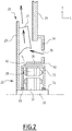
- the auxiliary motor 22 according to the first embodiment shown in Figure 2 comprises an auxiliary stator 28, an auxiliary rotor 32, and an auxiliary motor shaft 30 integral in rotation with the blades 27 of the fan 20, fixed to the auxiliary rotor 32 coaxially with the main motor shaft 14, and guided in rotation with the aid of auxiliary bearings 33 mounted on the auxiliary stator 28.
- the auxiliary motor shaft 30 is arranged in the extension of the main motor shaft 14 in the longitudinal direction L.
- the auxiliary motor shaft 30 is for example arranged at a distance from the main motor shaft 14 of between 1 mm and 5 mm.
- the auxiliary motor 22 has dimensions 5 to 10 times smaller than the dimensions of the motor 10.
- the auxiliary motor 22 is compact and does not encumber the motor 10.
- the fan 20 operates in high flow, that is to say that pressurizing the fan 20 causes the air to circulate downstream of the pressurization from an inlet zone of. air located in front of the air inlet flange 24 towards the rear of the air inlet flange 24 then in the ventilation channels 26 of the engine 10.
- the auxiliary motor 22 comprises a part 34 for fixing the auxiliary motor 22 to the main frame 11 of the motor 10.
- the auxiliary motor 22 comprises an auxiliary frame 35.
- the attachment 34 of the auxiliary motor 22 to the main frame 11 of the motor 10 defines at least one orifice 36.
- the orifice 36 allows air to enter the motor 10 and to cool it.
- the attachment piece 34 of the auxiliary motor 22 to the main frame 11 of the motor 10 defines a plurality of orifices 36.
- the orifices 36 typically have a total surface area of between 200 cm 2 and 1000 cm 2 .
- the attachment piece 34 of the auxiliary motor 22 to the engine 10 defines with the auxiliary frame 35 at least one channel 38 for cooling the auxiliary motor 22.
- the cooling channel 38 of the auxiliary motor 22 is substantially parallel to the longitudinal direction L.
- the cooling channel 38 of the auxiliary motor 22 opens at a first end 40 to the outside of the motor 10 on the side opposite to the drive O.
- the cooling channel 38 of the auxiliary motor 22 opens at a second end 42 behind the air inlet flange 24.
- the attachment piece 34 of the auxiliary motor 22 to the engine 10 defines with the auxiliary frame 35 a plurality of cooling channels 38 for the auxiliary motor 22 distributed regularly around the auxiliary frame 35.
- the cooling channels 38 of the auxiliary motor 22 typically have a cross section with a total surface area of between 50 cm 2 and 200 cm 2 .
- the motor 10 comprises, as shown in Figure 3 , from the periphery to the center: the main frame 11 pierced with oblong holes 44 forming the ventilation channels 26, the air inlet flange 24 of the engine 10, the attachment part 34 of the auxiliary engine 22 to the engine 10 , the auxiliary frame 35 of the auxiliary motor 22 forming protrusions 46 at its periphery, these protrusions 46 defining with the fixing part 34 the cooling channels 38 of the auxiliary motor 22, and the auxiliary motor shaft 30.
- each ventilation channel 26 and in each cooling channel 38 schematically shows the flow of air passing through these channels.
- the fan 20 is used both to create a main air flow to cool the motor 10 but also a secondary air flow to cool the auxiliary motor 22 which is used for its drive.
- the fan 20 allows circulation of the main air flow from the air inlet zone, passing successively through the orifices 36, the blades 27 of the fan 20, then through the ventilation channels 26, and in emerging from the drive side E and a circulation of the secondary air flow from the air inlet zone, passing successively through the cooling channels 38, then through the blades 27 of the fan 20, then through the ventilation channels 26, and leaving the drive side E.
- the main and secondary air flows meet in particular at the level of the fan 20 and its blades 27.
- the Figure 4 shows a motor 110 according to a second embodiment of the invention, described by difference from the first embodiment.
- the numbering of the elements common to the first embodiment is carried out by adding 100 to each reference numeral with respect to the first embodiment.
- the motor 110 of the second embodiment differs mainly from the motor 10 of the first embodiment in that the fan 120 operates in pull-out mode.
- the motor 110 includes an air inlet flange 124 on the drive side E.
- the motor 110 comprises an air outlet flange 125 on the side opposite to the drive O.
- the blades 127 of the fan 120 are oriented towards the drive side E of the motor 110.
- the auxiliary motor shaft 130 is for example arranged at a distance from the main motor shaft 114 of between 1 mm and 50 mm.
- the fastener 134 is preferably devoid of orifices.
- orifices 150 are formed in the structure 129 of the fan 120.
- the orifices 150 are preferably arranged to be aligned with each cooling channel 138 of the auxiliary motor 122 when the fan 120 is in operation. This makes it possible to create an air circulation during the pressurization of the fan 120.
- Each cooling channel 138 of the auxiliary motor 122 opens at a first end 140 to the outside of the motor 110 on the side opposite to the drive O.
- Each cooling channel 138 of the auxiliary motor 122 opens at a second end 142 behind the air outlet flange 125, at the level of the orifices 150 and therefore of the fan 120 and of its blades 127.
- the engine 110 in cross section shown in Figure 6 comprises, from the periphery towards the center: the air outlet flange 125 of the engine 110, the attachment piece 134 of the auxiliary engine 122 to the engine 110, the auxiliary frame 135 of the auxiliary engine 122 forming projections 146 at its periphery, delimiting with the fixing part 134 the cooling channels 138 of the auxiliary motor 122, and the auxiliary motor shaft 130.
- the Figures 7 and 8 show in more detail the fan 120 and the blades 127.
- the structure 129 of the fan 120 has a peripheral zone 152 provided with the blades 127 and a central zone 154 devoid of blades.
- the orifices 150 formed in the structure 129 of the fan 120 are arranged between the central zone 154 and the peripheral zone 152 of the structure 129 of the fan 120.
- the orifices 150 typically have a width taken between the central zone 154 and the peripheral zone. 152 between 5 mm and 20 mm.
- the auxiliary motor 122 and the motor 110 have separate air inlets provided on opposite sides O, E of the motor 110, and pressurizing the fan 120 allows a main air flow to be drawn from the side d. 'drive E, opposite the fan 120.
- This main air flow passes successively from an air inlet zone located on the drive side, then through the ventilation channels 126, between the main frame 111 and the main stator 112, then passes through fan 120 to an air outlet oriented perpendicular to the longitudinal direction L.
- the main air flow allows the motor 110 to be cooled.
- the main air flow passes between the main stator 112 and the main rotor 116 if the motor 110 is open.
- a secondary air flow passes through the cooling channel 138 of the auxiliary engine 122.
- the secondary air flow passes successively from an air collection zone located on the side opposite to the drive O, then through the cooling channels 138, then through the orifices 150, then joins the main flow at the level of the fan 120 before coming into contact with the blades 127, then passes through the fan 120 to the air outlet oriented perpendicular to the longitudinal direction L.
- the main air flow and the secondary air flow mix before coming into contact with the blades 127 of the fan 120. This makes it possible to limit the disturbances of the total air flow seen by the fan 120, as is usual. represented by the arrows on the Figure 4 .
- the two air flows are evacuated outside the engine 110 substantially perpendicular to the longitudinal direction L.
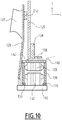
- the Figure 9 shows a motor 210 according to a third embodiment of the invention, which is a variant of the second embodiment.
- the motor 210 of the third embodiment operates in pull-flow.
- the motor 210 of the third embodiment differs in particular from the motor 110 of the second embodiment in that the fan 120 comprises, in addition to the blades 127 oriented towards the drive side E of the motor 210, secondary blades 212 oriented towards the side. opposed to training O.
- the secondary blades 212 are arranged on the structure 129 of the fan 120 on the side opposite the blades 127.
- the secondary blades 212 are advantageously smaller than the blades 127, and are intended to ventilate the auxiliary motor 122.
- the motor 210 of the third embodiment also differs from the motor 110 of the second embodiment in that the structure 129 of the fan 120 is devoid of orifices.
- Each cooling channel 138 of the auxiliary motor 122 opens out at a second end 142 behind the air outlet flange 125, at the level of the structure 129 of the fan 120.
- the auxiliary motor 122 and the motor 210 have separate air inlets provided on opposite sides O, E of the motor 210, and pressurizing the fan 120 allows a main air flow to be drawn from the side d. 'drive E, opposite the fan 120.
- This main air flow passes successively from an air inlet zone located on the drive side, then through the ventilation channels 126, between the main frame 111 and the main stator 112, then passes through fan 120 to an air outlet oriented perpendicular to the longitudinal direction L.
- the main air flow allows the motor 110 to be cooled.
- the main air flow passes between the main stator 112 and the main rotor 116 if the motor 110 is open.
- a secondary air flow passes through the cooling channel 138 of the auxiliary engine 122.
- the secondary air flow passes successively from an air collection zone located on the side opposite to the drive O, then through the cooling channels 138, then at the level of the fan 120 before coming into contact with the elements. secondary blades 212, then passes through the fan 120 to the air outlet oriented perpendicular to the longitudinal direction L.
- the two air flows are evacuated outside the engine 110 substantially perpendicular to the longitudinal direction L.
- the motor according to the invention therefore comprises a very compact and high performance integrated fan.
- the fan provides efficient cooling of the auxiliary motor in order to make it compact and integrable in a constrained environment such as a bogie.
Landscapes
- Engineering & Computer Science (AREA)
- Power Engineering (AREA)
- Motor Or Generator Cooling System (AREA)
- Structures Of Non-Positive Displacement Pumps (AREA)
- Connection Of Motors, Electrical Generators, Mechanical Devices, And The Like (AREA)
Abstract
L'invention concerne un moteur (10) comprenant un stator principal (12), un rotor principal (16), et un arbre moteur principal (14), le moteur (10) comprenant un ventilateur (20) intégré comportant des pales (27) mobiles en rotation autour d'un axe (X2) coaxial à l'arbre moteur principal (14), le moteur comportant un moteur auxiliaire (22) associé au ventilateur (20), le moteur auxiliaire (22) comprenant un stator auxiliaire (28), un rotor auxiliaire (32), et un arbre moteur auxiliaire (30) solidaire en rotation des pales (27) du ventilateur (20), fixé au rotor auxiliaire (32) et guidé en rotation l'aide de roulements auxiliaires (33) montés sur le stator auxiliaire (28).The invention relates to a motor (10) comprising a main stator (12), a main rotor (16), and a main motor shaft (14), the motor (10) comprising an integrated fan (20) having blades (27). ) movable in rotation about an axis (X2) coaxial with the main motor shaft (14), the motor comprising an auxiliary motor (22) associated with the fan (20), the auxiliary motor (22) comprising an auxiliary stator ( 28), an auxiliary rotor (32), and an auxiliary motor shaft (30) integral in rotation with the blades (27) of the fan (20), fixed to the auxiliary rotor (32) and guided in rotation using auxiliary bearings ( 33) mounted on the auxiliary stator (28).
Description
La présente invention concerne un moteur comprenant un stator principal, un rotor principal, et un arbre moteur principal, le moteur comprenant un ventilateur intégré comportant des pales mobiles en rotation autour d'un axe coaxial à l'arbre moteur principal.The present invention relates to a motor comprising a main stator, a main rotor, and a main motor shaft, the motor comprising an integrated fan comprising blades movable in rotation about an axis coaxial with the main motor shaft.
Par « ventilateur intégré », il est entendu que le moteur comprend un boîtier délimitant un volume intérieur comprenant le stator principal, le rotor principal et une partie de l'arbre moteur et que le ventilateur est compris dans le volume intérieur délimité par le boîtier.By “integrated fan”, it is understood that the motor comprises a housing delimiting an internal volume comprising the main stator, the main rotor and a part of the motor shaft and that the fan is included in the internal volume delimited by the housing.
On connaît des moteurs comprenant un ventilateur intégré, dans lesquels le ventilateur est fixé à l'arbre du moteur et comporte des pales mobiles en rotation autour de l'arbre moteur. Ainsi, la rotation de l'arbre moteur entraîne la rotation du ventilateur.Motors are known comprising an integrated fan, in which the fan is fixed to the motor shaft and comprises blades movable in rotation around the motor shaft. Thus, the rotation of the motor shaft drives the rotation of the fan.
De tels moteurs présentent cependant des inconvénients. En effet, le ventilateur étant fixé à l'arbre moteur, lorsque la vitesse de l'arbre moteur augmente, le bruit occasionné par le ventilateur augmente, ce qui engendre des nuisances.However, such motors have drawbacks. Indeed, the fan being fixed to the motor shaft, when the speed of the motor shaft increases, the noise caused by the fan increases, which causes nuisance.
En outre, lorsque le moteur fonctionne à faible vitesse et avec un couple élevé, la ventilation peut être insuffisante.In addition, when the motor is running at low speed and with high torque, the ventilation may be insufficient.
Un autre exemple de moteur de traction ventilé connu comprend un moto-ventilateur déporté hors du moteur et placé perpendiculairement à l'arbre du moteur s'étendant suivant une direction longitudinale. Une gaine d'arrivée d'air est placée entre le ventilateur et le moteur perpendiculairement à la direction longitudinale et débouchant dans des orifices longitudinaux aménagés dans le stator.Another example of a known ventilated traction motor comprises a fan motor offset outside the motor and placed perpendicular to the motor shaft extending in a longitudinal direction. An air inlet duct is placed between the fan and the motor perpendicular to the longitudinal direction and opening into longitudinal openings in the stator.
Cependant, un tel moteur à ventilateur déporté est encombrant et cela rend difficile son intégration dans un véhicule et en particulier sur un bogie.However, such a remote fan motor is bulky and this makes it difficult to integrate it into a vehicle and in particular on a bogie.
L'un des buts de l'invention est de pallier les inconvénients cités ci-dessus, en proposant notamment un moteur à ventilateur intégré plus compact et performant que les moteurs à ventilateur intégré de l'état de la technique.One of the aims of the invention is to overcome the drawbacks mentioned above, in particular by proposing an integrated fan motor that is more compact and efficient than the integrated fan motors of the state of the art.
A cet effet, la présente invention a pour objet un moteur du type précité, le moteur comportant un moteur auxiliaire associé au ventilateur, le moteur auxiliaire comprenant un stator auxiliaire, un rotor auxiliaire, et un arbre moteur auxiliaire solidaire en rotation des pales du ventilateur, fixé au rotor auxiliaire et guidé en rotation l'aide de roulements auxiliaires montés sur le stator auxiliaire.To this end, the present invention relates to a motor of the aforementioned type, the motor comprising an auxiliary motor associated with the fan, the auxiliary motor comprising an auxiliary stator, an auxiliary rotor, and an auxiliary motor shaft integral in rotation with the blades of the fan. , fixed to the auxiliary rotor and guided in rotation by means of auxiliary bearings mounted on the auxiliary stator.
Le moteur selon l'invention peut comprendre l'une ou plusieurs des caractéristiques suivantes, prise(s) isolément ou suivant toute combinaison techniquement possible :
- le moteur comprend un bâti principal, et comprend une pièce de fixation du moteur auxiliaire au bâti principal, le moteur auxiliaire comprenant un bâti auxiliaire définissant, avec la pièce de fixation, au moins un canal de refroidissement du stator auxiliaire ;
- l'arbre moteur principal s'étend suivant une direction longitudinale, le moteur présentant, suivant cette direction longitudinale, un côté d'entraînement destiné à être agencé du côté d'un équipement à entraîner, et un côté opposé à l'entraînement, et l'arbre moteur auxiliaire du moteur auxiliaire est disposé dans le prolongement de l'arbre moteur principal suivant la direction longitudinale, du côté opposé à l'entraînement ;
- le ventilateur est un ventilateur à flux poussé ;
- la pièce de fixation du moteur auxiliaire au bâti principal délimite au moins un orifice d'entrée d'air dans le moteur, le moteur présentant une pluralité de canaux de ventilation, et dans lequel une mise en pression du ventilateur fait circuler l'air :
- en amont de la mise en pression, dans chaque canal de refroidissement du moteur auxiliaire et au travers de chaque orifice d'entrée d'air, depuis l'extérieur du moteur vers l'intérieur du moteur,
- en aval de la mise en pression, dans les canaux de ventilation du moteur, jusqu'à une sortie d'air ;
- le ventilateur est un ventilateur à flux tiré ;
- le bâti auxiliaire et le bâti principal ont des entrées d'air distinctes ménagées sur des côtés opposés du moteur, le moteur présentant une pluralité de canaux de ventilation, le ventilateur comprenant une structure délimitant une pluralité d'orifices de passage d'air, et dans lequel une mise en pression du ventilateur tire un flux d'air principal depuis l'entrée d'air du bâti principal au travers des canaux de ventilation du moteur et génère un autre flux d'air secondaire depuis l'entrée d'air du bâti auxiliaire au travers de chaque canal de refroidissement du moteur auxiliaire et des orifices de passage d'air ;
- le bâti auxiliaire et le bâti principal ont des entrées d'air distinctes ménagées sur des côtés opposés du moteur, le moteur présentant une pluralité de canaux de ventilation, le ventilateur comprenant des pales secondaires, et dans lequel une mise en pression du ventilateur tire un flux d'air principal depuis l'entrée d'air du bâti principal au travers des canaux de ventilation du moteur et génère un flux d'air secondaire depuis l'entrée d'air du bâti auxiliaire au travers de chaque canal de refroidissement du moteur auxiliaire et le long des pales secondaires ;
- le ventilateur comprend une structure dépourvue d'orifices de passage d'air, et dans lequel les pales et les pales secondaires sont orientées vers des côtés opposés du moteur.
- the engine comprises a main frame, and comprises a part for fixing the auxiliary motor to the main frame, the auxiliary motor comprising an auxiliary frame defining, with the fixing part, at least one cooling channel of the auxiliary stator;
- the main motor shaft extends in a longitudinal direction, the motor having, in this longitudinal direction, a drive side intended to be arranged on the side of an item of equipment to be driven, and a side opposite to the drive, and the auxiliary motor shaft of the auxiliary motor is arranged in the extension of the main motor shaft in the longitudinal direction, on the side opposite to the drive;
- the fan is a high flow fan;
- the part for fixing the auxiliary motor to the main frame delimits at least one air inlet orifice in the motor, the motor having a plurality of ventilation channels, and in which pressurization of the fan circulates the air:
- upstream of the pressurization, in each cooling channel of the auxiliary engine and through each air inlet orifice, from the outside of the engine to the inside of the engine,
- downstream from pressurization, in the engine ventilation channels, to an air outlet;
- the fan is a forced-flow fan;
- the auxiliary frame and the main frame have separate air inlets provided on opposite sides of the engine, the engine having a plurality of ventilation channels, the fan comprising a structure defining a plurality of air passage openings, and wherein a pressurization of the fan draws a main air flow from the main frame air inlet through the ventilation channels of the engine and generates another secondary air flow from the air inlet of the motor. auxiliary frame through each cooling channel of the auxiliary engine and air passage openings;
- the auxiliary frame and the main frame have separate air inlets provided on opposite sides of the motor, the motor having a plurality of ventilation channels, the fan including secondary blades, and in which a pressurization of the fan draws a main air flow from the main frame air inlet through the engine ventilation channels and generates an air flow secondary from the air inlet of the auxiliary frame through each cooling channel of the auxiliary engine and along the secondary blades;
- the fan comprises a structure devoid of air passage orifices, and in which the blades and the secondary blades are oriented towards opposite sides of the motor.
L'invention a également pour objet un véhicule, notamment ferroviaire, comprenant un moteur selon l'invention.The subject of the invention is also a vehicle, in particular a railway vehicle, comprising an engine according to the invention.
L'invention sera mieux comprise à la lecture de la description qui va suivre, donnée uniquement à titre d'exemple et faite en se référant aux dessins annexés sur lesquels :
- [
Fig.1 ] lafigure 1 est une demi vue en coupe longitudinale d'un moteur comprenant un ventilateur intégré et un moteur auxiliaire selon un premier mode de réalisation de l'invention ; - [
Fig.2 ] lafigure 2 est une vue de détail de lafigure 1 montrant le moteur auxiliaire ; - [
Fig.3 ] lafigure 3 est une vue de côté du moteur de lafigure 1 du côté opposé à l'entraînement ; - [
Fig.4 ] lafigure 4 est une demi vue en coupe longitudinale d'un moteur comprenant un ventilateur intégré et un moteur auxiliaire selon un deuxième mode de réalisation de l'invention ; - [
Fig.5 ] lafigure 5 est une vue de détail de lafigure 4 montrant le moteur auxiliaire ; - [
Fig.6 ] lafigure 6 est une vue de côté du moteur de lafigure 4 vu du côté opposé à l'entraînement ; - [
Fig.7 ] lafigure 7 est une vue de côté du moteur de lafigure 4 du côté opposé à l'entraînement vu du côté d'entraînement; - [
Fig.8 ] lafigure 8 est une vue schématique du ventilateur intégré du moteur de lafigure 4 ; - [
Fig.9 ] lafigure 9 est une demi vue en coupe longitudinale d'un moteur comprenant un ventilateur intégré et un moteur auxiliaire selon un troisième mode de réalisation de l'invention ; et - [
Fig.10 ] lafigure 10 est une vue de détail de lafigure 9 montrant le moteur auxiliaire.
- [
Fig. 1 ] thefigure 1 is a half view in longitudinal section of a motor comprising an integrated fan and an auxiliary motor according to a first embodiment of the invention; - [
Fig. 2 ] thefigure 2 is a detail view of thefigure 1 showing the auxiliary engine; - [
Fig. 3 ] thefigure 3 is a side view of the engine of thefigure 1 on the side opposite to the drive; - [
Fig. 4 ] thefigure 4 is a half view in longitudinal section of a motor comprising an integrated fan and an auxiliary motor according to a second embodiment of the invention; - [
Fig. 5 ] thefigure 5 is a detail view of thefigure 4 showing the auxiliary engine; - [
Fig. 6 ] thefigure 6 is a side view of the engine of thefigure 4 seen from the side opposite the drive; - [
Fig. 7 ] thefigure 7 is a side view of the engine of thefigure 4 the side opposite to the drive seen from the drive side; - [
Fig. 8 ] thefigure 8 is a schematic view of the integrated fan of the motor of thefigure 4 ; - [
Fig. 9 ] thefigure 9 is a half view in longitudinal section of a motor comprising an integrated fan and an auxiliary motor according to a third embodiment of the invention; and - [
Fig. 10 ] thefigure 10 is a detail view of thefigure 9 showing the auxiliary engine.
La
Le moteur 10 est de préférence un moteur de traction.
Le moteur 10 est par exemple un moteur de véhicule terrestre, aérien ou nautique. De préférence, le moteur 10 est un moteur de véhicule terrestre, en particulier un véhicule de transport public ou une automobile.The
Le véhicule de transport public est par exemple un véhicule ferroviaire, un tramway, ou un autobus.The public transport vehicle is for example a rail vehicle, a tram, or a bus.
Dans les exemples décrits, le véhicule de transport public est un véhicule ferroviaire.In the examples described, the public transport vehicle is a railway vehicle.
Le moteur 10 comprend un bâti principal 11, un stator principal 12, un arbre moteur principal 14, un rotor principal 16 fixé à l'arbre moteur principal 14, un ventilateur intégré 20 et un moteur auxiliaire 22 associé au ventilateur 20.The
L'arbre moteur principal est guidé en rotation à l'aide de roulements 18 montés sur le stator principal 12.The main motor shaft is guided in rotation by means of
L'arbre moteur principal 14 s'étend principalement suivant une direction longitudinale L et il est mobile en rotation autour d'un axe X1 parallèle à la direction longitudinale L.The
Le moteur 10 présente, suivant la direction longitudinale L, un côté d'entraînement E destiné à être agencé du côté d'un équipement à entraîner et un côté opposé à l'entraînement O.The
Le rotor principal 16 entoure l'arbre moteur principal 14. Le stator principal 12 entoure le rotor principal 16 et porte un ensemble de bobines 23.The
Par exemple, le moteur 10 comprend un flasque d'entrée d'air 24 du côté opposé à l'entraînement O.For example, the
Par exemple, le moteur 10 comprend un flasque de sortie d'air 25 du côté d'entraînement E.For example, the
Le flasque d'entrée d'air 24 et le flasque de sortie d'air 25 s'étendent principalement suivant une direction transversale T perpendiculaire à la direction longitudinale L.The
Le moteur 10 présente typiquement une pluralité de canaux de ventilation 26 sensiblement parallèles à la direction longitudinale L.The
Les canaux de ventilation 26 sont délimités dans le bâti principal 11 à l'extérieur du stator principal 12, notamment autour du stator principal 12.The
Le ventilateur 20 est placé du côté opposé à l'entraînement O. Le ventilateur 20 comporte des pales 27 mobiles en rotation autour d'un axe X2 coaxial à l'arbre moteur principal 14. Les pales 27 sont par exemple disposées sur une structure 29 du ventilateur 20 en forme générale de disque.The
Les pales 27 sont orientées vers le côté opposé à l'entraînement O du moteur 10. De préférence, les pales 27 sont disposées à intervalles réguliers.The
Par exemple, le ventilateur 20 comprend douze pales 27. En variante non représentée, le ventilateur 20 comprend un nombre de pales 27 différent.For example, the
Le moteur auxiliaire 22 selon le premier mode de réalisation représenté sur la
De préférence, l'arbre moteur auxiliaire 30 est disposé dans le prolongement de l'arbre moteur principal 14 suivant la direction longitudinale L.Preferably, the
L'arbre moteur auxiliaire 30 est par exemple disposé à une distance de l'arbre moteur principal 14 comprise entre 1 mm et 5 mm.The
De préférence, le moteur auxiliaire 22 présente des dimensions 5 à 10 fois inférieures aux dimensions du moteur 10.Preferably, the
Ainsi, le moteur auxiliaire 22 est compact et n'encombre pas le moteur 10.Thus, the
Le ventilateur 20 selon le premier mode de réalisation fonctionne en flux poussé, c'est-à-dire qu'une mise en pression du ventilateur 20 fait circuler l'air en aval de la mise en pression depuis une zone d'entrée d'air située devant le flasque d'entrée d'air 24 vers l'arrière du flasque d'entrée d'air 24 puis dans les canaux de ventilation 26 du moteur 10.The
De préférence, le moteur auxiliaire 22 comprend une pièce de fixation 34 du moteur auxiliaire 22 au bâti principal 11 du moteur 10.Preferably, the
Le moteur auxiliaire 22 comprend un bâti auxiliaire 35.The
La pièce de fixation 34 du moteur auxiliaire 22 au bâti principal 11 du moteur 10 délimite au moins un orifice 36. L'orifice 36 permet à l'air d'entrer dans le moteur 10 et de le refroidir.The
De préférence, la pièce de fixation 34 du moteur auxiliaire 22 au bâti principal 11 du moteur 10 délimite une pluralité d'orifices 36. Les orifices 36 ont typiquement une surface totale comprise entre 200 cm2 et 1000 cm2.Preferably, the
La pièce de fixation 34 du moteur auxiliaire 22 au moteur 10 délimite avec le bâti auxiliaire 35 au moins un canal 38 de refroidissement du moteur auxiliaire 22.The
De préférence, le canal 38 de refroidissement du moteur auxiliaire 22 est sensiblement parallèle à la direction longitudinale L.Preferably, the cooling
Le canal 38 de refroidissement du moteur auxiliaire 22 débouche à une première extrémité 40 à l'extérieur du moteur 10 du côté opposé à l'entraînement O.The cooling
Le canal 38 de refroidissement du moteur auxiliaire 22 débouche à une seconde extrémité 42 derrière le flasque d'entrée d'air 24.The cooling
De préférence, la pièce de fixation 34 du moteur auxiliaire 22 au moteur 10 délimite avec le bâti auxiliaire 35 une pluralité de canaux 38 de refroidissement du moteur auxiliaire 22 répartis régulièrement autour du bâti auxiliaire 35.Preferably, the
Les canaux 38 de refroidissement du moteur auxiliaire 22 présentent typiquement une section transversale de surface totale comprise entre 50 cm2 et 200 cm2.The cooling
De cette façon, lors de la mise en pression du ventilateur, le moteur 10 et le moteur auxiliaire 22 sont refroidis simultanément et par de l'air circulant dans la même direction, à savoir depuis le côté opposé à l'entraînement O vers le côté d'entraînement E du moteur 10.In this way, when pressurizing the fan, the
Le moteur 10 selon le premier mode de réalisation comprend, tel que représenté sur la
Sur la
Ainsi, le ventilateur 20 est utilisé à la fois pour créer un flux d'air principal pour refroidir le moteur 10 mais également un flux d'air secondaire pour refroidir le moteur auxiliaire 22 qui sert à son entraînement.Thus, the
Ainsi, le ventilateur 20 permet une circulation du flux d'air principal depuis la zone d'entrée d'air, en passant successivement par les orifices 36, les pales 27 du ventilateur 20, puis au travers des canaux de ventilation 26, et en ressortant du côté d'entrainement E et une circulation du flux d'air secondaire depuis la zone d'entrée d'air, en passant successivement au travers des canaux de refroidissement 38, puis par les pales 27 du ventilateur 20, puis au travers des canaux de ventilation 26, et en ressortant du côté d'entrainement E. Les flux d'air principal et secondaire se rencontrent notamment au niveau du ventilateur 20 et de ses pales 27.Thus, the
La
La numérotation des éléments communs au premier mode de réalisation est réalisée en ajoutant 100 à chaque référence numérique par rapport au premier mode de réalisation.The numbering of the elements common to the first embodiment is carried out by adding 100 to each reference numeral with respect to the first embodiment.
Le moteur 110 du deuxième mode de réalisation diffère principalement du moteur 10 du premier mode de réalisation en ce que le ventilateur 120 fonctionne en flux tiré.The
Le moteur 110 comprend un flasque d'entrée d'air 124 du côté d'entraînement E.The
Le moteur 110 comprend un flasque de sortie d'air 125 du côté opposé à l'entraînement O.The
Les pales 127 du ventilateur 120 sont orientées vers le côté d'entraînement E du moteur 110.The
L'arbre moteur auxiliaire 130 est par exemple disposé à une distance de l'arbre moteur principal 114 comprise entre 1 mm et 50 mm.The
La pièce de fixation 134 est de préférence dépourvue d'orifices.The
Comme visible sur la
Chaque canal 138 de refroidissement du moteur auxiliaire 122 débouche à une première extrémité 140 à l'extérieur du moteur 110 du côté opposé à l'entraînement O.Each cooling
Chaque canal 138 de refroidissement du moteur auxiliaire 122 débouche à une seconde extrémité 142 derrière le flasque de sortie d'air 125, au niveau des orifices 150 et donc du ventilateur 120 et de ses pales 127.Each cooling
Le moteur 110 en coupe transversale représenté sur la
Les
Avantageusement, les orifices 150 ménagés dans la structure 129 du ventilateur 120 sont disposés entre la zone centrale 154 et la zone périphérique 152 de la structure 129 du ventilateur 120. Les orifices 150 ont typiquement une largeur prise entre la zone centrale 154 et la zone périphérique 152 comprise entre 5 mm et 20 mm.Advantageously, the
En fonctionnement, le moteur auxiliaire 122 et le moteur 110 ont des entrées d'air distinctes ménagées sur des côtés opposés O, E du moteur 110, et une mise en pression du ventilateur 120 permet de tirer un flux d'air principal du côté d'entraînement E, opposé au ventilateur 120. Ce flux d'air principal passe successivement d'une zone d'entrée d'air située du côté d'entrainement, puis au travers des canaux de ventilation 126, entre le bâti principal 111 et le stator principal 112, puis traverse le ventilateur 120 jusqu'à une sortie d'air orientée perpendiculairement à la direction longitudinale L. Le flux d'air principal permet de refroidir le moteur 110.In operation, the
En variante ou en complément (non représenté), le flux d'air principal passe entre le stator principal 112 et le rotor principal 116 si le moteur 110 est ouvert.As a variant or in addition (not shown), the main air flow passes between the
Un flux d'air secondaire passe dans le canal 138 de refroidissement du moteur auxiliaire 122.A secondary air flow passes through the cooling
Le flux d'air secondaire passe successivement d'une zone de captation d'air située du côté opposé à l'entrainement O, puis au travers des canaux de refroidissement 138, puis au travers des orifices 150, puis rejoint le flux principal au niveau du ventilateur 120 avant d'entrer en contact avec les pales 127, puis traverse le ventilateur 120 jusqu'à la sortie d'air orientée perpendiculairement à la direction longitudinale L.The secondary air flow passes successively from an air collection zone located on the side opposite to the drive O, then through the cooling
Le flux d'air principal et le flux d'air secondaire se mélangent avant d'entrer en contact avec les pales 127 du ventilateur 120. Cela permet de limiter les perturbations du flux d'air total vu par le ventilateur 120, comme cela est représenté par les flèches sur la
Les deux flux d'air sont évacués à l'extérieur du moteur 110 sensiblement perpendiculairement à la direction longitudinale L.The two air flows are evacuated outside the
La
Les éléments communs au deuxième mode de réalisation sont désignés par des références identiques.The elements common to the second embodiment are designated by identical references.
Le moteur 210 du troisième mode de réalisation fonctionne en flux tiré.The
Le moteur 210 du troisième mode de réalisation diffère notamment du moteur 110 du deuxième mode de réalisation en ce que le ventilateur 120 comporte, en plus des pales 127 orientées vers le côté d'entraînement E du moteur 210, des pales secondaires 212 orientées du côté opposé à l'entraînement O.The
Les pales secondaires 212 sont disposées sur la structure 129 du ventilateur 120 du côté opposé aux pales 127.The
Les pales secondaires 212 sont avantageusement plus petites que les pales 127, et sont destinées à ventiler le moteur auxiliaire 122.The
Le moteur 210 du troisième mode de réalisation diffère également du moteur 110 du deuxième mode de réalisation en ce que la structure 129 du ventilateur 120 est dépourvue d'orifices.The
Chaque canal 138 de refroidissement du moteur auxiliaire 122 débouche à une seconde extrémité 142 derrière le flasque de sortie d'air 125, au niveau de la structure 129 du ventilateur 120.Each cooling
En fonctionnement, le moteur auxiliaire 122 et le moteur 210 ont des entrées d'air distinctes ménagées sur des côtés opposés O, E du moteur 210, et une mise en pression du ventilateur 120 permet de tirer un flux d'air principal du côté d'entraînement E, opposé au ventilateur 120. Ce flux d'air principal passe successivement d'une zone d'entrée d'air située du côté d'entrainement, puis au travers des canaux de ventilation 126, entre le bâti principal 111 et le stator principal 112, puis traverse le ventilateur 120 jusqu'à une sortie d'air orientée perpendiculairement à la direction longitudinale L. Le flux d'air principal permet de refroidir le moteur 110.In operation, the
En variante ou en complément (non représenté), le flux d'air principal passe entre le stator principal 112 et le rotor principal 116 si le moteur 110 est ouvert.As a variant or in addition (not shown), the main air flow passes between the
Un flux d'air secondaire passe dans le canal 138 de refroidissement du moteur auxiliaire 122.A secondary air flow passes through the cooling
Le flux d'air secondaire passe successivement d'une zone de captation d'air située du côté opposé à l'entrainement O, puis au travers des canaux de refroidissement 138, puis au niveau du ventilateur 120 avant d'entrer en contact avec les pales secondaires 212, puis traverse le ventilateur 120 jusqu'à la sortie d'air orientée perpendiculairement à la direction longitudinale L.The secondary air flow passes successively from an air collection zone located on the side opposite to the drive O, then through the cooling
Les deux flux d'air sont évacués à l'extérieur du moteur 110 sensiblement perpendiculairement à la direction longitudinale L.The two air flows are evacuated outside the
Le moteur selon l'invention comprend donc un ventilateur intégré très compact et très performant. En outre, le ventilateur permet un refroidissement efficace du moteur auxiliaire afin de le rendre compact et intégrable dans un environnement contraint tel qu'un bogie.The motor according to the invention therefore comprises a very compact and high performance integrated fan. In addition, the fan provides efficient cooling of the auxiliary motor in order to make it compact and integrable in a constrained environment such as a bogie.
Claims (9)
Applications Claiming Priority (1)
| Application Number | Priority Date | Filing Date | Title |
|---|---|---|---|
| FR2002263A FR3108002B1 (en) | 2020-03-06 | 2020-03-06 | Motor with built-in fan |
Publications (2)
| Publication Number | Publication Date |
|---|---|
| EP3876399A1 true EP3876399A1 (en) | 2021-09-08 |
| EP3876399B1 EP3876399B1 (en) | 2023-11-29 |
Family
ID=70295512
Family Applications (1)
| Application Number | Title | Priority Date | Filing Date |
|---|---|---|---|
| EP21160990.4A Active EP3876399B1 (en) | 2020-03-06 | 2021-03-05 | Motor comprising a built-in fan |
Country Status (4)
| Country | Link |
|---|---|
| EP (1) | EP3876399B1 (en) |
| JP (1) | JP2021168587A (en) |
| CN (1) | CN113364208A (en) |
| FR (1) | FR3108002B1 (en) |
Citations (4)
| Publication number | Priority date | Publication date | Assignee | Title |
|---|---|---|---|---|
| DE1000104B (en) * | 1953-09-28 | 1957-01-03 | Siemens Ag | Internal fan for a closed electrical machine |
| FR1193549A (en) * | 1957-03-23 | 1959-11-03 | Brown | Device for cooling closed electrical machines |
| FR2500776A1 (en) * | 1981-03-02 | 1982-09-03 | Tech Mecanique Indles | Electric motor powered spindle with forced air cooling - uses an auxiliary asynchronous motor to drive fan forcing air through duct onto stator fins of the main motor |
| US20150222160A1 (en) * | 2014-01-31 | 2015-08-06 | Fanuc Corporation | Cooling device for electric motor and electric motor |
-
2020
- 2020-03-06 FR FR2002263A patent/FR3108002B1/en active Active
-
2021
- 2021-03-01 CN CN202110226257.9A patent/CN113364208A/en active Pending
- 2021-03-01 JP JP2021031594A patent/JP2021168587A/en active Pending
- 2021-03-05 EP EP21160990.4A patent/EP3876399B1/en active Active
Patent Citations (4)
| Publication number | Priority date | Publication date | Assignee | Title |
|---|---|---|---|---|
| DE1000104B (en) * | 1953-09-28 | 1957-01-03 | Siemens Ag | Internal fan for a closed electrical machine |
| FR1193549A (en) * | 1957-03-23 | 1959-11-03 | Brown | Device for cooling closed electrical machines |
| FR2500776A1 (en) * | 1981-03-02 | 1982-09-03 | Tech Mecanique Indles | Electric motor powered spindle with forced air cooling - uses an auxiliary asynchronous motor to drive fan forcing air through duct onto stator fins of the main motor |
| US20150222160A1 (en) * | 2014-01-31 | 2015-08-06 | Fanuc Corporation | Cooling device for electric motor and electric motor |
Also Published As
| Publication number | Publication date |
|---|---|
| FR3108002B1 (en) | 2023-04-21 |
| EP3876399B1 (en) | 2023-11-29 |
| FR3108002A1 (en) | 2021-09-10 |
| JP2021168587A (en) | 2021-10-21 |
| CN113364208A (en) | 2021-09-07 |
Similar Documents
| Publication | Publication Date | Title |
|---|---|---|
| RU2298868C2 (en) | Rail traction motor cooling device and electric motor equipped with such device | |
| FR2466648A1 (en) | RADIAL FAN, IN PARTICULAR FOR INSTALLATION OF HEATING OR AIR CONDITIONING OF VEHICLES | |
| FR2964935A1 (en) | AIR GUIDING DEVICE FOR A MOTOR VEHICLE | |
| FR2941438A1 (en) | VENTILATED WHEEL ASSEMBLY. | |
| EP0921318A3 (en) | Fan assembly having motor cooling enhancement | |
| FR2784423A1 (en) | AIR DUCT FOR ELECTRIC FAN, PARTICULARLY FOR THE RADIATOR OF A MOTOR VEHICLE | |
| EP1008761A2 (en) | Fan stator | |
| FI954669A (en) | Wheel at a centrifugal fan | |
| EP3876399A1 (en) | Motor comprising a built-in fan | |
| EP3266669A1 (en) | Rail transport vehicle with air curtains | |
| EP0578549B1 (en) | Railway traction unit equipped with braking rheostats for a high speed train | |
| EP0771060B1 (en) | Alternator featuring improved internal ventilation means | |
| FR3035457A1 (en) | VENTILATION SUBASSEMBLY AND ASSOCIATED VENTILATION ASSEMBLY | |
| EP0261295A1 (en) | Self-cooled electrical motor | |
| FR2584146A1 (en) | Radial-flow fan frame | |
| FR2793737A1 (en) | HEATING AND / OR AIR CONDITIONING DEVICE OF A MOTOR VEHICLE COMPRISING A REMOVABLE MOTOR-FAN GROUP | |
| EP2825790B1 (en) | Drive device, notably for a railway vehicle, comprising a cooling system | |
| EP3936359B1 (en) | Ventilation device for drive motor, in particular a drive motor of a railway vehicle, and associated vehicle | |
| EP0337377B1 (en) | Air extraction and pressurizing device for a railway vehicle | |
| WO2021186787A1 (en) | Rotating electric machine | |
| FR3095162A1 (en) | Motor-fan unit for a motor vehicle air blower | |
| FR3046958A1 (en) | AIR INTAKE HOUSING AND HEATING, VENTILATION AND / OR AIR CONDITIONING INSTALLATION FOR A CORRESPONDING MOTOR VEHICLE | |
| EP3205543B1 (en) | Driving bogie with improved cooling | |
| FR3130892A1 (en) | Lubricant recovery device in a turbomachine | |
| EP1054500A1 (en) | Ventilation device for railway traction motor |
Legal Events
| Date | Code | Title | Description |
|---|---|---|---|
| PUAI | Public reference made under article 153(3) epc to a published international application that has entered the european phase |
Free format text: ORIGINAL CODE: 0009012 |
|
| STAA | Information on the status of an ep patent application or granted ep patent |
Free format text: STATUS: THE APPLICATION HAS BEEN PUBLISHED |
|
| STAA | Information on the status of an ep patent application or granted ep patent |
Free format text: STATUS: REQUEST FOR EXAMINATION WAS MADE |
|
| AK | Designated contracting states |
Kind code of ref document: A1 Designated state(s): AL AT BE BG CH CY CZ DE DK EE ES FI FR GB GR HR HU IE IS IT LI LT LU LV MC MK MT NL NO PL PT RO RS SE SI SK SM TR |
|
| 17P | Request for examination filed |
Effective date: 20210820 |
|
| RBV | Designated contracting states (corrected) |
Designated state(s): AL AT BE BG CH CY CZ DE DK EE ES FI FR GB GR HR HU IE IS IT LI LT LU LV MC MK MT NL NO PL PT RO RS SE SI SK SM TR |
|
| STAA | Information on the status of an ep patent application or granted ep patent |
Free format text: STATUS: EXAMINATION IS IN PROGRESS |
|
| 17Q | First examination report despatched |
Effective date: 20220920 |
|
| GRAP | Despatch of communication of intention to grant a patent |
Free format text: ORIGINAL CODE: EPIDOSNIGR1 |
|
| STAA | Information on the status of an ep patent application or granted ep patent |
Free format text: STATUS: GRANT OF PATENT IS INTENDED |
|
| INTG | Intention to grant announced |
Effective date: 20230628 |
|
| P01 | Opt-out of the competence of the unified patent court (upc) registered |
Effective date: 20230823 |
|
| RAP1 | Party data changed (applicant data changed or rights of an application transferred) |
Owner name: ALSTOM HOLDINGS |
|
| GRAS | Grant fee paid |
Free format text: ORIGINAL CODE: EPIDOSNIGR3 |
|
| GRAA | (expected) grant |
Free format text: ORIGINAL CODE: 0009210 |
|
| STAA | Information on the status of an ep patent application or granted ep patent |
Free format text: STATUS: THE PATENT HAS BEEN GRANTED |
|
| AK | Designated contracting states |
Kind code of ref document: B1 Designated state(s): AL AT BE BG CH CY CZ DE DK EE ES FI FR GB GR HR HU IE IS IT LI LT LU LV MC MK MT NL NO PL PT RO RS SE SI SK SM TR |
|
| REG | Reference to a national code |
Ref country code: GB Ref legal event code: FG4D Free format text: NOT ENGLISH |
|
| REG | Reference to a national code |
Ref country code: CH Ref legal event code: EP |
|
| REG | Reference to a national code |
Ref country code: DE Ref legal event code: R096 Ref document number: 602021007153 Country of ref document: DE |
|
| REG | Reference to a national code |
Ref country code: IE Ref legal event code: FG4D Free format text: LANGUAGE OF EP DOCUMENT: FRENCH |
|
| REG | Reference to a national code |
Ref country code: SE Ref legal event code: TRGR |
|
| REG | Reference to a national code |
Ref country code: LT Ref legal event code: MG9D |
|
| REG | Reference to a national code |
Ref country code: NL Ref legal event code: MP Effective date: 20231129 |
|
| PG25 | Lapsed in a contracting state [announced via postgrant information from national office to epo] |
Ref country code: GR Free format text: LAPSE BECAUSE OF FAILURE TO SUBMIT A TRANSLATION OF THE DESCRIPTION OR TO PAY THE FEE WITHIN THE PRESCRIBED TIME-LIMIT Effective date: 20240301 |
|
| PG25 | Lapsed in a contracting state [announced via postgrant information from national office to epo] |
Ref country code: IS Free format text: LAPSE BECAUSE OF FAILURE TO SUBMIT A TRANSLATION OF THE DESCRIPTION OR TO PAY THE FEE WITHIN THE PRESCRIBED TIME-LIMIT Effective date: 20240329 |
|
| PG25 | Lapsed in a contracting state [announced via postgrant information from national office to epo] |
Ref country code: LT Free format text: LAPSE BECAUSE OF FAILURE TO SUBMIT A TRANSLATION OF THE DESCRIPTION OR TO PAY THE FEE WITHIN THE PRESCRIBED TIME-LIMIT Effective date: 20231129 |
|
| PG25 | Lapsed in a contracting state [announced via postgrant information from national office to epo] |
Ref country code: LT Free format text: LAPSE BECAUSE OF FAILURE TO SUBMIT A TRANSLATION OF THE DESCRIPTION OR TO PAY THE FEE WITHIN THE PRESCRIBED TIME-LIMIT Effective date: 20231129 Ref country code: IS Free format text: LAPSE BECAUSE OF FAILURE TO SUBMIT A TRANSLATION OF THE DESCRIPTION OR TO PAY THE FEE WITHIN THE PRESCRIBED TIME-LIMIT Effective date: 20240329 Ref country code: GR Free format text: LAPSE BECAUSE OF FAILURE TO SUBMIT A TRANSLATION OF THE DESCRIPTION OR TO PAY THE FEE WITHIN THE PRESCRIBED TIME-LIMIT Effective date: 20240301 Ref country code: BG Free format text: LAPSE BECAUSE OF FAILURE TO SUBMIT A TRANSLATION OF THE DESCRIPTION OR TO PAY THE FEE WITHIN THE PRESCRIBED TIME-LIMIT Effective date: 20240229 |
|
| PGFP | Annual fee paid to national office [announced via postgrant information from national office to epo] |
Ref country code: DE Payment date: 20240320 Year of fee payment: 4 Ref country code: CZ Payment date: 20240228 Year of fee payment: 4 |
|
| PG25 | Lapsed in a contracting state [announced via postgrant information from national office to epo] |
Ref country code: NL Free format text: LAPSE BECAUSE OF FAILURE TO SUBMIT A TRANSLATION OF THE DESCRIPTION OR TO PAY THE FEE WITHIN THE PRESCRIBED TIME-LIMIT Effective date: 20231129 |