EP3876387A1 - Power storage system, control device for power storage device, and control method - Google Patents
Power storage system, control device for power storage device, and control method Download PDFInfo
- Publication number
- EP3876387A1 EP3876387A1 EP19877703.9A EP19877703A EP3876387A1 EP 3876387 A1 EP3876387 A1 EP 3876387A1 EP 19877703 A EP19877703 A EP 19877703A EP 3876387 A1 EP3876387 A1 EP 3876387A1
- Authority
- EP
- European Patent Office
- Prior art keywords
- power storage
- power
- control apparatus
- storage apparatuses
- apparatuses
- Prior art date
- Legal status (The legal status is an assumption and is not a legal conclusion. Google has not performed a legal analysis and makes no representation as to the accuracy of the status listed.)
- Withdrawn
Links
Images



Classifications
-
- H—ELECTRICITY
- H02—GENERATION; CONVERSION OR DISTRIBUTION OF ELECTRIC POWER
- H02J—ELECTRIC POWER NETWORKS; CIRCUIT ARRANGEMENTS OR SYSTEMS FOR SUPPLYING OR DISTRIBUTING ELECTRIC POWER; SYSTEMS FOR STORING ELECTRIC ENERGY
- H02J7/00—Circuit arrangements for charging or discharging batteries or for supplying loads from batteries
- H02J7/50—Circuit arrangements for charging or discharging batteries or for supplying loads from batteries acting upon multiple batteries simultaneously or sequentially
-
- H—ELECTRICITY
- H01—ELECTRIC ELEMENTS
- H01M—PROCESSES OR MEANS, e.g. BATTERIES, FOR THE DIRECT CONVERSION OF CHEMICAL ENERGY INTO ELECTRICAL ENERGY
- H01M10/00—Secondary cells; Manufacture thereof
- H01M10/42—Methods or arrangements for servicing or maintenance of secondary cells or secondary half-cells
- H01M10/44—Methods for charging or discharging
- H01M10/441—Methods for charging or discharging for several batteries or cells simultaneously or sequentially
-
- H—ELECTRICITY
- H01—ELECTRIC ELEMENTS
- H01M—PROCESSES OR MEANS, e.g. BATTERIES, FOR THE DIRECT CONVERSION OF CHEMICAL ENERGY INTO ELECTRICAL ENERGY
- H01M10/00—Secondary cells; Manufacture thereof
- H01M10/42—Methods or arrangements for servicing or maintenance of secondary cells or secondary half-cells
- H01M10/48—Accumulators combined with arrangements for measuring, testing or indicating the condition of cells, e.g. the level or density of the electrolyte
-
- H—ELECTRICITY
- H01—ELECTRIC ELEMENTS
- H01M—PROCESSES OR MEANS, e.g. BATTERIES, FOR THE DIRECT CONVERSION OF CHEMICAL ENERGY INTO ELECTRICAL ENERGY
- H01M10/00—Secondary cells; Manufacture thereof
- H01M10/42—Methods or arrangements for servicing or maintenance of secondary cells or secondary half-cells
- H01M10/48—Accumulators combined with arrangements for measuring, testing or indicating the condition of cells, e.g. the level or density of the electrolyte
- H01M10/482—Accumulators combined with arrangements for measuring, testing or indicating the condition of cells, e.g. the level or density of the electrolyte for several batteries or cells simultaneously or sequentially
-
- H—ELECTRICITY
- H02—GENERATION; CONVERSION OR DISTRIBUTION OF ELECTRIC POWER
- H02J—ELECTRIC POWER NETWORKS; CIRCUIT ARRANGEMENTS OR SYSTEMS FOR SUPPLYING OR DISTRIBUTING ELECTRIC POWER; SYSTEMS FOR STORING ELECTRIC ENERGY
- H02J7/00—Circuit arrangements for charging or discharging batteries or for supplying loads from batteries
- H02J7/50—Circuit arrangements for charging or discharging batteries or for supplying loads from batteries acting upon multiple batteries simultaneously or sequentially
- H02J7/575—Parallel/serial switching of connection of batteries to charge or load circuit
-
- H—ELECTRICITY
- H02—GENERATION; CONVERSION OR DISTRIBUTION OF ELECTRIC POWER
- H02J—ELECTRIC POWER NETWORKS; CIRCUIT ARRANGEMENTS OR SYSTEMS FOR SUPPLYING OR DISTRIBUTING ELECTRIC POWER; SYSTEMS FOR STORING ELECTRIC ENERGY
- H02J7/00—Circuit arrangements for charging or discharging batteries or for supplying loads from batteries
- H02J7/60—Circuit arrangements for charging or discharging batteries or for supplying loads from batteries including safety or protection arrangements
- H02J7/663—Circuit arrangements for charging or discharging batteries or for supplying loads from batteries including safety or protection arrangements using battery or load disconnect circuits
- H02J7/667—Circuit arrangements for charging or discharging batteries or for supplying loads from batteries including safety or protection arrangements using battery or load disconnect circuits disconnection of loads if battery is not under charge, e.g. in vehicle if engine is not running
-
- H—ELECTRICITY
- H02—GENERATION; CONVERSION OR DISTRIBUTION OF ELECTRIC POWER
- H02J—ELECTRIC POWER NETWORKS; CIRCUIT ARRANGEMENTS OR SYSTEMS FOR SUPPLYING OR DISTRIBUTING ELECTRIC POWER; SYSTEMS FOR STORING ELECTRIC ENERGY
- H02J7/00—Circuit arrangements for charging or discharging batteries or for supplying loads from batteries
- H02J7/90—Regulation of charging or discharging current or voltage
- H02J7/933—Regulation of charging or discharging current or voltage the cycle being controlled or terminated in response to electric parameters
-
- H—ELECTRICITY
- H02—GENERATION; CONVERSION OR DISTRIBUTION OF ELECTRIC POWER
- H02J—ELECTRIC POWER NETWORKS; CIRCUIT ARRANGEMENTS OR SYSTEMS FOR SUPPLYING OR DISTRIBUTING ELECTRIC POWER; SYSTEMS FOR STORING ELECTRIC ENERGY
- H02J7/00—Circuit arrangements for charging or discharging batteries or for supplying loads from batteries
- H02J7/90—Regulation of charging or discharging current or voltage
- H02J7/96—Regulation of charging or discharging current or voltage in response to battery voltage
-
- Y—GENERAL TAGGING OF NEW TECHNOLOGICAL DEVELOPMENTS; GENERAL TAGGING OF CROSS-SECTIONAL TECHNOLOGIES SPANNING OVER SEVERAL SECTIONS OF THE IPC; TECHNICAL SUBJECTS COVERED BY FORMER USPC CROSS-REFERENCE ART COLLECTIONS [XRACs] AND DIGESTS
- Y02—TECHNOLOGIES OR APPLICATIONS FOR MITIGATION OR ADAPTATION AGAINST CLIMATE CHANGE
- Y02E—REDUCTION OF GREENHOUSE GAS [GHG] EMISSIONS, RELATED TO ENERGY GENERATION, TRANSMISSION OR DISTRIBUTION
- Y02E60/00—Enabling technologies; Technologies with a potential or indirect contribution to GHG emissions mitigation
- Y02E60/10—Energy storage using batteries
Definitions
- the present disclosure relates to a power storage system, a control apparatus for a power storage apparatus, and a control method.
- PTL1 set forth below discloses a power supply apparatus that includes a plurality of power storage modules and is configured to turn off a switch of a power storage module and cut off a current of the power storage module in which a current flows in a direction opposite to a normal direction or in which a current imbalance is larger than a preset value.
- a power storage system includes a plurality of power storage apparatuses and a control apparatus.
- the plurality of power storage apparatuses are connected in parallel to each other via respective switches.
- the control apparatus controls the switches, based on respective voltage values of the plurality of power storage apparatuses and respective resistance values of conductive paths of the plurality of power storage apparatuses.
- the control apparatus charges or discharges at least one of the plurality of power storage apparatuses.
- a control apparatus is a control apparatus for a plurality of power storage apparatuses.
- the plurality of power storage apparatuses are connected in parallel to each other via respective switches.
- the control apparatus controls the switches, based on respective voltage values of the plurality of power storage apparatuses and respective resistance values of conductive paths of the plurality of power storage apparatuses.
- the control apparatus charges or discharges at least one of the plurality of power storage apparatuses.
- a control method is a control method for a plurality of power storage apparatuses.
- the plurality of power storage apparatuses are connected in parallel to each other via respective switches.
- the control method includes a step of controlling the switches, based on respective voltage values of the plurality of power storage apparatuses and respective resistance values of conductive paths of the plurality of power storage apparatuses.
- the control method includes a step of charging or discharging at least one of the plurality of power storage apparatuses.
- a power storage system that improves the usefulness of a technique of charging or discharging a plurality of power storage apparatuses connected in parallel, a control apparatus for the power storage apparatuses, and a control method will be disclosed.
- the usefulness of the technique of charging or discharging the plurality of power storage apparatuses connected in parallel is improved.
- FIG. 1 is a schematic configuration diagram illustrating an example of a power storage system 1 according to the embodiment of the present disclosure.
- the power storage system 1 may include apparatuses such as a plurality of power storage apparatuses 10A, 10B, and 10C, and a power control apparatus 20.
- the plurality of power storage apparatuses 10A, 10B, and 10C are connected in parallel to the power control apparatus 20 via power lines 40.
- the power control apparatus 20 is connected to a power grid 60.
- the power lines 40 are indicated by solid lines in FIG. 1 .
- the power storage system 1 selectively discharges electric power from the power storage apparatus 10A, 10B, or 10C to supply electric power to the power grid 60, a load 70, and the like.
- the load 70 is, for example, an electric apparatus such as a lighting or an air conditioner.
- the load 70 is not limited thereto and may be any electric apparatus that consumes electric power.
- the power storage system 1 selectively charges the power storage apparatuses 10A, 10B, and 10C using electric power supplied from the power grid 60.
- the power storage apparatuses 10A, 10B, and 10C are not particularly distinguished from one another, they will be simply referred to as a power storage apparatus 10, collectively.
- the apparatuses included in the power storage system 1 such as the plurality of power storage apparatuses 10 and the power control apparatus 20 are communicably connected to each other via a communication line 50.
- the communication line 50 is indicated by a dotted line in FIG. 1 .
- the communication line 50 may be a wired line, a wireless line, or both.
- the power storage system 1 includes three power storage apparatuses 10 and one power control apparatus 20 in FIG. 1 by way of example, the number and configuration of the apparatuses included in the power storage system 1 can be appropriately determined according to requirements such as a charging capacity, a discharging capacity, or the like.
- the power storage apparatus 10 charges or discharges electric power.
- the power storage apparatus 10 may perform an operation including charging or discharging of electric power, based on the control by a control apparatus such as the power control apparatus 20.
- the power storage apparatus 10 may include any storage battery such as, for example, a lead storage battery, a nickel hydrogen storage battery, a lithium ion battery, a sodium sulfur battery, or a combination thereof.
- the power control apparatus 20 is also referred to as a PCS (Power Conditioning System).
- the power control apparatus 20 is configured to convert DC power discharged from the power storage apparatus 10 into AC power or convert AC power supplied from the power grid 60 into DC power.
- the power control apparatus 20 may be used as a control apparatus for controlling charge and discharge of electric power by the power storage apparatus 10. In this case, the power control apparatus 20 may control charge and discharge of electric power by the plurality of power storage apparatuses 10, by turning on or off a switch of the power storage apparatus 10, as will be described later.
- the resistance of the conductive path of the power storage apparatus 10 includes, for example, internal resistance of the power storage apparatus 10, wiring resistance of the power lines 40 connecting the power storage apparatus 10 and the power control apparatus 20, resistance of the switch included in the power storage apparatus 10, and the like.
- the resistance of the conductive path of the power storage apparatus 10 may have an impact on the control of the plurality of power storage apparatuses 10 included in the power storage system 1.
- the resistance of the conductive path of the power storage apparatus 10 varies depending on a distance of an installation location of the power storage apparatus 10 from the power control apparatus 20, a degree of aging deterioration, or the like and can cause a characteristic difference in each operation of the power storage apparatus 10. Further, due to the voltage drop caused by the resistance of the conductive path of the power storage apparatus 10, an error may occur between a voltage value of the power storage apparatus 10 measured by a voltmeter or the like and an actual voltage value of the power storage apparatus 10. As a result, when the switch of the power storage apparatus 10 is controlled based on the measured voltage value, an unexpected inrush current, arc discharge, or the like may occur.
- the power control apparatus 20 serving as the control apparatus is configured to control charge and discharge by the plurality of power storage apparatuses 10, based on respective voltage values of the plurality of power storage apparatuses 10 and respective resistance values of the conductive paths of the plurality of power storage apparatuses 10.
- the power storage system 1 can efficiently charge and discharge the plurality of power storage apparatuses 10, in consideration of the characteristic difference between the power storage apparatuses 10 due to a difference in distances of installation locations, the degrees of aging deterioration, or the like.
- the power storage apparatus 10 and the power control apparatus 20 included in the power storage system 1 will be described below.
- the power storage apparatus 10 includes a controller 11, a power storage unit 12, a terminal unit 13, a switch 14, a voltmeter 15, an ammeter 16, a communication interface 17, and a memory 18, as illustrated in FIG. 1 .
- the controller 11 includes one or more processors configured to provide control and processing ability for realizing each function of the power storage apparatus 10.
- the controller 11 may include a processor such as a CPU (Central Processing Unit) configured to execute a program defining a control procedure or a dedicated processor specialized in processing each function.
- a processor such as a CPU (Central Processing Unit) configured to execute a program defining a control procedure or a dedicated processor specialized in processing each function.
- CPU Central Processing Unit
- the controller 11 is connected to each function of the power storage apparatus 10 described above in a wired or wireless manner and configured to control and manage all or a part of the power storage apparatus 10 including the functional units.
- the controller 11 is configured to acquire a program stored in the memory 18 and execute the program to realize various functions associated with each function of the power storage apparatus 10. The control performed by the controller 11 characteristic of the present embodiment will be further described later.
- the power storage unit 12 charges and discharges electric power, based on the control by the controller 11.
- the power storage unit 12 may include any storage battery such as, for example, a lead storage battery, a nickel hydrogen storage battery, a lithium ion battery, a sodium sulfur battery, or a combination thereof.
- the power storage unit 12 may be composed of one or more cells.
- the charge and discharge of electric power by the power storage unit 12 may be controlled and managed by the controller 11 in units of cells.
- charge and discharge of electric power by the power storage unit 12 may be controlled and managed by the controller 11 in units of modules in which a plurality of cells are connected.
- the number of cells and modules constituting the power storage unit 12 and the number of cells included in the module may be appropriately determined according to the application of the power storage apparatus 10 or the like.
- a terminal unit 13 may include a positive electrode terminal and a negative electrode terminal.
- the positive electrode terminal and the negative electrode terminal are respectively represented by P and N in FIG. 1 .
- the positive electrode terminal of the terminal unit 13 of the power storage apparatus 10A is connected to positive electrode terminals of the other power storage apparatuses 10B and 20C and the power control apparatus 20 via a power line 40A.
- the negative electrode terminal of the terminal unit 13 of the power storage apparatus 10A is connected to negative electrode terminals of the other power storage apparatuses 10B and 20C and the power control apparatus 20 via the power line 40B.
- the power storage apparatuses 10A, 10B, and 10C are connected in parallel to one another.
- the switch 14 conductively connects or disconnects the terminal unit 13 and the power storage unit 12, based on the control by the controller 11.
- the switch 14 When the switch 14 is turned on, the power storage apparatus 10 may start charge or discharge by the power storage unit 12. Also, when the switch 14 is turned off, the power storage apparatus 10 may stop charge or discharge by the power storage unit 12.
- the switch 14 may include any switching element such as, for example, a transistor or a MOSFET. Although the switch 14 is arranged between the positive electrode terminal of the power storage unit 12 and the positive electrode terminal of the terminal unit 13 in FIG. 1 , this is not restrictive.
- the switch 14 may be arranged at any location where the switch 14 can disconnect electric conduction between the power storage apparatus 10 and the power control apparatus 20.
- the voltmeter 15 measures a voltage value of the power storage apparatus 10, based on the control by the controller 11.
- the voltage value of the power storage apparatus 10 may be a value of a so-called open end voltage in a sate in which the switch 14 is turned off.
- the voltage value of the power storage apparatus 10 may be a value of a discharge voltage from the power storage unit 12 during discharge by the power storage apparatus 10 before the voltage drops due to resistance of the conductive path.
- the voltage value of the power storage apparatus 10 may be a value of a charging voltage of the power storage unit 12 during charging by the power storage apparatus 10 after the voltage drops due to resistance of the conductive path.
- the voltmeter 15 may be any appropriate apparatus such as a voltmeter, a voltage sensor, or the like.
- the voltmeter 15 transmits a measured voltage value to the controller 11.
- the voltmeter 15 is arranged between the power storage unit 12 and the terminal unit 13 in FIG. 1 , this is not restrictive.
- the voltmeter 15 may be arranged at any location where the voltmeter 15 can measure the voltage value of the power storage apparatus 10.
- the ammeter 16 measures a current value of the power storage apparatus 10, based on the control by the controller 11.
- the ammeter 16 may be any apparatus including an ammeter or a current sensor.
- the ammeter 16 transmits a measured voltage value to the controller 11.
- the ammeter 16 is arranged between the positive electrode terminal of the power storage unit 12 and the positive electrode terminal of the terminal unit 13 in FIG. 1 , this is not restrictive.
- the ammeter 16 may be arranged at any position where the ammeter 16 can measure the current value of the power storage apparatus 10.
- the current value of the power storage apparatus 10 will be described, provided that a direction in which a current flows when the power storage apparatus 10 discharges is defined as a positive direction.
- the current value of the power storage apparatus 10 takes a positive value during discharge by the power storage apparatus 10 and a negative value during charge by the power storage apparatus 10.
- the communication interface 17 communicates with other apparatuses included in the power storage system 1, based on the control by the controller 11.
- the communication interface 17 may include, for example, a CAN (Controller Area Network) communication module, a wired LAN (Local Area Network) communication module, a wireless LAN communication module, or the like.
- the communication interface 17 of the power storage apparatus 10A is connected to the communication line 50 together with the power storage apparatus 10B and 10C included in the power storage system 1 and the power control apparatus 20.
- the power storage apparatus 10A can receive, for example, a control signal for controlling the power storage apparatus from another apparatus included in the power storage system 1 and operate based on the received control signal.
- the control signal includes, but is not limited to, an instruction for turning on or off the switch of the power storage apparatus, and an instruction for starting an operation such as charge or discharge by the power storage apparatus.
- the apparatuses including the power storage apparatuses 10 that are connected to the communication line 50 may be provided with information such as respective IDs (identifiers) that uniquely identify the apparatuses during communication.
- the memory 18 includes, for example, a semiconductor memory, a magnetic memory, an optical memory, or the like.
- the memory 18 may function as, for example, a main storage apparatus or an auxiliary storage apparatus.
- the memory 18 may be a cache memory or the like of the processor included in the controller 11.
- the memory 18 may be a volatile storage apparatus or a non-volatile storage apparatus.
- the memory 18 stores information and programs used for control and processing for realizing each function of the power storage apparatus 10.
- the memory 18 may store information such as, for example, the IDs described above used for transmitting and receiving signals between apparatuses connected to the communication line 50. Further, the memory 18 may store conditions used for controlling the switch, which will be described later.
- the power control apparatus 20 includes a controller 21, a power converter 22, a terminal unit 23, a voltmeter 24, an ammeter 25, a communication interface 26, a memory 27, a notification interface 28, an input interface 29, and the like, as illustrated in FIG. 1 .
- the controller 21 includes one or more processors configured to provide control and processing ability for realizing each function of the power control apparatus 20, as will be described in detail later.
- the controller 21 may include a processor such as a CPU configured to execute a program defining a control procedure or a dedicated processor specialized in processing each function.
- the controller 21 is connected to each function of the power control apparatus 20 described above in a wired or wireless manner and configured to control and manages all or a part of the power control apparatus 20 including the functional units.
- the controller 21 acquires a program stored in the memory 27 and executes the program, whereby the controller 21 realizes various functions associated with each function of the power control apparatus 20.
- the control characteristic of the present embodiment performed by the controller 21 when the power control apparatus 20 operates as a control apparatus for the plurality of power storage apparatuses 10 included in the power storage system 1 will be further described later.
- the power converter 22 converts DC power into AC power or converts AC power into DC power, based on the control by the controller 21.
- the terminal unit 23 may include a positive electrode terminal and a negative electrode terminal.
- the positive electrode terminal of the power control apparatus 20 is connected to respective positive electrode terminals of the plurality of power storage apparatuses 10 via the power line 40A
- the negative electrode terminal of the power control apparatus 20 is connected to respective negative electrode terminals of the plurality of power storage apparatuses 10 via the power line 40B.
- the voltmeter 24 measures the voltage value of the power control apparatus 20, based on the control by the controller 21.
- the voltmeter 24 may be any apparatus including a voltmeter or a voltage sensor.
- a measured voltage value of the power control apparatus 20 may be used as a voltage value of charge or discharge by at least one of the power storage apparatuses 10 that includes the switch 14 being turned on and also is connected to the power control apparatus 20.
- the voltage value of the power control apparatus 20 is also referred to as a voltage value of charge or discharge by the plurality of power storage apparatuses 10.
- the voltmeter 24 transmits the measured voltage value to the controller 21.
- the voltmeter 24 is arranged between the power converter 22 and the terminal unit 23.
- the voltmeter 24 is not limited thereto and may be arranged at any position where the voltmeter 24 can measure the voltage value of charge or discharge by the plurality of power storage apparatuses 10.
- the ammeter 25 measures the current value of the power control apparatus 20, based on the control by the controller 21.
- the ammeter 25 may be any apparatus including an ammeter or a current sensor.
- a measured current value of the power control apparatus 20 may be used as a total current value of charging or discharging by at least one of the power storage apparatuses 10 that includes the switch 14 being turned on and also is connected to the power control apparatus 20, from among the plurality of power storage apparatuses.
- the current value of the power control apparatus 20 will also be referred to as the total current value of charging or discharging by the plurality of power storage apparatuses 10.
- the ammeter 25 transmits the measured current value to the controller 21. In FIG.
- the ammeter 25 is arranged between the positive electrode terminal of the power converter 22 and the positive electrode terminal of the terminal unit 23.
- the ammeter 25 is not limited thereto and may be arranged at any position where the ammeter 25 can measure the total current value of charging or discharging by the plurality of power storage apparatuses 10. Note that in the present disclosure the current value of the power control apparatus 20 will be described, provided that the direction in which the current flows when the power storage apparatus 10 discharges is defined as the positive direction. Thus, the current value of the power control apparatus 20 takes a positive value when the power storage apparatus 10 discharges and a negative value when the power storage apparatus 10 charges electric power.
- the communication interface 26 communicates with other apparatus included in the power storage system 1, based on the control by the controller 21.
- the communication interface 26 may include, for example, a CAN communication module, a wired LAN communication module, a wireless LAN communication module, or the like.
- the communication interface 26 of the power control apparatus 20 is connected to the communication line 50 together with the plurality of power storage apparatuses 10 included in the power storage system 1.
- the power control apparatus 20 can transmit, for example, control signals for controlling the power storage apparatuses to the plurality of power storage apparatuses 10 included in the power storage system 1.
- the control signal includes, but is not limited to, an instruction for turning on or off the switch of the power storage apparatus, and an instruction for starting an operation such as charge or discharge by the power storage apparatus.
- the memory 27 includes, for example, a semiconductor memory, a magnetic memory, an optical memory, or the like.
- the memory 27 may function as, for example, a main storage apparatus or an auxiliary storage apparatus.
- the memory 27 may be a cache memory or the like of the processor included in the controller 11. Further, the memory 27 may be a volatile storage apparatus or a non-volatile storage apparatus.
- the memory 27 stores the information and programs used for control and processing for realizing each function of the power storage apparatus 10.
- the memory 27 may store information such as, for example, the IDs for uniquely identifying the power storage apparatuses 10 included in the power storage system 1. Further, the memory 27 may store conditions used for controlling the plurality of power storage apparatuses 10 included in the power storage system 1, which will be described later.
- the notification interface 28 notifies information by sound, a vibration, light, an image, or the like, based on the control by the controller 21.
- the notification interface 28 includes at least one of a speaker, an oscillator, a lamp, and a display apparatus.
- the notification interface 28 may notify information such as an on-state or an off-state of the switch 14 of the power storage apparatus 10, the voltage value of the power storage apparatus 10, and the resistance value of the conductive path of the power storage apparatus 10.
- the input interface 29 receives an input operation from a user.
- the input interface 29 may include at least one of a mechanical key such as a power button, an input apparatus such as a touch panel, and a pointing device such as a mouse.
- the input interface 29 detects the input operation performed by the user, the input interface 29 transmits the input operation as electronic information to the controller 21.
- the input operation may include, for example, an instruction to start charge or discharge by the plurality of power storage apparatuses 10, or an instruction to end charge or discharge by the plurality of power storage apparatuses 10.
- At least one of the notification interface 28 and the input interface 29 may be provided on, for example, a remote controller that is physically separated from the power control apparatus 20.
- the power control apparatus 20 acquires respective voltage values of the plurality of power storage apparatuses 10.
- the power control apparatus 20 may acquire the voltage value by, for example, communicating with each of the plurality of power storage apparatuses 10.
- the power control apparatus 20 may transmit a signal requesting transmission of a voltage value to each of the power storage apparatuses 10.
- the power storage apparatus 10 may transmit a signal including the voltage value measured by the voltmeter 15 of the power storage apparatus 10 to the power control apparatus 20.
- the power control apparatus 20 may store the voltage value included in the signal received from the power storage apparatus 10 as the voltage value of the power storage apparatus 10.
- the power control apparatus 20 is not limited to the method described above and may acquire the respective voltage values of the plurality of power storage apparatuses 10 by any appropriate method.
- the power control apparatus 20 may acquire the respective voltage values of the plurality of power storage apparatuses 10 from a battery management system (BMS) or a home energy management system (HEMS), which are configured to manage the plurality of power storage apparatuses 10.
- BMS battery management system
- HEMS home energy management system
- the power control apparatus 20 acquires respective resistance values of the conductive paths of the plurality of power storage apparatuses 10.
- the power control apparatus 20 may measure the respective resistance values of the conductive paths of the plurality of power storage apparatuses 10 by causing charge or discharge by each of the plurality of power storage apparatuses 10.
- the power control apparatus 20 turns on the switch 14 of any one of the plurality of power storage apparatuses 10 to cause the power storage apparatus 10 to charge or discharge.
- the power control apparatus 20 measures a current value of the power storage apparatus 10 in which the switch 14 is turned on while the power storage apparatus 10 is charging or discharging, and also measures the voltage value of the power control apparatus 20.
- the power control apparatus 20 may communicate with the power storage apparatus 10 in which the switch 14 is turned on and thus acquire the current value measured by the ammeter 16 of the power storage apparatus 10. Further, the power control apparatus 20 may measure the voltage value of the power control apparatus 20 using the voltmeter 24.
- R is the resistance value of the conductive path of the power storage apparatus 10
- Vbat is the voltage value of the power storage apparatus 10.
- Ibat is the current value of the power storage apparatus 10
- Vpcs is the voltage value of the power control apparatus 20, i.e., the voltage value of charge or discharge by the plurality of power storage apparatuses 10.
- the power control apparatus 20 After completion of the measurement of the resistance value of the conductive path of the power storage apparatus 10 in which the switch 14 is turned on, the power control apparatus 20 changes the power storage apparatus 10 in which the switch 14 is to be turned on, to a power storage apparatus 10 having the resistance value of the conductive path that has not been measured.
- the discharge or charge by the power storage system 1 may be interrupted.
- the power control apparatus 20 may change the power storage apparatus 10 in which the switch 14 is to be turned on. As a result, a risk of affecting the operation of the load 70 or the like by measuring the resistance value of the conductive path can be reduced.
- the power control apparatus 20 may repeat the above operation for all of the plurality of power storage apparatuses 10, until the measurement of the respective resistance values of the conductive paths of the power storage apparatuses 10 is completed.
- the power control apparatus 20 may store the respective resistance values of the conductive paths calculated by controlling the power storage apparatuses 10 as the respective resistance values of the conductive paths of the power storage apparatuses 10.
- An order of the power storage apparatuses 10 to measure the resistance values of the conductive paths may be determined by the power control apparatus 20 in any manner.
- the power control apparatus 20 may sequentially measure the resistance value from the largest voltage value of the power storage apparatus 10.
- the possibly to affect the operation of the load 70 or the like due to a situation in which one of the power storage apparatuses 10 falls out of charge while discharging electric power for the measurement of the resistance value of the conductive path can be reduced.
- the power control apparatus 20 may measure the resistance values of the conductive paths of the power storage apparatuses 10 at predetermined timings. Wiring resistance and internal resistance vary depending on ambient temperature, aging deterioration, and the like. Thus, the power control apparatus 20 may measure the resistance values of the conductive paths of the power storage apparatuses 10 at predetermined intervals, or when the ambient temperature changes by a predetermined amount or more, and update the information stored in the memory 27. Alternatively, when a new power storage apparatus 10 is installed as a replacement or as an addition, the power control apparatus 20 may measure a resistance value of a conductive path of the new power storage apparatus 10 and store the resistance value in the memory 27.
- the power control apparatus 20 causes charge or discharge by at least one power storage apparatus 10, from among the plurality of power storage apparatuses 10.
- the power control apparatus 20 may cause charge or discharge by at least one power storage apparatus 10, from among the plurality of power storage apparatuses 10, by, for example, controlling the switch 14 such that the current value of the power control apparatus 20 becomes constant.
- the power control apparatus 20 may control the switch 14 to cause charge or discharge by at least one power storage apparatus 10, from among the plurality of power storage apparatuses 10, in a manner to not interrupt charge or discharge by the plurality of power storage apparatuses 10.
- the power control apparatus 20 may control the switch 14 to preferentially charge or discharge the power storage apparatus 10 having a smaller resistance value of the conductive path, from among the plurality of power storage apparatuses 10. For example, when the power control apparatus 20 starts charge or discharge by the plurality of power storage apparatuses 10, the power control apparatus 20 may turn on the switch 14 of the power storage apparatus 10 having the smallest resistance value of the conductive path, from among the plurality of power storage apparatuses 10.
- the power control apparatus 20 controls the switch 14, based on the respective voltage values of the plurality of power storage apparatuses 10 and the respective resistance values of the conductive paths of the plurality of power storage apparatuses 10.
- the power control apparatus 20 may calculate a combination of n-number of the power storage apparatuses 10 that substantially satisfies the following equations (2) and (3):
- Ipcs Ibat 1 + Ibat 2 + ⁇ + Ibat n
- n is any integer between 1 and N.
- Vbat 1 to Vbat n are respective voltage values of the n-number of the power storage apparatuses 10
- Ibati to Ibat n are respective current values of the n-number of the power storage apparatuses 10.
- R 1 to R n are respective resistance values of the conductive paths of the n-number of the power storage apparatuses 10
- Vpcs is the voltage value of the power control apparatus 20, i.e., the voltage value of charge or discharge by the plurality of power storage apparatuses 10.
- Ipcs is the current value of the power control apparatus 20, i.e., the total current value of charge or discharge by the plurality of power storage apparatuses 10.
- the combination of the power storage apparatuses 10 includes at least one power storage apparatus 10 selected from the plurality of power storage apparatuses 10.
- substantially satisfying an equation is not limited to strictly satisfying the equation but means to satisfy the equation within a predetermined error range, without affecting the operations of the power storage system 1, the power storage apparatus 10, and the power control apparatus 20.
- substantially equal to a value is not limited to be exactly equal to the value but means to be equivalent to the value within a predetermined error range, without affecting the operations of the power storage system 1, the power storage apparatus 10, and the power control apparatus 20.
- the power control apparatus 20 controls the switch 14 in a state in which the n-number of the power storage apparatuses 10 included in the calculated combination of the power storage apparatuses 10 substantially satisfies the equations (2) and (3).
- the power control apparatus 20 may turn on the switch 14 of at least one of the power storage apparatuses 10, from among the n-number of the power storage apparatus 10 in which the switch 14 is OFF, to start charge or discharge, in a state in which the n-number of the power storage apparatuses 10 substantially satisfy the equations (2) and (3).
- the power control apparatus 20 may turn off the switch 14 of at least one of the power storage apparatuses 10, from among the n-number of the power storage apparatuses 10 in which the switch 14 is ON, to start charge or discharge, in a state in which the n-number of the power storage apparatuses 10 substantially satisfy the equations (2) and (3).
- the power control apparatus 20 may calculate the combination of the power storage apparatuses 10 that substantially satisfies the equations (2) and (3) described above at a predetermined timing during charge or discharge by the plurality of power storage apparatuses 10.
- the predetermined timing may be predetermined intervals.
- the predetermined timing may be a timing at which the voltage value of the power control apparatus 20 or the current value of the power control apparatus 20 changes.
- the power control apparatus 20 controls the switch 14 in a state in which the power storage apparatus 10 included in the calculated combination of the power storage apparatuses 10 substantially satisfies the equations (2) and (3).
- the power control apparatus 20 may charge or discharge at least one of the power storage apparatuses 10, from among the plurality of power storage apparatuses 10, in a manner to not interrupt charge or discharge by the plurality of power storage apparatuses 10.
- the power control apparatus 20 may control the switch 14 such that the current values of the power storage apparatuses 10 to be charged and discharged are substantially equal to each other.
- the power control apparatus 20 may calculate a combination of n-number of the power storage apparatuses 10 that substantially satisfies an equation (4) set forth below, in addition to the equations (2) and (3) set forth above, from among the N-number of the power storage apparatuses 10 included in the power storage system 1.
- n is any integer between 1 and N
- Ibati to Ibat n are respective current values of the n-number of the power storage apparatuses 10.
- the power control apparatus 20 controls the switch 14 in a state in which the n-number of the power storage apparatuses 10 included in the calculated combination of the power storage apparatuses 10 substantially satisfy the equations (2), (3) and (4).
- the power control apparatus 20 may turn on the switch 14 of at least one of the n-number of the power storage apparatuses 10 which is OFF, to start charge or discharge.
- the power control apparatus 20 may turn off the switch 14 of at least one of the n-number of the power storage apparatuses 10 which is ON, to stop charge or discharge.
- the power control apparatus 20 may control the switch 14 to cause charge or discharge by at least one of the plurality of power storage apparatuses 10, based on the respective voltage values of the plurality of power storage apparatuses 10 and the respective resistance values of the conductive paths of the plurality of power storage apparatuses 10, such that charge or discharge by the plurality of power storage apparatuses 10 are not interrupted and, simultaneously, all the current values of the plurality of power storage apparatuses 10 become substantially equal to each other.
- the power control apparatus 20 may control the switch 14 such that all of the N-number of the power storage apparatuses 10 included in the power storage system 1 substantially satisfy equations (5), (6), and (7) set forth below.
- the power control apparatus 20 may repeatedly control the switch 14 in a state in which n-number of the power storage apparatuses 10, from among the N-number of the power storage apparatuses 10, substantially satisfy the equations (2), (3), and (4), until all of the N-number of the power storage apparatuses 10 substantially satisfy the equations (5), (6), and (7).
- Ipcs Ibat 1 + Ibat 2 + ⁇ + Ibat N
- N is any integer
- Vbati to Vbat N are respective voltage values of the N-number of the power storage apparatuses 10.
- Ibat 1 to Ibat N are respective current values of the N-number of the power storage apparatuses 10
- R 1 to R N are respective resistance values of the conductive paths of the N-number of the power storage apparatuses 10.
- Vpcs is the voltage value of the power control apparatus 20, i.e., the voltage value of charge or discharge by the plurality of power storage apparatuses 10
- Ipcs is the current value of the power control apparatus 20, that is, the total current value of charge or discharge by the plurality of power storage apparatuses 10.
- the power storage system 1 includes the power storage apparatuses 10A, 10B, and 10C, and the power control apparatus 20, as illustrated in FIG. 1 .
- the power storage apparatuses 10A, 10B, and 10C are connected in parallel to one another.
- the power control apparatus 20 operates as a control apparatus for the power storage apparatuses 10A, 10B, and 10C.
- the power control apparatus 20 acquires respective voltage values of the power storage apparatuses 10A, 10B, and 10C, and respective resistance values of the conductive paths of the power storage apparatuses 10A, 10B, and 10C.
- the power control apparatus 20 communicates with the power storage apparatuses 10A, 10B, and 10C and acquires the respective voltage values thereof. It is assumed that, as a result of communication, a voltage value Vbat_10A of the power storage apparatus 10A, a voltage value Vbat_10B of the power storage apparatus 10B, and a voltage value Vbat_10C of the power storage apparatus 10C are respectively 200 V, 208 V, and 220 V, by way of example.
- the power control apparatus 20 charges or discharges one of the power storage apparatuses 10C, 10B, and 10A having the largest voltage value and measures the resistance value of the conductive path of the corresponding power storage apparatus 10. It is assumed that, as a result of the measurement, a resistance value R_10A of the conductive path of the power storage apparatus 10A, a resistance value R_10B of the conductive path of the power storage apparatus 10B, and a resistance value R_10C of the conductive path of the power storage apparatus 10C are respectively 1 ⁇ , 3 ⁇ , and 6 ⁇ , by way of example.
- FIG. 2 illustrates the respective on/off states of the switches 14 of the power storage apparatuses 10A, 10B, and 10C, the respective values of the voltmeter 15, the respective values of the ammeter 16, the values of the voltmeter 24 of the power control apparatus 20, and the values of the ammeter 25, at a plurality of different time points. It is assumed that the power storage apparatuses 10A, 10B, and 10C are switched off at a time point T0.
- the power control apparatus 20 receives an instruction to discharge the power storage apparatus 10A, 10B, and 10C such that the total current value thereof becomes 15A.
- the power control apparatus 20 turns on the power storage apparatus 10A having the smallest resistance value of the conductive path, from among the power storage apparatuses 10A, 10B, and 10C, and starts discharging.
- the power storage apparatus 10A discharges at the current value of 15 A after the time point T1.
- the power control apparatus 20 determines that the power storage apparatus 10A and the power storage apparatus 10B substantially satisfy the equations (2), (3), and (4) set forth above. As a result, the power control apparatus 20 determines that the power storage apparatus 10B can be switched on. The power control apparatus 20 switches on the power storage apparatus 10B at the time point T2. As a result, the power storage apparatuses 10A and 10B discharge at the respective current values of 7.5 A after the time point T2.
- the power control apparatus 20 discharges the power storage apparatus 10A and the power storage apparatus 10B and, by a time point T3, the voltage of the power storage apparatus 10A drops from the 193 V set forth above to 185 V. Similarly, the voltage of the power storage apparatus 10B drops from 208 V to 200 V.
- the power control apparatus 20 switches off the power storage apparatus 10A at the time point T3. As a result, the power storage apparatus 10B discharges at the current value of 15 A after the time point T3.
- the power control apparatus 20 determines that the power storage apparatuses 10B and 10C satisfy the equations (2), (3), and (4) set forth above and that the storage apparatus 10C can be switched on.
- the power control apparatus 20 switches on the power storage apparatus 10C at the time point T4.
- the power storage apparatus 10B and 10C discharge at the respective current values of 7.5 A after the time point T4.
- the power control apparatus 20 discharges the power storage apparatuses 10B and 10C, whereby the voltage of the power storage apparatus 10B drops from 197.5 V set forth above to 195 V by a time point T5. Similarly, the voltage of the power storage apparatus 10C drops from 220 V to 217.5 V.
- the power control apparatus 20 switches off the power storage apparatus 10B at the time point T5. As a result, the power storage apparatus 10C discharges at the current value of 15 A after the time point T5.
- the power control apparatus 20 discharges the power storage apparatus 10C and, when the voltage of the power storage apparatus 10C reaches 210 V set forth above at a time point T6, determines that the power storage apparatuses 10A, 10B, and 10C substantially satisfy the equations (2), (3), and (4) set forth above. In this case, the power control apparatus 20 determines that the power storage apparatuses 10A and 10B can be switched on. The power control apparatus 20 switches on the power storage apparatuses 10A and 10B at the time point T6. As a result, the power storage apparatuses 10A, 10B, and 10C discharge at the respective current values of 5 A after the time point T6, in a manner substantially satisfying the equations (5), (6), and (7). As described above, the power control apparatus 20 may control the power storage apparatuses 10A, 10B and 10C such that discharge by them is not interrupted and, simultaneously, the respective current values of the power storage apparatus 10A, 10B and 10C become substantially equal to one another.
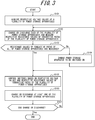
- FIG. 3 An example operation performed by the power control apparatus 20 serving as the control apparatus according to the embodiment of the present disclosure will be described with reference to FIG. 3 . Note that this operation is described to be started in a state in which all of the switches 14 of the plurality of power storage apparatuses 10 are OFF.
- Step S101 The controller 21 acquires the respective voltage values of the plurality of power storage apparatuses 10.
- the controller 21 may communicate with the power storage apparatuses 10 and acquire the respective voltage values measured by the respective voltmeters 15 of the power storage apparatuses 10.
- Step S102 The controller 21 discharges or charges each of the plurality of power storage apparatuses 10 and measures the respective resistance values of the conductive paths of the plurality of power storage apparatuses 10.
- the controller 21 may turn on the switch 14 of the power storage apparatus 10 having the largest voltage value, from among the plurality of power storage apparatuses 10.
- Step S103 The controller 21 determines whether the respective resistance values of the conductive paths of all of the power storage apparatuses 10 have been measured.
- Step S104 In a case in which the respective resistance values of the conductive paths of all of the power storage apparatuses 10 have not been measured (No at step S103), the controller 21 changes the power storage apparatus 10 in which the switch 14 is to be turned on. Then, the controller 21 repeats the process from step S102.
- Step S105 In a case in which the respective resistance values of the conductive paths of all of the power storage apparatuses 10 have been measured (Yes at step S103), the controller 21 controls the switch 14, based on the respective voltage values of the plurality of power storage apparatuses 10 and the respective resistance values of the conductive paths of the plurality of power storage apparatuses 10.
- Step S106 The controller 21 charges or discharges at least one of the plurality of power storage apparatuses 10 in a manner to not interrupt the charging or discharging by the plurality of power storage apparatuses 10.
- Step S107 The controller 21 determines whether to end charge or discharge by the plurality of power storage apparatuses 10. When the controller 21 determines to end charge or discharge by the plurality of power storage apparatuses 10 (Yes at step S107), the controller 21 ends this operation. When the controller 21 determines to continue charge or discharge by the plurality of power storage apparatuses 10 (No at step S107), the controller 21 repeats the process from step S105.
- the power control apparatus 20 may control the switch 14 in a manner to reduce the total loss due to the resistances of the conductive paths of the plurality of power storage apparatuses 10.
- the power control apparatus 20 calculates a combination of n-number of the power storage apparatuses 10 that substantially satisfies the equations (2) and (3), from among from the N-number of the power storage apparatuses 10 included in the power storage system 1.
- the power control apparatus 20 can evaluate the total loss due to the resistance of the conductive paths of the power storage apparatuses 10 included in all possible combinations of the n-numbers of the power storage apparatuses 10 and adopt a combination having the smallest total loss.
- the total loss due to the resistance of the conductive paths of the plurality of power storage apparatuses 10 may be expressed by the following equation (8): Ibat 1 2 R 1 + Ibat 2 2 R 2 + ⁇ + Ibat n 2 R n
- Ibat 1 to Ibat N are the respective current values of the N-number of the power storage apparatuses 10.
- R 1 to R N are the respective resistance values of the conductive paths of the N-number of the power storage apparatuses 10.
- the power control apparatus 20 may control the switch 14 in a state in which the n-number of the power storage apparatuses 10 included in the adopted combination of the power storage apparatuses 10 substantially satisfy the equations (2) and (3) and continue charge or discharge by the plurality of power storage apparatuses 10.
- the power control apparatus 20 may control the switch 14 such that the total loss due to the resistance of the conductive paths of the plurality of power storage apparatuses 10 becomes equal to or less than a predetermined threshold value.
- the power control apparatus 20 calculates a combination of n-number of the power storage apparatuses 10 that substantially satisfies the equations (2) and (3), from among the N-number of the power storage apparatuses 10 included in the power storage system 1.
- the power control apparatus 20 may set the predetermined threshold value in advance and sequentially evaluate the total loss due to the resistance of the conductive paths of the power storage apparatuses 10 included in the combination of the n-number of the power storage apparatuses 10, until the power control apparatus 20 finds a combination of the power storage apparatuses 10 having the total loss equal to or lower than the threshold value.
- the power control apparatus 20 finds the combination of the power storage apparatuses 10 in which the total loss due to the resistance of the conductive paths is equal to or less than the predetermined threshold value, the power control apparatus 20 may adopt the combination of the power storage apparatuses 10.
- the power control apparatus 20 may control the switch 14 in a state in which the n-number of the power storage apparatuses 10 included in the adopted combination of the power storage apparatuses 10 substantially satisfy the equations (2) and (3) and continue charge or discharge by the plurality of power storage apparatuses.
- the power storage system 1 includes the power storage apparatus 10A, 10B, 10C, and the power control apparatus 20, as illustrated in FIG. 1 .
- the power storage apparatus 10A, 10B, and 10C are connected in parallel to one another.
- the power control apparatus 20 operates as the control apparatus for the power storage apparatuses 10A, 10B, and 10C.
- the voltage value Vbat_10A of the power storage apparatus 10A, the voltage value Vbat_10B of the power storage apparatus 10B, and the voltage value Vbat_10C of the power storage apparatus 10C are respectively 200 V, 208 V, and 220 V, by way of example.
- the resistance value R_10A of the conductive path of the power storage apparatus 10A, the resistance value R_10B of the conductive path of the power storage apparatus 10B, and the resistance value R_10C of the conductive path of the power storage apparatus 10C are respectively 1 ⁇ , 3 ⁇ , and 6 ⁇ .
- the power control apparatus 20 receives an instruction to perform discharge such that the total current value of the power storage apparatuses 10A, 10B, and 10C becomes 12A.
- the power control apparatus 20 calculates a total loss due to the resistance of the conductive path of each of the combinations of the power storage apparatuses that satisfies the equations (2) and (3) when Ipcs is 12A, based on the respective voltage values of the power storage apparatus 10A, 10B, and 10C and the respective resistance values of the conductive paths of the power storage apparatus 10A, 10B, and 10C.
- the power control apparatus 20 may discharge all of the power storage apparatuses 10A, 10B, and 10C, by setting Vpcs to 196 V and setting Ibat_10A, Ibat_10B, and Ibat_10C to 4A.
- the power control apparatus 20 may discharge the power storage apparatuses 10A and 10C by setting Vpcs to 193 V, Ibat_10A to 7 A, and Ibat_10C to 4.5 A.
- the power control apparatus 20 may discharge the power storage apparatuses 10B and 10C by setting Vpcs to 190 V, Ibat_10B to 6 A, and Ibat_10C to 5 A.
- the power storage system 1 includes the plurality of power storage apparatuses 10 and a control apparatus constituted of the power control apparatus 20 or the like.
- the plurality of power storage apparatuses 10 are connected in parallel to one another via the switch 14.
- the control apparatus is configured to control the switch 14, based on the respective voltage values of the plurality of power storage apparatuses 10 and the respective resistance values of the conductive paths of the plurality of power storage apparatuses 10.
- the control apparatus charges or discharges at least one of the plurality of power storage apparatuses 10.
- the control apparatus having the above configuration selects the power storage apparatus 10 to charge or discharge, based on the voltage value of the power storage apparatus 10 and the resistance value of the conductive path of the power storage apparatus 10.
- the power storage system 1 can charge or discharge the plurality of power storage apparatuses 10 in consideration of characteristic differences between the power storage apparatuses 10 due to the difference in the distances of installation locations and the degree of aging deterioration, whereby the usefulness of the technique of connecting apparatuses in parallel to charge or discharge is improved. Further, the power storage system 1 takes the resistance value of the conductive path of the power storage apparatus 10 into consideration and thus can reduce the probability of occurrence of an inrush current, arc discharge, or the like when controlling the switch of the power storage apparatus 10.
- the power storage apparatus 10 in a case in which the power storage apparatus 10 is newly connected in parallel to another power storage apparatus 10 that is charging or discharging, based on the voltage value alone of the power storage apparatus 10 measured by the voltmeter or the like, even although the measured voltage value is approximately equal to that of another power storage apparatus, the power storage apparatus 10 that is newly connected may not immediately charge or discharge. In this case, bias charge by the power storage apparatus 10 that is charging or discharging occurs, inhibiting effective charge or discharge by the power storage apparatus 10 that is newly connected. According to the power storage system 1 of the present embodiment, a difference between the measured voltage value and the actual voltage value of the power storage apparatus 10 originating from the resistance value of the conductive path of the power storage apparatus 10 can be reduced. Thus, a predetermined current can be taken out from the power storage apparatus 10 that is newly connected in parallel, and this power storage apparatus 10 can be effectively used immediately after the connection.
- control apparatus such as the power control apparatus 20 included in the power storage system 1 according to the present embodiment is configured to control the switch 14 such that the power storage apparatus 10 having a small resistance value of the conductive path, from among the plurality of power storage apparatuses 10, preferentially charges or discharges.
- the power storage system 1 configured as described above can reduce the probability of occurrence of a loss due to the resistance of the conductive path of the power storage apparatus 10 caused by charge or discharge.
- the control apparatus such as the power control apparatus 20 included in the power storage system 1 according to the present embodiment controls the switch 14 such that the respective current values of the power storage apparatuses 10 to charge or discharge are substantially equal to one another. Since the power storage system 1 configured as described above can reduce the bias of the currents to be input or output to the plurality of power storage apparatuses 10, the probability to deteriorate a particular one of the power storage apparatuses is reduced.
- control apparatus such as the power control apparatus 20 included in the power storage system 1 according to the present embodiment is configured to control the switch 14 to reduce the total loss due to the resistance of the conductive paths of the plurality of power storage apparatuses 10.
- the power storage system 1 configured as described above can reduce the probability of occurrence of a loss due to the resistance of the conductive paths of the power storage apparatuses 10 caused by charge or discharge.
- the control apparatus such as the power control apparatus 20 included in the power storage system 1 according to the present embodiment is configured to control the switch 14 such that the total loss due to the resistance of the conductive paths of the plurality of power storage apparatuses 10 is equal to or less than the predetermined threshold value.
- the power storage system 1 configured as described above can end the evaluation at the point when a reasonable combination of the power storage apparatuses 10 is found before performing the evaluation of the loss during charging or discharging caused by all combinations of the power storage apparatuses 10. Thus, an amount to be calculated by the control apparatus and an amount of data to be stored can be reduced.
- control apparatus such as the power control apparatus 20 included in the power storage system 1 according to the present embodiment is configured to charge or discharge each of the plurality of power storage apparatuses 10 and measure the respective resistance values of the conductive paths of the plurality of power storage apparatuses 10. According to this configuration, the control apparatus selects the power storage apparatus 10 to charge or discharge, based on the voltage value of the power storage apparatus 10 and the resistance value of the conductive path of the power storage apparatus 10.
- the power storage system 1 can charge or discharge the plurality of power storage apparatuses 10 in consideration of the characteristic difference therebetween due to the difference in the distances of installation locations and the degree of aging deterioration, whereby the usefulness of the technique of connecting a plurality of apparatuses in parallel to charge or discharge is improved.
- the power control apparatus 20 has been described to operate as the control apparatus, this is not restrictive.
- the control apparatus may be provided separately from the power control apparatus 20.
- the control apparatus may be included in a battery management system for controlling and managing the plurality of power storage apparatuses 10.
- the control apparatus may be included in a home energy management system or the like.
- the control apparatus may be provided separately from the power control apparatus 20. In this case, a part or all of the operation that has been described above to be performed by the power control apparatus 20 may be realized by the control apparatus.
- the switches 14 may be provided separately from the plurality of power storage apparatuses 10.
- the control apparatus may be communicably connected to the switches 14.
- the power control apparatus 20 may store the respective resistance values of the conductive paths of the power storage apparatuses 10, in advance.
- the power control apparatus 20 may calculate or estimate the resistance value of the conductive path, based on some or all of the values.
- the power control apparatus 20 may perform the operation described above using the resistance value of the conductive path of the power storage apparatus 10 that has been stored in advance.
Landscapes
- Engineering & Computer Science (AREA)
- Power Engineering (AREA)
- Manufacturing & Machinery (AREA)
- Chemical & Material Sciences (AREA)
- Chemical Kinetics & Catalysis (AREA)
- Electrochemistry (AREA)
- General Chemical & Material Sciences (AREA)
- Charge And Discharge Circuits For Batteries Or The Like (AREA)
- Secondary Cells (AREA)
- Supply And Distribution Of Alternating Current (AREA)
Abstract
Description
- This application claims priority to and the benefit of
Japanese Patent Application No. 2018-203077 filed on October 29, 2018 - The present disclosure relates to a power storage system, a control apparatus for a power storage apparatus, and a control method.
- Conventionally, in a power storage system that includes a plurality of power storage apparatuses connected in parallel, a technique of charging or discharging the plurality of power storage apparatuses in consideration of a characteristic difference therebetween caused by aging deterioration or the like is known. For example, PTL1 set forth below discloses a power supply apparatus that includes a plurality of power storage modules and is configured to turn off a switch of a power storage module and cut off a current of the power storage module in which a current flows in a direction opposite to a normal direction or in which a current imbalance is larger than a preset value.
- PTL 1:
JP-A-2001-185228 - A power storage system according to an embodiment of the present disclosure includes a plurality of power storage apparatuses and a control apparatus. The plurality of power storage apparatuses are connected in parallel to each other via respective switches. The control apparatus controls the switches, based on respective voltage values of the plurality of power storage apparatuses and respective resistance values of conductive paths of the plurality of power storage apparatuses. The control apparatus charges or discharges at least one of the plurality of power storage apparatuses.
- A control apparatus according to an embodiment of the present disclosure is a control apparatus for a plurality of power storage apparatuses. The plurality of power storage apparatuses are connected in parallel to each other via respective switches. The control apparatus controls the switches, based on respective voltage values of the plurality of power storage apparatuses and respective resistance values of conductive paths of the plurality of power storage apparatuses. The control apparatus charges or discharges at least one of the plurality of power storage apparatuses.
- A control method according to an embodiment of the present disclosure is a control method for a plurality of power storage apparatuses. The plurality of power storage apparatuses are connected in parallel to each other via respective switches. The control method includes a step of controlling the switches, based on respective voltage values of the plurality of power storage apparatuses and respective resistance values of conductive paths of the plurality of power storage apparatuses. The control method includes a step of charging or discharging at least one of the plurality of power storage apparatuses.
- In the accompanying drawings:
-
FIG. 1 is a schematic configuration diagram illustrating a power storage system according to an embodiment of the present disclosure; -
FIG. 2 is a diagram illustrating a flow of an operation performed by the power storage system illustrated inFIG. 1 ; -
FIG. 3 is a flow chart illustrating an example operation performed by a power control apparatus illustrated inFIG. 1 ; and -
FIG. 4 is a diagram illustrating another example operation performed by the power control apparatus illustrated inFIG. 1 . - Hereinafter, a power storage system that improves the usefulness of a technique of charging or discharging a plurality of power storage apparatuses connected in parallel, a control apparatus for the power storage apparatuses, and a control method will be disclosed. According to the power storage system, the control apparatus for the power storage apparatuses, and the control method according to an embodiment of the present disclosure, the usefulness of the technique of charging or discharging the plurality of power storage apparatuses connected in parallel is improved.
-
FIG. 1 is a schematic configuration diagram illustrating an example of a power storage system 1 according to the embodiment of the present disclosure. The power storage system 1 may include apparatuses such as a plurality ofpower storage apparatuses power control apparatus 20. InFIG. 1 , the plurality ofpower storage apparatuses power control apparatus 20 viapower lines 40. Thepower control apparatus 20 is connected to apower grid 60. Thepower lines 40 are indicated by solid lines inFIG. 1 . The power storage system 1 selectively discharges electric power from thepower storage apparatus power grid 60, aload 70, and the like. Theload 70 is, for example, an electric apparatus such as a lighting or an air conditioner. Theload 70 is not limited thereto and may be any electric apparatus that consumes electric power. Further, the power storage system 1 selectively charges thepower storage apparatuses power grid 60. Hereinafter, when thepower storage apparatuses power storage apparatus 10, collectively. - In the power storage system 1, the apparatuses included in the power storage system 1 such as the plurality of
power storage apparatuses 10 and thepower control apparatus 20 are communicably connected to each other via acommunication line 50. Thecommunication line 50 is indicated by a dotted line inFIG. 1 . Thecommunication line 50 may be a wired line, a wireless line, or both. Although the power storage system 1 includes threepower storage apparatuses 10 and onepower control apparatus 20 inFIG. 1 by way of example, the number and configuration of the apparatuses included in the power storage system 1 can be appropriately determined according to requirements such as a charging capacity, a discharging capacity, or the like. - The
power storage apparatus 10 charges or discharges electric power. Thepower storage apparatus 10 may perform an operation including charging or discharging of electric power, based on the control by a control apparatus such as thepower control apparatus 20. Thepower storage apparatus 10 may include any storage battery such as, for example, a lead storage battery, a nickel hydrogen storage battery, a lithium ion battery, a sodium sulfur battery, or a combination thereof. - The
power control apparatus 20 is also referred to as a PCS (Power Conditioning System). Thepower control apparatus 20 is configured to convert DC power discharged from thepower storage apparatus 10 into AC power or convert AC power supplied from thepower grid 60 into DC power. Thepower control apparatus 20 may be used as a control apparatus for controlling charge and discharge of electric power by thepower storage apparatus 10. In this case, thepower control apparatus 20 may control charge and discharge of electric power by the plurality ofpower storage apparatuses 10, by turning on or off a switch of thepower storage apparatus 10, as will be described later. - When the electric power is charged or discharged by the
power storage apparatus 10, a portion of electric power to be charged or discharged is consumed by resistance of a conductive path of thepower storage apparatus 10, whereby a voltage drop occurs. The resistance of the conductive path of thepower storage apparatus 10 includes, for example, internal resistance of thepower storage apparatus 10, wiring resistance of thepower lines 40 connecting thepower storage apparatus 10 and thepower control apparatus 20, resistance of the switch included in thepower storage apparatus 10, and the like. The resistance of the conductive path of thepower storage apparatus 10 may have an impact on the control of the plurality ofpower storage apparatuses 10 included in the power storage system 1. For example, the resistance of the conductive path of thepower storage apparatus 10 varies depending on a distance of an installation location of thepower storage apparatus 10 from thepower control apparatus 20, a degree of aging deterioration, or the like and can cause a characteristic difference in each operation of thepower storage apparatus 10. Further, due to the voltage drop caused by the resistance of the conductive path of thepower storage apparatus 10, an error may occur between a voltage value of thepower storage apparatus 10 measured by a voltmeter or the like and an actual voltage value of thepower storage apparatus 10. As a result, when the switch of thepower storage apparatus 10 is controlled based on the measured voltage value, an unexpected inrush current, arc discharge, or the like may occur. - In the power storage system 1 according to the embodiment of the present disclosure, for example, the
power control apparatus 20 serving as the control apparatus is configured to control charge and discharge by the plurality ofpower storage apparatuses 10, based on respective voltage values of the plurality ofpower storage apparatuses 10 and respective resistance values of the conductive paths of the plurality ofpower storage apparatuses 10. Thus, the power storage system 1 can efficiently charge and discharge the plurality ofpower storage apparatuses 10, in consideration of the characteristic difference between thepower storage apparatuses 10 due to a difference in distances of installation locations, the degrees of aging deterioration, or the like. Thepower storage apparatus 10 and thepower control apparatus 20 included in the power storage system 1 will be described below. - Hereinafter, a schematic configuration of the
power storage apparatus 10 serving as an example of the power storage apparatus according to the embodiment of the present disclosure will be described. Thepower storage apparatus 10 includes a controller 11, apower storage unit 12, aterminal unit 13, aswitch 14, avoltmeter 15, anammeter 16, acommunication interface 17, and amemory 18, as illustrated inFIG. 1 . - The controller 11 includes one or more processors configured to provide control and processing ability for realizing each function of the
power storage apparatus 10. The controller 11 may include a processor such as a CPU (Central Processing Unit) configured to execute a program defining a control procedure or a dedicated processor specialized in processing each function. - The controller 11 is connected to each function of the
power storage apparatus 10 described above in a wired or wireless manner and configured to control and manage all or a part of thepower storage apparatus 10 including the functional units. The controller 11 is configured to acquire a program stored in thememory 18 and execute the program to realize various functions associated with each function of thepower storage apparatus 10. The control performed by the controller 11 characteristic of the present embodiment will be further described later. - The
power storage unit 12 charges and discharges electric power, based on the control by the controller 11. Thepower storage unit 12 may include any storage battery such as, for example, a lead storage battery, a nickel hydrogen storage battery, a lithium ion battery, a sodium sulfur battery, or a combination thereof. Thepower storage unit 12 may be composed of one or more cells. The charge and discharge of electric power by thepower storage unit 12 may be controlled and managed by the controller 11 in units of cells. Alternatively, charge and discharge of electric power by thepower storage unit 12 may be controlled and managed by the controller 11 in units of modules in which a plurality of cells are connected. The number of cells and modules constituting thepower storage unit 12 and the number of cells included in the module may be appropriately determined according to the application of thepower storage apparatus 10 or the like. - A
terminal unit 13 may include a positive electrode terminal and a negative electrode terminal. The positive electrode terminal and the negative electrode terminal are respectively represented by P and N inFIG. 1 . The positive electrode terminal of theterminal unit 13 of thepower storage apparatus 10A is connected to positive electrode terminals of the otherpower storage apparatuses 10B and 20C and thepower control apparatus 20 via apower line 40A. The negative electrode terminal of theterminal unit 13 of thepower storage apparatus 10A is connected to negative electrode terminals of the otherpower storage apparatuses 10B and 20C and thepower control apparatus 20 via thepower line 40B. In the power storage system 1, thus, thepower storage apparatuses - The
switch 14 conductively connects or disconnects theterminal unit 13 and thepower storage unit 12, based on the control by the controller 11. When theswitch 14 is turned on, thepower storage apparatus 10 may start charge or discharge by thepower storage unit 12. Also, when theswitch 14 is turned off, thepower storage apparatus 10 may stop charge or discharge by thepower storage unit 12. Theswitch 14 may include any switching element such as, for example, a transistor or a MOSFET. Although theswitch 14 is arranged between the positive electrode terminal of thepower storage unit 12 and the positive electrode terminal of theterminal unit 13 inFIG. 1 , this is not restrictive. Theswitch 14 may be arranged at any location where theswitch 14 can disconnect electric conduction between thepower storage apparatus 10 and thepower control apparatus 20. - The
voltmeter 15 measures a voltage value of thepower storage apparatus 10, based on the control by the controller 11. The voltage value of thepower storage apparatus 10 may be a value of a so-called open end voltage in a sate in which theswitch 14 is turned off. The voltage value of thepower storage apparatus 10 may be a value of a discharge voltage from thepower storage unit 12 during discharge by thepower storage apparatus 10 before the voltage drops due to resistance of the conductive path. The voltage value of thepower storage apparatus 10 may be a value of a charging voltage of thepower storage unit 12 during charging by thepower storage apparatus 10 after the voltage drops due to resistance of the conductive path. Thevoltmeter 15 may be any appropriate apparatus such as a voltmeter, a voltage sensor, or the like. Thevoltmeter 15 transmits a measured voltage value to the controller 11. Although thevoltmeter 15 is arranged between thepower storage unit 12 and theterminal unit 13 inFIG. 1 , this is not restrictive. Thevoltmeter 15 may be arranged at any location where thevoltmeter 15 can measure the voltage value of thepower storage apparatus 10. - The
ammeter 16 measures a current value of thepower storage apparatus 10, based on the control by the controller 11. Theammeter 16 may be any apparatus including an ammeter or a current sensor. Theammeter 16 transmits a measured voltage value to the controller 11. Although theammeter 16 is arranged between the positive electrode terminal of thepower storage unit 12 and the positive electrode terminal of theterminal unit 13 inFIG. 1 , this is not restrictive. Theammeter 16 may be arranged at any position where theammeter 16 can measure the current value of thepower storage apparatus 10. In the present disclosure, the current value of thepower storage apparatus 10 will be described, provided that a direction in which a current flows when thepower storage apparatus 10 discharges is defined as a positive direction. Thus, the current value of thepower storage apparatus 10 takes a positive value during discharge by thepower storage apparatus 10 and a negative value during charge by thepower storage apparatus 10. - The
communication interface 17 communicates with other apparatuses included in the power storage system 1, based on the control by the controller 11. Thecommunication interface 17 may include, for example, a CAN (Controller Area Network) communication module, a wired LAN (Local Area Network) communication module, a wireless LAN communication module, or the like. InFIG. 1 , thecommunication interface 17 of thepower storage apparatus 10A is connected to thecommunication line 50 together with thepower storage apparatus 10B and 10C included in the power storage system 1 and thepower control apparatus 20. As a result, thepower storage apparatus 10A can receive, for example, a control signal for controlling the power storage apparatus from another apparatus included in the power storage system 1 and operate based on the received control signal. The control signal includes, but is not limited to, an instruction for turning on or off the switch of the power storage apparatus, and an instruction for starting an operation such as charge or discharge by the power storage apparatus. To send and receive signals between the apparatuses connected to thecommunication line 50, the apparatuses including thepower storage apparatuses 10 that are connected to thecommunication line 50 may be provided with information such as respective IDs (identifiers) that uniquely identify the apparatuses during communication. - The
memory 18 includes, for example, a semiconductor memory, a magnetic memory, an optical memory, or the like. Thememory 18 may function as, for example, a main storage apparatus or an auxiliary storage apparatus. Thememory 18 may be a cache memory or the like of the processor included in the controller 11. Thememory 18 may be a volatile storage apparatus or a non-volatile storage apparatus. Thememory 18 stores information and programs used for control and processing for realizing each function of thepower storage apparatus 10. Thememory 18 may store information such as, for example, the IDs described above used for transmitting and receiving signals between apparatuses connected to thecommunication line 50. Further, thememory 18 may store conditions used for controlling the switch, which will be described later. - Hereinafter, a schematic configuration of the
power control apparatus 20 serving as an example of the power control apparatus according to the embodiment of the present disclosure will be described. Thepower control apparatus 20 includes acontroller 21, apower converter 22, aterminal unit 23, avoltmeter 24, anammeter 25, acommunication interface 26, amemory 27, anotification interface 28, aninput interface 29, and the like, as illustrated inFIG. 1 . - The
controller 21 includes one or more processors configured to provide control and processing ability for realizing each function of thepower control apparatus 20, as will be described in detail later. Thecontroller 21 may include a processor such as a CPU configured to execute a program defining a control procedure or a dedicated processor specialized in processing each function. - The
controller 21 is connected to each function of thepower control apparatus 20 described above in a wired or wireless manner and configured to control and manages all or a part of thepower control apparatus 20 including the functional units. Thecontroller 21 acquires a program stored in thememory 27 and executes the program, whereby thecontroller 21 realizes various functions associated with each function of thepower control apparatus 20. The control characteristic of the present embodiment performed by thecontroller 21 when thepower control apparatus 20 operates as a control apparatus for the plurality ofpower storage apparatuses 10 included in the power storage system 1 will be further described later. - The
power converter 22 converts DC power into AC power or converts AC power into DC power, based on the control by thecontroller 21. - The
terminal unit 23 may include a positive electrode terminal and a negative electrode terminal. InFIG. 1 , the positive electrode terminal of thepower control apparatus 20 is connected to respective positive electrode terminals of the plurality ofpower storage apparatuses 10 via thepower line 40A, and the negative electrode terminal of thepower control apparatus 20 is connected to respective negative electrode terminals of the plurality ofpower storage apparatuses 10 via thepower line 40B. - The
voltmeter 24 measures the voltage value of thepower control apparatus 20, based on the control by thecontroller 21. Thevoltmeter 24 may be any apparatus including a voltmeter or a voltage sensor. A measured voltage value of thepower control apparatus 20 may be used as a voltage value of charge or discharge by at least one of thepower storage apparatuses 10 that includes theswitch 14 being turned on and also is connected to thepower control apparatus 20. In the present disclosure, the voltage value of thepower control apparatus 20 is also referred to as a voltage value of charge or discharge by the plurality ofpower storage apparatuses 10. Thevoltmeter 24 transmits the measured voltage value to thecontroller 21. InFIG. 1 , thevoltmeter 24 is arranged between thepower converter 22 and theterminal unit 23. However, thevoltmeter 24 is not limited thereto and may be arranged at any position where thevoltmeter 24 can measure the voltage value of charge or discharge by the plurality ofpower storage apparatuses 10. - The
ammeter 25 measures the current value of thepower control apparatus 20, based on the control by thecontroller 21. Theammeter 25 may be any apparatus including an ammeter or a current sensor. A measured current value of thepower control apparatus 20 may be used as a total current value of charging or discharging by at least one of thepower storage apparatuses 10 that includes theswitch 14 being turned on and also is connected to thepower control apparatus 20, from among the plurality of power storage apparatuses. In the present disclosure, the current value of thepower control apparatus 20 will also be referred to as the total current value of charging or discharging by the plurality ofpower storage apparatuses 10. Theammeter 25 transmits the measured current value to thecontroller 21. InFIG. 1 , theammeter 25 is arranged between the positive electrode terminal of thepower converter 22 and the positive electrode terminal of theterminal unit 23. However, theammeter 25 is not limited thereto and may be arranged at any position where theammeter 25 can measure the total current value of charging or discharging by the plurality ofpower storage apparatuses 10. Note that in the present disclosure the current value of thepower control apparatus 20 will be described, provided that the direction in which the current flows when thepower storage apparatus 10 discharges is defined as the positive direction. Thus, the current value of thepower control apparatus 20 takes a positive value when thepower storage apparatus 10 discharges and a negative value when thepower storage apparatus 10 charges electric power. - The
communication interface 26 communicates with other apparatus included in the power storage system 1, based on the control by thecontroller 21. Thecommunication interface 26 may include, for example, a CAN communication module, a wired LAN communication module, a wireless LAN communication module, or the like. InFIG. 1 , thecommunication interface 26 of thepower control apparatus 20 is connected to thecommunication line 50 together with the plurality ofpower storage apparatuses 10 included in the power storage system 1. As a result, thepower control apparatus 20 can transmit, for example, control signals for controlling the power storage apparatuses to the plurality ofpower storage apparatuses 10 included in the power storage system 1. The control signal includes, but is not limited to, an instruction for turning on or off the switch of the power storage apparatus, and an instruction for starting an operation such as charge or discharge by the power storage apparatus. - The
memory 27 includes, for example, a semiconductor memory, a magnetic memory, an optical memory, or the like. Thememory 27 may function as, for example, a main storage apparatus or an auxiliary storage apparatus. Thememory 27 may be a cache memory or the like of the processor included in the controller 11. Further, thememory 27 may be a volatile storage apparatus or a non-volatile storage apparatus. Thememory 27 stores the information and programs used for control and processing for realizing each function of thepower storage apparatus 10. Thememory 27 may store information such as, for example, the IDs for uniquely identifying thepower storage apparatuses 10 included in the power storage system 1. Further, thememory 27 may store conditions used for controlling the plurality ofpower storage apparatuses 10 included in the power storage system 1, which will be described later. - The
notification interface 28 notifies information by sound, a vibration, light, an image, or the like, based on the control by thecontroller 21. Thenotification interface 28 includes at least one of a speaker, an oscillator, a lamp, and a display apparatus. Thenotification interface 28 may notify information such as an on-state or an off-state of theswitch 14 of thepower storage apparatus 10, the voltage value of thepower storage apparatus 10, and the resistance value of the conductive path of thepower storage apparatus 10. - The
input interface 29 receives an input operation from a user. Theinput interface 29 may include at least one of a mechanical key such as a power button, an input apparatus such as a touch panel, and a pointing device such as a mouse. When theinput interface 29 detects the input operation performed by the user, theinput interface 29 transmits the input operation as electronic information to thecontroller 21. The input operation may include, for example, an instruction to start charge or discharge by the plurality ofpower storage apparatuses 10, or an instruction to end charge or discharge by the plurality ofpower storage apparatuses 10. At least one of thenotification interface 28 and theinput interface 29 may be provided on, for example, a remote controller that is physically separated from thepower control apparatus 20. - Hereinafter, an operation performed by the
power control apparatus 20 when thepower control apparatus 20 operates as a control apparatus for the plurality ofpower storage apparatuses 10 included in the power storage system 1 will be described. - The
power control apparatus 20 acquires respective voltage values of the plurality ofpower storage apparatuses 10. Thepower control apparatus 20 may acquire the voltage value by, for example, communicating with each of the plurality ofpower storage apparatuses 10. In particular, thepower control apparatus 20 may transmit a signal requesting transmission of a voltage value to each of thepower storage apparatuses 10. Upon receiving the signal, thepower storage apparatus 10 may transmit a signal including the voltage value measured by thevoltmeter 15 of thepower storage apparatus 10 to thepower control apparatus 20. Thepower control apparatus 20 may store the voltage value included in the signal received from thepower storage apparatus 10 as the voltage value of thepower storage apparatus 10. - The
power control apparatus 20 is not limited to the method described above and may acquire the respective voltage values of the plurality ofpower storage apparatuses 10 by any appropriate method. For example, thepower control apparatus 20 may acquire the respective voltage values of the plurality ofpower storage apparatuses 10 from a battery management system (BMS) or a home energy management system (HEMS), which are configured to manage the plurality ofpower storage apparatuses 10. - The
power control apparatus 20 acquires respective resistance values of the conductive paths of the plurality ofpower storage apparatuses 10. Thepower control apparatus 20 may measure the respective resistance values of the conductive paths of the plurality ofpower storage apparatuses 10 by causing charge or discharge by each of the plurality ofpower storage apparatuses 10. In particular, thepower control apparatus 20 turns on theswitch 14 of any one of the plurality ofpower storage apparatuses 10 to cause thepower storage apparatus 10 to charge or discharge. Thepower control apparatus 20 measures a current value of thepower storage apparatus 10 in which theswitch 14 is turned on while thepower storage apparatus 10 is charging or discharging, and also measures the voltage value of thepower control apparatus 20. For example, thepower control apparatus 20 may communicate with thepower storage apparatus 10 in which theswitch 14 is turned on and thus acquire the current value measured by theammeter 16 of thepower storage apparatus 10. Further, thepower control apparatus 20 may measure the voltage value of thepower control apparatus 20 using thevoltmeter 24. - The
power control apparatus 20 can calculate the resistance value of the conductive path of thepower storage apparatus 10, using the measured voltage value of thepower storage apparatus 10, the current value of thepower storage apparatus 10, and the voltage value of thepower control apparatus 20, based on the following equation (1):
power storage apparatus 10, and Vbat is the voltage value of thepower storage apparatus 10. Ibat is the current value of thepower storage apparatus 10, and Vpcs is the voltage value of thepower control apparatus 20, i.e., the voltage value of charge or discharge by the plurality ofpower storage apparatuses 10. - After completion of the measurement of the resistance value of the conductive path of the
power storage apparatus 10 in which theswitch 14 is turned on, thepower control apparatus 20 changes thepower storage apparatus 10 in which theswitch 14 is to be turned on, to apower storage apparatus 10 having the resistance value of the conductive path that has not been measured. When changing to thepower storage apparatus 10 in which theswitch 14 is to be turned on, the discharge or charge by the power storage system 1 may be interrupted. Thus, when a predetermined condition is satisfied, such as during nighttime or when theload 70 is receiving electric power from thepower grid 60, thepower control apparatus 20 may change thepower storage apparatus 10 in which theswitch 14 is to be turned on. As a result, a risk of affecting the operation of theload 70 or the like by measuring the resistance value of the conductive path can be reduced. - The
power control apparatus 20 may repeat the above operation for all of the plurality ofpower storage apparatuses 10, until the measurement of the respective resistance values of the conductive paths of thepower storage apparatuses 10 is completed. Thepower control apparatus 20 may store the respective resistance values of the conductive paths calculated by controlling thepower storage apparatuses 10 as the respective resistance values of the conductive paths of thepower storage apparatuses 10. - An order of the
power storage apparatuses 10 to measure the resistance values of the conductive paths may be determined by thepower control apparatus 20 in any manner. For example, thepower control apparatus 20 may sequentially measure the resistance value from the largest voltage value of thepower storage apparatus 10. As a result, the possibly to affect the operation of theload 70 or the like due to a situation in which one of thepower storage apparatuses 10 falls out of charge while discharging electric power for the measurement of the resistance value of the conductive path can be reduced. - The
power control apparatus 20 may measure the resistance values of the conductive paths of thepower storage apparatuses 10 at predetermined timings. Wiring resistance and internal resistance vary depending on ambient temperature, aging deterioration, and the like. Thus, thepower control apparatus 20 may measure the resistance values of the conductive paths of thepower storage apparatuses 10 at predetermined intervals, or when the ambient temperature changes by a predetermined amount or more, and update the information stored in thememory 27. Alternatively, when a newpower storage apparatus 10 is installed as a replacement or as an addition, thepower control apparatus 20 may measure a resistance value of a conductive path of the newpower storage apparatus 10 and store the resistance value in thememory 27. - Hereinafter, an operation performed by the
power control apparatus 20 serving as the control apparatus to cause charge or discharge by the plurality ofpower storage apparatuses 10, based on the respective voltage values of the plurality ofpower storage apparatuses 10 and the respective resistance values of conductive paths of the plurality ofpower storage apparatuses 10 acquired in the above manner will be described. - The
power control apparatus 20 causes charge or discharge by at least onepower storage apparatus 10, from among the plurality ofpower storage apparatuses 10. Thepower control apparatus 20 may cause charge or discharge by at least onepower storage apparatus 10, from among the plurality ofpower storage apparatuses 10, by, for example, controlling theswitch 14 such that the current value of thepower control apparatus 20 becomes constant. - The
power control apparatus 20 may control theswitch 14 to cause charge or discharge by at least onepower storage apparatus 10, from among the plurality ofpower storage apparatuses 10, in a manner to not interrupt charge or discharge by the plurality ofpower storage apparatuses 10. - The
power control apparatus 20 may control theswitch 14 to preferentially charge or discharge thepower storage apparatus 10 having a smaller resistance value of the conductive path, from among the plurality ofpower storage apparatuses 10. For example, when thepower control apparatus 20 starts charge or discharge by the plurality ofpower storage apparatuses 10, thepower control apparatus 20 may turn on theswitch 14 of thepower storage apparatus 10 having the smallest resistance value of the conductive path, from among the plurality ofpower storage apparatuses 10. - The
power control apparatus 20 controls theswitch 14, based on the respective voltage values of the plurality ofpower storage apparatuses 10 and the respective resistance values of the conductive paths of the plurality ofpower storage apparatuses 10. In particular, when the power storage system 1 includes N-number (N is any integer) of thepower storage apparatuses 10, thepower control apparatus 20 may calculate a combination of n-number of thepower storage apparatuses 10 that substantially satisfies the following equations (2) and (3):

power storage apparatuses 10, and Ibati to Ibatn are respective current values of the n-number of thepower storage apparatuses 10. R1 to Rn are respective resistance values of the conductive paths of the n-number of thepower storage apparatuses 10, and Vpcs is the voltage value of thepower control apparatus 20, i.e., the voltage value of charge or discharge by the plurality ofpower storage apparatuses 10. Ipcs is the current value of thepower control apparatus 20, i.e., the total current value of charge or discharge by the plurality ofpower storage apparatuses 10. In the present disclosure, the combination of thepower storage apparatuses 10 includes at least onepower storage apparatus 10 selected from the plurality ofpower storage apparatuses 10. - In the present disclosure, "substantially satisfying" an equation is not limited to strictly satisfying the equation but means to satisfy the equation within a predetermined error range, without affecting the operations of the power storage system 1, the
power storage apparatus 10, and thepower control apparatus 20. Similarly, "substantially equal" to a value is not limited to be exactly equal to the value but means to be equivalent to the value within a predetermined error range, without affecting the operations of the power storage system 1, thepower storage apparatus 10, and thepower control apparatus 20. - The
power control apparatus 20 controls theswitch 14 in a state in which the n-number of thepower storage apparatuses 10 included in the calculated combination of thepower storage apparatuses 10 substantially satisfies the equations (2) and (3). For example, thepower control apparatus 20 may turn on theswitch 14 of at least one of thepower storage apparatuses 10, from among the n-number of thepower storage apparatus 10 in which theswitch 14 is OFF, to start charge or discharge, in a state in which the n-number of thepower storage apparatuses 10 substantially satisfy the equations (2) and (3). Further, for example, thepower control apparatus 20 may turn off theswitch 14 of at least one of thepower storage apparatuses 10, from among the n-number of thepower storage apparatuses 10 in which theswitch 14 is ON, to start charge or discharge, in a state in which the n-number of thepower storage apparatuses 10 substantially satisfy the equations (2) and (3). - The
power control apparatus 20 may calculate the combination of thepower storage apparatuses 10 that substantially satisfies the equations (2) and (3) described above at a predetermined timing during charge or discharge by the plurality ofpower storage apparatuses 10. The predetermined timing may be predetermined intervals. Alternatively, the predetermined timing may be a timing at which the voltage value of thepower control apparatus 20 or the current value of thepower control apparatus 20 changes. Thepower control apparatus 20 controls theswitch 14 in a state in which thepower storage apparatus 10 included in the calculated combination of thepower storage apparatuses 10 substantially satisfies the equations (2) and (3). Thus, thepower control apparatus 20 may charge or discharge at least one of thepower storage apparatuses 10, from among the plurality ofpower storage apparatuses 10, in a manner to not interrupt charge or discharge by the plurality ofpower storage apparatuses 10. - Further, for example, the
power control apparatus 20 may control theswitch 14 such that the current values of thepower storage apparatuses 10 to be charged and discharged are substantially equal to each other. In particular, thepower control apparatus 20 may calculate a combination of n-number of thepower storage apparatuses 10 that substantially satisfies an equation (4) set forth below, in addition to the equations (2) and (3) set forth above, from among the N-number of thepower storage apparatuses 10 included in the power storage system 1.
power storage apparatuses 10. - The
power control apparatus 20 controls theswitch 14 in a state in which the n-number of thepower storage apparatuses 10 included in the calculated combination of thepower storage apparatuses 10 substantially satisfy the equations (2), (3) and (4). For example, in the state in which the n-number of thepower storage apparatuses 10 substantially satisfy the equations (2), (3) and (4), thepower control apparatus 20 may turn on theswitch 14 of at least one of the n-number of thepower storage apparatuses 10 which is OFF, to start charge or discharge. For example, in the state in which the n-number of thepower storage apparatuses 10 substantially satisfy the equations (2), (3) and (4), thepower control apparatus 20 may turn off theswitch 14 of at least one of the n-number of thepower storage apparatuses 10 which is ON, to stop charge or discharge. - The
power control apparatus 20 may control theswitch 14 to cause charge or discharge by at least one of the plurality ofpower storage apparatuses 10, based on the respective voltage values of the plurality ofpower storage apparatuses 10 and the respective resistance values of the conductive paths of the plurality ofpower storage apparatuses 10, such that charge or discharge by the plurality ofpower storage apparatuses 10 are not interrupted and, simultaneously, all the current values of the plurality ofpower storage apparatuses 10 become substantially equal to each other. In particular, thepower control apparatus 20 may control theswitch 14 such that all of the N-number of thepower storage apparatuses 10 included in the power storage system 1 substantially satisfy equations (5), (6), and (7) set forth below. Thepower control apparatus 20 may repeatedly control theswitch 14 in a state in which n-number of thepower storage apparatuses 10, from among the N-number of thepower storage apparatuses 10, substantially satisfy the equations (2), (3), and (4), until all of the N-number of thepower storage apparatuses 10 substantially satisfy the equations (5), (6), and (7).


power storage apparatuses 10. Ibat1 to IbatN are respective current values of the N-number of thepower storage apparatuses 10, and R1 to RN are respective resistance values of the conductive paths of the N-number of thepower storage apparatuses 10. Vpcs is the voltage value of thepower control apparatus 20, i.e., the voltage value of charge or discharge by the plurality ofpower storage apparatuses 10, and Ipcs is the current value of thepower control apparatus 20, that is, the total current value of charge or discharge by the plurality ofpower storage apparatuses 10. - Hereinafter, an example of control of the
power storage apparatus 10 executed by the power storage system 1 according to the embodiment of the present disclosure will be described. The power storage system 1 includes thepower storage apparatuses power control apparatus 20, as illustrated inFIG. 1 . Thepower storage apparatuses power control apparatus 20 operates as a control apparatus for thepower storage apparatuses - The
power control apparatus 20 acquires respective voltage values of thepower storage apparatuses power storage apparatuses power control apparatus 20 communicates with thepower storage apparatuses power storage apparatus 10A, a voltage value Vbat_10B of thepower storage apparatus 10B, and a voltage value Vbat_10C of the power storage apparatus 10C are respectively 200 V, 208 V, and 220 V, by way of example. Thepower control apparatus 20 charges or discharges one of thepower storage apparatuses power storage apparatus 10. It is assumed that, as a result of the measurement, a resistance value R_10A of the conductive path of thepower storage apparatus 10A, a resistance value R_10B of the conductive path of thepower storage apparatus 10B, and a resistance value R_10C of the conductive path of the power storage apparatus 10C are respectively 1 Ω, 3 Ω, and 6 Ω, by way of example. - A flow of control performed by the
power control apparatus 20 for discharge by the plurality ofpower storage apparatuses power storage apparatuses power storage apparatuses FIG. 2. FIG. 2 illustrates the respective on/off states of theswitches 14 of thepower storage apparatuses voltmeter 15, the respective values of theammeter 16, the values of thevoltmeter 24 of thepower control apparatus 20, and the values of theammeter 25, at a plurality of different time points. It is assumed that thepower storage apparatuses - It is assumed that at a time T1 the
power control apparatus 20 receives an instruction to discharge thepower storage apparatus power control apparatus 20 turns on thepower storage apparatus 10A having the smallest resistance value of the conductive path, from among thepower storage apparatuses power storage apparatus 10A discharges at the current value of 15 A after the time point T1. - When the discharge by the
power storage apparatus 10A proceeds and the voltage of thepower storage apparatus 10A drops to 193 V at a time point T2, thepower control apparatus 20 determines that thepower storage apparatus 10A and thepower storage apparatus 10B substantially satisfy the equations (2), (3), and (4) set forth above. As a result, thepower control apparatus 20 determines that thepower storage apparatus 10B can be switched on. Thepower control apparatus 20 switches on thepower storage apparatus 10B at the time point T2. As a result, thepower storage apparatuses - The
power control apparatus 20 discharges thepower storage apparatus 10A and thepower storage apparatus 10B and, by a time point T3, the voltage of thepower storage apparatus 10A drops from the 193 V set forth above to 185 V. Similarly, the voltage of thepower storage apparatus 10B drops from 208 V to 200 V. Thepower control apparatus 20 switches off thepower storage apparatus 10A at the time point T3. As a result, thepower storage apparatus 10B discharges at the current value of 15 A after the time point T3. - When the discharge by the
power storage apparatus 10B progresses and the voltage of thepower storage apparatus 10B reaches 197.5 V at a time point T4, thepower control apparatus 20 determines that thepower storage apparatuses 10B and 10C satisfy the equations (2), (3), and (4) set forth above and that the storage apparatus 10C can be switched on. Thepower control apparatus 20 switches on the power storage apparatus 10C at the time point T4. As a result, thepower storage apparatus 10B and 10C discharge at the respective current values of 7.5 A after the time point T4. - The
power control apparatus 20 discharges thepower storage apparatuses 10B and 10C, whereby the voltage of thepower storage apparatus 10B drops from 197.5 V set forth above to 195 V by a time point T5. Similarly, the voltage of the power storage apparatus 10C drops from 220 V to 217.5 V. Thepower control apparatus 20 switches off thepower storage apparatus 10B at the time point T5. As a result, the power storage apparatus 10C discharges at the current value of 15 A after the time point T5. - The
power control apparatus 20 discharges the power storage apparatus 10C and, when the voltage of the power storage apparatus 10C reaches 210 V set forth above at a time point T6, determines that thepower storage apparatuses power control apparatus 20 determines that thepower storage apparatuses power control apparatus 20 switches on thepower storage apparatuses power storage apparatuses power control apparatus 20 may control thepower storage apparatuses power storage apparatus - An example operation performed by the
power control apparatus 20 serving as the control apparatus according to the embodiment of the present disclosure will be described with reference toFIG. 3 . Note that this operation is described to be started in a state in which all of theswitches 14 of the plurality ofpower storage apparatuses 10 are OFF. - Step S101: The
controller 21 acquires the respective voltage values of the plurality ofpower storage apparatuses 10. Thecontroller 21 may communicate with thepower storage apparatuses 10 and acquire the respective voltage values measured by therespective voltmeters 15 of thepower storage apparatuses 10. - Step S102: The
controller 21 discharges or charges each of the plurality ofpower storage apparatuses 10 and measures the respective resistance values of the conductive paths of the plurality ofpower storage apparatuses 10. Thecontroller 21 may turn on theswitch 14 of thepower storage apparatus 10 having the largest voltage value, from among the plurality ofpower storage apparatuses 10. - Step S103: The
controller 21 determines whether the respective resistance values of the conductive paths of all of thepower storage apparatuses 10 have been measured. - Step S104: In a case in which the respective resistance values of the conductive paths of all of the
power storage apparatuses 10 have not been measured (No at step S103), thecontroller 21 changes thepower storage apparatus 10 in which theswitch 14 is to be turned on. Then, thecontroller 21 repeats the process from step S102. - Step S105: In a case in which the respective resistance values of the conductive paths of all of the
power storage apparatuses 10 have been measured (Yes at step S103), thecontroller 21 controls theswitch 14, based on the respective voltage values of the plurality ofpower storage apparatuses 10 and the respective resistance values of the conductive paths of the plurality ofpower storage apparatuses 10. - Step S106: The
controller 21 charges or discharges at least one of the plurality ofpower storage apparatuses 10 in a manner to not interrupt the charging or discharging by the plurality ofpower storage apparatuses 10. - Step S107: The
controller 21 determines whether to end charge or discharge by the plurality ofpower storage apparatuses 10. When thecontroller 21 determines to end charge or discharge by the plurality of power storage apparatuses 10 (Yes at step S107), thecontroller 21 ends this operation. When thecontroller 21 determines to continue charge or discharge by the plurality of power storage apparatuses 10 (No at step S107), thecontroller 21 repeats the process from step S105. - Hereinafter, another example operation performed by the
power control apparatus 20 to charge or discharge the plurality ofpower storage apparatuses 10, based on the respective voltage values of the plurality ofpower storage apparatuses 10 and the respective resistance values of the conductive paths of the plurality ofpower storage apparatuses 10 will be described. - For example, the
power control apparatus 20 may control theswitch 14 in a manner to reduce the total loss due to the resistances of the conductive paths of the plurality ofpower storage apparatuses 10. Thepower control apparatus 20 calculates a combination of n-number of thepower storage apparatuses 10 that substantially satisfies the equations (2) and (3), from among from the N-number of thepower storage apparatuses 10 included in the power storage system 1. At this time, thepower control apparatus 20 can evaluate the total loss due to the resistance of the conductive paths of thepower storage apparatuses 10 included in all possible combinations of the n-numbers of thepower storage apparatuses 10 and adopt a combination having the smallest total loss. The total loss due to the resistance of the conductive paths of the plurality ofpower storage apparatuses 10 may be expressed by the following equation (8):
power storage apparatuses 10. R1 to RN are the respective resistance values of the conductive paths of the N-number of thepower storage apparatuses 10. Thepower control apparatus 20 may control theswitch 14 in a state in which the n-number of thepower storage apparatuses 10 included in the adopted combination of thepower storage apparatuses 10 substantially satisfy the equations (2) and (3) and continue charge or discharge by the plurality ofpower storage apparatuses 10. - Further, for example, the
power control apparatus 20 may control theswitch 14 such that the total loss due to the resistance of the conductive paths of the plurality ofpower storage apparatuses 10 becomes equal to or less than a predetermined threshold value. Thepower control apparatus 20 calculates a combination of n-number of thepower storage apparatuses 10 that substantially satisfies the equations (2) and (3), from among the N-number of thepower storage apparatuses 10 included in the power storage system 1. At this time, thepower control apparatus 20 may set the predetermined threshold value in advance and sequentially evaluate the total loss due to the resistance of the conductive paths of thepower storage apparatuses 10 included in the combination of the n-number of thepower storage apparatuses 10, until thepower control apparatus 20 finds a combination of thepower storage apparatuses 10 having the total loss equal to or lower than the threshold value. When thepower control apparatus 20 finds the combination of thepower storage apparatuses 10 in which the total loss due to the resistance of the conductive paths is equal to or less than the predetermined threshold value, thepower control apparatus 20 may adopt the combination of thepower storage apparatuses 10. Thepower control apparatus 20 may control theswitch 14 in a state in which the n-number of thepower storage apparatuses 10 included in the adopted combination of thepower storage apparatuses 10 substantially satisfy the equations (2) and (3) and continue charge or discharge by the plurality of power storage apparatuses. - Hereinafter, an example control of the
power storage apparatus 10 performed by thepower control apparatus 20 will be described with reference toFIG. 1 andFIG. 4 . The power storage system 1 includes thepower storage apparatus power control apparatus 20, as illustrated inFIG. 1 . Thepower storage apparatus power control apparatus 20 operates as the control apparatus for thepower storage apparatuses - As illustrated in
FIG. 4 , it is assumed that, as a result of acquiring the respective voltage values of thepower storage apparatuses power storage apparatuses power control apparatus 20, the voltage value Vbat_10A of thepower storage apparatus 10A, the voltage value Vbat_10B of thepower storage apparatus 10B, and the voltage value Vbat_10C of the power storage apparatus 10C are respectively 200 V, 208 V, and 220 V, by way of example. Further, it is also assumed that the resistance value R_10A of the conductive path of thepower storage apparatus 10A, the resistance value R_10B of the conductive path of thepower storage apparatus 10B, and the resistance value R_10C of the conductive path of the power storage apparatus 10C are respectively 1 Ω, 3 Ω, and 6 Ω. - It is assumed that the
power control apparatus 20 receives an instruction to perform discharge such that the total current value of thepower storage apparatuses power control apparatus 20 calculates a total loss due to the resistance of the conductive path of each of the combinations of the power storage apparatuses that satisfies the equations (2) and (3) when Ipcs is 12A, based on the respective voltage values of thepower storage apparatus power storage apparatus power control apparatus 20 may discharge all of thepower storage apparatuses power control apparatus 20 receives an instruction to discharge such that the total current value of thepower storage apparatuses power control apparatus 20 may discharge thepower storage apparatuses 10A and 10C by setting Vpcs to 193 V, Ibat_10A to 7 A, and Ibat_10C to 4.5 A. Further, in a case in which thepower control apparatus 20 receives an instruction to discharge such that the total current value of thepower storage apparatuses power control apparatus 20 may discharge thepower storage apparatuses 10B and 10C by setting Vpcs to 190 V, Ibat_10B to 6 A, and Ibat_10C to 5 A. - As described above, the power storage system 1 according to the present embodiment includes the plurality of
power storage apparatuses 10 and a control apparatus constituted of thepower control apparatus 20 or the like. The plurality ofpower storage apparatuses 10 are connected in parallel to one another via theswitch 14. The control apparatus is configured to control theswitch 14, based on the respective voltage values of the plurality ofpower storage apparatuses 10 and the respective resistance values of the conductive paths of the plurality ofpower storage apparatuses 10. The control apparatus charges or discharges at least one of the plurality ofpower storage apparatuses 10. The control apparatus having the above configuration selects thepower storage apparatus 10 to charge or discharge, based on the voltage value of thepower storage apparatus 10 and the resistance value of the conductive path of thepower storage apparatus 10. As a result, the power storage system 1 can charge or discharge the plurality ofpower storage apparatuses 10 in consideration of characteristic differences between thepower storage apparatuses 10 due to the difference in the distances of installation locations and the degree of aging deterioration, whereby the usefulness of the technique of connecting apparatuses in parallel to charge or discharge is improved. Further, the power storage system 1 takes the resistance value of the conductive path of thepower storage apparatus 10 into consideration and thus can reduce the probability of occurrence of an inrush current, arc discharge, or the like when controlling the switch of thepower storage apparatus 10. - Further, in a case in which the
power storage apparatus 10 is newly connected in parallel to anotherpower storage apparatus 10 that is charging or discharging, based on the voltage value alone of thepower storage apparatus 10 measured by the voltmeter or the like, even although the measured voltage value is approximately equal to that of another power storage apparatus, thepower storage apparatus 10 that is newly connected may not immediately charge or discharge. In this case, bias charge by thepower storage apparatus 10 that is charging or discharging occurs, inhibiting effective charge or discharge by thepower storage apparatus 10 that is newly connected. According to the power storage system 1 of the present embodiment, a difference between the measured voltage value and the actual voltage value of thepower storage apparatus 10 originating from the resistance value of the conductive path of thepower storage apparatus 10 can be reduced. Thus, a predetermined current can be taken out from thepower storage apparatus 10 that is newly connected in parallel, and thispower storage apparatus 10 can be effectively used immediately after the connection. - As described above, the control apparatus such as the
power control apparatus 20 included in the power storage system 1 according to the present embodiment is configured to control theswitch 14 such that thepower storage apparatus 10 having a small resistance value of the conductive path, from among the plurality ofpower storage apparatuses 10, preferentially charges or discharges. The power storage system 1 configured as described above can reduce the probability of occurrence of a loss due to the resistance of the conductive path of thepower storage apparatus 10 caused by charge or discharge. - As described above, the control apparatus such as the
power control apparatus 20 included in the power storage system 1 according to the present embodiment controls theswitch 14 such that the respective current values of thepower storage apparatuses 10 to charge or discharge are substantially equal to one another. Since the power storage system 1 configured as described above can reduce the bias of the currents to be input or output to the plurality ofpower storage apparatuses 10, the probability to deteriorate a particular one of the power storage apparatuses is reduced. - As described above, the control apparatus such as the
power control apparatus 20 included in the power storage system 1 according to the present embodiment is configured to control theswitch 14 to reduce the total loss due to the resistance of the conductive paths of the plurality ofpower storage apparatuses 10. The power storage system 1 configured as described above can reduce the probability of occurrence of a loss due to the resistance of the conductive paths of thepower storage apparatuses 10 caused by charge or discharge. - As described above, the control apparatus such as the
power control apparatus 20 included in the power storage system 1 according to the present embodiment is configured to control theswitch 14 such that the total loss due to the resistance of the conductive paths of the plurality ofpower storage apparatuses 10 is equal to or less than the predetermined threshold value. The power storage system 1 configured as described above can end the evaluation at the point when a reasonable combination of thepower storage apparatuses 10 is found before performing the evaluation of the loss during charging or discharging caused by all combinations of thepower storage apparatuses 10. Thus, an amount to be calculated by the control apparatus and an amount of data to be stored can be reduced. - As described above, the control apparatus such as the
power control apparatus 20 included in the power storage system 1 according to the present embodiment is configured to charge or discharge each of the plurality ofpower storage apparatuses 10 and measure the respective resistance values of the conductive paths of the plurality ofpower storage apparatuses 10. According to this configuration, the control apparatus selects thepower storage apparatus 10 to charge or discharge, based on the voltage value of thepower storage apparatus 10 and the resistance value of the conductive path of thepower storage apparatus 10. As a result, the power storage system 1 can charge or discharge the plurality ofpower storage apparatuses 10 in consideration of the characteristic difference therebetween due to the difference in the distances of installation locations and the degree of aging deterioration, whereby the usefulness of the technique of connecting a plurality of apparatuses in parallel to charge or discharge is improved. - Although the above embodiments have been described as typical examples, it will be apparent to those skilled in the art that many modifications and substitutions can be implemented within the spirit and scope of the present disclosure. Accordingly, the present disclosure should not be construed as being limited by the aforementioned embodiments, and various modifications or changes can be implemented without departing from the scope of the claims. For example, the functions included in each of the means or steps may be rearranged avoiding a logical inconsistency, such that a plurality of means or steps are combined, or one means or step is subdivided.
- For example, although in the above embodiments the
power control apparatus 20 has been described to operate as the control apparatus, this is not restrictive. The control apparatus may be provided separately from thepower control apparatus 20. For example, the control apparatus may be included in a battery management system for controlling and managing the plurality ofpower storage apparatuses 10. Alternatively, the control apparatus may be included in a home energy management system or the like. The control apparatus may be provided separately from thepower control apparatus 20. In this case, a part or all of the operation that has been described above to be performed by thepower control apparatus 20 may be realized by the control apparatus. - Further, for example, although in the above embodiments an example in which the
power storage apparatuses 10 include therespective switches 14 is illustrated, this is not restrictive. For example, theswitches 14 may be provided separately from the plurality ofpower storage apparatuses 10. In this case, the control apparatus may be communicably connected to theswitches 14. - Further, for example, although in the above embodiments an example in which the
power control apparatus 20 calculates the respective resistance values of the conductive paths of the plurality of thepower storage apparatuses 10, based on the measured voltage values and current values of thepower storage apparatuses 10 is illustrated, this is not restrictive. For example, thepower control apparatus 20 may store the respective resistance values of the conductive paths of thepower storage apparatuses 10, in advance. In a case in which, for example, respective resistance of the elements such as thepower line 40 constituting the conductive path, thepower storage unit 12, theterminal unit 23, theterminal unit 13, theswitch 14, theammeter 16, theammeter 25, and thepower converter 22 are recorded or stored in advance, thepower control apparatus 20 may calculate or estimate the resistance value of the conductive path, based on some or all of the values. In a case in which the voltage value and the current value of thepower storage apparatus 10 have not been measured, thepower control apparatus 20 may perform the operation described above using the resistance value of the conductive path of thepower storage apparatus 10 that has been stored in advance. -
- 1
- power storage system
- 10
- power storage apparatus
- 11
- controller
- 12
- power storage unit
- 13
- terminal unit
- 14
- switch
- 15
- voltmeter
- 16
- ammeter
- 17
- communication interface
- 18
- memory
- 20
- power control apparatus
- 21
- controller
- 22
- power converter
- 23
- terminal unit
- 24
- voltmeter
- 25
- ammeter
- 26
- communication interface
- 27
- memory
- 28
- notification interface
- 29
- input interface
- 40
- power line
- 50
- communication line
- 60
- power grid
- 70
- load
Claims (8)
- A power storage system comprising:a plurality of power storage apparatuses connected in parallel to each other via respective switches; anda control apparatus,wherein the control apparatus is configured tocontrol the switches, based on respective voltage values of the plurality of power storage apparatuses and respective resistance values of conductive paths of the plurality of power storage apparatuses, andcharge or discharge at least one of the plurality of power storage apparatuses.
- The power storage system according to claim 1,
wherein the control apparatus is configured to control the switches to preferentially charge or discharge a power storage apparatus having a small resistance value of the conductive path, from among the plurality of power storage apparatuses. - The power storage system according to claim 1 or 2,
wherein the control apparatus is configured to control the switches, such that current values of the power storage apparatuses to charge or discharge are substantially equal to each other. - The power storage system according to claim 1,
wherein the control apparatus is configured to control the switches to reduce a total loss due to the respective resistance values of the conductive paths of the plurality of power storage apparatuses. - The power storage system according to claim 1,
wherein the control apparatus is configured to control the switches, such that a total loss due to the respective resistance values of the conductive paths of the plurality of power storage apparatuses becomes equal to or less than a predetermined threshold. - The power storage system according to claim 1,
wherein the control apparatus is configured to charge or discharge each of the plurality of power storage apparatuses and measure the respective resistance values of the conductive paths of the plurality of power storage apparatuses. - A control apparatus for a plurality of power storage apparatuses connected in parallel to each other via respective switches, the control apparatus configured to:control the switches, based on respective voltage values of the plurality of power storage apparatuses and respective resistance values of conductive paths of the plurality of power storage apparatuses; andcharge or discharge at least one of the plurality of power storage apparatuses.
- A control method for a plurality of power storage apparatuses connected in parallel to each other via respective switches, the control method comprising:controlling the switches, based on respective voltage values of the plurality of power storage apparatuses and respective resistance values of conductive paths of the plurality of power storage apparatuses; andcharging or discharging at least one of the plurality of power storage apparatuses.
Applications Claiming Priority (2)
| Application Number | Priority Date | Filing Date | Title |
|---|---|---|---|
| JP2018203077 | 2018-10-29 | ||
| PCT/JP2019/039392 WO2020090349A1 (en) | 2018-10-29 | 2019-10-04 | Power storage system, control device for power storage device, and control method |
Publications (2)
| Publication Number | Publication Date |
|---|---|
| EP3876387A1 true EP3876387A1 (en) | 2021-09-08 |
| EP3876387A4 EP3876387A4 (en) | 2022-08-10 |
Family
ID=70464058
Family Applications (1)
| Application Number | Title | Priority Date | Filing Date |
|---|---|---|---|
| EP19877703.9A Withdrawn EP3876387A4 (en) | 2018-10-29 | 2019-10-04 | ENERGY STORAGE SYSTEM, CONTROL DEVICE FOR ENERGY STORAGE DEVICE, AND CONTROL METHOD |
Country Status (4)
| Country | Link |
|---|---|
| US (1) | US12218532B2 (en) |
| EP (1) | EP3876387A4 (en) |
| JP (1) | JP7055895B2 (en) |
| WO (1) | WO2020090349A1 (en) |
Families Citing this family (2)
| Publication number | Priority date | Publication date | Assignee | Title |
|---|---|---|---|---|
| US12531410B2 (en) | 2021-11-03 | 2026-01-20 | Lg Energy Solution, Ltd. | Battery rack management apparatus and method for operating same |
| CN118202448A (en) * | 2021-11-12 | 2024-06-14 | 东京毅力科创株式会社 | Substrate processing device and substrate processing method |
Family Cites Families (19)
| Publication number | Priority date | Publication date | Assignee | Title |
|---|---|---|---|---|
| JPH04355635A (en) * | 1991-05-31 | 1992-12-09 | Fuji Electric Co Ltd | Battery and solar battery pump controller in one |
| JP2001185228A (en) | 1999-12-24 | 2001-07-06 | Sanyo Electric Co Ltd | Electric power supply equipped with battery |
| JP3872758B2 (en) | 2003-01-08 | 2007-01-24 | 株式会社日立製作所 | Power control device |
| JP4098805B2 (en) * | 2005-12-12 | 2008-06-11 | レノボ・シンガポール・プライベート・リミテッド | Charge / discharge system and electronic equipment |
| JP4572850B2 (en) * | 2006-03-24 | 2010-11-04 | 株式会社日立製作所 | Power control device |
| US8674658B2 (en) * | 2007-09-10 | 2014-03-18 | Dell Products L.P. | System and method for charging plural information handling system batteries |
| US8138723B2 (en) * | 2008-05-26 | 2012-03-20 | Steve Carkner | Remote battery charging system with dynamic voltage adjustment and method of use |
| US9007025B2 (en) * | 2010-04-07 | 2015-04-14 | Dell Products, L.P. | Systems and methods for configuring and charging hybrid battery systems |
| US8415923B2 (en) * | 2010-04-23 | 2013-04-09 | Psion Inc. | External battery charging unit |
| EP2493047A1 (en) * | 2011-02-23 | 2012-08-29 | Torqeedo GmbH | Parallel connection of electrical storage devices |
| US9153974B2 (en) * | 2012-06-13 | 2015-10-06 | GM Global Technology Operations LLC | Battery parallel balancing circuit |
| WO2014155412A1 (en) * | 2013-03-25 | 2014-10-02 | 三洋電機株式会社 | Storage battery management system |
| US9748765B2 (en) * | 2015-02-26 | 2017-08-29 | Microsoft Technology Licensing, Llc | Load allocation for multi-battery devices |
| JP6643677B2 (en) * | 2016-02-29 | 2020-02-12 | パナソニックIpマネジメント株式会社 | Power supply system and control device |
| US10700534B2 (en) * | 2017-01-27 | 2020-06-30 | Microsoft Technology Licensing, Llc | Automatic DC resistance compensation |
| CN108599281B (en) * | 2017-09-11 | 2021-11-19 | 青岛海信移动通信技术股份有限公司 | Mobile terminal and charging method |
| US10778013B2 (en) * | 2018-01-10 | 2020-09-15 | Microsoft Technology Licensing, Llc | Distributed battery architecture |
| CN112514196A (en) * | 2018-07-31 | 2021-03-16 | 赛昂能源有限公司 | Multi-path charging and discharging battery management system |
| US12278512B2 (en) * | 2020-12-23 | 2025-04-15 | Intel Corporation | Multi load and multi battery system with sharing apparatuses |
-
2019
- 2019-10-04 US US17/285,093 patent/US12218532B2/en active Active
- 2019-10-04 JP JP2020553710A patent/JP7055895B2/en active Active
- 2019-10-04 WO PCT/JP2019/039392 patent/WO2020090349A1/en not_active Ceased
- 2019-10-04 EP EP19877703.9A patent/EP3876387A4/en not_active Withdrawn
Also Published As
| Publication number | Publication date |
|---|---|
| US12218532B2 (en) | 2025-02-04 |
| US20210351447A1 (en) | 2021-11-11 |
| JPWO2020090349A1 (en) | 2021-09-16 |
| EP3876387A4 (en) | 2022-08-10 |
| WO2020090349A1 (en) | 2020-05-07 |
| JP7055895B2 (en) | 2022-04-18 |
Similar Documents
| Publication | Publication Date | Title |
|---|---|---|
| CN106030326B (en) | Secondary battery system | |
| US11075526B2 (en) | Charging control device | |
| US8680814B2 (en) | Battery charger and battery charging method | |
| US20110161024A1 (en) | Battery multi-series system and communication method thereof | |
| CN103460062B (en) | Degeneration measurement mechanism, secondary battery and degeneration measuring method | |
| US20130187611A1 (en) | Cell voltage equalizer for multi-cell battery pack | |
| WO2019223312A1 (en) | Heating module, and heating method and heating system for battery pack | |
| WO2012128445A1 (en) | Method and device for controlling battery pack connection | |
| KR102679256B1 (en) | Apparatus for balancing battery module and battery pack including the same | |
| WO2019242377A1 (en) | Battery control method and battery control device | |
| CN106663959A (en) | State-of-charge equalizing device and power supply system | |
| WO2016051722A1 (en) | Electric power storage device, control device, electric power storage system, method for controlling electric power storage device, and non-transitory computer-readable medium storing control program | |
| KR20190106061A (en) | Apparatus and method for estimating state of health of battery rack | |
| KR102433848B1 (en) | Apparatus and method for diagnosing switch | |
| KR102684206B1 (en) | Apparatus and method for balancing battery module | |
| KR102259965B1 (en) | Charging control apparatus and method for the same | |
| EP3876387A1 (en) | Power storage system, control device for power storage device, and control method | |
| JP2017103996A (en) | Storage battery system, storage battery unit, and program | |
| JP6993286B2 (en) | Power storage device, control device of power storage device, control method of power storage device | |
| KR20210044028A (en) | Energy Charging Method in Parallel Battery Packs using Energy Difference between Multi-Packs Comprising the Same and the Control System Thereof | |
| JP2020129915A (en) | Charge/discharge device and power management system using the same | |
| US20240022099A1 (en) | Storage battery control device, power storage system, and storage battery control method | |
| JP6911195B2 (en) | Power storage device, control device of power storage device, and control method of power storage device | |
| WO2019146655A1 (en) | Power supply device, method for controlling power supply device, and method for controlling power supply device | |
| JP2024535226A (en) | Battery pack and method of operation thereof |
Legal Events
| Date | Code | Title | Description |
|---|---|---|---|
| STAA | Information on the status of an ep patent application or granted ep patent |
Free format text: STATUS: THE INTERNATIONAL PUBLICATION HAS BEEN MADE |
|
| PUAI | Public reference made under article 153(3) epc to a published international application that has entered the european phase |
Free format text: ORIGINAL CODE: 0009012 |
|
| STAA | Information on the status of an ep patent application or granted ep patent |
Free format text: STATUS: REQUEST FOR EXAMINATION WAS MADE |
|
| 17P | Request for examination filed |
Effective date: 20210420 |
|
| AK | Designated contracting states |
Kind code of ref document: A1 Designated state(s): AL AT BE BG CH CY CZ DE DK EE ES FI FR GB GR HR HU IE IS IT LI LT LU LV MC MK MT NL NO PL PT RO RS SE SI SK SM TR |
|
| DAV | Request for validation of the european patent (deleted) | ||
| DAX | Request for extension of the european patent (deleted) | ||
| REG | Reference to a national code |
Ref country code: DE Ref legal event code: R079 Free format text: PREVIOUS MAIN CLASS: H02J0007340000 Ipc: H02J0007000000 |
|
| A4 | Supplementary search report drawn up and despatched |
Effective date: 20220707 |
|
| RIC1 | Information provided on ipc code assigned before grant |
Ipc: H02J 7/00 20060101AFI20220701BHEP |
|
| P01 | Opt-out of the competence of the unified patent court (upc) registered |
Effective date: 20230505 |
|
| STAA | Information on the status of an ep patent application or granted ep patent |
Free format text: STATUS: EXAMINATION IS IN PROGRESS |
|
| STAA | Information on the status of an ep patent application or granted ep patent |
Free format text: STATUS: THE APPLICATION HAS BEEN WITHDRAWN |
|
| 17Q | First examination report despatched |
Effective date: 20250425 |
|
| 18W | Application withdrawn |
Effective date: 20250513 |