EP3876368B1 - Vorrichtung zum verstärken und/oder transportieren von elektromagnetischer strahlung - Google Patents
Vorrichtung zum verstärken und/oder transportieren von elektromagnetischer strahlung Download PDFInfo
- Publication number
- EP3876368B1 EP3876368B1 EP21160423.6A EP21160423A EP3876368B1 EP 3876368 B1 EP3876368 B1 EP 3876368B1 EP 21160423 A EP21160423 A EP 21160423A EP 3876368 B1 EP3876368 B1 EP 3876368B1
- Authority
- EP
- European Patent Office
- Prior art keywords
- electromagnetic radiation
- amplifier
- radiation
- amplified
- polarized electromagnetic
- Prior art date
- Legal status (The legal status is an assumption and is not a legal conclusion. Google has not performed a legal analysis and makes no representation as to the accuracy of the status listed.)
- Active
Links
Images

Classifications
-
- H—ELECTRICITY
- H01—ELECTRIC ELEMENTS
- H01S—DEVICES USING THE PROCESS OF LIGHT AMPLIFICATION BY STIMULATED EMISSION OF RADIATION [LASER] TO AMPLIFY OR GENERATE LIGHT; DEVICES USING STIMULATED EMISSION OF ELECTROMAGNETIC RADIATION IN WAVE RANGES OTHER THAN OPTICAL
- H01S3/00—Lasers, i.e. devices using stimulated emission of electromagnetic radiation in the infrared, visible or ultraviolet wave range
- H01S3/10—Controlling the intensity, frequency, phase, polarisation or direction of the emitted radiation, e.g. switching, gating, modulating or demodulating
- H01S3/10061—Polarization control
-
- H—ELECTRICITY
- H01—ELECTRIC ELEMENTS
- H01S—DEVICES USING THE PROCESS OF LIGHT AMPLIFICATION BY STIMULATED EMISSION OF RADIATION [LASER] TO AMPLIFY OR GENERATE LIGHT; DEVICES USING STIMULATED EMISSION OF ELECTROMAGNETIC RADIATION IN WAVE RANGES OTHER THAN OPTICAL
- H01S3/00—Lasers, i.e. devices using stimulated emission of electromagnetic radiation in the infrared, visible or ultraviolet wave range
- H01S3/005—Optical devices external to the laser cavity, specially adapted for lasers, e.g. for homogenisation of the beam or for manipulating laser pulses, e.g. pulse shaping
- H01S3/0057—Temporal shaping, e.g. pulse compression, frequency chirping
-
- H—ELECTRICITY
- H01—ELECTRIC ELEMENTS
- H01S—DEVICES USING THE PROCESS OF LIGHT AMPLIFICATION BY STIMULATED EMISSION OF RADIATION [LASER] TO AMPLIFY OR GENERATE LIGHT; DEVICES USING STIMULATED EMISSION OF ELECTROMAGNETIC RADIATION IN WAVE RANGES OTHER THAN OPTICAL
- H01S3/00—Lasers, i.e. devices using stimulated emission of electromagnetic radiation in the infrared, visible or ultraviolet wave range
- H01S3/05—Construction or shape of optical resonators; Accommodation of active medium therein; Shape of active medium
- H01S3/08—Construction or shape of optical resonators or components thereof
- H01S3/08054—Passive cavity elements acting on the polarization, e.g. a polarizer for branching or walk-off compensation
-
- H—ELECTRICITY
- H01—ELECTRIC ELEMENTS
- H01S—DEVICES USING THE PROCESS OF LIGHT AMPLIFICATION BY STIMULATED EMISSION OF RADIATION [LASER] TO AMPLIFY OR GENERATE LIGHT; DEVICES USING STIMULATED EMISSION OF ELECTROMAGNETIC RADIATION IN WAVE RANGES OTHER THAN OPTICAL
- H01S3/00—Lasers, i.e. devices using stimulated emission of electromagnetic radiation in the infrared, visible or ultraviolet wave range
- H01S3/10—Controlling the intensity, frequency, phase, polarisation or direction of the emitted radiation, e.g. switching, gating, modulating or demodulating
- H01S3/10007—Controlling the intensity, frequency, phase, polarisation or direction of the emitted radiation, e.g. switching, gating, modulating or demodulating in optical amplifiers
- H01S3/10023—Controlling the intensity, frequency, phase, polarisation or direction of the emitted radiation, e.g. switching, gating, modulating or demodulating in optical amplifiers by functional association of additional optical elements, e.g. filters, gratings, reflectors
-
- H—ELECTRICITY
- H01—ELECTRIC ELEMENTS
- H01S—DEVICES USING THE PROCESS OF LIGHT AMPLIFICATION BY STIMULATED EMISSION OF RADIATION [LASER] TO AMPLIFY OR GENERATE LIGHT; DEVICES USING STIMULATED EMISSION OF ELECTROMAGNETIC RADIATION IN WAVE RANGES OTHER THAN OPTICAL
- H01S3/00—Lasers, i.e. devices using stimulated emission of electromagnetic radiation in the infrared, visible or ultraviolet wave range
- H01S3/23—Arrangements of two or more lasers not provided for in groups H01S3/02 - H01S3/22, e.g. tandem arrangements of separate active media
- H01S3/2308—Amplifier arrangements, e.g. MOPA
-
- H—ELECTRICITY
- H01—ELECTRIC ELEMENTS
- H01S—DEVICES USING THE PROCESS OF LIGHT AMPLIFICATION BY STIMULATED EMISSION OF RADIATION [LASER] TO AMPLIFY OR GENERATE LIGHT; DEVICES USING STIMULATED EMISSION OF ELECTROMAGNETIC RADIATION IN WAVE RANGES OTHER THAN OPTICAL
- H01S3/00—Lasers, i.e. devices using stimulated emission of electromagnetic radiation in the infrared, visible or ultraviolet wave range
- H01S3/23—Arrangements of two or more lasers not provided for in groups H01S3/02 - H01S3/22, e.g. tandem arrangements of separate active media
- H01S3/2308—Amplifier arrangements, e.g. MOPA
- H01S3/2325—Multi-pass amplifiers, e.g. regenerative amplifiers
- H01S3/2333—Double-pass amplifiers
-
- H—ELECTRICITY
- H01—ELECTRIC ELEMENTS
- H01S—DEVICES USING THE PROCESS OF LIGHT AMPLIFICATION BY STIMULATED EMISSION OF RADIATION [LASER] TO AMPLIFY OR GENERATE LIGHT; DEVICES USING STIMULATED EMISSION OF ELECTROMAGNETIC RADIATION IN WAVE RANGES OTHER THAN OPTICAL
- H01S5/00—Semiconductor lasers
- H01S5/50—Amplifier structures not provided for in groups H01S5/02 - H01S5/30
- H01S5/5009—Amplifier structures not provided for in groups H01S5/02 - H01S5/30 the arrangement being polarisation-insensitive
- H01S5/5018—Amplifier structures not provided for in groups H01S5/02 - H01S5/30 the arrangement being polarisation-insensitive using two or more amplifiers or multiple passes through the same amplifier
-
- G—PHYSICS
- G02—OPTICS
- G02B—OPTICAL ELEMENTS, SYSTEMS OR APPARATUS
- G02B6/00—Light guides; Structural details of arrangements comprising light guides and other optical elements, e.g. couplings
- G02B6/24—Coupling light guides
- G02B6/26—Optical coupling means
- G02B6/27—Optical coupling means with polarisation selective and adjusting means
- G02B6/2706—Optical coupling means with polarisation selective and adjusting means as bulk elements, i.e. free space arrangements external to a light guide, e.g. polarising beam splitters
-
- G—PHYSICS
- G02—OPTICS
- G02B—OPTICAL ELEMENTS, SYSTEMS OR APPARATUS
- G02B6/00—Light guides; Structural details of arrangements comprising light guides and other optical elements, e.g. couplings
- G02B6/24—Coupling light guides
- G02B6/26—Optical coupling means
- G02B6/27—Optical coupling means with polarisation selective and adjusting means
- G02B6/2706—Optical coupling means with polarisation selective and adjusting means as bulk elements, i.e. free space arrangements external to a light guide, e.g. polarising beam splitters
- G02B6/2713—Optical coupling means with polarisation selective and adjusting means as bulk elements, i.e. free space arrangements external to a light guide, e.g. polarising beam splitters cascade of polarisation selective or adjusting operations
- G02B6/272—Optical coupling means with polarisation selective and adjusting means as bulk elements, i.e. free space arrangements external to a light guide, e.g. polarising beam splitters cascade of polarisation selective or adjusting operations comprising polarisation means for beam splitting and combining
-
- G—PHYSICS
- G02—OPTICS
- G02B—OPTICAL ELEMENTS, SYSTEMS OR APPARATUS
- G02B6/00—Light guides; Structural details of arrangements comprising light guides and other optical elements, e.g. couplings
- G02B6/24—Coupling light guides
- G02B6/26—Optical coupling means
- G02B6/27—Optical coupling means with polarisation selective and adjusting means
- G02B6/2753—Optical coupling means with polarisation selective and adjusting means characterised by their function or use, i.e. of the complete device
- G02B6/2766—Manipulating the plane of polarisation from one input polarisation to another output polarisation, e.g. polarisation rotators, linear to circular polarisation converters
-
- H—ELECTRICITY
- H01—ELECTRIC ELEMENTS
- H01S—DEVICES USING THE PROCESS OF LIGHT AMPLIFICATION BY STIMULATED EMISSION OF RADIATION [LASER] TO AMPLIFY OR GENERATE LIGHT; DEVICES USING STIMULATED EMISSION OF ELECTROMAGNETIC RADIATION IN WAVE RANGES OTHER THAN OPTICAL
- H01S3/00—Lasers, i.e. devices using stimulated emission of electromagnetic radiation in the infrared, visible or ultraviolet wave range
- H01S3/005—Optical devices external to the laser cavity, specially adapted for lasers, e.g. for homogenisation of the beam or for manipulating laser pulses, e.g. pulse shaping
Definitions
- the invention relates to a device for amplifying electromagnetic radiation, comprising a radiation source for generating the electromagnetic radiation and an amplifier for amplifying the generated electromagnetic radiation.
- Such devices are known and are used, for example, in the generation of high-energy laser radiation.
- the quality of the electromagnetic radiation is usually impaired during amplification and/or transport by the occurrence of dispersion and/or nonlinear effects. While the influence of dispersion can generally be easily compensated for, nonlinear effects cause a significant deterioration in the quality of the laser radiation.
- the dominant nonlinear effect here is the Kerr effect. This manifests itself, for example, in the form of self-phase modulation.
- the Kerr effect is proportional, among other things, to the peak intensity and the interaction length in the amplifier or transport medium.
- time-stretched laser pulses also called chirped laser pulses
- chirped laser pulses for example for the generation of ultrashort laser pulses
- CPA Charged Pulse Amplification
- a disadvantage of the known methods for reducing nonlinear effects is that relatively complex and costly structural modifications to existing devices are required to achieve the desired result.
- the associated adaptation of the individual components to each other is also relatively complex.
- the document US 2001/017867 discloses a device for amplifying electromagnetic radiation, comprising a radiation source for generating the EM radiation and a fiber amplifier for amplifying the EM radiation, which is not linearly but circularly polarized in the amplifier, wherein the amplifier imposes a nonlinear phase on the EM radiation caused by nonlinear effects.
- the object of the invention to provide a device for amplifying or transporting electromagnetic radiation, which offers a very simple and cost-effective way of reducing the influence of non-linear effects.
- the invention is based on the finding that the coefficient of the nonlinear refractive index depends on the polarization of the electromagnetic radiation. This coefficient is approximately 1.5 times greater for linearly polarized electromagnetic radiation than for circularly polarized electromagnetic radiation.
- the inventive approach can reduce nonlinear effects such as self-phase modulation, cross-phase modulation, self-focusing, four-wave mixing, and the like.
- the inventive approach for reducing nonlinear effects is comparatively simple and can also be incorporated into existing systems without the need for complex structural modifications.
- the inventive approach can be combined almost seamlessly with the conventional procedures for reducing nonlinear effects described above.
- One advantage here is that a reduction in the nonlinear effects leads to an increase in the peak power of the electromagnetic radiation.
- the threshold for self-focusing can be shifted upwards.
- the electromagnetic radiation propagating in the amplifier is elliptically or circularly polarized.
- the radiation source generates linearly polarized electromagnetic radiation
- a polarization converter is arranged in the beam path between the radiation source and the amplifier.
- the polarization converter facilitates the conversion of the linearly polarized electromagnetic radiation such that the electromagnetic radiation propagating in the amplifier is largely non-linearly polarized.
- the amplifier for example, an optical fiber, imparts a nonlinear phase to the electromagnetic radiation caused by nonlinear effects.
- This phase can be significantly reduced in a simple manner using the inventive approach, thus increasing the quality or power of the amplified electromagnetic radiation.
- the polarization converter is preferably designed as a quarter-wave plate. This represents a very simple and cost-effective implementation.
- the polarization state of the electromagnetic radiation propagating in the amplifier is determined by the position r > 0.9 on the one hand and
- the selection of one of these polarization states has proven particularly suitable for reducing non-linear effects.
- other polarization states can also be selected which are ideally tailored to the respective application.
- the amplifier comprises a largely optically isotropic medium.
- this medium is a waveguide or a gas.
- the inventive approach to reducing nonlinear effects has proven particularly effective and advantageous for such media.
- the electromagnetic radiation is formed from pulsed electromagnetic radiation pulses or from continuous electromagnetic radiation.
- the occurrence of nonlinear effects can be observed in both types of electromagnetic radiation.
- the reduction of nonlinear effects according to the invention applies equally to both types of radiation and leads to similarly good results.
- a polarization splitter is arranged in the beam path between the radiation source and the polarization converter, and a mirror is connected downstream of the amplifier, the mirror directing the radiation direction of the amplified electromagnetic Radiation is reversed.
- the use of a radiation source that generates linearly polarized electromagnetic radiation is advantageous.
- the generated electromagnetic radiation is first passed through the polarization splitter, for example a polarization splitter cube, and then converted into non-linearly polarized electromagnetic radiation by means of the polarization converter.
- This radiation is then amplified by means of the amplifier, for example a fiber amplifier.
- Non-linear effects can occur in the amplifier, which can be significantly reduced by the inventive selection of the largely non-linearly polarized electromagnetic radiation propagating in the amplifier.
- the amplified, largely non-linearly polarized electromagnetic radiation is then reflected back by the mirror and amplified again by means of the amplifier, whereby very small non-linear effects also occur in this second amplification stage due to the selection of largely non-linearly polarized electromagnetic radiation.
- the doubly amplified, largely non-linearly polarized electromagnetic radiation then passes through the polarization converter again and becomes amplified, linearly polarized electromagnetic radiation, whose polarization plane is perpendicular to that of the initial unamplified, linearly polarized electromagnetic radiation.
- the doubly amplified, linearly polarized electromagnetic radiation is finally coupled out of the device via the polarization splitter for further use. This design of the device is thus very effective despite its relatively compact design.
- another polarization converter be connected downstream of the amplifier, which converts the largely non-linearly polarized electromagnetic radiation into linearly polarized electromagnetic radiation.
- the electromagnetic radiation passes through the amplifier only once.
- a stretcher for temporally stretching the electromagnetic radiation pulses be arranged in the beam path between the polarization converter and the amplifier and that a compressor for compressing the amplified electromagnetic radiation pulses be connected to the amplifier or the further polarization converter
- a stretcher for temporally stretching the electromagnetic radiation pulses be arranged in the beam path between the radiation source and the amplifier, and that a compressor for temporally compressing the amplified electromagnetic radiation pulses be connected downstream of the amplifier or further polarization converter.
- the device is configured for spectral shaping of the electromagnetic radiation pulses.
- the invention thus provides a device which serves to reduce non-linear effects in the amplification of electromagnetic radiation in a very simple and cost-effective manner and which can simultaneously be easily combined with existing devices and with other methods for reducing non-linear effects.
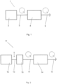
- Figure 1 shows a first embodiment of the device 1 according to the invention.
- This has a radiation source 2, which generates largely non-linearly polarized electromagnetic radiation in the form of circularly or elliptically polarized electromagnetic radiation 3.
- the circularly or elliptically polarized electromagnetic radiation 3 is subsequently amplified by the amplifier 4.
- the non-linear effects occurring here are significantly reduced by the use of circularly or elliptically polarized electromagnetic radiation 3.
- Figure 2 shows a further embodiment of the device 11 according to the invention.
- This has a radiation source 12 for generating linearly polarized electromagnetic radiation 13.
- the linearly polarized electromagnetic radiation 13 is subsequently converted into circularly or elliptically polarized electromagnetic radiation 17 by a polarization converter 16 arranged in the beam path between the radiation source 12 and the amplifier 14.
- the circularly or elliptically polarized electromagnetic radiation 17 is then amplified by the amplifier 14, whereby amplified, circularly or elliptically polarized electromagnetic radiation 15 is produced.
- This embodiment of the device 11 according to the invention can be used as an alternative to the Figure 1 shown can be used.
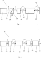
- FIG. 3 shows a further embodiment of the device 21 according to the invention.
- a radiation source 22 is used, which generates linearly polarized electromagnetic radiation 23.
- This linearly polarized electromagnetic radiation 23 is then guided through a polarization splitter 28, which is transparent to linearly polarized electromagnetic radiation 23 in the polarization state as generated by the radiation source 22.
- the linearly polarized electromagnetic radiation 23 transmitted through the polarization splitter 28 is then converted into circularly or elliptically polarized electromagnetic radiation 27 by means of the polarization converter 26.
- This circularly or elliptically polarized electromagnetic radiation 27 is then amplified by means of the amplifier 24.
- the amplified, circularly or elliptically polarized electromagnetic radiation 25 is then reflected by a mirror 30, which determines the radiation direction of the amplified, circularly or elliptically polarized electromagnetic radiation 25.
- the reflected amplified, circularly or elliptically polarized electromagnetic radiation 25 is amplified again by the amplifier 24 and then converted by the polarization converter 26 into linearly polarized electromagnetic radiation 29, the polarization plane of which, however, is perpendicular to the original linearly polarized electromagnetic radiation 23 generated by the radiation source 22, as indicated by the dots and arrows.
- the doubly amplified, linearly polarized electromagnetic radiation 29 is then coupled out of the device 21 via the polarization splitter 28.
- FIG. 4 A further embodiment of the device 31 according to the invention is shown in Figure 4 shown.
- the radiation source 32 generates dispersively stretched, linearly polarized electromagnetic radiation 33.
- the radiation source generates linearly polarized electromagnetic radiation, which is then dispersively stretched by means of a stretcher connected downstream of the radiation source in the beam path.
- the dispersively stretched, linearly polarized electromagnetic radiation 33 is then converted by means of the polarization converter 36 into dispersively stretched, circularly or elliptically polarized electromagnetic radiation 37. This is then amplified by means of the amplifier 34.
- the amplified, dispersively stretched, circularly or elliptically polarized electromagnetic radiation 35 is converted back into dispersively stretched, linearly polarized electromagnetic radiation 39 by means of the further polarization converter 38 connected downstream of the amplifier 34. This is finally compressed in time by means of a compressor 40, which enables the emission of high-energy, linearly polarized electromagnetic radiation 41 of high quality.
Landscapes
- Physics & Mathematics (AREA)
- Electromagnetism (AREA)
- Optics & Photonics (AREA)
- Engineering & Computer Science (AREA)
- Plasma & Fusion (AREA)
- Condensed Matter Physics & Semiconductors (AREA)
- General Physics & Mathematics (AREA)
- Lasers (AREA)
- Amplifiers (AREA)
Description
- Die Erfindung betrifft eine Vorrichtung zum Verstärken von elektromagnetischer Strahlung, mit einer Strahlungsquelle zum Erzeugen der elektromagnetischen Strahlung sowie einem Verstärker zum Verstärken der erzeugten elektromagnetischen Strahlung.
- Derartige Vorrichtungen sind bekannt und finden beispielsweise Einsatz bei der Erzeugung hochenergetischer Laserstrahlung. Die Qualität der elektromagnetischen Strahlung wird beim Verstärken und/oder Transportieren derselben meist durch das Auftreten von Dispersion und/oder nichtlinearen Effekten beeinträchtigt. Während der Einfluss der Dispersion in der Regel gut kompensierbar ist, verursachen nichtlineare Effekte eine deutliche Verschlechterung der Qualität der Laserstrahlung. Der hierbei dominante nichtlineare Effekt ist der Kerr-Effekt. Dieser zeigt sich beispielsweise in Form von Selbstphasenmodulation. Der Kerr-Effekt ist u. a. proportional zur Spitzenintensität sowie zur Wechselwirkungslänge im Verstärker beziehungsweise Transportmedium. Um den Einfluss der Kerr-Nichtlinearität zu reduzieren, ist es bekannt, beispielsweise für die Erzeugung von ultrakurzen Laserimpulsen zeitlich gestreckte Laserimpulse, auch gechirpte Laserimpulse genannt, zu verwenden und diese gechirpten Laserimpulse anschließend zu verstärken. Diese Methode findet bei den so genannten CPA-Systemen (Chirped Pulse Amplification) Anwendung, bei denen die verstärkten Laserimpulse zuletzt meist noch zeitlich komprimiert werden. Des Weiteren ist es bekannt, die durch nichtlineare Effekte hervorgerufene nichtkomprimierbare Phase mit Hilfe von Pulsformung zu kontrollieren.
- Die Auswirkungen der nichtlinearen Effekte treten in optischen Fasern bereits bei sehr geringen Leistungen auf, da die Laserstrahlung in Form von Moden geführt wird. Einerseits wird die Laserstrahlung auf kleine Modenfeldflächen gebunden, was zu hohen Intensitäten führt, andererseits breitet sich die Laserstrahlung quasi-beugungsfrei aus, was wiederum zu großen Wechselwirkungslängen führt. Da die Selbstphasenmodulation umgekehrt proportional zur Modenfeldfläche und proportional zur Faserlänge ist, kann die Verwendung von neuartigen mikrostrukturierten Fasern, wie z.B. LMA-Fasern (Large Mode-Area Fibers) oder LMA-PCF-Fasern (Large Mode-Area Photonic Crystal Fiber), mit großer Modenfeldfläche bei gleichzeitig kleiner Faserlänge den Einfluss nichtlinearer Effekte stark reduzieren.
- Nachteilig bei den bekannten Methoden zur Reduzierung der nichtlinearen Effekte ist, dass relativ komplizierte und kostenintensive bauliche Veränderungen an vorhandenen Vorrichtungen vorgenommen werden müssen, um das gewünschte Ergebnis zu erhalten. Auch die mit diesen Veränderungen verbundene Anpassung der einzelnen Komponenten untereinander ist relativ aufwändig.
- Das Dokument
US 2001/017867 offenbart eine Vorrichtung zum Verstärken von elektromagnetischer Strahlung, mit einer Strahlungsquelle zum Erzeugen der EM Strahlung sowie einem Faserverstärker zum Verstärken der EM Strahlung, die im Verstärker nicht linear, sondern zirkular polarisiert ist, wobei der Verstärker der EM Strahlung eine durch nichtlineare Effekte bedingte nichtlineare Phase aufpräg. - Hiervon ausgehend ist es die Aufgabe der Erfindung, eine Vorrichtung zum Verstärken beziehungsweise Transportieren von elektromagnetischer Strahlung bereitzustellen, welche eine sehr einfach realisierbare und kostengünstige Möglichkeit zur Reduzierung des Einflusses von nichtlinearen Effekten bietet.
- Diese Aufgabe wird ausgehend von einer Vorrichtung wie in Anspruch 1 beschrieben.
- Die Erfindung beruht auf der Erkenntnis, dass der Koeffizient der nichtlinearen Brechzahl von der Polarisation der elektromagnetischen Strahlung abhängt. Dieser Koeffizient ist bei linear polarisierter elektromagnetischer Strahlung etwa 1,5-mal so groß wie bei zirkular polarisierter elektromagnetischer Strahlung. Somit können durch den erfindungsgemäßen Ansatz nichtlineare Effekte wie beispielsweise Selbstphasenmodulation, Kreuzphasenmodulation, Selbstfokussierung, Vierwellen-Mischung und ähnliches reduziert werden. Der erfindungsgemäße Ansatz zur Reduzierung nichtlinearer Effekte ist vergleichsweise einfach und kann zudem in vorhandene Systeme übernommen werden, ohne aufwändige bauliche Modifikationen vornehmen zu müssen. Darüber hinaus kann der erfindungsgemäße Ansatz nahezu problemlos mit den oben beschriebenen herkömmlichen Vorgehensweisen zur Reduzierung von nichtlinearen Effekten kombiniert werden. Von Vorteil ist dabei unter anderem, dass eine Reduzierung der nichtlinearen Effekte zu einer Erhöhung der Spitzenleistung der elektromagnetischen Strahlung führt. Des Weiteren kann die Schwelle für Selbstfokussierung nach oben verschoben werden.
- Die im Verstärker propagierende elektromagnetische Strahlung ist elliptisch oder zirkular polarisiert.
- Nach einer vorteilhaften Ausgestaltung der Erfindung ist vorgesehen, dass die Strahlungsquelle linear polarisierte elektromagnetische Strahlung erzeugt und im Strahlengang zwischen der Strahlungsquelle und dem Verstärker ein Polarisationswandler angeordnet ist. Der Polarisationswandler begünstigt hierbei, dass die linear polarisierte elektromagnetische Strahlung derart gewandelt wird, dass die im Verstärker propagierende elektromagnetische Strahlung weitgehend nicht linear polarisiert ist.
- Der Verstärker, beispielsweise eine optische Glasfaser, prägt der elektromagnetischen Strahlung eine durch nichtlineare Effekte bedingte nichtlineare Phase auf. Diese Phase kann durch den erfindungsgemäßen Ansatz auf einfache Art und Weise deutlich reduziert werden, um so die Qualität beziehungsweise Leistung der verstärkten elektromagnetischen Strahlung zu erhöhen.
- Der Polarisationswandler ist vorzugsweise als Viertelwellenplatte ausgebildet. Dies stellt eine sehr einfache und kostengünstige Realisierungsmöglichkeit dar.
- Nach einer weiteren vorteilhaften Ausgestaltung der Erfindung ist der Polarisationszustand der im Verstärker propagierenden elektromagnetischen Strahlung durch die Lage r > 0.9 einerseits und |ε| > 30°, |ε| > 35° oder |ε| > 40° andererseits auf der Poincaré-Kugel bestimmt. Die Wahl eines dieser Polarisationszustände hat sich als besonders geeignet zur Reduzierung der nichtlinearen Effekte herausgestellt. Es können jedoch auch andere Polarisationszustände ausgewählt werden, welche auf den jeweiligen Anwendungsfall ideal zugeschnitten sind. Zur Verdeutlichung der Parameterwahl wird auf die in
Figur 5 gezeigte Poincaré-Kugel-Darstellung verwiesen, bei der sich linear polarisierte elektromagnetische Strahlung am Äquator befindet, wohingegen zirkular polarisierte elektromagnetische Strahlung an den Polen zu finden ist. - Die Erfindung sieht vor, dass der Verstärker ein weitgehend optisches isotropes Medium aufweist. Erfindugsgemäss ist dieses Medium ein Wellenleiter, oder ein Gas. Der erfindungsgemäße Ansatz zur Reduzierung der nichtlinearen Effekte hat sich für solche Medien als besonders wirksam und vorteilhaft herausgestellt.
- Gemäß einer weiteren vorteilhaften Ausgestaltung der Erfindung ist die elektromagnetische Strahlung aus gepulsten elektromagnetischen Strahlungsimpulsen oder aus einer kontinuierlichen elektromagnetischen Strahlung gebildet. Das Auftreten von nichtlinearen Effekten ist bei beiden Arten elektromagnetischer Strahlung festzustellen. Die erfindungsgemäße Reduzierung der nichtlinearen Effekte findet bei beiden Strahlungsarten gleichermaßen Anwendung und führt zu ähnlich guten Ergebnissen.
- Nach einer weiteren vorteilhaften Ausgestaltung der Erfindung ist im Strahlengang zwischen Strahlungsquelle und Polarisationswandler ein Polarisationsteiler angeordnet und dem Verstärker ein Spiegel nachgeschaltet, wobei der Spiegel die Strahlungsrichtung der verstärkten elektromagnetischen Strahlung umkehrt. Bei dieser Ausgestaltung der Erfindung ist die Verwendung einer Strahlungsquelle von Vorteil, die linear polarisierte elektromagnetische Strahlung erzeugt. Die erzeugte elektromagnetische Strahlung wird zunächst durch den Polarisationsteiler, beispielsweise einen Polarisationsteilerwürfel, geführt und anschließend mittels des Polarisationswandlers in nicht linear polarisierte elektromagnetische Strahlung gewandelt. Diese wird anschließend mittels des Verstärkers, beispielsweise eines Faserverstärkers, verstärkt. Hierbei können nichtlineare Effekte im Verstärker auftreten, die durch die erfindungsgemäße Wahl der im Verstärker propagierenden, weitgehend nicht linear polarisierten elektromagnetischen Strahlung deutlich reduzierbar sind. Die verstärkte, weitgehend nicht linear polarisierte elektromagnetische Strahlung wird anschließend an dem Spiegel zurückreflektiert und erneut mittels des Verstärkers verstärkt, wobei auch bei dieser zweiten Verstärkungsstufe durch die Wahl von weitgehend nicht linear polarisierter elektromagnetischer Strahlung sehr geringe nichtlineare Effekte auftreten. Die zweifach verstärkte, weitgehend nicht linear polarisierte elektromagnetische Strahlung passiert anschließend wieder den Polarisationswandler und wird zu verstärkter, linear polarisierter elektromagnetischer Strahlung, deren Polarisationsebene senkrecht zu der der anfänglichen unverstärkten, linear polarisierten elektromagnetischen Strahlung steht. Die zweifach verstärkte, linear polarisierte elektromagnetische Strahlung wird schließlich über den Polarisationsteiler zu ihrer weiteren Verwendung aus der Vorrichtung ausgekoppelt. Diese Ausgestaltung der Vorrichtung ist somit bei relativ kompaktem Aufbau sehr effektiv.
- Alternativ wird vorgeschlagen, dass dem Verstärker ein weiterer Polarisationswandler nachgeschaltet ist, der die weitgehend nicht linear polarisierte elektromagnetische Strahlung in linear polarisierte elektromagnetische Strahlung wandelt. Bei dieser Ausgestaltung passiert die elektromagnetische Strahlung lediglich einmal den Verstärker.
- Es wird weiter vorgeschlagen, dass im Strahlengang zwischen Polarisationswandler und Verstärker ein Strecker zum zeitlichen Strecken der elektromagnetischen Strahlungsimpulse angeordnet und dem Verstärker beziehungsweise dem weiteren Polarisationswandler ein Kompressor zum Komprimieren der verstärkten elektromagnetischen Strahlungsimpulse nachgeschaltet ist. Diese Ausgestaltung der Erfindung betrifft die Umsetzung des Erfindungsgedankens in einem CPA-System mit den damit verbundenen Vorteilen.
- Weiterhin wird vorgeschlagen, dass im Strahlengang zwischen Strahlungsquelle und Verstärker ein Strecker zum zeitlichen Strecken der elektromagnetischen Strahlungsimpulse angeordnet und dem Verstärker beziehungsweise weiteren Polarisationswandler ein Kompressor zum zeitlichen Komprimieren der verstärkten elektromagnetischen Strahlungsimpulse nachgeschaltet ist.
- Ferner wird vorgeschlagen, dass die Vorrichtung zum spektralen Formen der elektromagnetische Strahlungsimpulse eingerichtet ist.
- Mit der Erfindung wird somit eine Vorrichtung bereitgestellt, welche auf sehr einfache und kostengünstige Art und Weise der Reduzierung von nichtlinearen Effekten bei der Verstärkung von elektromagnetischer Strahlung dient und gleichzeitig problemlos mit vorhandenen Vorrichtungen sowie mit weiteren Methoden zur Reduzierung von nichtlinearen Effekten kombinierbar ist.
- Weitere Vorteile und Merkmale der vorliegenden Erfindung werden anhand der in den Figuren gezeigten Ausführungsbeispiele näher erläutert. Dabei zeigen
- Figur 1:
- ein Ausführungsbeispiel für die erfindungsgemäße Vorrichtung,
- Figur 2:
- ein weiteres Ausführungsbeispiel für die erfindungsgemäße Vorrichtung,
- Figur 3:
- ein weiteres Ausführungsbeispiel für die erfindungsgemäße Vorrichtung,
- Figur 4:
- ein weiteres Ausführungsbeispiel für die erfindungsgemäße Vorrichtung, und
- Figur 5:
- eine Darstellung der Poincaré-Kugel.
-
Figur 1 zeigt ein erstes Ausführungsbeispiel für die erfindungsgemäße Vorrichtung 1. Diese weist eine Strahlungsquelle 2 auf, welche weitgehend nicht linear polarisierte elektromagnetische Strahlung in Form von zirkular oder elliptisch polarisierter elektromagnetischer Strahlung 3 erzeugt. Die zirkular oder elliptisch polarisierte elektromagnetische Strahlung 3 wird anschließend mittels des Verstärkers 4 verstärkt. Die hierbei auftretenden nichtlinearen Effekte sind durch die Verwendung von zirkular oder elliptisch polarisierter elektromagnetischer Strahlung 3 deutlich reduziert. -
Figur 2 zeigt ein weiteres Ausführungsbeispiel für die erfindungsgemäße Vorrichtung 11. Diese weist eine Strahlungsquelle 12 zum Erzeugen von linear polarisierter elektromagnetischer Strahlung 13 auf. Die linear polarisierte elektromagnetische Strahlung 13 wird anschließend von einem im Strahlengang zwischen der Strahlungsquelle 12 und dem Verstärker 14 angeordneten Polarisationswandler 16 in zirkular oder elliptisch polarisierte elektromagnetische Strahlung 17 gewandelt. Die zirkular oder elliptisch polarisierte elektromagnetische Strahlung 17 wird dann mittels des Verstärkers 14 verstärkt, wobei verstärkte, zirkular oder elliptisch polarisierte elektromagnetische Strahlung 15 entsteht. Diese Ausführungsform der erfindungsgemäßen Vorrichtung 11 kann alternativ zu der inFigur 1 gezeigten eingesetzt werden. -
Figur 3 zeigt ein weiteres Ausführungsbeispiel für die erfindungsgemäße Vorrichtung 21. Bei dieser Ausführungsform findet eine Strahlungsquelle 22 Einsatz, welche linear polarisierte elektromagnetische Strahlung 23 erzeugt. Diese linear polarisierte elektromagnetische Strahlung 23 wird anschließend durch einen Polarisationsteiler 28 geführt, welcher für linear polarisierte elektromagnetische Strahlung 23 in dem Polarisationszustand, wie er von der Strahlungsquelle 22 erzeugt wird, durchlässig ist. Die durch den Polarisationsteiler 28 durchgelassene linear polarisierte elektromagnetische Strahlung 23 wird anschließend mittels des Polarisationswandlers 26 in zirkular oder elliptisch polarisierte elektromagnetische Strahlung 27 gewandelt. Diese zirkular oder elliptisch polarisierte elektromagnetische Strahlung 27 wird anschließend mittels des Verstärkers 24 verstärkt. Die verstärkte, zirkular oder elliptisch polarisierte elektromagnetische Strahlung 25 wird anschließend an einem Spiegel 30 reflektiert, der die Strahlungsrichtung der verstärkten, zirkular oder elliptisch polarisierten elektromagnetischen Strahlung 25 umkehrt. Die reflektierte verstärkte, zirkular oder elliptisch polarisierte elektromagnetische Strahlung 25 wird erneut vom Verstärker 24 verstärkt und anschließend mittels des Polarisationswandlers 26 in linear polarisierte elektromagnetische Strahlung 29 gewandelt, deren Polarisationsebene jedoch senkrecht zu der von der Strahlungsquelle 22 erzeugten ursprünglichen linear polarisierten elektromagnetischen Strahlung 23 ist, was durch die Punkte und Pfeile angedeutet sein soll. Die zweifach verstärkte, linear polarisierte elektromagnetische Strahlung 29 wird anschließend über den Polarisationsteiler 28 aus der Vorrichtung 21 ausgekoppelt. - Eine weitere Ausführungsform der erfindungsgemäßen Vorrichtung 31 ist in
Figur 4 gezeigt. Bei dieser Ausführungsform erzeugt die Strahlungsquelle 32 dispersiv gestreckte, linear polarisierte elektromagnetische Strahlung 33. Stattdessen kann aber auch vorgesehen sein, dass die Strahlungsquelle linear polarisierte elektromagnetische Strahlung erzeugt, welche anschließend mittels eines Streckers dispersiv gestreckt wird, der im Strahlengang der Strahlungsquelle nachgeschaltet ist. Die dispersiv gestreckte, linear polarisierte elektromagnetische Strahlung 33 wird anschließend mittels des Polarisationswandlers 36 in dispersiv gestreckte, zirkular oder elliptisch polarisierte elektromagnetische Strahlung 37 gewandelt. Diese wird daraufhin mittels des Verstärkers 34 verstärkt. Die verstärkte, dispersiv gestreckte, zirkular oder elliptisch polarisierte elektromagnetische Strahlung 35 wird mittels des dem Verstärker 34 nachgeschalteten weiteren Polarisationswandlers 38 wieder in dispersiv gestreckte, linear polarisierte elektromagnetische Strahlung 39 gewandelt. Diese wird zuletzt mittels eines Kompressors 40 zeitlich komprimiert, was die Abgabe von hochenergetischer, linear polarisierter elektromagnetischer Strahlung 41 von hoher Qualität ermöglicht. - Die anhand der Figuren beschriebenen Ausführungsbeispiele dienen der Erläuterung und sind nicht beschränkend.
Claims (8)
- Vorrichtung (1) zum Verstärken von elektromagnetischer Strahlung, mit einer Strahlungsquelle (2) zum Erzeugen der elektromagnetischen Strahlung sowie einem Verstärker (4) zum Verstärken der erzeugten elektromagnetischen Strahlung,wobei die im Verstärker (4) propagierende elektromagnetische Strahlung weitgehend nicht linear, nämlich elliptisch oder zirkular polarisiert ist,dadurch gekennzeichnet, dassder Verstärker (14, 24, 34) der elektromagnetischen Strahlung eine durch nichtlineare Effekte bedingte nichtlineare Phase aufprägt, die im Vergleich zu der nichtlinearen Phase bei linearer Polarisation der elektromagnetischen Strahlung reduziert ist, und wobei der Verstärker (14, 24, 34) ein optisch isotropes Medium aufweist, wobei das optisch isotrope Medium ein Wellenleiter oder ein Gas ist.
- Vorrichtung (11, 21, 31) nach Anspruch 1, dadurch gekennzeichnet, dass die Strahlungsquelle (12, 22, 32) linear polarisierte elektromagnetische Strahlung (13, 23, 33) erzeugt und im Strahlengang zwischen der Strahlungsquelle (12, 22, 32) und dem Verstärker (14, 24, 34) ein Polarisationswandler (16, 26, 36) angeordnet ist.
- Vorrichtung (11, 21, 31) nach Anspruch 2, dadurch gekennzeichnet, dass der Polarisationswandler (16, 26, 36) eine Viertelwellenplatte ist.
- Vorrichtung (1, 11, 31) nach Anspruch 2 oder 3, dadurch gekennzeichnet, dass dem Verstärker (4, 14, 34) ein weiterer Polarisationswandler (38) nachgeschaltet ist, der weitgehend nicht linear polarisierte elektromagnetische Strahlung (5, 15, 35) in linear polarisierte elektromagnetische Strahlung (39) wandelt.
- Vorrichtung (11, 21, 31) nach einem der Ansprüche 2 bis 4, dadurch gekennzeichnet, dass im Strahlengang zwischen Polarisationswandler (16, 26, 36) und Verstärker (14, 24, 34) ein Strecker zum zeitlichen Strecken der elektromagnetischen Strahlungsimpulse angeordnet und dem Verstärker (14, 24, 34) bzw. dem weiteren Polarisationswandler (38) ein Kompressor (40) zum zeitlichen Komprimieren der verstärkten elektromagnetischen Strahlungsimpulse nachgeschaltet ist.
- Vorrichtung (1) nach einem der Ansprüche 2 bis 5, dadurch gekennzeichnet, dass im Strahlengang zwischen Strahlungsquelle (2, 12, 22, 32) und Verstärker (4, 14, 24, 34) ein Strecker zum zeitlichen Strecken der elektromagnetischen Strahlungsimpulse angeordnet und dem Verstärker (4, 14, 24, 34) bzw. weiteren Polarisationswandler (38) ein Kompressor zum zeitlichen Komprimieren der verstärkten elektromagnetischen Strahlungsimpulse nachgeschaltet ist.
- Vorrichtung (21) nach einem der Ansprüche 2 bis 6, dadurch gekennzeichnet, dass im Strahlengang zwischen Strahlungsquelle (22) und Polarisationswandler (26) ein Polarisationsteiler (28) angeordnet und dem Verstärker (24) ein Spiegel (30) nachgeschaltet ist, wobei der Spiegel (30) die Strahlungsrichtung der verstärkten elektromagnetischen Strahlung (25) umkehrt.
- Vorrichtung (11, 21, 31) nach einem der Ansprüche 1 bis 7, dadurch gekennzeichnet, dass die elektromagnetische Strahlung aus gepulsten elektromagnetischen Strahlungsimpulsen oder aus einer kontinuierlichen elektromagnetischen Strahlung gebildet ist.
Applications Claiming Priority (3)
| Application Number | Priority Date | Filing Date | Title |
|---|---|---|---|
| DE102009032803A DE102009032803A1 (de) | 2009-07-10 | 2009-07-10 | Vorrichtung zum Verstärken und/oder Transportieren von elektromagnetischer Strahlung |
| EP10757150A EP2452407A2 (de) | 2009-07-10 | 2010-07-09 | Laservorrichtung zum verstärken und/oder transportieren von elektromagnetischer strahlung |
| PCT/EP2010/004187 WO2011003618A2 (de) | 2009-07-10 | 2010-07-09 | Vorrichtung zum verstärken und/oder transportieren von elektromagnetischer strahlung |
Related Parent Applications (1)
| Application Number | Title | Priority Date | Filing Date |
|---|---|---|---|
| EP10757150A Division EP2452407A2 (de) | 2009-07-10 | 2010-07-09 | Laservorrichtung zum verstärken und/oder transportieren von elektromagnetischer strahlung |
Publications (3)
| Publication Number | Publication Date |
|---|---|
| EP3876368A2 EP3876368A2 (de) | 2021-09-08 |
| EP3876368A3 EP3876368A3 (de) | 2021-12-22 |
| EP3876368B1 true EP3876368B1 (de) | 2025-05-14 |
Family
ID=43243008
Family Applications (2)
| Application Number | Title | Priority Date | Filing Date |
|---|---|---|---|
| EP10757150A Ceased EP2452407A2 (de) | 2009-07-10 | 2010-07-09 | Laservorrichtung zum verstärken und/oder transportieren von elektromagnetischer strahlung |
| EP21160423.6A Active EP3876368B1 (de) | 2009-07-10 | 2010-07-09 | Vorrichtung zum verstärken und/oder transportieren von elektromagnetischer strahlung |
Family Applications Before (1)
| Application Number | Title | Priority Date | Filing Date |
|---|---|---|---|
| EP10757150A Ceased EP2452407A2 (de) | 2009-07-10 | 2010-07-09 | Laservorrichtung zum verstärken und/oder transportieren von elektromagnetischer strahlung |
Country Status (5)
| Country | Link |
|---|---|
| US (1) | US8982453B2 (de) |
| EP (2) | EP2452407A2 (de) |
| DE (1) | DE102009032803A1 (de) |
| HU (1) | HUE072296T2 (de) |
| WO (1) | WO2011003618A2 (de) |
Families Citing this family (1)
| Publication number | Priority date | Publication date | Assignee | Title |
|---|---|---|---|---|
| DE202015009433U1 (de) * | 2015-12-22 | 2017-08-18 | PT Photonic Tools GmbH | Strahlführungssystem zur Übertragung von Laserlicht |
Family Cites Families (21)
| Publication number | Priority date | Publication date | Assignee | Title |
|---|---|---|---|---|
| DE1076205B (de) | 1956-03-16 | 1960-02-25 | Marie G R P | Radargeraet mit zirkular polarisierter Strahlung zur Unterscheidung von isotropen und anisotropen Zielen und Verfahren zum Betrieb des Geraetes |
| DE1196255B (de) | 1962-01-20 | 1965-07-08 | Telefunken Patent | Radar-Reflektor fuer zirkular, elliptisch oder in beliebiger Ebene linear polarisierte elektromagnetische Wellen |
| CH451348A (de) * | 1967-02-08 | 1968-05-15 | Inst Angewandte Physik | Vorrichtung zur Frequenzstabilisierung eines Gaslaseroszillators |
| US4222011A (en) * | 1978-10-03 | 1980-09-09 | The United States Of America As Represented By The United States Department Of Energy | Stokes injected Raman capillary waveguide amplifier |
| DE2945466C2 (de) | 1979-11-10 | 1982-04-15 | Licentia Patent-Verwaltungs-Gmbh, 6000 Frankfurt | Streifendiodenlaser mit rückwirkungsfreiem Faserausgang |
| JP3066966B2 (ja) * | 1988-02-29 | 2000-07-17 | ソニー株式会社 | レーザ光源 |
| US4989216A (en) | 1990-04-18 | 1991-01-29 | The United States Of America As Represented By The Secretary Of The Army | Double conjugate laser amplifier |
| EP0574921B1 (de) | 1992-06-19 | 2002-01-16 | Sony Corporation | Vorrichtung zur Erzeugung von Laserstrahlen |
| US5513194A (en) * | 1994-06-30 | 1996-04-30 | Massachusetts Institute Of Technology | Stretched-pulse fiber laser |
| JP3588195B2 (ja) | 1996-07-18 | 2004-11-10 | 浜松ホトニクス株式会社 | 固体レーザ増幅器 |
| US5880877A (en) * | 1997-01-28 | 1999-03-09 | Imra America, Inc. | Apparatus and method for the generation of high-power femtosecond pulses from a fiber amplifier |
| US6208458B1 (en) * | 1997-03-21 | 2001-03-27 | Imra America, Inc. | Quasi-phase-matched parametric chirped pulse amplification systems |
| US6229937B1 (en) * | 1998-09-17 | 2001-05-08 | Corning Incorporated | Circularly polarized fiber in optical circuits |
| DE10009380B4 (de) | 2000-02-29 | 2007-11-08 | Jenoptik Ldt Gmbh | Faserverstärker |
| DE10116076A1 (de) * | 2001-04-01 | 2002-10-10 | Keming Du | Verstärkeranordnung mit doppelbrechendem Strahlversetzer |
| DE10302785A1 (de) * | 2003-01-24 | 2004-08-19 | Menlo Systems Gmbh | Laseranordnung |
| US7349452B2 (en) * | 2004-12-13 | 2008-03-25 | Raydiance, Inc. | Bragg fibers in systems for the generation of high peak power light |
| US7477666B2 (en) * | 2005-04-06 | 2009-01-13 | Polar Onyx, Inc. | All fiber based short pulse amplification at one micron |
| US20080089366A1 (en) * | 2006-05-15 | 2008-04-17 | Polaronyx, Inc. | High energy short pulse fiber laser achieved by combining pulse shaping, polarization shaping and spectral shaping |
| US20090122818A1 (en) | 2007-03-14 | 2009-05-14 | Nettleton John E | Electronic selectable two-color solid state laser |
| US8213070B2 (en) * | 2009-05-06 | 2012-07-03 | Sandia Corporation | Wave-plate structures, power selective optical filter devices, and optical systems using same |
-
2009
- 2009-07-10 DE DE102009032803A patent/DE102009032803A1/de active Pending
-
2010
- 2010-07-09 EP EP10757150A patent/EP2452407A2/de not_active Ceased
- 2010-07-09 US US13/382,980 patent/US8982453B2/en active Active
- 2010-07-09 HU HUE21160423A patent/HUE072296T2/hu unknown
- 2010-07-09 WO PCT/EP2010/004187 patent/WO2011003618A2/de not_active Ceased
- 2010-07-09 EP EP21160423.6A patent/EP3876368B1/de active Active
Non-Patent Citations (1)
| Title |
|---|
| ANONYMOUS, SPIE, PO BOX 10 BELLINGHAM WA 98227-0010 USA, 17 February 1010 (1010-02-17), XP040517654 * |
Also Published As
| Publication number | Publication date |
|---|---|
| EP3876368A2 (de) | 2021-09-08 |
| US20120229888A1 (en) | 2012-09-13 |
| WO2011003618A2 (de) | 2011-01-13 |
| EP2452407A2 (de) | 2012-05-16 |
| WO2011003618A3 (de) | 2011-12-29 |
| US8982453B2 (en) | 2015-03-17 |
| DE102009032803A1 (de) | 2011-01-13 |
| EP3876368A3 (de) | 2021-12-22 |
| HUE072296T2 (hu) | 2025-11-28 |
Similar Documents
| Publication | Publication Date | Title |
|---|---|---|
| DE19549868B4 (de) | Optische Impulsverstärkung unter Verwendung chirp-modulierter Bragg-Gitter | |
| DE102016102839B4 (de) | Faserübertragung von kurzen Laserimpulsen | |
| DE19812203A1 (de) | Quasi-phasenangepaßtes parametrisches Chirpimpulsverstärkungssystem | |
| DE102012009958A1 (de) | Erzeugen von Laserpulsen mit schmaler Spektrallinienbreite basierend auf Chirpen und Strecken von Laserpulsen und nachfolgender Leistungsverstärkung | |
| DE112011103070T5 (de) | Erzeugen von Laserimpulsen auf der Grundlage der Chirped Pulsed Amplification | |
| DE69623219T2 (de) | Vorrichtung und Verfahren zur Veränderung der Spektraleigenschaften von optischen Signalen | |
| DE69200510T2 (de) | Multifokale in Rückwärtsrichtung betriebene Raman-Laser-Vorrichtung. | |
| DE112013003486T5 (de) | Reduzierung der spektralen Bandbreite von Lasern | |
| EP3864726A1 (de) | Multi-apertur-lasersystem | |
| EP3622590B1 (de) | Kurzpulslaser mit hohem zeitlichen kontrast | |
| DE2144201C3 (de) | Ramanlaser | |
| EP1687876B1 (de) | Hochrepetierendes lasersystem mit kompaktem aufbau | |
| DE69006958T2 (de) | Generator für Hochleistungs-Laserimpulse. | |
| DE102017107358A1 (de) | Laserverstärkersystem | |
| DE202015009433U1 (de) | Strahlführungssystem zur Übertragung von Laserlicht | |
| EP3394938B1 (de) | Optische anordnung | |
| DE102018106556A1 (de) | Parametrische Umwandlung von gechirpten Femtosekunden-Pumppulsen | |
| WO2011003618A2 (de) | Vorrichtung zum verstärken und/oder transportieren von elektromagnetischer strahlung | |
| DE102020125544A1 (de) | Erzeugung von ultrakurzen Laserpulsen | |
| DE102016108282A1 (de) | Lasersystem mit Überlagerung von zeitlich oder räumlich separaten Laserpulsen | |
| DE3301092A1 (de) | Mehrfarbenlaser | |
| DE10009380B4 (de) | Faserverstärker | |
| DE102020115753B3 (de) | Kurzpuls-Lasersystem | |
| WO2019091514A1 (de) | Verfahren zur laserverstärkung | |
| EP1775806B1 (de) | Verfahren zur Erzeugung zeitlich rechteckiger Ultrakurzpulse |
Legal Events
| Date | Code | Title | Description |
|---|---|---|---|
| PUAI | Public reference made under article 153(3) epc to a published international application that has entered the european phase |
Free format text: ORIGINAL CODE: 0009012 |
|
| STAA | Information on the status of an ep patent application or granted ep patent |
Free format text: STATUS: THE APPLICATION HAS BEEN PUBLISHED |
|
| AC | Divisional application: reference to earlier application |
Ref document number: 2452407 Country of ref document: EP Kind code of ref document: P |
|
| AK | Designated contracting states |
Kind code of ref document: A2 Designated state(s): AL AT BE BG CH CY CZ DE DK EE ES FI FR GB GR HR HU IE IS IT LI LT LU LV MC MK MT NL NO PL PT RO SE SI SK SM TR |
|
| PUAL | Search report despatched |
Free format text: ORIGINAL CODE: 0009013 |
|
| AK | Designated contracting states |
Kind code of ref document: A3 Designated state(s): AL AT BE BG CH CY CZ DE DK EE ES FI FR GB GR HR HU IE IS IT LI LT LU LV MC MK MT NL NO PL PT RO SE SI SK SM TR |
|
| RIC1 | Information provided on ipc code assigned before grant |
Ipc: H01S 3/23 20060101ALI20211112BHEP Ipc: H01S 3/10 20060101ALI20211112BHEP Ipc: G02B 6/27 20060101ALI20211112BHEP Ipc: H01S 3/00 20060101ALI20211112BHEP Ipc: H01S 5/50 20060101AFI20211112BHEP |
|
| RAP3 | Party data changed (applicant data changed or rights of an application transferred) |
Owner name: FRIEDRICH-SCHILLER-UNIVERSITAET JENA Owner name: FRAUNHOFER-GESELLSCHAFT ZUR FOERDERUNG DER ANGEWANDTEN FORSCHUNG E.V. |
|
| STAA | Information on the status of an ep patent application or granted ep patent |
Free format text: STATUS: REQUEST FOR EXAMINATION WAS MADE |
|
| 17P | Request for examination filed |
Effective date: 20221006 |
|
| RBV | Designated contracting states (corrected) |
Designated state(s): AL AT BE BG CH CY CZ DE DK EE ES FI FR GB GR HR HU IE IS IT LI LT LU LV MC MK MT NL NO PL PT RO SE SI SK SM TR |
|
| GRAP | Despatch of communication of intention to grant a patent |
Free format text: ORIGINAL CODE: EPIDOSNIGR1 |
|
| STAA | Information on the status of an ep patent application or granted ep patent |
Free format text: STATUS: GRANT OF PATENT IS INTENDED |
|
| INTG | Intention to grant announced |
Effective date: 20241206 |
|
| GRAS | Grant fee paid |
Free format text: ORIGINAL CODE: EPIDOSNIGR3 |
|
| GRAA | (expected) grant |
Free format text: ORIGINAL CODE: 0009210 |
|
| STAA | Information on the status of an ep patent application or granted ep patent |
Free format text: STATUS: THE PATENT HAS BEEN GRANTED |
|
| AC | Divisional application: reference to earlier application |
Ref document number: 2452407 Country of ref document: EP Kind code of ref document: P |
|
| AK | Designated contracting states |
Kind code of ref document: B1 Designated state(s): AL AT BE BG CH CY CZ DE DK EE ES FI FR GB GR HR HU IE IS IT LI LT LU LV MC MK MT NL NO PL PT RO SE SI SK SM TR |
|
| REG | Reference to a national code |
Ref country code: GB Ref legal event code: FG4D Free format text: NOT ENGLISH |
|
| REG | Reference to a national code |
Ref country code: CH Ref legal event code: EP |
|
| REG | Reference to a national code |
Ref country code: DE Ref legal event code: R096 Ref document number: 502010017109 Country of ref document: DE |
|
| REG | Reference to a national code |
Ref country code: DE Ref legal event code: R081 Ref document number: 502010017109 Country of ref document: DE Owner name: FRIEDRICH-SCHILLER-UNIVERSITAET JENA, KOERPERS, DE Free format text: FORMER OWNER: ANMELDERANGABEN UNKLAR / UNVOLLSTAENDIG, 80297 MUENCHEN, DE Ref country code: DE Ref legal event code: R081 Ref document number: 502010017109 Country of ref document: DE Owner name: FRAUNHOFER-GESELLSCHAFT ZUR FOERDERUNG DER ANG, DE Free format text: FORMER OWNER: ANMELDERANGABEN UNKLAR / UNVOLLSTAENDIG, 80297 MUENCHEN, DE |
|
| REG | Reference to a national code |
Ref country code: IE Ref legal event code: FG4D Free format text: LANGUAGE OF EP DOCUMENT: GERMAN |
|
| P01 | Opt-out of the competence of the unified patent court (upc) registered |
Free format text: CASE NUMBER: APP_23784/2025 Effective date: 20250519 |
|
| REG | Reference to a national code |
Ref country code: NL Ref legal event code: MP Effective date: 20250514 |
|
| PGFP | Annual fee paid to national office [announced via postgrant information from national office to epo] |
Ref country code: HU Payment date: 20250807 Year of fee payment: 16 |
|
| PG25 | Lapsed in a contracting state [announced via postgrant information from national office to epo] |
Ref country code: PT Free format text: LAPSE BECAUSE OF FAILURE TO SUBMIT A TRANSLATION OF THE DESCRIPTION OR TO PAY THE FEE WITHIN THE PRESCRIBED TIME-LIMIT Effective date: 20250915 Ref country code: FI Free format text: LAPSE BECAUSE OF FAILURE TO SUBMIT A TRANSLATION OF THE DESCRIPTION OR TO PAY THE FEE WITHIN THE PRESCRIBED TIME-LIMIT Effective date: 20250514 Ref country code: ES Free format text: LAPSE BECAUSE OF FAILURE TO SUBMIT A TRANSLATION OF THE DESCRIPTION OR TO PAY THE FEE WITHIN THE PRESCRIBED TIME-LIMIT Effective date: 20250514 |
|
| PGFP | Annual fee paid to national office [announced via postgrant information from national office to epo] |
Ref country code: DE Payment date: 20250722 Year of fee payment: 16 |
|
| REG | Reference to a national code |
Ref country code: LT Ref legal event code: MG9D |
|
| PG25 | Lapsed in a contracting state [announced via postgrant information from national office to epo] |
Ref country code: NO Free format text: LAPSE BECAUSE OF FAILURE TO SUBMIT A TRANSLATION OF THE DESCRIPTION OR TO PAY THE FEE WITHIN THE PRESCRIBED TIME-LIMIT Effective date: 20250814 Ref country code: GR Free format text: LAPSE BECAUSE OF FAILURE TO SUBMIT A TRANSLATION OF THE DESCRIPTION OR TO PAY THE FEE WITHIN THE PRESCRIBED TIME-LIMIT Effective date: 20250815 |
|
| PG25 | Lapsed in a contracting state [announced via postgrant information from national office to epo] |
Ref country code: NL Free format text: LAPSE BECAUSE OF FAILURE TO SUBMIT A TRANSLATION OF THE DESCRIPTION OR TO PAY THE FEE WITHIN THE PRESCRIBED TIME-LIMIT Effective date: 20250514 Ref country code: PL Free format text: LAPSE BECAUSE OF FAILURE TO SUBMIT A TRANSLATION OF THE DESCRIPTION OR TO PAY THE FEE WITHIN THE PRESCRIBED TIME-LIMIT Effective date: 20250514 |
|
| PG25 | Lapsed in a contracting state [announced via postgrant information from national office to epo] |
Ref country code: BG Free format text: LAPSE BECAUSE OF FAILURE TO SUBMIT A TRANSLATION OF THE DESCRIPTION OR TO PAY THE FEE WITHIN THE PRESCRIBED TIME-LIMIT Effective date: 20250514 |
|
| PG25 | Lapsed in a contracting state [announced via postgrant information from national office to epo] |
Ref country code: HR Free format text: LAPSE BECAUSE OF FAILURE TO SUBMIT A TRANSLATION OF THE DESCRIPTION OR TO PAY THE FEE WITHIN THE PRESCRIBED TIME-LIMIT Effective date: 20250514 |
|
| PGFP | Annual fee paid to national office [announced via postgrant information from national office to epo] |
Ref country code: FR Payment date: 20250723 Year of fee payment: 16 |
|
| PG25 | Lapsed in a contracting state [announced via postgrant information from national office to epo] |
Ref country code: IS Free format text: LAPSE BECAUSE OF FAILURE TO SUBMIT A TRANSLATION OF THE DESCRIPTION OR TO PAY THE FEE WITHIN THE PRESCRIBED TIME-LIMIT Effective date: 20250914 |
|
| PG25 | Lapsed in a contracting state [announced via postgrant information from national office to epo] |
Ref country code: LV Free format text: LAPSE BECAUSE OF FAILURE TO SUBMIT A TRANSLATION OF THE DESCRIPTION OR TO PAY THE FEE WITHIN THE PRESCRIBED TIME-LIMIT Effective date: 20250514 |
|
| REG | Reference to a national code |
Ref country code: HU Ref legal event code: AG4A Ref document number: E072296 Country of ref document: HU |
|
| PG25 | Lapsed in a contracting state [announced via postgrant information from national office to epo] |
Ref country code: DK Free format text: LAPSE BECAUSE OF FAILURE TO SUBMIT A TRANSLATION OF THE DESCRIPTION OR TO PAY THE FEE WITHIN THE PRESCRIBED TIME-LIMIT Effective date: 20250514 Ref country code: SM Free format text: LAPSE BECAUSE OF FAILURE TO SUBMIT A TRANSLATION OF THE DESCRIPTION OR TO PAY THE FEE WITHIN THE PRESCRIBED TIME-LIMIT Effective date: 20250514 |
|
| PG25 | Lapsed in a contracting state [announced via postgrant information from national office to epo] |
Ref country code: CZ Free format text: LAPSE BECAUSE OF FAILURE TO SUBMIT A TRANSLATION OF THE DESCRIPTION OR TO PAY THE FEE WITHIN THE PRESCRIBED TIME-LIMIT Effective date: 20250514 |
|
| PG25 | Lapsed in a contracting state [announced via postgrant information from national office to epo] |
Ref country code: EE Free format text: LAPSE BECAUSE OF FAILURE TO SUBMIT A TRANSLATION OF THE DESCRIPTION OR TO PAY THE FEE WITHIN THE PRESCRIBED TIME-LIMIT Effective date: 20250514 |
|
| PG25 | Lapsed in a contracting state [announced via postgrant information from national office to epo] |
Ref country code: RO Free format text: LAPSE BECAUSE OF FAILURE TO SUBMIT A TRANSLATION OF THE DESCRIPTION OR TO PAY THE FEE WITHIN THE PRESCRIBED TIME-LIMIT Effective date: 20250514 Ref country code: SK Free format text: LAPSE BECAUSE OF FAILURE TO SUBMIT A TRANSLATION OF THE DESCRIPTION OR TO PAY THE FEE WITHIN THE PRESCRIBED TIME-LIMIT Effective date: 20250514 |
|
| PG25 | Lapsed in a contracting state [announced via postgrant information from national office to epo] |
Ref country code: IT Free format text: LAPSE BECAUSE OF FAILURE TO SUBMIT A TRANSLATION OF THE DESCRIPTION OR TO PAY THE FEE WITHIN THE PRESCRIBED TIME-LIMIT Effective date: 20250514 |
|
| REG | Reference to a national code |
Ref country code: DE Ref legal event code: R097 Ref document number: 502010017109 Country of ref document: DE |
|
| REG | Reference to a national code |
Ref country code: CH Ref legal event code: H13 Free format text: ST27 STATUS EVENT CODE: U-0-0-H10-H13 (AS PROVIDED BY THE NATIONAL OFFICE) Effective date: 20260224 |
|
| PG25 | Lapsed in a contracting state [announced via postgrant information from national office to epo] |
Ref country code: LU Free format text: LAPSE BECAUSE OF NON-PAYMENT OF DUE FEES Effective date: 20250709 |
|
| PLBE | No opposition filed within time limit |
Free format text: ORIGINAL CODE: 0009261 |
|
| STAA | Information on the status of an ep patent application or granted ep patent |
Free format text: STATUS: NO OPPOSITION FILED WITHIN TIME LIMIT |
|
| REG | Reference to a national code |
Ref country code: CH Ref legal event code: L10 Free format text: ST27 STATUS EVENT CODE: U-0-0-L10-L00 (AS PROVIDED BY THE NATIONAL OFFICE) Effective date: 20260325 |
|
| REG | Reference to a national code |
Ref country code: BE Ref legal event code: MM Effective date: 20250731 |
|
| PG25 | Lapsed in a contracting state [announced via postgrant information from national office to epo] |
Ref country code: BE Free format text: LAPSE BECAUSE OF NON-PAYMENT OF DUE FEES Effective date: 20250731 |
|
| 26N | No opposition filed |
Effective date: 20260217 |
|
| PG25 | Lapsed in a contracting state [announced via postgrant information from national office to epo] |
Ref country code: CH Free format text: LAPSE BECAUSE OF NON-PAYMENT OF DUE FEES Effective date: 20250731 |
|
| GBPC | Gb: european patent ceased through non-payment of renewal fee |
Effective date: 20250814 |