EP3876306A1 - Battery module - Google Patents
Battery module Download PDFInfo
- Publication number
- EP3876306A1 EP3876306A1 EP19896335.7A EP19896335A EP3876306A1 EP 3876306 A1 EP3876306 A1 EP 3876306A1 EP 19896335 A EP19896335 A EP 19896335A EP 3876306 A1 EP3876306 A1 EP 3876306A1
- Authority
- EP
- European Patent Office
- Prior art keywords
- bus bar
- battery module
- safety unit
- battery
- bar body
- Prior art date
- Legal status (The legal status is an assumption and is not a legal conclusion. Google has not performed a legal analysis and makes no representation as to the accuracy of the status listed.)
- Pending
Links
Images


Classifications
-
- H—ELECTRICITY
- H01—ELECTRIC ELEMENTS
- H01M—PROCESSES OR MEANS, e.g. BATTERIES, FOR THE DIRECT CONVERSION OF CHEMICAL ENERGY INTO ELECTRICAL ENERGY
- H01M50/00—Constructional details or processes of manufacture of the non-active parts of electrochemical cells other than fuel cells, e.g. hybrid cells
- H01M50/50—Current conducting connections for cells or batteries
- H01M50/502—Interconnectors for connecting terminals of adjacent batteries; Interconnectors for connecting cells outside a battery casing
- H01M50/521—Interconnectors for connecting terminals of adjacent batteries; Interconnectors for connecting cells outside a battery casing characterised by the material
-
- H—ELECTRICITY
- H01—ELECTRIC ELEMENTS
- H01M—PROCESSES OR MEANS, e.g. BATTERIES, FOR THE DIRECT CONVERSION OF CHEMICAL ENERGY INTO ELECTRICAL ENERGY
- H01M10/00—Secondary cells; Manufacture thereof
- H01M10/42—Methods or arrangements for servicing or maintenance of secondary cells or secondary half-cells
-
- H—ELECTRICITY
- H01—ELECTRIC ELEMENTS
- H01M—PROCESSES OR MEANS, e.g. BATTERIES, FOR THE DIRECT CONVERSION OF CHEMICAL ENERGY INTO ELECTRICAL ENERGY
- H01M50/00—Constructional details or processes of manufacture of the non-active parts of electrochemical cells other than fuel cells, e.g. hybrid cells
- H01M50/20—Mountings; Secondary casings or frames; Racks, modules or packs; Suspension devices; Shock absorbers; Transport or carrying devices; Holders
- H01M50/204—Racks, modules or packs for multiple batteries or multiple cells
- H01M50/207—Racks, modules or packs for multiple batteries or multiple cells characterised by their shape
- H01M50/209—Racks, modules or packs for multiple batteries or multiple cells characterised by their shape adapted for prismatic or rectangular cells
-
- H—ELECTRICITY
- H01—ELECTRIC ELEMENTS
- H01M—PROCESSES OR MEANS, e.g. BATTERIES, FOR THE DIRECT CONVERSION OF CHEMICAL ENERGY INTO ELECTRICAL ENERGY
- H01M50/00—Constructional details or processes of manufacture of the non-active parts of electrochemical cells other than fuel cells, e.g. hybrid cells
- H01M50/20—Mountings; Secondary casings or frames; Racks, modules or packs; Suspension devices; Shock absorbers; Transport or carrying devices; Holders
- H01M50/204—Racks, modules or packs for multiple batteries or multiple cells
- H01M50/207—Racks, modules or packs for multiple batteries or multiple cells characterised by their shape
- H01M50/211—Racks, modules or packs for multiple batteries or multiple cells characterised by their shape adapted for pouch cells
-
- H—ELECTRICITY
- H01—ELECTRIC ELEMENTS
- H01M—PROCESSES OR MEANS, e.g. BATTERIES, FOR THE DIRECT CONVERSION OF CHEMICAL ENERGY INTO ELECTRICAL ENERGY
- H01M50/00—Constructional details or processes of manufacture of the non-active parts of electrochemical cells other than fuel cells, e.g. hybrid cells
- H01M50/50—Current conducting connections for cells or batteries
- H01M50/502—Interconnectors for connecting terminals of adjacent batteries; Interconnectors for connecting cells outside a battery casing
- H01M50/507—Interconnectors for connecting terminals of adjacent batteries; Interconnectors for connecting cells outside a battery casing comprising an arrangement of two or more busbars within a container structure, e.g. busbar modules
-
- H—ELECTRICITY
- H01—ELECTRIC ELEMENTS
- H01M—PROCESSES OR MEANS, e.g. BATTERIES, FOR THE DIRECT CONVERSION OF CHEMICAL ENERGY INTO ELECTRICAL ENERGY
- H01M50/00—Constructional details or processes of manufacture of the non-active parts of electrochemical cells other than fuel cells, e.g. hybrid cells
- H01M50/50—Current conducting connections for cells or batteries
- H01M50/543—Terminals
- H01M50/552—Terminals characterised by their shape
- H01M50/553—Terminals adapted for prismatic, pouch or rectangular cells
-
- H—ELECTRICITY
- H01—ELECTRIC ELEMENTS
- H01M—PROCESSES OR MEANS, e.g. BATTERIES, FOR THE DIRECT CONVERSION OF CHEMICAL ENERGY INTO ELECTRICAL ENERGY
- H01M50/00—Constructional details or processes of manufacture of the non-active parts of electrochemical cells other than fuel cells, e.g. hybrid cells
- H01M50/50—Current conducting connections for cells or batteries
- H01M50/572—Means for preventing undesired use or discharge
- H01M50/574—Devices or arrangements for the interruption of current
- H01M50/581—Devices or arrangements for the interruption of current in response to temperature
-
- H—ELECTRICITY
- H01—ELECTRIC ELEMENTS
- H01M—PROCESSES OR MEANS, e.g. BATTERIES, FOR THE DIRECT CONVERSION OF CHEMICAL ENERGY INTO ELECTRICAL ENERGY
- H01M2200/00—Safety devices for primary or secondary batteries
-
- H—ELECTRICITY
- H01—ELECTRIC ELEMENTS
- H01M—PROCESSES OR MEANS, e.g. BATTERIES, FOR THE DIRECT CONVERSION OF CHEMICAL ENERGY INTO ELECTRICAL ENERGY
- H01M2200/00—Safety devices for primary or secondary batteries
- H01M2200/10—Temperature sensitive devices
-
- H—ELECTRICITY
- H01—ELECTRIC ELEMENTS
- H01M—PROCESSES OR MEANS, e.g. BATTERIES, FOR THE DIRECT CONVERSION OF CHEMICAL ENERGY INTO ELECTRICAL ENERGY
- H01M2220/00—Batteries for particular applications
- H01M2220/20—Batteries in motive systems, e.g. vehicle, ship, plane
-
- Y—GENERAL TAGGING OF NEW TECHNOLOGICAL DEVELOPMENTS; GENERAL TAGGING OF CROSS-SECTIONAL TECHNOLOGIES SPANNING OVER SEVERAL SECTIONS OF THE IPC; TECHNICAL SUBJECTS COVERED BY FORMER USPC CROSS-REFERENCE ART COLLECTIONS [XRACs] AND DIGESTS
- Y02—TECHNOLOGIES OR APPLICATIONS FOR MITIGATION OR ADAPTATION AGAINST CLIMATE CHANGE
- Y02E—REDUCTION OF GREENHOUSE GAS [GHG] EMISSIONS, RELATED TO ENERGY GENERATION, TRANSMISSION OR DISTRIBUTION
- Y02E60/00—Enabling technologies; Technologies with a potential or indirect contribution to GHG emissions mitigation
- Y02E60/10—Energy storage using batteries
Definitions
- the present disclosure relates to a battery module, and more particularly to a battery module including a bus bar with improved safety.
- secondary batteries are easily applied to various product groups and has electrical characteristics such as high energy density, it is universally applied not only for a portable device but also for an electric vehicle or a hybrid electric vehicle, an energy storage system or the like, which is driven by an electric driving source.
- the secondary battery is attracting attention as a new environment-friendly energy source for improving energy efficiency since it gives a primary advantage of remarkably reducing the use of fossil fuels and also does not generate by-products from the use of energy at all.
- a battery pack for use in electric vehicles has a structure in which a plurality of cell assemblies, each including a plurality of unit cells, are connected in series to obtain a high output.
- the unit cell can be repeatedly charged and discharged by electrochemical reactions among components, which include a positive electrode current collector, a negative electrode current collector, a separator, an active material, an electrolyte and the like.
- the battery module set in this way includes a plurality of battery cells stacked on each other and a bus bar for electrically connecting electrode leads of the plurality of battery cells.
- Such a middle or large-sized battery module is designed so that when the pressure inside the battery cell rises to ensure safety, the lead inside the cell is melted to cut off electric current.
- the pressure inside the battery cell rises since it operates depending on whether the pressure inside the cell rises, there is a problem of a pouch deformation in the case of a pouch type cell. For this reason, even in middle or large-sized battery modules, when the temperature inside the cell rises, there is an increasing need for a means that can stably secure safety by cutting off electric current.
- the present disclosure has been made to solve the above problems, and it is therefore an object to provide a battery module including a bus bar which can secure safety in the battery module by cutting off electric current in abnormal situations such as thermal runaway due to temperature rise, and at the same time, is not high in resistance under normal conditions and thus can maintain performance equivalent to the existing one.
- a battery module includes a plurality of battery cells, and a bus bar for electrically connecting the plurality of battery cells, wherein the bus bar includes a bus bar body, and a safety unit inserted into a part of the bus bar body and surrounded by the bus bar body, and wherein the safety unit includes a volumetric expansion resin, a conductive material and an adhesive.
- the safety unit may have the same thickness as the bus bar body.
- the volumetric expansion resin may include a material that generates gas in an environment at a predetermined temperature or higher.
- the volumetric expansion resin may include melamine cyanurate.
- the safety unit may be formed by mixing the volumetric expansion resin, the conductive material, and the adhesive.
- the resistance of the safety unit can increase to cut off electric current.
- the safety unit may have conductivity by the conductive material.
- the conductive material may be metal powder or carbon powder.
- the predetermined temperature may be 110°C to 120°C.
- the bus bar includes a slit formed in the bus bar body, into which a lead extended from the plurality of battery cells is inserted; and a terminal connection part having a bent shape extending from one end of the bus bar body, and the safety unit may be located between a slit and a terminal connection part.
- the safety unit may have a shape in which a plurality of stripes are gathered.
- the battery pack according to another exemplary embodiment of the present disclosure may include the above-mentioned at least one battery module, and a pack case configured to package the at least one battery module.
- a device may include the above-mentioned at least one battery pack.
- the embodiments it is possible to secure safety in the battery module by cutting off electric current in abnormal situations such as thermal runaway due to temperature rise, and at the same time, it is possible to improve the safety of the battery module by using a bus bar which is not high in resistance under normal conditions, and thus can maintain performance equivalent to the existing one.
- planar when referred to as “planar”, it means when a target portion is viewed from the top, and when referred to as “cross-sectional”, it means when a target portion is viewed from the side of a cross section cut vertically.
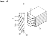
- FIG. 1 is an enlarged view of a part of a battery module according to an exemplary embodiment of the present disclosure.
- the battery module 10 includes a battery cell stack in which a plurality of battery cells 100 are stacked, and a bus bar 200 for electrically connecting the plurality of battery cells 100.
- the individual battery cell 100 constituting the battery cell stack is for example a pouch type battery cell, and may have a shape in which an electrode assembly is accommodated in a pouch case. They can be electrically connected to each other.
- the electrode assembly may include a positive electrode plate, a negative electrode plate and a separator, and an electrode assembly having a known structure can be adopted, and so a detailed description thereof will be omitted here.
- a pair of electrode leads 110 connected to the electrode assembly may be drawn to the outside of the pouch case, for example, in the same direction or opposite direction.
- a pouch-type battery cell 100 having a shape in which a pair of electrode leads 110 are drawn in opposite directions are shown for convenience of illustration, but the battery cell 100 applied to the battery module according to the present disclosure is not necessarily limited thereto, and a pair of electrode leads 110 may be drawn in the same direction.
- the battery cells 100 are stacked such that electrode leads 110 having the same polarity are located in the same direction. This is because, when the electrode leads 110 are electrically connected by using a bus bar 200, the electrode leads 110 having the same polarity must be connected to each other. As the electrode leads 110 having the same polarity are electrically connected to each other, the respective battery cells 100 are connected in parallel.
- the electrode lead 110 for example, a thin metal plate of aluminum (Al) material coated with nickel (Ni) may be used. In order to facilitate the welding work for coupling these electrode leads 110 and bus bars 200, the surface of the electrode leads 110 may be coated with tin (Sn) .
- the bus bar 200 is for electrically connecting the electrode leads 110 provided in each battery cell 100 and may include a slit 202 into which the electrode leads 110 can be inserted.
- the electrode leads 110 inserted into the slit 202 may be bent so that the electrode leads 110 and the bus bars 200 are in surface contact with each other, which are then connected by welding or the like, thereby achieving an electrical connection.
- the bus bar may include a first bus bar 210 used to connect the battery cells 100 in the battery module 10 in parallel, and a second bus bar 220 used to electrically connect the battery module 10 to an external terminal.
- the first bus bar 210 may include a planar bus bar body 211 and a slit 202 formed therein as shown in FIG. 1 , but the structure is not limited thereto. In other words, a shape including a plurality of slits in one body, and additional holes and protrusions for coupling with components other than electrode leads can be included, which can be appropriately modified as needed. As shown in FIG.
- a second bus bar 220 may include a bus bar body 221 including a slit 202, and a terminal connection part 222 configured by being extended from one end of the bus bar body 221 and bent so as to be substantially perpendicular to the bus bar body 221 in a direction opposite to the battery module 100.
- the terminal connection part 222 may include one or more holes 223 that can be connected to external terminals.
- the bus bar 200 is coupled to a bus bar frame (not shown) or the like, and a module frame (not shown) accommodating a battery cell stack is coupled with the bus bar frame, so that the bus bar 200 can be coupled with an electrode lead 110, without being not particularly limited.
- FIG. 2 is a front view illustrating a bus bar of the battery module shown in FIG. 1
- FIG. 3 is a view illustrating a cross section taken along line III-III' of the bus bar shown in FIG 2 .
- the bus bar 200 (in this embodiment, the second bus bar 220 will be described as an example) includes a safety unit 230 inserted into a part of the bus bar body 221 and surrounded by the bus bar body 221.
- the safety unit 230 includes a volumetric expansion resin, a conductive material, and an adhesive. That is, the safety unit 230 may be formed by filling paste-like materials in which the volumetric expansion resin, the conductive material and the adhesive are mixed, in a space (hole) formed in the bus bar body 221, and then curing the same. For this reason, the safety unit 230 may have the same thickness as the bus bar body 221.
- the volumetric expansion resin included in the safety unit 230 includes materials that generates gas in an environment at a predetermined temperature or higher, specifically, an environment at 110°C to 120°C or higher. That is, the volumetric expansion resin is a material that can be thermally decomposed at a temperature of 110°C to 120°C or more to generate gas. Examples of such volume expansion resins include melamine cyanurate.
- the conductive material included in the safety unit 230 may be a conductive powder, for example, a metal powder or a carbon powder.
- the metal powder may include silver, aluminum, gold, lead and the like, but are not particularly limited.
- the conductive powder can be used by mixing with an adhesive, or a commercially available metal paste may be mixed with the volumetric expansion resin and the adhesive described later, thereby forming a safety unit 230. Since the safety unit 230 includes such a conductive material, it allows current to be smoothly transmitted without causing an increase in resistance of the bus bar 200 by the safety unit 230 when the battery module operates normally (that is, when no abnormal temperature rise occurs).
- the adhesive included in the safety unit 230 is not particularly limited as long as it is a resin that can be mixed with the volumetric expansion resin and the conductive material to form a paste and be cured.
- a resin that can be mixed with the volumetric expansion resin and the conductive material to form a paste and be cured for example, an epoxy resin or the like can be used.
- the volumetric expansion resin, the conductive material, and the adhesive are mixed and made in the form of a paste, which is then filled into a space (hole) formed in the bus bar body 221 and then cured, thereby forming a safety unit 230.
- the volumetric expansion resin included in the safety unit 230 is thermally decomposed to generate gas when the temperature inside the battery module is abnormally increased (thermal runaway) to be 110°C to 120°C or more.
- thermal runaway for example, when melamine isocyanurate is used as the volumetric expansion resin, nitrogen gas is generated by thermal decomposition. When gas is generated in this way, the safety unit 230 expands and resistance increases.
- the safety unit 230 acts as a resistance layer and resistance increases between both sides around the safety unit 230, the current does not flow or the amount of flowing current decreases. Therefore, when a sudden temperature rise occurs due to an abnormal operation, it is possible to efficiently cut off electric current to improve the safety of the battery module.
- the safety unit 230 when the safety unit 230 is formed by mixing the volumetric expansion resin, the conductive material, and the adhesive as shown in FIG. 3 , the safety unit 230 may be formed to the same thickness as the bus bar body 221. Therefore, even if the safety unit 230 is added, the structure itself of the conventional bus bar 200 does not change, and therefore, the configuration of the safety unit 230 can be easily adopted without changing the design.
- the safety unit 230 included in the second bus bar 220 has been described as an example, but the safety unit 230 may be included in a first bus bar 210, and it may also be employed for the safety of other components employed for electrical connection, without being particularly limited.
- the safety unit 230 when the safety unit 230 is located in the vicinity of the terminal connection part 222 connected to an external terminal, the current flow to the outside is cut off, and thus, there is an advantage in that the effect of cutting off electrical current can be achieved more quickly and effectively for the entire battery module 10. That is, as shown in FIG. 2 , the safety unit 230 may be located between the slit 202 and the terminal connection part 222. Thereby, the electrical connection to the entire battery module 10 from the outside can be quickly cut off even by using the safety unit 230 with a smaller amount and a smaller area.
- FIG. 4 is a front view illustrating a bus bar according to another exemplary embodiment of the present disclosure.
- the bus bar 200 may include a safety unit 231 formed in a form in which a plurality of stripes are gathered.
- Other configurations except for the shape of the safety unit 231 are the same as in the previous embodiment, and so a description thereof will be omitted here.
- the safety unit 231 included in the bus bar 200 of the present embodiment has a shape in which a plurality of stripes are gathered, which may be formed by a process in which a plurality of pattern-shaped holes are formed in the bus bar body 221, and then filled with a paste obtained by mixing the volumetric expansion resin, the conductive material and the adhesive, followed by curing. According to this, each region filled with the paste is narrow, and therefore, even if the viscosity of the paste is slightly diluted, it is possible to form the safety unit 231 without being affected by this, thereby improving workability.
- one or more battery modules according to an exemplary embodiment of the present disclosure may be packaged in a pack case to form a battery pack.
- the above-mentioned battery module and a battery pack including the same may be applied to various devices. These devices may be applied to vehicles such as an electric bicycle, an electric vehicle, a hybrid vehicle, but the present disclosure is not limited thereto and can be applied to various devices that can use the battery module and the battery pack including the same, which also belongs to the scope of the present disclosure.
Landscapes
- Chemical & Material Sciences (AREA)
- Chemical Kinetics & Catalysis (AREA)
- Electrochemistry (AREA)
- General Chemical & Material Sciences (AREA)
- Engineering & Computer Science (AREA)
- Manufacturing & Machinery (AREA)
- Battery Mounting, Suspending (AREA)
- Connection Of Batteries Or Terminals (AREA)
Abstract
Description
- This application claims the benefit of priority based on
Korean Patent Application No. 10-2018-0161298 filed on December 13, 2018 - The present disclosure relates to a battery module, and more particularly to a battery module including a bus bar with improved safety.
- Since secondary batteries are easily applied to various product groups and has electrical characteristics such as high energy density, it is universally applied not only for a portable device but also for an electric vehicle or a hybrid electric vehicle, an energy storage system or the like, which is driven by an electric driving source. The secondary battery is attracting attention as a new environment-friendly energy source for improving energy efficiency since it gives a primary advantage of remarkably reducing the use of fossil fuels and also does not generate by-products from the use of energy at all.
- A battery pack for use in electric vehicles has a structure in which a plurality of cell assemblies, each including a plurality of unit cells, are connected in series to obtain a high output. In addition, the unit cell can be repeatedly charged and discharged by electrochemical reactions among components, which include a positive electrode current collector, a negative electrode current collector, a separator, an active material, an electrolyte and the like.
- Meanwhile, as the need for a large capacity structure is increasing along with the utilization as an energy storage source in recent years, there is a growing demand for a battery pack with a multi-module structure in which a plurality of battery modules, each including a plurality of secondary batteries connected in series and/or in parallel, are integrated.
- Meanwhile, when a plurality of battery cells are connected in series or in parallel to configure a battery pack, it is common to configure a battery module composed of at least one battery cell first, and then configure a battery pack by using at least one battery module and adding other components. The number of battery cells included in the battery pack, or the number of battery cells included in the battery module may be variously set according to the required output voltage or the demanded charge/discharge capacity. The battery module set in this way includes a plurality of battery cells stacked on each other and a bus bar for electrically connecting electrode leads of the plurality of battery cells.
- Such a middle or large-sized battery module is designed so that when the pressure inside the battery cell rises to ensure safety, the lead inside the cell is melted to cut off electric current. However, since it operates depending on whether the pressure inside the cell rises, there is a problem of a pouch deformation in the case of a pouch type cell. For this reason, even in middle or large-sized battery modules, when the temperature inside the cell rises, there is an increasing need for a means that can stably secure safety by cutting off electric current.
- The present disclosure has been made to solve the above problems, and it is therefore an object to provide a battery module including a bus bar which can secure safety in the battery module by cutting off electric current in abnormal situations such as thermal runaway due to temperature rise, and at the same time, is not high in resistance under normal conditions and thus can maintain performance equivalent to the existing one.
- However, the problem to be solved by the embodiments of the present disclosure is not limited to the above-described problems, and can be variously expanded within the scope of the technical idea included in the present disclosure.
- A battery module according to an exemplary embodiment of the present disclosure includes a plurality of battery cells, and a bus bar for electrically connecting the plurality of battery cells, wherein the bus bar includes a bus bar body, and a safety unit inserted into a part of the bus bar body and surrounded by the bus bar body, and wherein the safety unit includes a volumetric expansion resin, a conductive material and an adhesive.
- The safety unit may have the same thickness as the bus bar body.
- The volumetric expansion resin may include a material that generates gas in an environment at a predetermined temperature or higher.
- The volumetric expansion resin may include melamine cyanurate.
- The safety unit may be formed by mixing the volumetric expansion resin, the conductive material, and the adhesive.
- By generating gas from the volumetric expansion resin in the environment at a predetermined temperature or higher, the resistance of the safety unit can increase to cut off electric current.
- In an environment below a predetermined temperature, the safety unit may have conductivity by the conductive material.
- The conductive material may be metal powder or carbon powder.
- The predetermined temperature may be 110°C to 120°C.
- The bus bar includes a slit formed in the bus bar body, into which a lead extended from the plurality of battery cells is inserted; and a terminal connection part having a bent shape extending from one end of the bus bar body, and the safety unit may be located between a slit and a terminal connection part.
- The safety unit may have a shape in which a plurality of stripes are gathered.
- The battery pack according to another exemplary embodiment of the present disclosure may include the above-mentioned at least one battery module, and a pack case configured to package the at least one battery module.
- A device according to another exemplary embodiment of the present disclosure may include the above-mentioned at least one battery pack.
- According to the embodiments, it is possible to secure safety in the battery module by cutting off electric current in abnormal situations such as thermal runaway due to temperature rise, and at the same time, it is possible to improve the safety of the battery module by using a bus bar which is not high in resistance under normal conditions, and thus can maintain performance equivalent to the existing one.
-
-
FIG. 1 is an enlarged view of a part of a battery module according to an exemplary embodiment of the present disclosure. -
FIG. 2 is a front view illustrating a bus bar of the battery module shown inFIG. 1 . -
FIG. 3 is a view illustrating a cross section taken along line III-III' of the bus bar shown inFIG 2 . -
FIG. 4 is a front view illustrating a bus bar according to another exemplary embodiment of the present disclosure. - Hereinafter, various embodiments of the present disclosure will be described in detail with reference to the accompanying drawings so that those skilled in the art can easily implement them. The present disclosure may be modified in various different ways, and is not limited to the embodiments set forth herein.
- Further, throughout the specification, when a part is referred to as "including" a certain component, it means that it can further include other components, without excluding the other components, unless otherwise stated.
- Further, throughout the specification, when referred to as "planar", it means when a target portion is viewed from the top, and when referred to as "cross-sectional", it means when a target portion is viewed from the side of a cross section cut vertically.
-
FIG. 1 is an enlarged view of a part of a battery module according to an exemplary embodiment of the present disclosure. - Referring to
FIG. 1 , thebattery module 10 according to an exemplary embodiment of the present disclosure includes a battery cell stack in which a plurality ofbattery cells 100 are stacked, and abus bar 200 for electrically connecting the plurality ofbattery cells 100. - The
individual battery cell 100 constituting the battery cell stack is for example a pouch type battery cell, and may have a shape in which an electrode assembly is accommodated in a pouch case. They can be electrically connected to each other. The electrode assembly may include a positive electrode plate, a negative electrode plate and a separator, and an electrode assembly having a known structure can be adopted, and so a detailed description thereof will be omitted here. - A pair of electrode leads 110 connected to the electrode assembly may be drawn to the outside of the pouch case, for example, in the same direction or opposite direction. In the figures of the present disclosure, only a pouch-
type battery cell 100 having a shape in which a pair ofelectrode leads 110 are drawn in opposite directions are shown for convenience of illustration, but thebattery cell 100 applied to the battery module according to the present disclosure is not necessarily limited thereto, and a pair of electrode leads 110 may be drawn in the same direction. - The
battery cells 100 are stacked such that electrode leads 110 having the same polarity are located in the same direction. This is because, when the electrode leads 110 are electrically connected by using abus bar 200, the electrode leads 110 having the same polarity must be connected to each other. As the electrode leads 110 having the same polarity are electrically connected to each other, therespective battery cells 100 are connected in parallel. - As the electrode lead 110, for example, a thin metal plate of aluminum (Al) material coated with nickel (Ni) may be used. In order to facilitate the welding work for coupling these electrode leads 110 and
bus bars 200, the surface of the electrode leads 110 may be coated with tin (Sn) . - The
bus bar 200 is for electrically connecting the electrode leads 110 provided in eachbattery cell 100 and may include aslit 202 into which the electrode leads 110 can be inserted. The electrode leads 110 inserted into theslit 202 may be bent so that the electrode leads 110 and thebus bars 200 are in surface contact with each other, which are then connected by welding or the like, thereby achieving an electrical connection. - The bus bar may include a
first bus bar 210 used to connect thebattery cells 100 in thebattery module 10 in parallel, and asecond bus bar 220 used to electrically connect thebattery module 10 to an external terminal. Thefirst bus bar 210 may include a planarbus bar body 211 and aslit 202 formed therein as shown inFIG. 1 , but the structure is not limited thereto. In other words, a shape including a plurality of slits in one body, and additional holes and protrusions for coupling with components other than electrode leads can be included, which can be appropriately modified as needed. As shown inFIG. 1 , asecond bus bar 220 may include abus bar body 221 including aslit 202, and aterminal connection part 222 configured by being extended from one end of thebus bar body 221 and bent so as to be substantially perpendicular to thebus bar body 221 in a direction opposite to thebattery module 100. Theterminal connection part 222 may include one ormore holes 223 that can be connected to external terminals. - The
bus bar 200 is coupled to a bus bar frame (not shown) or the like, and a module frame (not shown) accommodating a battery cell stack is coupled with the bus bar frame, so that thebus bar 200 can be coupled with anelectrode lead 110, without being not particularly limited. -
FIG. 2 is a front view illustrating a bus bar of the battery module shown inFIG. 1 , andFIG. 3 is a view illustrating a cross section taken along line III-III' of the bus bar shown inFIG 2 . - Referring to
FIGS. 1 ,2, and 3 , the bus bar 200 (in this embodiment, thesecond bus bar 220 will be described as an example) includes asafety unit 230 inserted into a part of thebus bar body 221 and surrounded by thebus bar body 221. - The
safety unit 230 includes a volumetric expansion resin, a conductive material, and an adhesive. That is, thesafety unit 230 may be formed by filling paste-like materials in which the volumetric expansion resin, the conductive material and the adhesive are mixed, in a space (hole) formed in thebus bar body 221, and then curing the same. For this reason, thesafety unit 230 may have the same thickness as thebus bar body 221. - The volumetric expansion resin included in the
safety unit 230 includes materials that generates gas in an environment at a predetermined temperature or higher, specifically, an environment at 110°C to 120°C or higher. That is, the volumetric expansion resin is a material that can be thermally decomposed at a temperature of 110°C to 120°C or more to generate gas. Examples of such volume expansion resins include melamine cyanurate. - The conductive material included in the
safety unit 230 may be a conductive powder, for example, a metal powder or a carbon powder. Examples of the metal powder may include silver, aluminum, gold, lead and the like, but are not particularly limited. The conductive powder can be used by mixing with an adhesive, or a commercially available metal paste may be mixed with the volumetric expansion resin and the adhesive described later, thereby forming asafety unit 230. Since thesafety unit 230 includes such a conductive material, it allows current to be smoothly transmitted without causing an increase in resistance of thebus bar 200 by thesafety unit 230 when the battery module operates normally (that is, when no abnormal temperature rise occurs). - The adhesive included in the
safety unit 230 is not particularly limited as long as it is a resin that can be mixed with the volumetric expansion resin and the conductive material to form a paste and be cured. For example, an epoxy resin or the like can be used. - The volumetric expansion resin, the conductive material, and the adhesive are mixed and made in the form of a paste, which is then filled into a space (hole) formed in the
bus bar body 221 and then cured, thereby forming asafety unit 230. The volumetric expansion resin included in thesafety unit 230 is thermally decomposed to generate gas when the temperature inside the battery module is abnormally increased (thermal runaway) to be 110°C to 120°C or more. For example, when melamine isocyanurate is used as the volumetric expansion resin, nitrogen gas is generated by thermal decomposition. When gas is generated in this way, thesafety unit 230 expands and resistance increases. That is, since thesafety unit 230 acts as a resistance layer and resistance increases between both sides around thesafety unit 230, the current does not flow or the amount of flowing current decreases. Therefore, when a sudden temperature rise occurs due to an abnormal operation, it is possible to efficiently cut off electric current to improve the safety of the battery module. - In addition, when the
safety unit 230 is formed by mixing the volumetric expansion resin, the conductive material, and the adhesive as shown inFIG. 3 , thesafety unit 230 may be formed to the same thickness as thebus bar body 221. Therefore, even if thesafety unit 230 is added, the structure itself of theconventional bus bar 200 does not change, and therefore, the configuration of thesafety unit 230 can be easily adopted without changing the design. - In
FIG. 2 , thesafety unit 230 included in thesecond bus bar 220 has been described as an example, but thesafety unit 230 may be included in afirst bus bar 210, and it may also be employed for the safety of other components employed for electrical connection, without being particularly limited. However, when thesafety unit 230 is located in the vicinity of theterminal connection part 222 connected to an external terminal, the current flow to the outside is cut off, and thus, there is an advantage in that the effect of cutting off electrical current can be achieved more quickly and effectively for theentire battery module 10. That is, as shown inFIG. 2 , thesafety unit 230 may be located between theslit 202 and theterminal connection part 222. Thereby, the electrical connection to theentire battery module 10 from the outside can be quickly cut off even by using thesafety unit 230 with a smaller amount and a smaller area. -
FIG. 4 is a front view illustrating a bus bar according to another exemplary embodiment of the present disclosure. - Referring to
FIG. 4 , thebus bar 200 according to another exemplary embodiment of the present disclosure may include asafety unit 231 formed in a form in which a plurality of stripes are gathered. Other configurations except for the shape of thesafety unit 231 are the same as in the previous embodiment, and so a description thereof will be omitted here. - The
safety unit 231 included in thebus bar 200 of the present embodiment has a shape in which a plurality of stripes are gathered, which may be formed by a process in which a plurality of pattern-shaped holes are formed in thebus bar body 221, and then filled with a paste obtained by mixing the volumetric expansion resin, the conductive material and the adhesive, followed by curing. According to this, each region filled with the paste is narrow, and therefore, even if the viscosity of the paste is slightly diluted, it is possible to form thesafety unit 231 without being affected by this, thereby improving workability. - In addition, when the temperature rises abnormally by such a shape, thermal decomposition by the volumetric expansion resin sufficiently occurs in the region where the
safety unit 231 is formed, the current cutting off effect due to thesafety unit 231 can be achieved in a similar manner. - Meanwhile, one or more battery modules according to an exemplary embodiment of the present disclosure may be packaged in a pack case to form a battery pack.
- The above-mentioned battery module and a battery pack including the same may be applied to various devices. These devices may be applied to vehicles such as an electric bicycle, an electric vehicle, a hybrid vehicle, but the present disclosure is not limited thereto and can be applied to various devices that can use the battery module and the battery pack including the same, which also belongs to the scope of the present disclosure.
- Although the preferred embodiments of the present disclosure have been described in detail above, the scope of the present disclosure is not limited thereto, and various modifications and improvements of those skilled in the art using the basic concepts of the present disclosure defined in the following claims also belong to the scope of rights.
[DESCRIPTION OF REFERENCE NUMERALS] 10: battery module 100: battery cell 110: electrode lead 200: bus bar 210: first bus bar 220: second bus bar 230, 231: safety unit 202: slit 211, 221: busbar body 222: terminal connection part 223: hole
Claims (13)
- A battery module comprising:a plurality of battery cells, anda bus bar for electrically connecting the plurality of battery cells,wherein the bus bar includes a bus bar body, and a safety unit inserted into a part of the bus bar body and surrounded by the bus bar body, andwherein the safety unit includes a volumetric expansion resin, a conductive material and an adhesive.
- The battery module of claim 1, wherein the safety unit has the same thickness as the bus bar body.
- The battery module of claim 1, wherein the volumetric expansion resin includes a material that generates gas in an environment at a predetermined temperature or higher.
- The battery module of claim 1, wherein the volumetric expansion resin includes melamine cyanurate.
- The battery module of claim 1, wherein the safety unit is formed by mixing the volumetric expansion resin, the conductive material, and the adhesive.
- The battery module of claim 3, wherein by generating gas in an environment at a predetermined temperature or higher, resistance of the safety unit increases to cut off electric current.
- The battery module of claim 3, wherein in an environment below a predetermined temperature, the safety unit has conductivity by the conductive material.
- The battery module of claim 7, wherein the conductive material is a metal powder or a carbon powder.
- The battery module of claim 3, wherein the predetermined temperature is 110°C to 120°C.
- The battery module of claim 1, wherein the bus bar includes a slit formed in the bus bar body, into which a lead extended from the plurality of battery cells is inserted, and a terminal connection part having a bent shape extending from one end of the bus bar body, and the safety unit is located between a slit and a terminal connection part.
- The battery module of claim 1, wherein the safety unit has a shape in which a plurality of stripes are gathered.
- A battery pack comprising at least one battery module according to any one of claims 1 to 11, and a pack case configured to package the at least one battery module.
- A device comprising at least one battery pack according to claim 12.
Applications Claiming Priority (2)
| Application Number | Priority Date | Filing Date | Title |
|---|---|---|---|
| KR1020180161298A KR102691428B1 (en) | 2018-12-13 | 2018-12-13 | Battery module |
| PCT/KR2019/013121 WO2020122386A1 (en) | 2018-12-13 | 2019-10-07 | Battery module |
Publications (2)
| Publication Number | Publication Date |
|---|---|
| EP3876306A1 true EP3876306A1 (en) | 2021-09-08 |
| EP3876306A4 EP3876306A4 (en) | 2022-01-12 |
Family
ID=
Also Published As
| Publication number | Publication date |
|---|---|
| JP2022513680A (en) | 2022-02-09 |
| US12506228B2 (en) | 2025-12-23 |
| KR102691428B1 (en) | 2024-08-01 |
| US20220037744A1 (en) | 2022-02-03 |
| WO2020122386A1 (en) | 2020-06-18 |
| KR20200073042A (en) | 2020-06-23 |
| JP7246484B2 (en) | 2023-03-27 |
| CN113632309A (en) | 2021-11-09 |
| CN113632309B (en) | 2023-10-24 |
Similar Documents
| Publication | Publication Date | Title |
|---|---|---|
| EP3696882B1 (en) | Battery module having bus bar and battery pack | |
| US12506228B2 (en) | Battery module | |
| EP3614453B1 (en) | Battery module and battery pack including same | |
| US10862082B2 (en) | Battery module assembly | |
| US10497911B2 (en) | Battery module, battery pack including battery module, and automobile including battery pack | |
| EP3316391B1 (en) | Battery system, base plate for a battery system and electric vehicle | |
| EP3694016B1 (en) | Secondary battery pack including cell frame with coating prevention part | |
| US11139523B2 (en) | Battery cell frame and battery module comprising same | |
| CN107408651B (en) | Battery module, battery pack including the same, and method of manufacturing case for battery module | |
| KR20170040629A (en) | Battery module and battery pack including the same | |
| US20230352802A1 (en) | Battery Cell and Battery Module Including the Same | |
| EP4181275A1 (en) | Battery module and battery pack including same | |
| US11394093B2 (en) | Secondary battery and battery module | |
| US11721839B2 (en) | Electrode assembly with improved connection between electrode tabs | |
| KR102633457B1 (en) | Battery module assembly | |
| CN115088121A (en) | Battery module and battery pack including the same | |
| KR20220047057A (en) | Battery module and battery pack including the same and vehicle including the same | |
| KR102244138B1 (en) | Battery module and battery pack including the same | |
| US12555853B2 (en) | Secondary battery and battery module | |
| KR20230012355A (en) | Battery pack and vehicle including the same | |
| KR20220075045A (en) | Battery module and battery pack including the same and vehicle including the same |
Legal Events
| Date | Code | Title | Description |
|---|---|---|---|
| STAA | Information on the status of an ep patent application or granted ep patent |
Free format text: STATUS: THE INTERNATIONAL PUBLICATION HAS BEEN MADE |
|
| PUAI | Public reference made under article 153(3) epc to a published international application that has entered the european phase |
Free format text: ORIGINAL CODE: 0009012 |
|
| STAA | Information on the status of an ep patent application or granted ep patent |
Free format text: STATUS: REQUEST FOR EXAMINATION WAS MADE |
|
| 17P | Request for examination filed |
Effective date: 20210603 |
|
| AK | Designated contracting states |
Kind code of ref document: A1 Designated state(s): AL AT BE BG CH CY CZ DE DK EE ES FI FR GB GR HR HU IE IS IT LI LT LU LV MC MK MT NL NO PL PT RO RS SE SI SK SM TR |
|
| A4 | Supplementary search report drawn up and despatched |
Effective date: 20211209 |
|
| RIC1 | Information provided on ipc code assigned before grant |
Ipc: H01M 50/204 20210101ALI20211203BHEP Ipc: H01M 50/581 20210101ALI20211203BHEP Ipc: H01M 50/507 20210101ALI20211203BHEP Ipc: H01M 50/553 20210101ALI20211203BHEP Ipc: H01M 50/211 20210101ALI20211203BHEP Ipc: H01M 50/209 20210101ALI20211203BHEP Ipc: H01M 10/42 20060101AFI20211203BHEP |
|
| DAV | Request for validation of the european patent (deleted) | ||
| DAX | Request for extension of the european patent (deleted) | ||
| RAP3 | Party data changed (applicant data changed or rights of an application transferred) |
Owner name: LG ENERGY SOLUTION, LTD. |