EP3876215A1 - Sensing device, moving body system, and sensing method - Google Patents
Sensing device, moving body system, and sensing method Download PDFInfo
- Publication number
- EP3876215A1 EP3876215A1 EP19899005.3A EP19899005A EP3876215A1 EP 3876215 A1 EP3876215 A1 EP 3876215A1 EP 19899005 A EP19899005 A EP 19899005A EP 3876215 A1 EP3876215 A1 EP 3876215A1
- Authority
- EP
- European Patent Office
- Prior art keywords
- blind spot
- distance
- controller
- sensing device
- moving body
- Prior art date
- Legal status (The legal status is an assumption and is not a legal conclusion. Google has not performed a legal analysis and makes no representation as to the accuracy of the status listed.)
- Granted
Links
Images










Classifications
-
- G—PHYSICS
- G01—MEASURING; TESTING
- G01S—RADIO DIRECTION-FINDING; RADIO NAVIGATION; DETERMINING DISTANCE OR VELOCITY BY USE OF RADIO WAVES; LOCATING OR PRESENCE-DETECTING BY USE OF THE REFLECTION OR RERADIATION OF RADIO WAVES; ANALOGOUS ARRANGEMENTS USING OTHER WAVES
- G01S13/00—Systems using the reflection or reradiation of radio waves, e.g. radar systems; Analogous systems using reflection or reradiation of waves whose nature or wavelength is irrelevant or unspecified
- G01S13/88—Radar or analogous systems specially adapted for specific applications
- G01S13/93—Radar or analogous systems specially adapted for specific applications for anti-collision purposes
- G01S13/931—Radar or analogous systems specially adapted for specific applications for anti-collision purposes of land vehicles
-
- G—PHYSICS
- G01—MEASURING; TESTING
- G01S—RADIO DIRECTION-FINDING; RADIO NAVIGATION; DETERMINING DISTANCE OR VELOCITY BY USE OF RADIO WAVES; LOCATING OR PRESENCE-DETECTING BY USE OF THE REFLECTION OR RERADIATION OF RADIO WAVES; ANALOGOUS ARRANGEMENTS USING OTHER WAVES
- G01S13/00—Systems using the reflection or reradiation of radio waves, e.g. radar systems; Analogous systems using reflection or reradiation of waves whose nature or wavelength is irrelevant or unspecified
- G01S13/86—Combinations of radar systems with non-radar systems, e.g. sonar, direction finder
- G01S13/867—Combination of radar systems with cameras
-
- G—PHYSICS
- G08—SIGNALLING
- G08G—TRAFFIC CONTROL SYSTEMS
- G08G1/00—Traffic control systems for road vehicles
- G08G1/16—Anti-collision systems
- G08G1/166—Anti-collision systems for active traffic, e.g. moving vehicles, pedestrians, bikes
-
- G—PHYSICS
- G08—SIGNALLING
- G08G—TRAFFIC CONTROL SYSTEMS
- G08G1/00—Traffic control systems for road vehicles
- G08G1/16—Anti-collision systems
- G08G1/167—Driving aids for lane monitoring, lane changing, e.g. blind spot detection
-
- G—PHYSICS
- G01—MEASURING; TESTING
- G01S—RADIO DIRECTION-FINDING; RADIO NAVIGATION; DETERMINING DISTANCE OR VELOCITY BY USE OF RADIO WAVES; LOCATING OR PRESENCE-DETECTING BY USE OF THE REFLECTION OR RERADIATION OF RADIO WAVES; ANALOGOUS ARRANGEMENTS USING OTHER WAVES
- G01S13/00—Systems using the reflection or reradiation of radio waves, e.g. radar systems; Analogous systems using reflection or reradiation of waves whose nature or wavelength is irrelevant or unspecified
- G01S13/88—Radar or analogous systems specially adapted for specific applications
- G01S13/93—Radar or analogous systems specially adapted for specific applications for anti-collision purposes
- G01S13/931—Radar or analogous systems specially adapted for specific applications for anti-collision purposes of land vehicles
- G01S2013/9315—Monitoring blind spots
-
- G—PHYSICS
- G01—MEASURING; TESTING
- G01S—RADIO DIRECTION-FINDING; RADIO NAVIGATION; DETERMINING DISTANCE OR VELOCITY BY USE OF RADIO WAVES; LOCATING OR PRESENCE-DETECTING BY USE OF THE REFLECTION OR RERADIATION OF RADIO WAVES; ANALOGOUS ARRANGEMENTS USING OTHER WAVES
- G01S13/00—Systems using the reflection or reradiation of radio waves, e.g. radar systems; Analogous systems using reflection or reradiation of waves whose nature or wavelength is irrelevant or unspecified
- G01S13/88—Radar or analogous systems specially adapted for specific applications
- G01S13/93—Radar or analogous systems specially adapted for specific applications for anti-collision purposes
- G01S13/931—Radar or analogous systems specially adapted for specific applications for anti-collision purposes of land vehicles
- G01S2013/9323—Alternative operation using light waves
-
- G—PHYSICS
- G01—MEASURING; TESTING
- G01S—RADIO DIRECTION-FINDING; RADIO NAVIGATION; DETERMINING DISTANCE OR VELOCITY BY USE OF RADIO WAVES; LOCATING OR PRESENCE-DETECTING BY USE OF THE REFLECTION OR RERADIATION OF RADIO WAVES; ANALOGOUS ARRANGEMENTS USING OTHER WAVES
- G01S13/00—Systems using the reflection or reradiation of radio waves, e.g. radar systems; Analogous systems using reflection or reradiation of waves whose nature or wavelength is irrelevant or unspecified
- G01S13/88—Radar or analogous systems specially adapted for specific applications
- G01S13/93—Radar or analogous systems specially adapted for specific applications for anti-collision purposes
- G01S13/931—Radar or analogous systems specially adapted for specific applications for anti-collision purposes of land vehicles
- G01S2013/9324—Alternative operation using ultrasonic waves
Definitions
- the present disclosure relates to a sensing device that detects a peripheral object from a moving body, a moving body system including the sensing device, and a sensing method.
- Patent Documents 1 and 2 A technique that is mounted on a moving body such as an automobile or an automated guided vehicle (AGV) for monitoring the periphery of the moving body has been proposed (e.g., Patent Documents 1 and 2).
- Patent Document 1 discloses an obstacle recognition device that recognizes an obstacle in front of an own vehicle.
- the obstacle recognition device of Patent Document 1 includes a camera and a radar, detects a blind spot region for an own vehicle, and estimates the attribute of an obstacle that may exist in the blind spot region based on the size of the detected blind spot region.
- the obstacle recognition device causes the camera to search the blind spot region when it is estimated that the attribute of the obstacle that may exist in the blind spot region is a pedestrian, and causes the radar to search the blind spot region when it is estimated that the attribute of the obstacle is another vehicle.
- Patent Document 2 discloses a vehicle environment estimation device for the purpose of accurately estimating a traveling environment around an own vehicle.
- the vehicle environment estimation device of Patent Document 2 detects the behavior of other vehicles around the own vehicle, and estimates, based on the behavior of the vehicles, the existence of another vehicle traveling in a blind spot region from the own vehicle. In this way, a vehicle traveling environment that cannot be recognized by the own vehicle and can be recognized by other vehicles on the periphery is estimated.
- Patent Document 1 prior to the search in a blind spot region by the camera or the like, it is estimated whether an object that may exist in the region is a pedestrian or another vehicle based on the size of the region.
- Patent Document 2 the inside of a blind spot region is estimated based on a detection result around an own vehicle.
- they do not estimate whether the situation needs to detect the inside of a blind spot in the first place, or whether the necessity is high or low.
- efficiently performing the detection of an object in a blind spot according to a situation is difficult.
- An object of the present disclosure is to provide a sensing device, a sensing method, and a moving body system capable of efficiently detecting an object in a blind spot in a surrounding environment of a moving body.
- a sensing device for detecting an object in a blind spot in a surrounding environment of a moving body.
- the sensing device includes a distance measurer, a detector, and a controller.
- the distance measurer is configured to acquire distance information indicating a distance from the moving body to the surrounding environment.
- the detector is configured to detect the object in the blind spot.
- the controller is configured to control operation of the detector.
- the controller is configured to detect the blind spot in the surrounding environment, based on the distance information acquired by the distance measurer.
- the controller is configured to control precision at which the detector is caused to detect the object in the blind spot, according to a distance to the detected blind spot.
- a moving body system includes: the sensing device according; and a control device arranged on the moving body to execute operation according to a detection result of the object in the blind spot by the sensing device.
- a sensing method is a sensing method of detecting an object in a blind spot in a surrounding environment of a moving body.
- the sensing method includes: acquiring, by a distance measurer, distance information indicating a distance from the moving body to the surrounding environment; and detecting, by a controller, the blind spot in the surrounding environment, based on the distance information.
- the present method includes: controlling, by the controller, precision at which a detector is caused to detect an object in the blind spot, according to a distance to the detected blind spot; and detecting, by the detector, the object in the blind spot at the precision.
- the sensing device, the sensing method, and the moving body system according to the present disclosure is capable of efficiently detecting an object in a blind spot in a surrounding environment of a moving body.
- FIG. 1 is a diagram for describing an application example of the sensing device 1 according to the present disclosure.
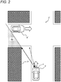
- FIG. 2 is a diagram exemplifying a situation different from FIG. 1 of a moving body in the present application example.
- the sensing device 1 can be applied to, for example, in-vehicle use, and constitutes a moving body system in a moving body such as an automobile.
- FIG. 1 exemplifies a traveling state of a vehicle 2 on which the sensing device 1 is mounted.
- the moving body system according to the present application example uses, for example, the sensing device 1 to monitor the surrounding environment that changes around the own vehicle 2 that is traveling.
- the surrounding environment includes, for example, structures such as a building and a utility pole existing around the own vehicle 2, and various objects such as moving objects such as a pedestrian and another vehicle.
- a wall 31 of a structure near an intersection 3 blocks a range that can be monitored from the own vehicle 2, and thus a blind spot occurs.
- the blind spot indicates a place that cannot be seen directly geometrically depending on the surrounding environment from a moving body such as the own vehicle 2.
- another vehicle 4 approaching an intersection 3 from a side road exists in the blind spot region R1 which is a region of the blind spot from the own vehicle 2.
- R1 is a region of the blind spot from the own vehicle 2.
- the sensing device 1 of the present embodiment detects an object existing in the blind spot region R1 (hereinafter, may be referred to as a "blind spot object") such as the vehicle 4, and determines a risk level based on a detection result of the blind spot object 4.
- the risk level relates to the possibility that the own vehicle 2 and the blind spot object 4 collide with each other, for example.
- the sensing device 1 can perform various control of driving support or driving control for warning to avoid a collision at the crossing or the like in accordance with a determination result of the risk level.
- FIG. 2 illustrates an example of a situation in which the positional relation between the own vehicle 2 and a blind spot is different from that of the intersection 3 in FIG. 1 , an intersection 3' having a wider distance between the wall 31 and a road, and a better view than the intersection 3.
- a vehicle 4' which has the same positional relation as the blind spot object 4 in FIG. 1 with the own vehicle 2, is located outside the blind spot region R1 in the present example, and can be visually recognized without detection of the inside of the blind spot.
- the distance from the own vehicle 2 to the blind spot is longer than that of the example of FIG. 1 .
- the sensing device 1 of the present embodiment controls the precision for detection in a blind spot according to the distance to the blind spot.
- the precision indicates what degree the sensing device 1 detects the blind spot object 4 precisely in the blind spot region R1 (hereinafter, also referred to as "sensing density").
- sensing density By controlling the sensing density in the sensing device 1, it is possible to reduce the processing load in a situation where there is a low possibility of a collision at the crossing and to efficiently detect the blind spot object 4. Further, excessive warnings and the like can be avoided, and the driving of the own vehicle 2 can be made smooth.
- FIG. 3 is a block diagram exemplifying the configuration of the present system.
- the present system includes the sensing device 1 and a vehicle control device 20.
- the sensing device 1 of the present embodiment includes a radar 11, a camera 12, and a controller 13.
- the sensing device 1 further includes a storage 14, a navigation device 15, and an in-vehicle sensor 16.
- the vehicle control device 20 includes various in-vehicle devices mounted on the own vehicle 2, and is used for driving support or automatic driving, for example.
- the radar 11 includes, for example, a transmitter 11a, a receiver 11b, and a radar control circuit 11c.
- the radar 11 is an example of a detector in the present embodiment.
- the radar 11 is installed on the front grill, the windshield, or the like of the own vehicle 2 so as to transmit and receive a signal toward the front (see FIG. 1 ) in the traveling direction of the own vehicle 2, for example.
- the transmitter 11a includes, for example, an antenna having variable directivity (phased array antenna or the like), a transmission circuit for causing the antenna to transmit the physical signal Sa to the outside, and the like.
- the physical signal Sa includes, for example, at least one of a millimeter wave, a microwave, a radio wave, and a terahertz wave.
- the physical signal Sa is an example of an output signal by the detector in the present embodiment.
- the receiver 11b includes, for example, an antenna having variable directivity, a receiving circuit for receiving the wave signal Sb from the outside by the antenna, and the like.
- the wave signal Sb is set in the same wavelength band as the physical signal Sa so as to include the reflected wave of the physical signal Sa.
- the transmitter 11a and the receiver 11b may use a shared antenna or may be integrally configured, for example.
- the radar control circuit 11c controls the transmitting and receiving of a signal by the transmitter 11a and the receiver 11b.
- the radar control circuit 11c starts transmitting and receiving of a signal by the radar 11 or controls the direction in which the physical signal Sa is radiated from the transmitter 11a, for example, by a control signal from the controller 13. Further, the radar control circuit 11c radiates the physical signal Sa from the transmitter 11a to scan a predetermined range such as the surrounding environment, and detects the wave signal Sb indicating the reflected wave of the physical signal Sa in a receiving result of the receiver 11b.
- the radar 11 operates according to a modulation system such as a continuous wave (CW) system or a pulse system, and measures the distance, direction, speed, and the like of an external object.
- a modulation system such as a continuous wave (CW) system or a pulse system
- the CW system includes a two-wave CW system, an FM-CW system, a spread spectrum system, and the like.
- the pulse system may be a pulse-Doppler system, or may use pulse compression of a chirp signal or pulse compression of a PN sequence.
- the radar 11 uses, for example, coherent phase information control.
- the radar 11 may use an incoherent system.
- the camera 12 is installed at a position where, for example, a range superimposed on a range in which the physical signal Sa can be radiated from the radar 11 in the own vehicle 2 can be imaged.
- the camera 12 is installed on the windshield or the like of the own vehicle 2 with an orientation frontward for the own vehicle 2, for example (see FIG. 1 ).
- the installation position of the camera 12 may be used as a geometrical reference or the installation position of the radar 11 may be used as a reference.
- the camera 12 captures an external image from the installation position and generates a captured image.
- the camera 12 outputs image data indicating the captured image to the controller 13.
- the camera 12 is, for example, an RGB-D camera, a stereo camera, or a distance image sensor.
- the camera 12 is an example of a distance measurer (or monitor) in the present embodiment.
- the controller 13 includes a CPU, a RAM, a ROM, and the like, and controls each constituent according to information processing.
- the controller 13 is composed of, for example, an electronic controller (ECU).
- the controller 13 loads a program stored in the storage 14 into a RAM, and the CPU interprets and executes the program loaded into the RAM.
- the controller 13 realizes a blind-spot-region estimator 131, a blind-spot-object measurer 132, and a risk-level determiner 133.
- Each of the modules 131 to 133 will be described later.
- the storage 14 stores a program executed by the controller 13, various data, and the like.
- the storage 14 stores structural information D1 described later.
- the storage 14 includes, for example, a hard disk drive or a solid state drive. Further, the RAM and the ROM may be included in the storage 14.
- the above programs and the like may be stored in a portable storage medium.
- the storage medium is a medium that stores information such as a program and the like by an electrical, magnetic, optical, mechanical, or chemical action so that a computer, other devices and machines can read the stored information of the program and the like.
- the sensing device 1 may acquire the program and the like from the storage medium.
- the navigation device 15 is an example of a distance measurer (or monitor) including, for example, a memory for storing map information and a GPS receiver.
- the in-vehicle sensor 16 is various sensors mounted on the own vehicle 2, and includes, e.g., a vehicle speed sensor, an acceleration sensor, a gyro sensor, and the like. The in-vehicle sensor 16 detects the speed, acceleration, angular velocity, and the like of the own vehicle 2.
- the sensing device 1 is not limited to the above configuration.
- the sensing device 1 does not have to include the navigation device 15 or the in-vehicle sensor 16.
- the controller 13 of the sensing device 1 may be composed of a plurality of hardware resources that separately execute each of the above units 131 to 133.
- the controller 13 may be composed of various semiconductor integrated circuits such as a CPU, an MPU, a GPU, a microcomputer, a DSP, an FPGA, and an ASIC.
- the vehicle control device 20 is an example of a control device of the moving body system according to the present embodiment.
- the vehicle control device 20 includes, for example, a vehicle driving device 21 and a notification device 22.
- the vehicle driving device 21 is composed of, for example, an ECU, and drives and controls each unit of the own vehicle 2.
- the vehicle driving device 21 controls the brake of the own vehicle 2 to realize automatic braking.
- the notification device 22 notifies the user of various information by means of an image, a sound, or the like.
- the notification device 22 is, for example, a display device such as a liquid crystal panel or an organic EL panel mounted on the own vehicle 2.
- the notification device 22 may be a voice output device that outputs an alarm or the like by voice.
- a detector may be configured by the cooperation of a radar 11 and a controller 13 (blind-spot-object measurer 132). Further, a distance measurer may also be configured in cooperation with the controller 13.
- the moving body system operates the sensing device 1 to monitor the surrounding environment, when the own vehicle 2 is driven, for example.
- the vehicle control device 20 of the present system performs various control for driving support, automatic driving, or the like of the own vehicle 2 based on the detection result by the sensing device 1.
- the sensing device 1 of the present embodiment captures an image around the own vehicle 2 with a camera 12 and monitors the surrounding environment of the own vehicle 2, for example.
- a blind-spot-region estimator 131 of the sensing device 1 in turn detects a region where a blind spot is estimated in the current surrounding environment, based on distance information indicating various distances in the monitoring result and the like, for example.
- the blind-spot-object measurer 132 measures an internal state of the blind spot region R1 using the radar 11. It is expected that the physical signal Sa radiated from the radar 11 of the own vehicle 2, which has a wave-like property, may generate the propagation in which the physical signal Sa causes multiple reflections, diffractions, or the like to reach the blind spot object 4 in the blind spot region R1, and further returns to the own vehicle 2.
- the sensing method of the present embodiment detects the blind spot object 4 by utilizing a wave propagating as described above.
- a risk-level determiner 133 of the present embodiment determines a risk level of the blind spot object 4 that may exist in the blind spot region R1 based on a measurement result of the blind-spot-object measurer 132.
- the risk level indicates the degree to which a collision between the blind spot object 4 and the own vehicle 2 is expected to be possible, for example.
- the present system can notify the driver or the like by the notification device 22 or execute vehicle control for enhancing the safety such as automatic braking by the vehicle driving device 21.
- the sensing device 1 of the present embodiment dynamically sets the sensing density, which is the precision when the radar 11 is made to perform the detection in the blind spot region R1 in the sensing method as described above.
- the details of the operation of the sensing device 1 in the present system will be described below.
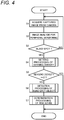
- FIG. 4 is a flowchart for describing the operation of the sensing device 1 according to the present embodiment. Each processing shown in the flowchart of FIG. 4 is executed by the controller 13 of the sensing device 1. The present flowchart is started at a predetermined cycle, for example, while the vehicle 2 is driven.
- the controller 13 acquires a captured image of one or more frames from the camera 12 (S1).
- the controller 13 may acquire a distance image as the captured image, or may generate a distance image based on the acquired captured image.
- the distance image is an example of distance information indicating various distances for monitoring the surrounding environment.
- the controller 13 performs various image analysis for peripheral monitoring on the acquired captured image (S2). For example, the controller 13 generates structural information D1 regarding the current surrounding environment of the own vehicle 2.
- the structural information D1 is information indicating various object structures in the surrounding environment, and includes distances to various structures, for example.
- the controller 13, operating as the blind-spot-region estimator 131 in step S2, performs detection of a blind spot by image analysis on the acquired captured image.
- FIG. 5 exemplifies an image to be analyzed in step S2.
- an image is captured from the own vehicle 2 as a distance image (S1), and the image shows walls 31 and 32 formed by a plurality of structures in the vicinity of the intersection 3.
- the blind spot region R1 exists on the back side of the wall 31 due to shielding by the wall 31 in the vicinity of the own vehicle 2.
- the wall 32 on the back side of the blind spot region R1 faces the own vehicle 2.
- the wall 31 is referred to as a "shielding wall”
- the wall 32 is referred to as a "facing wall”.
- a boundary between the blind spot region R1 and the outside is formed between the shielding wall 31 and the facing wall 32 (see FIG. 1 ).
- step S2 the controller 13 extracts distance values of the various walls 31 and 32 in the distance image as structural information D1 for each pixel and holds them in a storage 14.
- the distance value changes continuously from the side of the own vehicle 2 for the size of the shielding wall 31 along a direction d1, and changes discontinuously from an end portion (i.e., a blind spot end 31a ( FIG. 9 )) of the shielding wall 31 to the facing wall 32.
- the controller 13 can estimate the existence of the blind spot region R1 by analyzing the change in the distance value as described above.
- the controller 13 as the blind-spot-region estimator 131 determines whether or not the blind spot region R1 is detected in the current surrounding environment of the own vehicle 2 according to an estimation result by image analysis, for example (S3).
- the controller 13 periodically repeats the processing of steps S1 to S3, for example,.
- the controller 13 When determining that, the blind spot region R1 is detected (YES in S3), the controller 13 performs setting processing of the sensing density, for example (S4).
- the setting processing of the sensing density is processing of setting the sensing density in the detection in the blind spot region R1.
- the processing of step S4 sets the sensing density lower, as the distance to the blind spot end 31a is farther. The details of the processing in step S4 will be described later.
- the controller 13 executes detection processing of a blind spot object in the set sensing density (S6).
- the blind spot object 4 in the blind spot region R1 is detected by utilizing a multiple reflected wave in the wave signal Sb of the radar 11.
- step S6 the controller 13 radiates the physical signal Sa from the radar 11 in a manner scanning a range of the facing wall 32 and the like in the vicinity of the boundary of the blind spot region R1, based on the analysis result of FIG. 5 , for example.
- FIGS. 6a and 6b exemplify a propagation path of the physical signal Sa in step S6 in cases where there is and there is not the blind spot object 4, respectively.
- the physical signal Sa from the radar 11 of the own vehicle 2 is repeatedly reflected between the facing wall 32 and a wall 35 on the opposite side via the blind spot region R1 of a side road, and propagates as a multiple reflected wave.
- the multiple reflected wave does not come toward the own vehicle 2 corresponding to the absence of the blind spot object 4.
- the physical signal Sa from the radar 11 is reflected by the blind spot object 4 in addition to the walls 32 and 33, respectively, so as to be a multiple reflected wave Rb1 directed toward the own vehicle 2. Therefore, the wave signal Sb received by the radar 11 includes a signal component of the multiple reflected wave Rb1 having the information of the blind spot object 4.
- a signal component of the multiple reflected wave Rb1 ( FIG. 6b ) has information according to the speed of the blind spot object 4 as a reflection source and the length of the propagation path by the Doppler shift, the phase and the propagation time.
- the detection processing of a blind spot object detects the speed, position, and the like of the blind spot object 4 that reflects the multiple reflected wave Rb1. The details of the processing in step S6 will be described later.
- the controller 13 performs determination processing of a risk level based on a detection result (S6) of the blind spot object 4 (S7).
- a risk level is determined as the necessity of a warning regarding the detected blind spot object 4, and various control signals are output to a vehicle control device 20 according to a determination result, for example.
- the controller 13 When determining in step S7 that a warning is required, the controller 13 generates a control signal for causing a notification device 22 to notify the warning or controlling a vehicle driving device 21.
- the risk level may be determined using such information in step S7.
- the details of the processing in step S7 will be described later.
- the controller 13 When, outputting a control signal (S8), the controller 13 ends the processing shown in the flowchart of FIG. 4 , for example.
- step S4 the controller 13 ends the processing according to the present flowchart without performing the detection processing of a blind spot object (S6) or the like.
- the controller 13 executes the present flowchart again after a period of a predetermined cycle elapses, for example.
- the sensing device 1 detects the blind spot object 4 (S6) when a blind spot is found (YES in S3), so as to perform various actions according to a risk level (S7).
- S6 blind spot object 4
- S7 a risk level
- the farther the distance to the blind spot end 31a the lower the sensing density for the detection processing of a blind spot object (S6) is set (S4). Consequently, the processing efficiency of the sensing device 1 can be improved.
- the camera 12 is used for the peripheral monitoring.
- the navigation device 15 may be used.
- the present variation is shown in FIG. 7 .
- the navigation device 15 calculates various distances to the own vehicle 2 in map information D2 of the surrounding environment of the own vehicle 2 and monitors the current position of the own vehicle 2.
- the controller 13 can use the monitoring result of the navigation device 15 as described above for various processing shown in FIG. 4 .
- the controller 13 can acquire the structural information D1 and detect the blind spot region R1 based on the monitoring result of the navigation device 15, based on a structure 30 in the map information D2, for example (S2). Further, the controller 13 may appropriately use a detection result of the in-vehicle sensor 16 in the processing of FIG. 4 .
- the controller 13 may determine a risk level regarding the obstacle outside the blind spot and issue various warnings according to a determination result, for example.
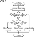
- FIG. 8 is a flowchart exemplifying the setting processing of the sensing density according to the present embodiment.
- FIG. 9 is a diagram for describing the setting processing of the sensing density according to the present embodiment. The processing by the flowchart of FIG. 8 is executed by the controller 13 in step S4 of FIG. 4 .
- the controller 13 calculates a distance to a blind spot regarding the blind spot detected in step S3 of FIG. 4 (S11).
- FIG. 9 exemplifies a blind spot direction d10 from the own vehicle 2 toward the blind spot end 31a, a traveling direction d11 of the own vehicle 2, and a crossing direction d12 orthogonal to the traveling direction d11.
- the controller 13 calculates a distance L in the blind spot direction d10 with reference to the blind spot end 31a based on the distance information obtained in steps S1 and S2 of FIG. 4 .
- the controller 13 determines whether or not the calculated distance L exceeds a preset upper limit value (S12).
- the upper limit value is a value indicating an upper limit of a range of the distance for which it is presumed that the blind spot object 4 needs to be detected from the possibility of collision between the blind spot object 4 and the own vehicle 2 (e.g., 120 m).
- the controller 13 When determining that the distance L exceeds the upper limit value (YES in S12), the controller 13 sets the sensing density to "0" (S13), and ends the processing of step S4 in FIG. 4 . In this case, the controller 13 proceeds to "YES” in subsequent step S5, and the detection processing of a blind spot object (S6) is omitted.
- the controller 13 sets the sensing density in a range higher than "0" (S14 to S16).
- S14 to S16 a processing example of setting the sensing density according to the distance L from two levels M1 and M2 will be described.
- the controller 13 determines whether or not the distance L exceeds a preset reference value (S14).
- the reference value is set at a positive value smaller than the above upper limit value in consideration of the necessity of precisely detecting the blind spot object 4 according to the distance L, for example.
- the controller 13 When determining that the distance L does not exceed the reference value (NO in S14), the controller 13 sets the sensing density to a standard level M2 (S15).
- the standard level M2 indicates the standard sensing density for detecting the blind spot object 4 precisely.
- the controller 13 sets the sensing density to a low level M1 (S16).
- the low level M1 indicates a lower sensing density than standard level M2.
- the controller 13 ends the processing of Step S4 in FIG. 4 .
- the controller 13 proceeds to "NO" in subsequent step S5, and executes the detection processing of a blind spot object (S6).
- the sensing density for detecting the blind spot object 4 is dynamically controlled according to the distance L from the own vehicle 2 to a blind spot. Further, in a case where the distance L is sufficiently large, detection of the blind spot object 4 is controlled not to be performed. In this manner, the processing efficiency of the sensing device 1 can be improved.
- the example (S14 to S16) is described in which the sensing density is set in the two levels M1 and M2, but not limited to this.
- the sensing density may be set in three or more levels.
- the controller 13 may use a level higher than the standard level according to a case where the distance L is small. Further, the sensing density may be set as a continuous value. The controller 13 may calculate the sensing density based on the distance L sequentially.
- the example is described in which the sensing density is set using the distance L in the blind spot direction d10.
- the sensing density setting processing of the present embodiment is not limited to this, and for example, the distance L2 in the crossing direction d12 may be used.
- the traveling direction d11 and the blind spot direction d10 of the own vehicle 2 form an angle ⁇ .
- the distance L in the blind spot direction d10 can be orthogonally decomposed into a distance L1 in the traveling direction d11 and a distance L2 in the crossing direction d12.
- the controller 13 can calculate the respective distances L1 and L2 and the angle ⁇ together with or separately from the distance L by acquiring the traveling direction d11 of the own vehicle 2 from the in-vehicle sensor 16, for example (S11).
- the controller 13 may set the magnitude of the sensing density by using the distance L2 of the crossing direction d12 instead of the distance L of the blind spot direction d10, for example.
- the controller 13 sets the sensing density smaller as the distance L2 in the crossing direction d12 is larger (S14, S16). In this manner as well, the processing efficiency of the sensing device 1 can be improved.
- the sensing density may be set using both the distances L and L2.
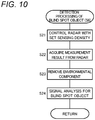
- FIG. 10 is a flowchart exemplifying the detection processing of a blind spot object according to the present embodiment.
- FIG. 11 is a diagram for describing the detection processing of a blind spot object.
- the processing according to the flowchart of FIG. 10 is executed by the controller 13 that operates as the blind-spot-object measurer 132 in step S6 of FIG. 4 .
- the controller 13 as the blind-spot-object measurer 132 controls the radar 11 to radiate the physical signal Sa to the blind spot region R1 (S21). For example, as the sensing density is higher, the controller 13 controls the radar 11 to shorten the time interval in which the radiation of the physical signal Sa is repeated for scanning or re-measurement more.
- step S21 the radar 11 radiates the physical signal Sa and receives the wave signal Sb to perform various measurement based on the reflected wave of the physical signal Sa.
- the controller 13 acquires a measurement result from the radar 11 (S22).
- the controller 13 removes an environmental component showing a reflected wave from the surrounding environment from the acquired measurement result of the radar 11, to extract a signal component for analyzing the blind spot object (S23).
- the processing of step S23 is performed using the structural information D1 acquired in step S2 for example,.
- the controller 13 predicts a reflected wave due to direct reflection from various structures around the intersection 3, and subtracts a predicted environmental component from the measurement outcome of the radar 11, for example (S23). According to this, the influence of the reflected wave by the structure under an environment can be reduced, and it can be facilitated to obtain only the signal component of the object in the blind spot.
- the controller 13 performs signal analysis for detecting the blind spot object 4 based on the signal component obtained by removing the environmental component (S24).
- the signal analysis in step S24 may include various analysis such as frequency analysis, analysis on the time axis, spatial distribution, and signal strength.
- step S24 the controller 13 determines the presence or absence of the blind spot object 4 by analyzing whether or not a wave source is observed on the further side of the blind spot (facing wall 32) under the assumption that a propagation path of a wave is linear, for example.
- a wave source 40 of the multiple reflected wave from the blind spot object 4 is observed to be on the further side than the facing wall 32 in the example of FIG. 11 .
- the wave source 40 is at a position not predicted as an environmental component from the structural information D1. It can be expected that such a situation is caused by the multiple reflection of a wave from the object 4 in the blind spot. That is, the controller 13 can determine that the blind spot object 4 is present in a case where a reflected wave is observed at a distance exceeding the facing wall 32 in the direction of the detected blind spot.
- the controller 13 can calculate various measured values such as the distance to the blind spot object 4 and its speed, according to the propagation path in which refraction is predicted due to multiple reflections, for example. For example, by using information indicating a road width of the blind spot portion (width of the blind spot region R1) in the structural information D1, the controller 13 can calculate the position of the blind spot object 4 closer to the actual position with correction of a path length to the blind spot object 4, which is found from the signal component, in a manner folding back the path as exemplified in FIG. 11 .
- the controller 13 After the signal analysis (S24) of the blind spot object 4, the controller 13 ends the process of step S6 of FIG. 4 . After that, the controller 13 executes the determination processing of a risk level (S7 in FIG. 4 ) for the blind spot object 4 for which signal analysis is performed.
- the blind spot object 4 can be detected by using a signal component generated inside the blind spot region R1, based on the property of multiple reflections in the physical signal Sa of the radar 11.
- step S21 the controller 13 controls the radar 11 according to the set sensing density. Accordingly, in a case where the sensing density is set to the low level M1 (S16 in FIG. 8 ), the processing load can be reduced as compared with the case of the standard level M2 (S15), for example. Thus, the blind spot object 4 can be detected efficiently.
- the control according to the sensing density in step S21 is not limited to the above, and various control may be performed.
- the controller 13 may increase the magnitude of output (i.e., the magnitude of the output signal) of the physical signal Sa radiated from the radar 11, or sharpen the directivity of radiation of the physical signal Sa as the sensing density increases.
- the directivity it is possible to improve the substantial output for detecting the inside of a blind spot and to suppress a component that undergoes excessive multiple reflections.
- the controller 13 may widen a frequency band of the physical signal Sa or lengthen a signal length of the physical signal Sa as the sensing density increases. According to the control of the frequency band, the time resolution in a received wave can be improved, for example. Controlling the signal length can improve the frequency resolution for analyzing the Doppler shift.
- the controller 13 may remove a signal component of a received wave obtained in the reciprocating propagation time of a signal or less, with respect to a linear distance from the intersection.
- a received wave is a directly reflected wave (i.e., a wave with one reflection) and does not include information on the blind spot object 4. Thus, is can be excluded from the object to be analyzed.
- the controller 13 can separate a reflected wave arriving from the blind spot and a reflected wave arriving from another angle, based on an azimuth angle of the blind spot from the own vehicle 2.
- step S23 does not need to use the structural information D1 of the surrounding environment.
- the controller 13 may restrict the object to be analyzed to a moving object, by subtracting a position change of the own vehicle 2 from a signal obtained along the time axis.
- the present processing may be performed in the signal analysis in step S24.
- the controller 13 may analyze whether or not to find a characteristic that appears due to the behavior of a specific object, e.g., Doppler shift due to reflection on a moving object or fluctuation of the behavior peculiar to a person or a bicycle in the signal component to be analyzed. Further, the controller 13 may analyze whether area-measured signal distribution with spatial expanse has distribution peculiar to an automobile, a bicycle, a person or the like, or includes reflection by an automobile-sized metal body based on reflection intensity, or the like. The above analysis may be performed in combination as appropriate, or may be performed as a multidimensional feature quantity using machine learning instead of explicitly analyzing each.
- a characteristic that appears due to the behavior of a specific object e.g., Doppler shift due to reflection on a moving object or fluctuation of the behavior peculiar to a person or a bicycle in the signal component to be analyzed. Further, the controller 13 may analyze whether area-measured signal distribution with spatial expanse has distribution peculiar to an automobile, a bicycle, a person or the like, or includes reflection by an
- FIG. 12 is a flowchart exemplifying the determination processing of a risk level.
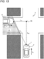
- FIG. 13 is a diagram for describing the determination processing of a risk level. The processing according to the flowchart of FIG. 12 is executed by the controller 13 that operates as the risk-level determiner 133 in step S7 of FIG. 4 .
- the controller 13 calculates a risk level index D based on the detection result of the blind spot object 4 in step S6 (S31).
- the risk level index D indicates an index for determining a risk level of collision between the detected blind spot object 4 and the own vehicle 2.
- the speed v 1 at which the blind spot object 4 approaches the own vehicle 2 can be set as the risk level index D.
- the controller 13 determines whether or not the calculated risk level index D exceeds the threshold value Va, for example (S32).
- the controller 13 When determining that the risk level index D exceeds the threshold value Va (YES in S32), the controller 13 performs various warning control as a result of determining the risk level at which a warning is required (S33).
- the warning control includes output of a control signal for causing the notification device 22 to issue a warning or the vehicle driving device 21 to perform specific control.
- the controller 13 ends the determination processing of the risk level (S7 in FIG. 4 ) by performing the warning control (S33).
- the controller 13 when determining that the risk index D does not exceed the threshold value Va (NO in S32), the controller 13 ends step S7 in FIG. 4 without particularly performing the warning control (S33), as a result of determining that no warning is required. Then, the controller 13 executes the flowchart of FIG. 4 again, for example.
- a risk level of the blind spot object 4 approaching the own vehicle 2 or the intersection 3 is determined according to the corresponding risk level index D. For example, binary determination is performed according to the necessity of a warning.
- the determination processing of a risk level is not limited to the binary determination, and for example, a ternary determination may be performed for determining whether or not attention calling in a case where a warning is unnecessary. For example, using a threshold value Vb ( ⁇ Va) for attention calling, the controller 13 may determine whether or not D > Vb when proceeding to "NO" in step S32.
- the risk level index D is not limited to the speed v 1 , and can be set by (measured values of) various quantities related to the blind spot object 4.
- the risk level index D may be set to an acceleration dv 1 /dt instead of the speed v 1 .
- the risk level index D may be set to a distance L h between the own vehicle 2 and the blind spot object 4. It is presumed that as the distance L h is smaller, the risk level of collision between the own vehicle 2 and the blind spot object 4 is higher.
- the risk level index D may be set by a combination of various quantities.
- L h1 is a distance from a reference position P0 to the blind spot object 4 ( FIG. 12 ).
- the reference position P0 is set to a position where collision between the blind spot object 4 and the own vehicle 2 is expected, such as the center of an intersection.
- the predetermined time width ⁇ t is set in the vicinity of a time width that the own vehicle 2 is predicted to take to reach the reference position P0.
- the distance L h0 is a distance from the reference position P0 to the own vehicle 2.
- the speed v 0 of the own vehicle 2 can be acquired from the in-vehicle sensor 16 and the like.
- the risk level index D in the above equation (1) is the sum of a distance between the blind spot object 4 and the reference position P0 and a distance between the reference position P0 and the own vehicle 2 estimated after the time width ⁇ t elapses ( FIG. 12 ). According to the above equation (1), it can be estimated that when the risk level index D is smaller than a predetermined value, the possibility that the own vehicle 2 and the blind spot object 4 reach the reference position P0 at the same time is sufficiently high.
- ⁇ t L h0 /v 0 is set for example.
- the time width ⁇ t may be set within an allowable range in consideration of a fluctuation of the speed v 0 of the own vehicle 2 or an estimation error of the reference position P0.
- the controller 13 can use the risk level index D of the equation (2) or the equation (2') to determine a risk level as in the case of the equation (1) .
- the threshold value Va may be dynamically changed according to states of the own vehicle 2 and the blind spot object 4. For example, in a case where L h0 described above is small, dv 0 /dt or dv 1/ dt is large, or the blind spot object 4 is estimated to be a person, it is considered that the determination of a risk level should be performed more strictly. In view of the above, when such a case is detected, the controller 13 may increase the threshold value Va with respect to the risk level index D of the above equation (1), for example.
- the sensing device 1 detects an object in a blind spot, that is the blind spot object 4, in the surrounding environment of the own vehicle 2 which is an example of a moving body.
- the sensing device 1 includes the camera 12 as a distance measurer, the radar 11 as a detector, and the controller 13.
- the camera 12 acquires distance information indicating a distance from the own vehicle 2 to the surrounding environment.
- the radar 11 detects an object in a blind spot.
- the controller 13 controls operation of the radar 11.
- the controller 13 detects a blind spot in the surrounding environment, based on the acquired distance information (S3).
- the controller 13 controls the precision at which the detector detects an object in the blind spot, that is, the sensing density, in accordance with the distance to the blind spot (S4).
- the above sensing device 1 by controlling the sensing density according to the condition information related to the distance to the blind spot, it is possible to efficiently detect an object in a blind spot in the surrounding environment of the own vehicle 2.
- the controller 13 sets the sensing density to be smaller (S14 to S16).
- the inside of the blind spot can be detected efficiently with the processing load being reduced.
- the controller 13 may set the sensing density smaller as the distance L2 between the own vehicle 2 and the blind spot in the crossing direction d12 is larger.
- the controller 13 controls the radar 11 so as not to detect the blind spot object 4 when the distance L to the blind spot is larger than a predetermined upper limit value (S12 to S13). In this manner, in a situation where the possibility of a collision between the blind spot object 4 and the own vehicle 2 is expected to be sufficiently small, the detection of the blind spot object 4 can be omitted and the processing efficiency can be improved.
- the radar 11 radiates the physical signal Sa as an output signal having a wave characteristic from the own vehicle 2 to the surrounding environment, and the blind spot object 4 is detected based on a component of a wave arriving from the blind spot in the reflected wave of the radiated physical signal Sa.
- a wave characteristic of the physical signal Sa from the radar 11 can be utilized to detect an object existing in a blind spot in the surrounding environment from the own vehicle 2.
- the wave to be utilized is not limited to a multiple reflected wave, and may include a diffracted wave or a transmitted wave.
- the sensing density is set corresponding to at least one of magnitude, time interval, directivity, frequency band, and signal length of the output signal of the radar 11 (S21). Reduction in the processing load can be achieved by control of various parameters of the radar 11 according to the sensing density.
- the controller 13 may control the radar 11 to radiate the physical signal Sa toward the detected blind spot region R1 (S21).
- the physical signal Sa can be concentrated in the vicinity of the blind spot region R1, and the multiple reflected waves Rb1 and the like can be easily obtained from the blind spot object 4 in the blind spot region R1.
- the physical signal Sa from the radar 11 does not need to be concentrated in the blind spot region R1.
- the physical signal Sa may be radiated in a range that can be detected by the radar 11 in a timely manner.
- the sensing device 1 of the present embodiment may further include the storage 14 that stores structural information D1 indicating an object structure of the surrounding environment.
- the controller 13 may analyze a wave signal including a component of a wave arriving from the blind spot region R1 in the detection result of the radar 11. By using the structural information D1, the detection of the blind spot object 4 can be made accurate.
- the controller 13 may generate the structural information D1 based on the detection result of the camera 12 and hold the structural information D1 in the storage 14 (S2).
- the structural information D1 can be generated sequentially so that the blind spot object 4 can be detected with high accuracy.
- the moving body system includes the sensing device 1 and the vehicle control device 20.
- the vehicle control device 20 is mounted on the own vehicle 2 and executes operation according to the detection result of the blind spot object 4 by the sensing device 1.
- the sensing device 1 can efficiently detect an object in a blind spot in the surrounding environment of the own vehicle 2.
- the sending method is a method of detecting an object in a blind spot in the surrounding environment of a moving body such as the own vehicle 2.
- the present method includes step S1 in which the distance measurer acquires distance information indicating a distance from the moving body to the surrounding environment, and steps S2 and S3 in which the controller 13 detects a blind spot in the surrounding environment based on the distance information.
- the present method includes step S4 in which the controller 13 controls the sensing density in which the detector is caused to detect an object in the blind spot according to the distance to the blind spot, and step S6 in which the detector detects an object in the blind spot in the sensing density.
- a program for causing the controller 13 to execute the above sensing method is provided. According to the sensing method of the present embodiment, it is possible to efficiently detect an object existing in a blind spot in the surrounding environment of a moving body such as the own vehicle 2.
- the operation example is described in which the sensing density is controlled using the distance L.
- operation of the sensing device 1 that controls the sensing density by using the speed of the own vehicle 2 will be further described.
- FIG. 16 is a flowchart exemplifying the setting processing of the sensing density according to a second embodiment.
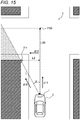
- FIG. 15 is a diagram for describing the setting processing of the sensing density according to the present embodiment.
- the controller 13 acquires a speed v 0 of the own vehicle 2 from the in-vehicle sensor 16 (S17a), and calculates a braking distance La by the following equation (20), for example (S17b).
- La v 0 2 / 2 ⁇ g ⁇ ⁇
- the friction coefficient ⁇ indicates the friction between a tire of the own vehicle 2 and the road surface 3a.
- predetermined value may be used, or the friction coefficient ⁇ may be calculated in real time.
- the controller 13 can calculate the friction coefficient ⁇ based on the detection result of the in-vehicle sensor 16 or the like.
- the controller 13 calculates a predicted position P20 at which the moving object is predicted to collide with the own vehicle 2 (S17c), and calculates a predicted distance L20 from the own vehicle 2 to the predicted position P20 (S17d). For example, the controller 13 can calculate the predicted position P20 and the predicted distance L20 based on the structural information D1 acquired in real time.
- the controller 13 determines whether or not the predicted distance L20 exceeds the braking distance La, for example (S17). When the predicted distance L20 exceeds the braking distance La, the own vehicle 2 can stop before reaching the predicted position P20. In view of the above, when determining that the predicted distance L20 exceeds the braking distance La (YES in S17), the controller 13 sets the sensing density to be smaller than that in the case of "NO", for example (S16). At this time, the controller 13 may set the sensing density to "0" and control the detection in a blind spot not to be performed.
- the sensing device 1 of the present embodiment further includes the in-vehicle sensor 16 which is an example of a speed receiver.
- the in-vehicle sensor 16 acquires the speed v 0 of the own vehicle 2.
- the controller 13 sets the sensing density based on the braking distance La of the own vehicle 2 according to the speed v 0 and the distance to the blind spot. In this manner, the inside of the blind spot is detected in consideration of the braking distance La of the own vehicle 2, and the safety can be improved.
- the operation of the sensing device 1 that detects a plurality of blind spots and controls the sensing density for detection in each of the blind spots will be described.
- FIG. 16 is a flowchart for describing the operation of the sensing device 1 according to the third embodiment.
- the controller 13 executes the flowchart of FIG. 16 instead of the flowchart of FIG. 4 .
- the controller 13 can detect a plurality of blind spots (S3).
- the controller 13 selects one blind spot in order from a blind spot having a shorter distance L , for example (S41) . With respect to the selected blind spot, the controller 13 performs the processing of Steps S4 to S7 in the same manner as described above. When warning control is performed in Step S7 (YES in S7b), the present processing ends.
- the sensing device 1 performs detection of the inside of a blind spot and the like (S4 to S7), by using the radar 11 at each sensing density in order from blind spots having a shorter distance L (S41).
- a risk level of the detected blind spot is low to the extent that no warning is required (NO in S7b)
- detection is performed for a blind spot with a next shortest distance L (S42 and S41).
- the controller 13 when a plurality of blind spots are detected, the controller 13 gives priority to a closer blind spot among a plurality of the blind spots and causes the radar 11 to detect an object in the blind spot (S41 to S42). In this manner, it is possible to efficiently detect the inside of a plurality of blind spots.
- the distance L is used in the setting processing ( FIG. 8 ) of the sensing density. Furthermore, the angle ⁇ (see FIG. 9 ) between the traveling direction d11 and the blind spot direction d10 of the own vehicle 2 may be used.
- FIG. 17 is a flowchart exemplifying the setting processing of the sensing density according to the present variation.
- the distance L in the blind spot direction d10 is constant and the above angle ⁇ is different, as the angle ⁇ is larger, the distance L1 in the traveling direction d11 is smaller while the distance L2 in the crossing direction d12 becomes is larger. At this time, the blind spot region R1 moves away in the crossing direction d12. Thus, it is considered that attention should be paid to the extension line of the traveling direction d11 from the own vehicle 2 rather than the inside of the blind spot region R1.
- the controller 13 determines whether or not the angle ⁇ exceeds a predetermined angle (S18), in addition to processing same as that in the first embodiment ( FIG. 8 ).
- the predetermined angle is an angle indicating the standard for the necessity of detection in the inside of a blind spot, and can be set to various angles such as 45°.
- the controller 13 sets the sensing density to "0" (S13), and the subsequent detection processing (S6 in FIG. 4 ) for a blind spot object can be omitted.
- the processing of the present variation is not limited to this.
- the controller 13 may set the sensing density to be smaller by various methods as the angle ⁇ is larger.
- the controller 13 may set the sensing density based on the angle ⁇ between the traveling direction d11 of the own vehicle 2 and the direction d11 from the own vehicle 2 toward a blind spot, and the distance L to the blind spot (S18). This also makes it possible for the sensing device 1 to efficiently detect the inside of a blind spot.
- the multiple reflected wave is utilized for detecting the blind spot object 4.
- the wave is not limited to the multiple reflected wave, and for example, a diffracted wave may be utilized.
- the reflected wave of the blind spot object 4 is diffracted at the blind spot end 31a and returns to the own vehicle 2 as a diffracted wave.
- the controller 13 of the present embodiment controls the wavelength and direction of the physical signal Sa radiated from the radar 11 so as to cause wraparound at the blind spot end 31a, for example.
- the signal can be allowed to reach even a region which cannot be geometrically reached by visible light having high straightness and the like due to the existence of various shielding objects.
- the signal since a vehicle, a person, and the like that can be the blind spot object 4 usually have a rounded shape, the signal is reflected not only to a completely reflexive path, but also in the direction in which the own vehicle 2, from which the signal is radiated, exists.
- the radar 11 can receive the diffracted wave as a signal component to be analyzed.
- the signal component of the diffracted wave has information on the propagation path to the blind spot object 4 and Doppler information according to the moving speed. Therefore, as signal analysis is performed on the signal component, the position and speed of the blind spot object 4 can be measured from the information on the propagation time, phase, and frequency of the signal component, as in the first embodiment. At this time, the propagation path of the diffracted wave can also be estimated from the distance to the blind spot end 31a or various the structural information D1. Further, the propagation path in which multiple reflection and diffraction are combined can also be estimated as appropriate, and the signal component of such a wave may be analyzed.
- the example is described in which the detector and the distance measurer are separately configured by the radar 11 and the camera 12 or the like.
- the detector and the distance measurer may be integrally configured.
- the sensing device 1 of the present variation uses the radar 11 to perform peripheral monitoring similar to that in S1 to S3 in FIG. 4 .
- the controller 13 may perform switching control of the band of the radar 11, to use a band that allows wraparound to likely occur at the blind spot, for example.
- the radar 11, the camera 12, and the navigation device 15 are described as examples of the detector and the distance measurer.
- the detector of the present embodiment is not limited to these, and for example, the detector or the distance measurer may be LIDAR.
- the physical signal Sa radiated from the detector may be an infrared ray, for example.
- the detector or the distance measurer may be sonar, or may radiate an ultrasonic wave as the physical signal Sa. In these cases, the wave signal Sb received by the detector is set in the same manner as the corresponding physical signal Sa.
- the example is described in which the radar 11 and the camera 12 are installed with the orientation frontward for the own vehicle 2.
- the installation position of the radar 11 and the like is not particularly limited.
- the radar 11 and the like may be installed with an orientation rearward for the own vehicle 2, and e.g., the moving body system may be used for parking assistance.
- the number of the radars 11 is not particularly limited, and may be provided on both sides of the own vehicle 2, for example.
- each of a plurality of the radars 11 may be used to detect the inside of different blind spots.
- the sensing device 1 detects the blind spot object 4 by utilizing the characteristics of the wave by the physical signal Sa.
- the method of detecting the blind spot object 4 is not necessarily limited to the above method, and various methods may be employed.
- the object 4 in the blind spot region R1 may be estimated based on various information. Even in this case, the processing efficiency can be improved by controlling the density according to the distance to a blind spot.
- an automobile is exemplified as an example of the moving body.
- the moving body on which the sensing device 1 is mounted is not particularly limited to an automobile, and may be, e.g., an AGV, a service robot or a drone.
- the sensing device 1 may detect an object in a blind spot by monitoring the surroundings during the automatic traveling of the AGV.
- a first aspect according to the present disclosure is a sensing device (1) for detecting an object in a blind spot in a surrounding environment of a moving body.
- the sensing device includes a distance measurer (12), a detector (11), and a controller (13).
- the distance measurer is configured to acquire distance information indicating a distance from the moving body to the surrounding environment.
- the detector is configured to detect the object in the blind spot.
- the controller is configured to control operation of the detector.
- the controller is configured to detect the blind spot in the surrounding environment, based on the distance information acquired by the distance measurer (S3).
- the controller is configured to control precision at which the detector is caused to detect the object in the blind spot, according to a distance to the blind spot (S4).
- the controller is configured to set the precision to be lower as the distance to the blind spot is larger (S14 to S16).
- the controller is configured to control the detector not to detect the object in the blind spot in a case where the distance to the blind spot is larger than a predetermined value (S12 to S13).
- the controller is configured to set the precision to be lower as a distance between the moving body and the blind spot in a direction (d12) orthogonal to a traveling direction of the moving body is larger.
- the sensing device further includes a speed receiver (S16) configured to acquire a speed of the moving body.
- the controller is configured to set the precision based on a braking distance (La) of the moving body according to the speed and the distance to the blind spot (S17).
- the controller is configured to set the precision based on an angle between a traveling direction of the moving body and a direction from the moving body toward the blind spot, and the distance to the blind spot (S18).
- the controller in a case where a plurality of blind spots being detected, is configured to cause the detector to detect the object in the blind spots with a closer blind spot among the plurality of blind spots being prioritized (S41 to S42).
- the detector is configured to: radiate an output signal having a wave characteristic from the moving body to the blind spot; and detect the object in the blind spot based on a component of a wave arriving from the blind spot in a reflected wave of a radiated output signal.
- the precision is set according to at least one of magnitude, a time interval, directivity, a frequency band, and a signal length of the output signal of the detector.
- a tenth aspect according to the present disclosure is a moving body system including: the sensing device according to any one of the first to ninth aspects; and a control device (20).
- the control device is arranged on the moving body to execute operation according to a detection result of the object in the blind spot by the sensing device.
- An eleventh aspect according to the present disclosure is a sensing method of detecting an object in a blind spot in a surrounding environment of a moving body (2) .
- the sensing method includes: acquiring (S1), by a distance measurer (12), distance information indicating a distance from the moving body to the surrounding environment; and detecting (S2, S3), by a controller (13), the blind spot in the surrounding environment, based on the distance information.
- the present method includes: controlling (S4), by the controller, precision at which a detector is caused to detect an object in the blind spot, according to a distance to the blind spot; and detecting (S6), by the detector (11), the object in the blind spot at the precision.
- a twelfth aspect according to the present disclosure is a program for causing a controller to execute the sensing method according to the eleventh aspect.
Landscapes
- Engineering & Computer Science (AREA)
- Radar, Positioning & Navigation (AREA)
- Remote Sensing (AREA)
- Physics & Mathematics (AREA)
- General Physics & Mathematics (AREA)
- Computer Networks & Wireless Communication (AREA)
- Electromagnetism (AREA)
- Traffic Control Systems (AREA)
Abstract
Description
- The present disclosure relates to a sensing device that detects a peripheral object from a moving body, a moving body system including the sensing device, and a sensing method.
- A technique that is mounted on a moving body such as an automobile or an automated guided vehicle (AGV) for monitoring the periphery of the moving body has been proposed (e.g., Patent Documents 1 and 2).
- Patent Document 1 discloses an obstacle recognition device that recognizes an obstacle in front of an own vehicle. The obstacle recognition device of Patent Document 1 includes a camera and a radar, detects a blind spot region for an own vehicle, and estimates the attribute of an obstacle that may exist in the blind spot region based on the size of the detected blind spot region. The obstacle recognition device causes the camera to search the blind spot region when it is estimated that the attribute of the obstacle that may exist in the blind spot region is a pedestrian, and causes the radar to search the blind spot region when it is estimated that the attribute of the obstacle is another vehicle.
-
Patent Document 2 discloses a vehicle environment estimation device for the purpose of accurately estimating a traveling environment around an own vehicle. The vehicle environment estimation device ofPatent Document 2 detects the behavior of other vehicles around the own vehicle, and estimates, based on the behavior of the vehicles, the existence of another vehicle traveling in a blind spot region from the own vehicle. In this way, a vehicle traveling environment that cannot be recognized by the own vehicle and can be recognized by other vehicles on the periphery is estimated. -
- Patent Document 1:
JP 2011-242860 A - Patent Document 2:
JP 2010-267211 A - In Patent Document 1, prior to the search in a blind spot region by the camera or the like, it is estimated whether an object that may exist in the region is a pedestrian or another vehicle based on the size of the region. In
Patent Document 2, the inside of a blind spot region is estimated based on a detection result around an own vehicle. However, they do not estimate whether the situation needs to detect the inside of a blind spot in the first place, or whether the necessity is high or low. Thus, in the prior art, efficiently performing the detection of an object in a blind spot according to a situation is difficult. - An object of the present disclosure is to provide a sensing device, a sensing method, and a moving body system capable of efficiently detecting an object in a blind spot in a surrounding environment of a moving body.
- A sensing device according to an aspect of the present disclosure is for detecting an object in a blind spot in a surrounding environment of a moving body. The sensing device includes a distance measurer, a detector, and a controller. The distance measurer is configured to acquire distance information indicating a distance from the moving body to the surrounding environment. The detector is configured to detect the object in the blind spot. The controller is configured to control operation of the detector. The controller is configured to detect the blind spot in the surrounding environment, based on the distance information acquired by the distance measurer. The controller is configured to control precision at which the detector is caused to detect the object in the blind spot, according to a distance to the detected blind spot.
- A moving body system according to an aspect of the present disclosure includes: the sensing device according; and a control device arranged on the moving body to execute operation according to a detection result of the object in the blind spot by the sensing device.
- A sensing method according to an aspect of the present disclosure is a sensing method of detecting an object in a blind spot in a surrounding environment of a moving body. The sensing method includes: acquiring, by a distance measurer, distance information indicating a distance from the moving body to the surrounding environment; and detecting, by a controller, the blind spot in the surrounding environment, based on the distance information. The present method includes: controlling, by the controller, precision at which a detector is caused to detect an object in the blind spot, according to a distance to the detected blind spot; and detecting, by the detector, the object in the blind spot at the precision.
- The sensing device, the sensing method, and the moving body system according to the present disclosure is capable of efficiently detecting an object in a blind spot in a surrounding environment of a moving body.
-
-
FIG. 1 is a diagram for describing an application example of a sensing device according to the present disclosure. -
FIG. 2 is a diagram exemplifying a situation different fromFIG. 1 of a moving body in the application example of the sensing device. -
FIG. 3 is a block diagram exemplifying a configuration of a moving body system according to a first embodiment of the present disclosure. -
FIG. 4 is a flowchart for describing operation of the sensing device according to the first embodiment. -
FIG. 5 is a diagram for describing an example of distance information in the sensing device. -
FIGS. 6a and 6b are diagrams for describing the operation of the sensing device according to the first embodiment. -
FIG. 7 is a diagram for describing a variation of the distance information in the sensing device. -
FIG. 8 is a flowchart exemplifying a setting processing of a sensing density according to the first embodiment. -
FIG. 9 is a diagram for describing the setting processing of the sensing density according to the first embodiment. -
FIG. 10 is a flowchart exemplifying the detection processing of a blind spot object by the sensing device. -
FIG. 11 is a diagram for describing the detection processing of a blind spot object by the sensing device. -
FIG. 12 is a flowchart exemplifying determination processing of a risk level by the sensing device. -
FIG. 13 is a diagram for describing determination processing of a risk level by the sensing device. -
FIG. 14 is a flowchart exemplifying a setting processing of a sensing density according to a second embodiment. -
FIG. 15 is a diagram for describing the setting processing of the sensing density according to the second embodiment. -
FIG. 16 is a flowchart for describing operation of the sensing device according to a third embodiment. -
FIG. 17 is a flowchart exemplifying a setting processing of a sensing density according to a modification of the first embodiment. - Hereinafter, embodiments of the sensing device and method, and the moving body system according to the present disclosure will be described with reference to the accompanying drawings. Note that, in each of the embodiments below, the same reference numerals are given to the same constituents.
- An example to which the sensing device and method, and the moving body system according to the present disclosure can be applied will be described with reference to
FIGS. 1 and2 .FIG. 1 is a diagram for describing an application example of the sensing device 1 according to the present disclosure.FIG. 2 is a diagram exemplifying a situation different fromFIG. 1 of a moving body in the present application example. - The sensing device 1 according to the present disclosure can be applied to, for example, in-vehicle use, and constitutes a moving body system in a moving body such as an automobile.
FIG. 1 exemplifies a traveling state of avehicle 2 on which the sensing device 1 is mounted. The moving body system according to the present application example uses, for example, the sensing device 1 to monitor the surrounding environment that changes around theown vehicle 2 that is traveling. The surrounding environment includes, for example, structures such as a building and a utility pole existing around theown vehicle 2, and various objects such as moving objects such as a pedestrian and another vehicle. - In the example of
FIG. 1 , awall 31 of a structure near anintersection 3 blocks a range that can be monitored from theown vehicle 2, and thus a blind spot occurs. The blind spot indicates a place that cannot be seen directly geometrically depending on the surrounding environment from a moving body such as theown vehicle 2. In the present example, anothervehicle 4 approaching anintersection 3 from a side road exists in the blind spot region R1 which is a region of the blind spot from theown vehicle 2. In the above case, it is concerned that thevehicle 4 from a blind spot and theown vehicle 2 might collide with each other at the crossing. - In view of the above, the sensing device 1 of the present embodiment detects an object existing in the blind spot region R1 (hereinafter, may be referred to as a "blind spot object") such as the
vehicle 4, and determines a risk level based on a detection result of theblind spot object 4. The risk level relates to the possibility that theown vehicle 2 and theblind spot object 4 collide with each other, for example. The sensing device 1 can perform various control of driving support or driving control for warning to avoid a collision at the crossing or the like in accordance with a determination result of the risk level. -
FIG. 2 illustrates an example of a situation in which the positional relation between theown vehicle 2 and a blind spot is different from that of theintersection 3 inFIG. 1 , an intersection 3' having a wider distance between thewall 31 and a road, and a better view than theintersection 3. For example, a vehicle 4', which has the same positional relation as theblind spot object 4 inFIG. 1 with theown vehicle 2, is located outside the blind spot region R1 in the present example, and can be visually recognized without detection of the inside of the blind spot. - In the example of
FIG. 2 , the distance from theown vehicle 2 to the blind spot is longer than that of the example ofFIG. 1 . Owing to the far blind spot from theown vehicle 2, even when an object exists in the blind spot (inside the blind spot region R1), a case is expected where the possibility for the object to collide with theown vehicle 2 is sufficiently low. If, even in such a case, the detection of the inside of the blind spot is executed with the same precision as that in the case ofFIG. 1 and the like, the processing load due to the precise detection is applied while a risk level obtained from a detection result being low, resulting in inefficient. - In view of the above, the sensing device 1 of the present embodiment controls the precision for detection in a blind spot according to the distance to the blind spot. The precision indicates what degree the sensing device 1 detects the
blind spot object 4 precisely in the blind spot region R1 (hereinafter, also referred to as "sensing density"). By controlling the sensing density in the sensing device 1, it is possible to reduce the processing load in a situation where there is a low possibility of a collision at the crossing and to efficiently detect theblind spot object 4. Further, excessive warnings and the like can be avoided, and the driving of theown vehicle 2 can be made smooth. - Hereinafter, embodiments as a configuration example of the moving body system including the sensing device 1 will be described.
- A configuration and operation of the moving body system according to the first embodiment will be described below.
- The configuration of the moving body system according to the present embodiment will be described with reference to
FIG. 3. FIG. 3 is a block diagram exemplifying the configuration of the present system. - As exemplified in
FIG. 3 , the present system includes the sensing device 1 and avehicle control device 20. The sensing device 1 of the present embodiment includes aradar 11, acamera 12, and acontroller 13. For example, the sensing device 1 further includes astorage 14, anavigation device 15, and an in-vehicle sensor 16. Thevehicle control device 20 includes various in-vehicle devices mounted on theown vehicle 2, and is used for driving support or automatic driving, for example. - In the sensing device 1, the
radar 11 includes, for example, atransmitter 11a, areceiver 11b, and aradar control circuit 11c. Theradar 11 is an example of a detector in the present embodiment. Theradar 11 is installed on the front grill, the windshield, or the like of theown vehicle 2 so as to transmit and receive a signal toward the front (seeFIG. 1 ) in the traveling direction of theown vehicle 2, for example. - The
transmitter 11a includes, for example, an antenna having variable directivity (phased array antenna or the like), a transmission circuit for causing the antenna to transmit the physical signal Sa to the outside, and the like. The physical signal Sa includes, for example, at least one of a millimeter wave, a microwave, a radio wave, and a terahertz wave. The physical signal Sa is an example of an output signal by the detector in the present embodiment. - The
receiver 11b includes, for example, an antenna having variable directivity, a receiving circuit for receiving the wave signal Sb from the outside by the antenna, and the like. The wave signal Sb is set in the same wavelength band as the physical signal Sa so as to include the reflected wave of the physical signal Sa. Note that thetransmitter 11a and thereceiver 11b may use a shared antenna or may be integrally configured, for example. - The
radar control circuit 11c controls the transmitting and receiving of a signal by thetransmitter 11a and thereceiver 11b. Theradar control circuit 11c starts transmitting and receiving of a signal by theradar 11 or controls the direction in which the physical signal Sa is radiated from thetransmitter 11a, for example, by a control signal from thecontroller 13. Further, theradar control circuit 11c radiates the physical signal Sa from thetransmitter 11a to scan a predetermined range such as the surrounding environment, and detects the wave signal Sb indicating the reflected wave of the physical signal Sa in a receiving result of thereceiver 11b. - The
radar 11 operates according to a modulation system such as a continuous wave (CW) system or a pulse system, and measures the distance, direction, speed, and the like of an external object. The CW system includes a two-wave CW system, an FM-CW system, a spread spectrum system, and the like. The pulse system may be a pulse-Doppler system, or may use pulse compression of a chirp signal or pulse compression of a PN sequence. Theradar 11 uses, for example, coherent phase information control. Theradar 11 may use an incoherent system. - The
camera 12 is installed at a position where, for example, a range superimposed on a range in which the physical signal Sa can be radiated from theradar 11 in theown vehicle 2 can be imaged. For example, thecamera 12 is installed on the windshield or the like of theown vehicle 2 with an orientation frontward for theown vehicle 2, for example (seeFIG. 1 ). For a blind spot in the sensing device 1, the installation position of thecamera 12 may be used as a geometrical reference or the installation position of theradar 11 may be used as a reference. - The
camera 12 captures an external image from the installation position and generates a captured image. Thecamera 12 outputs image data indicating the captured image to thecontroller 13. Thecamera 12 is, for example, an RGB-D camera, a stereo camera, or a distance image sensor. Thecamera 12 is an example of a distance measurer (or monitor) in the present embodiment. - The
controller 13 includes a CPU, a RAM, a ROM, and the like, and controls each constituent according to information processing. Thecontroller 13 is composed of, for example, an electronic controller (ECU). Thecontroller 13 loads a program stored in thestorage 14 into a RAM, and the CPU interprets and executes the program loaded into the RAM. As a software module realized in this way, for example, thecontroller 13 realizes a blind-spot-region estimator 131, a blind-spot-object measurer 132, and a risk-level determiner 133. Each of themodules 131 to 133 will be described later. - The
storage 14 stores a program executed by thecontroller 13, various data, and the like. For example, thestorage 14 stores structural information D1 described later. Thestorage 14 includes, for example, a hard disk drive or a solid state drive. Further, the RAM and the ROM may be included in thestorage 14. - The above programs and the like may be stored in a portable storage medium. The storage medium is a medium that stores information such as a program and the like by an electrical, magnetic, optical, mechanical, or chemical action so that a computer, other devices and machines can read the stored information of the program and the like. The sensing device 1 may acquire the program and the like from the storage medium.
- The
navigation device 15 is an example of a distance measurer (or monitor) including, for example, a memory for storing map information and a GPS receiver. The in-vehicle sensor 16 is various sensors mounted on theown vehicle 2, and includes, e.g., a vehicle speed sensor, an acceleration sensor, a gyro sensor, and the like. The in-vehicle sensor 16 detects the speed, acceleration, angular velocity, and the like of theown vehicle 2. - The above configuration is an example, and the sensing device 1 is not limited to the above configuration. For example, the sensing device 1 does not have to include the
navigation device 15 or the in-vehicle sensor 16. Further, thecontroller 13 of the sensing device 1 may be composed of a plurality of hardware resources that separately execute each of theabove units 131 to 133. Thecontroller 13 may be composed of various semiconductor integrated circuits such as a CPU, an MPU, a GPU, a microcomputer, a DSP, an FPGA, and an ASIC. - The
vehicle control device 20 is an example of a control device of the moving body system according to the present embodiment. Thevehicle control device 20 includes, for example, avehicle driving device 21 and anotification device 22. Thevehicle driving device 21 is composed of, for example, an ECU, and drives and controls each unit of theown vehicle 2. For example, thevehicle driving device 21 controls the brake of theown vehicle 2 to realize automatic braking. - The
notification device 22 notifies the user of various information by means of an image, a sound, or the like. Thenotification device 22 is, for example, a display device such as a liquid crystal panel or an organic EL panel mounted on theown vehicle 2. Thenotification device 22 may be a voice output device that outputs an alarm or the like by voice. - In the sensing device 1 of the present embodiment, a detector may be configured by the cooperation of a
radar 11 and a controller 13 (blind-spot-object measurer 132). Further, a distance measurer may also be configured in cooperation with thecontroller 13. - The operation of the moving body system and the sensing device 1 configured as described above will be described below.
- The moving body system according to the present embodiment operates the sensing device 1 to monitor the surrounding environment, when the
own vehicle 2 is driven, for example. Thevehicle control device 20 of the present system performs various control for driving support, automatic driving, or the like of theown vehicle 2 based on the detection result by the sensing device 1. - The sensing device 1 of the present embodiment captures an image around the
own vehicle 2 with acamera 12 and monitors the surrounding environment of theown vehicle 2, for example. A blind-spot-region estimator 131 of the sensing device 1 in turn detects a region where a blind spot is estimated in the current surrounding environment, based on distance information indicating various distances in the monitoring result and the like, for example. - In the sensing device 1, when the blind-spot-
region estimator 131 finds a blind spot, the blind-spot-object measurer 132 measures an internal state of the blind spot region R1 using theradar 11. It is expected that the physical signal Sa radiated from theradar 11 of theown vehicle 2, which has a wave-like property, may generate the propagation in which the physical signal Sa causes multiple reflections, diffractions, or the like to reach theblind spot object 4 in the blind spot region R1, and further returns to theown vehicle 2. The sensing method of the present embodiment detects theblind spot object 4 by utilizing a wave propagating as described above. - A risk-
level determiner 133 of the present embodiment determines a risk level of theblind spot object 4 that may exist in the blind spot region R1 based on a measurement result of the blind-spot-object measurer 132. The risk level indicates the degree to which a collision between theblind spot object 4 and theown vehicle 2 is expected to be possible, for example. - For example, when the sensing device 1 determines a risk level that is presumed to require a warning, the present system can notify the driver or the like by the
notification device 22 or execute vehicle control for enhancing the safety such as automatic braking by thevehicle driving device 21. - The sensing device 1 of the present embodiment dynamically sets the sensing density, which is the precision when the
radar 11 is made to perform the detection in the blind spot region R1 in the sensing method as described above. The details of the operation of the sensing device 1 in the present system will be described below. - The operation of the sensing device 1 according to the present embodiment will be described with reference to
FIGS. 4 to 7 . -
FIG. 4 is a flowchart for describing the operation of the sensing device 1 according to the present embodiment. Each processing shown in the flowchart ofFIG. 4 is executed by thecontroller 13 of the sensing device 1. The present flowchart is started at a predetermined cycle, for example, while thevehicle 2 is driven. - At first, the
controller 13 acquires a captured image of one or more frames from the camera 12 (S1). In step S1, thecontroller 13 may acquire a distance image as the captured image, or may generate a distance image based on the acquired captured image. The distance image is an example of distance information indicating various distances for monitoring the surrounding environment. - Next, the
controller 13 performs various image analysis for peripheral monitoring on the acquired captured image (S2). For example, thecontroller 13 generates structural information D1 regarding the current surrounding environment of theown vehicle 2. The structural information D1 is information indicating various object structures in the surrounding environment, and includes distances to various structures, for example. Further, thecontroller 13, operating as the blind-spot-region estimator 131 in step S2, performs detection of a blind spot by image analysis on the acquired captured image.FIG. 5 exemplifies an image to be analyzed in step S2. - In an example of
FIG. 5 , an image is captured from theown vehicle 2 as a distance image (S1), and the image showswalls intersection 3. In the present example, the blind spot region R1 exists on the back side of thewall 31 due to shielding by thewall 31 in the vicinity of theown vehicle 2. Further, thewall 32 on the back side of the blind spot region R1 faces theown vehicle 2. Hereinafter, thewall 31 is referred to as a "shielding wall", and thewall 32 is referred to as a "facing wall". A boundary between the blind spot region R1 and the outside is formed between the shieldingwall 31 and the facing wall 32 (seeFIG. 1 ). - In step S2, for example, the
controller 13 extracts distance values of thevarious walls storage 14. In the case ofFIG. 5 , the distance value changes continuously from the side of theown vehicle 2 for the size of the shieldingwall 31 along a direction d1, and changes discontinuously from an end portion (i.e., ablind spot end 31a (FIG. 9 )) of the shieldingwall 31 to the facingwall 32. Thecontroller 13 can estimate the existence of the blind spot region R1 by analyzing the change in the distance value as described above. - Returning to
FIG. 4 , thecontroller 13 as the blind-spot-region estimator 131 determines whether or not the blind spot region R1 is detected in the current surrounding environment of theown vehicle 2 according to an estimation result by image analysis, for example (S3). When determining that the blind spot region R1 is not detected (NO in S3), thecontroller 13 periodically repeats the processing of steps S1 to S3, for example,. - When determining that, the blind spot region R1 is detected (YES in S3), the
controller 13 performs setting processing of the sensing density, for example (S4). The setting processing of the sensing density is processing of setting the sensing density in the detection in the blind spot region R1. In the present embodiment, the processing of step S4 sets the sensing density lower, as the distance to theblind spot end 31a is farther. The details of the processing in step S4 will be described later. - For example, in a case where a sensing density higher than "0" is set (YES in S5), the
controller 13 executes detection processing of a blind spot object in the set sensing density (S6). In the present embodiment, theblind spot object 4 in the blind spot region R1 is detected by utilizing a multiple reflected wave in the wave signal Sb of theradar 11. - In step S6, the
controller 13 radiates the physical signal Sa from theradar 11 in a manner scanning a range of the facingwall 32 and the like in the vicinity of the boundary of the blind spot region R1, based on the analysis result ofFIG. 5 , for example.FIGS. 6a and 6b exemplify a propagation path of the physical signal Sa in step S6 in cases where there is and there is not theblind spot object 4, respectively. - In the example of
FIG. 6a , the physical signal Sa from theradar 11 of theown vehicle 2 is repeatedly reflected between the facingwall 32 and awall 35 on the opposite side via the blind spot region R1 of a side road, and propagates as a multiple reflected wave. In the example ofFIG. 6a , the multiple reflected wave does not come toward theown vehicle 2 corresponding to the absence of theblind spot object 4. - In contrast, in the example of
FIG. 6b , as theblind spot object 4 exists, the physical signal Sa from theradar 11 is reflected by theblind spot object 4 in addition to thewalls 32 and 33, respectively, so as to be a multiple reflected wave Rb1 directed toward theown vehicle 2. Therefore, the wave signal Sb received by theradar 11 includes a signal component of the multiple reflected wave Rb1 having the information of theblind spot object 4. - A signal component of the multiple reflected wave Rb1 (
FIG. 6b ) has information according to the speed of theblind spot object 4 as a reflection source and the length of the propagation path by the Doppler shift, the phase and the propagation time. By analyzing such a signal component, the detection processing of a blind spot object (S6) detects the speed, position, and the like of theblind spot object 4 that reflects the multiple reflected wave Rb1. The details of the processing in step S6 will be described later. - Returning to
FIG. 4 , thecontroller 13 performs determination processing of a risk level based on a detection result (S6) of the blind spot object 4 (S7). In the determination processing of a risk level, a risk level is determined as the necessity of a warning regarding the detectedblind spot object 4, and various control signals are output to avehicle control device 20 according to a determination result, for example. When determining in step S7 that a warning is required, thecontroller 13 generates a control signal for causing anotification device 22 to notify the warning or controlling avehicle driving device 21. - In a case where information of the movement, distance, type, shape, and the like of the
blind spot object 4 is detected in step S6, the risk level may be determined using such information in step S7. The details of the processing in step S7 will be described later. - When, outputting a control signal (S8), the
controller 13 ends the processing shown in the flowchart ofFIG. 4 , for example. - Further, when the sensing density is set to "0" in step S4 (YES in S5), the
controller 13 ends the processing according to the present flowchart without performing the detection processing of a blind spot object (S6) or the like. Thecontroller 13 executes the present flowchart again after a period of a predetermined cycle elapses, for example. - According to the above processing, with performing peripheral monitoring of the own vehicle 2 (S1 to S3), the sensing device 1 detects the blind spot object 4 (S6) when a blind spot is found (YES in S3), so as to perform various actions according to a risk level (S7). At this time, the farther the distance to the
blind spot end 31a , the lower the sensing density for the detection processing of a blind spot object (S6) is set (S4). Consequently, the processing efficiency of the sensing device 1 can be improved. - In the above processing, the
camera 12 is used for the peripheral monitoring. However, thenavigation device 15 may be used. The present variation is shown inFIG. 7 . As shown inFIG. 7 , thenavigation device 15 calculates various distances to theown vehicle 2 in map information D2 of the surrounding environment of theown vehicle 2 and monitors the current position of theown vehicle 2. Thecontroller 13 can use the monitoring result of thenavigation device 15 as described above for various processing shown inFIG. 4 . Thecontroller 13 can acquire the structural information D1 and detect the blind spot region R1 based on the monitoring result of thenavigation device 15, based on astructure 30 in the map information D2, for example (S2). Further, thecontroller 13 may appropriately use a detection result of the in-vehicle sensor 16 in the processing ofFIG. 4 . - In the above processing, in a case where an obstacle is detected outside a blind spot in peripheral monitoring (S2), the
controller 13 may determine a risk level regarding the obstacle outside the blind spot and issue various warnings according to a determination result, for example. - The setting processing of the sensing density (S4 in
FIG. 4 ) will be described with reference toFIGS. 8 to 9 . -
FIG. 8 is a flowchart exemplifying the setting processing of the sensing density according to the present embodiment.FIG. 9 is a diagram for describing the setting processing of the sensing density according to the present embodiment. The processing by the flowchart ofFIG. 8 is executed by thecontroller 13 in step S4 ofFIG. 4 . - At first, the
controller 13 calculates a distance to a blind spot regarding the blind spot detected in step S3 ofFIG. 4 (S11).FIG. 9 exemplifies a blind spot direction d10 from theown vehicle 2 toward theblind spot end 31a, a traveling direction d11 of theown vehicle 2, and a crossing direction d12 orthogonal to the traveling direction d11. For example, thecontroller 13 calculates a distance L in the blind spot direction d10 with reference to theblind spot end 31a based on the distance information obtained in steps S1 and S2 ofFIG. 4 . - Next, the
controller 13 determines whether or not the calculated distance L exceeds a preset upper limit value (S12). For example, the upper limit value is a value indicating an upper limit of a range of the distance for which it is presumed that theblind spot object 4 needs to be detected from the possibility of collision between theblind spot object 4 and the own vehicle 2 (e.g., 120 m). - When determining that the distance L exceeds the upper limit value (YES in S12), the
controller 13 sets the sensing density to "0" (S13), and ends the processing of step S4 inFIG. 4 . In this case, thecontroller 13 proceeds to "YES" in subsequent step S5, and the detection processing of a blind spot object (S6) is omitted. - On the other hand, when determining that the distance L does not exceed the upper limit value (NO in S12), the
controller 13 sets the sensing density in a range higher than "0" (S14 to S16). Hereinafter, a processing example of setting the sensing density according to the distance L from two levels M1 and M2 will be described. - For example, the
controller 13 determines whether or not the distance L exceeds a preset reference value (S14). The reference value is set at a positive value smaller than the above upper limit value in consideration of the necessity of precisely detecting theblind spot object 4 according to the distance L, for example. - When determining that the distance L does not exceed the reference value (NO in S14), the
controller 13 sets the sensing density to a standard level M2 (S15). The standard level M2 indicates the standard sensing density for detecting theblind spot object 4 precisely. - On the other hand, when determining that the distance L exceeds the reference value (YES in S14), the
controller 13 sets the sensing density to a low level M1 (S16). The low level M1 indicates a lower sensing density than standard level M2. - By setting the sensing density (S15 and S16), the
controller 13 ends the processing of Step S4 inFIG. 4 . In this case, thecontroller 13 proceeds to "NO" in subsequent step S5, and executes the detection processing of a blind spot object (S6). - According to the above processing, the sensing density for detecting the
blind spot object 4 is dynamically controlled according to the distance L from theown vehicle 2 to a blind spot. Further, in a case where the distance L is sufficiently large, detection of theblind spot object 4 is controlled not to be performed. In this manner, the processing efficiency of the sensing device 1 can be improved. - In the above description, the example (S14 to S16) is described in which the sensing density is set in the two levels M1 and M2, but not limited to this. For example, the sensing density may be set in three or more levels. For example, the
controller 13 may use a level higher than the standard level according to a case where the distance L is small. Further, the sensing density may be set as a continuous value. Thecontroller 13 may calculate the sensing density based on the distance L sequentially. - Further, in the above description, the example is described in which the sensing density is set using the distance L in the blind spot direction d10. The sensing density setting processing of the present embodiment is not limited to this, and for example, the distance L2 in the crossing direction d12 may be used.
- As exemplified in
FIG. 9 , the traveling direction d11 and the blind spot direction d10 of theown vehicle 2 form an angle θ. Then, the distance L in the blind spot direction d10 can be orthogonally decomposed into a distance L1 in the traveling direction d11 and a distance L2 in the crossing direction d12. Thecontroller 13 can calculate the respective distances L1 and L2 and the angle θ together with or separately from the distance L by acquiring the traveling direction d11 of theown vehicle 2 from the in-vehicle sensor 16, for example (S11). - For the determination in step S14, the
controller 13 may set the magnitude of the sensing density by using the distance L2 of the crossing direction d12 instead of the distance L of the blind spot direction d10, for example. When the distance L2 in the crossing direction d12 is sufficiently large, it is expected that the visibility of theintersection 3 and the like is fine, and that the influence of the blind spot is small. In view of the above, thecontroller 13 sets the sensing density smaller as the distance L2 in the crossing direction d12 is larger (S14, S16). In this manner as well, the processing efficiency of the sensing device 1 can be improved. The sensing density may be set using both the distances L and L2. - The detection processing of a blind spot object (S6 in
FIG. 4 ) will be described with reference toFIGS. 10 to 11 . -
FIG. 10 is a flowchart exemplifying the detection processing of a blind spot object according to the present embodiment.FIG. 11 is a diagram for describing the detection processing of a blind spot object. The processing according to the flowchart ofFIG. 10 is executed by thecontroller 13 that operates as the blind-spot-object measurer 132 in step S6 ofFIG. 4 . - At first, according to the sensing density set in the setting processing of the sensing density (S4 in
FIG. 4 ), thecontroller 13 as the blind-spot-object measurer 132 controls theradar 11 to radiate the physical signal Sa to the blind spot region R1 (S21). For example, as the sensing density is higher, thecontroller 13 controls theradar 11 to shorten the time interval in which the radiation of the physical signal Sa is repeated for scanning or re-measurement more. - In step S21, the
radar 11 radiates the physical signal Sa and receives the wave signal Sb to perform various measurement based on the reflected wave of the physical signal Sa. Thecontroller 13 acquires a measurement result from the radar 11 (S22). - The
controller 13 removes an environmental component showing a reflected wave from the surrounding environment from the acquired measurement result of theradar 11, to extract a signal component for analyzing the blind spot object (S23). The processing of step S23 is performed using the structural information D1 acquired in step S2 for example,. - In the example of
FIG. 11 , referring to the structural information D1 of theintersection 3, thecontroller 13 predicts a reflected wave due to direct reflection from various structures around theintersection 3, and subtracts a predicted environmental component from the measurement outcome of theradar 11, for example (S23). According to this, the influence of the reflected wave by the structure under an environment can be reduced, and it can be facilitated to obtain only the signal component of the object in the blind spot. - Next, the
controller 13 performs signal analysis for detecting theblind spot object 4 based on the signal component obtained by removing the environmental component (S24). The signal analysis in step S24 may include various analysis such as frequency analysis, analysis on the time axis, spatial distribution, and signal strength. - In step S24, the
controller 13 determines the presence or absence of theblind spot object 4 by analyzing whether or not a wave source is observed on the further side of the blind spot (facing wall 32) under the assumption that a propagation path of a wave is linear, for example. For example, awave source 40 of the multiple reflected wave from theblind spot object 4 is observed to be on the further side than the facingwall 32 in the example ofFIG. 11 . Thus, thewave source 40 is at a position not predicted as an environmental component from the structural information D1. It can be expected that such a situation is caused by the multiple reflection of a wave from theobject 4 in the blind spot. That is, thecontroller 13 can determine that theblind spot object 4 is present in a case where a reflected wave is observed at a distance exceeding the facingwall 32 in the direction of the detected blind spot. - Further, in a case where the
blind spot object 4 is determined to be present, thecontroller 13 can calculate various measured values such as the distance to theblind spot object 4 and its speed, according to the propagation path in which refraction is predicted due to multiple reflections, for example. For example, by using information indicating a road width of the blind spot portion (width of the blind spot region R1) in the structural information D1, thecontroller 13 can calculate the position of theblind spot object 4 closer to the actual position with correction of a path length to theblind spot object 4, which is found from the signal component, in a manner folding back the path as exemplified inFIG. 11 . - After the signal analysis (S24) of the
blind spot object 4, thecontroller 13 ends the process of step S6 ofFIG. 4 . After that, thecontroller 13 executes the determination processing of a risk level (S7 inFIG. 4 ) for theblind spot object 4 for which signal analysis is performed. - According to the above processing, the
blind spot object 4 can be detected by using a signal component generated inside the blind spot region R1, based on the property of multiple reflections in the physical signal Sa of theradar 11. - In step S21, the
controller 13 controls theradar 11 according to the set sensing density. Accordingly, in a case where the sensing density is set to the low level M1 (S16 inFIG. 8 ), the processing load can be reduced as compared with the case of the standard level M2 (S15), for example. Thus, theblind spot object 4 can be detected efficiently. - The control according to the sensing density in step S21 is not limited to the above, and various control may be performed. For example, the
controller 13 may increase the magnitude of output (i.e., the magnitude of the output signal) of the physical signal Sa radiated from theradar 11, or sharpen the directivity of radiation of the physical signal Sa as the sensing density increases. By controlling the directivity, it is possible to improve the substantial output for detecting the inside of a blind spot and to suppress a component that undergoes excessive multiple reflections. - In step S21, the
controller 13 may widen a frequency band of the physical signal Sa or lengthen a signal length of the physical signal Sa as the sensing density increases. According to the control of the frequency band, the time resolution in a received wave can be improved, for example. Controlling the signal length can improve the frequency resolution for analyzing the Doppler shift. - In step S23, referring to a distance to the intersection in the vicinity of the blind spot in the structural information D1, the
controller 13 may remove a signal component of a received wave obtained in the reciprocating propagation time of a signal or less, with respect to a linear distance from the intersection. Such a received wave is a directly reflected wave (i.e., a wave with one reflection) and does not include information on theblind spot object 4. Thus, is can be excluded from the object to be analyzed. Further, thecontroller 13 can separate a reflected wave arriving from the blind spot and a reflected wave arriving from another angle, based on an azimuth angle of the blind spot from theown vehicle 2. - The processing of step S23 does not need to use the structural information D1 of the surrounding environment. For example, the
controller 13 may restrict the object to be analyzed to a moving object, by subtracting a position change of theown vehicle 2 from a signal obtained along the time axis. The present processing may be performed in the signal analysis in step S24. - In step S24, the
controller 13 may analyze whether or not to find a characteristic that appears due to the behavior of a specific object, e.g., Doppler shift due to reflection on a moving object or fluctuation of the behavior peculiar to a person or a bicycle in the signal component to be analyzed. Further, thecontroller 13 may analyze whether area-measured signal distribution with spatial expanse has distribution peculiar to an automobile, a bicycle, a person or the like, or includes reflection by an automobile-sized metal body based on reflection intensity, or the like. The above analysis may be performed in combination as appropriate, or may be performed as a multidimensional feature quantity using machine learning instead of explicitly analyzing each. - The determination processing of a risk level (S7 in
FIG. 4 ) will be described with reference toFIGS. 12 to 13 . -
FIG. 12 is a flowchart exemplifying the determination processing of a risk level.FIG. 13 is a diagram for describing the determination processing of a risk level. The processing according to the flowchart ofFIG. 12 is executed by thecontroller 13 that operates as the risk-level determiner 133 in step S7 ofFIG. 4 . - At first, the
controller 13 calculates a risk level index D based on the detection result of theblind spot object 4 in step S6 (S31). The risk level index D indicates an index for determining a risk level of collision between the detectedblind spot object 4 and theown vehicle 2. As exemplified inFIG. 13 , the speed v1 at which theblind spot object 4 approaches theown vehicle 2 can be set as the risk level index D. - Next, by using a preset threshold value Va, the
controller 13 determines whether or not the calculated risk level index D exceeds the threshold value Va, for example (S32). The threshold value Va is set in consideration of the magnitude of the risk level index D that requires a warning regarding theblind spot object 4, for example. For example, when the risk level index D exceeds the threshold value Va when D = vi, thecontroller 13 proceeds to "YES" in step S32. - When determining that the risk level index D exceeds the threshold value Va (YES in S32), the
controller 13 performs various warning control as a result of determining the risk level at which a warning is required (S33). The warning control includes output of a control signal for causing thenotification device 22 to issue a warning or thevehicle driving device 21 to perform specific control. - The
controller 13 ends the determination processing of the risk level (S7 inFIG. 4 ) by performing the warning control (S33). - On the other hand, when determining that the risk index D does not exceed the threshold value Va (NO in S32), the
controller 13 ends step S7 inFIG. 4 without particularly performing the warning control (S33), as a result of determining that no warning is required. Then, thecontroller 13 executes the flowchart ofFIG. 4 again, for example. - According to the above processing, a risk level of the
blind spot object 4 approaching theown vehicle 2 or theintersection 3 is determined according to the corresponding risk level index D. For example, binary determination is performed according to the necessity of a warning. - Note that the determination processing of a risk level is not limited to the binary determination, and for example, a ternary determination may be performed for determining whether or not attention calling in a case where a warning is unnecessary. For example, using a threshold value Vb (< Va) for attention calling, the
controller 13 may determine whether or not D > Vb when proceeding to "NO" in step S32. - In the above processing, the risk level index D is not limited to the speed v1, and can be set by (measured values of) various quantities related to the
blind spot object 4. For example, the risk level index D may be set to an acceleration dv1/dt instead of the speed v1. - Further, the risk level index D may be set to a distance Lh between the
own vehicle 2 and theblind spot object 4. It is presumed that as the distance Lh is smaller, the risk level of collision between theown vehicle 2 and theblind spot object 4 is higher. In view of the above, in step S32, thecontroller 13 may proceed to "YES" in the case of the risk level index D (= Lh) falling below the threshold value Va, and may proceed to "NO" in the case of the risk level index D not falling below the threshold value Va, for example. - Further, the risk level index D may be set by a combination of various quantities. The risk level index D of such an example is shown in the following equation (1):

- In the above equation (1), Lh1 is a distance from a reference position P0 to the blind spot object 4 (
FIG. 12 ). The reference position P0 is set to a position where collision between theblind spot object 4 and theown vehicle 2 is expected, such as the center of an intersection. For example, the predetermined time width Δt is set in the vicinity of a time width that theown vehicle 2 is predicted to take to reach the reference position P0. The distance Lh0 is a distance from the reference position P0 to theown vehicle 2. The speed v0 of theown vehicle 2 can be acquired from the in-vehicle sensor 16 and the like. - The risk level index D in the above equation (1) is the sum of a distance between the
blind spot object 4 and the reference position P0 and a distance between the reference position P0 and theown vehicle 2 estimated after the time width Δt elapses (FIG. 12 ). According to the above equation (1), it can be estimated that when the risk level index D is smaller than a predetermined value, the possibility that theown vehicle 2 and theblind spot object 4 reach the reference position P0 at the same time is sufficiently high. As determination of a risk level corresponding to the above estimation with the above equation (1), thecontroller 13 may proceed to "YES" in step S32 in the case of the risk level index D falling below the threshold value Va, and may proceed to "NO" in the case of the risk level index D not falling below the threshold value Va, as in the case of D = Lh. - Further, the risk level index D may be set as in the following equation (2) or equation (2'):


- In each of the above equations (2) and (2'), Δt = Lh0/v0 is set for example. The time width Δt may be set within an allowable range in consideration of a fluctuation of the speed v0 of the
own vehicle 2 or an estimation error of the reference position P0. - When the risk level index D in the equation (2) is smaller than the predetermined value (including a negative value), it can be estimated that the possibility, for which the
blind spot object 4 crosses the front of theown vehicle 2 before theown vehicle 2 reaches the reference position P0, is sufficiently high. Further, when the risk level index D (an absolute value in the case of the equation (2)) of equation (2') is smaller than the predetermined value, it can be estimated that the possibility, for which theown vehicle 2 and theblind spot object 4 exist at the reference position P0 at the same time, is sufficiently high. In response to the above estimation, thecontroller 13 can use the risk level index D of the equation (2) or the equation (2') to determine a risk level as in the case of the equation (1) . - In the above determination processing of a risk level, the threshold value Va may be dynamically changed according to states of the
own vehicle 2 and theblind spot object 4. For example, in a case where Lh0 described above is small, dv0/dt or dv1/dt is large, or theblind spot object 4 is estimated to be a person, it is considered that the determination of a risk level should be performed more strictly. In view of the above, when such a case is detected, thecontroller 13 may increase the threshold value Va with respect to the risk level index D of the above equation (1), for example. - As described above, the sensing device 1 according to the present embodiment detects an object in a blind spot, that is the
blind spot object 4, in the surrounding environment of theown vehicle 2 which is an example of a moving body. The sensing device 1 includes thecamera 12 as a distance measurer, theradar 11 as a detector, and thecontroller 13. Thecamera 12 acquires distance information indicating a distance from theown vehicle 2 to the surrounding environment. Theradar 11 detects an object in a blind spot. Thecontroller 13 controls operation of theradar 11. Thecontroller 13 detects a blind spot in the surrounding environment, based on the acquired distance information (S3). Thecontroller 13 controls the precision at which the detector detects an object in the blind spot, that is, the sensing density, in accordance with the distance to the blind spot (S4). - According to the above sensing device 1, by controlling the sensing density according to the condition information related to the distance to the blind spot, it is possible to efficiently detect an object in a blind spot in the surrounding environment of the
own vehicle 2. - In the sensing device 1 of the present embodiment, as the distance L is larger, the
controller 13 sets the sensing density to be smaller (S14 to S16). When the blind spot is far from theown vehicle 2, the inside of the blind spot can be detected efficiently with the processing load being reduced. Thecontroller 13 may set the sensing density smaller as the distance L2 between theown vehicle 2 and the blind spot in the crossing direction d12 is larger. - In the sensing device 1 of the present embodiment, the
controller 13 controls theradar 11 so as not to detect theblind spot object 4 when the distance L to the blind spot is larger than a predetermined upper limit value (S12 to S13). In this manner, in a situation where the possibility of a collision between theblind spot object 4 and theown vehicle 2 is expected to be sufficiently small, the detection of theblind spot object 4 can be omitted and the processing efficiency can be improved. - In the sensing device 1 of the present embodiment, the
radar 11 radiates the physical signal Sa as an output signal having a wave characteristic from theown vehicle 2 to the surrounding environment, and theblind spot object 4 is detected based on a component of a wave arriving from the blind spot in the reflected wave of the radiated physical signal Sa. In this manner, a wave characteristic of the physical signal Sa from theradar 11 can be utilized to detect an object existing in a blind spot in the surrounding environment from theown vehicle 2. The wave to be utilized is not limited to a multiple reflected wave, and may include a diffracted wave or a transmitted wave. - In the sensing device 1 of the present embodiment, the sensing density is set corresponding to at least one of magnitude, time interval, directivity, frequency band, and signal length of the output signal of the radar 11 (S21). Reduction in the processing load can be achieved by control of various parameters of the
radar 11 according to the sensing density. - In the sensing device 1 of the present embodiment, when detecting the blind spot region R1 in the surrounding environment, the
controller 13 may control theradar 11 to radiate the physical signal Sa toward the detected blind spot region R1 (S21). In this manner, the physical signal Sa can be concentrated in the vicinity of the blind spot region R1, and the multiple reflected waves Rb1 and the like can be easily obtained from theblind spot object 4 in the blind spot region R1. Note that the physical signal Sa from theradar 11 does not need to be concentrated in the blind spot region R1. For example, the physical signal Sa may be radiated in a range that can be detected by theradar 11 in a timely manner. - The sensing device 1 of the present embodiment may further include the
storage 14 that stores structural information D1 indicating an object structure of the surrounding environment. Referring to the structural information D1, thecontroller 13 may analyze a wave signal including a component of a wave arriving from the blind spot region R1 in the detection result of theradar 11. By using the structural information D1, the detection of theblind spot object 4 can be made accurate. Thecontroller 13 may generate the structural information D1 based on the detection result of thecamera 12 and hold the structural information D1 in the storage 14 (S2). The structural information D1 can be generated sequentially so that theblind spot object 4 can be detected with high accuracy. - The moving body system according to the present embodiment includes the sensing device 1 and the
vehicle control device 20. Thevehicle control device 20 is mounted on theown vehicle 2 and executes operation according to the detection result of theblind spot object 4 by the sensing device 1. In the moving body system, the sensing device 1 can efficiently detect an object in a blind spot in the surrounding environment of theown vehicle 2. - The sending method according to the present embodiment is a method of detecting an object in a blind spot in the surrounding environment of a moving body such as the
own vehicle 2. The present method includes step S1 in which the distance measurer acquires distance information indicating a distance from the moving body to the surrounding environment, and steps S2 and S3 in which thecontroller 13 detects a blind spot in the surrounding environment based on the distance information. The present method includes step S4 in which thecontroller 13 controls the sensing density in which the detector is caused to detect an object in the blind spot according to the distance to the blind spot, and step S6 in which the detector detects an object in the blind spot in the sensing density. - In the present embodiment, a program for causing the
controller 13 to execute the above sensing method is provided. According to the sensing method of the present embodiment, it is possible to efficiently detect an object existing in a blind spot in the surrounding environment of a moving body such as theown vehicle 2. - In the first embodiment, the operation example is described in which the sensing density is controlled using the distance L. In the present embodiment, operation of the sensing device 1 that controls the sensing density by using the speed of the
own vehicle 2 will be further described. -
FIG. 16 is a flowchart exemplifying the setting processing of the sensing density according to a second embodiment.FIG. 15 is a diagram for describing the setting processing of the sensing density according to the present embodiment. - In the present embodiment, in addition to processing same as that in the first embodiment (
FIG. 8 ), thecontroller 13 acquires a speed v0 of theown vehicle 2 from the in-vehicle sensor 16 (S17a), and calculates a braking distance La by the following equation (20), for example (S17b).
- In the above equation (20), g indicates a gravitational acceleration, and, e.g., g = 9.8. The friction coefficient µ indicates the friction between a tire of the
own vehicle 2 and theroad surface 3a. As the friction coefficient µ, predetermined value may be used, or the friction coefficient µ may be calculated in real time. For example, thecontroller 13 can calculate the friction coefficient µ based on the detection result of the in-vehicle sensor 16 or the like. - Furthermore, as shown in
FIG. 15 , in a case where a moving object such as a vehicle exists in a blind spot to be detected, thecontroller 13 calculates a predicted position P20 at which the moving object is predicted to collide with the own vehicle 2 (S17c), and calculates a predicted distance L20 from theown vehicle 2 to the predicted position P20 (S17d). For example, thecontroller 13 can calculate the predicted position P20 and the predicted distance L20 based on the structural information D1 acquired in real time. - The
controller 13 determines whether or not the predicted distance L20 exceeds the braking distance La, for example (S17). When the predicted distance L20 exceeds the braking distance La, theown vehicle 2 can stop before reaching the predicted position P20. In view of the above, when determining that the predicted distance L20 exceeds the braking distance La (YES in S17), thecontroller 13 sets the sensing density to be smaller than that in the case of "NO", for example (S16). At this time, thecontroller 13 may set the sensing density to "0" and control the detection in a blind spot not to be performed. - As described above, the sensing device 1 of the present embodiment further includes the in-
vehicle sensor 16 which is an example of a speed receiver. The in-vehicle sensor 16 acquires the speed v0 of theown vehicle 2. Thecontroller 13 sets the sensing density based on the braking distance La of theown vehicle 2 according to the speed v0 and the distance to the blind spot. In this manner, the inside of the blind spot is detected in consideration of the braking distance La of theown vehicle 2, and the safety can be improved. - In a third embodiment, the operation of the sensing device 1 that detects a plurality of blind spots and controls the sensing density for detection in each of the blind spots will be described.
-
FIG. 16 is a flowchart for describing the operation of the sensing device 1 according to the third embodiment. In the sensing device 1 of the present embodiment, thecontroller 13 executes the flowchart ofFIG. 16 instead of the flowchart ofFIG. 4 . By image analysis of peripheral monitoring, and the like (S2), thecontroller 13 can detect a plurality of blind spots (S3). - In a case where a plurality of blind spots are detected in the present embodiment, the
controller 13 selects one blind spot in order from a blind spot having a shorter distance L , for example (S41) . With respect to the selected blind spot, thecontroller 13 performs the processing of Steps S4 to S7 in the same manner as described above. When warning control is performed in Step S7 (YES in S7b), the present processing ends. - On the other hand, when warning control is not performed (NO in S7b) and an unselected blind spot exists (YES in S42), the
controller 13 newly selects an unselected blind spot (S41) and performs processing of Step S4 and subsequent processing. - According to the above processing, for example, in a case where a plurality of blind spots are found during travel of the
own vehicle 2, the sensing device 1 performs detection of the inside of a blind spot and the like (S4 to S7), by using theradar 11 at each sensing density in order from blind spots having a shorter distance L (S41). When a risk level of the detected blind spot is low to the extent that no warning is required (NO in S7b), detection is performed for a blind spot with a next shortest distance L (S42 and S41). - As described above, in the sensing device 1 of the present embodiment, when a plurality of blind spots are detected, the
controller 13 gives priority to a closer blind spot among a plurality of the blind spots and causes theradar 11 to detect an object in the blind spot (S41 to S42). In this manner, it is possible to efficiently detect the inside of a plurality of blind spots. - In the first embodiment, the distance L is used in the setting processing (
FIG. 8 ) of the sensing density. Furthermore, the angle θ (seeFIG. 9 ) between the traveling direction d11 and the blind spot direction d10 of theown vehicle 2 may be used. The present variation will be described with reference toFIG. 17. FIG. 17 is a flowchart exemplifying the setting processing of the sensing density according to the present variation. - In a case where the distance L in the blind spot direction d10 is constant and the above angle θ is different, as the angle θ is larger, the distance L1 in the traveling direction d11 is smaller while the distance L2 in the crossing direction d12 becomes is larger. At this time, the blind spot region R1 moves away in the crossing direction d12. Thus, it is considered that attention should be paid to the extension line of the traveling direction d11 from the
own vehicle 2 rather than the inside of the blind spot region R1. - In view of the above in the example of
FIG. 17 , thecontroller 13 determines whether or not the angle θ exceeds a predetermined angle (S18), in addition to processing same as that in the first embodiment (FIG. 8 ). The predetermined angle is an angle indicating the standard for the necessity of detection in the inside of a blind spot, and can be set to various angles such as 45°. When determining that the angle θ exceeds the predetermined angle (YES in S18), thecontroller 13 sets the sensing density to "0" (S13), and the subsequent detection processing (S6 inFIG. 4 ) for a blind spot object can be omitted. The processing of the present variation is not limited to this. Thecontroller 13 may set the sensing density to be smaller by various methods as the angle θ is larger. - As described above, in the present embodiment, the
controller 13 may set the sensing density based on the angle θ between the traveling direction d11 of theown vehicle 2 and the direction d11 from theown vehicle 2 toward a blind spot, and the distance L to the blind spot (S18). This also makes it possible for the sensing device 1 to efficiently detect the inside of a blind spot. - In each of the above embodiments, the multiple reflected wave is utilized for detecting the
blind spot object 4. However, the wave is not limited to the multiple reflected wave, and for example, a diffracted wave may be utilized. For example, it is conceivable that the reflected wave of theblind spot object 4 is diffracted at theblind spot end 31a and returns to theown vehicle 2 as a diffracted wave. Thecontroller 13 of the present embodiment controls the wavelength and direction of the physical signal Sa radiated from theradar 11 so as to cause wraparound at theblind spot end 31a, for example. - For example, as the physical signal Sa having a wavelength larger than that of visible light is used, the signal can be allowed to reach even a region which cannot be geometrically reached by visible light having high straightness and the like due to the existence of various shielding objects. Further, since a vehicle, a person, and the like that can be the
blind spot object 4 usually have a rounded shape, the signal is reflected not only to a completely reflexive path, but also in the direction in which theown vehicle 2, from which the signal is radiated, exists. When such a reflected wave causes a diffraction phenomenon with respect to the shieldingwall 31 and propagates, theradar 11 can receive the diffracted wave as a signal component to be analyzed. - The signal component of the diffracted wave has information on the propagation path to the
blind spot object 4 and Doppler information according to the moving speed. Therefore, as signal analysis is performed on the signal component, the position and speed of theblind spot object 4 can be measured from the information on the propagation time, phase, and frequency of the signal component, as in the first embodiment. At this time, the propagation path of the diffracted wave can also be estimated from the distance to theblind spot end 31a or various the structural information D1. Further, the propagation path in which multiple reflection and diffraction are combined can also be estimated as appropriate, and the signal component of such a wave may be analyzed. - In each of the above embodiments, the example is described in which the detector and the distance measurer are separately configured by the
radar 11 and thecamera 12 or the like. However, the detector and the distance measurer may be integrally configured. For example, the sensing device 1 of the present variation uses theradar 11 to perform peripheral monitoring similar to that in S1 to S3 inFIG. 4 . Further, when a blind spot is found in the present variation, thecontroller 13 may perform switching control of the band of theradar 11, to use a band that allows wraparound to likely occur at the blind spot, for example. - Further, in each of the above embodiments, the
radar 11, thecamera 12, and thenavigation device 15 are described as examples of the detector and the distance measurer. The detector of the present embodiment is not limited to these, and for example, the detector or the distance measurer may be LIDAR. The physical signal Sa radiated from the detector may be an infrared ray, for example. Further, the detector or the distance measurer may be sonar, or may radiate an ultrasonic wave as the physical signal Sa. In these cases, the wave signal Sb received by the detector is set in the same manner as the corresponding physical signal Sa. - Further, in each of the above embodiments, the example is described in which the
radar 11 and thecamera 12 are installed with the orientation frontward for theown vehicle 2. However, the installation position of theradar 11 and the like is not particularly limited. For example, theradar 11 and the like may be installed with an orientation rearward for theown vehicle 2, and e.g., the moving body system may be used for parking assistance. Further, the number of theradars 11 is not particularly limited, and may be provided on both sides of theown vehicle 2, for example. For example, each of a plurality of theradars 11 may be used to detect the inside of different blind spots. - Further, in each of the above embodiments, the sensing device 1 detects the
blind spot object 4 by utilizing the characteristics of the wave by the physical signal Sa. In the present embodiment, the method of detecting theblind spot object 4 is not necessarily limited to the above method, and various methods may be employed. Theobject 4 in the blind spot region R1 may be estimated based on various information. Even in this case, the processing efficiency can be improved by controlling the density according to the distance to a blind spot. - Further, in each of the above embodiments, an automobile is exemplified as an example of the moving body. The moving body on which the sensing device 1 is mounted is not particularly limited to an automobile, and may be, e.g., an AGV, a service robot or a drone. For example, the sensing device 1 may detect an object in a blind spot by monitoring the surroundings during the automatic traveling of the AGV.
- Various embodiments of the present disclosure are described above. However, the present disclosure is not limited to the above content, and various changes can be made within the scope of substantially the same technical idea. Hereinafter, various aspects according to the present disclosure will be noted.
- A first aspect according to the present disclosure is a sensing device (1) for detecting an object in a blind spot in a surrounding environment of a moving body. The sensing device includes a distance measurer (12), a detector (11), and a controller (13). The distance measurer is configured to acquire distance information indicating a distance from the moving body to the surrounding environment. The detector is configured to detect the object in the blind spot. The controller is configured to control operation of the detector. The controller is configured to detect the blind spot in the surrounding environment, based on the distance information acquired by the distance measurer (S3). The controller is configured to control precision at which the detector is caused to detect the object in the blind spot, according to a distance to the blind spot (S4).
- As a second aspect, in the sensing device according to the first aspect, the controller is configured to set the precision to be lower as the distance to the blind spot is larger (S14 to S16).
- As a third aspect, in the sensing device according to the first or second aspect, the controller is configured to control the detector not to detect the object in the blind spot in a case where the distance to the blind spot is larger than a predetermined value (S12 to S13).
- As a fourth aspect, in the sensing device according to any one of the first to third aspects, the controller is configured to set the precision to be lower as a distance between the moving body and the blind spot in a direction (d12) orthogonal to a traveling direction of the moving body is larger.
- As a fifth aspect, the sensing device according to any one of the first to fourth aspects further includes a speed receiver (S16) configured to acquire a speed of the moving body. The controller is configured to set the precision based on a braking distance (La) of the moving body according to the speed and the distance to the blind spot (S17).
- As a sixth aspect, in the sensing device according to any one of the first to fifth aspects, the controller is configured to set the precision based on an angle between a traveling direction of the moving body and a direction from the moving body toward the blind spot, and the distance to the blind spot (S18).
- As a seventh aspect, in the sensing device according to any one of the first to sixth aspects, in a case where a plurality of blind spots being detected, the controller is configured to cause the detector to detect the object in the blind spots with a closer blind spot among the plurality of blind spots being prioritized (S41 to S42).
- As an eighth aspect, in the sensing device according to any one of the first to seventh aspects, the detector is configured to: radiate an output signal having a wave characteristic from the moving body to the blind spot; and detect the object in the blind spot based on a component of a wave arriving from the blind spot in a reflected wave of a radiated output signal.
- As a ninth aspect, in the sensing device according to the eighth aspect, the precision is set according to at least one of magnitude, a time interval, directivity, a frequency band, and a signal length of the output signal of the detector.
- A tenth aspect according to the present disclosure is a moving body system including: the sensing device according to any one of the first to ninth aspects; and a control device (20). The control device is arranged on the moving body to execute operation according to a detection result of the object in the blind spot by the sensing device.
- An eleventh aspect according to the present disclosure is a sensing method of detecting an object in a blind spot in a surrounding environment of a moving body (2) . The sensing method includes: acquiring (S1), by a distance measurer (12), distance information indicating a distance from the moving body to the surrounding environment; and detecting (S2, S3), by a controller (13), the blind spot in the surrounding environment, based on the distance information. The present method includes: controlling (S4), by the controller, precision at which a detector is caused to detect an object in the blind spot, according to a distance to the blind spot; and detecting (S6), by the detector (11), the object in the blind spot at the precision.
- A twelfth aspect according to the present disclosure is a program for causing a controller to execute the sensing method according to the eleventh aspect.
-
- 1
- sensing device
- 11
- radar
- 12
- camera
- 13
- controller
- 14
- storage
- 15
- navigation device
- 16
- in-vehicle sensor
- 2
- own vehicle
- 20
- vehicle control device
Claims (12)
- A sensing device for detecting an object in a blind spot in a surrounding environment of a moving body, the sensing device comprising:a distance measurer configured to acquire distance information indicating a distance from the moving body to the surrounding environment;a detector configured to detect the object in the blind spot; anda controller configured to control operation of the detector,wherein the controller is configured to:detect the blind spot in the surrounding environment, based on the distance information acquired by the distance measurer; andcontrol precision at which the detector is caused to detect the object in the blind spot according to a distance to the detected blind spot.
- The sensing device according to claim 1, wherein
the controller is configured to set the precision to be lower as the distance to the blind spot is larger. - The sensing device according to claim 1 or 2, wherein
the controller is configured to control the detector not to detect the object in the blind spot in a case where the distance to the blind spot is larger than a predetermined value. - The sensing device according to any one of claims 1 to 3, wherein
the controller is configured to set the precision to be lower as a distance between the moving body and the blind spot in a direction orthogonal to a traveling direction of the moving body is larger. - The sensing device according to any one of claims 1 to 4, further comprising:a speed receiver configured to acquire a speed of the moving body,wherein the controller is configured to set the precision based on a braking distance of the moving body according to the speed and the distance to the blind spot.
- The sensing device according to any one of claims 1 to 5, wherein
the controller is configured to set the precision based on an angle between a traveling direction of the moving body and a direction from the moving body toward the blind spot, and the distance to the blind spot. - The sensing device according to any one of claims 1 to 6, wherein
in a case where a plurality of blind spots being detected, the controller is configured to cause the detector to detect the object in the blind spots with a closer blind spot among the plurality of blind spots being prioritized. - The sensing device according to any one of claims 1 to 7, wherein
the detector is configured to:radiate an output signal having a wave characteristic from the moving body to the blind spot; anddetect the object in the blind spot based on a component of a wave arriving from the blind spot in a reflected wave of a radiated output signal. - The sensing device according to claim 8, wherein
the precision is set according to at least one of magnitude, a time interval, directivity, a frequency band, and a signal length of the output signal of the detector. - A moving body system comprising:the sensing device according to any one of claims 1 to 9; anda control device arranged on the moving body to execute operation according to a detection result of the object in the blind spot by the sensing device.
- A sensing method of detecting an object in a blind spot in a surrounding environment of a moving body, the sensing method comprising:acquiring, by a distance measurer, distance information indicating a distance from the moving body to the surrounding environment;detecting, by a controller, a blind spot in the surrounding environment based on the distance information;controlling, by the controller, precision at which a detector is caused to detect the object in the blind spot according to a distance to the detected blind spot; anddetecting, by the detector, the object in the blind spot at the precision.
- A program for causing a controller to execute the sensing method according to claim 11.
Applications Claiming Priority (2)
| Application Number | Priority Date | Filing Date | Title |
|---|---|---|---|
| JP2018238694 | 2018-12-20 | ||
| PCT/JP2019/044632 WO2020129484A1 (en) | 2018-12-20 | 2019-11-14 | Sensing device, moving body system, and sensing method |
Publications (3)
| Publication Number | Publication Date |
|---|---|
| EP3876215A1 true EP3876215A1 (en) | 2021-09-08 |
| EP3876215A4 EP3876215A4 (en) | 2022-07-13 |
| EP3876215B1 EP3876215B1 (en) | 2025-04-02 |
Family
ID=71100433
Family Applications (1)
| Application Number | Title | Priority Date | Filing Date |
|---|---|---|---|
| EP19899005.3A Active EP3876215B1 (en) | 2018-12-20 | 2019-11-14 | Sensing device, moving body system, and sensing method |
Country Status (5)
| Country | Link |
|---|---|
| US (1) | US11630202B2 (en) |
| EP (1) | EP3876215B1 (en) |
| JP (1) | JP7111181B2 (en) |
| CN (1) | CN113196362B (en) |
| WO (1) | WO2020129484A1 (en) |
Families Citing this family (7)
| Publication number | Priority date | Publication date | Assignee | Title |
|---|---|---|---|---|
| JP7449206B2 (en) * | 2020-09-15 | 2024-03-13 | 本田技研工業株式会社 | Communication control device, vehicle, program, and communication control method |
| WO2022260453A1 (en) * | 2021-06-10 | 2022-12-15 | Samsung Electro-Mechanics Co., Ltd. | Non-line-of-sight radar apparatus |
| US11887481B2 (en) * | 2021-06-30 | 2024-01-30 | Volvo Car Corporation | Rear view collision warning indication and mitigation |
| JP7708606B2 (en) * | 2021-08-03 | 2025-07-15 | 株式会社Subaru | Object recognition device, computer program, and recording medium |
| CN115171431A (en) * | 2022-08-17 | 2022-10-11 | 东揽(南京)智能科技有限公司 | Intersection multi-view-angle large vehicle blind area early warning method |
| JP2024040916A (en) * | 2022-09-13 | 2024-03-26 | キヤノン株式会社 | Scanning device, scanning method and program |
| TWI891571B (en) * | 2024-11-21 | 2025-07-21 | 智易科技股份有限公司 | Radar calibrating device and operation method thereof |
Family Cites Families (19)
| Publication number | Priority date | Publication date | Assignee | Title |
|---|---|---|---|---|
| JP3895225B2 (en) * | 2002-07-10 | 2007-03-22 | 本田技研工業株式会社 | Vehicle warning system |
| JP2007069777A (en) * | 2005-09-07 | 2007-03-22 | Sumitomo Electric Ind Ltd | Obstacle detection system |
| DE102005054972A1 (en) * | 2005-10-27 | 2007-05-03 | Daimlerchrysler Ag | Motor vehicle`s dead angle monitoring method, involves accomplishing checking of whether lanes change is accomplished based on infrastructure of traffic before warning, where driver warning is omitted if result of checking is not possible |
| TWI314115B (en) * | 2007-09-27 | 2009-09-01 | Ind Tech Res Inst | Method and apparatus for predicting/alarming the moving of hidden objects |
| US8395490B2 (en) * | 2008-03-27 | 2013-03-12 | Panasonic Corporation | Blind spot display apparatus |
| JP4957747B2 (en) | 2009-05-18 | 2012-06-20 | トヨタ自動車株式会社 | Vehicle environment estimation device |
| JP5545022B2 (en) | 2010-05-14 | 2014-07-09 | トヨタ自動車株式会社 | Obstacle recognition device |
| JP2013196033A (en) | 2012-03-15 | 2013-09-30 | Toyota Motor Corp | Driving support device |
| JP2013238911A (en) * | 2012-05-11 | 2013-11-28 | Toyota Motor Corp | Driving support device |
| US9721161B2 (en) * | 2013-08-14 | 2017-08-01 | Infineon Technologies Ag | Dynamic adjustment of imaging parameters |
| JP2015230566A (en) * | 2014-06-04 | 2015-12-21 | トヨタ自動車株式会社 | Driving support device |
| WO2016016922A1 (en) * | 2014-07-28 | 2016-02-04 | 三菱電機株式会社 | Driving support system and driving support method |
| CN104316928B (en) * | 2014-11-04 | 2017-02-15 | 成都锐新科技有限公司 | High-precision microwave radar ranging system |
| JPWO2016181618A1 (en) * | 2015-05-11 | 2018-04-05 | パナソニックIpマネジメント株式会社 | Monitoring target area setting device and monitoring target area setting method |
| CN106405556B (en) * | 2016-11-02 | 2019-03-08 | 上海神添实业有限公司 | Vehicle target information detection identifying system and its signal processing method |
| CN206561810U (en) * | 2017-01-22 | 2017-10-17 | 江苏海华汽车部件有限公司 | Automobile lane change blind area servicing unit |
| JP6686988B2 (en) * | 2017-08-28 | 2020-04-22 | 株式会社Soken | Video output device and video generation program |
| CN108831190A (en) * | 2018-08-02 | 2018-11-16 | 钟祥博谦信息科技有限公司 | Vehicle collision avoidance method, apparatus and equipment |
| US11126870B2 (en) * | 2018-10-18 | 2021-09-21 | Cartica Ai Ltd. | Method and system for obstacle detection |
-
2019
- 2019-11-14 EP EP19899005.3A patent/EP3876215B1/en active Active
- 2019-11-14 US US17/311,904 patent/US11630202B2/en active Active
- 2019-11-14 JP JP2020561223A patent/JP7111181B2/en active Active
- 2019-11-14 CN CN201980077775.XA patent/CN113196362B/en active Active
- 2019-11-14 WO PCT/JP2019/044632 patent/WO2020129484A1/en not_active Ceased
Also Published As
| Publication number | Publication date |
|---|---|
| EP3876215B1 (en) | 2025-04-02 |
| WO2020129484A1 (en) | 2020-06-25 |
| US11630202B2 (en) | 2023-04-18 |
| CN113196362A (en) | 2021-07-30 |
| CN113196362B (en) | 2023-07-18 |
| JP7111181B2 (en) | 2022-08-02 |
| JPWO2020129484A1 (en) | 2021-10-21 |
| EP3876215A4 (en) | 2022-07-13 |
| US20220026567A1 (en) | 2022-01-27 |
Similar Documents
| Publication | Publication Date | Title |
|---|---|---|
| EP3876215B1 (en) | Sensing device, moving body system, and sensing method | |
| EP3836117B1 (en) | Sensing device, mobile body system, and sensing method | |
| EP3836120B1 (en) | Sensing device, moving body system, and sensing method | |
| EP3842824B1 (en) | Method and device to process radar signal | |
| US7924215B2 (en) | Radar apparatus and mobile object | |
| EP3663790A1 (en) | Method and apparatus for processing radar data | |
| EP3865909B1 (en) | Electronic device, method for controlling electronic device, and program for controlling electronic device | |
| JP7028139B2 (en) | Notification device and notification method | |
| US11782150B2 (en) | Method and apparatus for processing CFAR of sensor data | |
| JP7070307B2 (en) | Detection device, mobile system, and detection method | |
| CN116507933A (en) | Electronic device, electronic device control method, and program | |
| JP2012229947A (en) | Target detection device, target detection method and program | |
| JP7063208B2 (en) | Detection device, mobile system, and detection method | |
| WO2022074725A1 (en) | Object detection device, radar device, and object detection method |
Legal Events
| Date | Code | Title | Description |
|---|---|---|---|
| STAA | Information on the status of an ep patent application or granted ep patent |
Free format text: STATUS: THE INTERNATIONAL PUBLICATION HAS BEEN MADE |
|
| PUAI | Public reference made under article 153(3) epc to a published international application that has entered the european phase |
Free format text: ORIGINAL CODE: 0009012 |
|
| STAA | Information on the status of an ep patent application or granted ep patent |
Free format text: STATUS: REQUEST FOR EXAMINATION WAS MADE |
|
| 17P | Request for examination filed |
Effective date: 20210602 |
|
| AK | Designated contracting states |
Kind code of ref document: A1 Designated state(s): AL AT BE BG CH CY CZ DE DK EE ES FI FR GB GR HR HU IE IS IT LI LT LU LV MC MK MT NL NO PL PT RO RS SE SI SK SM TR |
|
| DAV | Request for validation of the european patent (deleted) | ||
| DAX | Request for extension of the european patent (deleted) | ||
| A4 | Supplementary search report drawn up and despatched |
Effective date: 20220615 |
|
| RIC1 | Information provided on ipc code assigned before grant |
Ipc: G01S 13/931 20200101ALI20220610BHEP Ipc: G01S 13/86 20060101ALI20220610BHEP Ipc: G08G 1/16 20060101AFI20220610BHEP |
|
| STAA | Information on the status of an ep patent application or granted ep patent |
Free format text: STATUS: EXAMINATION IS IN PROGRESS |
|
| 17Q | First examination report despatched |
Effective date: 20230830 |
|
| GRAP | Despatch of communication of intention to grant a patent |
Free format text: ORIGINAL CODE: EPIDOSNIGR1 |
|
| STAA | Information on the status of an ep patent application or granted ep patent |
Free format text: STATUS: GRANT OF PATENT IS INTENDED |
|
| INTG | Intention to grant announced |
Effective date: 20241122 |
|
| GRAS | Grant fee paid |
Free format text: ORIGINAL CODE: EPIDOSNIGR3 |
|
| GRAA | (expected) grant |
Free format text: ORIGINAL CODE: 0009210 |
|
| STAA | Information on the status of an ep patent application or granted ep patent |
Free format text: STATUS: THE PATENT HAS BEEN GRANTED |
|
| AK | Designated contracting states |
Kind code of ref document: B1 Designated state(s): AL AT BE BG CH CY CZ DE DK EE ES FI FR GB GR HR HU IE IS IT LI LT LU LV MC MK MT NL NO PL PT RO RS SE SI SK SM TR |
|
| REG | Reference to a national code |
Ref country code: GB Ref legal event code: FG4D |
|
| REG | Reference to a national code |
Ref country code: CH Ref legal event code: EP |
|
| REG | Reference to a national code |
Ref country code: IE Ref legal event code: FG4D |
|
| REG | Reference to a national code |
Ref country code: DE Ref legal event code: R096 Ref document number: 602019068249 Country of ref document: DE |
|
| REG | Reference to a national code |
Ref country code: NL Ref legal event code: MP Effective date: 20250402 |
|
| PG25 | Lapsed in a contracting state [announced via postgrant information from national office to epo] |
Ref country code: NL Free format text: LAPSE BECAUSE OF FAILURE TO SUBMIT A TRANSLATION OF THE DESCRIPTION OR TO PAY THE FEE WITHIN THE PRESCRIBED TIME-LIMIT Effective date: 20250402 |
|
| REG | Reference to a national code |
Ref country code: AT Ref legal event code: MK05 Ref document number: 1782089 Country of ref document: AT Kind code of ref document: T Effective date: 20250402 |
|
| PG25 | Lapsed in a contracting state [announced via postgrant information from national office to epo] |
Ref country code: FI Free format text: LAPSE BECAUSE OF FAILURE TO SUBMIT A TRANSLATION OF THE DESCRIPTION OR TO PAY THE FEE WITHIN THE PRESCRIBED TIME-LIMIT Effective date: 20250402 Ref country code: PT Free format text: LAPSE BECAUSE OF FAILURE TO SUBMIT A TRANSLATION OF THE DESCRIPTION OR TO PAY THE FEE WITHIN THE PRESCRIBED TIME-LIMIT Effective date: 20250804 Ref country code: ES Free format text: LAPSE BECAUSE OF FAILURE TO SUBMIT A TRANSLATION OF THE DESCRIPTION OR TO PAY THE FEE WITHIN THE PRESCRIBED TIME-LIMIT Effective date: 20250402 |
|
| REG | Reference to a national code |
Ref country code: LT Ref legal event code: MG9D |
|
| PG25 | Lapsed in a contracting state [announced via postgrant information from national office to epo] |
Ref country code: NO Free format text: LAPSE BECAUSE OF FAILURE TO SUBMIT A TRANSLATION OF THE DESCRIPTION OR TO PAY THE FEE WITHIN THE PRESCRIBED TIME-LIMIT Effective date: 20250702 Ref country code: GR Free format text: LAPSE BECAUSE OF FAILURE TO SUBMIT A TRANSLATION OF THE DESCRIPTION OR TO PAY THE FEE WITHIN THE PRESCRIBED TIME-LIMIT Effective date: 20250703 |
|
| PG25 | Lapsed in a contracting state [announced via postgrant information from national office to epo] |
Ref country code: PL Free format text: LAPSE BECAUSE OF FAILURE TO SUBMIT A TRANSLATION OF THE DESCRIPTION OR TO PAY THE FEE WITHIN THE PRESCRIBED TIME-LIMIT Effective date: 20250402 |
|
| PG25 | Lapsed in a contracting state [announced via postgrant information from national office to epo] |
Ref country code: BG Free format text: LAPSE BECAUSE OF FAILURE TO SUBMIT A TRANSLATION OF THE DESCRIPTION OR TO PAY THE FEE WITHIN THE PRESCRIBED TIME-LIMIT Effective date: 20250402 |
|
| PG25 | Lapsed in a contracting state [announced via postgrant information from national office to epo] |
Ref country code: HR Free format text: LAPSE BECAUSE OF FAILURE TO SUBMIT A TRANSLATION OF THE DESCRIPTION OR TO PAY THE FEE WITHIN THE PRESCRIBED TIME-LIMIT Effective date: 20250402 |
|
| PG25 | Lapsed in a contracting state [announced via postgrant information from national office to epo] |
Ref country code: AT Free format text: LAPSE BECAUSE OF FAILURE TO SUBMIT A TRANSLATION OF THE DESCRIPTION OR TO PAY THE FEE WITHIN THE PRESCRIBED TIME-LIMIT Effective date: 20250402 |
|
| PG25 | Lapsed in a contracting state [announced via postgrant information from national office to epo] |
Ref country code: RS Free format text: LAPSE BECAUSE OF FAILURE TO SUBMIT A TRANSLATION OF THE DESCRIPTION OR TO PAY THE FEE WITHIN THE PRESCRIBED TIME-LIMIT Effective date: 20250702 |
|
| PG25 | Lapsed in a contracting state [announced via postgrant information from national office to epo] |
Ref country code: IS Free format text: LAPSE BECAUSE OF FAILURE TO SUBMIT A TRANSLATION OF THE DESCRIPTION OR TO PAY THE FEE WITHIN THE PRESCRIBED TIME-LIMIT Effective date: 20250802 |
|
| PG25 | Lapsed in a contracting state [announced via postgrant information from national office to epo] |
Ref country code: LV Free format text: LAPSE BECAUSE OF FAILURE TO SUBMIT A TRANSLATION OF THE DESCRIPTION OR TO PAY THE FEE WITHIN THE PRESCRIBED TIME-LIMIT Effective date: 20250402 |
|
| REG | Reference to a national code |
Ref country code: DE Ref legal event code: R097 Ref document number: 602019068249 Country of ref document: DE |
|
| PGFP | Annual fee paid to national office [announced via postgrant information from national office to epo] |
Ref country code: DE Payment date: 20251113 Year of fee payment: 7 |
|
| PG25 | Lapsed in a contracting state [announced via postgrant information from national office to epo] |
Ref country code: DK Free format text: LAPSE BECAUSE OF FAILURE TO SUBMIT A TRANSLATION OF THE DESCRIPTION OR TO PAY THE FEE WITHIN THE PRESCRIBED TIME-LIMIT Effective date: 20250402 Ref country code: SM Free format text: LAPSE BECAUSE OF FAILURE TO SUBMIT A TRANSLATION OF THE DESCRIPTION OR TO PAY THE FEE WITHIN THE PRESCRIBED TIME-LIMIT Effective date: 20250402 |
|
| PG25 | Lapsed in a contracting state [announced via postgrant information from national office to epo] |
Ref country code: CZ Free format text: LAPSE BECAUSE OF FAILURE TO SUBMIT A TRANSLATION OF THE DESCRIPTION OR TO PAY THE FEE WITHIN THE PRESCRIBED TIME-LIMIT Effective date: 20250402 |
|
| PG25 | Lapsed in a contracting state [announced via postgrant information from national office to epo] |
Ref country code: EE Free format text: LAPSE BECAUSE OF FAILURE TO SUBMIT A TRANSLATION OF THE DESCRIPTION OR TO PAY THE FEE WITHIN THE PRESCRIBED TIME-LIMIT Effective date: 20250402 |
|
| PG25 | Lapsed in a contracting state [announced via postgrant information from national office to epo] |
Ref country code: RO Free format text: LAPSE BECAUSE OF FAILURE TO SUBMIT A TRANSLATION OF THE DESCRIPTION OR TO PAY THE FEE WITHIN THE PRESCRIBED TIME-LIMIT Effective date: 20250402 Ref country code: SK Free format text: LAPSE BECAUSE OF FAILURE TO SUBMIT A TRANSLATION OF THE DESCRIPTION OR TO PAY THE FEE WITHIN THE PRESCRIBED TIME-LIMIT Effective date: 20250402 |
|
| PG25 | Lapsed in a contracting state [announced via postgrant information from national office to epo] |
Ref country code: IT Free format text: LAPSE BECAUSE OF FAILURE TO SUBMIT A TRANSLATION OF THE DESCRIPTION OR TO PAY THE FEE WITHIN THE PRESCRIBED TIME-LIMIT Effective date: 20250402 |
|
| PLBE | No opposition filed within time limit |
Free format text: ORIGINAL CODE: 0009261 |
|
| STAA | Information on the status of an ep patent application or granted ep patent |
Free format text: STATUS: NO OPPOSITION FILED WITHIN TIME LIMIT |
|
| REG | Reference to a national code |
Ref country code: CH Ref legal event code: L10 Free format text: ST27 STATUS EVENT CODE: U-0-0-L10-L00 (AS PROVIDED BY THE NATIONAL OFFICE) Effective date: 20260211 |
|
| 26N | No opposition filed |
Effective date: 20260105 |
|
| REG | Reference to a national code |
Ref country code: CH Ref legal event code: H13 Free format text: ST27 STATUS EVENT CODE: U-0-0-H10-H13 (AS PROVIDED BY THE NATIONAL OFFICE) Effective date: 20260623 |
|
| PG25 | Lapsed in a contracting state [announced via postgrant information from national office to epo] |
Ref country code: LT Free format text: LAPSE BECAUSE OF FAILURE TO SUBMIT A TRANSLATION OF THE DESCRIPTION OR TO PAY THE FEE WITHIN THE PRESCRIBED TIME-LIMIT Effective date: 20250402 |
|
| PG25 | Lapsed in a contracting state [announced via postgrant information from national office to epo] |
Ref country code: MC Free format text: LAPSE BECAUSE OF FAILURE TO SUBMIT A TRANSLATION OF THE DESCRIPTION OR TO PAY THE FEE WITHIN THE PRESCRIBED TIME-LIMIT Effective date: 20250402 |
|
| PG25 | Lapsed in a contracting state [announced via postgrant information from national office to epo] |
Ref country code: CH Free format text: LAPSE BECAUSE OF NON-PAYMENT OF DUE FEES Effective date: 20251130 Ref country code: LU Free format text: LAPSE BECAUSE OF NON-PAYMENT OF DUE FEES Effective date: 20251114 |
|
| PG25 | Lapsed in a contracting state [announced via postgrant information from national office to epo] |
Ref country code: SE Free format text: LAPSE BECAUSE OF FAILURE TO SUBMIT A TRANSLATION OF THE DESCRIPTION OR TO PAY THE FEE WITHIN THE PRESCRIBED TIME-LIMIT Effective date: 20250402 |