EP3876111B1 - Data update system and method - Google Patents
Data update system and method Download PDFInfo
- Publication number
- EP3876111B1 EP3876111B1 EP20161036.7A EP20161036A EP3876111B1 EP 3876111 B1 EP3876111 B1 EP 3876111B1 EP 20161036 A EP20161036 A EP 20161036A EP 3876111 B1 EP3876111 B1 EP 3876111B1
- Authority
- EP
- European Patent Office
- Prior art keywords
- relationships
- relationship
- storing
- deletion
- inferred
- Prior art date
- Legal status (The legal status is an assumption and is not a legal conclusion. Google has not performed a legal analysis and makes no representation as to the accuracy of the status listed.)
- Active
Links
- 238000000034 method Methods 0.000 title claims description 85
- 238000012217 deletion Methods 0.000 claims description 112
- 230000037430 deletion Effects 0.000 claims description 112
- 238000012545 processing Methods 0.000 claims description 15
- 230000004044 response Effects 0.000 claims description 10
- 230000027455 binding Effects 0.000 claims description 5
- 238000009739 binding Methods 0.000 claims description 5
- 230000008859 change Effects 0.000 claims description 4
- 238000004590 computer program Methods 0.000 claims description 3
- 230000001419 dependent effect Effects 0.000 claims description 2
- 238000010586 diagram Methods 0.000 description 16
- 230000015654 memory Effects 0.000 description 16
- 238000004458 analytical method Methods 0.000 description 5
- 230000002085 persistent effect Effects 0.000 description 4
- 230000009471 action Effects 0.000 description 3
- 239000004744 fabric Substances 0.000 description 2
- 230000006870 function Effects 0.000 description 2
- 238000012986 modification Methods 0.000 description 2
- 230000004048 modification Effects 0.000 description 2
- 230000002093 peripheral effect Effects 0.000 description 2
- 239000007787 solid Substances 0.000 description 2
- XUIMIQQOPSSXEZ-UHFFFAOYSA-N Silicon Chemical compound [Si] XUIMIQQOPSSXEZ-UHFFFAOYSA-N 0.000 description 1
- 238000004891 communication Methods 0.000 description 1
- 230000008878 coupling Effects 0.000 description 1
- 238000010168 coupling process Methods 0.000 description 1
- 238000005859 coupling reaction Methods 0.000 description 1
- 238000007405 data analysis Methods 0.000 description 1
- 238000013500 data storage Methods 0.000 description 1
- 238000013461 design Methods 0.000 description 1
- 230000000694 effects Effects 0.000 description 1
- 239000000835 fiber Substances 0.000 description 1
- 239000004973 liquid crystal related substance Substances 0.000 description 1
- 238000004519 manufacturing process Methods 0.000 description 1
- 238000013105 post hoc analysis Methods 0.000 description 1
- 230000008569 process Effects 0.000 description 1
- 229910052710 silicon Inorganic materials 0.000 description 1
- 239000010703 silicon Substances 0.000 description 1
- 230000003442 weekly effect Effects 0.000 description 1
Images


Classifications
-
- G—PHYSICS
- G06—COMPUTING; CALCULATING OR COUNTING
- G06F—ELECTRIC DIGITAL DATA PROCESSING
- G06F16/00—Information retrieval; Database structures therefor; File system structures therefor
- G06F16/90—Details of database functions independent of the retrieved data types
- G06F16/901—Indexing; Data structures therefor; Storage structures
- G06F16/9024—Graphs; Linked lists
-
- G—PHYSICS
- G06—COMPUTING; CALCULATING OR COUNTING
- G06F—ELECTRIC DIGITAL DATA PROCESSING
- G06F16/00—Information retrieval; Database structures therefor; File system structures therefor
- G06F16/20—Information retrieval; Database structures therefor; File system structures therefor of structured data, e.g. relational data
- G06F16/28—Databases characterised by their database models, e.g. relational or object models
- G06F16/284—Relational databases
- G06F16/285—Clustering or classification
- G06F16/287—Visualization; Browsing
-
- G—PHYSICS
- G06—COMPUTING; CALCULATING OR COUNTING
- G06F—ELECTRIC DIGITAL DATA PROCESSING
- G06F16/00—Information retrieval; Database structures therefor; File system structures therefor
- G06F16/20—Information retrieval; Database structures therefor; File system structures therefor of structured data, e.g. relational data
- G06F16/23—Updating
-
- G—PHYSICS
- G06—COMPUTING; CALCULATING OR COUNTING
- G06F—ELECTRIC DIGITAL DATA PROCESSING
- G06F16/00—Information retrieval; Database structures therefor; File system structures therefor
- G06F16/20—Information retrieval; Database structures therefor; File system structures therefor of structured data, e.g. relational data
- G06F16/24—Querying
- G06F16/245—Query processing
- G06F16/2455—Query execution
- G06F16/24564—Applying rules; Deductive queries
-
- G—PHYSICS
- G06—COMPUTING; CALCULATING OR COUNTING
- G06F—ELECTRIC DIGITAL DATA PROCESSING
- G06F16/00—Information retrieval; Database structures therefor; File system structures therefor
- G06F16/20—Information retrieval; Database structures therefor; File system structures therefor of structured data, e.g. relational data
- G06F16/28—Databases characterised by their database models, e.g. relational or object models
- G06F16/284—Relational databases
- G06F16/288—Entity relationship models
Definitions
- This specification relates to systems and methods for updating graph databases.
- Graph databases represent data using graph structures comprised of nodes and relationships. Nodes are used to represent data items in the database, while relationships represent relationships between these data items. In graph databases, relationships themselves are persisted in the database unlike other types of database.
- a type of graph database is a triplestore. Triplestores store data as triples. A triple has three parts, which may be called: the subject, the predicate and the object.
- An example of prior art is the document WO2017/189026 describes a known method for querying and updating a graph database.
- a first aspect of the specification provides a computer-implemented method including: receiving one or more update requests; identifying, based on the one or more update requests, a set of foundational relationships for deletion from a graph database; inferring, using one or more relationship inference rules, a set of inferred relationships for deletion from the graph database based on the set of foundational relationships for deletion, and deleting, from the graph database, a set of relationships for deletion comprising the set of foundational relationships for deletion and the set of inferred relationships for deletion.
- Inferring the set of inferred relationships for deletion may include: searching for relationships in the set of foundational relationships for deletion that match a relationship specified in a precondition of at least one of the one or more relationship inference rules; determining whether the precondition is satisfiable using at least one of the matching relationships; and in response to the precondition being satisfiable, inferring at least one of the relationships of the set of inferred relationships for deletion using at least one of the matching relationships.
- the provided method may include identifying, based on the one or more update requests, a set of foundational relationships for storing to the graph database; and inferring, using one or more relationship inference rules, a set of inferred relationships for storing to the graph database based on the set of foundational relationships for storing; and storing, to the graph database, a set of relationships for storing comprising the set of foundational relationships for storing and the set of inferred relationships for storing.
- Inferring the set of inferred relationships for storing may include: searching for relationships in the set of foundational relationships for storing that match a relationship specified in a precondition of at least one of the one or more relationship inference rules; determining whether the precondition is satisfiable using at least the matching relationship; and in response to the precondition being satisfiable, inferring at least one of the relationships of the set of inferred relationships for storing using at least the matching relationship.
- Inferring the set of inferred relationships for storing may include: setting a storing working set of relationships to the set of foundational relationships for storing to the graph database; while the storing working set of relationships contains at least one relationship: initialising a new storing working set of relationships; for each relationship inference rule of the one or more relationship inference rules: searching for relationships in the storing working set of relationships that match a relationship specified in a precondition of the relationship inference rule; for each matching relationship: determining whether the precondition is satisfiable using at least the matching relationship; in response to the precondition being satisifiable: infer one or more relationships using the relationship inference rule; and updating the new storing working set of relationships based on the inferred one or more relationships; and setting the storing working set of relationships based on the new storing working set of relationships.
- Inferring the set of inferred relationships for deletion may include: setting a deletion working set of relationships to the set of foundational relationships for deleting from the graph database; while the deletion working set of relationships contains at least one relationship: initialising a new deletion working set of relationships; for each relationship inference rule of the one or more relationship inference rules: searching for relationships in the deletion working set of relationships that match a relationship specified in a precondition of the relationship inference rule; for each matching relationship: determining whether the precondition is satisfiable using at least the matching relationship; in response to the precondition being satisifiable: infer one or more relationships using the relationship inference rule; and updating the new deletion working set of relationships based on the inferred one or more relationships; and setting the deletion working set of relationships based on the new deletion working set of relationships.
- Inferring one or more relationships using the relationship inference rule comprises: inferring a set of pre-update inferred relationships based on foundational relationships stored in the graph database and/or relationships inferred therefrom; and inferring a set of post-update inferred relationships based on the difference between foundational relationships stored in the graph database and the set of foundational relationships for deleting, the set of foundational relationships for storing and/or relationships inferred therefrom.
- Updating the new storing working set of relationships may include adding, to the new storing working set of relationships, a difference between the set of post-update inferred relationships and the set of pre-update inferred relationships.
- Updating the new deletion working set of relationships may include adding, to the new deletion working set of relationships, a difference between the set of pre-update inferred relationships and the set of post-update inferred relationships.
- the graph database may be a triplestore.
- At least one of the one or more update requests may be received in response to a change in the state of a network.
- the change in the state of the network may include a network disconnection between two devices.
- the set of foundation relationships for deletion may include a relationship representing the network connection between the two devices.
- the set of inferred relationships for deletion may include one or more relationships representing one or more network connections between devices transitively connected by the network connection between the two devices.
- a second aspect provides a computer program comprising instructions which, when the program is executed by a computer, cause the computer to carry out any method described above.
- a third aspect provides a data processing system comprising one or more processors configured to perform any method described above.
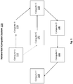
- the example networked computer system 100 includes seven computing devices: Computer A 110, Computer B 120, Computer C 130, Computer D 140, Computer E 150, Computer F 160, and Computer G 170. These computing devices may each be of any type of computing device capable of being connected to a network, e.g. a desktop, a laptop, a router, a mainframe, and/or a smartphone.
- a network e.g. a desktop, a laptop, a router, a mainframe, and/or a smartphone.
- the arrows between the computing devices represent network connections between the computing devices.
- the represented network connections are unidirectional, e.g. a first computer being connected to a second computer does not imply that the second computer is connected to the first computer, and the represented network connections are in the directions shown by the respective arrow.
- the solid arrows represent connections that are consistently present throughout all of the examples described below.
- the dashed arrow represents a network connection which is initially present but is subsequently removed, e.g. a network connection that becomes disconnected.
- the dotted arrow represents a network connection which is not initially present but is subsequently added, e.g. a new network connection between two devices.
- Computer A 110 is initially connected to Computer B 120 but is subsequently disconnected from Computer B 120.
- Computer A 110 is not initially connected to Computer G 170 but is subsequently connected to Computer G.
- Computer B 120 is connected to Computer C 130.
- Computer C 130 is connected to Computer D 140.
- Computer D 140 is connected to Computer E 150.
- Computer E 150 is connected to Computer F 160.
- Computer G 170 is connected to Computer C 130.
- Graph databases represent data using graph structures comprised of nodes and relationships. Nodes are used to represent data items in the database, while relationships represent relationships between these data items. In graph databases, relationships themselves are persisted in the database. This contrasts with many other databases where relationships are inferred at query time using other data. For example, in relational databases, relationships are represented using join keys and join tables which are used at query time to infer relationships.
- traversing relationships in a graph database is comparatively fast compared to traversing relationships in other types of databases, e.g. relational databases.
- graph databases provide more flexibility than other database types. Graph databases are not bound to a pre-defined structure, and attributes and relationships may be easily added and/or removed.
- triplestores store data as triples.
- a triple has three parts. These three parts maybe called: the subject, the predicate and the object.
- the subject of the triple represents the entity performing an action or having a property.
- the predicate represents the action or the nature of the property.
- the object describes the entity which the action is being performed to or the value of the property.
- a triple Computer_A is_connected_to Compute r_B represents the fact that Computer A 110 is connected to Computer B 120.
- a triple may also be understood as a directed relationship from a first node to a second node: the first element representing the first node; the second element representing the type of the relationship between the nodes; and the third element representing the second node.
- the relationships initially stored in a graph database are derived from external data sources and/or manually inputted by a user. These relationships may be referred to as foundational relationships. Based on these foundational relationships, further nodes and relationships can be derived. These relationships are inferred using rules, whereby each rule defines both a precondition, which is either satisfied or not depending on the relationships present in the graph database, and one or more inferred relationships to be added to the graph database if the precondition is satisfied.
- the preconditions and inferred relationships may make use of constants and/or variables to designate the nodes to which a precondition is applicable or for which an inferred relationship is to be created: constants reference a specific node, while variables may be matched during inference to any of a plurality of nodes in the graph database.
- a variable may be referred to several times in a given rule, signifying that all the occurrences of the variable designate a same node of the graph database.
- the precondition of the rule is the part of the rule before the implies symbol, ⁇ , and the inferred relationship is the part of the rule after the implies symbol.
- the elements $c1, $c2, and $c3 are variables that are bound to nodes during inference.
- the precondition checks whether a first node, bound to the variable $c1, has an is_connected_to relationship with a second node, bound to the variable $c2 , and whether this second node, has an is_connected_to relationship with a third node, bound to the variable $c3 . If the precondition is true for the first node, second node and third node then an inferred relationship, $c1 is_connected_to $c3 is added to the graph database. This inferred relationship indicates that this first node has an is_connected_to relationship with the third node.
- the rule may be applied in an example graph database as follows.
- a graph database storing the following relationships:
- the rule may be applied to these relationships to infer several further relationships.
- the precondition is satisfied where: the variable $c1 is bound to Computer_A; the variable $c2 is bound to Computer_B; and the variable $c3 is bound to Computer_C. Therefore, the relationship Computer_A is_connected_to
- Compute r_c is inferred and stored in the graph database.
- the rule may then be applied again to the contents of the graph database, including the newly added relationship, with at least one of the variables bound to a different node.
- the precondition is also satisfied where: the variable $c1 is bound to Computer_A; the variable $c2 is bound to Computer_C; and the variable $c3 is bound to Computer_D.
- the relationship Computer_A is_connected_to Computer_D is inferred and stored in the graph database. This process is repeated until each relationship inferable using the rule has been inferred.
- inference rules may be applied to foundational relationships in a graph database as a batch operation rather than as a series of incremental operations. Therefore, when the foundational relationships are changed, the existing inferred relationships may be deleted from the database, the foundational relationships updated or refreshed, and the inference rules rerun across the foundational relationships, regardless as to whether they are new or unchanged, to determine an updated set of inferred relationships. As rerunning the inference rules across the foundational relationships is computationally expensive, updates may be applied to the graph database infrequently, e.g. once a day or less.
- the subject innovations relate to providing system and methods to reduce the computational resources used to update graph databases. These systems and methods may be particularly applicable when online or near online data analysis using a graph database is desired, e.g. online analysis of networked computer systems, such as the networked computer system 100.
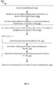
- Figure 2 is a flow diagram of an example method 200 for deleting relationships from a graph database. The method may be performed by executing computer-readable instructions using one or more computing devices.
- update request(s) are received.
- These update request(s) may be messages received using a message queue, input from a user and/or retrieved by polling a data source, e.g. a database or file, to determine any changes.
- a data source e.g. a database or file
- the set of foundational relationship(s) for deleting from the graph database are identified from the update request.
- the set of foundational relationship(s) for deleting may be identified by analysing the received update requests and determining which of these update requests relate to one or more deletions.
- the set of foundational relationships for storing may be stored in one or more appropriate data structures, e.g. an array, a linked list or a set data structure.
- This may be phrased as initially setting the set of relationships for deletion, , to the foundational relationship(s) for deletion.
- deletion working set of relationships contains at least one relationship, e.g. while the deletion working set of relationships is not the empty set, the steps 252, 254 and 256 are iterated. This while condition may be represented in mathematical notation as W D ⁇ 1 , as illustrated in Figure 2 .
- a new deletion working set of relationships, ' is determined.
- the new deletion working set of relationships is determined such that it contains those relationships inferable, by one or more relationship inference rules, using the existing deletion working set of relationships, .
- An example method of how the new deletion working set of relationships, ', may be determined is described in relation to Figure 3 .
- This may be phrased as setting the deletion working set of relationships to the new deletion working set of relationships.
- the set of relationships for deletion includes the foundational relationships for deletion, , and the relationships inferred from them.
- step 260 the set of relationships for deletion, , is deleted from the graph database.
- the described deletion method 200 considerably reduces the computational resources used when deleting data from a graph database compared to existing methods. Unlike existing methods, where the rules are rerun across all foundational relationships in a graph database, the inference rules are specifically run on the foundational relationships for deletion and the relationships derived from these. Therefore, the number of inferences to be performed is substantially reduced. Each of these inferences uses computational resources, hence, the amount of computational resources used is also substantially reduced.
- Figure 3 is a flow diagram of an example method 252 for determining a new deletion working set of relationships, ', and may be utilized as part of the deletion method 200 described in relation to Figure 2 .
- the initial set of foundational relationships includes at least:
- a new deletion working set of relationships, ' is initialised, e.g. an empty data structure for containing relationships is created.
- the set of relationship inference rules includes a single rule, which is the rule described above, i.e.:
- step 320 the deletion working set of relationships, is searched for any relationships which match a relationship specified by the precondition of the rule. These matching relationships may be referred to as the set of deletion matching relationships, RD. If no matching relationships are found then execution immediately proceeds to the next iteration, e.g. searching for any relationships which match a relationship specified by the precondition of the next rule.
- step 330 it is determined whether the precondition is satisfiable when at least the relationship, r, is matched with the relationship specified by the precondition.
- any variables specified by the matching relationship of the precondition are bound to the values of the relationship and, then, it is determined whether the remaining relationships specified by the precondition are satisfiable by relationships in the initial foundational set of relationships stored in the graph database and/or in the deletion working set of relationships. If so, the relationships specified by the precondition are matched to those relationships that satisfy the precondition, and the variables in the precondition correspondingly bound. If the remaining relationships specified by the precondition are not satisfiable then execution immediately proceeds to the next iteration, e.g. determining whether the precondition is satisfiable when a next relationship, r', in the set of matching relationships, R, is matched with the relationship specified by the precondition.
- step 340 new relationship(s), are inferred using the rule based on the relationships to which the precondition is matched and the values to which the variables are bound to as a result.
- the relationship determination steps are performed again for the next rule until the relationship determination steps have been performed for each rule.
- the described method 300 substantially reduces the computational resources used in determining whether the rule is satisfiable. This is because a relationship specified by the rule is first matched with a relationship in the deletion working set and variables correspondingly bound. By pre-binding these variables, the number of relationships to be searched to determine whether the rule is satisfiable is greatly reduced. For example, in the example described above, the relationship $c1 is_connected_to $c2 may be matched with the relationship Computer_A is_connected_to Computer_B with $c1 bound to Computer_A and $c2 bound to Computer_B.
- the relationships to be searched to determine whether the precondition is satisfiable are those where Computer_B is the first element, e.g. the subject, rather than having to search all or at least a significant proportion of the is_connected_to relationships in the graph database.
- Figure 4 is a flow diagram of an example method 400 for storing relationships to a graph database. The method may be performed by executing computer-readable instructions using one or more computing devices.
- the step 210 is performed, i.e. update request(s) are received.
- the set of foundational relationship(s) for storing to the graph database, s are identified from the update request.
- the set of foundational relationship(s) for storing may be identified by analysing the received update requests and determining which of these update requests relate to storing one or more foundational relationships.
- the set of foundational relationships for storing may be stored in one or more appropriate data structures, e.g. an array, a linked list or a set data structure.
- This may be phrased as initially setting the set of relationships for storing to the foundational relationship(s) for storing.
- This may be phrased as creating , e.g. initializing, a storing working set of relationships and setting it to the foundational relationship(s) for storing.
- While the storing working set of relationships contains at least one relationship, e.g. while the storing working set of relationships is not the empty set, the steps 452, 454 and 456 are iterated. This while condition may be represented in mathematical notation as W S ⁇ 1, as illustrated in Figure 4 .
- a new storing working set of relationships, ' is determined.
- the new storing working set of relationships is determined such that it contains those relationships inferable, by one or more relationship inference rules, using the existing storing working set of relationships, .
- An example method of how the new storing working set of relationships, ', may be determined is described in relation to Figure 3 .
- This may be phrased as setting the new storing working set of relationships to the storing working set of relationships.
- the set of relationships for storing, includes the foundational relationships for storing, , and the relationships inferred from them.
- step 460 the set of relationships for storing, , is stored to the graph database.
- the described storing method 400 considerably reduces the computational resources used when storing data to a graph database compared to existing methods. Unlike existing methods, where the rules are rerun across all foundational relationships in a graph database, the inference rules are specifically run on the foundational relationships for storing and the relationships derived from these. Therefore, the number of inferences to be performed is substantially reduced. Each of these inferences uses computational resources, hence, the amount of computational resources used is also substantially reduced.
- Figure 5 is a flow diagram of an example method 452 for determining a new storing working set of relationships, ', and may be utilized as part of the storing method 400 described in relation to Figure 4 .
- the initial set of foundational relationships includes at least:
- a new storing working set of relationships, ' is initialised, e.g. an empty data structure for containing relationships is created.
- the set of relationships rule includes a single rule, which is the rule described above, i.e.:
- step 520 the storing working set of relationships, ', is searched for any relationships which match a relationship specified by the precondition of the rule. These matching relationships may be referred to as the set of storing matching relationships, . If no matching relationships are found then execution immediately proceeds to the next iteration, e.g. searching for any relationships which match a relationship specified the precondition of the next rule.
- step 530 it is determined whether the precondition is satisfiable when at least the relationship, r, is matched with the relationship specified by the precondition.
- any variables specified by the matching relationship of the precondition are bound to the values of the relationship and, then, it is determined whether the remaining relationships specified by the precondition are satisfiable by relationships in the initial foundational set of relationships and/or in the storing working set of relationships. If so, the relationships specified by the precondition are matched to those relationships that satisfy the precondition, and the variables in the precondition correspondingly bound. If the remaining relationships specified by the precondition are not satisfiable then execution immediately proceeds to the next iteration, e.g. determining whether the precondition is satisfiable when a next relationship, r', in the set of matching relationships, R, is matched with the relationship specified by the precondition.
- step 540 new relationship(s), are inferred using the rule based on the relationships to which the precondition is matched and the values to which the variables are bound to as a result.
- the relationship determination steps are performed again for the next rule until the relationship determination steps have been performed for each rule.
- the described method 500 substantially reduces the computational resources used in determining whether the rule is satisfiable for the same reasons as the described method 300.
- Figure 6 is a flow diagram of an example method 600 for updating a graph database. The method may be performed by executing computer-readable instructions using one or more computing devices.
- step 210 update request(s) are received, as described in relation to the method 200 and method 400.
- step 220 the set of foundational relationship(s) for deleting from the graph database, , are identified from the update request, as described in relation to the method 200.
- step 420 the set of foundational relationship(s) for storing to the graph database, s, are identified from the update request, as described in relation to the method 400.
- a pre-update set of relationships is set to the set of foundational relationships stored in the graph database, , e.g. the set of foundational relationships in the graph database before the update has been applied.
- a post-update set of relationships, ' is set to the set of foundational relationships stored in the graph database with the updates to the foundational relationships applied.
- the steps 630, 254, 454, 256, and 456 are iterated. This while condition may be represented in mathematical notation as ' W D ⁇ 1 and/or W S ⁇ 1 ′ , as illustrated in Figure 6 .
- the new deletion working set of relationships, ', and the new storing working set of relationships, ' are determined.
- the new deletion working set of relationships is determined such that it contains those relationships inferable, by one or more relationship inference rules, from the storing working set, , prior, but not subsequent, to the updating of the foundational relationships in the graph database.
- the new storing working set of relationships is determined such that it contains those relationships inferable, by one or more relationship inference rules, from the storing working set, , subsequent, but not prior, to the updating of the foundational relationships in the graph database
- An example method of how the new deletion working set of relationships, ', and the new storing working set of relationships, ', are determined is described in relation to Figure 7 .
- the set of relationships for deletion includes the foundational relationships for deletion, , and the relationships inferred from them except for any relationships which would still be inferred due to the addition of the foundational relationships for storing.
- the set of relationships for storing includes the foundational relationships for storing, , and the relationships inferred from them, except for any relationships which would not be inferred due to the removal of the foundational relationships for deletion.
- step 260 the set of relationships for deletion, , is deleted from the graph database, as described in relation to the method 200.
- step 460 the set of relationships for storing, , is stored to the graph database, as described in relation to the method 400.
- Figure 7 is a flow diagram of an example method 630 for determining a new deletion working set of relationships, ', and a new storing working set of relationships, ', and may be utilized as part of the update method 600 described in relation to Figure 6 .
- a new deletion working set of relationships, ' is initialised, e.g. an empty data structure for containing relationships is created.
- a new storing working set of relationships, ' is initialised, e.g. an empty data structure for containing relationships is created.
- step 320 the deletion working set of relationships, is searched for any relationships which match a relationship specified by the precondition of the rule. These matching relationships may be referred to as the set of deletion matching relationships, .
- step 520 the storing working set of relationships, is searched for any relationships which match a relationship specified by the precondition of the rule. These matching relationships may be referred to as the set of storing matching relationships, .
- step 720 it is determined whether the precondition is satisfiable when at least the relationship, r, is matched with the relationship specified by the precondition. To make this determination, any variables specified by the matching relationship of the precondition are bound to the values of the relationship and, then, it is determined whether the remaining relationships specified by the precondition are satisfiable by relationships in the pre-update set of relationships, . If so, the relationships specified by the precondition are matched to those relationships that satisfy the precondition, and the variables in the precondition correspondingly bound.
- step 730 a set of pre-update inferred relationships, is inferred using the rule based on the relationships to which the precondition is matched and the values to which the variables are bound to as a result.
- step 722 it is determined whether the precondition is satisfiable when at least the relationship, r, is matched with the relationship specified by the precondition. To make this determination, any variables specified by the matching relationship of the precondition are bound to the values of the relationship and, then, it is determined whether the remaining relationships specified by the precondition are satisfiable by relationships in the post-update set of relationships, '. If so, the relationships specified by the precondition are matched to those relationships that satisfy the precondition, and the variables in the precondition correspondingly bound.
- step 732 a set of post-update inferred relationships, is inferred using the rule based on the relationships to which the precondition is matched and the values to which the variables are bound to as a result.
- fewer inference operations may be performed as by using the differences between the set of pre-update inferred relationships and the set of post-update inferred relationships, as described, at least some unnecessary inferences are forestalled. Some unnecessary inferences are forestalled at least because where new relationship(s) are to be stored that, for the purposes of the inference rule(s), replace other relationship(s) for deletion, the (same) relationships inferred from each of these may not be added to the storing working sets and deletion working sets before further (corresponding) relationships are needlessly inferred for both deletion and storing.
- the inferred and foundational relationships stored in the graph database represent a network, e.g. a telephone or computer network, as such networks typically include transitive relationships.
- a connection between Computer A 110 and Computer B 120 may be removed, through which Computer A 110 is indirectly connected to a number of other computers: Computer C 130, Computer D 140, Computer E 150, and Computer 160.
- a connection from Computer A 110 to Computer G 170, which is itself connected to Computer C 130 may be established substantially contemporaneously.
- the described method would facilitate the updating of a graph database representing the networked computer system 100, such that the relationship representing the connection between Computer A 110 and Computer B 120 is removed, and a relationship representing connection between Computer G 170 and Computer C 130 is added, without performing unnecessary inference operations relating to the computers which Computer A 110 remains indirectly connected to.
- This is at least because a relationship Computer_A is_connected_to Computer_C would be inferred using both the pre-update set of relationships and the post-update set of relationships, hence this relationship would not be added to the new deletion working set of relationships or the new storing working set of relationship. Therefore, the relationship Computer_A is_connected_to Computer_C would not be present in the working sets for the next iteration and no further relationships would (needlessly) be inferred from it.
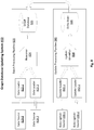
- a computer system 800 for updating a graph database is shown.
- the described computer system may be implemented on any suitable computing device, across several networked computing devices, and/or on a cloud computing system.
- the computer system 800 may be implemented by one or more computing devices of the type described with respect to Figure 9 .
- the graph database system includes data sources 810-1, 810-2, a batch processing pipeline 820, data update sources 830-1, 830-2, and an update processing pipeline 840.
- the data sources 810-1, 810-2 are used as inputs to the batch processing pipeline 820. These data sources may comprise data that is updated infrequently, e.g. historical network activity data, or a database of network hardware properties. These data sources may be in a stored in a manner suitable for batch processing, e.g. as a flat file or in binary large object storage.
- the batch processing pipeline 820 is configured to perform an initial load or a reload of a graph database 826 from data sources 810-1 suited for batch processing.
- the batch processing pipeline 820 is configured to be run infrequently, e.g. daily or weekly.
- the batch processing pipeline includes data loaders 822-1, 822-2, a reasoner 824, and a graph database 826.
- the data loaders 822-1, 822-2 are software configured to load data from the respective data sources 810-1, 810-2 and convert and output the loaded data into a form suitable for processing by the reasoned 824.
- the data loaders 822-1, 822-2 may convert the loaded data into triples or another representation of a relationship between two nodes, e.g. a tuple.
- the output of the data loaders 822-1 is then processed by the reasoner 824 which applies relationship inference rules to infer further relationships from the relationships in the loaded data. Both the relationships output by the data loader and these determined further relationships are then stored to the graph database 826.
- the graph database 826 may be any database suitable for storing relationships.
- the graph database 826 may be a triplestore, e.g. a resource description framework store, another type of native graph database, e.g. a labelled property graph database, or any database configured to store relationships.
- the data update sources 830-1, 830-2 are used as inputs to the update processing pipeline 840.
- These update data sources 830-1, 830-2 may comprise data that is updated frequently, e.g. data representing recent changes to the state of a network, e.g. changes occurring within the last minute, last ten minutes or the last hour.
- These data update sources 830-1, 830-2 may be data storage systems and/or software adapted for supplying data frequently, e.g. a message queue, an event queue, or a web service request receiver.
- the data update loaders 842-1, 842-2 are software configured to load data updates from the respective data update sources 830-1, 830-2 and convert and output the loaded data updates into a form suitable for processing by the update identifier.
- the data update loaders 842-1, 842-2 may convert the loaded data update into triples or another representation of a relationship between two nodes, e.g. a tuple.
- the output of the data loaders 822-1 is then processed by the update identifier 844 which applies relationship inference rules in accordance with the above described methods to determine inferred relationships for storing to and/or deleting from the graph database 826.
- relationship inference rules in accordance with the above described methods to determine inferred relationships for storing to and/or deleting from the graph database 826.
- the deltas are then stored to the delta store 846.
- the delta store 846 is storage for temporarily storing the deltas prior to their application to the graph database.
- the delta store 846 may be any storage suited for temporary storage of data, e.g. an in-memory database or cache; or application memory, such as the memory of the update identifier 824.
- the deltas in the delta store 846 are applied to the graph database 826.
- the deltas may be applied when the graph database is experiencing below average load, such as to minimise the impact of the update on users of the graph database 826.
- the deltas may be applied at a frequency less than that at which the data updates are received but greater than that at which reloads of the graph database occur. For example, deltas may be applied at a frequency of every five minutes to hourly.
- Figure 9 is a schematic block diagram illustrating a computing device 900 usable for one or more components for systems, e.g. graph database updating system 700, or software methods, e.g. methods 200, 252, 400, 452, 600, and 630, implementing the subject innovations.
- the illustrated computing device 900 is intended as an example only, and any other suitable computing device capable of implementing the subject innovations may be used. These computing devices may have different functionality, components and/or different interconnections between components.
- the computing device may take any suitable form, e.g. a rack server, a desktop computer, a mainframe, a laptop computer, or a smartphone.
- Computing device 900 includes a processor 902, a main memory 904, a storage device 906 and a network interface 908. These components of the computing device 900 are coupled to a bus 910 of the computing device.
- the processor 902 is a hardware processor configured to execute one or more computer executable instructions stored on the main memory 904.
- the processor 902 may be a general purpose processor, e.g. a central processing unit.
- the processor 902 may have multiple cores and/or be capable of executing multiple cores on a single thread, e.g. by using simultaneous multi-threading.
- the processor 902 may contain one or more registers and/or one or more local caches.
- the processor 902 may be or include a specialised processor, e.g. a graphics processing unit, or a field programmable gate array (FPGA) or application-specific integrated circuit (ASIC) configured to perform specified operations such as one or more steps of the above described methods. While a processor 902 is referred to, the computing device 900 may include a plurality of processors 902, and these processors may be of the same or different types.
- the main memory 904 may be one or more random access memories, or another suitable type of memory for storing instructions or information to be utilized by the processor 902, e.g. a flash memory.
- the main memory 904 is a non-transitory, computer-readable medium.
- the main memory 904 may be a volatile memory. Alternatively, it may be a persistent memory of sufficient speed to support the storing of instructions or information undergoing use by the processor.
- the main memory 904 may also include a volatile component and a persistent component.
- the main memory 904 stores computer-readable instructions for executing and/or implementing these systems and/or methods, or components thereof, or one or more computer-readable instructions implementing software utilized in these systems and/or methods, e.g. a graph database server.
- the storage device 906 is a persistent, mass storage device.
- the storage device 906 may be a hard disk drive, a solid state drive, a flash memory or any other suitable persistent storage device.
- the storage device 906 may store a persisted computer program including instructions that are or may be transformed into instructions usable to execute the described methods and/or implement the described systems.
- the storage device 906 may include a compiled binary executable that may be loaded into main memory 904 for execution by the processor 902.
- the network interface 908 is a device configured to facilitate communication between the computing device 900 and networks.
- the network interface 908 may be a wired network interface, e.g. an Ethernet or fibre optic network interface, or a wireless network interface, e.g. a Wi-Fi interface; microwave network link interface, or mobile network interface, e.g. a 4G or 5G network interface.
- the network interface 908 may be integrated into another component of the computing device 900, e.g. into a motherboard of the computing device 900 , or may be part of a network interface card, e.g. a PCI Express card, or network interface peripheral, e.g. a USB network peripheral.
- the bus 910 is any suitable device for coupling the components of the computer system 900.
- the bus 910 may be or may be part of a motherboard or other interconnection fabric, e.g. a silicon interconnect fabric, of the computing device 900.
- a display 912 may be connected to the computing device 900 via the bus 910.
- the display may be a liquid crystal display (LCD), an organic light emitting diode (OLED) display, a cathode ray tube (CRT) display, or any other suitable type of display.
- the display may be used to display one or more outputs based on computer-readable instructions executed using computing device 900.
- the display 912 may also be used to display status information of the computing device and/or computer software being executed thereon.
- An input device 914 may be connected to the computing device 900 via the bus 910.
- the input device 914 may be any input device suitable for receiving input from a user for inputting to the computing device 900.
- the input device may be a keyboard, a pointer device, such as a mouse or touch screen, or a microphone.
- a local network 922 is connected to the computing device 900 via the network interface 908.
- the local network may be any suitable type of network which can be connected to the computing device via then network interface.
- the local network 922 may be a wired network, a wireless network and/or contain both wired and wireless aspects.
- the computing device 900 may be connected to the Internet 924 and one or more local servers 926.
- One or more cloud computing devices may be used to implement the subject innovations in conjunction with the computing device 00, and the computing device 900 may be connected to these cloud computing devices via the Internet 924. Additionally or alternatively, the one or more local servers 926 may be used in conjunction with the computing device 900 to implement the subject innovations.
- references contained herein in to 'setting' a first set of relationships to another second set of relationships, in any tense or voice, e.g. 'is set to', 'set to', etc., relate to any operation(s) whereby, on completion of the operation(s), the first set of relationships and the second set of relationships contain the same elements.
- Such 'setting' operation(s) may be completed by assigning a reference, such that the second set of relationships references the same underlying data structure and/or relationships referenced by the first set of relationships.
- Such 'setting' operation(s) may alternatively or additionally be completed by copying the relationships contained in the first set of relationships and adding these copies of the relationships of the first set to a data structure representing the second set of relationships.
- references contained herein in to 'adding' a second set of relationships to another first set of relationships relate to any operation(s) whereby, on completion of the operation(s), the first set of relationships contains the relationships present in the second set.
- Such 'adding' operation(s) may be completed by adding the relationships to an extendible data structure or a data structure having sufficient empty space, e.g. adding the relationships to a linked list or an array having sufficient empty.
- such 'adding' operation(s) may alternatively or additionally be completed by copying the relationships previously contained in the data structures for the first set of relationships and the second set of relationships to a new data structure representing their addition, and assigning a variable for the second set of relationships to this new data structure.
Description
- This specification relates to systems and methods for updating graph databases.
- Graph databases represent data using graph structures comprised of nodes and relationships. Nodes are used to represent data items in the database, while relationships represent relationships between these data items. In graph databases, relationships themselves are persisted in the database unlike other types of database. A type of graph database is a triplestore. Triplestores store data as triples. A triple has three parts, which may be called: the subject, the predicate and the object. An example of prior art is the document
WO2017/189026 describes a known method for querying and updating a graph database. - A first aspect of the specification provides a computer-implemented method including: receiving one or more update requests; identifying, based on the one or more update requests, a set of foundational relationships for deletion from a graph database; inferring, using one or more relationship inference rules, a set of inferred relationships for deletion from the graph database based on the set of foundational relationships for deletion, and deleting, from the graph database, a set of relationships for deletion comprising the set of foundational relationships for deletion and the set of inferred relationships for deletion.
- Inferring the set of inferred relationships for deletion may include: searching for relationships in the set of foundational relationships for deletion that match a relationship specified in a precondition of at least one of the one or more relationship inference rules; determining whether the precondition is satisfiable using at least one of the matching relationships; and in response to the precondition being satisfiable, inferring at least one of the relationships of the set of inferred relationships for deletion using at least one of the matching relationships.
- Determining whether the precondition is satisfiable using at least one of the matching relationships may include pre-binding one or more variables in the precondition to one or more nodes connected by the at least one of the matching relationships. Determining whether the precondition is satisfiable may further include determining whether one or more remaining relationships specified in the precondition are satisfiable using one or more relationships stored in the graph database.
- The provided method may include identifying, based on the one or more update requests, a set of foundational relationships for storing to the graph database; and inferring, using one or more relationship inference rules, a set of inferred relationships for storing to the graph database based on the set of foundational relationships for storing; and storing, to the graph database, a set of relationships for storing comprising the set of foundational relationships for storing and the set of inferred relationships for storing.
- Inferring the set of inferred relationships for storing may include: searching for relationships in the set of foundational relationships for storing that match a relationship specified in a precondition of at least one of the one or more relationship inference rules; determining whether the precondition is satisfiable using at least the matching relationship; and in response to the precondition being satisfiable, inferring at least one of the relationships of the set of inferred relationships for storing using at least the matching relationship.
- Inferring the set of inferred relationships for storing may include: setting a storing working set of relationships to the set of foundational relationships for storing to the graph database; while the storing working set of relationships contains at least one relationship: initialising a new storing working set of relationships; for each relationship inference rule of the one or more relationship inference rules: searching for relationships in the storing working set of relationships that match a relationship specified in a precondition of the relationship inference rule; for each matching relationship: determining whether the precondition is satisfiable using at least the matching relationship; in response to the precondition being satisifiable: infer one or more relationships using the relationship inference rule; and updating the new storing working set of relationships based on the inferred one or more relationships; and setting the storing working set of relationships based on the new storing working set of relationships.
- Inferring the set of inferred relationships for deletion may include: setting a deletion working set of relationships to the set of foundational relationships for deleting from the graph database; while the deletion working set of relationships contains at least one relationship: initialising a new deletion working set of relationships; for each relationship inference rule of the one or more relationship inference rules: searching for relationships in the deletion working set of relationships that match a relationship specified in a precondition of the relationship inference rule; for each matching relationship: determining whether the precondition is satisfiable using at least the matching relationship;
in response to the precondition being satisifiable: infer one or more relationships using the relationship inference rule; and updating the new deletion working set of relationships based on the inferred one or more relationships; and setting the deletion working set of relationships based on the new deletion working set of relationships. - Inferring one or more relationships using the relationship inference rule comprises: inferring a set of pre-update inferred relationships based on foundational relationships stored in the graph database and/or relationships inferred therefrom; and inferring a set of post-update inferred relationships based on the difference between foundational relationships stored in the graph database and the set of foundational relationships for deleting, the set of foundational relationships for storing and/or relationships inferred therefrom.
- Updating the new storing working set of relationships may include adding, to the new storing working set of relationships, a difference between the set of post-update inferred relationships and the set of pre-update inferred relationships.
- Updating the new deletion working set of relationships may include adding, to the new deletion working set of relationships, a difference between the set of pre-update inferred relationships and the set of post-update inferred relationships.
- The graph database may be a triplestore.
- At least one of the one or more update requests may be received in response to a change in the state of a network. The change in the state of the network may include a network disconnection between two devices. The set of foundation relationships for deletion may include a relationship representing the network connection between the two devices. The set of inferred relationships for deletion may include one or more relationships representing one or more network connections between devices transitively connected by the network connection between the two devices.
- A second aspect provides a computer program comprising instructions which, when the program is executed by a computer, cause the computer to carry out any method described above.
- A third aspect provides a data processing system comprising one or more processors configured to perform any method described above.
- Certain embodiments of the present specification will now be described by way of example with reference to the following figures.
-
Figure 1 is a schematic block diagram illustrating a networked computer system analysable using the systems and methods described herein; -
Figure 2 is a flow diagram of an example method for deleting relationships from a graph database; -
Figure 3 is a flow diagram of an example method for determining a new deletion working set of relationships; -
Figure 4 is a flow diagram of an example method for storing relationships to a graph database; -
Figure 5 is a flow diagram of an example method for determining a new storing working set; -
Figure 6 is a flow diagram of an example method for updating a graph database; -
Figure 7 is a flow diagram of an example method for determining a new storing working set and determining a new deletion working set; -
Figure 8 is a schematic block diagram illustrating a computer system configured to update a graph database; and -
Figure 9 is a schematic block diagram illustrating a computing device usable for one or more components for systems or software methods implementing the subject innovations. - For the purposes of explanation, examples of how the subject innovations may be applied are included herein. These examples relate to using relationships in a graph database to represent connections between computers in a networked computing system.
Figure 1 illustrates such a networkedcomputer system 100. - The example networked
computer system 100 includes seven computing devices: Computer A 110,Computer B 120, Computer C 130,Computer D 140, Computer E 150, Computer F 160, and Computer G 170. These computing devices may each be of any type of computing device capable of being connected to a network, e.g. a desktop, a laptop, a router, a mainframe, and/or a smartphone. - The arrows between the computing devices represent network connections between the computing devices. For ease of explanation, the represented network connections are unidirectional, e.g. a first computer being connected to a second computer does not imply that the second computer is connected to the first computer, and the represented network connections are in the directions shown by the respective arrow.
- The solid arrows represent connections that are consistently present throughout all of the examples described below. The dashed arrow represents a network connection which is initially present but is subsequently removed, e.g. a network connection that becomes disconnected. The dotted arrow represents a network connection which is not initially present but is subsequently added, e.g. a new network connection between two devices.
-
Computer A 110 is initially connected toComputer B 120 but is subsequently disconnected fromComputer B 120. Computer A 110 is not initially connected to Computer G 170 but is subsequently connected to Computer G. Computer B 120 is connected toComputer C 130.Computer C 130 is connected toComputer D 140.Computer D 140 is connected toComputer E 150.Computer E 150 is connected to Computer F 160.Computer G 170 is connected toComputer C 130. - Graph databases represent data using graph structures comprised of nodes and relationships. Nodes are used to represent data items in the database, while relationships represent relationships between these data items. In graph databases, relationships themselves are persisted in the database. This contrasts with many other databases where relationships are inferred at query time using other data. For example, in relational databases, relationships are represented using join keys and join tables which are used at query time to infer relationships.
- As the relationships are persisted in the database rather than having to be inferred at query time, traversing relationships in a graph database is comparatively fast compared to traversing relationships in other types of databases, e.g. relational databases. Furthermore, graph databases provide more flexibility than other database types. Graph databases are not bound to a pre-defined structure, and attributes and relationships may be easily added and/or removed.
- One type of graph database is known as a triplestore. Triplestores store data as triples. As the name suggests, a triple has three parts. These three parts maybe called: the subject, the predicate and the object. The subject of the triple represents the entity performing an action or having a property. The predicate represents the action or the nature of the property. The object describes the entity which the action is being performed to or the value of the property. For example, a triple Computer_A is_connected_to Compute r_B represents the fact that
Computer A 110 is connected toComputer B 120. While the subject, predicate, object terminology is useful for understanding triples, it should be noted that a triple may also be understood as a directed relationship from a first node to a second node: the first element representing the first node; the second element representing the type of the relationship between the nodes; and the third element representing the second node. - The relationships initially stored in a graph database are derived from external data sources and/or manually inputted by a user. These relationships may be referred to as foundational relationships. Based on these foundational relationships, further nodes and relationships can be derived. These relationships are inferred using rules, whereby each rule defines both a precondition, which is either satisfied or not depending on the relationships present in the graph database, and one or more inferred relationships to be added to the graph database if the precondition is satisfied. The preconditions and inferred relationships may make use of constants and/or variables to designate the nodes to which a precondition is applicable or for which an inferred relationship is to be created: constants reference a specific node, while variables may be matched during inference to any of a plurality of nodes in the graph database. A variable may be referred to several times in a given rule, signifying that all the occurrences of the variable designate a same node of the graph database.
- For the purposes of explanation, an example of a rule is given below:
($c1 is_connected_to $c2 and $c2 is_connected_to $c3) ⇒ ($c1 is_connected_to $c3). - The precondition of the rule is the part of the rule before the implies symbol, ⇒, and the inferred relationship is the part of the rule after the implies symbol. The elements $c1, $c2, and $c3 are variables that are bound to nodes during inference. In the example, the precondition checks whether a first node, bound to the variable $c1, has an is_connected_to relationship with a second node, bound to the variable $c2, and whether this second node, has an is_connected_to relationship with a third node, bound to the variable $c3. If the precondition is true for the first node, second node and third node then an inferred relationship, $c1 is_connected_to $c3 is added to the graph database. This inferred relationship indicates that this first node has an is_connected_to relationship with the third node.
- The rule may be applied in an example graph database as follows. Consider a graph database storing the following relationships:
- Computer_A is_connected_to Computer_B
- Computer_B is_connected_to Computer_C
- Computer_C is_connected_to Computer_D
- Computer_D is_connected_to Computer_E
- Computer_E is_connected_to Computer_F.
- The rule may be applied to these relationships to infer several further relationships. For example, the precondition is satisfied where: the variable $c1 is bound to Computer_A; the variable $c2 is bound to Computer_B; and the variable $c3 is bound to Computer_C. Therefore, the relationship Computer_A is_connected_to
- Compute r_c is inferred and stored in the graph database. The rule may then be applied again to the contents of the graph database, including the newly added relationship, with at least one of the variables bound to a different node. For example, subsequent to the storing of the inferred relationship Computer_A is_connected_to Computer_C, the precondition is also satisfied where: the variable $c1 is bound to Computer_A; the variable $c2 is bound to Computer_C; and the variable $c3 is bound to Computer_D. As a result, the relationship Computer_A is_connected_to Computer_D is inferred and stored in the graph database. This process is repeated until each relationship inferable using the rule has been inferred.
- For example in this case, the following other relationships would be inferred:
- Computer_A is_connected_to Computer_E
- Computer_A is_connected_to Computer_F
- Computer_B is_connected_to Computer_D
- Computer_B is_connected_to Computer_E
- Computer_B is_connected_to Computer_F
- Computer_C is_connected_to Computer_E
- Computer_C is_connected_to Computer_F
- Computer_D is_connected_to Computer_F.
- As is illustrated by the example above, the outputs of latter inferences are often dependent on previous inferences. Due to these complex interdependencies, inference rules may be applied to foundational relationships in a graph database as a batch operation rather than as a series of incremental operations. Therefore, when the foundational relationships are changed, the existing inferred relationships may be deleted from the database, the foundational relationships updated or refreshed, and the inference rules rerun across the foundational relationships, regardless as to whether they are new or unchanged, to determine an updated set of inferred relationships. As rerunning the inference rules across the foundational relationships is computationally expensive, updates may be applied to the graph database infrequently, e.g. once a day or less.
- Applying updates to the graph database infrequently may be acceptable for offline analysis of data, e.g. post hoc analysis of a network system. However, if online or near online analysis of data is desired, e.g. analysis of the current or recent state of a network system, frequent updating of the graph database is unavoidable. For such frequent updates, rerunning the inference rules across the foundational relationships would use an excessive amount of computational resources. The use of such an excessive amount of computational resources would greatly increase the hardware requirements for such a system and/or increase the time to perform the update such that the system was still not suited to online analysis. Therefore, a method for reducing the computational resources used to update graph databases is desirable.
- The subject innovations relate to providing system and methods to reduce the computational resources used to update graph databases. These systems and methods may be particularly applicable when online or near online data analysis using a graph database is desired, e.g. online analysis of networked computer systems, such as the
networked computer system 100. -
Figure 2 is a flow diagram of anexample method 200 for deleting relationships from a graph database. The method may be performed by executing computer-readable instructions using one or more computing devices. - In
step 210, update request(s) are received. These update request(s) may be messages received using a message queue, input from a user and/or retrieved by polling a data source, e.g. a database or file, to determine any changes. These update requests contain information from which foundational relationships to delete from the graph database can be identified. - In
step 220, the set of foundational relationship(s) for deleting from the graph database,, are identified from the update request. The set of foundational relationship(s) for deleting may be identified by analysing the received update requests and determining which of these update requests relate to one or more deletions. The set of foundational relationships for storing may be stored in one or more appropriate data structures, e.g. an array, a linked list or a set data structure.
- In
step 230, the set of relationships for deletion,, is initially set to the foundational relationship(s) for deletion, i.e.
 , to the foundational relationship(s) for deletion.
 - In
step 240, a deletion working set of relationships,, is created and initially set to the foundational relationship(s) for deletion, i.e.

- While the deletion working set of relationships contains at least one relationship, e.g. while the deletion working set of relationships is not the empty set, the
steps 
Figure 2 . - In
step 252, a new deletion working set of relationships,', is determined. The new deletion working set of relationships is determined such that it contains those relationships inferable, by one or more relationship inference rules, using the existing deletion working set of relationships,. An example method of how the new deletion working set of relationships,', may be determined is described in relation toFigure 3 . - In step 254, the deletion working set of relationships is then set to the new deletion working set of relationships, i.e.

- In
step 256, the deletion working set of relationships is added to the set of relationships for deletion, i.e.
- After the
steps , includes the foundational relationships for deletion,, and the relationships inferred from them. - In
step 260, the set of relationships for deletion,, is deleted from the graph database. - The described
deletion method 200 considerably reduces the computational resources used when deleting data from a graph database compared to existing methods. Unlike existing methods, where the rules are rerun across all foundational relationships in a graph database, the inference rules are specifically run on the foundational relationships for deletion and the relationships derived from these. Therefore, the number of inferences to be performed is substantially reduced. Each of these inferences uses computational resources, hence, the amount of computational resources used is also substantially reduced. -
Figure 3 is a flow diagram of anexample method 252 for determining a new deletion working set of relationships,', and may be utilized as part of thedeletion method 200 described in relation toFigure 2 . - For the purposes of illustration, examples of how the steps of this method 300 may be applied to data representing the
networked computer system 100 are included. In this example, the initial set of foundational relationships includes at least: - Computer_A is_connected_to Computer_B
- Computer_B is_connected_to Computer_C.
- The foundational relationship for deletion in this example is:
Computer_A is_connected_to Computer_B. - In
step 310, a new deletion working set of relationships,', is initialised, e.g. an empty data structure for containing relationships is created. - The following steps are performed for each rule in a set of relationship inference rules.
- In the example, the set of relationship inference rules includes a single rule, which is the rule described above, i.e.:
- ($c1 is_connected_to $c2 and $c2 is_connected_to $c3) ⇒
- ($c1 is_connected_to $c3).
- In
step 320, the deletion working set of relationships,, is searched for any relationships which match a relationship specified by the precondition of the rule. These matching relationships may be referred to as the set of deletion matching relationships, RD. If no matching relationships are found then execution immediately proceeds to the next iteration, e.g. searching for any relationships which match a relationship specified by the precondition of the next rule. - In the example, the relationship Computer_A is_connected_to Computer_B is matched with the relationship specified by the precondition:
$c1 is_connected_to $c2. - The following steps are then performed for each relationship, r, in the set of matching relationships, RD.
- In step 330, it is determined whether the precondition is satisfiable when at least the relationship, r, is matched with the relationship specified by the precondition. To make this determination, any variables specified by the matching relationship of the precondition are bound to the values of the relationship and, then, it is determined whether the remaining relationships specified by the precondition are satisfiable by relationships in the initial foundational set of relationships stored in the graph database and/or in the deletion working set of relationships. If so, the relationships specified by the precondition are matched to those relationships that satisfy the precondition, and the variables in the precondition correspondingly bound. If the remaining relationships specified by the precondition are not satisfiable then execution immediately proceeds to the next iteration, e.g. determining whether the precondition is satisfiable when a next relationship, r', in the set of matching relationships, R, is matched with the relationship specified by the precondition.
- In the example, the variables $c1 and $c2 have been bound to Computer_A and Computer_B, respectively. With these bindings, the precondition of the rule is:
- (Computer_A is_connected_to Computer_B and
- Computer_B is_connected_to $c3).
- Therefore, for this precondition to be satisfied, a relationship specifying that Computer_B is connected to another computer, $c3, should be found. In this case, one such relationship is present, Computer_B is_connected_to Computer_C. As a result, $c3, is bound to Computer_C.
- In step 340, new relationship(s),, are inferred using the rule based on the relationships to which the precondition is matched and the values to which the variables are bound to as a result.

- In the example, the variables $c1, $c2, and $c3 are bound to Computer_A, Computer_B, and Computer_C, respectively. Therefore, the rule is applied as follows:
- (Computer_A is_connected_to Computer_B
- and Computer_B is_connected_to Computer_C) ⇒
- Computer_A is_connected_to Computer_C).
- In the example, the relationship Computer_A is_connected_to Computer_C is inferred.
- In step 350, the inferred relationship(s),, are added to the new deletion working set,', i.e.:

- As previously indicated, once the inference function steps have been repeated for each of the one or more relationships in the deletion working set that can be matched, the relationship determination steps are performed again for the next rule until the relationship determination steps have been performed for each rule.
- The described method 300 substantially reduces the computational resources used in determining whether the rule is satisfiable. This is because a relationship specified by the rule is first matched with a relationship in the deletion working set and variables correspondingly bound. By pre-binding these variables, the number of relationships to be searched to determine whether the rule is satisfiable is greatly reduced. For example, in the example described above, the relationship $c1 is_connected_to $c2 may be matched with the relationship Computer_A is_connected_to Computer_B with $c1 bound to Computer_A and $c2 bound to Computer_B.
- With these variables bound, the precondition of the rule is:
- (Computer_A is_connected_to Computer_B and
- Computer_B is_connected_to $c3).
- As $c2 is already bound, the relationships to be searched to determine whether the precondition is satisfiable are those where Computer_B is the first element, e.g. the subject, rather than having to search all or at least a significant proportion of the is_connected_to relationships in the graph database.
-
Figure 4 is a flow diagram of anexample method 400 for storing relationships to a graph database. The method may be performed by executing computer-readable instructions using one or more computing devices. - As for the
storing method 200, thestep 210 is performed, i.e. update request(s) are received. - In
step 420, the set of foundational relationship(s) for storing to the graph database,s, are identified from the update request. The set of foundational relationship(s) for storing may be identified by analysing the received update requests and determining which of these update requests relate to storing one or more foundational relationships. The set of foundational relationships for storing may be stored in one or more appropriate data structures, e.g. an array, a linked list or a set data structure.
- In
step 430, the set of relationships for storing,, is initially set to the foundational relationship(s) for storing, i.e.

- In
step 440, a storing working set of relationships,, is created and initially set to the foundational relationship(s) for storing, i.e.

- While the storing working set of relationships contains at least one relationship, e.g. while the storing working set of relationships is not the empty set, the
steps 
Figure 4 . - In
step 452, a new storing working set of relationships,', is determined. The new storing working set of relationships is determined such that it contains those relationships inferable, by one or more relationship inference rules, using the existing storing working set of relationships,. An example method of how the new storing working set of relationships,', may be determined is described in relation toFigure 3 . - In
step 454, the storing working set of relationships is then set to the new storing working set of relationships, i.e.
- In
step 456, the storing working set of relationships is added to the set of relationships for storing, i.e.
- After the
steps , includes the foundational relationships for storing,, and the relationships inferred from them.
- In
step 460, the set of relationships for storing,, is stored to the graph database. - The described
storing method 400 considerably reduces the computational resources used when storing data to a graph database compared to existing methods. Unlike existing methods, where the rules are rerun across all foundational relationships in a graph database, the inference rules are specifically run on the foundational relationships for storing and the relationships derived from these. Therefore, the number of inferences to be performed is substantially reduced. Each of these inferences uses computational resources, hence, the amount of computational resources used is also substantially reduced. -
Figure 5 is a flow diagram of anexample method 452 for determining a new storing working set of relationships,', and may be utilized as part of thestoring method 400 described in relation toFigure 4 . - For the purposes of illustration, examples of how the steps of this method 500 may be applied to data representing the
networked computer system 100 are included. In this example, the initial set of foundational relationships includes at least: - Computer_B is_connected_to Computer_C
- Computer_G is_connected_to Computer_C.
- The foundational relationship for storing in this example is:
- Computer_A is_connected_to Computer_G.
- In
step 510, a new storing working set of relationships,', is initialised, e.g. an empty data structure for containing relationships is created. - The following steps are performed for each rule in a set of relationship inference rules.
- In the example, the set of relationships rule includes a single rule, which is the rule described above, i.e.:
- ($c1 is_connected_to $c2 and $c2 is_connected_to $c3) ⇒
- ($c1 is_connected_to $c3).
- In
step 520, the storing working set of relationships,', is searched for any relationships which match a relationship specified by the precondition of the rule. These matching relationships may be referred to as the set of storing matching relationships,. If no matching relationships are found then execution immediately proceeds to the next iteration, e.g. searching for any relationships which match a relationship specified the precondition of the next rule.
- In the example, the relationship Computer_A is_connected_to Computer_G is matched with the relationship specified by the precondition:
$c1 is_connected_to $c2. - The following steps are then performed for each relationship, r, in the set of storing matching relationships,.
- In step 530, it is determined whether the precondition is satisfiable when at least the relationship, r, is matched with the relationship specified by the precondition. To make this determination, any variables specified by the matching relationship of the precondition are bound to the values of the relationship and, then, it is determined whether the remaining relationships specified by the precondition are satisfiable by relationships in the initial foundational set of relationships and/or in the storing working set of relationships. If so, the relationships specified by the precondition are matched to those relationships that satisfy the precondition, and the variables in the precondition correspondingly bound. If the remaining relationships specified by the precondition are not satisfiable then execution immediately proceeds to the next iteration, e.g. determining whether the precondition is satisfiable when a next relationship, r', in the set of matching relationships, R, is matched with the relationship specified by the precondition.
- In the example, the variables $c1 and $c2 have been bound to Computer_A and Computer_G, respectively. With these bindings, the precondition of the rule is:
- (Computer_A is_connected_to Computer_C and
- Computer_G is_connected_to $c3).
- Therefore, for this precondition to be satisfied, a relationship specifying that Computer_G is connected to another computer, $c3, should be found. In this case, one such relationship is present, Computer_G is_connected_to Computer_C. As a result, $c3, is bound to Computer_C.
- In step 540, new relationship(s),, are inferred using the rule based on the relationships to which the precondition is matched and the values to which the variables are bound to as a result.
- In the example, the variables $c1, $c2, and $c3 are bound to Computer_A, Computer_C, and Computer_G, respectively. Therefore, the rule is applied as follows:
- (Computer_A is_connected_to Computer_G
- and Computer_G is_connected_to Computer_C) ⇒
- Computer_A is_connected_to Computer_G).
- In the example, the relationship Computer_A is_connected_to Computer_C is inferred.
- In
step 550, the inferred relationship(s),, are added to the new storing working set,', i.e.:
- As previously indicated, once the inference function steps have been repeated for each of the one or more relationships in the storing working set that can be matched, the relationship determination steps are performed again for the next rule until the relationship determination steps have been performed for each rule.
- The described method 500 substantially reduces the computational resources used in determining whether the rule is satisfiable for the same reasons as the described method 300.
-
Figure 6 is a flow diagram of anexample method 600 for updating a graph database. The method may be performed by executing computer-readable instructions using one or more computing devices. - In
step 210, update request(s) are received, as described in relation to themethod 200 andmethod 400. - In
step 220, the set of foundational relationship(s) for deleting from the graph database,, are identified from the update request, as described in relation to themethod 200. - In
step 230, the set of relationships for deletion,, is initially set to the foundational relationship(s) for deletion, i.e.
method 200. - In
step 240, a deletion working set of relationships,, is created and initially set to the foundational relationship(s) for deletion, i.e.
method 200. - In
step 420, the set of foundational relationship(s) for storing to the graph database,s, are identified from the update request, as described in relation to themethod 400. - In
step 430, the set of relationships for storing,, is initially set to the foundational relationship(s) for storing, i.e.
method 400.. - In
step 440, a storing working set of relationships,, is created and initially set to the foundational relationship(s) for storing, i.e.
method 400. - In step 610, a pre-update set of relationships,, is set to the set of foundational relationships stored in the graph database,
 , e.g. the set of foundational relationships in the graph database before the update has been applied.
- In
step 620, a post-update set of relationships,', is set to the set of foundational relationships stored in the graph database with the updates to the foundational relationships applied. For example, the set of foundational relationships stored in the graph database,, with the foundational relationships for storing,, added and the foundational relationships for deletion,, removed, i.e.:
- While either or both of the deletion working set of relationships or the storing working set of relationships contains at least one relationship, e.g. while at least one of the deletion working set or the storing working set is not the empty set, the
steps 

Figure 6 . - In
step 630, the new deletion working set of relationships,', and the new storing working set of relationships,', are determined. The new deletion working set of relationships is determined such that it contains those relationships inferable, by one or more relationship inference rules, from the storing working set,, prior, but not subsequent, to the updating of the foundational relationships in the graph database. The new storing working set of relationships is determined such that it contains those relationships inferable, by one or more relationship inference rules, from the storing working set,, subsequent, but not prior, to the updating of the foundational relationships in the graph database An example method of how the new deletion working set of relationships,', and the new storing working set of relationships,', are determined is described in relation toFigure 7 . - In step 254, the deletion working set of relationships is then set to the new deletion working set of relationships, i.e.

- In
step 454, the storing working set of relationships is then set to the new storing working set of relationships, i.e.
- In
step 256, the deletion working set of relationships is added to the set of relationships for deletion, i.e.
- In
step 456, the storing working set of relationships is added to the set of relationships for storing, i.e.
- After the
steps , includes the foundational relationships for deletion,, and the relationships inferred from them except for any relationships which would still be inferred due to the addition of the foundational relationships for storing. Likewise, the set of relationships for storing includes the foundational relationships for storing,, and the relationships inferred from them, except for any relationships which would not be inferred due to the removal of the foundational relationships for deletion. - In
step 260, the set of relationships for deletion,, is deleted from the graph database, as described in relation to themethod 200. - In
step 460, the set of relationships for storing,, is stored to the graph database, as described in relation to themethod 400. -
Figure 7 is a flow diagram of anexample method 630 for determining a new deletion working set of relationships,', and a new storing working set of relationships,', and may be utilized as part of theupdate method 600 described in relation toFigure 6 . - In
step 310, a new deletion working set of relationships,', is initialised, e.g. an empty data structure for containing relationships is created. - In
step 510, a new storing working set of relationships,', is initialised, e.g. an empty data structure for containing relationships is created. - The following steps are performed for each rule in a set of relationship inference rules.
- In
step 320, the deletion working set of relationships,, is searched for any relationships which match a relationship specified by the precondition of the rule. These matching relationships may be referred to as the set of deletion matching relationships,.
- In
step 520, the storing working set of relationships,, is searched for any relationships which match a relationship specified by the precondition of the rule. These matching relationships may be referred to as the set of storing matching relationships,. - In
step 710, a combined set of matched relationships, R, is determined, e.g. the union or sum of the set of deletion matching relationships. This may be represented in mathematical notation as

- The following steps are then performed for each relationship, r, in the set of matching relationships, R.
- In step 720, it is determined whether the precondition is satisfiable when at least the relationship, r, is matched with the relationship specified by the precondition. To make this determination, any variables specified by the matching relationship of the precondition are bound to the values of the relationship and, then, it is determined whether the remaining relationships specified by the precondition are satisfiable by relationships in the pre-update set of relationships,. If so, the relationships specified by the precondition are matched to those relationships that satisfy the precondition, and the variables in the precondition correspondingly bound.
- In step 730, a set of pre-update inferred relationships,, is inferred using the rule based on the relationships to which the precondition is matched and the values to which the variables are bound to as a result.
- In
step 740, the set of pre-update inferred relationships,, is added to the pre-update set of relationships,, i.e.
- In step 722, it is determined whether the precondition is satisfiable when at least the relationship, r, is matched with the relationship specified by the precondition. To make this determination, any variables specified by the matching relationship of the precondition are bound to the values of the relationship and, then, it is determined whether the remaining relationships specified by the precondition are satisfiable by relationships in the post-update set of relationships,'. If so, the relationships specified by the precondition are matched to those relationships that satisfy the precondition, and the variables in the precondition correspondingly bound.
- In step 732, a set of post-update inferred relationships,, is inferred using the rule based on the relationships to which the precondition is matched and the values to which the variables are bound to as a result.
- In
step 742, the set of post-update inferred relationships,', is added to the post-update set of relationships,', i.e.
- In step 750, a first inference difference,
 , the set of post-update inferred relationships,', is determined, and this first difference is added to the new deletion working set of relationships,', i.e.
- In
step 760, a second inference difference, ', the set of pre-update inferred relationships,, is determined, and this first difference is added to the new storing working set of relationships,', i.e.
- Using the method described above to determine the new deletion working set and the new storing working set, fewer inference operations may be performed as by using the differences between the set of pre-update inferred relationships and the set of post-update inferred relationships, as described, at least some unnecessary inferences are forestalled. Some unnecessary inferences are forestalled at least because where new relationship(s) are to be stored that, for the purposes of the inference rule(s), replace other relationship(s) for deletion, the (same) relationships inferred from each of these may not be added to the storing working sets and deletion working sets before further (corresponding) relationships are needlessly inferred for both deletion and storing.
- This may be particularly applicable where the inferred and foundational relationships stored in the graph database represent a network, e.g. a telephone or computer network, as such networks typically include transitive relationships. For example, as shown in the
networked computer system 100, a connection betweenComputer A 110 andComputer B 120 may be removed, through whichComputer A 110 is indirectly connected to a number of other computers:Computer C 130,Computer D 140,Computer E 150, andComputer 160. However, a connection fromComputer A 110 toComputer G 170, which is itself connected toComputer C 130, may be established substantially contemporaneously. The described method would facilitate the updating of a graph database representing thenetworked computer system 100, such that the relationship representing the connection betweenComputer A 110 andComputer B 120 is removed, and a relationship representing connection betweenComputer G 170 andComputer C 130 is added, without performing unnecessary inference operations relating to the computers whichComputer A 110 remains indirectly connected to. This is at least because a relationship Computer_A is_connected_to Computer_C would be inferred using both the pre-update set of relationships and the post-update set of relationships, hence this relationship would not be added to the new deletion working set of relationships or the new storing working set of relationship. Therefore, the relationship Computer_A is_connected_to Computer_C would not be present in the working sets for the next iteration and no further relationships would (needlessly) be inferred from it. - Referring to
Figure 8 , acomputer system 800 for updating a graph database is shown. The described computer system may be implemented on any suitable computing device, across several networked computing devices, and/or on a cloud computing system. For example, thecomputer system 800 may be implemented by one or more computing devices of the type described with respect toFigure 9 . - The graph database system includes data sources 810-1, 810-2, a
batch processing pipeline 820, data update sources 830-1, 830-2, and anupdate processing pipeline 840. - The data sources 810-1, 810-2 are used as inputs to the
batch processing pipeline 820. These data sources may comprise data that is updated infrequently, e.g. historical network activity data, or a database of network hardware properties. These data sources may be in a stored in a manner suitable for batch processing, e.g. as a flat file or in binary large object storage. - The
batch processing pipeline 820 is configured to perform an initial load or a reload of agraph database 826 from data sources 810-1 suited for batch processing. Thebatch processing pipeline 820 is configured to be run infrequently, e.g. daily or weekly. The batch processing pipeline includes data loaders 822-1, 822-2, areasoner 824, and agraph database 826. - The data loaders 822-1, 822-2 are software configured to load data from the respective data sources 810-1, 810-2 and convert and output the loaded data into a form suitable for processing by the reasoned 824. For example, the data loaders 822-1, 822-2, may convert the loaded data into triples or another representation of a relationship between two nodes, e.g. a tuple.
- The output of the data loaders 822-1 is then processed by the
reasoner 824 which applies relationship inference rules to infer further relationships from the relationships in the loaded data. Both the relationships output by the data loader and these determined further relationships are then stored to thegraph database 826. - The
graph database 826 may be any database suitable for storing relationships. For example, thegraph database 826 may be a triplestore, e.g. a resource description framework store, another type of native graph database, e.g. a labelled property graph database, or any database configured to store relationships. - The data update sources 830-1, 830-2 are used as inputs to the
update processing pipeline 840. These update data sources 830-1, 830-2 may comprise data that is updated frequently, e.g. data representing recent changes to the state of a network, e.g. changes occurring within the last minute, last ten minutes or the last hour. These data update sources 830-1, 830-2 may be data storage systems and/or software adapted for supplying data frequently, e.g. a message queue, an event queue, or a web service request receiver. - The data update loaders 842-1, 842-2 are software configured to load data updates from the respective data update sources 830-1, 830-2 and convert and output the loaded data updates into a form suitable for processing by the update identifier. For example, the data update loaders 842-1, 842-2, may convert the loaded data update into triples or another representation of a relationship between two nodes, e.g. a tuple.
- The output of the data loaders 822-1 is then processed by the
update identifier 844 which applies relationship inference rules in accordance with the above described methods to determine inferred relationships for storing to and/or deleting from thegraph database 826. These inferred relationships for storing to and/or deleting from thegraph database 826 may be referred to as deltas. - The deltas are then stored to the
delta store 846. Thedelta store 846 is storage for temporarily storing the deltas prior to their application to the graph database. Thedelta store 846 may be any storage suited for temporary storage of data, e.g. an in-memory database or cache; or application memory, such as the memory of theupdate identifier 824. - At an appropriate time, the deltas in the
delta store 846 are applied to thegraph database 826. For example, the deltas may be applied when the graph database is experiencing below average load, such as to minimise the impact of the update on users of thegraph database 826. The deltas may be applied at a frequency less than that at which the data updates are received but greater than that at which reloads of the graph database occur. For example, deltas may be applied at a frequency of every five minutes to hourly. -
Figure 9 is a schematic block diagram illustrating acomputing device 900 usable for one or more components for systems, e.g. graph database updating system 700, or software methods,e.g. methods computing device 900 is intended as an example only, and any other suitable computing device capable of implementing the subject innovations may be used. These computing devices may have different functionality, components and/or different interconnections between components. The computing device may take any suitable form, e.g. a rack server, a desktop computer, a mainframe, a laptop computer, or a smartphone. -
Computing device 900 includes aprocessor 902, amain memory 904, astorage device 906 and anetwork interface 908. These components of thecomputing device 900 are coupled to a bus 910 of the computing device. - The
processor 902 is a hardware processor configured to execute one or more computer executable instructions stored on themain memory 904. Theprocessor 902 may be a general purpose processor, e.g. a central processing unit. Theprocessor 902 may have multiple cores and/or be capable of executing multiple cores on a single thread, e.g. by using simultaneous multi-threading. Theprocessor 902 may contain one or more registers and/or one or more local caches. Alternatively or additionally, theprocessor 902 may be or include a specialised processor, e.g. a graphics processing unit, or a field programmable gate array (FPGA) or application-specific integrated circuit (ASIC) configured to perform specified operations such as one or more steps of the above described methods. While aprocessor 902 is referred to, thecomputing device 900 may include a plurality ofprocessors 902, and these processors may be of the same or different types. - The
main memory 904 may be one or more random access memories, or another suitable type of memory for storing instructions or information to be utilized by theprocessor 902, e.g. a flash memory. Themain memory 904 is a non-transitory, computer-readable medium. Themain memory 904 may be a volatile memory. Alternatively, it may be a persistent memory of sufficient speed to support the storing of instructions or information undergoing use by the processor. Themain memory 904 may also include a volatile component and a persistent component. When methods embodying the subject-innovations are executed and/or systems implemented, themain memory 904 stores computer-readable instructions for executing and/or implementing these systems and/or methods, or components thereof, or one or more computer-readable instructions implementing software utilized in these systems and/or methods, e.g. a graph database server. - The
storage device 906 is a persistent, mass storage device. Thestorage device 906 may be a hard disk drive, a solid state drive, a flash memory or any other suitable persistent storage device. Thestorage device 906 may store a persisted computer program including instructions that are or may be transformed into instructions usable to execute the described methods and/or implement the described systems. For example, thestorage device 906 may include a compiled binary executable that may be loaded intomain memory 904 for execution by theprocessor 902. - The
network interface 908 is a device configured to facilitate communication between thecomputing device 900 and networks. Thenetwork interface 908 may be a wired network interface, e.g. an Ethernet or fibre optic network interface, or a wireless network interface, e.g. a Wi-Fi interface; microwave network link interface, or mobile network interface, e.g. a 4G or 5G network interface. Thenetwork interface 908 may be integrated into another component of thecomputing device 900, e.g. into a motherboard of the computing device 900, or may be part of a network interface card, e.g. a PCI Express card, or network interface peripheral, e.g. a USB network peripheral. - The bus 910 is any suitable device for coupling the components of the
computer system 900. For example, the bus 910 may be or may be part of a motherboard or other interconnection fabric, e.g. a silicon interconnect fabric, of thecomputing device 900. - A
display 912 may be connected to thecomputing device 900 via the bus 910. The display may be a liquid crystal display (LCD), an organic light emitting diode (OLED) display, a cathode ray tube (CRT) display, or any other suitable type of display. The display may be used to display one or more outputs based on computer-readable instructions executed usingcomputing device 900. Thedisplay 912 may also be used to display status information of the computing device and/or computer software being executed thereon. - An
input device 914 may be connected to thecomputing device 900 via the bus 910. Theinput device 914 may be any input device suitable for receiving input from a user for inputting to thecomputing device 900. For example, the input device may be a keyboard, a pointer device, such as a mouse or touch screen, or a microphone. - A
local network 922 is connected to thecomputing device 900 via thenetwork interface 908. The local network may be any suitable type of network which can be connected to the computing device via then network interface. For example, thelocal network 922 may be a wired network, a wireless network and/or contain both wired and wireless aspects. Through thelocal network 922, thecomputing device 900 may be connected to theInternet 924 and one or morelocal servers 926. One or more cloud computing devices may be used to implement the subject innovations in conjunction with the computing device 00, and thecomputing device 900 may be connected to these cloud computing devices via theInternet 924. Additionally or alternatively, the one or morelocal servers 926 may be used in conjunction with thecomputing device 900 to implement the subject innovations. - References contained herein in to 'setting' a first set of relationships to another second set of relationships, in any tense or voice, e.g. 'is set to', 'set to', etc., relate to any operation(s) whereby, on completion of the operation(s), the first set of relationships and the second set of relationships contain the same elements. Such 'setting' operation(s) may be completed by assigning a reference, such that the second set of relationships references the same underlying data structure and/or relationships referenced by the first set of relationships. Such 'setting' operation(s) may alternatively or additionally be completed by copying the relationships contained in the first set of relationships and adding these copies of the relationships of the first set to a data structure representing the second set of relationships.
- References contained herein in to 'adding' a second set of relationships to another first set of relationships relate to any operation(s) whereby, on completion of the operation(s), the first set of relationships contains the relationships present in the second set. Such 'adding' operation(s) may be completed by adding the relationships to an extendible data structure or a data structure having sufficient empty space, e.g. adding the relationships to a linked list or an array having sufficient empty. Where a non-extendible data structure or a data structure which is at capacity is used, such 'adding' operation(s) may alternatively or additionally be completed by copying the relationships previously contained in the data structures for the first set of relationships and the second set of relationships to a new data structure representing their addition, and assigning a variable for the second set of relationships to this new data structure.
- It will be appreciated that various modifications may be made to the embodiments hereinbefore described. Such modifications may involve equivalent and other features which are already known in the design, manufacture and use of graph database systems and component parts thereof and which may be used instead of or in addition to features already described herein. Features of one embodiment may be replaced or supplemented by features of another embodiment.
- Although claims have been formulated in this application to particular combinations of features, it should be understood that the scope of the disclosure of the present specification also includes any novel features or any novel combination of features disclosed herein either explicitly or implicitly or any generalization thereof, whether or not it relates to the same invention as presently claimed in any claim and whether or not it mitigates any or all of the same technical problems. The applicants hereby give notice that new claims may be formulated to such features and/or combinations of such features during the prosecution of the present application or of any further application derived therefrom.
Claims (15)
- A computer-implemented method comprising:receiving (210) one or more update requests;identifying (220), based on the one or more update requests, a set of foundational relationships for deletion from a graph database;inferring, using one or more relationship inference rules, a set of inferred relationships for deletion from the graph database based on the set of foundational relationships for deletion, comprising:searching (320) for relationships in the set of foundational relationships for deletion that match a relationship specified in a precondition of at least one of the one or more relationship inference rules;determining (330) whether the precondition is satisfiable using at least one of the matching relationships; andin response to the precondition being satisfiable, inferring (340) at least one of the relationships of the set of inferred relationships for deletion using at least one of the matching relationships; anddeleting (260), from the graph database, a set of relationships for deletion comprising the set of foundational relationships for deletion and the set of inferred relationships for deletion.
- The method of claim 1, wherein determining whether the precondition is satisfiable using at least one of the matching relationships comprises:
pre-binding one or more variables in the precondition to one or more nodes connected by the at least one of the matching relationships. - The method of claim 2, wherein determining whether the precondition is satisfiable further comprises:
determining whether one or more remaining relationships specified in the precondition are satisfiable using one or more relationships stored in the graph database. - The method of any preceding claim, comprising:identifying (420), based on the one or more update requests, a set of foundational relationships for storing to the graph database; andinferring (340), using one or more relationship inference rules, a set of inferred relationships for storing to the graph database based on the set of foundational relationships for storing; andstoring (460), to the graph database, a set of relationships for storing comprising the set of foundational relationships for storing and the set of inferred relationships for storing.
- The method of claim 4, wherein inferring the set of inferred relationships for storing comprises:searching (520) for relationships in the set of foundational relationships for storing that match a relationship specified in a precondition of at least one of the one or more relationship inference rules;determining (530) whether the precondition is satisfiable using at least the matching relationship; andin response to the precondition being satisfiable, inferring (540) at least one of the relationships of the set of inferred relationships for storing using at least the matching relationship.
- The method of claim 4 or 5, wherein inferring the set of inferred relationships for storing comprises:setting (440) a storing working set of relationships to the set of foundational relationships for storing to the graph database;while the storing working set of relationships contains at least one relationship:initialising (452) a new storing working set of relationships;for each relationship inference rule of the one or more relationship inference rules:searching for relationships in the storing working set of relationships that match a relationship specified in a precondition of the relationship inference rule;for each matching relationship:determining (530) whether the precondition is satisfiable using at least the matching relationship;in response to the precondition being satisifiable:infer (540) one or more relationships using the relationship inference rule; andupdating (550) the new storing working set of relationships based on the inferred one or morerelationships; andsetting (454) the storing working set of relationships based on the new storing working set of relationships.
- The method of any preceding claim, wherein inferring the set of inferred relationships for deletion comprises:setting a deletion working set of relationships to the set of foundational relationships for deleting from the graph database;while the deletion working set of relationships contains at least one relationship:initialising a new deletion working set of relationships;for each relationship inference rule of the one or more relationship inference rules:searching for relationships in the deletion working set of relationships that match a relationship specified in a precondition of the relationship inference rule;for each matching relationship:determining whether the precondition is satisfiable using at least the matching relationship;in response to the precondition being satisifiable:infer one or more relationships using the relationship inference rule; andupdating the new deletion working set of relationships based on the inferred one or morerelationships; andsetting the deletion working set of relationships based on the new deletion working set of relationships.
- The method of claim 7 when dependent on claim 6, wherein inferring one or more relationships using the relationship inference rule comprises:inferring a set of pre-update inferred relationships based on foundational relationships stored in the graph database and/or relationships inferred therefrom; andinferring a set of post-update inferred relationships based on the difference between foundational relationships stored in the graph database and the set of foundational relationships for deleting, the set of foundational relationships for storing and/or relationships inferred therefrom.
- The method of claim 8, wherein updating the new storing working set of relationships comprises adding, to the new storing working set of relationships, a difference between the set of post-update inferred relationships and the set of pre-update inferred relationships.
- The method of claim 8 or claim 9, wherein updating the new deletion working set of relationships comprises adding, to the new deletion working set of relationships, a difference between the set of pre-update inferred relationships and the set of post-update inferred relationships.
- The method of any preceding claim, wherein the graph database is a triplestore.
- The method of any preceding claim, wherein at least one of the one or more update requests is received in response to a change in the state of a network.
- The method of claim 11, wherein the change in the state of the network comprises a network disconnection between two devices, and the set of foundation relationships for deletion comprises a relationship representing the network connection between the two devices, optionally wherein the set of inferred relationships for deletion comprises one or more relationships representing one or more network connections between devices transitively connected by the network connection between the two devices.
- A computer program comprising instructions which, when the program is executed by a computer, cause the computer to carry out the method of any preceding claim.
- A data processing system comprising one or more processors configured to perform the method any one of claims 1-13.
Priority Applications (2)
| Application Number | Priority Date | Filing Date | Title |
|---|---|---|---|
| EP20161036.7A EP3876111B1 (en) | 2020-03-04 | 2020-03-04 | Data update system and method |
| US17/186,151 US20210279263A1 (en) | 2020-03-04 | 2021-02-26 | Data Update System and Method |
Applications Claiming Priority (1)
| Application Number | Priority Date | Filing Date | Title |
|---|---|---|---|
| EP20161036.7A EP3876111B1 (en) | 2020-03-04 | 2020-03-04 | Data update system and method |
Publications (2)
| Publication Number | Publication Date |
|---|---|
| EP3876111A1 EP3876111A1 (en) | 2021-09-08 |
| EP3876111B1 true EP3876111B1 (en) | 2022-01-12 |
Family
ID=69779806
Family Applications (1)
| Application Number | Title | Priority Date | Filing Date |
|---|---|---|---|
| EP20161036.7A Active EP3876111B1 (en) | 2020-03-04 | 2020-03-04 | Data update system and method |
Country Status (2)
| Country | Link |
|---|---|
| US (1) | US20210279263A1 (en) |
| EP (1) | EP3876111B1 (en) |
Family Cites Families (6)
| Publication number | Priority date | Publication date | Assignee | Title |
|---|---|---|---|---|
| US8527443B2 (en) * | 2009-10-08 | 2013-09-03 | Oracle International Corporation | Techniques for processing ontologies |
| EP2731023B1 (en) * | 2012-11-12 | 2015-03-25 | Software AG | Method and system for processing graph queries |
| US10176220B2 (en) * | 2015-12-14 | 2019-01-08 | International Business Machines Corporation | Executing graph path queries |
| US11366856B2 (en) * | 2016-04-25 | 2022-06-21 | Tigergraph, Inc. | System and method for updating target schema of graph model |
| US10592557B2 (en) * | 2017-03-31 | 2020-03-17 | Microsoft Technology Licensing, Llc | Phantom results in graph queries |
| US10885118B2 (en) * | 2017-05-12 | 2021-01-05 | Futurewei Technologies, Inc. | Incremental graph computations for querying large graphs |
-
2020
- 2020-03-04 EP EP20161036.7A patent/EP3876111B1/en active Active
-
2021
- 2021-02-26 US US17/186,151 patent/US20210279263A1/en active Pending
Also Published As
| Publication number | Publication date |
|---|---|
| US20210279263A1 (en) | 2021-09-09 |
| EP3876111A1 (en) | 2021-09-08 |
Similar Documents
| Publication | Publication Date | Title |
|---|---|---|
| US20220027195A1 (en) | System and method for batch evaluation programs | |
| CN108920222B (en) | Business processing method and device based on rule engine | |
| CA2829266C (en) | System and method for batch evaluation programs | |
| US20210201198A1 (en) | Method, electronic device, and storage medium for generating node representations in heterogeneous graph | |
| US10824968B2 (en) | Transformation of logical data object instances and updates to same between hierarchical node schemas | |
| CA2939915C (en) | Managing data profiling operations related to data type | |
| US20230095725A1 (en) | Method of processing quantum circuit, electronic device, and storage medium | |
| CN113868273B (en) | Metadata snapshot method and device | |
| US8910088B2 (en) | Automated circuit design using active set solving process | |
| US11188594B2 (en) | Wildcard searches using numeric string hash | |
| US20240037264A1 (en) | Systems and methods for providing network-based permissioning using security node hash identifiers | |
| US11573772B2 (en) | Mechanism for information propagation and resolution in graph-based programming languages | |
| EP3876111B1 (en) | Data update system and method | |
| WO2012024435A2 (en) | System and method for execution of high performance computing applications | |
| To et al. | A New Approach to Conformant Planning Using CNF∗ | |
| US11080266B2 (en) | Graph functional dependency checking | |
| CN112559547A (en) | Method and device for determining consistency among multiple storage object copies | |
| CN114327271B (en) | Lifecycle management method, apparatus, device and storage medium | |
| US20240126816A1 (en) | Self-discovery and construction of type-sensitive columnar formats on type-agnostic storage servers to accelerate offloaded queries | |
| CN114443035A (en) | Code generation method for application program, code generator, electronic device, and medium | |
| CN116932562A (en) | Database updating method, device, electronic equipment and computer readable medium | |
| CN110704038A (en) | Python dictionary data processing method, device and equipment | |
| NZ616299B (en) | System and method for batch evaluation programs |
Legal Events
| Date | Code | Title | Description |
|---|---|---|---|
| STAA | Information on the status of an ep patent application or granted ep patent |
Free format text: STATUS: EXAMINATION IS IN PROGRESS |
|
| PUAI | Public reference made under article 153(3) epc to a published international application that has entered the european phase |
Free format text: ORIGINAL CODE: 0009012 |
|
| 17P | Request for examination filed |
Effective date: 20200819 |
|
| AK | Designated contracting states |
Kind code of ref document: A1 Designated state(s): AL AT BE BG CH CY CZ DE DK EE ES FI FR GB GR HR HU IE IS IT LI LT LU LV MC MK MT NL NO PL PT RO RS SE SI SK SM TR |
|
| GRAP | Despatch of communication of intention to grant a patent |
Free format text: ORIGINAL CODE: EPIDOSNIGR1 |
|
| STAA | Information on the status of an ep patent application or granted ep patent |
Free format text: STATUS: GRANT OF PATENT IS INTENDED |
|
| INTG | Intention to grant announced |
Effective date: 20211108 |
|
| RIN1 | Information on inventor provided before grant (corrected) |
Inventor name: WOOD, CHRIS Inventor name: PECOLLET, DAVID Inventor name: PUGH, JOHN |
|
| GRAS | Grant fee paid |
Free format text: ORIGINAL CODE: EPIDOSNIGR3 |
|
| GRAA | (expected) grant |
Free format text: ORIGINAL CODE: 0009210 |
|
| STAA | Information on the status of an ep patent application or granted ep patent |
Free format text: STATUS: THE PATENT HAS BEEN GRANTED |
|
| RAP3 | Party data changed (applicant data changed or rights of an application transferred) |
Owner name: ONTOLOGY-PARTNERS LIMITED |
|
| AK | Designated contracting states |
Kind code of ref document: B1 Designated state(s): AL AT BE BG CH CY CZ DE DK EE ES FI FR GB GR HR HU IE IS IT LI LT LU LV MC MK MT NL NO PL PT RO RS SE SI SK SM TR |
|
| REG | Reference to a national code |
Ref country code: GB Ref legal event code: FG4D |
|
| REG | Reference to a national code |
Ref country code: CH Ref legal event code: EP |
|
| REG | Reference to a national code |
Ref country code: DE Ref legal event code: R096 Ref document number: 602020001560 Country of ref document: DE |
|
| REG | Reference to a national code |
Ref country code: IE Ref legal event code: FG4D |
|
| REG | Reference to a national code |
Ref country code: AT Ref legal event code: REF Ref document number: 1462850 Country of ref document: AT Kind code of ref document: T Effective date: 20220215 |
|
| REG | Reference to a national code |
Ref country code: LT Ref legal event code: MG9D |
|
| REG | Reference to a national code |
Ref country code: NL Ref legal event code: MP Effective date: 20220112 |
|
| REG | Reference to a national code |
Ref country code: AT Ref legal event code: MK05 Ref document number: 1462850 Country of ref document: AT Kind code of ref document: T Effective date: 20220112 |
|
| PG25 | Lapsed in a contracting state [announced via postgrant information from national office to epo] |
Ref country code: NL Free format text: LAPSE BECAUSE OF FAILURE TO SUBMIT A TRANSLATION OF THE DESCRIPTION OR TO PAY THE FEE WITHIN THE PRESCRIBED TIME-LIMIT Effective date: 20220112 |
|
| PG25 | Lapsed in a contracting state [announced via postgrant information from national office to epo] |
Ref country code: SE Free format text: LAPSE BECAUSE OF FAILURE TO SUBMIT A TRANSLATION OF THE DESCRIPTION OR TO PAY THE FEE WITHIN THE PRESCRIBED TIME-LIMIT Effective date: 20220112 Ref country code: RS Free format text: LAPSE BECAUSE OF FAILURE TO SUBMIT A TRANSLATION OF THE DESCRIPTION OR TO PAY THE FEE WITHIN THE PRESCRIBED TIME-LIMIT Effective date: 20220112 Ref country code: PT Free format text: LAPSE BECAUSE OF FAILURE TO SUBMIT A TRANSLATION OF THE DESCRIPTION OR TO PAY THE FEE WITHIN THE PRESCRIBED TIME-LIMIT Effective date: 20220512 Ref country code: NO Free format text: LAPSE BECAUSE OF FAILURE TO SUBMIT A TRANSLATION OF THE DESCRIPTION OR TO PAY THE FEE WITHIN THE PRESCRIBED TIME-LIMIT Effective date: 20220412 Ref country code: LT Free format text: LAPSE BECAUSE OF FAILURE TO SUBMIT A TRANSLATION OF THE DESCRIPTION OR TO PAY THE FEE WITHIN THE PRESCRIBED TIME-LIMIT Effective date: 20220112 Ref country code: HR Free format text: LAPSE BECAUSE OF FAILURE TO SUBMIT A TRANSLATION OF THE DESCRIPTION OR TO PAY THE FEE WITHIN THE PRESCRIBED TIME-LIMIT Effective date: 20220112 Ref country code: ES Free format text: LAPSE BECAUSE OF FAILURE TO SUBMIT A TRANSLATION OF THE DESCRIPTION OR TO PAY THE FEE WITHIN THE PRESCRIBED TIME-LIMIT Effective date: 20220112 Ref country code: BG Free format text: LAPSE BECAUSE OF FAILURE TO SUBMIT A TRANSLATION OF THE DESCRIPTION OR TO PAY THE FEE WITHIN THE PRESCRIBED TIME-LIMIT Effective date: 20220412 |
|
| PG25 | Lapsed in a contracting state [announced via postgrant information from national office to epo] |
Ref country code: PL Free format text: LAPSE BECAUSE OF FAILURE TO SUBMIT A TRANSLATION OF THE DESCRIPTION OR TO PAY THE FEE WITHIN THE PRESCRIBED TIME-LIMIT Effective date: 20220112 Ref country code: LV Free format text: LAPSE BECAUSE OF FAILURE TO SUBMIT A TRANSLATION OF THE DESCRIPTION OR TO PAY THE FEE WITHIN THE PRESCRIBED TIME-LIMIT Effective date: 20220112 Ref country code: GR Free format text: LAPSE BECAUSE OF FAILURE TO SUBMIT A TRANSLATION OF THE DESCRIPTION OR TO PAY THE FEE WITHIN THE PRESCRIBED TIME-LIMIT Effective date: 20220413 Ref country code: FI Free format text: LAPSE BECAUSE OF FAILURE TO SUBMIT A TRANSLATION OF THE DESCRIPTION OR TO PAY THE FEE WITHIN THE PRESCRIBED TIME-LIMIT Effective date: 20220112 Ref country code: AT Free format text: LAPSE BECAUSE OF FAILURE TO SUBMIT A TRANSLATION OF THE DESCRIPTION OR TO PAY THE FEE WITHIN THE PRESCRIBED TIME-LIMIT Effective date: 20220112 |
|
| PG25 | Lapsed in a contracting state [announced via postgrant information from national office to epo] |
Ref country code: IS Free format text: LAPSE BECAUSE OF FAILURE TO SUBMIT A TRANSLATION OF THE DESCRIPTION OR TO PAY THE FEE WITHIN THE PRESCRIBED TIME-LIMIT Effective date: 20220512 |
|
| REG | Reference to a national code |
Ref country code: DE Ref legal event code: R097 Ref document number: 602020001560 Country of ref document: DE |
|
| PG25 | Lapsed in a contracting state [announced via postgrant information from national office to epo] |
Ref country code: SM Free format text: LAPSE BECAUSE OF FAILURE TO SUBMIT A TRANSLATION OF THE DESCRIPTION OR TO PAY THE FEE WITHIN THE PRESCRIBED TIME-LIMIT Effective date: 20220112 Ref country code: SK Free format text: LAPSE BECAUSE OF FAILURE TO SUBMIT A TRANSLATION OF THE DESCRIPTION OR TO PAY THE FEE WITHIN THE PRESCRIBED TIME-LIMIT Effective date: 20220112 Ref country code: RO Free format text: LAPSE BECAUSE OF FAILURE TO SUBMIT A TRANSLATION OF THE DESCRIPTION OR TO PAY THE FEE WITHIN THE PRESCRIBED TIME-LIMIT Effective date: 20220112 Ref country code: MC Free format text: LAPSE BECAUSE OF FAILURE TO SUBMIT A TRANSLATION OF THE DESCRIPTION OR TO PAY THE FEE WITHIN THE PRESCRIBED TIME-LIMIT Effective date: 20220112 Ref country code: EE Free format text: LAPSE BECAUSE OF FAILURE TO SUBMIT A TRANSLATION OF THE DESCRIPTION OR TO PAY THE FEE WITHIN THE PRESCRIBED TIME-LIMIT Effective date: 20220112 Ref country code: DK Free format text: LAPSE BECAUSE OF FAILURE TO SUBMIT A TRANSLATION OF THE DESCRIPTION OR TO PAY THE FEE WITHIN THE PRESCRIBED TIME-LIMIT Effective date: 20220112 Ref country code: CZ Free format text: LAPSE BECAUSE OF FAILURE TO SUBMIT A TRANSLATION OF THE DESCRIPTION OR TO PAY THE FEE WITHIN THE PRESCRIBED TIME-LIMIT Effective date: 20220112 |
|
| PLBE | No opposition filed within time limit |
Free format text: ORIGINAL CODE: 0009261 |
|
| STAA | Information on the status of an ep patent application or granted ep patent |
Free format text: STATUS: NO OPPOSITION FILED WITHIN TIME LIMIT |
|
| PG25 | Lapsed in a contracting state [announced via postgrant information from national office to epo] |
Ref country code: AL Free format text: LAPSE BECAUSE OF FAILURE TO SUBMIT A TRANSLATION OF THE DESCRIPTION OR TO PAY THE FEE WITHIN THE PRESCRIBED TIME-LIMIT Effective date: 20220112 |
|
| REG | Reference to a national code |
Ref country code: BE Ref legal event code: MM Effective date: 20220331 |
|
| 26N | No opposition filed |
Effective date: 20221013 |
|
| PG25 | Lapsed in a contracting state [announced via postgrant information from national office to epo] |
Ref country code: LU Free format text: LAPSE BECAUSE OF NON-PAYMENT OF DUE FEES Effective date: 20220304 Ref country code: IE Free format text: LAPSE BECAUSE OF NON-PAYMENT OF DUE FEES Effective date: 20220304 |
|
| PG25 | Lapsed in a contracting state [announced via postgrant information from national office to epo] |
Ref country code: BE Free format text: LAPSE BECAUSE OF NON-PAYMENT OF DUE FEES Effective date: 20220331 |
|
| PGFP | Annual fee paid to national office [announced via postgrant information from national office to epo] |
Ref country code: FR Payment date: 20230209 Year of fee payment: 4 |
|
| PGFP | Annual fee paid to national office [announced via postgrant information from national office to epo] |
Ref country code: DE Payment date: 20230210 Year of fee payment: 4 |
|
| P01 | Opt-out of the competence of the unified patent court (upc) registered |
Effective date: 20230513 |
|
| PG25 | Lapsed in a contracting state [announced via postgrant information from national office to epo] |
Ref country code: IT Free format text: LAPSE BECAUSE OF FAILURE TO SUBMIT A TRANSLATION OF THE DESCRIPTION OR TO PAY THE FEE WITHIN THE PRESCRIBED TIME-LIMIT Effective date: 20220112 |
|
| REG | Reference to a national code |
Ref country code: CH Ref legal event code: PL |
|
| PG25 | Lapsed in a contracting state [announced via postgrant information from national office to epo] |
Ref country code: LI Free format text: LAPSE BECAUSE OF NON-PAYMENT OF DUE FEES Effective date: 20230331 Ref country code: CH Free format text: LAPSE BECAUSE OF NON-PAYMENT OF DUE FEES Effective date: 20230331 |
|
| REG | Reference to a national code |
Ref country code: GB Ref legal event code: 732E Free format text: REGISTERED BETWEEN 20240118 AND 20240124 |