EP3876005A1 - Flexible ribbon fiber separation tool - Google Patents
Flexible ribbon fiber separation tool Download PDFInfo
- Publication number
- EP3876005A1 EP3876005A1 EP21155500.8A EP21155500A EP3876005A1 EP 3876005 A1 EP3876005 A1 EP 3876005A1 EP 21155500 A EP21155500 A EP 21155500A EP 3876005 A1 EP3876005 A1 EP 3876005A1
- Authority
- EP
- European Patent Office
- Prior art keywords
- blade
- separation tool
- fiber separation
- fibers
- fin
- Prior art date
- Legal status (The legal status is an assumption and is not a legal conclusion. Google has not performed a legal analysis and makes no representation as to the accuracy of the status listed.)
- Withdrawn
Links
- 238000000926 separation method Methods 0.000 title claims abstract description 90
- 239000000835 fiber Substances 0.000 title claims description 119
- 239000013307 optical fiber Substances 0.000 claims abstract description 102
- 239000000463 material Substances 0.000 claims abstract description 51
- 238000000034 method Methods 0.000 claims description 21
- 230000003287 optical effect Effects 0.000 claims description 21
- 229920001296 polysiloxane Polymers 0.000 description 8
- 230000008569 process Effects 0.000 description 8
- 239000011248 coating agent Substances 0.000 description 7
- 238000000576 coating method Methods 0.000 description 7
- 238000004891 communication Methods 0.000 description 6
- -1 polypropylene Polymers 0.000 description 5
- OKTJSMMVPCPJKN-UHFFFAOYSA-N Carbon Chemical compound [C] OKTJSMMVPCPJKN-UHFFFAOYSA-N 0.000 description 4
- 239000004743 Polypropylene Substances 0.000 description 4
- 229920001155 polypropylene Polymers 0.000 description 4
- QTBSBXVTEAMEQO-UHFFFAOYSA-N Acetic acid Chemical compound CC(O)=O QTBSBXVTEAMEQO-UHFFFAOYSA-N 0.000 description 3
- 239000004677 Nylon Substances 0.000 description 3
- 229910000831 Steel Inorganic materials 0.000 description 3
- 229910052799 carbon Inorganic materials 0.000 description 3
- 230000007246 mechanism Effects 0.000 description 3
- 229920001778 nylon Polymers 0.000 description 3
- 229920002631 room-temperature vulcanizate silicone Polymers 0.000 description 3
- 239000010959 steel Substances 0.000 description 3
- PXHVJJICTQNCMI-UHFFFAOYSA-N Nickel Chemical compound [Ni] PXHVJJICTQNCMI-UHFFFAOYSA-N 0.000 description 2
- 239000011521 glass Substances 0.000 description 2
- 239000003562 lightweight material Substances 0.000 description 2
- 238000012986 modification Methods 0.000 description 2
- 230000004048 modification Effects 0.000 description 2
- 239000004033 plastic Substances 0.000 description 2
- 229920003023 plastic Polymers 0.000 description 2
- 229920000747 poly(lactic acid) Polymers 0.000 description 2
- 239000004626 polylactic acid Substances 0.000 description 2
- 239000011347 resin Substances 0.000 description 2
- 229920005989 resin Polymers 0.000 description 2
- 229910001220 stainless steel Inorganic materials 0.000 description 2
- 239000010935 stainless steel Substances 0.000 description 2
- 230000035882 stress Effects 0.000 description 2
- NIXOWILDQLNWCW-UHFFFAOYSA-M Acrylate Chemical compound [O-]C(=O)C=C NIXOWILDQLNWCW-UHFFFAOYSA-M 0.000 description 1
- 229910000851 Alloy steel Inorganic materials 0.000 description 1
- 229920000049 Carbon (fiber) Polymers 0.000 description 1
- 229910000975 Carbon steel Inorganic materials 0.000 description 1
- VYZAMTAEIAYCRO-UHFFFAOYSA-N Chromium Chemical compound [Cr] VYZAMTAEIAYCRO-UHFFFAOYSA-N 0.000 description 1
- ZOKXTWBITQBERF-UHFFFAOYSA-N Molybdenum Chemical compound [Mo] ZOKXTWBITQBERF-UHFFFAOYSA-N 0.000 description 1
- 239000004698 Polyethylene Substances 0.000 description 1
- 239000000853 adhesive Substances 0.000 description 1
- 230000001070 adhesive effect Effects 0.000 description 1
- 229910045601 alloy Inorganic materials 0.000 description 1
- 239000000956 alloy Substances 0.000 description 1
- 230000005540 biological transmission Effects 0.000 description 1
- 239000006227 byproduct Substances 0.000 description 1
- 239000004917 carbon fiber Substances 0.000 description 1
- 239000010962 carbon steel Substances 0.000 description 1
- 239000003575 carbonaceous material Substances 0.000 description 1
- 230000001413 cellular effect Effects 0.000 description 1
- 229910052804 chromium Inorganic materials 0.000 description 1
- 239000011651 chromium Substances 0.000 description 1
- 229910017052 cobalt Inorganic materials 0.000 description 1
- 239000010941 cobalt Substances 0.000 description 1
- GUTLYIVDDKVIGB-UHFFFAOYSA-N cobalt atom Chemical compound [Co] GUTLYIVDDKVIGB-UHFFFAOYSA-N 0.000 description 1
- 230000000295 complement effect Effects 0.000 description 1
- 239000003814 drug Substances 0.000 description 1
- 229910001039 duplex stainless steel Inorganic materials 0.000 description 1
- 229920001971 elastomer Polymers 0.000 description 1
- 239000000806 elastomer Substances 0.000 description 1
- 238000005516 engineering process Methods 0.000 description 1
- 230000006355 external stress Effects 0.000 description 1
- 229910002804 graphite Inorganic materials 0.000 description 1
- 239000010439 graphite Substances 0.000 description 1
- 238000009434 installation Methods 0.000 description 1
- 230000001788 irregular Effects 0.000 description 1
- WPBNNNQJVZRUHP-UHFFFAOYSA-L manganese(2+);methyl n-[[2-(methoxycarbonylcarbamothioylamino)phenyl]carbamothioyl]carbamate;n-[2-(sulfidocarbothioylamino)ethyl]carbamodithioate Chemical compound [Mn+2].[S-]C(=S)NCCNC([S-])=S.COC(=O)NC(=S)NC1=CC=CC=C1NC(=S)NC(=O)OC WPBNNNQJVZRUHP-UHFFFAOYSA-L 0.000 description 1
- 239000011159 matrix material Substances 0.000 description 1
- 229910001092 metal group alloy Inorganic materials 0.000 description 1
- VNWKTOKETHGBQD-UHFFFAOYSA-N methane Chemical compound C VNWKTOKETHGBQD-UHFFFAOYSA-N 0.000 description 1
- 229910052750 molybdenum Inorganic materials 0.000 description 1
- 239000011733 molybdenum Substances 0.000 description 1
- 229910052759 nickel Inorganic materials 0.000 description 1
- 229920000573 polyethylene Polymers 0.000 description 1
- 238000007639 printing Methods 0.000 description 1
- 230000002441 reversible effect Effects 0.000 description 1
- 238000005096 rolling process Methods 0.000 description 1
- 230000007480 spreading Effects 0.000 description 1
- WFKWXMTUELFFGS-UHFFFAOYSA-N tungsten Chemical compound [W] WFKWXMTUELFFGS-UHFFFAOYSA-N 0.000 description 1
- 229910052721 tungsten Inorganic materials 0.000 description 1
- 239000010937 tungsten Substances 0.000 description 1
- 229910052720 vanadium Inorganic materials 0.000 description 1
- LEONUFNNVUYDNQ-UHFFFAOYSA-N vanadium atom Chemical compound [V] LEONUFNNVUYDNQ-UHFFFAOYSA-N 0.000 description 1
- 238000004073 vulcanization Methods 0.000 description 1
Images




Classifications
-
- G—PHYSICS
- G02—OPTICS
- G02B—OPTICAL ELEMENTS, SYSTEMS OR APPARATUS
- G02B6/00—Light guides; Structural details of arrangements comprising light guides and other optical elements, e.g. couplings
- G02B6/24—Coupling light guides
- G02B6/25—Preparing the ends of light guides for coupling, e.g. cutting
-
- G—PHYSICS
- G02—OPTICS
- G02B—OPTICAL ELEMENTS, SYSTEMS OR APPARATUS
- G02B6/00—Light guides; Structural details of arrangements comprising light guides and other optical elements, e.g. couplings
- G02B6/46—Processes or apparatus adapted for installing or repairing optical fibres or optical cables
- G02B6/56—Processes for repairing optical cables
- G02B6/566—Devices for opening or removing the mantle
- G02B6/567—Devices for opening or removing the mantle for ribbon cables
-
- B—PERFORMING OPERATIONS; TRANSPORTING
- B26—HAND CUTTING TOOLS; CUTTING; SEVERING
- B26B—HAND-HELD CUTTING TOOLS NOT OTHERWISE PROVIDED FOR
- B26B3/00—Hand knives with fixed blades
-
- B—PERFORMING OPERATIONS; TRANSPORTING
- B26—HAND CUTTING TOOLS; CUTTING; SEVERING
- B26B—HAND-HELD CUTTING TOOLS NOT OTHERWISE PROVIDED FOR
- B26B5/00—Hand knives with one or more detachable blades
-
- G—PHYSICS
- G02—OPTICS
- G02B—OPTICAL ELEMENTS, SYSTEMS OR APPARATUS
- G02B6/00—Light guides; Structural details of arrangements comprising light guides and other optical elements, e.g. couplings
- G02B6/24—Coupling light guides
- G02B6/245—Removing protective coverings of light guides before coupling
Definitions
- the present invention relates generally to a method of separating optical fibers and an optical fiber separation tool, and, in particular embodiments, to a method of separating optical fibers using a fiber separation tool.
- Optical fibers are very small diameter glass strands capable of transmitting an optical signal.
- Optical cables typically include many optical ribbons bundled together as a single cable. Each optical ribbon may include several optical fibers.
- Optical fibers provide advantages over conventional communication lines.
- Optical-fiber communication networks can transmit significantly more information at significantly higher speeds than is possible with traditional wire-based networks.
- Optical cables are therefore widely used in long distance communication and have replaced other technologies such as satellite communication, standard wire communication, etc.
- optical fibers are also used in many applications such as medicine, aviation, computer data servers, etc.
- the thickness of the optical cables is increasing due to an increase in the number of optical fibers included in each cable.
- the large number of optical fibers makes the process of separating the optical fibers tedious and time-consuming.
- the traditional process also results in damage to the optical fibers, for example, by a service technician cutting through the thin optical fibers or damaging the coating or ink layers of the optical fibers.
- a fiber separation tool includes a fin configured to maintain the fiber separation tool in a parallel orientation with respect to a plurality of fibers, and a hook tip at a first end of the fin, wherein the hook tip is configured to separate the plurality of fibers.
- a blade is disposed in the fin above the hook tip, a portion of a cutting edge of the blade protrudes from a blade opening in the fin, and the blade is configured to slice through a bonding material connecting the plurality of fibers.
- the fiber separation tool further includes a lip at each side of the blade opening, wherein the lip is configured to prevent individual fibers of the plurality of fibers from contacting the blade, and a pivot point configured to guide the fiber separation tool between the individual fibers.
- a method of using a fiber separation tool includes arranging an array of fibers side-by-side, wherein each fiber is connected to at least one other neighboring fiber with a bonding material, and wherein the bonding material is intermittently dispersed between each fiber.
- the method further includes selecting two neighboring fibers from the array of fibers, inserting a hook point of the fiber separation tool between the selected fibers at a region free of the bonding material, guiding the fiber separation tool in a direction parallel to a length of the selected fibers, contacting the bonding material connecting the selected fibers with a blade of the fiber separation tool, and directing the fibers to each side of the fiber separation tool.
- a fiber separation tool in accordance with an embodiment of the present invention, includes a head portion including a fin having a first vertical surface, a hook tip at a bottom edge of the first vertical surface, a blade opening in the first vertical surface above the hook tip, and a lip on each side of the blade opening on the first vertical surface.
- the fiber separation tool further includes a handle portion including a pivot point and a bearing hole.
- Optical fibers are very small diameter glass strands capable of transmitting an optical signal.
- Optical cables typically include many optical ribbons bundled together as a single cable. Each optical ribbon may include any number of optical fibers.
- the optical cable is shipped intact to the field for installation. Once there, a service technician is required to splice the cable and separate the optical ribbon into individual optical fibers. These optical fibers may, for example, then be inserted into a suitable interconnection.
- a service technician is required to splice the cable and separate the optical ribbon into individual optical fibers. These optical fibers may, for example, then be inserted into a suitable interconnection.
- each optical cable has a large number of optical fibers, and the number of optical fibers is likely to continue increasing, this process can be both tedious and time-consuming.
- optical fibers in flexible ribbons may be joined by a bonding material having a bonding property that exceeds the cohesive strength of the fiber coating.
- pulling the optical fibers apart or separating them using traditional tools may cause a break in the fiber coating instead of in the bonding material as intended.
- Various embodiments of the present invention disclose a fiber separation tool that can be used to safely separate optical fibers of an optical ribbon and methods of using the same.
- Figure 1A illustrates a projection view of an array of optical fibers forming a flexible ribbon
- Figure 1B illustrates a corresponding cross-sectional area of the array of optical fibers illustrated in Figure 1A .
- Figure 1A illustrates a flexible ribbon 100, such as a flexible ribbon cable.
- the flexible ribbon 100 includes a plurality of optical fibers 150, such as a first, a second, a third, a fourth, a fifth, and a sixth optical fiber 151-156. Though six optical fibers 150 are illustrated in Figure 1A , more or fewer optical fibers may be included in the flexible ribbon 100.
- the optical fibers 150 each have a coating or ink layer.
- the optical fibers 151-156 are arranged parallel to one another and are connected to neighboring optical fibers 151-156 using a bonding material 140.
- the bonding material 140 may be a substantially cured ribbon-matrix material having elongation-to-break and modulus characteristics that promote reversible folding and/or rolling of the flexible ribbon 100.
- the bonding material 140 may include ultraviolet (UV) acrylate.
- the bonding material 140 may include low-modulus elastomers and silicones, such as UV-curable silicones and RTV silicones (i.e., room-temperature-vulcanization silicone).
- UV-cured silicones have some advantages over RTV silicones, including faster curing and reduced shrinkage.
- UV-curable silicones include LOCTITE® SI 5240TM UV-cured silicone and Addisil UV-cured silicones (e.g., UV 50 EX, UV 60 EX, and UV 70 EX).
- the bonding material 140 is not limited to these materials; other materials for bonding optical fibers as known to persons of ordinary skill in the art may also be used.
- the bonding material 140 is arranged across the flexible ribbon 100 so as to selectively leave a large surface of the optical fibers 150 free of the bonding material 140.
- the bonding material 140 is formed between the first optical fiber 151 and the second optical fiber 152, and no bonding material is formed between the other optical fibers 152-156 at this cross-section. Consequently, optical fibers 150 maintain a large degree of freedom and can be effectively folded or otherwise randomly positioned when the flexible ribbon 100 is subjected to external stress, for example.
- the optical fibers 150 can be folded into a densely packed configuration.
- the folded optical fibers 150 may have a non-circular or irregular shape.
- Figure 1C illustrates a buffer tube encasing multiple flexible ribbons in accordance with an embodiment of the present invention.
- a buffer tube 110 encases multiple flexible ribbons 100.
- the flexible ribbons 100 are enclosed by a buffer tube jacket 160.
- the buffer tube jacket 160 comprises polypropylene.
- the buffer tube jacket 160 comprises cellular polypropylene, polyethylene, nylon, or other materials.
- the flexible ribbons 100 may be dispersed within a gel 170 that allows the flexible ribbons 100 to move around relative to each other.
- an optical cable (not shown) may comprise a plurality of buffer tubes 110.
- Figures 1D and 1E illustrate a process for separating neighboring optical fibers of a flexible ribbon according to embodiments of the present invention.
- Figure 1D illustrates a flexible ribbon 100 after it has been extracted and separated from an optical cable.
- the flexible ribbon 100 may be extracted from an optical cable by separating its buffer tube 110 from other buffer tubes 110 and then cutting through the buffer tube jacket 160 of the buffer tube 110.
- the process for extracting and separating flexible ribbons from an optical cable may be performed by any method or process known to a person of ordinary skill in the art.
- Figure 1D illustrates a first separation step S105 for separating optical fibers 150 (such as optical fibers 151-156) from each other.
- the separation step S105 may start at any region of the flexible ribbon 100 where the surface between adjacent optical fibers 150 is free of bonding material 140.
- the optical fibers 150 may be separated and spread out.
- a service technician may begin the process of spreading the optical fibers 150 manually when placing the flexible ribbon 100 in a configuration such as that shown in Figure 1D .
- a separation tool also may be used to separate the optical fibers 150.
- the separation tool may facilitate the movement of the optical fibers 150 around a blade of the separation tool so that individual ones of the optical fibers 150 are not cut or damaged by the blade of the separation tool.
- Figure 1E illustrates a second separation step S107 in which the bonding material 140 is cut through causing adjacent ones of the optical fibers 150 to separate without damaging the optical fibers 150.
- a separation tool enables cutting through the bonding material 140 attaching adjacent ones of the optical fibers 150 without cutting or damaging the optical fibers 150.
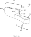
- Figures 2A and 2B illustrate perspective views of a fiber separation tool 200 in accordance with embodiments of the present invention, wherein Figure 2A is a bottom projection view and Figure 2B is a top projection view.
- the fiber separation tool 200 includes a handle portion 202 connected to a head portion 204.
- the widest width of the head portion 204 may be narrower than the widest width of the handle portion.
- the head portion 204 may have a greater vertical length than the vertical length of the handle portion 202.
- the fiber separation tool 200 may be formed as a unitary piece or it may include two or more separately formed pieces that are joined together to form the fiber separation tool 200.
- the fiber separation tool 200 may be formed as an integral monolithic component, for example, using 3-D printing.
- the fiber separation tool 200 may include a left portion and a right portion, in which the left portion and the right portion are mirror images of each other, and the left portion and the right portion are joined together to form the fiber separation tool 200.
- the left and right portions may include complementary extensions and openings, such that the left and right portions mate when pressed or snapped together.
- the left and right portions may be adhered together using a suitable adhesive.
- the fiber separation tool 200 is sized to fit in a service technician's tool belt or tool kit. It may be formed of one or more materials that are lightweight and do not add significant weight to the service technician's tools. In particular embodiments, the fiber separation tool 200 is a handheld tool.
- the handle portion 202 of the fiber separation tool 200 includes a pivot point 201.
- the handle portion 202 may be formed from plastic, resin, nylon, polypropylene, polylactic acid, carbon, or any other suitably rigid material.
- the rigid material is a lightweight material.
- the handle portion 202 may be elongated in a longitudinal direction from the head portion 204. An end of the handle portion 202 may be rounded.
- the circumferential size of the handle portion 202 may be any size allowing for a comfortable grip by a user, for example, a service technician.
- the handle portion 202 may be smooth or it may be textured to allow for a more secure grip by the user.
- the handle portion 202 may also include indentions to assist in providing a comfortable and secure grip by the user.
- the handle portion 202 includes a bearing hole 211 that may receive a removable handle 217 (see Figure 3 ).
- the bearing hole 211 may be a through hole extending completely through the handle portion 202.
- the bearing hole 211 may be any suitable size and shape to receive and stably hold the removable handle 217 during use of the fiber separation tool 200.
- the bearing hole 211 and the handle 217 may have the same shape or different shapes.
- the handle 217 may be formed from steel, alloy steel, carbon fiber, stainless steel 304, 316L, duplex stainless steel 2205, hardened carbon steel, or any other suitable material.
- a user may grip or hold the handle portion 202 while using the fiber separation tool 200. In another embodiment, the user may grip or hold the handle 217 while using the fiber separation tool 200.
- the head portion 204 includes a fin 203, a hook tip 205, a blade holder 207, an opening 208, a lip 209, and a cavity 210.
- the head portion 204 may be formed from plastic, resin, nylon, polypropylene, polylactic acid, carbon, or any other suitably rigid material.
- the rigid material is a lightweight material.
- the fin 203 may include a thin, elongated portion extending longitudinally from the handle portion 202.
- a first end of the fin 203 opposite the handle portion 202 may be a convex shape.
- the first end of the fin 203 may be rounded, or it may be any other shape suitable for moving between optical fibers 150 without causing damage to the optical fibers 150.
- a second end of the fin 203, opposite the first end, includes a concave portion.
- a first end of the concave portion contacts the handle portion 202.
- a second, opposite, end of the concave portion forms the hook tip 205.
- the hook tip 205 may be a rounded region, but is more preferably a pointed region or other shaped region suitable to assist in placement of the hook tip 205 between neighboring optical fibers 150.
- the hook tip 205 is placed between two neighboring optical fibers 150 where bonding material 140 is not present (see, e.g., description of step S105 of Figure 1D ).
- the lip 209 is formed on both sides of the concave portion between the first end and the second end. A portion of the blade holder 207 is visible within the lip 209, such that the lip 209 is formed at each side of the visible portion of the blade holder 207. In an embodiment, the blade holder 207 may be centered in the concave portion such that equal amounts of the lip 209 are provided to the left and right of the opening for the blade holder 207.
- the blade holder 207 is configured to hold a blade 213 (see Figures 3 and 4 ) in a fixed position where a predetermined portion of the blade 213 protrudes from the blade holder 207.
- the other portion of the blade 213 is housed in a cavity 210 in the fin 203.
- the cavity 210 is disposed within the fin 203.
- the cavity 210 has a shape and size to accommodate and provide support for the blade 213.
- the blade 213 may be inserted into blade holder 207 such that a sharp edge of the blade 213 protrudes from the blade holder 207.
- the blade 213 may be replaceable or it may be permanently affixed in the fin 203 in various embodiments.
- the blade 213 may be any suitable material for slicing through the bonding material 140.
- the blade 213 is made of stainless steel.
- the blade 213 may comprise steel, or alloys of steel comprising carbon, chromium, cobalt, manganese, nickel, molybdenum, tungsten, and/or vanadium.
- the blade 213 may comprise other metal alloys, or carbon based materials, e.g., comprising graphite.
- the blade 213 may be any suitable shape for being securely held in the blade holder 207 during use of the fiber separation tool 200.
- the blade 213 is placed in the cavity 210 through an opening 208 formed in the head portion 204.
- the opening 208 may be formed along an upper edge of the head portion 204 over the cavity 210.
- the opening 208 may have a shape and size similar to the shape and size of the blade 213.
- the blade 213 may be inserted into the opening 208, so that it drops smoothly into the cavity 210 and a portion of the blade 213 is exposed through the opening of the blade holder 207.
- the blade 213 may be removed by, for example, turning the fiber separation tool 200 over to allow the blade 213 to drop back through the opening 208.
- the fiber separation tool 200 may include a mechanism (not shown) for safe handling of the blade 213.
- a mechanism may be provided to allow a user to slide the blade 213 in a longitudinal direction towards the first end of the fin 203, so that no portion of the blade 213 protrudes from the blade holder 207 when the fiber separation tool 200 is not in use. That is, the blade 213 may be safely and fully encased within the cavity 210 in fin 203.
- the mechanism would also allow the user to slide the blade 213 in the longitudinal direction towards the second end of the fin 203, so that a portion of the blade 213 protrudes from the blade holder 207 when the fiber separation tool is ready for use.
- the fiber separation tool 200 may include a blade cover or guard (not shown) to cover the exposed portion of the blade 213 when the blade 213 is present in the blade holder 207, but the fiber separation tool 200 is not in use.
- the lip 209 has a thickness sufficient to prevent the optical fibers 150 from contacting the blade 213 placed in the blade holder 207. Accordingly, the lip 209 reduces the probability of the blade 213 contacting the optical fibers 150 by separating them to each side of the fin 203 as the blade 213 is moved toward the bonding material 140.
- the fin 203 of the fiber separation tool 200 maintains a parallel orientation with respect to the optical fibers 150 when in use. This helps to reduce the probability that one or more of the optical fibers 150 contacts the blade 213 during use of the fiber separation tool 200.
- the pivot point 201 may allow for the fin 203 to freely control the direction of the blade 213 and for the fiber separation tool 200 to maintain alignment with the optical fibers 150 of the flexible ribbon 100 being separated.
- Figure 4 illustrates a fiber separation tool 200 separating neighboring optical fibers of a flexible ribbon in accordance with embodiments of the present invention.
- a flexible ribbon 100 is arranged where the plurality of optical fibers 150 are parallel to one another, for example, as shown in Figure 1A . Two adjacent optical fibers from the optical fibers 150 are illustrated as being separated.
- the hook tip 205 is inserted between the selected optical fibers 150 at a surface between adjacent optical fibers 150, e.g., in a region free of any bonding material 140.
- the hook tip 205 ensures a correct setup and alignment of the adjacent optical fibers 150 before the blade based cutting is performed.
- the fiber separation tool 200 is then pulled along the length of the optical fibers 150 until a segment of the bonding material 140 is reached.
- the blade 213 makes contact with the bonding material 140 and cuts smoothly through the bonding material 140 to separate the adjacent optical fibers 150.
- the adjacent optical fibers 150 are separated to each side of the head portion 204 as the fiber separation tool 200 continues its movement toward a next region of the bonding material 140, if any.
- the fiber separation tool 200 assists in proper optical fiber separation to reduce the probability of the blade 213 damaging the optical fibers 150.
- the pivot point 201 may allow the fin 203 to freely control the direction of the blade 213 and to maintain alignment with the optical fibers 150 being separated.
- the fin 203 ensures that the blade 213 remains parallel along the path of the flexible ribbon 100.
- the blade 213 slices through the bonding material 140 by, e.g., creating a high stress zone that initiates a cohesive failure within the bonding material (i.e. the bonding material breaks without causing damage to the coating or ink layers of the optical fibers).
- the lip 209 surrounding the blade 213 guides the optical fibers 150 away from the blade 213 as it travels along the flexible ribbon 100.
- a method for separating optical fibers from an intermittently bonded optical fiber ribbon includes creating a high stress zone within a bonding region to initiate cohesive failure of the bonding region without causing damage to the coating of the optical fibers.
- a fiber separation tool composed of a rigid material.
- the fiber separation tool includes a blade holder.
- the blade holder houses a blade and exposes a cutting edge of the blade.
- a method of using a fiber separation tool includes inserting a hook tip between selected fibers, guiding the fiber separation tool in a direction parallel to the length of the fibers, controlling the fiber separation tool using a pivot point, introducing a blade to a bonding material to initiate a cohesive failure within the bonding material, and maintaining a distance between the blade and the fibers.
Landscapes
- Physics & Mathematics (AREA)
- General Physics & Mathematics (AREA)
- Optics & Photonics (AREA)
- Light Guides In General And Applications Therefor (AREA)
Abstract
An optical fiber separation tool is provided. The optical fiber separation tool includes a fin configured to maintain the optical fiber separation tool in a parallel orientation with respect to a plurality of optical fibers, a hook tip at a first end of the fin, wherein the hook tip is configured to separate the plurality of optical fibers, a blade disposed in the fin above the hook tip, wherein a portion of a cutting edge of the blade protrudes from a blade opening in the fin, and wherein the blade is configured to slice through a bonding material connecting the plurality of optical fibers, a lip at each side of the blade opening, wherein the lip is configured to prevent individual optical fibers of the plurality of optical fibers from contacting the blade, and a pivot point configured to guide the optical fiber separation tool between the individual optical fibers.
Description
- The present invention relates generally to a method of separating optical fibers and an optical fiber separation tool, and, in particular embodiments, to a method of separating optical fibers using a fiber separation tool.
- Optical fibers are very small diameter glass strands capable of transmitting an optical signal. Optical cables typically include many optical ribbons bundled together as a single cable. Each optical ribbon may include several optical fibers.
- Optical fibers provide advantages over conventional communication lines. Optical-fiber communication networks can transmit significantly more information at significantly higher speeds than is possible with traditional wire-based networks. Optical cables are therefore widely used in long distance communication and have replaced other technologies such as satellite communication, standard wire communication, etc. Besides long distance communication, optical fibers are also used in many applications such as medicine, aviation, computer data servers, etc.
- With the continued growth of optical cables across multiple applications, and the increased demand for faster transmission of larger amounts of information, the thickness of the optical cables is increasing due to an increase in the number of optical fibers included in each cable. The large number of optical fibers makes the process of separating the optical fibers tedious and time-consuming. The traditional process also results in damage to the optical fibers, for example, by a service technician cutting through the thin optical fibers or damaging the coating or ink layers of the optical fibers.
- In accordance with an embodiment of the present invention, a fiber separation tool includes a fin configured to maintain the fiber separation tool in a parallel orientation with respect to a plurality of fibers, and a hook tip at a first end of the fin, wherein the hook tip is configured to separate the plurality of fibers. A blade is disposed in the fin above the hook tip, a portion of a cutting edge of the blade protrudes from a blade opening in the fin, and the blade is configured to slice through a bonding material connecting the plurality of fibers. The fiber separation tool further includes a lip at each side of the blade opening, wherein the lip is configured to prevent individual fibers of the plurality of fibers from contacting the blade, and a pivot point configured to guide the fiber separation tool between the individual fibers.
- In accordance with an embodiment of the present invention, a method of using a fiber separation tool includes arranging an array of fibers side-by-side, wherein each fiber is connected to at least one other neighboring fiber with a bonding material, and wherein the bonding material is intermittently dispersed between each fiber. The method further includes selecting two neighboring fibers from the array of fibers, inserting a hook point of the fiber separation tool between the selected fibers at a region free of the bonding material, guiding the fiber separation tool in a direction parallel to a length of the selected fibers, contacting the bonding material connecting the selected fibers with a blade of the fiber separation tool, and directing the fibers to each side of the fiber separation tool.
- In accordance with an embodiment of the present invention, a fiber separation tool includes a head portion including a fin having a first vertical surface, a hook tip at a bottom edge of the first vertical surface, a blade opening in the first vertical surface above the hook tip, and a lip on each side of the blade opening on the first vertical surface. The fiber separation tool further includes a handle portion including a pivot point and a bearing hole.
- For a more complete understanding of the present invention, and the advantages thereof, reference is now made to the following descriptions taken in conjunction with the accompanying drawings, in which:
-
Figure 1A illustrates a projection view of an array of optical fibers forming a flexible ribbon; -
Figure 1B illustrates a corresponding cross-sectional area of the array of optical fibers illustrated inFigure 1A ; -
Figure 1C illustrates a buffer tube encasing multiple flexible ribbons according toFigure 1A ; -
Figures 1D and 1E illustrate a process for separating neighboring optical fibers of a flexible ribbon according to embodiments of the present invention; -
Figures 2A and2B illustrate perspective views of a fiber separation tool according to embodiments of the present invention; -
Figure 3 illustrates a fiber separation tool with a handle according to embodiments of the present invention; and -
Figure 4 illustrates a fiber separation tool separating neighboring optical fibers of a flexible ribbon according to embodiments of the present invention. - The making and using of the presently preferred embodiments are discussed in detail below. It should be appreciated, however, that the present invention provides many applicable inventive concepts that can be embodied in a wide variety of specific contexts. The specific embodiments discussed are merely illustrative of specific ways to make and use the invention, and do not limit the scope of the invention.
- Optical fibers are very small diameter glass strands capable of transmitting an optical signal. Optical cables typically include many optical ribbons bundled together as a single cable. Each optical ribbon may include any number of optical fibers.
- Typically, the optical cable is shipped intact to the field for installation. Once there, a service technician is required to splice the cable and separate the optical ribbon into individual optical fibers. These optical fibers may, for example, then be inserted into a suitable interconnection. However, because each optical cable has a large number of optical fibers, and the number of optical fibers is likely to continue increasing, this process can be both tedious and time-consuming.
- It is also possible for the service technician to accidentally cut through the thin optical fibers while separating them. Also, when separating one or more optical fibers from an optical ribbon, the coating or ink layers of the optical fibers may get damaged. For example, optical fibers in flexible ribbons may be joined by a bonding material having a bonding property that exceeds the cohesive strength of the fiber coating. As a result, pulling the optical fibers apart or separating them using traditional tools may cause a break in the fiber coating instead of in the bonding material as intended.
- Accordingly, there is a need for an improved tool that can separate the optical fibers without damaging the optical fibers and without need for specialized training to allow service technicians of varying levels of experience to easily and efficiently separate the optical fibers without damaging the optical fibers.
- Various embodiments of the present invention disclose a fiber separation tool that can be used to safely separate optical fibers of an optical ribbon and methods of using the same.
-
Figure 1A illustrates a projection view of an array of optical fibers forming a flexible ribbon, andFigure 1B illustrates a corresponding cross-sectional area of the array of optical fibers illustrated inFigure 1A . -
Figure 1A illustrates aflexible ribbon 100, such as a flexible ribbon cable. Theflexible ribbon 100 includes a plurality ofoptical fibers 150, such as a first, a second, a third, a fourth, a fifth, and a sixth optical fiber 151-156. Though sixoptical fibers 150 are illustrated inFigure 1A , more or fewer optical fibers may be included in theflexible ribbon 100. Theoptical fibers 150 each have a coating or ink layer. - The optical fibers 151-156 are arranged parallel to one another and are connected to neighboring optical fibers 151-156 using a
bonding material 140. The bondingmaterial 140 may be a substantially cured ribbon-matrix material having elongation-to-break and modulus characteristics that promote reversible folding and/or rolling of theflexible ribbon 100. Thebonding material 140 may include ultraviolet (UV) acrylate. In other embodiments, thebonding material 140 may include low-modulus elastomers and silicones, such as UV-curable silicones and RTV silicones (i.e., room-temperature-vulcanization silicone). The UV-cured silicones have some advantages over RTV silicones, including faster curing and reduced shrinkage. In addition, unlike UV-cured silicones, RTV silicones require exposure to humidity and high temperatures for extended time periods and can generate unwanted byproducts (e.g., acetic acid) during curing. Suitable UV-curable silicones include LOCTITE® SI 5240™ UV-cured silicone and Addisil UV-cured silicones (e.g., UV 50 EX, UV 60 EX, and UV 70 EX). The bondingmaterial 140 is not limited to these materials; other materials for bonding optical fibers as known to persons of ordinary skill in the art may also be used. - The bonding
material 140 is arranged across theflexible ribbon 100 so as to selectively leave a large surface of theoptical fibers 150 free of thebonding material 140. For example, in the cross-sectional view ofFigure 1B , thebonding material 140 is formed between the firstoptical fiber 151 and the secondoptical fiber 152, and no bonding material is formed between the other optical fibers 152-156 at this cross-section. Consequently,optical fibers 150 maintain a large degree of freedom and can be effectively folded or otherwise randomly positioned when theflexible ribbon 100 is subjected to external stress, for example. In various embodiments, theoptical fibers 150 can be folded into a densely packed configuration. In one or more embodiments, the foldedoptical fibers 150 may have a non-circular or irregular shape. -
Figure 1C illustrates a buffer tube encasing multiple flexible ribbons in accordance with an embodiment of the present invention. Abuffer tube 110 encases multipleflexible ribbons 100. Theflexible ribbons 100 are enclosed by abuffer tube jacket 160. In one or more embodiments, thebuffer tube jacket 160 comprises polypropylene. In other embodiments, thebuffer tube jacket 160 comprises cellular polypropylene, polyethylene, nylon, or other materials. In addition, theflexible ribbons 100 may be dispersed within agel 170 that allows theflexible ribbons 100 to move around relative to each other. Of course, an optical cable (not shown) may comprise a plurality ofbuffer tubes 110. -
Figures 1D and 1E illustrate a process for separating neighboring optical fibers of a flexible ribbon according to embodiments of the present invention. -
Figure 1D illustrates aflexible ribbon 100 after it has been extracted and separated from an optical cable. For example, theflexible ribbon 100 may be extracted from an optical cable by separating itsbuffer tube 110 fromother buffer tubes 110 and then cutting through thebuffer tube jacket 160 of thebuffer tube 110. Alternatively, the process for extracting and separating flexible ribbons from an optical cable may be performed by any method or process known to a person of ordinary skill in the art. -
Figure 1D illustrates a first separation step S105 for separating optical fibers 150 (such as optical fibers 151-156) from each other. The separation step S105 may start at any region of theflexible ribbon 100 where the surface between adjacentoptical fibers 150 is free ofbonding material 140. During step S105, theoptical fibers 150 may be separated and spread out. In an embodiment, a service technician may begin the process of spreading theoptical fibers 150 manually when placing theflexible ribbon 100 in a configuration such as that shown inFigure 1D . As will be further described herein, a separation tool also may be used to separate theoptical fibers 150. In particular, the separation tool may facilitate the movement of theoptical fibers 150 around a blade of the separation tool so that individual ones of theoptical fibers 150 are not cut or damaged by the blade of the separation tool. -
Figure 1E illustrates a second separation step S107 in which thebonding material 140 is cut through causing adjacent ones of theoptical fibers 150 to separate without damaging theoptical fibers 150. As will be further described herein, a separation tool enables cutting through thebonding material 140 attaching adjacent ones of theoptical fibers 150 without cutting or damaging theoptical fibers 150. -
Figures 2A and2B illustrate perspective views of afiber separation tool 200 in accordance with embodiments of the present invention, whereinFigure 2A is a bottom projection view andFigure 2B is a top projection view. - Referring to
Figure 2A , thefiber separation tool 200 includes ahandle portion 202 connected to ahead portion 204. In an embodiment, the widest width of thehead portion 204 may be narrower than the widest width of the handle portion. In an embodiment, thehead portion 204 may have a greater vertical length than the vertical length of thehandle portion 202. Thefiber separation tool 200 may be formed as a unitary piece or it may include two or more separately formed pieces that are joined together to form thefiber separation tool 200. - In an embodiment, the
fiber separation tool 200 may be formed as an integral monolithic component, for example, using 3-D printing. In an embodiment, thefiber separation tool 200 may include a left portion and a right portion, in which the left portion and the right portion are mirror images of each other, and the left portion and the right portion are joined together to form thefiber separation tool 200. In an embodiment, the left and right portions may include complementary extensions and openings, such that the left and right portions mate when pressed or snapped together. In another embodiment, the left and right portions may be adhered together using a suitable adhesive. - In particular embodiments, the
fiber separation tool 200 is sized to fit in a service technician's tool belt or tool kit. It may be formed of one or more materials that are lightweight and do not add significant weight to the service technician's tools. In particular embodiments, thefiber separation tool 200 is a handheld tool. - The
handle portion 202 of thefiber separation tool 200 includes apivot point 201. Thehandle portion 202 may be formed from plastic, resin, nylon, polypropylene, polylactic acid, carbon, or any other suitably rigid material. In particular embodiments, the rigid material is a lightweight material. Thehandle portion 202 may be elongated in a longitudinal direction from thehead portion 204. An end of thehandle portion 202 may be rounded. The circumferential size of thehandle portion 202 may be any size allowing for a comfortable grip by a user, for example, a service technician. Thehandle portion 202 may be smooth or it may be textured to allow for a more secure grip by the user. Thehandle portion 202 may also include indentions to assist in providing a comfortable and secure grip by the user. - In some embodiments, the
handle portion 202 includes abearing hole 211 that may receive a removable handle 217 (seeFigure 3 ). Thebearing hole 211 may be a through hole extending completely through thehandle portion 202. Thebearing hole 211 may be any suitable size and shape to receive and stably hold theremovable handle 217 during use of thefiber separation tool 200. Thebearing hole 211 and thehandle 217 may have the same shape or different shapes. Thehandle 217 may be formed from steel, alloy steel, carbon fiber, stainless steel 304, 316L, duplex stainless steel 2205, hardened carbon steel, or any other suitable material. - In an embodiment, a user may grip or hold the
handle portion 202 while using thefiber separation tool 200. In another embodiment, the user may grip or hold thehandle 217 while using thefiber separation tool 200. - As illustrated in
Figures 2A and2B , thehead portion 204 includes afin 203, ahook tip 205, ablade holder 207, anopening 208, alip 209, and acavity 210. Thehead portion 204 may be formed from plastic, resin, nylon, polypropylene, polylactic acid, carbon, or any other suitably rigid material. In particular embodiments, the rigid material is a lightweight material. - The
fin 203 may include a thin, elongated portion extending longitudinally from thehandle portion 202. A first end of thefin 203 opposite thehandle portion 202 may be a convex shape. In an embodiment, the first end of thefin 203 may be rounded, or it may be any other shape suitable for moving betweenoptical fibers 150 without causing damage to theoptical fibers 150. A second end of thefin 203, opposite the first end, includes a concave portion. A first end of the concave portion contacts thehandle portion 202. A second, opposite, end of the concave portion forms thehook tip 205. - The
hook tip 205 may be a rounded region, but is more preferably a pointed region or other shaped region suitable to assist in placement of thehook tip 205 between neighboringoptical fibers 150. Thehook tip 205 is placed between two neighboringoptical fibers 150 wherebonding material 140 is not present (see, e.g., description of step S105 ofFigure 1D ). - The
lip 209 is formed on both sides of the concave portion between the first end and the second end. A portion of theblade holder 207 is visible within thelip 209, such that thelip 209 is formed at each side of the visible portion of theblade holder 207. In an embodiment, theblade holder 207 may be centered in the concave portion such that equal amounts of thelip 209 are provided to the left and right of the opening for theblade holder 207. - The
blade holder 207 is configured to hold a blade 213 (seeFigures 3 and4 ) in a fixed position where a predetermined portion of theblade 213 protrudes from theblade holder 207. The other portion of theblade 213 is housed in acavity 210 in thefin 203. Thecavity 210 is disposed within thefin 203. Thecavity 210 has a shape and size to accommodate and provide support for theblade 213. - As illustrated in
Figure 3 , theblade 213 may be inserted intoblade holder 207 such that a sharp edge of theblade 213 protrudes from theblade holder 207. Theblade 213 may be replaceable or it may be permanently affixed in thefin 203 in various embodiments. Theblade 213 may be any suitable material for slicing through thebonding material 140. In one embodiment, theblade 213 is made of stainless steel. In other embodiments, theblade 213 may comprise steel, or alloys of steel comprising carbon, chromium, cobalt, manganese, nickel, molybdenum, tungsten, and/or vanadium. In other embodiments, theblade 213 may comprise other metal alloys, or carbon based materials, e.g., comprising graphite. Theblade 213 may be any suitable shape for being securely held in theblade holder 207 during use of thefiber separation tool 200. - In an embodiment, the
blade 213 is placed in thecavity 210 through anopening 208 formed in thehead portion 204. Theopening 208 may be formed along an upper edge of thehead portion 204 over thecavity 210. Theopening 208 may have a shape and size similar to the shape and size of theblade 213. In an embodiment, theblade 213 may be inserted into theopening 208, so that it drops smoothly into thecavity 210 and a portion of theblade 213 is exposed through the opening of theblade holder 207. Theblade 213 may be removed by, for example, turning thefiber separation tool 200 over to allow theblade 213 to drop back through theopening 208. - In some embodiments, the
fiber separation tool 200 may include a mechanism (not shown) for safe handling of theblade 213. For example, a mechanism may be provided to allow a user to slide theblade 213 in a longitudinal direction towards the first end of thefin 203, so that no portion of theblade 213 protrudes from theblade holder 207 when thefiber separation tool 200 is not in use. That is, theblade 213 may be safely and fully encased within thecavity 210 infin 203. The mechanism would also allow the user to slide theblade 213 in the longitudinal direction towards the second end of thefin 203, so that a portion of theblade 213 protrudes from theblade holder 207 when the fiber separation tool is ready for use. - In some embodiments, the
fiber separation tool 200 may include a blade cover or guard (not shown) to cover the exposed portion of theblade 213 when theblade 213 is present in theblade holder 207, but thefiber separation tool 200 is not in use. - The
lip 209 has a thickness sufficient to prevent theoptical fibers 150 from contacting theblade 213 placed in theblade holder 207. Accordingly, thelip 209 reduces the probability of theblade 213 contacting theoptical fibers 150 by separating them to each side of thefin 203 as theblade 213 is moved toward thebonding material 140. - The
fin 203 of thefiber separation tool 200 maintains a parallel orientation with respect to theoptical fibers 150 when in use. This helps to reduce the probability that one or more of theoptical fibers 150 contacts theblade 213 during use of thefiber separation tool 200. In some embodiments, thepivot point 201 may allow for thefin 203 to freely control the direction of theblade 213 and for thefiber separation tool 200 to maintain alignment with theoptical fibers 150 of theflexible ribbon 100 being separated. -
Figure 4 illustrates afiber separation tool 200 separating neighboring optical fibers of a flexible ribbon in accordance with embodiments of the present invention. - A
flexible ribbon 100 is arranged where the plurality ofoptical fibers 150 are parallel to one another, for example, as shown inFigure 1A . Two adjacent optical fibers from theoptical fibers 150 are illustrated as being separated. - The
hook tip 205 is inserted between the selectedoptical fibers 150 at a surface between adjacentoptical fibers 150, e.g., in a region free of anybonding material 140. Thus, thehook tip 205 ensures a correct setup and alignment of the adjacentoptical fibers 150 before the blade based cutting is performed. Thefiber separation tool 200 is then pulled along the length of theoptical fibers 150 until a segment of thebonding material 140 is reached. Theblade 213 makes contact with thebonding material 140 and cuts smoothly through thebonding material 140 to separate the adjacentoptical fibers 150. The adjacentoptical fibers 150 are separated to each side of thehead portion 204 as thefiber separation tool 200 continues its movement toward a next region of thebonding material 140, if any. - In an embodiment, the
fiber separation tool 200 assists in proper optical fiber separation to reduce the probability of theblade 213 damaging theoptical fibers 150. Thepivot point 201 may allow thefin 203 to freely control the direction of theblade 213 and to maintain alignment with theoptical fibers 150 being separated. Thefin 203 ensures that theblade 213 remains parallel along the path of theflexible ribbon 100. As thefiber separation tool 200 encounters thebonding material 140, theblade 213 slices through thebonding material 140 by, e.g., creating a high stress zone that initiates a cohesive failure within the bonding material (i.e. the bonding material breaks without causing damage to the coating or ink layers of the optical fibers). Thelip 209 surrounding theblade 213 guides theoptical fibers 150 away from theblade 213 as it travels along theflexible ribbon 100. - In accordance with an embodiment of the present invention, a method for separating optical fibers from an intermittently bonded optical fiber ribbon includes creating a high stress zone within a bonding region to initiate cohesive failure of the bonding region without causing damage to the coating of the optical fibers.
- In accordance with another embodiment of the present invention, a fiber separation tool composed of a rigid material is provided. The fiber separation tool includes a blade holder. The blade holder houses a blade and exposes a cutting edge of the blade.
- In accordance with another embodiment of the present invention, a method of using a fiber separation tool includes inserting a hook tip between selected fibers, guiding the fiber separation tool in a direction parallel to the length of the fibers, controlling the fiber separation tool using a pivot point, introducing a blade to a bonding material to initiate a cohesive failure within the bonding material, and maintaining a distance between the blade and the fibers.
- While this invention has been described with reference to illustrative embodiments, this description is not intended to be construed in a limiting sense. Various modifications and combinations of the illustrative embodiments, as well as other embodiments of the invention, will be apparent to persons skilled in the art upon reference to the description. It is therefore intended that the appended claims encompass any such modifications or embodiments.
Claims (15)
- A fiber separation tool (200) comprising:a fin (203) configured to maintain the fiber separation tool in a parallel orientation with respect to a plurality of fibers (150);a hook tip (205) at a first end of the fin, wherein the hook tip is configured to separate the plurality of fibers;a blade (213) disposed in the fin above the hook tip, wherein a portion of a cutting edge of the blade protrudes from a blade opening in the fin, and wherein the blade is configured to slice through a bonding material connecting the plurality of fibers;a lip (209) at each side of the blade opening, wherein the lip is configured to prevent individual fibers of the plurality of fibers from contacting the blade; anda pivot point (201) configured to guide the fiber separation tool between the individual fibers.
- The fiber separation tool according to claim 1, wherein the blade opening is centered in the lip, and wherein the blade is partially enclosed in a cavity (210) in the fin.
- The fiber separation tool according to claim 1, wherein the blade is in a fixed position in the fiber separation tool.
- The fiber separation tool according to claim 1, wherein the blade is removable.
- The fiber separation tool according to any one or more of the preceding claims, further comprising:a bearing hole (211); anda removable handle (217) disposed in the bearing hole.
- The fiber separation tool according to any one or more of the preceding claims, further comprising an opening in a top surface of the fiber separation tool, the opening configured to receive the blade, especially further comprising a cavity in the fin disposed below the opening in the top surface of the fiber separation tool, wherein the cavity is configured to hold the blade after the blade is received by the opening.
- The fiber separation tool according to any one or more of the preceding claims, further comprising:a head portion (204) comprising:said fin having a first vertical surface;said hook tip at a bottom edge of the first vertical surface;said blade opening in the first vertical surface above the hook tip; andsaid lip on each side of the blade opening on the first vertical surface; anda handle portion (202) comprising:said pivot point; andsaid bearing hole.
- The fiber separation tool according to claim 7, wherein the fin comprises a second vertical surface opposite the first vertical surface, and wherein the first vertical surface has a concave shape and the second vertical surface has a convex shape.
- The fiber separation tool according to any one or more of claims 7-8, further comprising a handle detachably connected to the handle portion, wherein the handle is configured to connect to the bearing hole.
- The fiber separation tool according to any one or more of claims 7-9, further comprising:an opening in a top surface of the fiber separation tool;a cavity disposed in the fin below the opening in the top surface; anda blade disposed in the cavity, wherein the blade is sized to fit into the opening and to slide into the cavity, and wherein a portion of the blade protrudes through the blade opening.
- The fiber separation tool according to any one or more of claims 7-10, wherein the hook tip is configured to slide between fibers, the blade is configured to slice through a bonding material attaching the fibers to each other, and the lip is configured to provide a distance between the fibers and the blade.
- A method of separating optical fibers using a fiber separation tool according to any one or more of the preceding claims , the method comprising:arranging an array of fibers side-by-side, wherein each fiber is connected to at least one other neighboring fiber with a bonding material, and wherein the bonding material is intermittently dispersed between each fiber;selecting two neighboring fibers from the array of fibers;inserting a hook point of the fiber separation tool between the selected fibers at a region free of the bonding material;guiding the fiber separation tool in a direction parallel to a length of the selected fibers;contacting the bonding material connecting the selected fibers with a blade of the fiber separation tool; anddirecting the fibers to each side of the fiber separation tool.
- The method according to claim 12, further comprising separating a flexible ribbon from a buffer tube of an optical cable prior to arranging the array of fibers side-by-side.
- The method according to any one or more of claims 12-13, further comprising maintaining a minimum distance between the blade and the selected fibers, wherein the minimum distance is based on a thickness of a lip of the fiber separation tool.
- The method according to any one or more of claims 12-14, wherein guiding the fiber separation tool comprises moving the fiber separation tool such that the fibers pass along sides of a fin of the fiber separation tool.
Applications Claiming Priority (1)
| Application Number | Priority Date | Filing Date | Title |
|---|---|---|---|
| US16/810,278 US11460636B2 (en) | 2020-03-05 | 2020-03-05 | Flexible ribbon fiber separation tool |
Publications (1)
| Publication Number | Publication Date |
|---|---|
| EP3876005A1 true EP3876005A1 (en) | 2021-09-08 |
Family
ID=74556761
Family Applications (1)
| Application Number | Title | Priority Date | Filing Date |
|---|---|---|---|
| EP21155500.8A Withdrawn EP3876005A1 (en) | 2020-03-05 | 2021-02-05 | Flexible ribbon fiber separation tool |
Country Status (3)
| Country | Link |
|---|---|
| US (1) | US11460636B2 (en) |
| EP (1) | EP3876005A1 (en) |
| AU (1) | AU2021200803A1 (en) |
Citations (4)
| Publication number | Priority date | Publication date | Assignee | Title |
|---|---|---|---|---|
| JPH11198089A (en) * | 1998-01-09 | 1999-07-27 | Hitachi Cable Ltd | Tape-type optical fiber separation tool |
| US20070263964A1 (en) * | 2006-05-11 | 2007-11-15 | Cody Joseph T | Fiber optic distribution cables and structures therefore |
| US20130220097A1 (en) * | 2012-02-29 | 2013-08-29 | Joshua Douglas Raker | Cable preparation tool and methods therefor |
| JP2015099316A (en) * | 2013-11-20 | 2015-05-28 | 株式会社フジクラ | Attachment capable of being attached to and detached from an optical fiber tape dividing tool and optical fiber tape dividing method |
Family Cites Families (10)
| Publication number | Priority date | Publication date | Assignee | Title |
|---|---|---|---|---|
| US3355803A (en) * | 1965-10-20 | 1967-12-05 | Whitney Blake Co | Tweezer-like tool for longitudinally slitting the web connecting a joined conductor-pair |
| US3839788A (en) * | 1971-07-06 | 1974-10-08 | C Addis | Eviscerating and skinning knife |
| US5142780A (en) * | 1990-03-22 | 1992-09-01 | Brewer George I | Electric cable stripping tool with claw |
| US20050066466A1 (en) * | 2003-08-11 | 2005-03-31 | Gary Butterfield | Super scraper |
| CN201392417Y (en) | 2009-03-12 | 2010-01-27 | 江苏通鼎光电股份有限公司 | Optical fiber ribbon stripper |
| US20100319199A1 (en) | 2009-06-17 | 2010-12-23 | Tyco Electronics Corporation | Cutters for Accessing a Fiber within a Fiber Optic Cable to Splice Thereto and Tools and Methods Using the Same |
| JP4968754B1 (en) * | 2011-03-30 | 2012-07-04 | 昭和電線ケーブルシステム株式会社 | Optical fiber ribbon and optical cable |
| WO2013043966A1 (en) * | 2011-09-21 | 2013-03-28 | Afl Telecommunications Llc | Optical trunk cable |
| JP5391296B2 (en) * | 2012-03-02 | 2014-01-15 | 株式会社フジクラ | Optical fiber tape core and optical fiber cable storing the optical fiber core |
| US9819161B2 (en) | 2015-03-13 | 2017-11-14 | Jonard Industries Corp. | Tube splitter |
-
2020
- 2020-03-05 US US16/810,278 patent/US11460636B2/en active Active
-
2021
- 2021-02-05 EP EP21155500.8A patent/EP3876005A1/en not_active Withdrawn
- 2021-02-09 AU AU2021200803A patent/AU2021200803A1/en not_active Abandoned
Patent Citations (4)
| Publication number | Priority date | Publication date | Assignee | Title |
|---|---|---|---|---|
| JPH11198089A (en) * | 1998-01-09 | 1999-07-27 | Hitachi Cable Ltd | Tape-type optical fiber separation tool |
| US20070263964A1 (en) * | 2006-05-11 | 2007-11-15 | Cody Joseph T | Fiber optic distribution cables and structures therefore |
| US20130220097A1 (en) * | 2012-02-29 | 2013-08-29 | Joshua Douglas Raker | Cable preparation tool and methods therefor |
| JP2015099316A (en) * | 2013-11-20 | 2015-05-28 | 株式会社フジクラ | Attachment capable of being attached to and detached from an optical fiber tape dividing tool and optical fiber tape dividing method |
Also Published As
| Publication number | Publication date |
|---|---|
| US11460636B2 (en) | 2022-10-04 |
| US20210278593A1 (en) | 2021-09-09 |
| AU2021200803A1 (en) | 2021-09-23 |
Similar Documents
| Publication | Publication Date | Title |
|---|---|---|
| US5295421A (en) | Blade for fiber ribbon stripping | |
| US20250012998A1 (en) | Handheld tool for removing a wire from within an optical cable | |
| JP2004206048A (en) | Optical fiber ribbon and manufacturing method thereof | |
| US20100319199A1 (en) | Cutters for Accessing a Fiber within a Fiber Optic Cable to Splice Thereto and Tools and Methods Using the Same | |
| KR20230032891A (en) | Optical Cable | |
| US11460636B2 (en) | Flexible ribbon fiber separation tool | |
| KR20240097810A (en) | Optical Cable | |
| US20060002669A1 (en) | Optical fiber array with an intermittent profile and method for manufacturing the same | |
| WO2021049157A1 (en) | Optical fiber arrangement method, optical fiber splicing method, production method for optical fiber tape with connector, and intermittently-connected optical fiber tape | |
| JP5354751B2 (en) | Single fiber separator for optical fiber tape | |
| US20140090538A1 (en) | Method for stripping long segments of buffered optical fiber and a tool for performing the same | |
| JP3714423B2 (en) | Branching method of optical fiber ribbon, branching tool of optical fiber ribbon, and optical fiber ribbon | |
| US11780103B2 (en) | Fiber ribbon separation tool | |
| JP2005043467A (en) | Fiber optic cable | |
| JP4084363B2 (en) | Separation method of optical fiber ribbon and separation tool set | |
| JP6025693B2 (en) | Attachment capable of being attached to and detached from an optical fiber tape dividing tool and optical fiber tape dividing method | |
| JPH11326645A (en) | Tool and method for removing blanket coating of optical fiber ribbon | |
| JP3530098B2 (en) | Single core separation tool for tape core | |
| EP4556977A1 (en) | Optical fiber ribbon and optical cable | |
| JP5115774B2 (en) | Clamp structure for optical fiber | |
| JP2005227802A (en) | Branching method and branching tool for optical fiber ribbon | |
| JP2003279756A (en) | How to branch optical fiber ribbon | |
| JP2005222080A (en) | Optical fiber ribbon and manufacturing method thereof | |
| JP2000028830A (en) | Workbench for collective coating removal of optical tape core wire and batch coating removal method | |
| JPH11198089A (en) | Tape-type optical fiber separation tool |
Legal Events
| Date | Code | Title | Description |
|---|---|---|---|
| PUAI | Public reference made under article 153(3) epc to a published international application that has entered the european phase |
Free format text: ORIGINAL CODE: 0009012 |
|
| STAA | Information on the status of an ep patent application or granted ep patent |
Free format text: STATUS: THE APPLICATION HAS BEEN PUBLISHED |
|
| AK | Designated contracting states |
Kind code of ref document: A1 Designated state(s): AL AT BE BG CH CY CZ DE DK EE ES FI FR GB GR HR HU IE IS IT LI LT LU LV MC MK MT NL NO PL PT RO RS SE SI SK SM TR |
|
| STAA | Information on the status of an ep patent application or granted ep patent |
Free format text: STATUS: THE APPLICATION IS DEEMED TO BE WITHDRAWN |
|
| 18D | Application deemed to be withdrawn |
Effective date: 20220310 |