EP3875936A1 - State determination device, door control device, state determination method, and state determination program - Google Patents
State determination device, door control device, state determination method, and state determination program Download PDFInfo
- Publication number
- EP3875936A1 EP3875936A1 EP21159615.0A EP21159615A EP3875936A1 EP 3875936 A1 EP3875936 A1 EP 3875936A1 EP 21159615 A EP21159615 A EP 21159615A EP 3875936 A1 EP3875936 A1 EP 3875936A1
- Authority
- EP
- European Patent Office
- Prior art keywords
- door
- driving force
- unit
- transmission mechanism
- load
- Prior art date
- Legal status (The legal status is an assumption and is not a legal conclusion. Google has not performed a legal analysis and makes no representation as to the accuracy of the status listed.)
- Granted
Links
Images



Classifications
-
- G—PHYSICS
- G01—MEASURING; TESTING
- G01M—TESTING STATIC OR DYNAMIC BALANCE OF MACHINES OR STRUCTURES; TESTING OF STRUCTURES OR APPARATUS, NOT OTHERWISE PROVIDED FOR
- G01M99/00—Subject matter not provided for in other groups of this subclass
- G01M99/008—Subject matter not provided for in other groups of this subclass by doing functionality tests
-
- B—PERFORMING OPERATIONS; TRANSPORTING
- B61—RAILWAYS
- B61D—BODY DETAILS OR KINDS OF RAILWAY VEHICLES
- B61D19/00—Door arrangements specially adapted for rail vehicles
-
- B—PERFORMING OPERATIONS; TRANSPORTING
- B61—RAILWAYS
- B61C—LOCOMOTIVES; MOTOR RAILCARS
- B61C17/00—Arrangement or disposition of parts; Details or accessories not otherwise provided for; Use of control gear and control systems
-
- G—PHYSICS
- G01—MEASURING; TESTING
- G01M—TESTING STATIC OR DYNAMIC BALANCE OF MACHINES OR STRUCTURES; TESTING OF STRUCTURES OR APPARATUS, NOT OTHERWISE PROVIDED FOR
- G01M13/00—Testing of machine parts
Definitions
- the present invention relates to a state determination device, a door control device, a state determination method, and a state determination program.
- a state determination device described in Japanese Laid-Open Patent Publication No. 2017-149290 determines the state of a bearing of a railway vehicle by monitoring the bearing and detecting an abnormality in the bearing. This state determination device achieves both early detection of failure of the bearing and prevention of false detections regardless of the usage of the bearing in the railway vehicle.
- the state determination device described in Japanese Laid-Open Patent Publication No. 2017-149290 determines the state of the bearing of the railway vehicle. However, there is no state determination device that determines the state of a transmission mechanism of a door device of a railway vehicle, so that it is desired to provide a state determination device determining the state of the transmission mechanism of the door device of the railway vehicle.
- the present invention has been made in view of the above, and an object of the present invention is to provide a state determination device, a door control device, a state determination method, and a state determination program for determining the state of a transmission mechanism of a door device of a railway vehicle.
- a state determination device includes: a first acquisition unit obtaining driving force information regarding a driving force of a drive unit that drives a door; a second acquisition unit obtaining a load on a transmission mechanism that transmits the driving force of the drive unit to the door; and a determination unit determining the state of the transmission mechanism based on the driving force information obtained by the first acquisition unit and the load obtained by the second acquisition unit.
- the load on the transmission mechanism is likely to have a value different from the driving force information regarding the driving force.
- the determination unit preferably determines the state of the transmission mechanism based on the difference between an upstream load and a downstream load on a transmission path of the driving force that are obtained by the second acquisition unit.
- the determination unit preferably determines the state of the transmission mechanism based on the difference between a load at a portion where directly receives the driving force of the drive unit and a load at a portion of the transmission path of the driving force other than the portion where directly receives the driving force.
- the determination unit preferably determines the state of the transmission mechanism based on a change in load obtained at a same location by the second acquisition unit.
- the determination unit preferably determines the state of the transmission mechanism based on loads obtained at a same location by the second acquisition unit under same conditions.
- a detection unit detecting the load is preferably provided on each of an output portion of the drive unit, a bracket connecting the output portion and the door, and the door.
- the determination unit preferably determines the state of the transmission mechanism when the door is closed.
- the door may be a first door that is one of a plurality of doors provided in a same vehicle
- the second acquisition unit may also obtain a load on a transmission mechanism that transmits a driving force to a second door that is another one of the plurality of doors
- the determination unit preferably determines the state of the transmission mechanism transmitting the driving force to the first door based on the load on the transmission mechanism transmitting the driving force to the first door and the load on the transmission mechanism transmitting the driving force to the second door that are obtained by the second acquisition unit.
- the state determination device may further include a control unit controlling the drive unit. With this configuration, the state of the transmission mechanism transmitting the driving force to the first door can be determined by comparing the load on the transmission mechanism transmitting the driving force to the first door with the load on the transmission mechanism transmitting the driving force to the second door.
- a door control device includes: a first acquisition unit obtaining driving force information regarding a driving force of a drive unit that drives a door; a second acquisition unit obtaining a load on a transmission mechanism that transmits the driving force of the drive unit to the door; a determination unit determining the state of the transmission mechanism based on the driving force information obtained by the first acquisition unit and the load obtained by the second acquisition unit; and a control unit controlling the drive unit.
- the load on the transmission mechanism is likely to have a value different from the driving force information regarding the driving force.
- a state determination method includes: a first acquisition step of obtaining driving force information regarding a driving force of a drive unit that drives a door; a second acquisition step of obtaining a load on a transmission mechanism that transmits the driving force of the drive unit to the door; and a determination step of determining the state of the transmission mechanism based on the driving force information obtained in the first acquisition step and the load obtained in the second acquisition step.
- the load on the transmission mechanism is likely to have a value different from the driving force information regarding the driving force.
- a state determination program causes a computer to perform: a first acquisition step of obtaining driving force information regarding a driving force of a drive unit that drives a door; a second acquisition step of obtaining a load on a transmission mechanism that transmits the driving force of the drive unit to the door; and a determination step of determining the state of the transmission mechanism based on the driving force information obtained in the first acquisition step and the load obtained in the second acquisition step.
- the state determination program may be stored on a computer-readable storage medium.
- the load on the transmission mechanism is likely to have a value different from the driving force information regarding the driving force.
- a door device 10 is provided in, for example, a railroad vehicle and includes a door 11, a drive unit 12 that drives the door 11, and a transmission mechanism 13 that transmits a driving force of the drive unit 12 to the door 11.
- the door 11 is moved to be opened or closed by the driving force of the drive unit 12.
- the drive unit 12 is an electric motor.
- the drive unit 12 reciprocates a piston 12A in an axial direction.
- the piston 12A extends in a width direction of the door 11.
- the piston 12A corresponds to an output portion of the drive unit 12.
- a first coupling member 13A is fixed to an end of the piston 12A, the first coupling member 13A is coupled to the piston 12A and extends in the vertical direction.
- a second coupling member 13B extending in the width direction of the door 11 is fixed to the first coupling member 13A.
- a third coupling member 13C is fixed to the second coupling member 13B and to an upper end of the door 11. That is, the transmission mechanism 13 includes the piston 12A, the first coupling member 13A, the second coupling member 13B, and the third coupling member 13C.
- the element disposed between the drive unit 12 and the door 11 corresponds to the transmission mechanism 13.
- the first coupling member 13A, the second coupling member 13B, and the third coupling member 13C constitute a bracket connecting the piston 12A and the door 11.
- the door device 10 includes a door control device 20, which controls the drive unit 12.
- the door control device 20 opens and closes the door 11 in response to open and close signals respectively, which are control signals output from a general control panel 1 provided in a driver's cab.
- the door control device 20 may be formed of a processor equipped with, for example, a CPU, a RAM, and a ROM, and performs various processes in accordance with a computer program stored on a computer-readable medium, such as a ROM.
- One such computer program is a state determination program that determines the state of the transmission mechanism 13 of the door device 10.
- the door control device 20 determines the state of the transmission mechanism 13 of the door device 10 according to a state determination program stored in a computer-readable medium.
- the door control device 20 is a state determination device that determines the state of the transmission mechanism 13 of the door device 10.
- the door control device 20 includes a control unit 26 that controls the drive unit 12.
- the control unit 26 opens and closes the door 11 by outputting a command value for driving the drive unit 12 in a drive direction corresponding to the open signal or the close signal.
- the control unit 26 supplies, to the drive unit 12, electric power according to a command value relating to the driving force.
- the driving force output from the drive unit 12 is transmitted to the door 11 via the transmission mechanism 13.
- the door control device 20 includes a first acquisition unit 21 for obtaining a command value as driving force information regarding the driving force of the drive unit 12 when the door 11 is driven, and a second acquisition unit 22 for obtaining a load on the transmission mechanism 13 that transmits the driving force of the drive unit 12 to the door 11.
- the first acquisition unit 21 obtains, from the control unit 26, the command value related to the driving force.
- the second acquisition unit 22 obtains the loads detected by a first detection unit 31, a second detection unit 32, a third detection unit 33, a fourth detection unit 34, and a fifth detection unit 35.
- the first to fifth detection units 31 to 35 each include, for example, a strain gauge to detect the load from the strain generated by transmission of the driving force, and output the load to the door control device 20 by wire or wirelessly.
- the first detection unit 31 is attached near the tip end of the piston 12A of the drive unit 12.
- the second detection unit 32 is attached to the first coupling member 13A of the transmission mechanism 13.
- the third detection unit 33 is attached to the second coupling member 13B of the transmission mechanism 13.
- the fourth detection unit 34 is attached to the third coupling member 13C of the transmission mechanism 13.
- the fifth detection unit 35 is attached to a lower side surface of the door 11. The fifth detection unit 35 is able to detect a load at the position farthest from the output of the drive unit 12.
- the door control device 20 includes a determination unit 24 that determines the state of the transmission mechanism 13 based on the command value obtained by the first acquisition unit 21 and the load obtained by the second acquisition unit 22.
- the door control device 20 includes a calculation unit 23 that calculates, from the command value obtained by the first acquisition unit 21 and the load obtained by the second acquisition unit 22, a determination value used by the determination unit 24 for determination.
- the door control device 20 includes a storage unit 25 storing the determination value calculated by the calculation unit 23.
- loads detected by the first to fifth detection units 31 to 35 differ depending on the coupling state between the corresponding member to be detected and the other members, the characteristics of the corresponding member, and the like.
- outputs are calculated from the loads detected by the first to fifth detection units 31 to 35 considering the characteristics of each member, and the state of the transmission mechanism 13 is determined based on the calculated outputs.
- the determination unit 24 determines the state of the transmission mechanism 13 based on the difference between the load based on the command value of the driving force obtained by the first acquisition unit 21 and the load on the transmission path of the driving force that are obtained by the second acquisition unit 22 (hereunder referred to as a determination method A). Specifically, the determination unit 24 determines the state of the transmission mechanism 13 based on a determination value V1 which is hereunder described in detail.
- the calculation unit 23 calculates the determination value V1 that is used by the determination unit 24 for determination.
- the determination unit 24 determines that the state of the transmission mechanism 13 is normal when the determination value V1 calculated by the calculation unit 23 falls within a predetermined range.
- the determination unit 24 determines that there is deterioration in the transmission mechanism 13.
- the deterioration determined by the determination unit 24 refers to a state shortly before occurrence of a failure that the door 11 is unable to be moved.
- the determination value V1 is defined as a difference between output calculated from the command value of the driving force and output calculated from a load detected by at least one of the first to fifth detection units 31 to 35 provided in the transmission path of the driving force.
- the door device 10 includes a notification unit 27 that notifies a result of determination performed by the determination unit 24.
- Examples of the notification unit 27 include a speaker producing sound, a lamp emitting light, and a display device displaying letters and/or images, and one or more may be selected from among these for a user.
- the door control device 20 obtains the control signal (step S11). Specifically, in response to the open signal or close signal supplied as the control signal from the general control panel 1, the door control device 20 starts a process to drive the door 11.
- the door control device 20 drives the drive unit 12 (step S12). Specifically, the control unit 26 outputs an electric power corresponding to the command value for driving the drive unit 12 in the drive direction corresponding to the open signal or the close signal.
- the drive unit 12 is driven based on the command value and outputs a driving force through the piston 12A.
- the driving force is transmitted to the piston 12A, the first coupling member 13A, the second coupling member 13B, the third coupling member 13C, and the door 11 in this stated order.
- the driving force is transmitted and eventually moves the corresponding door 11. Since the effect of lateral pressure applied to the door 11 may be reduced, the state determination of the transmission mechanism 13 is preferably performed when the door 11 is closed.
- the door control device 20 obtains the command value from the control unit 26 (step S13). Specifically, the first acquisition unit 21 obtains the command value output from the control unit 26 when the control unit 26 drives the drive unit 12. Step S13 corresponds to the claimed first acquisition step.
- the door control device 20 obtains a load detected by each detection unit (step S14). Specifically, the second acquisition unit 22 obtains loads detected by the first detection unit 31, the second detection unit 32, the third detection unit 33, the fourth detection unit 34, and the fifth detection unit 35. Alternatively, the second acquisition unit 22 may obtain only load(s) necessary for determination. Step S14 corresponds to the claimed second acquisition step.
- the door control device 20 calculates each output (step S15). Specifically, the calculation unit 23 calculates output based on the loads obtained by the second acquisition unit 22. Further, the calculation unit 23 calculates output based on the command value obtained by the first acquisition unit 21. The storage unit 25 stores the output that have been calculated by the calculation unit 23 from the loads and the command value.
- the door control device 20 calculates a determination value (step S16). Specifically, the calculation unit 23 calculates the determination value V1 by obtaining the difference between the output calculated from the command value of the driving force and the output calculated from the loads on the transmission path of the driving force.
- the door control device 20 determines whether the determination value falls within a predetermined range (step S17). If the determination value is large, there is a high possibility of deterioration in the transmission performance of the transmission mechanism 13. Accordingly, the determination unit 24 determines that the transmission mechanism 13 is normal when the determination value is within the predetermined range, and determines that the transmission mechanism 13 is deteriorated when the determination value is out of the predetermined range. Note that step S17 corresponds to the claimed determination step.
- step S17 YES
- the door control device 20 determines that the state of the transmission mechanism 13 is normal, and thus ends the process.
- the door control device 20 determines that the transmission mechanism 13 has deteriorated, and informs the deterioration (step S18). Specifically, the notification unit 27 informs the deterioration by sound, light, or display.
- the state of the transmission mechanism 13 can be determined by detecting loads on the transmission mechanism 13 of the door device 10, calculating the determination value, and determine whether the determination value is within a predetermined range. In this way, it is possible to detect deterioration before the door 11 actually fails and becomes unable to be moved.
- the second embodiment of the present invention will be hereinafter described.
- the method of determining the state of the transmission mechanism 13 of the door device 10 is different from that of the first embodiment.
- the following description will be focused on the difference from the first embodiment.
- the determination unit 24 determines the state of the transmission mechanism 13 based on the difference between an upstream load and a downstream load on the driving force transmission path that are obtained by the second acquisition unit 22 (hereunder referred to as a determination method B). Specifically, the determination unit 24 determines the state of the transmission mechanism 13 based on at least one of determination values V2 to V4, which are hereunder described in detail.
- the calculation unit 23 calculates the determination values V2 to V4 used by the determination unit 24 for determination.
- the determination unit 24 determines that the state of the transmission mechanism 13 is normal when the determination values V2 to V4 calculated by the calculation unit 23 fall within a predetermined range. When the determination values V2 to V4 are out of the predetermined range, the determination unit 24 determines that there is deterioration in the transmission mechanism 13.
- the deterioration determined by the determination unit 24 refers to a state shortly before occurrence of a failure that the door 11 is unable to be moved.
- the determination value V2 is defined as a difference between output calculated from a load detected by the first detection unit 31, which is situated upstream of the driving force transmission path, and output calculated from a load detected by at least one of the second to fifth detection units 32 to 35, which are situated downstream of the driving force transmission path.
- the load detected by the first detection unit 31 corresponds to the claimed load at a portion where directly receives the driving force of the drive unit
- the load detected by at least one of the second to fifth detection units 32 to 35 corresponds to the claimed load at a portion of the transmission path of the driving force other than the portion where directly receives the driving force.
- the determination value V3 is defined as a difference between output calculated from a load detected by the second detection unit 32, which is situated upstream of the driving force transmission path, and output calculated from a load detected by at least one of the third to fifth detection units 33 to 35, which are situated downstream of the driving force transmission path.
- the determination value V4 is defined as a difference between output calculated from a load detected by the third detection unit 33, which is situated upstream of the driving force transmission path, and output calculated from a load detected by at least one of the fourth and fifth detection units 34 and 35, which are situated downstream of the driving force transmission path.
- the determination unit 24 determines the state of the transmission mechanism 13 based on a change in load on the driving force transmission path obtained at the same location by the second acquisition unit 22 (hereunder referred to as a determination method C). Specifically, the determination unit 24 determines the state of the transmission mechanism 13 based on a determination value V5, which is hereunder described in detail.
- the calculation unit 23 calculates the determination value V5 used by the determination unit 24 for determination.
- the determination unit 24 determines that the state of the transmission mechanism 13 is normal when the determination value V5 calculated by the calculation unit 23 falls within a predetermined range. When the determination value V5 is out of the predetermined range, the determination unit 24 determines that there is deterioration in the transmission mechanism 13.
- the deterioration determined by the determination unit 24 refers to a state shortly before occurrence of a failure that the door 11 is unable to be moved.
- the determination value V5 is defined as a difference between output calculated from a load that has been previously detected by one of the first to fifth detection units 31 to 35 and output calculated from a load that is currently detected by the detection unit.
- the output calculated from the previous load is stored in the storage unit 25.
- the determination unit 24 determines the state of the transmission mechanism 13 based on loads on the driving force transmission path obtained at the same location by the second acquisition unit 22 under the same conditions (hereunder referred to as a determination method D). Specifically, the determination unit 24 determines the state of the transmission mechanism 13 based on a determination value V6, which is hereunder described in detail.
- the calculation unit 23 calculates the determination value V6 used by the determination unit 24 for determination.
- the determination unit 24 determines that the state of the transmission mechanism 13 is normal when the determination value V6 calculated by the calculation unit 23 falls within a predetermined range. When the determination value V6 is out of the predetermined range, the determination unit 24 determines that there is deterioration in the transmission mechanism 13.
- the deterioration determined by the determination unit 24 refers to a state shortly before occurrence of a failure that the door 11 is unable to be moved.
- the same condition stated above specifically means that no lateral pressure is applied to the door 11, in other words, no passengers are on the railway vehicle T, and the temperature is the same.
- the determination unit 24 determines whether any passengers are on board, that is, whether no lateral pressure is applied to the door 11 by obtaining information on a load applied to an air spring from the general control panel 1. Further, the determination unit 24 determines whether or not the temperature is the same by obtaining the temperature information from the general control panel 1 or a temperature sensor attached to the railway vehicle T.
- the determination value V6 is defined as a difference between output calculated from a load that is currently detected by one of the first to fifth detection units 31 to 35 and output calculated from a load that has been previously detected by the detection unit under the same conditions as the current load.
- the output calculated from the previous load is stored in the storage unit 25.
- steps S11 to S15 and steps S17 to S18 are performed in the same manner as in the first embodiment.
- step S16 the calculation of a determination value by the door control device 20 is performed by the calculation unit 23 obtaining the differences among outputs calculated from loads on the driving force transmission path.
- the calculation unit 23 calculates at least one of the determination values V2 to V4 by respectively obtaining the difference between output calculated from an upstream load and output calculated from a downstream load in the driving force transmission path.
- the calculation unit 23 calculates the determination value V5 by obtaining the difference between output calculated from a previous load and output calculated from a current load at the same location.
- the calculation unit 23 calculates the determination value V6 by obtaining the difference between output calculated from a previous load and output calculated from a current load at the same location under the same conditions.
- the state of the transmission mechanism 13 can be determined by detecting loads on the transmission mechanism 13 of the door device 10, calculating the determination value, and determine whether the determination value is within a predetermined range. In this way, it is possible to detect deterioration before the door 11 actually fails and becomes unable to be moved.
- the third embodiment of the present invention will now be described with reference to Fig. 5 .
- the third embodiment is different from the first embodiment in that the state determination device is provided separately from the door control device. The following description will be focused on the difference from the first embodiment.
- a door device 100 includes a door control device 40, which controls the drive unit 12, and a state determination device 50 that determines the state of the transmission mechanism 13 of the door device 100.
- the door control device 40 opens and closes the door 11 in response to open and close signals respectively, which are control signals output from a general control panel 1 provided in a driver's cab.
- the door control device 40 includes a control unit 41 that controls the drive unit 12. Similar to the control unit 26 of the first embodiment, the control unit 41 opens and closes the door 11 by outputting a drive signal for driving the drive unit 12 in a drive direction corresponding to the open signal or the close signal. The driving force output from the drive unit 12 is transmitted to the door 11 via the transmission mechanism 13.
- the state determination device 50 includes a first acquisition unit 51 for obtaining a command value as driving force information regarding the driving force of the drive unit 12 when the door 11 is driven, and a second acquisition unit 52 for obtaining a load on the transmission mechanism 13 that transmits the driving force of the drive unit 12 to the door 11.
- the first acquisition unit 51 obtains, from the control unit 41, the command value related to the driving force.
- the second acquisition unit 52 obtains loads detected by the first detection unit 31, the second detection unit 32, the third detection unit 33, the fourth detection unit 34, and the fifth detection unit 35.
- the state determination device 50 includes a determination unit 54 similar to the determination unit 24 of the first embodiment, which determines the state of the transmission mechanism 13 based on the load obtained by the second acquisition unit 52.
- the state determination device 50 further includes a calculation unit 53 similar to the calculation unit 23 of the first embodiment, which calculates, from the load obtained by the second acquisition unit 52, a determination value used by the determination unit 54 for determination.
- the state determination device 50 includes a storage unit 55 similar to the storage unit 25 of the first embodiment, which stores the determination value calculated by the calculation unit 53.
- the door device 100 includes a notification unit 56 similar to the notification unit 27 of the first embodiment, which notifies a result of determination performed by the determination unit 54.
- the state determination device 50 is able to determine the state of the transmission mechanism 13.
- the advantageous effects (1) to (7) of the first and second embodiments are obtained.
- the present invention also encompasses the following embodiments.
Landscapes
- Engineering & Computer Science (AREA)
- Mechanical Engineering (AREA)
- Physics & Mathematics (AREA)
- General Physics & Mathematics (AREA)
- Automation & Control Theory (AREA)
- Transportation (AREA)
- Power-Operated Mechanisms For Wings (AREA)
Abstract
Description
- The present invention relates to a state determination device, a door control device, a state determination method, and a state determination program.
- A state determination device described in Japanese Laid-Open Patent Publication No.
2017-149290 - The state determination device described in Japanese Laid-Open Patent Publication No.
2017-149290 - The present invention has been made in view of the above, and an object of the present invention is to provide a state determination device, a door control device, a state determination method, and a state determination program for determining the state of a transmission mechanism of a door device of a railway vehicle.
- A state determination device according to one aspect of the present invention includes: a first acquisition unit obtaining driving force information regarding a driving force of a drive unit that drives a door; a second acquisition unit obtaining a load on a transmission mechanism that transmits the driving force of the drive unit to the door; and a determination unit determining the state of the transmission mechanism based on the driving force information obtained by the first acquisition unit and the load obtained by the second acquisition unit.
- As deterioration of the transmission mechanism that transmits the driving force to the door progresses, the load on the transmission mechanism is likely to have a value different from the driving force information regarding the driving force. With the above described configuration, by obtaining the driving force information and the load on the transmission mechanism, it is possible to determine the state of the transmission mechanism based on the obtained driving force information and the load on the transmission mechanism.
- In the state determination device, the determination unit preferably determines the state of the transmission mechanism based on the difference between an upstream load and a downstream load on a transmission path of the driving force that are obtained by the second acquisition unit.
- With this configuration, by obtaining the difference between the upstream load and the downstream load in the driving force transmission path, it is possible to determine whether the transmission path of the transmission mechanism is deteriorated. Further, by narrowing the distance between the upstream load detection position and the downstream load detection position, it is possible to identify a deteriorated portion.
- In the state determination device, the determination unit preferably determines the state of the transmission mechanism based on the difference between a load at a portion where directly receives the driving force of the drive unit and a load at a portion of the transmission path of the driving force other than the portion where directly receives the driving force.
- With this configuration, it is possible to determine whether there is deterioration of the transmission path of the driving force by obtaining the difference between a load at a portion where directly receives the driving force of the drive unit and a load at a portion of the transmission path of the driving force other than the portion where directly receives the driving force. Further, since the portion where directly receives the driving force of the drive unit can be used as a reference, the determination can be made according to the change in load generated by the input.
- In the state determination device, the determination unit preferably determines the state of the transmission mechanism based on a change in load obtained at a same location by the second acquisition unit.
- With this configuration, it is possible to determine whether there is deterioration of the transmission path of the driving force in consideration of change in load at the same location, that is, the change overtime. By obtaining the change in load at the same location, it is possible to determine whether there is deterioration at that location.
- In the state determination device, the determination unit preferably determines the state of the transmission mechanism based on loads obtained at a same location by the second acquisition unit under same conditions.
- With this configuration, it is possible to determine whether there is deterioration of the transmission path of the driving force by obtaining a change in load at the same location under the same conditions, that is, the change overtime and the load under the same conditions.
- In the state determination device, a detection unit detecting the load is preferably provided on each of an output portion of the drive unit, a bracket connecting the output portion and the door, and the door. With the above configuration, since the detection units are provided on the members constituting the driving force transmission path, it is possible to determine which of them is deteriorated.
- In the state determination device, the determination unit preferably determines the state of the transmission mechanism when the door is closed.
- With this configuration, although lateral pressure may be applied to the door when the door is opened, the determination can be performed without the effect of the lateral pressure by performing the determination when the door is closed.
- As for the state determination device, the door may be a first door that is one of a plurality of doors provided in a same vehicle, the second acquisition unit may also obtain a load on a transmission mechanism that transmits a driving force to a second door that is another one of the plurality of doors, and the determination unit preferably determines the state of the transmission mechanism transmitting the driving force to the first door based on the load on the transmission mechanism transmitting the driving force to the first door and the load on the transmission mechanism transmitting the driving force to the second door that are obtained by the second acquisition unit. The state determination device may further include a control unit controlling the drive unit. With this configuration, the state of the transmission mechanism transmitting the driving force to the first door can be determined by comparing the load on the transmission mechanism transmitting the driving force to the first door with the load on the transmission mechanism transmitting the driving force to the second door.
- A door control device according to another aspect of the present invention includes: a first acquisition unit obtaining driving force information regarding a driving force of a drive unit that drives a door; a second acquisition unit obtaining a load on a transmission mechanism that transmits the driving force of the drive unit to the door; a determination unit determining the state of the transmission mechanism based on the driving force information obtained by the first acquisition unit and the load obtained by the second acquisition unit; and a control unit controlling the drive unit.
- As deterioration of the transmission mechanism that transmits the driving force to the door progresses, the load on the transmission mechanism is likely to have a value different from the driving force information regarding the driving force. With the above described configuration, by obtaining the driving force information and the load on the transmission mechanism, it is possible to determine the state of the transmission mechanism based on the obtained driving force information and the load on the transmission mechanism.
- A state determination method according to another aspect of the present invention includes: a first acquisition step of obtaining driving force information regarding a driving force of a drive unit that drives a door; a second acquisition step of obtaining a load on a transmission mechanism that transmits the driving force of the drive unit to the door; and a determination step of determining the state of the transmission mechanism based on the driving force information obtained in the first acquisition step and the load obtained in the second acquisition step.
- As deterioration of the transmission mechanism that transmits the driving force to the door progresses, the load on the transmission mechanism is likely to have a value different from the driving force information regarding the driving force. With the above described method, by obtaining the driving force information and the load on the transmission mechanism, it is possible to determine the state of the transmission mechanism based on the obtained driving force information and the load on the transmission mechanism.
- A state determination program according to yet another aspect of the present invention causes a computer to perform: a first acquisition step of obtaining driving force information regarding a driving force of a drive unit that drives a door; a second acquisition step of obtaining a load on a transmission mechanism that transmits the driving force of the drive unit to the door; and a determination step of determining the state of the transmission mechanism based on the driving force information obtained in the first acquisition step and the load obtained in the second acquisition step. The state determination program may be stored on a computer-readable storage medium.
- As deterioration of the transmission mechanism that transmits the driving force to the door progresses, the load on the transmission mechanism is likely to have a value different from the driving force information regarding the driving force. With the above described program, by obtaining the driving force information and the load on the transmission mechanism, it is possible to determine the state of the transmission mechanism based on the obtained driving force information and the load on the transmission mechanism.
- Other aspects and advantages of the present invention will be made apparent from the following description, taken in conjunction with the accompanying drawings, illustrating by way of example the principles of the present invention.
- The invention, together with objects and advantages thereof, may best be understood by reference to the following description of the presently preferred embodiments together with the accompanying drawings in which:
-
Fig. 1 is a front view showing a door device according to a first embodiment of the present invention; -
Fig. 2 is a side view showing the door device according to the first embodiment; -
Fig. 3 is a block diagram schematically showing the configuration of the door device according to the first embodiment; -
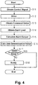
Fig. 4 is a flowchart showing steps of a process of determining the state of a transmission mechanism of the door device according to the first embodiment; and -
Fig. 5 is a block diagram schematically showing the configuration of a door device according to a third embodiment of the present invention. - The first embodiment of the present invention will now be described with reference to
Figs. 1 to 4 . - As shown in
Figs. 1 and2 , adoor device 10 is provided in, for example, a railroad vehicle and includes adoor 11, adrive unit 12 that drives thedoor 11, and atransmission mechanism 13 that transmits a driving force of thedrive unit 12 to thedoor 11. Thedoor 11 is moved to be opened or closed by the driving force of thedrive unit 12. Thedrive unit 12 is an electric motor. - The
drive unit 12 reciprocates apiston 12A in an axial direction. Thepiston 12A extends in a width direction of thedoor 11. Thepiston 12A corresponds to an output portion of thedrive unit 12. Afirst coupling member 13A is fixed to an end of thepiston 12A, thefirst coupling member 13A is coupled to thepiston 12A and extends in the vertical direction. Asecond coupling member 13B extending in the width direction of thedoor 11 is fixed to thefirst coupling member 13A. Athird coupling member 13C is fixed to thesecond coupling member 13B and to an upper end of thedoor 11. That is, thetransmission mechanism 13 includes thepiston 12A, thefirst coupling member 13A, thesecond coupling member 13B, and thethird coupling member 13C. The element disposed between thedrive unit 12 and thedoor 11 corresponds to thetransmission mechanism 13. Thefirst coupling member 13A, thesecond coupling member 13B, and thethird coupling member 13C constitute a bracket connecting thepiston 12A and thedoor 11. - As shown in
Fig. 3 , thedoor device 10 includes adoor control device 20, which controls thedrive unit 12. Thedoor control device 20 opens and closes thedoor 11 in response to open and close signals respectively, which are control signals output from ageneral control panel 1 provided in a driver's cab. Thedoor control device 20 may be formed of a processor equipped with, for example, a CPU, a RAM, and a ROM, and performs various processes in accordance with a computer program stored on a computer-readable medium, such as a ROM. One such computer program is a state determination program that determines the state of thetransmission mechanism 13 of thedoor device 10. Thedoor control device 20 determines the state of thetransmission mechanism 13 of thedoor device 10 according to a state determination program stored in a computer-readable medium. In other words, thedoor control device 20 is a state determination device that determines the state of thetransmission mechanism 13 of thedoor device 10. - The
door control device 20 includes acontrol unit 26 that controls thedrive unit 12. Thecontrol unit 26 opens and closes thedoor 11 by outputting a command value for driving thedrive unit 12 in a drive direction corresponding to the open signal or the close signal. Thecontrol unit 26 supplies, to thedrive unit 12, electric power according to a command value relating to the driving force. The driving force output from thedrive unit 12 is transmitted to thedoor 11 via thetransmission mechanism 13. - The
door control device 20 includes afirst acquisition unit 21 for obtaining a command value as driving force information regarding the driving force of thedrive unit 12 when thedoor 11 is driven, and asecond acquisition unit 22 for obtaining a load on thetransmission mechanism 13 that transmits the driving force of thedrive unit 12 to thedoor 11. Thefirst acquisition unit 21 obtains, from thecontrol unit 26, the command value related to the driving force. Thesecond acquisition unit 22 obtains the loads detected by afirst detection unit 31, asecond detection unit 32, athird detection unit 33, afourth detection unit 34, and afifth detection unit 35. The first tofifth detection units 31 to 35 each include, for example, a strain gauge to detect the load from the strain generated by transmission of the driving force, and output the load to thedoor control device 20 by wire or wirelessly. - As shown in
Figs. 1 and2 , thefirst detection unit 31 is attached near the tip end of thepiston 12A of thedrive unit 12. Thesecond detection unit 32 is attached to thefirst coupling member 13A of thetransmission mechanism 13. Thethird detection unit 33 is attached to thesecond coupling member 13B of thetransmission mechanism 13. Thefourth detection unit 34 is attached to thethird coupling member 13C of thetransmission mechanism 13. Thefifth detection unit 35 is attached to a lower side surface of thedoor 11. Thefifth detection unit 35 is able to detect a load at the position farthest from the output of thedrive unit 12. - As shown in
Fig. 3 , thedoor control device 20 includes adetermination unit 24 that determines the state of thetransmission mechanism 13 based on the command value obtained by thefirst acquisition unit 21 and the load obtained by thesecond acquisition unit 22. Thedoor control device 20 includes acalculation unit 23 that calculates, from the command value obtained by thefirst acquisition unit 21 and the load obtained by thesecond acquisition unit 22, a determination value used by thedetermination unit 24 for determination. Thedoor control device 20 includes astorage unit 25 storing the determination value calculated by thecalculation unit 23. - Here, loads detected by the first to
fifth detection units 31 to 35 differ depending on the coupling state between the corresponding member to be detected and the other members, the characteristics of the corresponding member, and the like. Thus, outputs are calculated from the loads detected by the first tofifth detection units 31 to 35 considering the characteristics of each member, and the state of thetransmission mechanism 13 is determined based on the calculated outputs. - The
determination unit 24 determines the state of thetransmission mechanism 13 based on the difference between the load based on the command value of the driving force obtained by thefirst acquisition unit 21 and the load on the transmission path of the driving force that are obtained by the second acquisition unit 22 (hereunder referred to as a determination method A). Specifically, thedetermination unit 24 determines the state of thetransmission mechanism 13 based on a determination value V1 which is hereunder described in detail. Thecalculation unit 23 calculates the determination value V1 that is used by thedetermination unit 24 for determination. Thedetermination unit 24 determines that the state of thetransmission mechanism 13 is normal when the determination value V1 calculated by thecalculation unit 23 falls within a predetermined range. When the determination value V1 is out of the predetermined range, thedetermination unit 24 determines that there is deterioration in thetransmission mechanism 13. The deterioration determined by thedetermination unit 24 refers to a state shortly before occurrence of a failure that thedoor 11 is unable to be moved. - The determination value V1 is defined as a difference between output calculated from the command value of the driving force and output calculated from a load detected by at least one of the first to
fifth detection units 31 to 35 provided in the transmission path of the driving force. - The
door device 10 includes anotification unit 27 that notifies a result of determination performed by thedetermination unit 24. Examples of thenotification unit 27 include a speaker producing sound, a lamp emitting light, and a display device displaying letters and/or images, and one or more may be selected from among these for a user. - Steps of operation of the
door control device 20 configured as described above will be now described with reference toFigs. 1 to 4 . - As shown in
Fig. 4 , thedoor control device 20 obtains the control signal (step S11). Specifically, in response to the open signal or close signal supplied as the control signal from thegeneral control panel 1, thedoor control device 20 starts a process to drive thedoor 11. - The
door control device 20 drives the drive unit 12 (step S12). Specifically, thecontrol unit 26 outputs an electric power corresponding to the command value for driving thedrive unit 12 in the drive direction corresponding to the open signal or the close signal. Thedrive unit 12 is driven based on the command value and outputs a driving force through thepiston 12A. The driving force is transmitted to thepiston 12A, thefirst coupling member 13A, thesecond coupling member 13B, thethird coupling member 13C, and thedoor 11 in this stated order. The driving force is transmitted and eventually moves the correspondingdoor 11. Since the effect of lateral pressure applied to thedoor 11 may be reduced, the state determination of thetransmission mechanism 13 is preferably performed when thedoor 11 is closed. - The
door control device 20 obtains the command value from the control unit 26 (step S13). Specifically, thefirst acquisition unit 21 obtains the command value output from thecontrol unit 26 when thecontrol unit 26 drives thedrive unit 12. Step S13 corresponds to the claimed first acquisition step. - The
door control device 20 obtains a load detected by each detection unit (step S14). Specifically, thesecond acquisition unit 22 obtains loads detected by thefirst detection unit 31, thesecond detection unit 32, thethird detection unit 33, thefourth detection unit 34, and thefifth detection unit 35. Alternatively, thesecond acquisition unit 22 may obtain only load(s) necessary for determination. Step S14 corresponds to the claimed second acquisition step. - The
door control device 20 calculates each output (step S15). Specifically, thecalculation unit 23 calculates output based on the loads obtained by thesecond acquisition unit 22. Further, thecalculation unit 23 calculates output based on the command value obtained by thefirst acquisition unit 21. Thestorage unit 25 stores the output that have been calculated by thecalculation unit 23 from the loads and the command value. - The
door control device 20 calculates a determination value (step S16). Specifically, thecalculation unit 23 calculates the determination value V1 by obtaining the difference between the output calculated from the command value of the driving force and the output calculated from the loads on the transmission path of the driving force. - The
door control device 20 determines whether the determination value falls within a predetermined range (step S17). If the determination value is large, there is a high possibility of deterioration in the transmission performance of thetransmission mechanism 13. Accordingly, thedetermination unit 24 determines that thetransmission mechanism 13 is normal when the determination value is within the predetermined range, and determines that thetransmission mechanism 13 is deteriorated when the determination value is out of the predetermined range. Note that step S17 corresponds to the claimed determination step. - When the determination value is within the predetermined range (step S17: YES), the
door control device 20 determines that the state of thetransmission mechanism 13 is normal, and thus ends the process. - Whereas when the determination value is out of the predetermined range (step S17: NO), the
door control device 20 determines that thetransmission mechanism 13 has deteriorated, and informs the deterioration (step S18). Specifically, thenotification unit 27 informs the deterioration by sound, light, or display. - As described above, the state of the
transmission mechanism 13 can be determined by detecting loads on thetransmission mechanism 13 of thedoor device 10, calculating the determination value, and determine whether the determination value is within a predetermined range. In this way, it is possible to detect deterioration before thedoor 11 actually fails and becomes unable to be moved. - Advantageous effects of the first embodiment will be now described.
- (1) By obtaining the command value and the load(s) on the
transmission mechanism 13, it is possible to determine the state of thetransmission mechanism 13 based on the obtained command value and the obtained load(s) on thetransmission mechanism 13. - (2) Since the
detection units coupling members transmission mechanism 13 that provides the transmission path of the driving force, it is possible to determine whether deterioration has occurred at any point of the transmission path. - (3) Although lateral pressure may be applied to the
door 11 when thedoor 11 is opened, the determination can be performed without the effect of the lateral pressure by performing the determination when thedoor 11 is closed. - The second embodiment of the present invention will be hereinafter described. In the second embodiment, the method of determining the state of the
transmission mechanism 13 of thedoor device 10 is different from that of the first embodiment. The following description will be focused on the difference from the first embodiment. - The
determination unit 24 determines the state of thetransmission mechanism 13 based on the difference between an upstream load and a downstream load on the driving force transmission path that are obtained by the second acquisition unit 22 (hereunder referred to as a determination method B). Specifically, thedetermination unit 24 determines the state of thetransmission mechanism 13 based on at least one of determination values V2 to V4, which are hereunder described in detail. Thecalculation unit 23 calculates the determination values V2 to V4 used by thedetermination unit 24 for determination. Thedetermination unit 24 determines that the state of thetransmission mechanism 13 is normal when the determination values V2 to V4 calculated by thecalculation unit 23 fall within a predetermined range. When the determination values V2 to V4 are out of the predetermined range, thedetermination unit 24 determines that there is deterioration in thetransmission mechanism 13. The deterioration determined by thedetermination unit 24 refers to a state shortly before occurrence of a failure that thedoor 11 is unable to be moved. - The determination value V2 is defined as a difference between output calculated from a load detected by the
first detection unit 31, which is situated upstream of the driving force transmission path, and output calculated from a load detected by at least one of the second tofifth detection units 32 to 35, which are situated downstream of the driving force transmission path. The load detected by thefirst detection unit 31 corresponds to the claimed load at a portion where directly receives the driving force of the drive unit, and the load detected by at least one of the second tofifth detection units 32 to 35 corresponds to the claimed load at a portion of the transmission path of the driving force other than the portion where directly receives the driving force. - The determination value V3 is defined as a difference between output calculated from a load detected by the
second detection unit 32, which is situated upstream of the driving force transmission path, and output calculated from a load detected by at least one of the third tofifth detection units 33 to 35, which are situated downstream of the driving force transmission path. - The determination value V4 is defined as a difference between output calculated from a load detected by the
third detection unit 33, which is situated upstream of the driving force transmission path, and output calculated from a load detected by at least one of the fourth andfifth detection units - Alternatively, the
determination unit 24 determines the state of thetransmission mechanism 13 based on a change in load on the driving force transmission path obtained at the same location by the second acquisition unit 22 (hereunder referred to as a determination method C). Specifically, thedetermination unit 24 determines the state of thetransmission mechanism 13 based on a determination value V5, which is hereunder described in detail. Thecalculation unit 23 calculates the determination value V5 used by thedetermination unit 24 for determination. Thedetermination unit 24 determines that the state of thetransmission mechanism 13 is normal when the determination value V5 calculated by thecalculation unit 23 falls within a predetermined range. When the determination value V5 is out of the predetermined range, thedetermination unit 24 determines that there is deterioration in thetransmission mechanism 13. The deterioration determined by thedetermination unit 24 refers to a state shortly before occurrence of a failure that thedoor 11 is unable to be moved. - The determination value V5 is defined as a difference between output calculated from a load that has been previously detected by one of the first to
fifth detection units 31 to 35 and output calculated from a load that is currently detected by the detection unit. The output calculated from the previous load is stored in thestorage unit 25. - Alternatively, the
determination unit 24 determines the state of thetransmission mechanism 13 based on loads on the driving force transmission path obtained at the same location by thesecond acquisition unit 22 under the same conditions (hereunder referred to as a determination method D). Specifically, thedetermination unit 24 determines the state of thetransmission mechanism 13 based on a determination value V6, which is hereunder described in detail. Thecalculation unit 23 calculates the determination value V6 used by thedetermination unit 24 for determination. Thedetermination unit 24 determines that the state of thetransmission mechanism 13 is normal when the determination value V6 calculated by thecalculation unit 23 falls within a predetermined range. When the determination value V6 is out of the predetermined range, thedetermination unit 24 determines that there is deterioration in thetransmission mechanism 13. The deterioration determined by thedetermination unit 24 refers to a state shortly before occurrence of a failure that thedoor 11 is unable to be moved. - The same condition stated above specifically means that no lateral pressure is applied to the
door 11, in other words, no passengers are on the railway vehicle T, and the temperature is the same. Thedetermination unit 24 determines whether any passengers are on board, that is, whether no lateral pressure is applied to thedoor 11 by obtaining information on a load applied to an air spring from thegeneral control panel 1. Further, thedetermination unit 24 determines whether or not the temperature is the same by obtaining the temperature information from thegeneral control panel 1 or a temperature sensor attached to the railway vehicle T. - The determination value V6 is defined as a difference between output calculated from a load that is currently detected by one of the first to
fifth detection units 31 to 35 and output calculated from a load that has been previously detected by the detection unit under the same conditions as the current load. The output calculated from the previous load is stored in thestorage unit 25. - Steps of operation of the
door control device 20 configured as described above will be now described. - As shown in
Fig. 4 , steps S11 to S15 and steps S17 to S18 are performed in the same manner as in the first embodiment. In step S16, the calculation of a determination value by thedoor control device 20 is performed by thecalculation unit 23 obtaining the differences among outputs calculated from loads on the driving force transmission path. - Specifically, in the determination method B, the
calculation unit 23 calculates at least one of the determination values V2 to V4 by respectively obtaining the difference between output calculated from an upstream load and output calculated from a downstream load in the driving force transmission path. In the determination method C, thecalculation unit 23 calculates the determination value V5 by obtaining the difference between output calculated from a previous load and output calculated from a current load at the same location. In the determination method D, thecalculation unit 23 calculates the determination value V6 by obtaining the difference between output calculated from a previous load and output calculated from a current load at the same location under the same conditions. - As described above, the state of the
transmission mechanism 13 can be determined by detecting loads on thetransmission mechanism 13 of thedoor device 10, calculating the determination value, and determine whether the determination value is within a predetermined range. In this way, it is possible to detect deterioration before thedoor 11 actually fails and becomes unable to be moved. - Advantageous effects of the second embodiment will be now described. The following advantageous effects can be obtained in addition to the advantageous effects (2) and (3) of the first embodiment.
- (4) By obtaining the difference between the upstream load and the downstream load in the driving force transmission path, it is possible to determine whether the transmission path of the
transmission mechanism 13 is deteriorated. Further, by narrowing the distance between the upstream load detection position and the downstream load detection position, it is possible to identify a deteriorated portion. - (5) By obtaining the difference between the load based on the input of the driving force and the load on the driving force transmission path, it is possible to determine whether the transmission path of the
transmission mechanism 13 is deteriorated. Further, since the input can be used as a reference, the determination can be made according to the change in load generated by the input. - (6) It is possible to determine whether there is deterioration of the transmission path of the
transmission mechanism 13 in consideration of change in load at the same location, that is, the change over time. By obtaining the change in load at the same location, it is possible to determine whether there is deterioration at that location. - (7) It is possible to determine whether there is deterioration of the transmission path of the
transmission mechanism 13 by obtaining a change in load at the same location under the same conditions, that is, the change overtime and the load under the same conditions. - The third embodiment of the present invention will now be described with reference to
Fig. 5 . The third embodiment is different from the first embodiment in that the state determination device is provided separately from the door control device. The following description will be focused on the difference from the first embodiment. - As shown in
Fig. 5 , adoor device 100 includes adoor control device 40, which controls thedrive unit 12, and astate determination device 50 that determines the state of thetransmission mechanism 13 of thedoor device 100. Thedoor control device 40 opens and closes thedoor 11 in response to open and close signals respectively, which are control signals output from ageneral control panel 1 provided in a driver's cab. - The
door control device 40 includes acontrol unit 41 that controls thedrive unit 12. Similar to thecontrol unit 26 of the first embodiment, thecontrol unit 41 opens and closes thedoor 11 by outputting a drive signal for driving thedrive unit 12 in a drive direction corresponding to the open signal or the close signal. The driving force output from thedrive unit 12 is transmitted to thedoor 11 via thetransmission mechanism 13. - The
state determination device 50 includes afirst acquisition unit 51 for obtaining a command value as driving force information regarding the driving force of thedrive unit 12 when thedoor 11 is driven, and asecond acquisition unit 52 for obtaining a load on thetransmission mechanism 13 that transmits the driving force of thedrive unit 12 to thedoor 11. Thefirst acquisition unit 51 obtains, from thecontrol unit 41, the command value related to the driving force. Similar to thesecond acquisition unit 22 of the first embodiment, thesecond acquisition unit 52 obtains loads detected by thefirst detection unit 31, thesecond detection unit 32, thethird detection unit 33, thefourth detection unit 34, and thefifth detection unit 35. - The
state determination device 50 includes adetermination unit 54 similar to thedetermination unit 24 of the first embodiment, which determines the state of thetransmission mechanism 13 based on the load obtained by thesecond acquisition unit 52. Thestate determination device 50 further includes acalculation unit 53 similar to thecalculation unit 23 of the first embodiment, which calculates, from the load obtained by thesecond acquisition unit 52, a determination value used by thedetermination unit 54 for determination. Thestate determination device 50 includes astorage unit 55 similar to thestorage unit 25 of the first embodiment, which stores the determination value calculated by thecalculation unit 53. Thedoor device 100 includes anotification unit 56 similar to thenotification unit 27 of the first embodiment, which notifies a result of determination performed by thedetermination unit 54. - As described above, even when the
state determination device 50 is provided separately from thedoor control device 40, thestate determination device 50 is able to determine the state of thetransmission mechanism 13. - According to the third embodiment, the advantageous effects (1) to (7) of the first and second embodiments are obtained.
- The foregoing embodiments may be modified as described below. The above embodiments and the following modifications may be combined with each other to such an extent that they are technically consistent with each other.
- In each of the above embodiments, the state of the
transmission mechanism 13 is determined when thedoor 11 is closed. However, the state of thetransmission mechanism 13 may be determined not only when thedoor 11 is closed but also when thedoor 11 is opened. - In each of the above embodiments, the state of the
transmission mechanism 13 may be determined by a method combining the determination methods A to D. - In each of the above embodiments, the loads are detected by the first to
fifth detection units 31 to 35. Alternatively, in the determination method A, the state of thetransmission mechanism 13 may be determined based on at least two detection results obtained from two of the first tofifth detection units 31 to 35. Alternatively, in the determination method B, the state of thetransmission mechanism 13 may be determined based on the detection result obtained from thefirst detection unit 31 and at least one detection result obtained from one of the second tofifth detection units 32 to 35. Alternatively, in the determination method C or D, the state of thetransmission mechanism 13 may be determined based on at least one detection result obtained from one of the first tofifth detection units 31 to 35. - In each of the above embodiments, the state of the
drive unit 12 may be determined based on the results of detection performed by thefirst detection unit 31. For example, the state of thedrive unit 12 can be determined by comparing the control of thecontrol unit - In each of the above embodiments, the state of the
door 11 may be determined based on the results of detection performed by thefifth detection unit 35. For example, the state of thedoor 11 can be determined by comparing the control of thecontrol unit - In each of the above embodiments, the positions to attach the detection units and the number of the detection units may be adequately selected. Specifically, the number of the detection units and the positions to attach the detection units may be adequately selected according to the configuration and shape of the transmission mechanism.
- In the third embodiment, the result of the determination performed by the
state determination device 50 may be output to thedoor control device 40, thedoor control device 40 that has obtained the determination result may notify the determination result or output the determination result to thegeneral control panel 1. - In each of the above embodiments, the
door device first door device second acquisition unit determination unit transmission mechanism 13 of thefirst door device transmission mechanism 13 of thefirst door device second acquisition unit transmission mechanism 13 is determined by calculating output from the load to obtain a determination value by thecalculation unit transmission mechanism 13 can be determined by comparing the load on thetransmission mechanism 13 of thefirst door device - In each of the above embodiments, the
drive unit 12 is an electric motor. Alternatively, the drive unit driving thedoor 11 may be an air cylinder. In the case of an air cylinder, an input air pressure and an output air pressure are measured to calculate the driving force. Further, the control unit controls the supply and discharge of air pressure according to a command value for driving the air cylinder in the drive direction corresponding to the open signal or the close signal. - The determination process in each of the above embodiments may be performed when the railway vehicle is in a shed or before operation. In this way, the state of the transmission mechanism can be determined before the operation of the railway vehicle.
- The present invention also encompasses the following embodiments.
- Additional Embodiment 1 A door device (10; 100) that includes a door (11), a drive unit (12) driving the door (11), and a transmission mechanism (13) transmitting a driving force of the drive unit (12) to the door (11), the door device (10; 100) comprising:
- a first acquisition unit (21; 51) obtaining driving force information regarding a driving force of the drive unit (12);
- a second acquisition unit (22; 52) obtaining a load on the transmission mechanism (13); and
- a determination unit (24; 54) determining the state of the transmission mechanism (13) based on the driving force information obtained by the first acquisition unit (21; 51) and the load obtained by the second acquisition unit (22; 52).
- Additional Embodiment 2 The door device (10; 100) according to
additional embodiment 1, wherein the determination unit (24; 54) determines the state of the transmission mechanism (13) based on the difference between an upstream load and a downstream load on a transmission path of the driving force that are obtained by the second acquisition unit (22; 52). -
Additional Embodiment 3 The door device (10; 100) according toadditional embodiment 1, wherein the determination unit (24; 54) determines the state of the transmission mechanism based on the difference between a load at a portion where directly receives the driving force of the drive unit (12) and a load at a portion of the transmission path of the driving force other than the portion where directly receives the driving force. - Additional Embodiment 4 The door device (10; 100) according to
additional embodiment 1, wherein the determination unit (24; 54) determines the state of the transmission mechanism (13) based on a change in load obtained at a same location by the second acquisition unit (22; 52). - Additional Embodiment 5 The door device (10; 100) according to
additional embodiment 1, wherein the determination unit (24; 54) determines the state of the transmission mechanism (13) based on loads obtained at a same location by the second acquisition unit (22; 52) under same conditions. - Additional Embodiment 6 The door device (10; 100) according to any one of
additional embodiments 1 to 5, wherein a detection unit (31, 32, 33, 34, 35) detecting the load is provided on each of an output portion (12A) of the drive unit (12), a bracket (13A, 13B, 13C) connecting the output portion (12A) and the door (11), and the door (11). - Additional Embodiment 7 The door device (10; 100) according to any one of
additional embodiments 1 to 6, wherein the determination unit (24; 54) determines the state of the transmission mechanism (13) when the door (11) is closed. - Additional Embodiment 8 The door device (10; 100) according to
additional embodiment 1, wherein
the door (11) is a first door (11) that is one of a plurality of doors provided in a same vehicle,
the second acquisition unit (22; 52) also obtains a load on a transmission mechanism that transmits a driving force to a second door that is another one of the plurality of doors, and
the determination unit (24; 54) determines the state of the transmission mechanism (13) transmitting the driving force to the first door (11) based on the load on the transmission mechanism (13) transmitting the driving force to the first door (11) and the load on the transmission mechanism transmitting the driving force to the second door that are obtained by the second acquisition unit (22; 52). - Additional Embodiment 9 The door device (10; 100) according to any one of
additional embodiments 1 to 8, further comprising a control unit (26, 41) controlling the drive unit (12).
Claims (13)
- A state determination device (20; 50), comprising:a first acquisition unit (21; 51) obtaining driving force information regarding a driving force of a drive unit (12) that drives a door (11);a second acquisition unit (22; 52) obtaining a load on a transmission mechanism (13) that transmits the driving force of the drive unit (12) to the door (11); anda determination unit (24; 54) determining the state of the transmission mechanism (13) based on the driving force information obtained by the first acquisition unit (21; 51) and the load obtained by the second acquisition unit (22; 52).
- The state determination device (20; 50) according to claim 1, wherein the determination unit (24; 54) determines the state of the transmission mechanism (13) based on the difference between an upstream load and a downstream load on a transmission path of the driving force that are obtained by the second acquisition unit (22; 52).
- The state determination device (20; 50) according to claim 1, wherein the determination unit (24; 54) determines the state of the transmission mechanism (13) based on the difference between a load at a portion where directly receives the driving force of the drive unit (12) and a load at a portion of the transmission path of the driving force other than the portion where directly receives the driving force.
- The state determination device (20; 50) according to claim 1, wherein the determination unit (24; 54) determines the state of the transmission mechanism (13) based on a change in load obtained at a same location by the second acquisition unit (22; 52).
- The state determination device (20; 50) according to claim 1, wherein the determination unit (24;54) determines the state of the transmission mechanism (13) based on loads obtained at a same location by the second acquisition unit (22; 52) under same conditions.
- The state determination device (20; 50) according to any one of claims 1 to 5, wherein a detection unit (31, 32, 33, 34, 35) detecting the load is provided on each of an output portion (12A) of the drive unit (12), a bracket (13A, 13B, 13C) connecting the output portion (12A) and the door (11), and the door (11).
- The state determination device (20; 50) according to any one of claims 1 to 6, wherein the determination unit (24; 54) determines the state of the transmission mechanism (13) when the door (11) is closed.
- The state determination device (20; 50) according to claim 1, wherein
the door (11) is a first door (11) that is one of a plurality of doors provided in a same vehicle,
the second acquisition unit (22; 52) also obtains a load on a transmission mechanism that transmits a driving force to a second door that is another one of the plurality of doors, and
the determination unit (24; 54) determines the state of the transmission mechanism (13) transmitting the driving force to the first door (11) based on the load on the transmission mechanism (13) transmitting the driving force to the first door (11) and the load on the transmission mechanism transmitting the driving force to the second door that are obtained by the second acquisition unit (22; 52). - The state determination device (20) according to any one of claims 1 to 8, further comprising a control unit (26) controlling the drive unit (12).
- A door control device (20), comprising:a first acquisition unit (21) obtaining driving force information regarding a driving force of a drive unit (12) that drives a door (11);a second acquisition unit (22) obtaining a load on a transmission mechanism (13) that transmits the driving force of the drive unit (12) to the door (11);a determination unit (24) determining the state of the transmission mechanism (13) based on the driving force information obtained by the first acquisition unit (21) and the load obtained by the second acquisition unit (22); anda control unit (26) controlling the drive unit (12).
- A state determination method, comprising
a first acquisition step of obtaining driving force information regarding a driving force of a drive unit (12) that drives a door (11)
a second acquisition step of obtaining a load on a transmission mechanism (13) that transmits the driving force of the drive unit (12) to the door (11); an
a determination step of determining the state of the transmission mechanism (13) based on the driving force information obtained in the first acquisition step and the load obtained in the second acquisition step. - A state determination program, causing a computer to perform
a first acquisition step of obtaining driving force information regarding a driving force of a drive unit (12) that drives a door (11)
a second acquisition step of obtaining a load on a transmission mechanism (13) that transmits the driving force of the drive unit (12) to the door (11); an
a determination step of determining the state of the transmission mechanism (13) based on the driving force information obtained in the first acquisition step and the load obtained in the second acquisition step. - A computer-readable medium storing the state determination program according to claim 12.
Applications Claiming Priority (1)
| Application Number | Priority Date | Filing Date | Title |
|---|---|---|---|
| JP2020036997A JP2021138264A (en) | 2020-03-04 | 2020-03-04 | State judgment device, door control device, state judgment method, and state judgment program |
Publications (2)
| Publication Number | Publication Date |
|---|---|
| EP3875936A1 true EP3875936A1 (en) | 2021-09-08 |
| EP3875936B1 EP3875936B1 (en) | 2023-05-10 |
Family
ID=74778931
Family Applications (1)
| Application Number | Title | Priority Date | Filing Date |
|---|---|---|---|
| EP21159615.0A Active EP3875936B1 (en) | 2020-03-04 | 2021-02-26 | State determination device, door control device, state determination method, and state determination program |
Country Status (3)
| Country | Link |
|---|---|
| EP (1) | EP3875936B1 (en) |
| JP (1) | JP2021138264A (en) |
| CN (1) | CN113353112A (en) |
Citations (5)
| Publication number | Priority date | Publication date | Assignee | Title |
|---|---|---|---|---|
| GB2409911A (en) * | 2004-01-06 | 2005-07-13 | Chamberlain Group Inc | Control of a moveable barrier |
| US20080179143A1 (en) * | 2005-09-05 | 2008-07-31 | Kone Corporation | Elevator arrangement |
| EP2565142A1 (en) * | 2010-04-30 | 2013-03-06 | Mitsubishi Electric Corporation | Door control device for elevator |
| US20160340149A1 (en) * | 2014-01-27 | 2016-11-24 | Siemens Aktiengesellschaft | Method for determining moving mass of a door system |
| JP2017149290A (en) | 2016-02-25 | 2017-08-31 | 川崎重工業株式会社 | Railway vehicle bearing monitoring device |
Family Cites Families (5)
| Publication number | Priority date | Publication date | Assignee | Title |
|---|---|---|---|---|
| FR2742474B3 (en) * | 1995-09-08 | 1997-12-19 | Geze Gmbh & Co | SLIDING DOOR PROVIDED WITH AN EMERGENCY OPENING OR CLOSING DEVICE |
| JP3415014B2 (en) * | 1997-12-26 | 2003-06-09 | アスモ株式会社 | Automatic switchgear |
| DE102017102614A1 (en) * | 2017-02-09 | 2018-08-09 | Efaflex Tor- Und Sicherheitssysteme Gmbh & Co. Kg | Door panel crash detection system, door panel crash detection system, and door panel crash detection method |
| DE102020205220A1 (en) * | 2020-04-24 | 2021-10-28 | Thyssenkrupp Elevator Innovation And Operations Ag | Method and system for maintenance of the door mechanism of an elevator installation |
| DE102020205217A1 (en) * | 2020-04-24 | 2021-10-28 | Thyssenkrupp Elevator Innovation And Operations Ag | Method and control system for maintaining the door mechanism of an elevator installation |
-
2020
- 2020-03-04 JP JP2020036997A patent/JP2021138264A/en active Pending
-
2021
- 2021-02-26 EP EP21159615.0A patent/EP3875936B1/en active Active
- 2021-03-02 CN CN202110230995.0A patent/CN113353112A/en active Pending
Patent Citations (5)
| Publication number | Priority date | Publication date | Assignee | Title |
|---|---|---|---|---|
| GB2409911A (en) * | 2004-01-06 | 2005-07-13 | Chamberlain Group Inc | Control of a moveable barrier |
| US20080179143A1 (en) * | 2005-09-05 | 2008-07-31 | Kone Corporation | Elevator arrangement |
| EP2565142A1 (en) * | 2010-04-30 | 2013-03-06 | Mitsubishi Electric Corporation | Door control device for elevator |
| US20160340149A1 (en) * | 2014-01-27 | 2016-11-24 | Siemens Aktiengesellschaft | Method for determining moving mass of a door system |
| JP2017149290A (en) | 2016-02-25 | 2017-08-31 | 川崎重工業株式会社 | Railway vehicle bearing monitoring device |
Also Published As
| Publication number | Publication date |
|---|---|
| JP2021138264A (en) | 2021-09-16 |
| CN113353112A (en) | 2021-09-07 |
| EP3875936B1 (en) | 2023-05-10 |
Similar Documents
| Publication | Publication Date | Title |
|---|---|---|
| US11365580B2 (en) | Method and adjusting device for adjusting a vehicle adjusting part with output status information | |
| KR102214332B1 (en) | System for making a driver operate a car easily method for determining abnormality vertical angle of radar sensor at system for making a driver operate a car easily | |
| US10889464B2 (en) | System for the generation of call advance data | |
| CN112477871A (en) | Identifying hand-off conditions based on group data | |
| EP3875936B1 (en) | State determination device, door control device, state determination method, and state determination program | |
| JP2009121144A (en) | Vehicle door safety confirmation system | |
| EP1588924A3 (en) | Vehicle controller | |
| KR20170106015A (en) | Tire pressure estimation apparatus and estimation method thereof | |
| JP5091638B2 (en) | Elevator car guide device | |
| EP3670297B1 (en) | Steering system monitoring | |
| CN104428231A (en) | Elevator device | |
| EP3647153A1 (en) | Train coupling support system | |
| US20210053446A1 (en) | Device and Method for Controlling a Current Collector for a Vehicle | |
| US9007385B2 (en) | Image processing apparatus | |
| JP4763782B2 (en) | Pedestrian collision identification device | |
| JP2008117140A (en) | Driver dependence determination device and program, and driving support device and program | |
| JPH10258976A (en) | Governor rope trouble detecting device for elevator | |
| KR101808971B1 (en) | Elevator system | |
| JP7834179B2 (en) | Impact detection system | |
| JP7691389B2 (en) | Fault sign diagnostic device and fault sign diagnostic method | |
| KR20130019940A (en) | Diagnostic device for suspension | |
| KR101746150B1 (en) | Apparatus and method for controlling tensioner determining specimen of TWB | |
| KR20170030299A (en) | Apparatus and method for detecting defect of TWB | |
| KR102549147B1 (en) | Surround Wanning System and Method for Vehicle | |
| KR101853781B1 (en) | Apparatus for controlling brake pedal and method for controlling thereof |
Legal Events
| Date | Code | Title | Description |
|---|---|---|---|
| PUAI | Public reference made under article 153(3) epc to a published international application that has entered the european phase |
Free format text: ORIGINAL CODE: 0009012 |
|
| STAA | Information on the status of an ep patent application or granted ep patent |
Free format text: STATUS: REQUEST FOR EXAMINATION WAS MADE |
|
| 17P | Request for examination filed |
Effective date: 20210226 |
|
| AK | Designated contracting states |
Kind code of ref document: A1 Designated state(s): AL AT BE BG CH CY CZ DE DK EE ES FI FR GB GR HR HU IE IS IT LI LT LU LV MC MK MT NL NO PL PT RO RS SE SI SK SM TR |
|
| STAA | Information on the status of an ep patent application or granted ep patent |
Free format text: STATUS: EXAMINATION IS IN PROGRESS |
|
| 17Q | First examination report despatched |
Effective date: 20220524 |
|
| GRAP | Despatch of communication of intention to grant a patent |
Free format text: ORIGINAL CODE: EPIDOSNIGR1 |
|
| STAA | Information on the status of an ep patent application or granted ep patent |
Free format text: STATUS: GRANT OF PATENT IS INTENDED |
|
| INTG | Intention to grant announced |
Effective date: 20221129 |
|
| GRAS | Grant fee paid |
Free format text: ORIGINAL CODE: EPIDOSNIGR3 |
|
| GRAA | (expected) grant |
Free format text: ORIGINAL CODE: 0009210 |
|
| STAA | Information on the status of an ep patent application or granted ep patent |
Free format text: STATUS: THE PATENT HAS BEEN GRANTED |
|
| AK | Designated contracting states |
Kind code of ref document: B1 Designated state(s): AL AT BE BG CH CY CZ DE DK EE ES FI FR GB GR HR HU IE IS IT LI LT LU LV MC MK MT NL NO PL PT RO RS SE SI SK SM TR |
|
| REG | Reference to a national code |
Ref country code: GB Ref legal event code: FG4D |
|
| REG | Reference to a national code |
Ref country code: AT Ref legal event code: REF Ref document number: 1567132 Country of ref document: AT Kind code of ref document: T Effective date: 20230515 Ref country code: CH Ref legal event code: EP |
|
| REG | Reference to a national code |
Ref country code: DE Ref legal event code: R096 Ref document number: 602021002230 Country of ref document: DE |
|
| REG | Reference to a national code |
Ref country code: IE Ref legal event code: FG4D |
|
| P01 | Opt-out of the competence of the unified patent court (upc) registered |
Effective date: 20230523 |
|
| REG | Reference to a national code |
Ref country code: LT Ref legal event code: MG9D |
|
| REG | Reference to a national code |
Ref country code: NL Ref legal event code: MP Effective date: 20230510 |
|
| REG | Reference to a national code |
Ref country code: AT Ref legal event code: MK05 Ref document number: 1567132 Country of ref document: AT Kind code of ref document: T Effective date: 20230510 |
|
| PG25 | Lapsed in a contracting state [announced via postgrant information from national office to epo] |
Ref country code: SE Free format text: LAPSE BECAUSE OF FAILURE TO SUBMIT A TRANSLATION OF THE DESCRIPTION OR TO PAY THE FEE WITHIN THE PRESCRIBED TIME-LIMIT Effective date: 20230510 Ref country code: PT Free format text: LAPSE BECAUSE OF FAILURE TO SUBMIT A TRANSLATION OF THE DESCRIPTION OR TO PAY THE FEE WITHIN THE PRESCRIBED TIME-LIMIT Effective date: 20230911 Ref country code: NO Free format text: LAPSE BECAUSE OF FAILURE TO SUBMIT A TRANSLATION OF THE DESCRIPTION OR TO PAY THE FEE WITHIN THE PRESCRIBED TIME-LIMIT Effective date: 20230810 Ref country code: NL Free format text: LAPSE BECAUSE OF FAILURE TO SUBMIT A TRANSLATION OF THE DESCRIPTION OR TO PAY THE FEE WITHIN THE PRESCRIBED TIME-LIMIT Effective date: 20230510 Ref country code: ES Free format text: LAPSE BECAUSE OF FAILURE TO SUBMIT A TRANSLATION OF THE DESCRIPTION OR TO PAY THE FEE WITHIN THE PRESCRIBED TIME-LIMIT Effective date: 20230510 Ref country code: AT Free format text: LAPSE BECAUSE OF FAILURE TO SUBMIT A TRANSLATION OF THE DESCRIPTION OR TO PAY THE FEE WITHIN THE PRESCRIBED TIME-LIMIT Effective date: 20230510 |
|
| PG25 | Lapsed in a contracting state [announced via postgrant information from national office to epo] |
Ref country code: RS Free format text: LAPSE BECAUSE OF FAILURE TO SUBMIT A TRANSLATION OF THE DESCRIPTION OR TO PAY THE FEE WITHIN THE PRESCRIBED TIME-LIMIT Effective date: 20230510 Ref country code: PL Free format text: LAPSE BECAUSE OF FAILURE TO SUBMIT A TRANSLATION OF THE DESCRIPTION OR TO PAY THE FEE WITHIN THE PRESCRIBED TIME-LIMIT Effective date: 20230510 Ref country code: LV Free format text: LAPSE BECAUSE OF FAILURE TO SUBMIT A TRANSLATION OF THE DESCRIPTION OR TO PAY THE FEE WITHIN THE PRESCRIBED TIME-LIMIT Effective date: 20230510 Ref country code: LT Free format text: LAPSE BECAUSE OF FAILURE TO SUBMIT A TRANSLATION OF THE DESCRIPTION OR TO PAY THE FEE WITHIN THE PRESCRIBED TIME-LIMIT Effective date: 20230510 Ref country code: IS Free format text: LAPSE BECAUSE OF FAILURE TO SUBMIT A TRANSLATION OF THE DESCRIPTION OR TO PAY THE FEE WITHIN THE PRESCRIBED TIME-LIMIT Effective date: 20230910 Ref country code: HR Free format text: LAPSE BECAUSE OF FAILURE TO SUBMIT A TRANSLATION OF THE DESCRIPTION OR TO PAY THE FEE WITHIN THE PRESCRIBED TIME-LIMIT Effective date: 20230510 Ref country code: GR Free format text: LAPSE BECAUSE OF FAILURE TO SUBMIT A TRANSLATION OF THE DESCRIPTION OR TO PAY THE FEE WITHIN THE PRESCRIBED TIME-LIMIT Effective date: 20230811 |
|
| PG25 | Lapsed in a contracting state [announced via postgrant information from national office to epo] |
Ref country code: FI Free format text: LAPSE BECAUSE OF FAILURE TO SUBMIT A TRANSLATION OF THE DESCRIPTION OR TO PAY THE FEE WITHIN THE PRESCRIBED TIME-LIMIT Effective date: 20230510 |
|
| PG25 | Lapsed in a contracting state [announced via postgrant information from national office to epo] |
Ref country code: SK Free format text: LAPSE BECAUSE OF FAILURE TO SUBMIT A TRANSLATION OF THE DESCRIPTION OR TO PAY THE FEE WITHIN THE PRESCRIBED TIME-LIMIT Effective date: 20230510 |
|
| PG25 | Lapsed in a contracting state [announced via postgrant information from national office to epo] |
Ref country code: SM Free format text: LAPSE BECAUSE OF FAILURE TO SUBMIT A TRANSLATION OF THE DESCRIPTION OR TO PAY THE FEE WITHIN THE PRESCRIBED TIME-LIMIT Effective date: 20230510 Ref country code: SK Free format text: LAPSE BECAUSE OF FAILURE TO SUBMIT A TRANSLATION OF THE DESCRIPTION OR TO PAY THE FEE WITHIN THE PRESCRIBED TIME-LIMIT Effective date: 20230510 Ref country code: RO Free format text: LAPSE BECAUSE OF FAILURE TO SUBMIT A TRANSLATION OF THE DESCRIPTION OR TO PAY THE FEE WITHIN THE PRESCRIBED TIME-LIMIT Effective date: 20230510 Ref country code: EE Free format text: LAPSE BECAUSE OF FAILURE TO SUBMIT A TRANSLATION OF THE DESCRIPTION OR TO PAY THE FEE WITHIN THE PRESCRIBED TIME-LIMIT Effective date: 20230510 Ref country code: DK Free format text: LAPSE BECAUSE OF FAILURE TO SUBMIT A TRANSLATION OF THE DESCRIPTION OR TO PAY THE FEE WITHIN THE PRESCRIBED TIME-LIMIT Effective date: 20230510 Ref country code: CZ Free format text: LAPSE BECAUSE OF FAILURE TO SUBMIT A TRANSLATION OF THE DESCRIPTION OR TO PAY THE FEE WITHIN THE PRESCRIBED TIME-LIMIT Effective date: 20230510 |
|
| REG | Reference to a national code |
Ref country code: DE Ref legal event code: R097 Ref document number: 602021002230 Country of ref document: DE |
|
| PLBE | No opposition filed within time limit |
Free format text: ORIGINAL CODE: 0009261 |
|
| STAA | Information on the status of an ep patent application or granted ep patent |
Free format text: STATUS: NO OPPOSITION FILED WITHIN TIME LIMIT |
|
| 26N | No opposition filed |
Effective date: 20240213 |
|
| PGFP | Annual fee paid to national office [announced via postgrant information from national office to epo] |
Ref country code: DE Payment date: 20240219 Year of fee payment: 4 |
|
| PG25 | Lapsed in a contracting state [announced via postgrant information from national office to epo] |
Ref country code: SI Free format text: LAPSE BECAUSE OF FAILURE TO SUBMIT A TRANSLATION OF THE DESCRIPTION OR TO PAY THE FEE WITHIN THE PRESCRIBED TIME-LIMIT Effective date: 20230510 |
|
| PG25 | Lapsed in a contracting state [announced via postgrant information from national office to epo] |
Ref country code: SI Free format text: LAPSE BECAUSE OF FAILURE TO SUBMIT A TRANSLATION OF THE DESCRIPTION OR TO PAY THE FEE WITHIN THE PRESCRIBED TIME-LIMIT Effective date: 20230510 Ref country code: IT Free format text: LAPSE BECAUSE OF FAILURE TO SUBMIT A TRANSLATION OF THE DESCRIPTION OR TO PAY THE FEE WITHIN THE PRESCRIBED TIME-LIMIT Effective date: 20230510 |
|
| PGFP | Annual fee paid to national office [announced via postgrant information from national office to epo] |
Ref country code: FR Payment date: 20240222 Year of fee payment: 4 |
|
| PG25 | Lapsed in a contracting state [announced via postgrant information from national office to epo] |
Ref country code: MC Free format text: LAPSE BECAUSE OF FAILURE TO SUBMIT A TRANSLATION OF THE DESCRIPTION OR TO PAY THE FEE WITHIN THE PRESCRIBED TIME-LIMIT Effective date: 20230510 |
|
| REG | Reference to a national code |
Ref country code: CH Ref legal event code: PL |
|
| PG25 | Lapsed in a contracting state [announced via postgrant information from national office to epo] |
Ref country code: LU Free format text: LAPSE BECAUSE OF NON-PAYMENT OF DUE FEES Effective date: 20240226 |
|
| PG25 | Lapsed in a contracting state [announced via postgrant information from national office to epo] |
Ref country code: CH Free format text: LAPSE BECAUSE OF NON-PAYMENT OF DUE FEES Effective date: 20240229 |
|
| PG25 | Lapsed in a contracting state [announced via postgrant information from national office to epo] |
Ref country code: LU Free format text: LAPSE BECAUSE OF NON-PAYMENT OF DUE FEES Effective date: 20240226 Ref country code: CH Free format text: LAPSE BECAUSE OF NON-PAYMENT OF DUE FEES Effective date: 20240229 |
|
| PG25 | Lapsed in a contracting state [announced via postgrant information from national office to epo] |
Ref country code: BG Free format text: LAPSE BECAUSE OF FAILURE TO SUBMIT A TRANSLATION OF THE DESCRIPTION OR TO PAY THE FEE WITHIN THE PRESCRIBED TIME-LIMIT Effective date: 20230510 |
|
| PG25 | Lapsed in a contracting state [announced via postgrant information from national office to epo] |
Ref country code: BG Free format text: LAPSE BECAUSE OF FAILURE TO SUBMIT A TRANSLATION OF THE DESCRIPTION OR TO PAY THE FEE WITHIN THE PRESCRIBED TIME-LIMIT Effective date: 20230510 |
|
| REG | Reference to a national code |
Ref country code: BE Ref legal event code: MM Effective date: 20240229 |
|
| PG25 | Lapsed in a contracting state [announced via postgrant information from national office to epo] |
Ref country code: BE Free format text: LAPSE BECAUSE OF NON-PAYMENT OF DUE FEES Effective date: 20240229 |
|
| PG25 | Lapsed in a contracting state [announced via postgrant information from national office to epo] |
Ref country code: IE Free format text: LAPSE BECAUSE OF NON-PAYMENT OF DUE FEES Effective date: 20240226 |
|
| PG25 | Lapsed in a contracting state [announced via postgrant information from national office to epo] |
Ref country code: IE Free format text: LAPSE BECAUSE OF NON-PAYMENT OF DUE FEES Effective date: 20240226 Ref country code: BE Free format text: LAPSE BECAUSE OF NON-PAYMENT OF DUE FEES Effective date: 20240229 |
|
| PG25 | Lapsed in a contracting state [announced via postgrant information from national office to epo] |
Ref country code: CY Free format text: LAPSE BECAUSE OF FAILURE TO SUBMIT A TRANSLATION OF THE DESCRIPTION OR TO PAY THE FEE WITHIN THE PRESCRIBED TIME-LIMIT; INVALID AB INITIO Effective date: 20210226 |
|
| REG | Reference to a national code |
Ref country code: DE Ref legal event code: R119 Ref document number: 602021002230 Country of ref document: DE |
|
| PG25 | Lapsed in a contracting state [announced via postgrant information from national office to epo] |
Ref country code: HU Free format text: LAPSE BECAUSE OF FAILURE TO SUBMIT A TRANSLATION OF THE DESCRIPTION OR TO PAY THE FEE WITHIN THE PRESCRIBED TIME-LIMIT; INVALID AB INITIO Effective date: 20210226 |
|
| GBPC | Gb: european patent ceased through non-payment of renewal fee |
Effective date: 20250226 |
|
| PG25 | Lapsed in a contracting state [announced via postgrant information from national office to epo] |
Ref country code: TR Free format text: LAPSE BECAUSE OF FAILURE TO SUBMIT A TRANSLATION OF THE DESCRIPTION OR TO PAY THE FEE WITHIN THE PRESCRIBED TIME-LIMIT Effective date: 20230510 |
|
| PG25 | Lapsed in a contracting state [announced via postgrant information from national office to epo] |
Ref country code: DE Free format text: LAPSE BECAUSE OF NON-PAYMENT OF DUE FEES Effective date: 20250902 |
|
| PG25 | Lapsed in a contracting state [announced via postgrant information from national office to epo] |
Ref country code: GB Free format text: LAPSE BECAUSE OF NON-PAYMENT OF DUE FEES Effective date: 20250226 |
|
| PG25 | Lapsed in a contracting state [announced via postgrant information from national office to epo] |
Ref country code: FR Free format text: LAPSE BECAUSE OF NON-PAYMENT OF DUE FEES Effective date: 20250228 |