EP3875935A1 - Method for setting bottom-touching-determination standard - Google Patents
Method for setting bottom-touching-determination standard Download PDFInfo
- Publication number
- EP3875935A1 EP3875935A1 EP19879680.7A EP19879680A EP3875935A1 EP 3875935 A1 EP3875935 A1 EP 3875935A1 EP 19879680 A EP19879680 A EP 19879680A EP 3875935 A1 EP3875935 A1 EP 3875935A1
- Authority
- EP
- European Patent Office
- Prior art keywords
- touching
- screw
- axial force
- determination
- measurement
- Prior art date
- Legal status (The legal status is an assumption and is not a legal conclusion. Google has not performed a legal analysis and makes no representation as to the accuracy of the status listed.)
- Granted
Links
Images

Classifications
-
- G—PHYSICS
- G01—MEASURING; TESTING
- G01L—MEASURING FORCE, STRESS, TORQUE, WORK, MECHANICAL POWER, MECHANICAL EFFICIENCY, OR FLUID PRESSURE
- G01L25/00—Testing or calibrating of apparatus for measuring force, torque, work, mechanical power, or mechanical efficiency
-
- B—PERFORMING OPERATIONS; TRANSPORTING
- B25—HAND TOOLS; PORTABLE POWER-DRIVEN TOOLS; MANIPULATORS
- B25B—TOOLS OR BENCH DEVICES NOT OTHERWISE PROVIDED FOR, FOR FASTENING, CONNECTING, DISENGAGING, OR HOLDING
- B25B23/00—Details of, or accessories for, spanners, wrenches, screwdrivers
-
- B—PERFORMING OPERATIONS; TRANSPORTING
- B23—MACHINE TOOLS; METAL-WORKING NOT OTHERWISE PROVIDED FOR
- B23P—METAL-WORKING NOT OTHERWISE PROVIDED FOR; COMBINED OPERATIONS; UNIVERSAL MACHINE TOOLS
- B23P19/00—Machines for simply fitting together or separating metal parts or objects, or metal and non-metal parts, whether or not involving some deformation; Tools or devices therefor so far as not provided for in other classes
- B23P19/04—Machines for simply fitting together or separating metal parts or objects, or metal and non-metal parts, whether or not involving some deformation; Tools or devices therefor so far as not provided for in other classes for assembling or disassembling parts
- B23P19/06—Screw or nut setting or loosening machines
- B23P19/065—Arrangements for torque limiters or torque indicators in screw or nut setting machines
- B23P19/066—Arrangements for torque limiters or torque indicators in screw or nut setting machines by electrical means
-
- B—PERFORMING OPERATIONS; TRANSPORTING
- B25—HAND TOOLS; PORTABLE POWER-DRIVEN TOOLS; MANIPULATORS
- B25B—TOOLS OR BENCH DEVICES NOT OTHERWISE PROVIDED FOR, FOR FASTENING, CONNECTING, DISENGAGING, OR HOLDING
- B25B23/00—Details of, or accessories for, spanners, wrenches, screwdrivers
- B25B23/14—Arrangement of torque limiters or torque indicators in wrenches or screwdrivers
-
- G—PHYSICS
- G01—MEASURING; TESTING
- G01L—MEASURING FORCE, STRESS, TORQUE, WORK, MECHANICAL POWER, MECHANICAL EFFICIENCY, OR FLUID PRESSURE
- G01L3/00—Measuring torque, work, mechanical power, or mechanical efficiency, in general
- G01L3/02—Rotary-transmission dynamometers
- G01L3/14—Rotary-transmission dynamometers wherein the torque-transmitting element is other than a torsionally-flexible shaft
- G01L3/1464—Rotary-transmission dynamometers wherein the torque-transmitting element is other than a torsionally-flexible shaft involving screws and nuts, screw-gears or cams
-
- G—PHYSICS
- G01—MEASURING; TESTING
- G01L—MEASURING FORCE, STRESS, TORQUE, WORK, MECHANICAL POWER, MECHANICAL EFFICIENCY, OR FLUID PRESSURE
- G01L5/00—Apparatus for, or methods of, measuring force, work, mechanical power, or torque, specially adapted for specific purposes
- G01L5/12—Apparatus for, or methods of, measuring force, work, mechanical power, or torque, specially adapted for specific purposes for measuring axial thrust in a rotary shaft, e.g. of propulsion plants
-
- G—PHYSICS
- G01—MEASURING; TESTING
- G01L—MEASURING FORCE, STRESS, TORQUE, WORK, MECHANICAL POWER, MECHANICAL EFFICIENCY, OR FLUID PRESSURE
- G01L5/00—Apparatus for, or methods of, measuring force, work, mechanical power, or torque, specially adapted for specific purposes
- G01L5/24—Apparatus for, or methods of, measuring force, work, mechanical power, or torque, specially adapted for specific purposes for determining value of torque or twisting moment for tightening a nut or other member which is similarly stressed
-
- G—PHYSICS
- G01—MEASURING; TESTING
- G01L—MEASURING FORCE, STRESS, TORQUE, WORK, MECHANICAL POWER, MECHANICAL EFFICIENCY, OR FLUID PRESSURE
- G01L5/00—Apparatus for, or methods of, measuring force, work, mechanical power, or torque, specially adapted for specific purposes
- G01L5/24—Apparatus for, or methods of, measuring force, work, mechanical power, or torque, specially adapted for specific purposes for determining value of torque or twisting moment for tightening a nut or other member which is similarly stressed
- G01L5/246—Apparatus for, or methods of, measuring force, work, mechanical power, or torque, specially adapted for specific purposes for determining value of torque or twisting moment for tightening a nut or other member which is similarly stressed using acoustic waves
Definitions
- the disclosure relates to a method for setting bottom-touching-determination standard used to determine a bottom-touching defect in screw tightening.
- bottom-touching occurs when screws are tightened by a screw tightening device, no axial force is generated, so that an appropriate fastening force cannot be obtained. If there is a gap between the bearing surface of the screw and the object to be fastened, it can be detected that bottom-touching has occurred, but sometimes bottom-touching occurs even when there is no gap between the bearing surface of the screw and the object to be fastened. Such bottom-touching can be detected by measuring the axial force of the screw.
- Patent literature 1 discloses a nut runner with an axial force meter.
- the nut runner with an axial force meter includes a probe having a vibration generator that vibrates the bolt head vertically by an electromagnetic force and a vibration detector that detects the vertical vibration, converts the vibration into a signal and outputs the signal.
- the nut runner with an axial force meter generates vibration in the bolt by the vibration generator, detects the vibration with the vibration detector, processes the detection signal with a control device to calculate the resonance frequency, and makes an association with the bolt axial force (bolt tightening force).
- Patent Literature 1 Japanese Patent Publication " Japanese Patent Laid-open No. 2004-291217 (published on October 21, 2004)"
- Patent literature 1 includes a probe for measuring the axial force
- bottom-touching can be detected according to parameters based on measured values obtained in a normal nut runner without an axial force meter.
- the vibration generator generates vibration in the bolt, the vibration is detected by the vibration detector, the detection signal is processed by the control device to calculate the resonance frequency, and an associating is made with the bolt axial force to thereby measure the axial force.
- the axial force is indirectly measured, the precision of the measurement result is low and there is a possibility of erroneous determination.
- One aspect of the disclosure aims to provide a method for setting bottom-touching-determination standard which is capable of setting a bottom-touching-determination standard based on parameters with high reliability.
- the method for setting bottom-touching-determination standard sets a standard for determining bottom-touching in screw tightening.
- a measuring system which includes a screw hole member having a measurement screw hole of a predetermined depth and an axial force measuring device that measures a compressive force applied between the screw hole member and a bearing surface of a measurement screw screwed into the measurement screw hole.
- the method includes: a screwing step of screwing the measurement screw into the measurement screw hole; a parameter acquisition step of acquiring parameters in the screwing step; an axial force measurement step of measuring the axial force of the measurement screw applied between the bearing surface and the screw hole member by the axial force measuring device; a bottom-touching-determination step of determining the presence or absence of bottom-touching on the basis of the axial force; and a determination standard setting step of setting a bottom-touching-determination standard based on the parameters by collating the determination result in the bottom-touching-determination step with the parameters acquired in the parameter acquisition step.
- the bottom-touching-determination standard based on parameters can be set with high reliability.
- FIG. 2 is a diagram showing an example of the state in which an object to be fastened 102 is fastened to a fastening object 103 by a fastening screw 101, in which (a) is a diagram showing the state in which the bearing surface is floating from the object to be fastened 102, and (b) is a diagram showing the state in which the bearing surface is in contact with the object to be fastened 102.
- the axial force in the state that the object to be fastened 102 is fastened to a screw hole member 13 by a measurement screw 11 is measured by a load cell 14 (axial force measuring device) arranged between the object to be fastened 102 and the screw hole member 13.
- the screw hole member 13 has a measurement screw hole 13a having a predetermined depth.
- the load cell 14 measures the compressive force applied between the bearing surface 11a of the measurement screw 11 screwed into the measurement screw hole 13a and the screw hole member 13.
- the compressive force applied between the bearing surface 11a of the measurement screw 11 and the screw hole member 13, that is, the axial force can be directly measured, so that highly precise measurement can be performed.
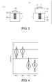
- FIG. 4 is a graph showing the results of measuring the axial force by the load cell 14 for four types of screws.
- the vertical axis indicates the axial force
- the horizontal width indicates the distribution (probability density) when the measurement is performed a plurality of times.
- the following axial forces are shown in order from the left.
- bottom-touching-determination standard In the method of setting bottom-touching-determination standard according to the present embodiment, an attempt is made to set the bottom-touching-determination standard based on parameters in screw tightening by collating the parameters with the presence or absence of bottom-touching determined on the basis of the axial force. Then, depending on whether or not the bottom-touching-determination standard can be set, it is determined whether or not the parameters are appropriate as the parameters for determining the presence or absence of bottom-touching.
- FIG. 1 is a diagram showing an example of a standard setting system 1 for executing the method for setting bottom-touching-determination standard according to the present embodiment.
- the standard setting system 1 includes the measurement screw 11, the object to be fastened 102, a measuring system 2, and a flanged washer 15.
- the standard setting system 1 further includes a standard setting device (not shown) for setting a standard for parameters, and a screw tightening device (not shown) for tightening the measurement screw 11.
- the measuring system 2 includes the screw hole member 13 and the load cell 14 described above.
- the flanged washer 15 is an annular member arranged above and below the load cell 14 while surrounding the measurement screw 11. Therefore, the load cell 14 abuts against the object to be fastened 102 via the flanged washer 15 arranged on the upper side, and abuts against the screw hole member 13 via the flanged washer 15 arranged on the lower side.
- the measurement screw 11 is longer than the fastening screw 101 by the thickness of the load cell 14 and the flanged washer 15.
- the length L at which the measurement screw 11 is screwed into the screw hole member 13 is equal to the length L at which the fastening screw 101 is screwed into the fastening object 103. Therefore, the parameters in the screw tightening process of the measurement screw 11 and the axial force at the completion of screw tightening are equal to the parameters in the screw tightening process of the fastening screw 101 and the axial force at the completion of screw tightening, respectively.
- the screw tightening device performs screw tightening in which the measurement screw 11 is screwed into the measurement screw hole 13a.
- the screw tightening device is controlled by the standard setting device.
- the standard setting device executes the method for setting bottom-touching-determination standard that sets a standard for determining bottom-touching in screw tightening.
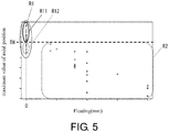
- FIG. 5 is a graph showing an example in which the bottom-touching-determination standard is set by the method for setting bottom-touching-determination standard according to the present embodiment.
- the maximum value of the position of the driver in the axial direction is used as a parameter for setting the standard.
- the horizontal axis shows the floating of the bearing surface of the measurement screw 11 from the object to be fastened 102
- the vertical axis shows the maximum value of the position of the driver in the axial direction in the screw tightening process.
- the floating of the bearing surface of the measurement screw 11 from the object to be fastened 102 may be simply referred to as "floating of the bearing surface".
- the region where the data points exist is divided into regions R1 and R2.
- the region R1 is divided into regions R11 and R12.
- the region R2 is a region including all data points whose bearing surface floating is larger than 0 mm. Bottom-touching occurred in all the screws with data points in the region R2.
- the region R1 is a region including all the data points where the floating of the bearing surface is 0 mm. Of the screws whose data points are included in the region R1, no bottom-touching occurred in the screws whose data points are included in the region R11. On the other hand, bottom-touching occurred in all the screws whose data points are included in the region R12.
- the regions R11 and R12 are divided with the threshold value TH as a boundary for the maximum value of the position of the driver in the axial direction.
- the maximum values of the position of the driver in the axial direction for the data points included in the region R2 are all less than the threshold value TH. Therefore, it is possible to determine whether or not the screw has a fastening force depending on whether or not the maximum value of the position of the driver in the axial direction is equal to or greater than the threshold value TH. That is, the standard setting device can set the threshold value TH as the bottom-touching-determination standard for the maximum value of the position of the driver in the axial direction.
- the standard setting device may also set the bottom-touching-determination standard according to the method for setting bottom-touching-determination standard of the present embodiment as a parameter for making a determination in view of the axial force in screw tightening.
- the standard setting device may set the bottom-touching-determination standard as a parameter for making a determination in view of the axial force in screw tightening for the average value, the maximum value, or the minimum value of the moving speed, the rotation speed, or the rotation amount in the axial direction of the driver.
- the standard setting device evaluates that the parameter is not appropriate as a parameter for determining whether or not the screw has bottomed touch.
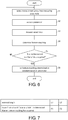
- FIG. 6 is a flowchart showing the processing in the method for setting bottom-touching-determination standard according to the present embodiment.
- the measurement screw 11 is screwed into the measurement screw hole 13a by the screw tightening device (S1, screwing step).
- the standard setting device acquires the parameters in the screw tightening process (S2, parameter acquisition step).
- the standard setting device measures, by the load cell 14, the axial force of the measurement screw 11 applied between the bearing surface of the measurement screw 11 and the screw hole member 13 (S3, axial force measurement step).
- the standard setting device determines the presence or absence of bottom-touching on the basis of the measured axial force (S4, bottom-touching-determination step).
- the standard setting device determines whether the parameter acquisition and bottom-touching measurement have been performed on a given number of screws (S5).
- the standard setting device collates the determination result in the bottom-touching-determination step with the parameters and thereby sets the bottom-touching-determination standard based on parameters (S6, determination standard setting step).
- the standard setting device again performs steps S1 through S4 for the other screws.
- the predetermined number an appropriate number may be appropriately set by the user of the standard setting device for setting the determination standard, and may be 35 for example.
- the standard setting device can set the bottom-touching-determination standard based on parameters with high reliability.
- FIG. 7 is a diagram showing an example of a table referred to by the standard setting device.
- the standard setting device determines the presence or absence of bottom-touching by referring to the table showing the relationship between the length at which the measurement screw 11 is screwed into the measurement screw hole 13a and the range of the axial force for determining that bottom-touching has not occurred.
- the length at which the measurement screw 11 is screwed into the measurement screw hole 13a is L1
- the lower limit of the axial force for determining that bottom-touching has not occurred is F1
- the range of the axial force for determining that bottom-touching has not occurred is F1 or more.
- the lower limit of the axial force for determining that bottom-touching has not occurred is F2
- the range of the axial force for determining that no bottom-touching has occurred is F2 or more.
- the axial force due to the fastening of the screw changes according to the length at which the screw is screwed into the screw hole.
- the standard setting device can refer to the table as shown in FIG. 7 to determine the presence or absence of bottom-touching, and thereby determine the bottom-touching corresponding to the length at which the screw is screwed into the screw hole.
- the table because the range of the axial force in which it can be determined that the bottom-touching has not occurred is taken into consideration, the influence of the variation of the axial force on the determination of the presence or absence of the bottom-touching can be reduced.
- the standard setting device of the standard setting system 1 may be realized by a logic circuit (hardware) formed in an integrated circuit (IC chip) or the like, or may be realized by software.
- the standard setting system 1 includes a computer that executes the instructions of a program that is software for realizing each function.
- the computer includes, for example, one or more processors and a computer-readable recording medium in which the above program is stored. Then, in the computer, the processor reads the program from the recording medium and executes the program, thereby achieving the object of the disclosure.
- the processor for example, a central processing unit (CPU) can be used.
- the recording medium a "non-temporary tangible medium", for example, a read only memory (ROM) or the like, a tape, a disk, a card, a semiconductor memory, a programmable logic circuit, or the like can be used.
- a random access memory (RAM) for expanding the above program may be further included.
- the program may be supplied to the computer via an arbitrary transmission medium (communication network, broadcast wave, etc.) capable of transmitting the program.
- a transmission medium communication network, broadcast wave, etc.
- one aspect of the disclosure can also be realized in the form of a data signal embedded in a carrier wave, in which the above program is embodied by electronic transmission.
- the method for setting bottom-touching-determination standard sets a standard for determining bottom-touching in screw tightening.
- a measuring system which includes a screw hole member having a measurement screw hole of a predetermined depth and an axial force measuring device that measures a compressive force applied between the screw hole member and a bearing surface of a measurement screw screwed into the measurement screw hole.
- the method includes: a screwing step of screwing the measurement screw into the measurement screw hole; a parameter acquisition step of acquiring parameters in the screwing step; an axial force measurement step of measuring the axial force of the measurement screw applied between the bearing surface and the screw hole member by the axial force measuring device; a bottom-touching-determination step of determining the presence or absence of bottom-touching on the basis of the axial force; and a determination standard setting step of setting a bottom-touching-determination standard based on the parameters by collating the determination result in the bottom-touching-determination step with the parameters acquired in the parameter acquisition step.
- the parameters in the screwing step of screwing the measurement screw into the measurement screw hole are acquired.
- the presence or absence of bottom-touching is determined on the basis of the axial force of the measurement screw applied between the bearing surface of the measurement screw and the screw hole member.
- the bottom-touching-determination is performed on the basis of the highly precise axial force measurement result, and the bottom-touching-determination standard based on parameters is set by collating the determination result with the parameters.
- the bottom-touching-determination based on parameters for which the bottom-touching-determination standard is set as described above can be evaluated as having high reliability. Therefore, the bottom-touching-determination standard based on parameters can be set with high reliability.
- the presence or absence of bottom-touching is determined by referring to the table showing the relationship between the length at which the measurement screw is screwed into the measurement screw hole and the range of the axial force in which it can be determined that bottom-touching has not occurred.
- the axial force due to the fastening of the screw changes according to the length at which the screw is screwed into the screw hole when the conditions such as the material of the screw and the friction coefficient of the bearing surface are the same.
- the program according to one aspect of the disclosure causes a computer to execute the parameter acquisition step, the axial force measurement step, the bottom-touching-determination step, and the determination standard setting step.
Landscapes
- Physics & Mathematics (AREA)
- General Physics & Mathematics (AREA)
- Engineering & Computer Science (AREA)
- Mechanical Engineering (AREA)
- Acoustics & Sound (AREA)
- Chemical & Material Sciences (AREA)
- Combustion & Propulsion (AREA)
- Force Measurement Appropriate To Specific Purposes (AREA)
- Details Of Spanners, Wrenches, And Screw Drivers And Accessories (AREA)
Abstract
Description
- The disclosure relates to a method for setting bottom-touching-determination standard used to determine a bottom-touching defect in screw tightening.
- If a float such as bottom-touching occurs when screws are tightened by a screw tightening device, no axial force is generated, so that an appropriate fastening force cannot be obtained. If there is a gap between the bearing surface of the screw and the object to be fastened, it can be detected that bottom-touching has occurred, but sometimes bottom-touching occurs even when there is no gap between the bearing surface of the screw and the object to be fastened. Such bottom-touching can be detected by measuring the axial force of the screw.
-
Patent literature 1 discloses a nut runner with an axial force meter. The nut runner with an axial force meter includes a probe having a vibration generator that vibrates the bolt head vertically by an electromagnetic force and a vibration detector that detects the vertical vibration, converts the vibration into a signal and outputs the signal. The nut runner with an axial force meter generates vibration in the bolt by the vibration generator, detects the vibration with the vibration detector, processes the detection signal with a control device to calculate the resonance frequency, and makes an association with the bolt axial force (bolt tightening force). - Patent Literature 1: Japanese Patent Publication "
Japanese Patent Laid-open No. 2004-291217 - However, because the nut runner with an axial force meter disclosed in
Patent literature 1 includes a probe for measuring the axial force, there is a problem that the number of parts and the cost increase as compared with a normal nut runner. In order to determine the presence or absence of bottom-touching without increasing the number of parts and the cost of the nut runner, it is preferable that bottom-touching can be detected according to parameters based on measured values obtained in a normal nut runner without an axial force meter. - In addition, in the approach disclosed in
Patent literature 1, the vibration generator generates vibration in the bolt, the vibration is detected by the vibration detector, the detection signal is processed by the control device to calculate the resonance frequency, and an associating is made with the bolt axial force to thereby measure the axial force. In this case, because the axial force is indirectly measured, the precision of the measurement result is low and there is a possibility of erroneous determination. - One aspect of the disclosure aims to provide a method for setting bottom-touching-determination standard which is capable of setting a bottom-touching-determination standard based on parameters with high reliability.
- In order to solve the above problems, the method for setting bottom-touching-determination standard according to one aspect of the disclosure sets a standard for determining bottom-touching in screw tightening. In the method, a measuring system is used which includes a screw hole member having a measurement screw hole of a predetermined depth and an axial force measuring device that measures a compressive force applied between the screw hole member and a bearing surface of a measurement screw screwed into the measurement screw hole. The method includes: a screwing step of screwing the measurement screw into the measurement screw hole; a parameter acquisition step of acquiring parameters in the screwing step; an axial force measurement step of measuring the axial force of the measurement screw applied between the bearing surface and the screw hole member by the axial force measuring device; a bottom-touching-determination step of determining the presence or absence of bottom-touching on the basis of the axial force; and a determination standard setting step of setting a bottom-touching-determination standard based on the parameters by collating the determination result in the bottom-touching-determination step with the parameters acquired in the parameter acquisition step.
- According to the method for setting bottom-touching-determination standard according to one aspect of the disclosure, the bottom-touching-determination standard based on parameters can be set with high reliability.
-
-
FIG. 1 is a diagram showing an example of a standard setting system for executing a method for setting bottom-touching-determination standard according to the present embodiment. -
FIG. 2 is a diagram showing an example of the state of a screw-tightened fastening screw, in which (a) is a diagram showing the state in which the bearing surface is floating from the object to be fastened, and (b) is a diagram showing the state in which the bearing surface is in contact with the object to be fastened.- (a) and (b) of
FIG. 3 are diagrams for illustrating the outline of the method for setting bottom-touching-determination standard according to the present embodiment.
- (a) and (b) of
-
FIG. 4 is a graph showing the results of measuring axial forces with load cells for four types of screws. -
FIG. 5 is a graph showing an example of setting a bottom-touching-determination standard by the method for setting bottom-touching-determination standard according to the present embodiment. -
FIG. 6 is a flowchart showing processing in the method for setting bottom-touching-determination standard according to the present embodiment. -
FIG. 7 is a diagram showing an example of a table referred to by a standard setting device. - Hereinafter, an embodiment according to one aspect of the disclosure (hereinafter, also referred to as "the present embodiment") is described with reference to the drawings.
-
FIG. 2 is a diagram showing an example of the state in which an object to be fastened 102 is fastened to afastening object 103 by afastening screw 101, in which (a) is a diagram showing the state in which the bearing surface is floating from the object to be fastened 102, and (b) is a diagram showing the state in which the bearing surface is in contact with the object to be fastened 102. - During screw tightening, if a screw that is longer than the screw that should be used is accidentally used, if the screw hole is shallow, or if foreign matter has entered the screw hole, a defect called bottom-touching may occur, that is, the front end of the screw may come into contact with the bottom of the screw hole during screw tightening. When such a defect occurs, the screw does not exert a sufficient fastening force even though a specified torque is applied by the front end of the screw reaching the bottom of the screw hole.
- As shown in (a) of
FIG. 2 , if the bearing surface of thefastening screw 101 is not in contact with the object to be fastened 102, the distance d between the bearing surface and the object to be fastened W can be measured. In this way, if the distance d can be measured, it can be determined that bottom-touching has occurred. On the other hand, as shown in (b) ofFIG. 2 , bottom-touching may occur even when the bearing surface of thefastening screw 101 is not in contact with the object to be fastened 102. However, in the state shown inFIG. 2 , the presence or absence of bottom-touching cannot be determined depending on the distance d. - (a) and (b) of
FIG. 3 are diagrams for illustrating the outline of the method for setting bottom-touching-determination standard according to the present embodiment. In the present embodiment, as shown in (a) ofFIG. 3 , measurement is made on the axial force of thefastening screw 101 in a state that thefastening screw 101 is screwed into thefastening object 103 by a length L and the object to be fastened 102 is fastened to thefastening object 103. However, when thefastening screw 101 actually fastens the object to be fastened 102 to thefastening object 103, it is necessary to use an expensive device such as an ultrasonic sensor to measure the axial force. In addition, because the ultrasonic sensor does not directly measure the axial force, the measurement precision may be lowered. - In the present embodiment, as shown in (b) of
FIG. 3 , the axial force in the state that the object to be fastened 102 is fastened to ascrew hole member 13 by ameasurement screw 11 is measured by a load cell 14 (axial force measuring device) arranged between the object to be fastened 102 and thescrew hole member 13. Thescrew hole member 13 has ameasurement screw hole 13a having a predetermined depth. Theload cell 14 measures the compressive force applied between thebearing surface 11a of themeasurement screw 11 screwed into themeasurement screw hole 13a and thescrew hole member 13. According to the method shown in (b) ofFIG. 3 , the compressive force applied between thebearing surface 11a of themeasurement screw 11 and thescrew hole member 13, that is, the axial force can be directly measured, so that highly precise measurement can be performed. -
FIG. 4 is a graph showing the results of measuring the axial force by theload cell 14 for four types of screws. In the graph shown inFIG. 4 , the vertical axis indicates the axial force, and the horizontal width indicates the distribution (probability density) when the measurement is performed a plurality of times. InFIG. 4 , the following axial forces are shown in order from the left. - (A) The axial force of the
measurement screw 11 as a sample, which is known to have sufficient fastening force - (B) The axial force (1) of the screw of which the bearing surface is in contact with the object to be fastened as a result of screw tightening
- (C) The axial force (2) of the screw of which the bearing surface is in contact with the object to be fastened as a result of screw tightening
- (D) The axial force of the screw of which the bearing surface is not in contact with the object to be fastened as a result of screw tightening
- In the method for setting bottom-touching-determination standard according to the present embodiment, among the four types of graphs shown in
FIG. 4 , for the axial force of the screw having the axial force as shown in the graphs (A) or (B), it is determined that no bottom-touching occurs. On the other hand, for the axial force of the screw having the axial force as shown in the graph of (C) or (D), it is determined that bottom-touching occurs. - Because the bearing surface is in contact with the object to be fastened for the axial force of the screw in the case of both (B) and (C), it is not possible to determine the presence or absence of bottom-touching by the distance d between the bearing surface and the object to be fastened. However, by determining the presence or absence of bottom-touching on the basis of the axial force, as described above, it can be determined that the screw having the axial force of (B) has no bottom-touching and the screw having the axial force of (C) has bottom-touching.
- In the method of setting bottom-touching-determination standard according to the present embodiment, an attempt is made to set the bottom-touching-determination standard based on parameters in screw tightening by collating the parameters with the presence or absence of bottom-touching determined on the basis of the axial force. Then, depending on whether or not the bottom-touching-determination standard can be set, it is determined whether or not the parameters are appropriate as the parameters for determining the presence or absence of bottom-touching.
-
FIG. 1 is a diagram showing an example of astandard setting system 1 for executing the method for setting bottom-touching-determination standard according to the present embodiment. As shown inFIG. 1 , thestandard setting system 1 includes themeasurement screw 11, the object to be fastened 102, ameasuring system 2, and aflanged washer 15. In addition, thestandard setting system 1 further includes a standard setting device (not shown) for setting a standard for parameters, and a screw tightening device (not shown) for tightening themeasurement screw 11. The measuringsystem 2 includes thescrew hole member 13 and theload cell 14 described above. - The
flanged washer 15 is an annular member arranged above and below theload cell 14 while surrounding themeasurement screw 11. Therefore, theload cell 14 abuts against the object to be fastened 102 via theflanged washer 15 arranged on the upper side, and abuts against thescrew hole member 13 via theflanged washer 15 arranged on the lower side. - The
measurement screw 11 is longer than thefastening screw 101 by the thickness of theload cell 14 and theflanged washer 15. In addition, the length L at which themeasurement screw 11 is screwed into thescrew hole member 13 is equal to the length L at which thefastening screw 101 is screwed into thefastening object 103. Therefore, the parameters in the screw tightening process of themeasurement screw 11 and the axial force at the completion of screw tightening are equal to the parameters in the screw tightening process of thefastening screw 101 and the axial force at the completion of screw tightening, respectively. - The screw tightening device performs screw tightening in which the
measurement screw 11 is screwed into themeasurement screw hole 13a. The screw tightening device is controlled by the standard setting device. The standard setting device executes the method for setting bottom-touching-determination standard that sets a standard for determining bottom-touching in screw tightening. -
FIG. 5 is a graph showing an example in which the bottom-touching-determination standard is set by the method for setting bottom-touching-determination standard according to the present embodiment. In the example shown inFIG. 5 , the maximum value of the position of the driver in the axial direction is used as a parameter for setting the standard. InFIG. 5 , the horizontal axis shows the floating of the bearing surface of themeasurement screw 11 from the object to be fastened 102, and the vertical axis shows the maximum value of the position of the driver in the axial direction in the screw tightening process. In the following description, the floating of the bearing surface of themeasurement screw 11 from the object to be fastened 102 may be simply referred to as "floating of the bearing surface". In addition, in the graph shown inFIG. 5 , the region where the data points exist is divided into regions R1 and R2. Furthermore, the region R1 is divided into regions R11 and R12. - The region R2 is a region including all data points whose bearing surface floating is larger than 0 mm. Bottom-touching occurred in all the screws with data points in the region R2.
- The region R1 is a region including all the data points where the floating of the bearing surface is 0 mm. Of the screws whose data points are included in the region R1, no bottom-touching occurred in the screws whose data points are included in the region R11. On the other hand, bottom-touching occurred in all the screws whose data points are included in the region R12.
- The regions R11 and R12 are divided with the threshold value TH as a boundary for the maximum value of the position of the driver in the axial direction. In addition, the maximum values of the position of the driver in the axial direction for the data points included in the region R2 are all less than the threshold value TH. Therefore, it is possible to determine whether or not the screw has a fastening force depending on whether or not the maximum value of the position of the driver in the axial direction is equal to or greater than the threshold value TH. That is, the standard setting device can set the threshold value TH as the bottom-touching-determination standard for the maximum value of the position of the driver in the axial direction.
- In addition to the maximum value of the position of the driver in the axial direction, for the average value or the minimum value of the position, the standard setting device may also set the bottom-touching-determination standard according to the method for setting bottom-touching-determination standard of the present embodiment as a parameter for making a determination in view of the axial force in screw tightening. In addition, the standard setting device may set the bottom-touching-determination standard as a parameter for making a determination in view of the axial force in screw tightening for the average value, the maximum value, or the minimum value of the moving speed, the rotation speed, or the rotation amount in the axial direction of the driver.
- Moreover, depending on the type of the parameter, it may not be possible to set a bottom-touching-determination standard such as the threshold value TH. In that case, the standard setting device evaluates that the parameter is not appropriate as a parameter for determining whether or not the screw has bottomed touch.
-
FIG. 6 is a flowchart showing the processing in the method for setting bottom-touching-determination standard according to the present embodiment. First, in the standard setting device, themeasurement screw 11 is screwed into themeasurement screw hole 13a by the screw tightening device (S1, screwing step). Next, the standard setting device acquires the parameters in the screw tightening process (S2, parameter acquisition step). Subsequently, the standard setting device measures, by theload cell 14, the axial force of themeasurement screw 11 applied between the bearing surface of themeasurement screw 11 and the screw hole member 13 (S3, axial force measurement step). Furthermore, the standard setting device determines the presence or absence of bottom-touching on the basis of the measured axial force (S4, bottom-touching-determination step). - The standard setting device then determines whether the parameter acquisition and bottom-touching measurement have been performed on a given number of screws (S5). When the acquisition of parameters and the measurement of bottom-touching are performed for a predetermined number of screws (YES in S5), the standard setting device collates the determination result in the bottom-touching-determination step with the parameters and thereby sets the bottom-touching-determination standard based on parameters (S6, determination standard setting step). On the other hand, if the parameter acquisition and bottom-touching measurement have not been performed for a given number of screws (NO in S5), the standard setting device again performs steps S1 through S4 for the other screws. As for the predetermined number, an appropriate number may be appropriately set by the user of the standard setting device for setting the determination standard, and may be 35 for example.
- According to the method for setting bottom-touching-determination standard according to the present embodiment, the standard setting device can set the bottom-touching-determination standard based on parameters with high reliability.
-
FIG. 7 is a diagram showing an example of a table referred to by the standard setting device. In the bottom-touching-determination step described above, the standard setting device determines the presence or absence of bottom-touching by referring to the table showing the relationship between the length at which themeasurement screw 11 is screwed into themeasurement screw hole 13a and the range of the axial force for determining that bottom-touching has not occurred. InFIG. 7 , it is shown that when the length at which themeasurement screw 11 is screwed into themeasurement screw hole 13a is L1, the lower limit of the axial force for determining that bottom-touching has not occurred is F1, that is, the range of the axial force for determining that bottom-touching has not occurred is F1 or more. Similarly, it is shown that when the length at which themeasurement screw 11 is screwed into themeasurement screw hole 13a is L2, the lower limit of the axial force for determining that bottom-touching has not occurred is F2, that is, the range of the axial force for determining that no bottom-touching has occurred is F2 or more. - The axial force due to the fastening of the screw changes according to the length at which the screw is screwed into the screw hole. The standard setting device can refer to the table as shown in
FIG. 7 to determine the presence or absence of bottom-touching, and thereby determine the bottom-touching corresponding to the length at which the screw is screwed into the screw hole. In the table, because the range of the axial force in which it can be determined that the bottom-touching has not occurred is taken into consideration, the influence of the variation of the axial force on the determination of the presence or absence of the bottom-touching can be reduced. - The standard setting device of the
standard setting system 1 may be realized by a logic circuit (hardware) formed in an integrated circuit (IC chip) or the like, or may be realized by software. - In the latter case, the
standard setting system 1 includes a computer that executes the instructions of a program that is software for realizing each function. The computer includes, for example, one or more processors and a computer-readable recording medium in which the above program is stored. Then, in the computer, the processor reads the program from the recording medium and executes the program, thereby achieving the object of the disclosure. As the processor, for example, a central processing unit (CPU) can be used. As the recording medium, a "non-temporary tangible medium", for example, a read only memory (ROM) or the like, a tape, a disk, a card, a semiconductor memory, a programmable logic circuit, or the like can be used. In addition, a random access memory (RAM) for expanding the above program may be further included. In addition, the program may be supplied to the computer via an arbitrary transmission medium (communication network, broadcast wave, etc.) capable of transmitting the program. Moreover, one aspect of the disclosure can also be realized in the form of a data signal embedded in a carrier wave, in which the above program is embodied by electronic transmission. - The disclosure is not limited to the above-described embodiments, and various modifications can be made within the scope of the claims. The embodiments obtained by appropriately combining the technical means disclosed in different embodiments are also included in the technical scope of the disclosure.
- As described above, the method for setting bottom-touching-determination standard according to one aspect of the disclosure sets a standard for determining bottom-touching in screw tightening. In the method, a measuring system is used which includes a screw hole member having a measurement screw hole of a predetermined depth and an axial force measuring device that measures a compressive force applied between the screw hole member and a bearing surface of a measurement screw screwed into the measurement screw hole. The method includes: a screwing step of screwing the measurement screw into the measurement screw hole; a parameter acquisition step of acquiring parameters in the screwing step; an axial force measurement step of measuring the axial force of the measurement screw applied between the bearing surface and the screw hole member by the axial force measuring device; a bottom-touching-determination step of determining the presence or absence of bottom-touching on the basis of the axial force; and a determination standard setting step of setting a bottom-touching-determination standard based on the parameters by collating the determination result in the bottom-touching-determination step with the parameters acquired in the parameter acquisition step.
- According to the above configuration, first, the parameters in the screwing step of screwing the measurement screw into the measurement screw hole are acquired. In addition, the presence or absence of bottom-touching is determined on the basis of the axial force of the measurement screw applied between the bearing surface of the measurement screw and the screw hole member.
- Here, because the axial force is measured by measuring the compressive force applied between the bearing surface of the measurement screw and the screw hole member, highly precise measurement can be performed. The bottom-touching-determination is performed on the basis of the highly precise axial force measurement result, and the bottom-touching-determination standard based on parameters is set by collating the determination result with the parameters. The bottom-touching-determination based on parameters for which the bottom-touching-determination standard is set as described above can be evaluated as having high reliability. Therefore, the bottom-touching-determination standard based on parameters can be set with high reliability.
- Further, in the method for setting bottom-touching-determination standard according to one aspect of the disclosure, in the bottom-touching-determination step, the presence or absence of bottom-touching is determined by referring to the table showing the relationship between the length at which the measurement screw is screwed into the measurement screw hole and the range of the axial force in which it can be determined that bottom-touching has not occurred.
- The axial force due to the fastening of the screw changes according to the length at which the screw is screwed into the screw hole when the conditions such as the material of the screw and the friction coefficient of the bearing surface are the same. In view of this, according to the above configuration, it is possible to perform bottom-touching-determination corresponding to the length at which the screw is screwed into the screw hole. Because the range of the axial force in which it can be determined that the bottom-touching has not occurred is taken into consideration, the influence of the variation in the axial force on the determination of the presence or absence of bottom-touching can be reduced.
- In addition, the program according to one aspect of the disclosure causes a computer to execute the parameter acquisition step, the axial force measurement step, the bottom-touching-determination step, and the determination standard setting step.
-
- 2
- measuring system
- 11
- measurement screw
- 11a
- bearing surface
- 13
- screw hole member
- 13a
- measurement screw hole
- 14
- load cell (axial force measuring device)
Claims (3)
- A method for setting bottom-touching-determination standard which makes a determination in view of an axial force in screw tightening, whereina measuring system is used which comprises a screw hole member having a measurement screw hole of a predetermined depth and an axial force measuring device that measures a compressive force applied between the screw hole member and a bearing surface of a measurement screw screwed into the measurement screw hole, andthe method for setting bottom-touching-determination standard comprises:a screwing step of screwing the measurement screw into the measurement screw hole;a parameter acquisition step of acquiring parameters in the screwing step;an axial force measurement step of measuring the axial force of the measurement screw applied between the bearing surface and the screw hole member by the axial force measuring device;a bottom-touching-determination step of determining the presence or absence of bottom-touching on the basis of the axial force; anda determination standard setting step of setting a bottom-touching-determination standard based on the parameters by collating a determination result in the bottom-touching-determination step with the parameters acquired in the parameter acquisition step.
- The method for setting bottom-touching-determination standard according to claim 1, wherein in the bottom-touching-determination step, the presence or absence of bottom-touching is determined by referring to a table showing the relationship between a length at which the measurement screw is screwed into the measurement screw hole and a range of the axial force in which it is determined that bottom-touching has not occurred.
- A program for causing a computer to execute the method for setting bottom-touching-determination standard according to claim 1, wherein the program causes the computer to execute the parameter acquisition step, the axial force measurement step, the bottom-touching-determination step, and the determination standard setting step.
Applications Claiming Priority (2)
| Application Number | Priority Date | Filing Date | Title |
|---|---|---|---|
| JP2018203048A JP6973352B2 (en) | 2018-10-29 | 2018-10-29 | Bottoming judgment standard setting method |
| PCT/JP2019/037510 WO2020090293A1 (en) | 2018-10-29 | 2019-09-25 | Method for setting bottom-touching-determination standard |
Publications (3)
| Publication Number | Publication Date |
|---|---|
| EP3875935A1 true EP3875935A1 (en) | 2021-09-08 |
| EP3875935A4 EP3875935A4 (en) | 2022-09-28 |
| EP3875935B1 EP3875935B1 (en) | 2024-11-27 |
Family
ID=70463429
Family Applications (1)
| Application Number | Title | Priority Date | Filing Date |
|---|---|---|---|
| EP19879680.7A Active EP3875935B1 (en) | 2018-10-29 | 2019-09-25 | Method for setting bottom-touching-determination standard and program therefor |
Country Status (6)
| Country | Link |
|---|---|
| US (1) | US11759898B2 (en) |
| EP (1) | EP3875935B1 (en) |
| JP (1) | JP6973352B2 (en) |
| KR (1) | KR102397437B1 (en) |
| CN (1) | CN112654847B (en) |
| WO (1) | WO2020090293A1 (en) |
Family Cites Families (23)
| Publication number | Priority date | Publication date | Assignee | Title |
|---|---|---|---|---|
| JPS6144582A (en) * | 1984-08-07 | 1986-03-04 | マツダ株式会社 | Method of discriminating acceptable or defective plastic clamping in nut runner |
| JPS6291609U (en) | 1985-11-29 | 1987-06-11 | ||
| JP2944004B2 (en) | 1991-04-30 | 1999-08-30 | 日立建機株式会社 | Ultrasonic bolt axial force measuring device |
| US5549169A (en) * | 1993-01-13 | 1996-08-27 | Nippondenso Co., Ltd. | Screw tightening apparatus |
| DE4400709B4 (en) * | 1993-01-13 | 2005-06-23 | Denso Corp., Kariya | Screw fastening device |
| JP2953292B2 (en) * | 1994-02-07 | 1999-09-27 | 株式会社デンソー | Screw fastening device |
| US6782594B2 (en) * | 1997-12-30 | 2004-08-31 | Ralph S. Shoberg | Method and apparatus for auditing a tension load in the threaded fastener |
| US6501211B1 (en) * | 2001-07-13 | 2002-12-31 | Masoud Nasrollahzadeh | Ultra-sonic transducer assembly incorporated into a printed circuit board for determining tension forces in a bolt |
| JP3719240B2 (en) * | 2002-08-30 | 2005-11-24 | いすゞ自動車株式会社 | Bolt axial force measuring device |
| JP4329377B2 (en) * | 2003-03-28 | 2009-09-09 | センサ・システム株式会社 | Nut runner with axial force meter |
| FR2871231B1 (en) * | 2004-06-02 | 2006-09-15 | Skf Ab | METHOD FOR CONTROLLING THE TENSIONING OF A ROD, OF THE TYPE OF SCREW OR ASSEMBLY PIN, AND DEVICE FOR IMPLEMENTING SUCH A METHOD |
| DE102005044917A1 (en) | 2005-09-20 | 2007-04-19 | As Tech Industrie- Und Spannhydraulik Gmbh | Arrangement for recording measured variables in screw connections |
| WO2007099628A1 (en) * | 2006-03-01 | 2007-09-07 | Fujitsu Limited | System and method for controlling screw tightening |
| JP2011073105A (en) * | 2009-09-30 | 2011-04-14 | Fujitsu Peripherals Ltd | Management method and device of screwing-in quantity of screw |
| JP5618406B2 (en) * | 2010-02-01 | 2014-11-05 | 有限会社井出計器 | Screw tightening diagnosis device and electric driver |
| JP5733122B2 (en) | 2011-09-12 | 2015-06-10 | 株式会社デンソーウェーブ | Screw fastening device and screw floating determination method |
| CN103364129B (en) | 2013-07-31 | 2015-09-09 | 潍柴动力股份有限公司 | A kind of threaded fastener axle force measuring method and measurement mechanism thereof |
| JP6166222B2 (en) | 2014-05-20 | 2017-07-19 | 株式会社ダイセル | Flange fastening skill judgment device and flange fastening skill judgment program |
| CN105606289A (en) * | 2016-03-17 | 2016-05-25 | 西北工业大学 | Bolt tightening torque coefficient measuring device |
| KR101842048B1 (en) * | 2016-10-11 | 2018-05-14 | (주)이큐브시스템 | Axial force and friction torque measurement apparatus and method for identify the coefficient of friction of screw using the same |
| JP6291609B1 (en) * | 2017-03-24 | 2018-03-14 | 日東工器株式会社 | Electric driver control device that can be set automatically |
| CN108458825A (en) | 2018-02-28 | 2018-08-28 | 易克威系统株式会社 | The axial force and friction torque measuring device of screw and the measurement method for utilizing the device |
| JP7443931B2 (en) * | 2020-05-27 | 2024-03-06 | コニカミノルタ株式会社 | Screw tightening device and screw tightening method |
-
2018
- 2018-10-29 JP JP2018203048A patent/JP6973352B2/en active Active
-
2019
- 2019-09-25 WO PCT/JP2019/037510 patent/WO2020090293A1/en not_active Ceased
- 2019-09-25 CN CN201980057515.6A patent/CN112654847B/en active Active
- 2019-09-25 US US17/278,324 patent/US11759898B2/en active Active
- 2019-09-25 EP EP19879680.7A patent/EP3875935B1/en active Active
- 2019-09-25 KR KR1020217007435A patent/KR102397437B1/en active Active
Also Published As
| Publication number | Publication date |
|---|---|
| EP3875935B1 (en) | 2024-11-27 |
| EP3875935A4 (en) | 2022-09-28 |
| KR20210040443A (en) | 2021-04-13 |
| JP2020071056A (en) | 2020-05-07 |
| KR102397437B1 (en) | 2022-05-12 |
| US20210346995A1 (en) | 2021-11-11 |
| US11759898B2 (en) | 2023-09-19 |
| CN112654847A (en) | 2021-04-13 |
| JP6973352B2 (en) | 2021-11-24 |
| CN112654847B (en) | 2022-05-03 |
| WO2020090293A1 (en) | 2020-05-07 |
Similar Documents
| Publication | Publication Date | Title |
|---|---|---|
| EP3318899B1 (en) | Seismic sensor and earthquake determination method | |
| US7536571B2 (en) | System and method to maintain data processing system operation in degraded system cooling condition | |
| US9465373B2 (en) | Dynamic adjustment of operational parameters to compensate for sensor based measurements of circuit degradation | |
| EP2613207A2 (en) | Adaptive trend-change detection and function fitting system and method | |
| CN113835016B (en) | DDR chip limit performance test method, test device, equipment and storage medium | |
| KR20230039873A (en) | Method for detecting abnormality | |
| EP3534180A1 (en) | Determination device and control method of determination device | |
| US9399997B2 (en) | Method for detecting heat-dissipating air flow and electronic device using the same | |
| US20250167050A1 (en) | Local thermal sensing for system monitoring and control | |
| US20110196628A1 (en) | Deterioration detection circuit | |
| JP7322979B2 (en) | Vibration treatment device, vibration treatment method, and program | |
| JP5116307B2 (en) | Integrated circuit device abnormality detection device, method and program | |
| EP3875935B1 (en) | Method for setting bottom-touching-determination standard and program therefor | |
| US20100064149A1 (en) | Voltage adjusting system and method for motherboard components of a computer | |
| KR20150082976A (en) | Method for analyzing wafer yield rate using sensor data in semiconductor manufacturing process | |
| EP3736737B1 (en) | Transponder and method of operating the same | |
| US7363190B2 (en) | Sensor control circuit | |
| WO2025220456A1 (en) | Seismic sensor, earthquake detection method, and earthquake detection program | |
| US10715148B1 (en) | Transient sensing circuitry | |
| US20240009790A1 (en) | Method of monitoring machine tool and method of determining a standard for evaluating abnormality of a machine tool | |
| JPH029554A (en) | Cutting tool damage detecting device | |
| JP5631600B2 (en) | Semiconductor device and pulse width detection method | |
| CN115905822B (en) | Strain sensing method for characterizing a device | |
| WO2025220420A1 (en) | Seismic sensor, earthquake detection method, and earthquake detection program | |
| EP4545960A1 (en) | Gas detection using acoustic sensors |
Legal Events
| Date | Code | Title | Description |
|---|---|---|---|
| STAA | Information on the status of an ep patent application or granted ep patent |
Free format text: STATUS: THE INTERNATIONAL PUBLICATION HAS BEEN MADE |
|
| PUAI | Public reference made under article 153(3) epc to a published international application that has entered the european phase |
Free format text: ORIGINAL CODE: 0009012 |
|
| STAA | Information on the status of an ep patent application or granted ep patent |
Free format text: STATUS: REQUEST FOR EXAMINATION WAS MADE |
|
| 17P | Request for examination filed |
Effective date: 20210315 |
|
| AK | Designated contracting states |
Kind code of ref document: A1 Designated state(s): AL AT BE BG CH CY CZ DE DK EE ES FI FR GB GR HR HU IE IS IT LI LT LU LV MC MK MT NL NO PL PT RO RS SE SI SK SM TR |
|
| DAV | Request for validation of the european patent (deleted) | ||
| DAX | Request for extension of the european patent (deleted) | ||
| RAP3 | Party data changed (applicant data changed or rights of an application transferred) |
Owner name: OMRON CORPORATION |
|
| A4 | Supplementary search report drawn up and despatched |
Effective date: 20220830 |
|
| RIC1 | Information provided on ipc code assigned before grant |
Ipc: B23P 5/00 20060101ALI20220824BHEP Ipc: B23P 19/06 20060101ALI20220824BHEP Ipc: B25B 23/00 20060101ALI20220824BHEP Ipc: G01L 5/24 20060101AFI20220824BHEP |
|
| REG | Reference to a national code |
Ref legal event code: R079 Free format text: PREVIOUS MAIN CLASS: G01L0025000000 Ipc: G01L0005240000 Ref country code: DE Ref legal event code: R079 Ref document number: 602019062747 Country of ref document: DE Free format text: PREVIOUS MAIN CLASS: G01L0025000000 Ipc: G01L0005240000 |
|
| GRAP | Despatch of communication of intention to grant a patent |
Free format text: ORIGINAL CODE: EPIDOSNIGR1 |
|
| STAA | Information on the status of an ep patent application or granted ep patent |
Free format text: STATUS: GRANT OF PATENT IS INTENDED |
|
| RIC1 | Information provided on ipc code assigned before grant |
Ipc: B23P 5/00 20060101ALI20240612BHEP Ipc: B23P 19/06 20060101ALI20240612BHEP Ipc: B25B 23/00 20060101ALI20240612BHEP Ipc: G01L 5/24 20060101AFI20240612BHEP |
|
| INTG | Intention to grant announced |
Effective date: 20240702 |
|
| GRAS | Grant fee paid |
Free format text: ORIGINAL CODE: EPIDOSNIGR3 |
|
| GRAA | (expected) grant |
Free format text: ORIGINAL CODE: 0009210 |
|
| STAA | Information on the status of an ep patent application or granted ep patent |
Free format text: STATUS: THE PATENT HAS BEEN GRANTED |
|
| AK | Designated contracting states |
Kind code of ref document: B1 Designated state(s): AL AT BE BG CH CY CZ DE DK EE ES FI FR GB GR HR HU IE IS IT LI LT LU LV MC MK MT NL NO PL PT RO RS SE SI SK SM TR |
|
| REG | Reference to a national code |
Ref country code: GB Ref legal event code: FG4D |
|
| REG | Reference to a national code |
Ref country code: CH Ref legal event code: EP |
|
| REG | Reference to a national code |
Ref country code: IE Ref legal event code: FG4D |
|
| REG | Reference to a national code |
Ref country code: DE Ref legal event code: R096 Ref document number: 602019062747 Country of ref document: DE |
|
| REG | Reference to a national code |
Ref country code: LT Ref legal event code: MG9D |
|
| REG | Reference to a national code |
Ref country code: NL Ref legal event code: MP Effective date: 20241127 |
|
| PG25 | Lapsed in a contracting state [announced via postgrant information from national office to epo] |
Ref country code: HR Free format text: LAPSE BECAUSE OF FAILURE TO SUBMIT A TRANSLATION OF THE DESCRIPTION OR TO PAY THE FEE WITHIN THE PRESCRIBED TIME-LIMIT Effective date: 20241127 Ref country code: PT Free format text: LAPSE BECAUSE OF FAILURE TO SUBMIT A TRANSLATION OF THE DESCRIPTION OR TO PAY THE FEE WITHIN THE PRESCRIBED TIME-LIMIT Effective date: 20250327 Ref country code: IS Free format text: LAPSE BECAUSE OF FAILURE TO SUBMIT A TRANSLATION OF THE DESCRIPTION OR TO PAY THE FEE WITHIN THE PRESCRIBED TIME-LIMIT Effective date: 20250327 |
|
| PG25 | Lapsed in a contracting state [announced via postgrant information from national office to epo] |
Ref country code: FI Free format text: LAPSE BECAUSE OF FAILURE TO SUBMIT A TRANSLATION OF THE DESCRIPTION OR TO PAY THE FEE WITHIN THE PRESCRIBED TIME-LIMIT Effective date: 20241127 Ref country code: NL Free format text: LAPSE BECAUSE OF FAILURE TO SUBMIT A TRANSLATION OF THE DESCRIPTION OR TO PAY THE FEE WITHIN THE PRESCRIBED TIME-LIMIT Effective date: 20241127 |
|
| REG | Reference to a national code |
Ref country code: AT Ref legal event code: MK05 Ref document number: 1746089 Country of ref document: AT Kind code of ref document: T Effective date: 20241127 |
|
| PG25 | Lapsed in a contracting state [announced via postgrant information from national office to epo] |
Ref country code: BG Free format text: LAPSE BECAUSE OF FAILURE TO SUBMIT A TRANSLATION OF THE DESCRIPTION OR TO PAY THE FEE WITHIN THE PRESCRIBED TIME-LIMIT Effective date: 20241127 |
|
| PG25 | Lapsed in a contracting state [announced via postgrant information from national office to epo] |
Ref country code: ES Free format text: LAPSE BECAUSE OF FAILURE TO SUBMIT A TRANSLATION OF THE DESCRIPTION OR TO PAY THE FEE WITHIN THE PRESCRIBED TIME-LIMIT Effective date: 20241127 |
|
| PG25 | Lapsed in a contracting state [announced via postgrant information from national office to epo] |
Ref country code: NO Free format text: LAPSE BECAUSE OF FAILURE TO SUBMIT A TRANSLATION OF THE DESCRIPTION OR TO PAY THE FEE WITHIN THE PRESCRIBED TIME-LIMIT Effective date: 20250227 |
|
| PG25 | Lapsed in a contracting state [announced via postgrant information from national office to epo] |
Ref country code: LV Free format text: LAPSE BECAUSE OF FAILURE TO SUBMIT A TRANSLATION OF THE DESCRIPTION OR TO PAY THE FEE WITHIN THE PRESCRIBED TIME-LIMIT Effective date: 20241127 Ref country code: GR Free format text: LAPSE BECAUSE OF FAILURE TO SUBMIT A TRANSLATION OF THE DESCRIPTION OR TO PAY THE FEE WITHIN THE PRESCRIBED TIME-LIMIT Effective date: 20250228 Ref country code: AT Free format text: LAPSE BECAUSE OF FAILURE TO SUBMIT A TRANSLATION OF THE DESCRIPTION OR TO PAY THE FEE WITHIN THE PRESCRIBED TIME-LIMIT Effective date: 20241127 |
|
| PG25 | Lapsed in a contracting state [announced via postgrant information from national office to epo] |
Ref country code: PL Free format text: LAPSE BECAUSE OF FAILURE TO SUBMIT A TRANSLATION OF THE DESCRIPTION OR TO PAY THE FEE WITHIN THE PRESCRIBED TIME-LIMIT Effective date: 20241127 |
|
| PG25 | Lapsed in a contracting state [announced via postgrant information from national office to epo] |
Ref country code: RS Free format text: LAPSE BECAUSE OF FAILURE TO SUBMIT A TRANSLATION OF THE DESCRIPTION OR TO PAY THE FEE WITHIN THE PRESCRIBED TIME-LIMIT Effective date: 20250227 |
|
| PG25 | Lapsed in a contracting state [announced via postgrant information from national office to epo] |
Ref country code: SM Free format text: LAPSE BECAUSE OF FAILURE TO SUBMIT A TRANSLATION OF THE DESCRIPTION OR TO PAY THE FEE WITHIN THE PRESCRIBED TIME-LIMIT Effective date: 20241127 |
|
| PG25 | Lapsed in a contracting state [announced via postgrant information from national office to epo] |
Ref country code: DK Free format text: LAPSE BECAUSE OF FAILURE TO SUBMIT A TRANSLATION OF THE DESCRIPTION OR TO PAY THE FEE WITHIN THE PRESCRIBED TIME-LIMIT Effective date: 20241127 |
|
| PG25 | Lapsed in a contracting state [announced via postgrant information from national office to epo] |
Ref country code: EE Free format text: LAPSE BECAUSE OF FAILURE TO SUBMIT A TRANSLATION OF THE DESCRIPTION OR TO PAY THE FEE WITHIN THE PRESCRIBED TIME-LIMIT Effective date: 20241127 |
|
| PG25 | Lapsed in a contracting state [announced via postgrant information from national office to epo] |
Ref country code: RO Free format text: LAPSE BECAUSE OF FAILURE TO SUBMIT A TRANSLATION OF THE DESCRIPTION OR TO PAY THE FEE WITHIN THE PRESCRIBED TIME-LIMIT Effective date: 20241127 |
|
| PG25 | Lapsed in a contracting state [announced via postgrant information from national office to epo] |
Ref country code: SK Free format text: LAPSE BECAUSE OF FAILURE TO SUBMIT A TRANSLATION OF THE DESCRIPTION OR TO PAY THE FEE WITHIN THE PRESCRIBED TIME-LIMIT Effective date: 20241127 |
|
| PG25 | Lapsed in a contracting state [announced via postgrant information from national office to epo] |
Ref country code: CZ Free format text: LAPSE BECAUSE OF FAILURE TO SUBMIT A TRANSLATION OF THE DESCRIPTION OR TO PAY THE FEE WITHIN THE PRESCRIBED TIME-LIMIT Effective date: 20241127 |
|
| PG25 | Lapsed in a contracting state [announced via postgrant information from national office to epo] |
Ref country code: IT Free format text: LAPSE BECAUSE OF FAILURE TO SUBMIT A TRANSLATION OF THE DESCRIPTION OR TO PAY THE FEE WITHIN THE PRESCRIBED TIME-LIMIT Effective date: 20241127 |
|
| REG | Reference to a national code |
Ref country code: DE Ref legal event code: R097 Ref document number: 602019062747 Country of ref document: DE |
|
| PG25 | Lapsed in a contracting state [announced via postgrant information from national office to epo] |
Ref country code: SE Free format text: LAPSE BECAUSE OF FAILURE TO SUBMIT A TRANSLATION OF THE DESCRIPTION OR TO PAY THE FEE WITHIN THE PRESCRIBED TIME-LIMIT Effective date: 20241127 |
|
| PLBE | No opposition filed within time limit |
Free format text: ORIGINAL CODE: 0009261 |
|
| STAA | Information on the status of an ep patent application or granted ep patent |
Free format text: STATUS: NO OPPOSITION FILED WITHIN TIME LIMIT |
|
| REG | Reference to a national code |
Ref country code: CH Ref legal event code: L10 Free format text: ST27 STATUS EVENT CODE: U-0-0-L10-L00 (AS PROVIDED BY THE NATIONAL OFFICE) Effective date: 20251008 |
|
| 26N | No opposition filed |
Effective date: 20250828 |
|
| REG | Reference to a national code |
Ref country code: DE Ref legal event code: R119 Ref document number: 602019062747 Country of ref document: DE |
|
| REG | Reference to a national code |
Ref country code: CH Ref legal event code: H13 Free format text: ST27 STATUS EVENT CODE: U-0-0-H10-H13 (AS PROVIDED BY THE NATIONAL OFFICE) Effective date: 20260504 |
|
| PG25 | Lapsed in a contracting state [announced via postgrant information from national office to epo] |
Ref country code: LU Free format text: LAPSE BECAUSE OF NON-PAYMENT OF DUE FEES Effective date: 20250925 |
|
| GBPC | Gb: european patent ceased through non-payment of renewal fee |
Effective date: 20250925 |
|
| REG | Reference to a national code |
Ref country code: BE Ref legal event code: MM Effective date: 20250930 |
|
| PG25 | Lapsed in a contracting state [announced via postgrant information from national office to epo] |
Ref country code: LT Free format text: LAPSE BECAUSE OF FAILURE TO SUBMIT A TRANSLATION OF THE DESCRIPTION OR TO PAY THE FEE WITHIN THE PRESCRIBED TIME-LIMIT Effective date: 20241127 |
|
| PG25 | Lapsed in a contracting state [announced via postgrant information from national office to epo] |
Ref country code: MC Free format text: LAPSE BECAUSE OF FAILURE TO SUBMIT A TRANSLATION OF THE DESCRIPTION OR TO PAY THE FEE WITHIN THE PRESCRIBED TIME-LIMIT Effective date: 20241127 |
|
| PG25 | Lapsed in a contracting state [announced via postgrant information from national office to epo] |
Ref country code: GB Free format text: LAPSE BECAUSE OF NON-PAYMENT OF DUE FEES Effective date: 20250925 |
|
| PG25 | Lapsed in a contracting state [announced via postgrant information from national office to epo] |
Ref country code: DE Free format text: LAPSE BECAUSE OF NON-PAYMENT OF DUE FEES Effective date: 20260401 |
|
| PG25 | Lapsed in a contracting state [announced via postgrant information from national office to epo] |
Ref country code: CH Free format text: LAPSE BECAUSE OF NON-PAYMENT OF DUE FEES Effective date: 20250930 Ref country code: BE Free format text: LAPSE BECAUSE OF NON-PAYMENT OF DUE FEES Effective date: 20250930 Ref country code: IE Free format text: LAPSE BECAUSE OF NON-PAYMENT OF DUE FEES Effective date: 20250925 |
|
| PG25 | Lapsed in a contracting state [announced via postgrant information from national office to epo] |
Ref country code: FR Free format text: LAPSE BECAUSE OF NON-PAYMENT OF DUE FEES Effective date: 20250930 |