EP3875860B1 - A system and a method for reducing temperature of a heat transfer fluid in a heating system - Google Patents
A system and a method for reducing temperature of a heat transfer fluid in a heating system Download PDFInfo
- Publication number
- EP3875860B1 EP3875860B1 EP20161255.3A EP20161255A EP3875860B1 EP 3875860 B1 EP3875860 B1 EP 3875860B1 EP 20161255 A EP20161255 A EP 20161255A EP 3875860 B1 EP3875860 B1 EP 3875860B1
- Authority
- EP
- European Patent Office
- Prior art keywords
- transfer fluid
- heat
- heat transfer
- district heating
- intermediate circuit
- Prior art date
- Legal status (The legal status is an assumption and is not a legal conclusion. Google has not performed a legal analysis and makes no representation as to the accuracy of the status listed.)
- Active
Links
Images


Classifications
-
- F—MECHANICAL ENGINEERING; LIGHTING; HEATING; WEAPONS; BLASTING
- F24—HEATING; RANGES; VENTILATING
- F24D—DOMESTIC- OR SPACE-HEATING SYSTEMS, e.g. CENTRAL HEATING SYSTEMS; DOMESTIC HOT-WATER SUPPLY SYSTEMS; ELEMENTS OR COMPONENTS THEREFOR
- F24D3/00—Hot-water central heating systems
- F24D3/18—Hot-water central heating systems using heat pumps
-
- F—MECHANICAL ENGINEERING; LIGHTING; HEATING; WEAPONS; BLASTING
- F24—HEATING; RANGES; VENTILATING
- F24D—DOMESTIC- OR SPACE-HEATING SYSTEMS, e.g. CENTRAL HEATING SYSTEMS; DOMESTIC HOT-WATER SUPPLY SYSTEMS; ELEMENTS OR COMPONENTS THEREFOR
- F24D10/00—District heating systems
- F24D10/003—Domestic delivery stations having a heat exchanger
-
- F—MECHANICAL ENGINEERING; LIGHTING; HEATING; WEAPONS; BLASTING
- F24—HEATING; RANGES; VENTILATING
- F24D—DOMESTIC- OR SPACE-HEATING SYSTEMS, e.g. CENTRAL HEATING SYSTEMS; DOMESTIC HOT-WATER SUPPLY SYSTEMS; ELEMENTS OR COMPONENTS THEREFOR
- F24D11/00—Central heating systems using heat accumulated in storage masses
- F24D11/02—Central heating systems using heat accumulated in storage masses using heat pumps
- F24D11/0207—Central heating systems using heat accumulated in storage masses using heat pumps district heating system
-
- F—MECHANICAL ENGINEERING; LIGHTING; HEATING; WEAPONS; BLASTING
- F24—HEATING; RANGES; VENTILATING
- F24D—DOMESTIC- OR SPACE-HEATING SYSTEMS, e.g. CENTRAL HEATING SYSTEMS; DOMESTIC HOT-WATER SUPPLY SYSTEMS; ELEMENTS OR COMPONENTS THEREFOR
- F24D2200/00—Heat sources or energy sources
- F24D2200/12—Heat pump
-
- F—MECHANICAL ENGINEERING; LIGHTING; HEATING; WEAPONS; BLASTING
- F24—HEATING; RANGES; VENTILATING
- F24D—DOMESTIC- OR SPACE-HEATING SYSTEMS, e.g. CENTRAL HEATING SYSTEMS; DOMESTIC HOT-WATER SUPPLY SYSTEMS; ELEMENTS OR COMPONENTS THEREFOR
- F24D2200/00—Heat sources or energy sources
- F24D2200/13—Heat from a district heating network
-
- F—MECHANICAL ENGINEERING; LIGHTING; HEATING; WEAPONS; BLASTING
- F24—HEATING; RANGES; VENTILATING
- F24D—DOMESTIC- OR SPACE-HEATING SYSTEMS, e.g. CENTRAL HEATING SYSTEMS; DOMESTIC HOT-WATER SUPPLY SYSTEMS; ELEMENTS OR COMPONENTS THEREFOR
- F24D2220/00—Components of central heating installations excluding heat sources
- F24D2220/06—Heat exchangers
-
- F—MECHANICAL ENGINEERING; LIGHTING; HEATING; WEAPONS; BLASTING
- F24—HEATING; RANGES; VENTILATING
- F24D—DOMESTIC- OR SPACE-HEATING SYSTEMS, e.g. CENTRAL HEATING SYSTEMS; DOMESTIC HOT-WATER SUPPLY SYSTEMS; ELEMENTS OR COMPONENTS THEREFOR
- F24D2220/00—Components of central heating installations excluding heat sources
- F24D2220/08—Storage tanks
-
- Y—GENERAL TAGGING OF NEW TECHNOLOGICAL DEVELOPMENTS; GENERAL TAGGING OF CROSS-SECTIONAL TECHNOLOGIES SPANNING OVER SEVERAL SECTIONS OF THE IPC; TECHNICAL SUBJECTS COVERED BY FORMER USPC CROSS-REFERENCE ART COLLECTIONS [XRACs] AND DIGESTS
- Y02—TECHNOLOGIES OR APPLICATIONS FOR MITIGATION OR ADAPTATION AGAINST CLIMATE CHANGE
- Y02B—CLIMATE CHANGE MITIGATION TECHNOLOGIES RELATED TO BUILDINGS, e.g. HOUSING, HOUSE APPLIANCES OR RELATED END-USER APPLICATIONS
- Y02B30/00—Energy efficient heating, ventilation or air conditioning [HVAC]
- Y02B30/12—Hot water central heating systems using heat pumps
-
- Y—GENERAL TAGGING OF NEW TECHNOLOGICAL DEVELOPMENTS; GENERAL TAGGING OF CROSS-SECTIONAL TECHNOLOGIES SPANNING OVER SEVERAL SECTIONS OF THE IPC; TECHNICAL SUBJECTS COVERED BY FORMER USPC CROSS-REFERENCE ART COLLECTIONS [XRACs] AND DIGESTS
- Y02—TECHNOLOGIES OR APPLICATIONS FOR MITIGATION OR ADAPTATION AGAINST CLIMATE CHANGE
- Y02B—CLIMATE CHANGE MITIGATION TECHNOLOGIES RELATED TO BUILDINGS, e.g. HOUSING, HOUSE APPLIANCES OR RELATED END-USER APPLICATIONS
- Y02B30/00—Energy efficient heating, ventilation or air conditioning [HVAC]
- Y02B30/17—District heating
-
- Y—GENERAL TAGGING OF NEW TECHNOLOGICAL DEVELOPMENTS; GENERAL TAGGING OF CROSS-SECTIONAL TECHNOLOGIES SPANNING OVER SEVERAL SECTIONS OF THE IPC; TECHNICAL SUBJECTS COVERED BY FORMER USPC CROSS-REFERENCE ART COLLECTIONS [XRACs] AND DIGESTS
- Y02—TECHNOLOGIES OR APPLICATIONS FOR MITIGATION OR ADAPTATION AGAINST CLIMATE CHANGE
- Y02E—REDUCTION OF GREENHOUSE GAS [GHG] EMISSIONS, RELATED TO ENERGY GENERATION, TRANSMISSION OR DISTRIBUTION
- Y02E20/00—Combustion technologies with mitigation potential
- Y02E20/14—Combined heat and power generation [CHP]
Definitions
- the invention relates to a system and a method for reducing a temperature of a heat transfer fluid flowing in a return conduit of a district heating grid.
- a district heating grid is used for distributing heat generated in a centralized location. Heat is distributed by conducting heated heat transfer fluid via a feed conduit to a heat consumer. The heat consumer is typically extracting heat from the heat transfer fluid of the feed conduit using a heat exchanger. After being conducted through the heat exchanger the heat transfer fluid is returned to the centralized location via a return conduit.
- the heat transfer fluid in the return conduit often has a too high temperature, e.g. a temperature of 50°C or higher.
- efficiency of the heating service plant heating the heat transfer fluid at the centralized location may be low.
- EP 3 553 396 proposes a district heating receiving station with a heat accumulator and a heat pump, which removes heat from the district heating network at a lower temperature than a used or desired temperature enables.
- the district heating receiving station lowers a return temperature and thereby a heat loss in the return of the district heating network.
- WO 2010/145040 discloses a district energy sharing system (DESS) comprising a thermal energy circuit which circulates and stores thermal energy in water, at least one client building thermally coupled to the circuit and which removes some thermal energy from the circuit ("thermal sink”) and/or deposits some thermal energy into the circuit (“thermal source”), and at least one thermal server plant that can be thermally coupled to external thermal sources and/or sinks (e.g. a geothermal ground source) and whose function is to maintain thermal balance within the DESS.
- DESS district energy sharing system
- WO 2010/102626 discloses a closed loop heating system comprising at least one closed fluid circuit, at least one thermal energy receiving unit and at least one thermal energy releasing unit.
- the closed loop heating system also comprises a heat pump, transferring thermal energy from at least one first part of said fluid circuit to at least one second part of said fluid circuit.
- EP 3 273 169 relates to a heat transfer system.
- the object of the present invention is to provide a system that adequately addresses to the criteria of increasing efficiency at a heating service plant providing a district heating grid with heat.
- a system and a method for reducing a temperature of district heating heat transfer fluid flowing in a return conduit of a district heating grid are provided.
- a system for reducing a temperature of district heating heat transfer fluid flowing in a return conduit of a district heating grid comprising:
- district heating heat transfer fluid Upon the district heating heat transfer fluid has passed through the primary side of the heat exchanger the temperature of the district heating heat transfer fluid may have dropped. Hence, district heating heat transfer fluid routed back to the return conduit may have a reduced temperature.
- the temperature of district heating heat transfer fluid being routed back to the return conduit of the district heating grid may be reduced.
- the efficiency at a heat service plant, configured to heat district heating heat transfer fluid of the district heating grid may improve. This since the efficiency of the heat service plant is dependent on a temperature difference between a temperature of district heat transfer fluid at a district heat transfer fluid infeed of the heat service plant and a temperature of district heat transfer fluid at a district heat transfer fluid outfeed of the heat service plant. Accordingly, with a lower temperature of district heat transfer fluid in the return conduit, the return conduit is ending at the district heat transfer fluid infeed of the heat service plant, the efficiency of the heat service plant may be improved.
- the present system is based on using a combination of passive and active parts.
- passive heat exchange between different hydraulic circuits.
- active is meant an added ability to alter fluid temperatures beyond what just a heat exchanger can achieve. Typically, the fluid temperature is altered by pumping heat between different hydraulic circuits.
- heat pumping is decentralized to the different point of heat outtake. Doing so, it is possible to satisfy local thermal needs without having to distribute sufficiently warm heat transfer fluid for the need, in case of a heating need, which is the case if only passive elements are to be used. This creates totally different degrees of freedom than the rather strict thermal frames that apply on today's district heating grids where only passive elements are used.
- a passive component for primarily take out heat from the distribution grid and using an active component on a secondary side of the passive component, less constraints on the active component of the assembly may be set.
- a passive component e.g. the heat exchanger
- an active component is typically designed to be feed with heat transfer fluid in a fixed temperature range, such a fixed temperature range is typically rather narrow. Passive components are typically not depending on the temperature of heat transfer fluid feed thereto. This is especially useful since the temperature range in the return conduit of the district heating grid may vary greatly.
- the intermediate circuit comprise an energy storage configured to store thermal energy.
- thermal energy from the return conduit of the district heating grid may be stored and used upon request.
- Such a configuration may preserve energy if the heat of the intermediate circuit heat transfer fluid comprises more energy at a point in time than required by the heating circuit at that point in time.
- the energy storage may provide additional energy to the heating circuit if the heat from the intermediate circuit transfer fluid at a point in time comprises less energy than required by the heating circuit at that point in time.
- the intermediate circuit may comprise a first valve configured to provide regulation of the intermediate circuit heat transfer fluid.
- the intermediate circuit may be regulated with regards to the amount of intermediate circuit heat transfer fluid being routed to the heat exchanger.
- the first valve may regulate if the intermediate circuit heat transfer fluid is to be routed through the heat exchanger or to not.
- the intermediate circuit further comprise a second valve configured to control the flow of intermediate circuit heat transfer fluid routed to the energy storage or to the heat pump.
- a second valve configured to control the flow of intermediate circuit heat transfer fluid routed to the energy storage or to the heat pump.
- efficient control of the energy storage may be achieved. For example, if the heating circuit requires less thermal energy than is present in the intermediate circuit heat transfer fluid, the second vale can route the intermediate circuit heat transfer fluid towards the energy storage. If the heating circuit requires the full amount of thermal energy present in the intermediate circuit heat transfer fluid, the second vale can route the intermediate circuit heat transfer fluid towards the heating circuit.
- the system may further comprise a pump configured to route district heating heat transfer fluid of the return conduit of the district heating grid to the heat exchanger.
- the pump may be configured to pump all of the district heating heat transfer fluid in the return conduit through the heat exchanger.
- the pump may be configured to pump a portion of the district heating heat transfer fluid in the return conduit through the heat exchanger.
- a temperature of district heating heat transfer fluid flowing in a return conduit of a district heating grid comprising:
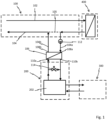
- Fig. 1 shows a system for reducing a temperature of district heating heat transfer fluid flowing in a return conduit 104 of a district heating grid 100.
- the efficiency at a heat service plant configured to heat district heating heat transfer fluid of the district heating grid 100, may improve. This is because the efficiency of the heat service plant is dependent on a temperature difference between a temperature of district heat transfer fluid at a district heat transfer fluid infeed of the heat service plant and a temperature of district heat transfer fluid at a district heat transfer fluid outfeed of the heat service plant.
- the return conduit 104 is ending at the district heat transfer fluid infeed of the heat service plant, the efficiency of the heat service plant may be improved.
- the district heating grid 100 is arranged to circulate district heating heat transfer fluid.
- the district heating grid 100 comprises a feed conduit 102 and the return conduit 104.
- the district heating grid 100 has one or more heat transfer connection to heat consumer(s) 400.
- district heating heat transfer fluid is feed from the heat service plant via the feed conduit 102 to the one or more heat consumer(s) 400.
- heat may be extracted, by means of a consumer heat exchanger, from district heating heat transfer fluid feed to the heat consumer 400 via the feed conduit 102.
- District heating heat transfer fluid feed to the consumer heat exchanger is thereafter returned to the return conduit 104 for return to the heat service plant through the return conduit 104.
- the system for reducing a temperature of district heating heat transfer fluid flowing in the return conduit 104 of the district heating grid 100 comprises a heat exchanger 106 connectable to the return conduit 104 of the district heating grid 100.
- the heat exchanger 106 is connectable to the return conduit 104 at a primary side thereof via a primary side feed conduit 104a connected to a primary side inlet 108a of the heat exchanger 106.
- the heat exchanger 106 is further connectable to the return conduit 104 at the primary side thereof via a primary side return conduit 104b connected to a primary side outlet 108b of the heat exchanger 106.
- district heating heat transfer fluid of the return conduit 104 is routed via the heat exchanger 106.
- an infeed of district heating heat transfer fluid of the return conduit 104 is feed to the heat exchanger 106 via the primary side feed conduit 104a connected to the primary side inlet 108a of the heat exchanger 106.
- District heating heat transfer fluid of the return conduit 104 feed to the heat exchanger 106 is routed back to the return conduit 104 via primary side return conduit 104b connected to the primary side outlet 108b of the heat exchanger 106.
- a portion of the district heating heat transfer fluid in the return conduit 104 may be routed via the heat exchanger 106.
- connection 105 there may be a by-pass connection 105 from a connection point between the primary side feed conduit 104a and the return conduit 104 and a connection point between the primary side return conduit 104b and the return conduit 104.
- all the district heating heat transfer fluid in the return conduit 104 may be routed via the heat exchanger 106.
- the system may further comprise a pump 112 configured to route heating district heating heat transfer fluid from the return conduit 104 to the heat exchanger 106.
- the pump 112 may be arranged in the primary side feed conduit 104a. Alternatively, or in combination, the pump 112 may be arranged in the primary side return conduit 104b. The pump 112 may be controlled so that all or a portion of heating district heating heat transfer fluid is routed from the return conduit 104 to the heat exchanger 106.
- district heating heat transfer fluid returned back to the return conduit 104 will have a lower temperature when being returned to the return conduit 104 than district heating heat transfer fluid routed to the heat exchanger 106.
- the heat exchanger 106 is further, at a secondary side thereof, connected to an intermediate circuit 200.
- the heat exchanger 106 comprises a secondary side inlet 110a and a secondary side outlet 110b.
- the secondary side inlet 110a is connected to the intermediate circuit 200
- the secondary side outlet 110b is connected to the intermediate circuit 200.
- Intermediate circuit heat transfer fluid circulated in the intermediate circuit 200 enters the heat exchanger 106 at the secondary side inlet 110a and exits the heat exchanger 106 at the secondary side outlet 11 0b.
- heat extracted from the district heating transfer fluid at the primary side of the heat exchanger 106 is deposited to the intermediate circuit heat transfer fluid at the secondary side of the heat exchanger 106.
- the intermediate circuit heat transfer fluid has a higher temperature when exiting the heat exchanger 106 than when entering the heat exchanger 106.
- the heat exchanger 106 provides a passive heat transfer connection between the district heating grid 100, especially the return conduit 104 of the district heating grid 100, and the intermediate circuit 200.
- the intermediate circuit 200 is arranged to circulate intermediate circuit heat transfer fluid.
- the intermediate circuit 200 is fluidly separated from the district heating grid 100.
- the intermediate circuit 200 has a heat transfer connection to a heating circuit 300, via a heat pump 202.
- the heat pump 202 is configured to pump heat from intermediate circuit heat transfer fluid of the intermediate circuit 200 to heating circuit heat transfer fluid of a heating circuit 300.
- the heat pump 202 is an active component. It is to be noted that the intermediate circuit 200 may comprise one or more active components. Hence, the heat pump 202 provides an active heat transfer connection between the intermediate circuit 200 and the heating circuit 300.
- the heating circuit 300 is arranged to circulate heating circuit heat transfer fluid.
- the heating circuit 300 is fluidly separated from the intermediate circuit 200.
- the heating circuit 300 is fluidly separated from the district heating grid 100.
- the intermediate circuit may comprise a first valve 114.
- the first valve 114 is configured to provide regulation of the intermediate circuit heat transfer fluid. Thereby allowing for regulating or controlling the flow of intermediate circuit heat transfer fluid through the heat exchanger 106 and/or the heat pump 202.
- the system for reducing a temperature of district heating heat transfer fluid flowing in a return conduit 104 of a district heating grid 100 may comprise an energy storage 204.
- the energy storage 204 is configured to store thermal energy.
- the energy storage 204 is forming part of the intermediate circuit 200. By the energy storage 204, any surplus of heat not being pumped to the heating circuit 300 may be stored. Further, upon the intermediate circuit 200 is not provided with enough heat from the heat exchanger 106 to sufficiently provide the heating circuit with heat, the energy storage may complement with heat to be pumped to the heating circuit 300.
- the intermediate circuit 200 may comprise a second valve 116 configured to control the flow of intermediate circuit heat transfer fluid routed to the energy storage 300.
- the second valve is configured to be able to alternate the routing of the heated intermediate circuit heat transfer fluid to either the energy storage 204 or directly to the heating circuit 300. As such, the amount of heat being transferred to the energy storage 204 may be controlled in an efficient manner.
- a method of reducing a temperature of district heating heat transfer fluid flowing in a return conduit of a district heating grid will now be discussed in connection with Fig. 3 .
- the method comprises the following steps/acts.
- the steps/acts may be performed in any suitable order. Routing S02 district heating heat transfer fluid flowing in the return conduit of the district heating grid from the return conduit to a heat exchanger. At the heat exchanger, heat from the district heating heat transfer fluid routed thereto is extracted S04.
- the extracted heat from the district heating heat transfer fluid is deposited S06 to an intermediate circuit heat transfer fluid of an intermediate circuit, wherein the intermediate circuit comprises a heat pump, at the heat pump, heat from intermediate circuit heat transfer fluid of the intermediate circuit is pumped S08 to heating circuit heat transfer fluid of a heating circuit.
- routing S10 the district heating heat transfer fluid back to the return conduit of the district heating circuit.
- the method may further comprise routing intermediate circuit heat transfer fluid of the intermediate circuit to an energy storage configured to store thermal energy.
Landscapes
- Engineering & Computer Science (AREA)
- Physics & Mathematics (AREA)
- Thermal Sciences (AREA)
- Chemical & Material Sciences (AREA)
- Combustion & Propulsion (AREA)
- Mechanical Engineering (AREA)
- General Engineering & Computer Science (AREA)
- Steam Or Hot-Water Central Heating Systems (AREA)
Description
- The invention relates to a system and a method for reducing a temperature of a heat transfer fluid flowing in a return conduit of a district heating grid.
- A district heating grid is used for distributing heat generated in a centralized location. Heat is distributed by conducting heated heat transfer fluid via a feed conduit to a heat consumer. The heat consumer is typically extracting heat from the heat transfer fluid of the feed conduit using a heat exchanger. After being conducted through the heat exchanger the heat transfer fluid is returned to the centralized location via a return conduit.
- However, the heat transfer fluid in the return conduit often has a too high temperature, e.g. a temperature of 50°C or higher. Upon the temperature of heat transfer fluid, entering the centralized location via the return conduit, being too high, efficiency of the heating service plant heating the heat transfer fluid at the centralized location may be low.
- Therefore, there is a need for improvements in increasing the efficiency of the heating service plant providing a district heating grid with heat.
- In order to use residual heat in the return of a district heating network,
EP 3 553 396 proposes a district heating receiving station with a heat accumulator and a heat pump, which removes heat from the district heating network at a lower temperature than a used or desired temperature enables. The district heating receiving station lowers a return temperature and thereby a heat loss in the return of the district heating network. -
WO 2010/145040 discloses a district energy sharing system (DESS) comprising a thermal energy circuit which circulates and stores thermal energy in water, at least one client building thermally coupled to the circuit and which removes some thermal energy from the circuit ("thermal sink") and/or deposits some thermal energy into the circuit ("thermal source"), and at least one thermal server plant that can be thermally coupled to external thermal sources and/or sinks (e.g. a geothermal ground source) and whose function is to maintain thermal balance within the DESS. -
WO 2010/102626 discloses a closed loop heating system comprising at least one closed fluid circuit, at least one thermal energy receiving unit and at least one thermal energy releasing unit. The closed loop heating system also comprises a heat pump, transferring thermal energy from at least one first part of said fluid circuit to at least one second part of said fluid circuit. -
EP 3 273 169 relates to a heat transfer system. - In view of that stated above, the object of the present invention is to provide a system that adequately addresses to the criteria of increasing efficiency at a heating service plant providing a district heating grid with heat.
- To achieve the object and also other objects that will be evident from the following description, a system and a method for reducing a temperature of district heating heat transfer fluid flowing in a return conduit of a district heating grid are provided.
- According to a fist aspect, there is provided a system for reducing a temperature of district heating heat transfer fluid flowing in a return conduit of a district heating grid. The system comprising:
- a heat exchanger having:
- a primary side inlet connected to the return conduit of the district heating grid via a primary side feed conduit,
- a primary side outlet connected to the return conduit of the district heating grid via a primary side return conduit,
- a secondary side inlet connected to an intermediate circuit, and
- a secondary side outlet connected to the intermediate circuit.
- wherein the heat exchanger is configured to exchange heat from district heating heat transfer fluid entering the primary side inlet of the heat exchanger to intermediate circuit heat transfer fluid entering the secondary side inlet of the heat exchanger, and
- wherein the intermediate circuit comprises a heat pump configured to pump heat from intermediate circuit heat transfer fluid of the intermediate circuit to heating circuit heat transfer fluid of a heating circuit.
- Upon the district heating heat transfer fluid has passed through the primary side of the heat exchanger the temperature of the district heating heat transfer fluid may have dropped. Hence, district heating heat transfer fluid routed back to the return conduit may have a reduced temperature.
- By exchanging heat from the district heating heat transfer fluid to the intermediate circuit heat transfer fluid, the temperature of district heating heat transfer fluid being routed back to the return conduit of the district heating grid may be reduced. With a reduced temperature of district heating heat transfer fluid flowing in the return conduit, the efficiency at a heat service plant, configured to heat district heating heat transfer fluid of the district heating grid, may improve. This since the efficiency of the heat service plant is dependent on a temperature difference between a temperature of district heat transfer fluid at a district heat transfer fluid infeed of the heat service plant and a temperature of district heat transfer fluid at a district heat transfer fluid outfeed of the heat service plant. Accordingly, with a lower temperature of district heat transfer fluid in the return conduit, the return conduit is ending at the district heat transfer fluid infeed of the heat service plant, the efficiency of the heat service plant may be improved.
- The present system is based on using a combination of passive and active parts. With passive is meant heat exchange between different hydraulic circuits. With active is meant an added ability to alter fluid temperatures beyond what just a heat exchanger can achieve. Typically, the fluid temperature is altered by pumping heat between different hydraulic circuits.
- In case of using passive elements there is always a "temperature depletion" over the heat exchanger. When distributing heat, the temperature after the heat exchanger will always be lower than before. That is, the maximum temperature requirements at the point of taking out heat must always be lower than the temperature of the heat transfer fluid in the distribution grid. The passive solution requires that the cooling of heat transfer fluid of the distribution grid, in case of heat outtake can be done to a reasonable extent. Otherwise the possibility of hydraulically distributing the heat will not be present.
- When using a combination of passive and active elements as in the present invention heat pumping is decentralized to the different point of heat outtake. Doing so, it is possible to satisfy local thermal needs without having to distribute sufficiently warm heat transfer fluid for the need, in case of a heating need, which is the case if only passive elements are to be used. This creates totally different degrees of freedom than the rather strict thermal frames that apply on today's district heating grids where only passive elements are used.
- Further, by, as in the present system, using a passive component for primarily take out heat from the distribution grid and using an active component on a secondary side of the passive component, less constraints on the active component of the assembly may be set. For example, a passive component (e.g. the heat exchanger) may be designed to withstand higher fluid pressures than an active component (the heat pump). Further, an active component is typically designed to be feed with heat transfer fluid in a fixed temperature range, such a fixed temperature range is typically rather narrow. Passive components are typically not depending on the temperature of heat transfer fluid feed thereto. This is especially useful since the temperature range in the return conduit of the district heating grid may vary greatly.
- The intermediate circuit comprise an energy storage configured to store thermal energy. As such, thermal energy from the return conduit of the district heating grid may be stored and used upon request. Such a configuration may preserve energy if the heat of the intermediate circuit heat transfer fluid comprises more energy at a point in time than required by the heating circuit at that point in time. The energy storage may provide additional energy to the heating circuit if the heat from the intermediate circuit transfer fluid at a point in time comprises less energy than required by the heating circuit at that point in time.
- The intermediate circuit may comprise a first valve configured to provide regulation of the intermediate circuit heat transfer fluid. As such, the intermediate circuit may be regulated with regards to the amount of intermediate circuit heat transfer fluid being routed to the heat exchanger. The first valve may regulate if the intermediate circuit heat transfer fluid is to be routed through the heat exchanger or to not.
- The intermediate circuit further comprise a second valve configured to control the flow of intermediate circuit heat transfer fluid routed to the energy storage or to the heat pump. As such, efficient control of the energy storage may be achieved. For example, if the heating circuit requires less thermal energy than is present in the intermediate circuit heat transfer fluid, the second vale can route the intermediate circuit heat transfer fluid towards the energy storage. If the heating circuit requires the full amount of thermal energy present in the intermediate circuit heat transfer fluid, the second vale can route the intermediate circuit heat transfer fluid towards the heating circuit.
- The system may further comprise a pump configured to route district heating heat transfer fluid of the return conduit of the district heating grid to the heat exchanger. The pump may be configured to pump all of the district heating heat transfer fluid in the return conduit through the heat exchanger. The pump may be configured to pump a portion of the district heating heat transfer fluid in the return conduit through the heat exchanger.
- According to a second aspect there is provided a method of reducing a temperature of district heating heat transfer fluid flowing in a return conduit of a district heating grid, the method comprising:
- routing district heating heat transfer fluid flowing in the return conduit of the district heating grid from the return conduit to a heat exchanger;
- extracting, at the heat exchanger, heat from the district heating heat transfer fluid routed thereto;
- depositing, at the heat exchanger, the extracted heat to intermediate circuit heat transfer fluid of an intermediate circuit comprising a heat pump and an energy storage,
- routing the intermediate circuit heat transfer fluid to the heat pump or the energy storage,
- pumping, at the heat pump, heat from intermediate circuit heat transfer fluid of the intermediate circuit to heating circuit heat transfer fluid of a heating circuit,
- storing, at the energy storage, surplus heat from the intermediate circuit heat transfer fluid,
- routing, after extracting heat from the district heating heat transfer fluid routed thereto, the district heating heat transfer fluid routed to the heat exchanger back to the return conduit of the district heating circuit.
- Advantages associated with the different features and preferred embodiments have been discussed in detail in the above in relation to the system. The discussion is equally valid in relation to the method. It may be noted that the various preferred embodiments or optional features are equally applicable to the disclosed method.
- Generally, all terms used in the claims are to be interpreted according to their ordinary meaning in the technical field, unless explicitly defined otherwise herein. All references to "a/an/the [element, device, component, means, step, etc]" are to be interpreted openly as referring to at least one instance of said element, device, component, means, step, etc., unless explicitly stated otherwise. The steps of any method disclosed herein do not have to be performed in the exact order disclosed, unless explicitly stated.
- The invention will by way of example be described in more detail with reference to the appended schematic drawings, which shows a presently preferred embodiment of the invention.
-
Fig. 1 illustrates a system for reducing a temperature of district heating heat transfer fluid flowing in a return conduit of a district heating grid connected to the return conduit of the district heating grid. -
Fig. 2 illustrates a system for reducing a temperature of district heating heat transfer fluid flowing in a return conduit of a district heating grid connected to the return conduit of the district heating grid accoridng to the invention. -
Fig. 3 illustrates a flowchart of a method for reducing a temperature of district heating heat transfer fluid flowing in a return conduit of a district heating grid. - The present invention will now be described more fully hereinafter with reference to the accompanying drawings, in which currently preferred embodiments of the invention are shown. This invention may, however, be embodied in many different forms and should not be construed as limited to the embodiments set forth herein; rather, these embodiments are provided for thoroughness and completeness, and fully convey the scope of the invention to the skilled person.
-
Fig. 1 shows a system for reducing a temperature of district heating heat transfer fluid flowing in areturn conduit 104 of adistrict heating grid 100. With a reduced temperature of district heating heat transfer fluid flowing in thereturn conduit 104, the efficiency at a heat service plant, configured to heat district heating heat transfer fluid of thedistrict heating grid 100, may improve. This is because the efficiency of the heat service plant is dependent on a temperature difference between a temperature of district heat transfer fluid at a district heat transfer fluid infeed of the heat service plant and a temperature of district heat transfer fluid at a district heat transfer fluid outfeed of the heat service plant. With a lower temperature of district heat transfer fluid in thereturn conduit 104, thereturn conduit 104 is ending at the district heat transfer fluid infeed of the heat service plant, the efficiency of the heat service plant may be improved. - The
district heating grid 100 is arranged to circulate district heating heat transfer fluid. Thedistrict heating grid 100 comprises afeed conduit 102 and thereturn conduit 104. Thedistrict heating grid 100 has one or more heat transfer connection to heat consumer(s) 400. - When the
district heating grid 100 is in operation, district heating heat transfer fluid is feed from the heat service plant via thefeed conduit 102 to the one or more heat consumer(s) 400. At theheat consumer 400 heat may be extracted, by means of a consumer heat exchanger, from district heating heat transfer fluid feed to theheat consumer 400 via thefeed conduit 102. District heating heat transfer fluid feed to the consumer heat exchanger is thereafter returned to thereturn conduit 104 for return to the heat service plant through thereturn conduit 104. - The system for reducing a temperature of district heating heat transfer fluid flowing in the
return conduit 104 of thedistrict heating grid 100 comprises aheat exchanger 106 connectable to thereturn conduit 104 of thedistrict heating grid 100. Theheat exchanger 106 is connectable to thereturn conduit 104 at a primary side thereof via a primaryside feed conduit 104a connected to aprimary side inlet 108a of theheat exchanger 106. Theheat exchanger 106 is further connectable to thereturn conduit 104 at the primary side thereof via a primaryside return conduit 104b connected to aprimary side outlet 108b of theheat exchanger 106. - In operation of the system, district heating heat transfer fluid of the
return conduit 104 is routed via theheat exchanger 106. Especially, an infeed of district heating heat transfer fluid of thereturn conduit 104 is feed to theheat exchanger 106 via the primaryside feed conduit 104a connected to theprimary side inlet 108a of theheat exchanger 106. District heating heat transfer fluid of thereturn conduit 104 feed to theheat exchanger 106 is routed back to thereturn conduit 104 via primaryside return conduit 104b connected to theprimary side outlet 108b of theheat exchanger 106. A portion of the district heating heat transfer fluid in thereturn conduit 104 may be routed via theheat exchanger 106. Hence, there may be a by-pass connection 105 from a connection point between the primaryside feed conduit 104a and thereturn conduit 104 and a connection point between the primaryside return conduit 104b and thereturn conduit 104. Alternatively, all the district heating heat transfer fluid in thereturn conduit 104 may be routed via theheat exchanger 106. - The system may further comprise a
pump 112 configured to route heating district heating heat transfer fluid from thereturn conduit 104 to theheat exchanger 106. Thepump 112 may be arranged in the primaryside feed conduit 104a. Alternatively, or in combination, thepump 112 may be arranged in the primaryside return conduit 104b. Thepump 112 may be controlled so that all or a portion of heating district heating heat transfer fluid is routed from thereturn conduit 104 to theheat exchanger 106. - At the
heat exchanger 106, heat may be extracted from district heating heat transfer fluid passing the primary side of theheat exchanger 106. Hence, district heating heat transfer fluid returned back to thereturn conduit 104 will have a lower temperature when being returned to thereturn conduit 104 than district heating heat transfer fluid routed to theheat exchanger 106. - The
heat exchanger 106 is further, at a secondary side thereof, connected to anintermediate circuit 200. For this, theheat exchanger 106 comprises asecondary side inlet 110a and asecondary side outlet 110b. Thesecondary side inlet 110a is connected to theintermediate circuit 200 Thesecondary side outlet 110b is connected to theintermediate circuit 200. Intermediate circuit heat transfer fluid circulated in theintermediate circuit 200 enters theheat exchanger 106 at thesecondary side inlet 110a and exits theheat exchanger 106 at the secondary side outlet 11 0b. Hence, heat extracted from the district heating transfer fluid at the primary side of theheat exchanger 106 is deposited to the intermediate circuit heat transfer fluid at the secondary side of theheat exchanger 106. Thereby, the intermediate circuit heat transfer fluid has a higher temperature when exiting theheat exchanger 106 than when entering theheat exchanger 106. Hence, theheat exchanger 106 provides a passive heat transfer connection between thedistrict heating grid 100, especially thereturn conduit 104 of thedistrict heating grid 100, and theintermediate circuit 200. - The
intermediate circuit 200 is arranged to circulate intermediate circuit heat transfer fluid. Theintermediate circuit 200 is fluidly separated from thedistrict heating grid 100. Theintermediate circuit 200 has a heat transfer connection to aheating circuit 300, via aheat pump 202. Theheat pump 202 is configured to pump heat from intermediate circuit heat transfer fluid of theintermediate circuit 200 to heating circuit heat transfer fluid of aheating circuit 300. Theheat pump 202 is an active component. It is to be noted that theintermediate circuit 200 may comprise one or more active components. Hence, theheat pump 202 provides an active heat transfer connection between theintermediate circuit 200 and theheating circuit 300. - The
heating circuit 300 is arranged to circulate heating circuit heat transfer fluid. Theheating circuit 300 is fluidly separated from theintermediate circuit 200. Theheating circuit 300 is fluidly separated from thedistrict heating grid 100. - As is evident form
Fig. 1 , the intermediate circuit may comprise afirst valve 114. Thefirst valve 114 is configured to provide regulation of the intermediate circuit heat transfer fluid. Thereby allowing for regulating or controlling the flow of intermediate circuit heat transfer fluid through theheat exchanger 106 and/or theheat pump 202. - With reference to
Fig. 2 , the system for reducing a temperature of district heating heat transfer fluid flowing in areturn conduit 104 of adistrict heating grid 100 may comprise anenergy storage 204. Theenergy storage 204 is configured to store thermal energy. Theenergy storage 204 is forming part of theintermediate circuit 200. By theenergy storage 204, any surplus of heat not being pumped to theheating circuit 300 may be stored. Further, upon theintermediate circuit 200 is not provided with enough heat from theheat exchanger 106 to sufficiently provide the heating circuit with heat, the energy storage may complement with heat to be pumped to theheating circuit 300. - The
intermediate circuit 200 may comprise asecond valve 116 configured to control the flow of intermediate circuit heat transfer fluid routed to theenergy storage 300. The second valve is configured to be able to alternate the routing of the heated intermediate circuit heat transfer fluid to either theenergy storage 204 or directly to theheating circuit 300. As such, the amount of heat being transferred to theenergy storage 204 may be controlled in an efficient manner. - A method of reducing a temperature of district heating heat transfer fluid flowing in a return conduit of a district heating grid will now be discussed in connection with
Fig. 3 . The method comprises the following steps/acts. The steps/acts may be performed in any suitable order. Routing S02 district heating heat transfer fluid flowing in the return conduit of the district heating grid from the return conduit to a heat exchanger. At the heat exchanger, heat from the district heating heat transfer fluid routed thereto is extracted S04. The extracted heat from the district heating heat transfer fluid is deposited S06 to an intermediate circuit heat transfer fluid of an intermediate circuit, wherein the intermediate circuit comprises a heat pump, at the heat pump, heat from intermediate circuit heat transfer fluid of the intermediate circuit is pumped S08 to heating circuit heat transfer fluid of a heating circuit. After extracting S02 heat from the district heating heat transfer fluid routed to the heat exchanger, routing S10 the district heating heat transfer fluid back to the return conduit of the district heating circuit. - The person skilled in the art realizes that the present invention by no means is limited to the preferred embodiments described above. On the contrary, many modifications and variations are possible within the scope of the appended claims.
- For example, the method may further comprise routing intermediate circuit heat transfer fluid of the intermediate circuit to an energy storage configured to store thermal energy.
- Additionally, variations to the disclosed embodiments can be understood and effected by the skilled person in practicing the claimed invention, from a study of the drawings, the disclosure, and the appended claims. In the claims, the word "comprising" does not exclude other elements or steps, and the indefinite article "a" or "an" does not exclude a plurality. The mere fact that certain measures are recited in mutually different dependent claims does not indicate that a combination of these measured cannot be used to advantage.
Claims (4)
- A system for reducing a temperature of district heating heat transfer fluid flowing in a return conduit (104) of a district heating grid (100), the system configured to be connected to the return conduit of the district heating grid and comprising:an intermediate circuit; a heat exchanger having (106):a primary side inlet (108a) configured to be connected to the return conduit (104) of the district heating grid (100) via a primary side feed conduit (104a),a primary side outlet (108b) configured to be connected to the return conduit (104) of the district heating grid (100) via a primary side return conduit (104b),a secondary side inlet (110a) connected to an intermediate circuit (200),a secondary side outlet (110b) connected to the intermediate circuit (200),wherein the heat exchanger (106) is configured to exchange heat from district heating heat transfer fluid entering the primary side inlet (108a) of the heat exchanger (106) to intermediate circuit heat transfer fluid entering the secondary side inlet (110a) of the heat exchanger (106), andwherein the intermediate circuit (200) comprises a heat pump (202) configured to pump heat from intermediate circuit heat transfer fluid of the intermediate circuit (200) to heating circuit heat transfer fluid of a heating circuit (300),wherein the intermediate circuit (200) further comprises an energy storage (204) configured to store thermal energy,characterized in that the intermediate circuit (200) further comprises a second valve (116) configured to control the flow of intermediate circuit heat transfer fluid routed to the energy storage (204) or to the heat pump (202).
- The system according to claim 1, wherein the intermediate circuit (200) comprises a first valve (114) configured to provide regulation of the intermediate circuit heat transfer fluid.
- The system according to claim 1 or 2, further comprising a pump (112) configured to route district heating heat transfer fluid of the return conduit (104) of the district heating grid (100) to the heat exchanger (106).
- A method of reducing a temperature of district heating heat transfer fluid flowing in a return conduit of a district heating grid, the method comprising:routing (S02) district heating heat transfer fluid flowing in the return conduit of the district heating grid from the return conduit to a heat exchanger;extracting (S04), at the heat exchanger, heat from the district heating heat transfer fluid routed thereto;depositing (S06), at the heat exchanger, the extracted heat to an intermediate circuit heat transfer fluid of an intermediate circuit comprising a heat pump and an energy storage,routing the intermediate circuit heat transfer fluid to the heat pump or the energy storage,pumping (S08), at the heat pump, heat from intermediate circuit heat transfer fluid of the intermediate circuit to heating circuit heat transfer fluid of a heating circuit,storing, at the energy storage, surplus of heat from the intermediate circuit heat transfer fluid,routing (S10), after extracting heat from the district heating heat transfer fluid routed thereto, the district heating heat transfer fluid routed to the heat exchanger back to the return conduit of the district heating circuit.
Priority Applications (3)
| Application Number | Priority Date | Filing Date | Title |
|---|---|---|---|
| PL20161255.3T PL3875860T3 (en) | 2020-03-05 | 2020-03-05 | A system and a method for reducing temperature of a heat transfer fluid in a heating system |
| EP20161255.3A EP3875860B1 (en) | 2020-03-05 | 2020-03-05 | A system and a method for reducing temperature of a heat transfer fluid in a heating system |
| HRP20240330TT HRP20240330T1 (en) | 2020-03-05 | 2020-03-05 | A system and a method for reducing temperature of a heat transfer fluid in a heating system |
Applications Claiming Priority (1)
| Application Number | Priority Date | Filing Date | Title |
|---|---|---|---|
| EP20161255.3A EP3875860B1 (en) | 2020-03-05 | 2020-03-05 | A system and a method for reducing temperature of a heat transfer fluid in a heating system |
Publications (3)
| Publication Number | Publication Date |
|---|---|
| EP3875860A1 EP3875860A1 (en) | 2021-09-08 |
| EP3875860B1 true EP3875860B1 (en) | 2023-12-20 |
| EP3875860C0 EP3875860C0 (en) | 2023-12-20 |
Family
ID=69779864
Family Applications (1)
| Application Number | Title | Priority Date | Filing Date |
|---|---|---|---|
| EP20161255.3A Active EP3875860B1 (en) | 2020-03-05 | 2020-03-05 | A system and a method for reducing temperature of a heat transfer fluid in a heating system |
Country Status (3)
| Country | Link |
|---|---|
| EP (1) | EP3875860B1 (en) |
| HR (1) | HRP20240330T1 (en) |
| PL (1) | PL3875860T3 (en) |
Families Citing this family (1)
| Publication number | Priority date | Publication date | Assignee | Title |
|---|---|---|---|---|
| CN116658959A (en) * | 2023-05-30 | 2023-08-29 | 西安热工研究院有限公司 | Direct supply, mixed water coupling heat exchange station optimization system that can carry multiple heat users |
Family Cites Families (4)
| Publication number | Priority date | Publication date | Assignee | Title |
|---|---|---|---|---|
| DK2438358T3 (en) * | 2009-03-10 | 2017-05-01 | Danfoss As | Heating System |
| CN102460024B (en) * | 2009-06-16 | 2014-12-10 | Dec设计机械顾问有限公司 | Regional Energy Sharing System |
| EP3273169A1 (en) * | 2016-07-19 | 2018-01-24 | E.ON Sverige AB | Heat transfer system |
| EP3553396A1 (en) * | 2018-04-09 | 2019-10-16 | JFE REBARO Fernwärmetechnik GmbH | District heating discharge station |
-
2020
- 2020-03-05 HR HRP20240330TT patent/HRP20240330T1/en unknown
- 2020-03-05 PL PL20161255.3T patent/PL3875860T3/en unknown
- 2020-03-05 EP EP20161255.3A patent/EP3875860B1/en active Active
Also Published As
| Publication number | Publication date |
|---|---|
| EP3875860C0 (en) | 2023-12-20 |
| EP3875860A1 (en) | 2021-09-08 |
| HRP20240330T1 (en) | 2024-05-24 |
| PL3875860T3 (en) | 2024-09-09 |
Similar Documents
| Publication | Publication Date | Title |
|---|---|---|
| EP2438358B1 (en) | Heating system | |
| EP3726145B1 (en) | District thermal energy distribution system | |
| EP3394517B1 (en) | A thermal server plant and a method for controlling the same | |
| EP3482137B1 (en) | Combined heating and cooling system | |
| DK2375175T3 (en) | Device and method for heating of buildings | |
| US6644030B2 (en) | Cooling systems and methods of cooling | |
| RU2713247C1 (en) | Repeated heating of domestic and drinking water | |
| CN103003636B (en) | Method for operating a solar power plant | |
| EP3875860A1 (en) | A system and a method for reducing temperature of a heat transfer fluid in a heating system | |
| US11971177B2 (en) | Control unit and method for controlling a local distribution system's outtake of heat or cold from a thermal energy distribution grid | |
| AU732650B2 (en) | Modulating solar-power regulator | |
| EP3263852B1 (en) | System and method for heat recovery from exhaust gases, in particular for a power plant, and adjustment process thereof | |
| KR20230086034A (en) | Air conditioning and heating quick response heat source heatpump system | |
| EP3803217B1 (en) | Heating and cooling system, corresponding method and use of the system | |
| KR20150029444A (en) | Distributed heat storage tank and heat storage system | |
| KR101829112B1 (en) | Pre-heating system for a power plant | |
| EP3933280B1 (en) | A local heat extracting assembly | |
| US12152791B2 (en) | Efficiency for a heat extracting system and/or a heat depositing system | |
| WO2023111291A1 (en) | Heating network with heating and cooling applicability | |
| CN109084356B (en) | Central heating system for circularly cooling heat extracted from high-temperature medium of cold process | |
| WO2022185109A1 (en) | Apparatus and method for the thermal recovery from at least two thermal flows | |
| JP4266780B2 (en) | Thermal storage heat source equipment | |
| RU2319902C1 (en) | Hot water supply system | |
| KR102350060B1 (en) | Heating Device | |
| RU2327080C2 (en) | Heat water supply system (variants) |
Legal Events
| Date | Code | Title | Description |
|---|---|---|---|
| PUAI | Public reference made under article 153(3) epc to a published international application that has entered the european phase |
Free format text: ORIGINAL CODE: 0009012 |
|
| STAA | Information on the status of an ep patent application or granted ep patent |
Free format text: STATUS: THE APPLICATION HAS BEEN PUBLISHED |
|
| AK | Designated contracting states |
Kind code of ref document: A1 Designated state(s): AL AT BE BG CH CY CZ DE DK EE ES FI FR GB GR HR HU IE IS IT LI LT LU LV MC MK MT NL NO PL PT RO RS SE SI SK SM TR |
|
| STAA | Information on the status of an ep patent application or granted ep patent |
Free format text: STATUS: REQUEST FOR EXAMINATION WAS MADE |
|
| 17P | Request for examination filed |
Effective date: 20220112 |
|
| RBV | Designated contracting states (corrected) |
Designated state(s): AL AT BE BG CH CY CZ DE DK EE ES FI FR GB GR HR HU IE IS IT LI LT LU LV MC MK MT NL NO PL PT RO RS SE SI SK SM TR |
|
| GRAP | Despatch of communication of intention to grant a patent |
Free format text: ORIGINAL CODE: EPIDOSNIGR1 |
|
| STAA | Information on the status of an ep patent application or granted ep patent |
Free format text: STATUS: GRANT OF PATENT IS INTENDED |
|
| RIC1 | Information provided on ipc code assigned before grant |
Ipc: F24D 11/02 20060101ALI20230417BHEP Ipc: F24D 11/00 20060101ALI20230417BHEP Ipc: F24D 10/00 20060101ALI20230417BHEP Ipc: F24D 3/18 20060101ALI20230417BHEP Ipc: F24D 3/10 20060101AFI20230417BHEP |
|
| INTG | Intention to grant announced |
Effective date: 20230508 |
|
| P01 | Opt-out of the competence of the unified patent court (upc) registered |
Effective date: 20230525 |
|
| GRAJ | Information related to disapproval of communication of intention to grant by the applicant or resumption of examination proceedings by the epo deleted |
Free format text: ORIGINAL CODE: EPIDOSDIGR1 |
|
| STAA | Information on the status of an ep patent application or granted ep patent |
Free format text: STATUS: REQUEST FOR EXAMINATION WAS MADE |
|
| GRAP | Despatch of communication of intention to grant a patent |
Free format text: ORIGINAL CODE: EPIDOSNIGR1 |
|
| STAA | Information on the status of an ep patent application or granted ep patent |
Free format text: STATUS: GRANT OF PATENT IS INTENDED |
|
| INTC | Intention to grant announced (deleted) | ||
| INTG | Intention to grant announced |
Effective date: 20230810 |
|
| GRAS | Grant fee paid |
Free format text: ORIGINAL CODE: EPIDOSNIGR3 |
|
| GRAA | (expected) grant |
Free format text: ORIGINAL CODE: 0009210 |
|
| STAA | Information on the status of an ep patent application or granted ep patent |
Free format text: STATUS: THE PATENT HAS BEEN GRANTED |
|
| AK | Designated contracting states |
Kind code of ref document: B1 Designated state(s): AL AT BE BG CH CY CZ DE DK EE ES FI FR GB GR HR HU IE IS IT LI LT LU LV MC MK MT NL NO PL PT RO RS SE SI SK SM TR |
|
| REG | Reference to a national code |
Ref country code: GB Ref legal event code: FG4D |
|
| REG | Reference to a national code |
Ref country code: CH Ref legal event code: EP |
|
| REG | Reference to a national code |
Ref country code: DE Ref legal event code: R096 Ref document number: 602020022929 Country of ref document: DE |
|
| REG | Reference to a national code |
Ref country code: IE Ref legal event code: FG4D |
|
| U01 | Request for unitary effect filed |
Effective date: 20240116 |
|
| P04 | Withdrawal of opt-out of the competence of the unified patent court (upc) registered |
Effective date: 20240119 |
|
| U07 | Unitary effect registered |
Designated state(s): AT BE BG DE DK EE FI FR IT LT LU LV MT NL PT SE SI Effective date: 20240124 |
|
| PG25 | Lapsed in a contracting state [announced via postgrant information from national office to epo] |
Ref country code: GR Free format text: LAPSE BECAUSE OF FAILURE TO SUBMIT A TRANSLATION OF THE DESCRIPTION OR TO PAY THE FEE WITHIN THE PRESCRIBED TIME-LIMIT Effective date: 20240321 |
|
| PG25 | Lapsed in a contracting state [announced via postgrant information from national office to epo] |
Ref country code: ES Free format text: LAPSE BECAUSE OF FAILURE TO SUBMIT A TRANSLATION OF THE DESCRIPTION OR TO PAY THE FEE WITHIN THE PRESCRIBED TIME-LIMIT Effective date: 20231220 |
|
| PG25 | Lapsed in a contracting state [announced via postgrant information from national office to epo] |
Ref country code: GR Free format text: LAPSE BECAUSE OF FAILURE TO SUBMIT A TRANSLATION OF THE DESCRIPTION OR TO PAY THE FEE WITHIN THE PRESCRIBED TIME-LIMIT Effective date: 20240321 Ref country code: ES Free format text: LAPSE BECAUSE OF FAILURE TO SUBMIT A TRANSLATION OF THE DESCRIPTION OR TO PAY THE FEE WITHIN THE PRESCRIBED TIME-LIMIT Effective date: 20231220 |
|
| U20 | Renewal fee for the european patent with unitary effect paid |
Year of fee payment: 5 Effective date: 20240325 |
|
| REG | Reference to a national code |
Ref country code: HR Ref legal event code: T1PR Ref document number: P20240330 Country of ref document: HR Ref country code: HR Ref legal event code: ODRP Ref document number: P20240330 Country of ref document: HR Payment date: 20240306 Year of fee payment: 5 |
|
| PG25 | Lapsed in a contracting state [announced via postgrant information from national office to epo] |
Ref country code: RS Free format text: LAPSE BECAUSE OF FAILURE TO SUBMIT A TRANSLATION OF THE DESCRIPTION OR TO PAY THE FEE WITHIN THE PRESCRIBED TIME-LIMIT Effective date: 20231220 Ref country code: NO Free format text: LAPSE BECAUSE OF FAILURE TO SUBMIT A TRANSLATION OF THE DESCRIPTION OR TO PAY THE FEE WITHIN THE PRESCRIBED TIME-LIMIT Effective date: 20240320 |
|
| PG25 | Lapsed in a contracting state [announced via postgrant information from national office to epo] |
Ref country code: IS Free format text: LAPSE BECAUSE OF FAILURE TO SUBMIT A TRANSLATION OF THE DESCRIPTION OR TO PAY THE FEE WITHIN THE PRESCRIBED TIME-LIMIT Effective date: 20240420 |
|
| PG25 | Lapsed in a contracting state [announced via postgrant information from national office to epo] |
Ref country code: SK Free format text: LAPSE BECAUSE OF FAILURE TO SUBMIT A TRANSLATION OF THE DESCRIPTION OR TO PAY THE FEE WITHIN THE PRESCRIBED TIME-LIMIT Effective date: 20231220 |
|
| PG25 | Lapsed in a contracting state [announced via postgrant information from national office to epo] |
Ref country code: SM Free format text: LAPSE BECAUSE OF FAILURE TO SUBMIT A TRANSLATION OF THE DESCRIPTION OR TO PAY THE FEE WITHIN THE PRESCRIBED TIME-LIMIT Effective date: 20231220 Ref country code: SK Free format text: LAPSE BECAUSE OF FAILURE TO SUBMIT A TRANSLATION OF THE DESCRIPTION OR TO PAY THE FEE WITHIN THE PRESCRIBED TIME-LIMIT Effective date: 20231220 Ref country code: RO Free format text: LAPSE BECAUSE OF FAILURE TO SUBMIT A TRANSLATION OF THE DESCRIPTION OR TO PAY THE FEE WITHIN THE PRESCRIBED TIME-LIMIT Effective date: 20231220 Ref country code: IS Free format text: LAPSE BECAUSE OF FAILURE TO SUBMIT A TRANSLATION OF THE DESCRIPTION OR TO PAY THE FEE WITHIN THE PRESCRIBED TIME-LIMIT Effective date: 20240420 |
|
| REG | Reference to a national code |
Ref country code: DE Ref legal event code: R097 Ref document number: 602020022929 Country of ref document: DE |
|
| PLBE | No opposition filed within time limit |
Free format text: ORIGINAL CODE: 0009261 |
|
| STAA | Information on the status of an ep patent application or granted ep patent |
Free format text: STATUS: NO OPPOSITION FILED WITHIN TIME LIMIT |
|
| REG | Reference to a national code |
Ref country code: CH Ref legal event code: PL |
|
| PG25 | Lapsed in a contracting state [announced via postgrant information from national office to epo] |
Ref country code: MC Free format text: LAPSE BECAUSE OF FAILURE TO SUBMIT A TRANSLATION OF THE DESCRIPTION OR TO PAY THE FEE WITHIN THE PRESCRIBED TIME-LIMIT Effective date: 20231220 |
|
| 26N | No opposition filed |
Effective date: 20240923 |
|
| PG25 | Lapsed in a contracting state [announced via postgrant information from national office to epo] |
Ref country code: MC Free format text: LAPSE BECAUSE OF FAILURE TO SUBMIT A TRANSLATION OF THE DESCRIPTION OR TO PAY THE FEE WITHIN THE PRESCRIBED TIME-LIMIT Effective date: 20231220 |
|
| P05 | Withdrawal of opt-out of the competence of the unified patent court (upc) changed |
Free format text: CASE NUMBER: APP_3323/2024 Effective date: 20240124 |
|
| PG25 | Lapsed in a contracting state [announced via postgrant information from national office to epo] |
Ref country code: IE Free format text: LAPSE BECAUSE OF NON-PAYMENT OF DUE FEES Effective date: 20240305 |
|
| PG25 | Lapsed in a contracting state [announced via postgrant information from national office to epo] |
Ref country code: IE Free format text: LAPSE BECAUSE OF NON-PAYMENT OF DUE FEES Effective date: 20240305 Ref country code: CH Free format text: LAPSE BECAUSE OF NON-PAYMENT OF DUE FEES Effective date: 20240331 |
|
| REG | Reference to a national code |
Ref country code: HR Ref legal event code: ODRP Ref document number: P20240330 Country of ref document: HR Payment date: 20250226 Year of fee payment: 6 |
|
| U20 | Renewal fee for the european patent with unitary effect paid |
Year of fee payment: 6 Effective date: 20250325 |
|
| PG25 | Lapsed in a contracting state [announced via postgrant information from national office to epo] |
Ref country code: CY Free format text: LAPSE BECAUSE OF FAILURE TO SUBMIT A TRANSLATION OF THE DESCRIPTION OR TO PAY THE FEE WITHIN THE PRESCRIBED TIME-LIMIT; INVALID AB INITIO Effective date: 20200305 |
|
| PG25 | Lapsed in a contracting state [announced via postgrant information from national office to epo] |
Ref country code: HU Free format text: LAPSE BECAUSE OF FAILURE TO SUBMIT A TRANSLATION OF THE DESCRIPTION OR TO PAY THE FEE WITHIN THE PRESCRIBED TIME-LIMIT; INVALID AB INITIO Effective date: 20200305 |
|
| PG25 | Lapsed in a contracting state [announced via postgrant information from national office to epo] |
Ref country code: TR Free format text: LAPSE BECAUSE OF FAILURE TO SUBMIT A TRANSLATION OF THE DESCRIPTION OR TO PAY THE FEE WITHIN THE PRESCRIBED TIME-LIMIT Effective date: 20231220 |
|
| REG | Reference to a national code |
Ref country code: HR Ref legal event code: ODRP Ref document number: P20240330 Country of ref document: HR Payment date: 20260225 Year of fee payment: 7 |
|
| PGFP | Annual fee paid to national office [announced via postgrant information from national office to epo] |
Ref country code: GB Payment date: 20260324 Year of fee payment: 7 |
|
| PGFP | Annual fee paid to national office [announced via postgrant information from national office to epo] |
Ref country code: HR Payment date: 20260225 Year of fee payment: 7 |
|
| PGFP | Annual fee paid to national office [announced via postgrant information from national office to epo] |
Ref country code: CZ Payment date: 20260223 Year of fee payment: 7 |
|
| PGFP | Annual fee paid to national office [announced via postgrant information from national office to epo] |
Ref country code: PL Payment date: 20260220 Year of fee payment: 7 |
|
| U20 | Renewal fee for the european patent with unitary effect paid |
Year of fee payment: 7 Effective date: 20260327 |