EP3875827A1 - Emergency separation mechanism for fluid handling device - Google Patents
Emergency separation mechanism for fluid handling device Download PDFInfo
- Publication number
- EP3875827A1 EP3875827A1 EP19879808.4A EP19879808A EP3875827A1 EP 3875827 A1 EP3875827 A1 EP 3875827A1 EP 19879808 A EP19879808 A EP 19879808A EP 3875827 A1 EP3875827 A1 EP 3875827A1
- Authority
- EP
- European Patent Office
- Prior art keywords
- valve body
- coupler
- holding member
- valve seat
- couplers
- Prior art date
- Legal status (The legal status is an assumption and is not a legal conclusion. Google has not performed a legal analysis and makes no representation as to the accuracy of the status listed.)
- Granted
Links
Images



Classifications
-
- F—MECHANICAL ENGINEERING; LIGHTING; HEATING; WEAPONS; BLASTING
- F16—ENGINEERING ELEMENTS AND UNITS; GENERAL MEASURES FOR PRODUCING AND MAINTAINING EFFECTIVE FUNCTIONING OF MACHINES OR INSTALLATIONS; THERMAL INSULATION IN GENERAL
- F16K—VALVES; TAPS; COCKS; ACTUATING-FLOATS; DEVICES FOR VENTING OR AERATING
- F16K17/00—Safety valves; Equalising valves, e.g. pressure relief valves
- F16K17/36—Safety valves; Equalising valves, e.g. pressure relief valves actuated in consequence of extraneous circumstances, e.g. shock, change of position
-
- F—MECHANICAL ENGINEERING; LIGHTING; HEATING; WEAPONS; BLASTING
- F16—ENGINEERING ELEMENTS AND UNITS; GENERAL MEASURES FOR PRODUCING AND MAINTAINING EFFECTIVE FUNCTIONING OF MACHINES OR INSTALLATIONS; THERMAL INSULATION IN GENERAL
- F16L—PIPES; JOINTS OR FITTINGS FOR PIPES; SUPPORTS FOR PIPES, CABLES OR PROTECTIVE TUBING; MEANS FOR THERMAL INSULATION IN GENERAL
- F16L37/00—Couplings of the quick-acting type
- F16L37/28—Couplings of the quick-acting type with fluid cut-off means
- F16L37/30—Couplings of the quick-acting type with fluid cut-off means with fluid cut-off means in each of two pipe-end fittings
- F16L37/32—Couplings of the quick-acting type with fluid cut-off means with fluid cut-off means in each of two pipe-end fittings at least one of two lift valves being opened automatically when the coupling is applied
-
- F—MECHANICAL ENGINEERING; LIGHTING; HEATING; WEAPONS; BLASTING
- F16—ENGINEERING ELEMENTS AND UNITS; GENERAL MEASURES FOR PRODUCING AND MAINTAINING EFFECTIVE FUNCTIONING OF MACHINES OR INSTALLATIONS; THERMAL INSULATION IN GENERAL
- F16L—PIPES; JOINTS OR FITTINGS FOR PIPES; SUPPORTS FOR PIPES, CABLES OR PROTECTIVE TUBING; MEANS FOR THERMAL INSULATION IN GENERAL
- F16L37/00—Couplings of the quick-acting type
- F16L37/28—Couplings of the quick-acting type with fluid cut-off means
- F16L37/30—Couplings of the quick-acting type with fluid cut-off means with fluid cut-off means in each of two pipe-end fittings
- F16L37/32—Couplings of the quick-acting type with fluid cut-off means with fluid cut-off means in each of two pipe-end fittings at least one of two lift valves being opened automatically when the coupling is applied
- F16L37/35—Couplings of the quick-acting type with fluid cut-off means with fluid cut-off means in each of two pipe-end fittings at least one of two lift valves being opened automatically when the coupling is applied at least one of the valves having an axial bore communicating with lateral apertures
-
- B—PERFORMING OPERATIONS; TRANSPORTING
- B67—OPENING, CLOSING OR CLEANING BOTTLES, JARS OR SIMILAR CONTAINERS; LIQUID HANDLING
- B67D—DISPENSING, DELIVERING OR TRANSFERRING LIQUIDS, NOT OTHERWISE PROVIDED FOR
- B67D7/00—Apparatus or devices for transferring liquids from bulk storage containers or reservoirs into vehicles or into portable containers, e.g. for retail sale purposes
- B67D7/06—Details or accessories
- B67D7/32—Arrangements of safety or warning devices; Means for preventing unauthorised delivery of liquid
- B67D7/3218—Arrangements of safety or warning devices; Means for preventing unauthorised delivery of liquid relating to emergency shut-off means
-
- B—PERFORMING OPERATIONS; TRANSPORTING
- B67—OPENING, CLOSING OR CLEANING BOTTLES, JARS OR SIMILAR CONTAINERS; LIQUID HANDLING
- B67D—DISPENSING, DELIVERING OR TRANSFERRING LIQUIDS, NOT OTHERWISE PROVIDED FOR
- B67D9/00—Apparatus or devices for transferring liquids when loading or unloading ships
- B67D9/02—Apparatus or devices for transferring liquids when loading or unloading ships using articulated pipes
-
- F—MECHANICAL ENGINEERING; LIGHTING; HEATING; WEAPONS; BLASTING
- F16—ENGINEERING ELEMENTS AND UNITS; GENERAL MEASURES FOR PRODUCING AND MAINTAINING EFFECTIVE FUNCTIONING OF MACHINES OR INSTALLATIONS; THERMAL INSULATION IN GENERAL
- F16L—PIPES; JOINTS OR FITTINGS FOR PIPES; SUPPORTS FOR PIPES, CABLES OR PROTECTIVE TUBING; MEANS FOR THERMAL INSULATION IN GENERAL
- F16L37/00—Couplings of the quick-acting type
- F16L37/28—Couplings of the quick-acting type with fluid cut-off means
- F16L37/30—Couplings of the quick-acting type with fluid cut-off means with fluid cut-off means in each of two pipe-end fittings
-
- B—PERFORMING OPERATIONS; TRANSPORTING
- B67—OPENING, CLOSING OR CLEANING BOTTLES, JARS OR SIMILAR CONTAINERS; LIQUID HANDLING
- B67D—DISPENSING, DELIVERING OR TRANSFERRING LIQUIDS, NOT OTHERWISE PROVIDED FOR
- B67D9/00—Apparatus or devices for transferring liquids when loading or unloading ships
-
- F—MECHANICAL ENGINEERING; LIGHTING; HEATING; WEAPONS; BLASTING
- F16—ENGINEERING ELEMENTS AND UNITS; GENERAL MEASURES FOR PRODUCING AND MAINTAINING EFFECTIVE FUNCTIONING OF MACHINES OR INSTALLATIONS; THERMAL INSULATION IN GENERAL
- F16L—PIPES; JOINTS OR FITTINGS FOR PIPES; SUPPORTS FOR PIPES, CABLES OR PROTECTIVE TUBING; MEANS FOR THERMAL INSULATION IN GENERAL
- F16L2201/00—Special arrangements for pipe couplings
- F16L2201/20—Safety or protective couplings
-
- F—MECHANICAL ENGINEERING; LIGHTING; HEATING; WEAPONS; BLASTING
- F16—ENGINEERING ELEMENTS AND UNITS; GENERAL MEASURES FOR PRODUCING AND MAINTAINING EFFECTIVE FUNCTIONING OF MACHINES OR INSTALLATIONS; THERMAL INSULATION IN GENERAL
- F16L—PIPES; JOINTS OR FITTINGS FOR PIPES; SUPPORTS FOR PIPES, CABLES OR PROTECTIVE TUBING; MEANS FOR THERMAL INSULATION IN GENERAL
- F16L23/00—Flanged joints
- F16L23/12—Flanged joints specially adapted for particular pipes
-
- F—MECHANICAL ENGINEERING; LIGHTING; HEATING; WEAPONS; BLASTING
- F16—ENGINEERING ELEMENTS AND UNITS; GENERAL MEASURES FOR PRODUCING AND MAINTAINING EFFECTIVE FUNCTIONING OF MACHINES OR INSTALLATIONS; THERMAL INSULATION IN GENERAL
- F16L—PIPES; JOINTS OR FITTINGS FOR PIPES; SUPPORTS FOR PIPES, CABLES OR PROTECTIVE TUBING; MEANS FOR THERMAL INSULATION IN GENERAL
- F16L29/00—Joints with fluid cut-off means
- F16L29/04—Joints with fluid cut-off means with a cut-off device in each of the two pipe ends, the cut-off devices being automatically opened when the coupling is applied
-
- F—MECHANICAL ENGINEERING; LIGHTING; HEATING; WEAPONS; BLASTING
- F16—ENGINEERING ELEMENTS AND UNITS; GENERAL MEASURES FOR PRODUCING AND MAINTAINING EFFECTIVE FUNCTIONING OF MACHINES OR INSTALLATIONS; THERMAL INSULATION IN GENERAL
- F16L—PIPES; JOINTS OR FITTINGS FOR PIPES; SUPPORTS FOR PIPES, CABLES OR PROTECTIVE TUBING; MEANS FOR THERMAL INSULATION IN GENERAL
- F16L59/00—Thermal insulation in general
- F16L59/14—Arrangements for the insulation of pipes or pipe systems
- F16L59/16—Arrangements specially adapted to local requirements at flanges, junctions, valves or the like
- F16L59/18—Arrangements specially adapted to local requirements at flanges, junctions, valves or the like adapted for joints
- F16L59/184—Flanged joints
-
- F—MECHANICAL ENGINEERING; LIGHTING; HEATING; WEAPONS; BLASTING
- F17—STORING OR DISTRIBUTING GASES OR LIQUIDS
- F17C—VESSELS FOR CONTAINING OR STORING COMPRESSED, LIQUEFIED OR SOLIDIFIED GASES; FIXED-CAPACITY GAS-HOLDERS; FILLING VESSELS WITH, OR DISCHARGING FROM VESSELS, COMPRESSED, LIQUEFIED, OR SOLIDIFIED GASES
- F17C2205/00—Vessel construction, in particular mounting arrangements, attachments or identifications means
- F17C2205/03—Fluid connections, filters, valves, closure means or other attachments
- F17C2205/0302—Fittings, valves, filters, or components in connection with the gas storage device
- F17C2205/037—Quick connecting means, e.g. couplings
Definitions
- the present invention relates to an emergency release mechanism for fluid loading equipment.
- fluid loading equipment for a low-temperature fluid
- a loading arm for a low-temperature fluid
- the emergency release mechanism separates a fluid transfer line provided between the carrier ship and a ground storage facility into a ship-side line and a ground-side line, and releases the ship-side line from the ground-side line to prevent an excessive load from being applied to the fluid transfer line.
- the emergency release mechanism separates the fluid transfer line into the ship-side line and the ground-side line
- the emergency release mechanism also seals up each of the ship-side line and ground-side line that have been separated from each other, thereby preventing the cargo fluid from flowing out of the ship-side line and the ground-side line.
- Patent Literature 1 discloses an emergency release mechanism including a pair of couplers that are coupled to each other by a clamp such that the couplers are separable from each other.
- FIGS. 8 and 9 of Patent Literature 1 show an example in which each coupler includes a coupler main part and a valve body.
- the coupler main part has a vacuum double-pipe structure.
- the valve body is disposed in the coupler main part such that the valve body is movable in the axial direction of the coupler main part.
- the valve body closes an opening of the coupler main part.
- the valve body of each coupler is pressed by the valve body of the other coupler such that, in each coupler, the valve body opens the opening of the coupler main part.
- the proposed emergency release mechanism includes a valve seat that is provided inside the distal end of the coupler main part.
- the valve seat forms an opening through which a cargo fluid flows, and the distal end portion of the valve body that opens and closes the opening is made of a resin.
- the distal end portion of the valve body of each coupler is exposed to the atmosphere through the opening. Therefore, in a case where the distal end portion of the valve body is made of a resin, even if the temperature of the cargo fluid is extremely low, such as liquefied hydrogen, liquefaction of oxygen around the distal end portion of the valve body can be suppressed. Meanwhile, the surface of the distal end portion of the valve body tends to be charged with static electricity.
- an object of the present invention is to provide an emergency release mechanism for fluid loading equipment, the emergency release mechanism being capable of, at the time of separating the couplers from each other, preventing the surface of a portion of the valve body of each coupler, the portion being exposed to the atmosphere, from being charged with static electricity.
- an emergency release mechanism for fluid loading equipment includes a pair of couplers that are coupled to each other by a clamp such that the couplers are separable from each other.
- Each of the pair of couplers includes: a coupler main part with a vacuum double-pipe structure; a valve seat provided inside a distal end of the coupler main part, the valve seat forming an opening through which a cargo fluid flows; a valve body disposed in the coupler main part such that the valve body is movable in an axial direction of the coupler main part; and a spring that urges the valve body toward the valve seat.
- the valve body is configured such that, at a time of separating the couplers from each other, in each coupler, the valve body is brought into contact with the valve seat by urging force of the spring so as to close the opening, and at a time of coupling the couplers to each other, the valve body of each coupler is pressed by the valve body of the other coupler so as to move away from the valve seat and open the opening.
- the valve body includes: a holding member that holds a sealing material that seals between the valve body and the valve seat when the valve body is in contact with the valve seat; a block made of a resin, the block covering a distal end surface of the holding member; and an operating member made of a metal, the operating member accommodating the block and protruding from the holding member in a manner to pass through the opening.
- the operating member of the valve body of each coupler becomes exposed to the atmosphere through the opening, since the operating member is made of a metal, the surface of the operating member can be prevented from being charged with static electricity.
- thermal transfer between the holding member and the operating member is suppressed since the operating member accommodates the resin block, which covers the distal end surface of the holding member. Accordingly, even if the temperature of the cargo fluid is extremely low, such as liquefied hydrogen, liquefaction of oxygen around the operating member of the valve body can be suppressed.
- the operating member may include: a dome that accommodates the block; and a rod that extends from the dome along a center line of the coupler main part.
- the dome may be fixed to the holding member by using a plurality of bolts.
- the dome may include: a peripheral wall that surrounds the block; and a ceiling wall that faces the holding member, with the block being positioned between the ceiling wall and the holding member.
- a plurality of sleeves may be interposed between the ceiling wall and the holding member.
- the plurality of bolts may be inserted through the plurality of sleeves, respectively.
- the present invention makes it possible to, at the time of separating the couplers from each other, preventing the surface of a portion of the valve body of each coupler, the portion being exposed to the atmosphere, from being charged with static electricity.
- FIG. 1 to FIG. 3 show an emergency release mechanism 1 for fluid loading equipment according to one embodiment of the present invention.
- the emergency release mechanism 1 includes a pair of couplers 11, which are coupled to each other by a clamp 12 such that the couplers 11 are separable from each other.
- the clamp 12 is configured such that when force that causes the couplers 11 to move relative to each other becomes excessively great, the clamp 12 automatically releases the coupling between the couplers 11.
- a cargo fluid herein is, for example, liquefied hydrogen whose temperature is extremely low.
- the cargo fluid may be a different low-temperature liquid, such as LNG, or may be low-temperature gas.
- Each coupler 11 includes a coupler main part 2 and a valve body 4.
- the coupler main part 2 has a vacuum double-pipe structure.
- the valve body 4 is disposed in the coupler main part 2 such that the valve body 4 is movable in the axial direction of the coupler main part 2.
- Each coupler 11 further includes an annular valve seat 3, which is provided inside the distal end of the coupler main part 2.
- the valve seat 3 forms an opening 30, through which the cargo fluid flows.
- the distal end side in the axial direction of the coupler main part 2 may be referred to as "forward”
- the proximal end side, i.e., the opposite side, in the axial direction of the coupler main part 2 may be referred to as "backward".
- the coupler main part 2 includes an inner pipe 21 and an outer pipe 23, between which a vacuum space is formed.
- the distal end of the inner pipe 21 is provided with a flange 22, which protrudes radially outward and radially inward.
- the distal end of the outer pipe 23 is provided with an expanded diameter portion 24, and the clamp 12 is engaged with the expanded diameter portion 24.
- the front end of the flange 22 of the inner pipe 21 and the front end of the expanded diameter portion 24 of the outer pipe 23 are connected to each other by an annular end plate 25.
- the valve seat 3 includes a tubular part 31 and a flange 32.
- the tubular part 31 overlaps the inner peripheral surface of the flange 22 of the inner pipe 21.
- the flange 32 overlaps the distal end surface of the flange 22.
- the inner peripheral surface of the tubular part 31 forms the aforementioned opening 30.
- the flange 32 of the valve seat 3 is fixed to the flange 22 of the inner pipe 21 by a plurality of bolts B1 (see FIG. 2 ; the illustration of the bolts B1 is omitted in FIG. 1 ).
- valve body 4 is urged toward the valve seat 3 by two compression coil springs 9.
- the number of springs 9 may be one, or three or more.
- annular support 26 is provided on the inner pipe 21, and the springs 9 are interposed between the support 26 and the valve body 4.
- the valve body 4 is configured such that, at the time of separating the couplers 11 from each other, as shown in FIG. 2 , in each coupler 11, the valve body 4 is brought into contact with the valve seat 3 by the urging force of the springs 9 so as to close the opening 30, whereas at the time of coupling the couplers 11 to each other, as shown in FIG. 1 , the valve body 4 of each coupler 11 is pressed by the valve body 4 of the other coupler 11 so as to move away from the valve seat 3 and open the opening 30. When the valve body 4 is in contact with the valve seat 3, the valve body 4 fits in the opening 30.
- a short tube 41 is mounted to the valve body 4 in a manner to surround the forward portion of the springs 9. Although not illustrated, the short tube 41 is provided with a large number of through-holes, through which the cargo fluid passes.
- the inner pipe 21 is provided with two guides 27, which guide the short tube 41.
- the two guides 27 are provided at respective positions that are away from each other in the axial direction of the inner pipe 21.
- Each of the guides 27 may be an annular guide that is continuous in the circumferential direction and provided with a large number of through-holes, or may be constituted by a plurality of pieces that are scattered in the circumferential direction.
- the valve body 4 includes a holding member 5, a block 7, and an operating member 8.
- the holding member 5 holds at least one sealing material 6.
- the block 7 and the operating member 8 are mounted to the holding member 5.
- the sealing material 6 seals between the valve body 4 and the valve seat 3.
- three sealing materials 6 having different diameters from each other are disposed side by side in the axial direction of the coupler main part 2.
- the diameters of the respective sealing materials 6 increase backward from the frontmost sealing material 6 to the backmost sealing material 6.
- the inner peripheral surface of the valve seat 3 is formed in a stepped manner, such that the diameter of the inner peripheral surface increases backward.
- the number of sealing materials 6 may be one or two.
- the holding member 5 is divided into three pieces, i.e., first to third pieces 51 to 53, disposed side by side in the axial direction of the coupler main part 2.
- the backmost first piece 51 holds the sealing material 6 having the greatest diameter.
- the first piece 51 is provided with a shoulder portion 54, which comes into contact with the valve seat 3. Also, the aforementioned short tube 41 is mounted to the first piece 51.
- the middle second piece 52 holds the middle sealing material 6, and is fixed to the first piece 51 by a plurality of bolts B2 ( FIG. 3 shows only one of the bolts B2; the illustration of the bolts B2 is omitted in FIGS. 1 and 2 ).
- the frontmost third piece 53 holds the sealing material 6 having the smallest diameter.
- the third piece 53 is fixed to the first piece 51 by a plurality of bolts B3 ( FIG. 3 shows only one of the bolts B3; the illustration of the bolts B3 is omitted in FIGS. 1 and 2 ).
- the third piece 53 is provided with a plurality of screw holes 53a for fixing the operating member 8.
- the block 7 covers the distal end surface of the holding member 5 (the surface positioned inside the sealing materials 6 and facing forward).
- the block 7 is made of a resin. Desirably, the resin of which the block 7 is made has low thermal conductivity.
- the operating member 8 accommodating the block 7 protrudes from the holding member 5 in a manner to pass through the opening 30.
- the operating member 8 is made of a metal.
- the metal of which the operating member 8 is made is a copper alloy.
- the operating member 8 includes a dome 81 and a rod 84.
- the dome 81 accommodates the block 7.
- the rod 84 extends from the dome 81 along the center line of the coupler main part 2.
- the dome 81 is fixed to the holding member 5 by using a plurality of bolts B4 ( FIG. 3 shows only one of the bolts B4; the illustration of the bolts B4 is omitted in FIGS. 1 and 2 ).
- each bolt B4 is a bolt with threads formed on both ends thereof. One thread of each bolt B4 is screwed with a corresponding one of the screw holes 53a formed in the third piece 53 of the holding member 5, and the other thread of each bolt B4 is screwed with a corresponding one of nuts N. That is, in the present embodiment, the dome 81 is fixed to the holding member 5 by the bolts B4 and the nuts N.
- the dome 81 includes a peripheral wall 82 and a ceiling wall 83.
- the peripheral wall 82 surrounds the block 7.
- the ceiling wall 83 faces the holding member 5, with the block 7 being positioned between the ceiling wall 83 and the holding member 5.
- the peripheral wall 82 includes a straight portion and a tapered portion.
- the straight portion extends forward from the holding member 5.
- the tapered portion has a diameter that decreases from the front end of the straight portion.
- the peripheral edge of the ceiling wall 83 is connected to the front end of the tapered portion.
- the wall thickness of the straight portion is less than or equal to the half of the wall thickness of the tapered portion.
- a plurality of sleeves 71 are interposed between the ceiling wall 83 and the holding member 5.
- the plurality of bolts B4 are inserted through the plurality of sleeves 71, respectively.
- the bolts B4 and the sleeves 71 are made of, for example, stainless steel.
- the emergency release mechanism 1 of the present embodiment at the time of separating the couplers 11 from each other, even though the operating member 8 of the valve body 4 of each coupler 11 becomes exposed to the atmosphere through the opening 30, since the operating member 8 is made of a metal, the surface of the operating member 8 can be prevented from being charged with static electricity. In addition, thermal transfer between the holding member 5 and the operating member 8 is suppressed since the operating member 8 accommodates the resin block 7, which covers the distal end surface of the holding member 5. Accordingly, even if the temperature of the cargo fluid is extremely low, such as liquefied hydrogen, liquefaction of oxygen around the operating member 8 of the valve body 4 can be suppressed. Even if liquid oxygen is generated on the surface of the operating member 8, the liquid oxygen is prevented from coming into direct contact with the flammable resin, of which the block 7 is made.
- each of the bolts B4 used for fixing the dome 81 of the operating member 8 to the holding member 5 need not be a bolt with threads formed on both ends thereof.
- the bolts B4 may each be a headed bolt, and such bolts B5 may be used to fix the dome 81 to the holding member 5.
- the peripheral wall 82 of the dome 81 of the operating member 8 may include a thick straight portion as shown in FIG. 4 .
- fastening force that is applied when the bolts B4 are used can be received by the sleeves 71. Therefore, in this case, the peripheral wall 82 of the dome 81 of the operating member 8 can be made thin. This makes it possible to further suppress the thermal transfer between the holding member 5 and the operating member 8.
Landscapes
- Engineering & Computer Science (AREA)
- General Engineering & Computer Science (AREA)
- Mechanical Engineering (AREA)
- Quick-Acting Or Multi-Walled Pipe Joints (AREA)
- Loading And Unloading Of Fuel Tanks Or Ships (AREA)
Abstract
Description
- The present invention relates to an emergency release mechanism for fluid loading equipment.
- There are cases where fluid loading equipment (a loading arm) for a low-temperature fluid, which is installed at, for example, a harbor or port, incorporates therein an emergency release mechanism. When a carrier ship transporting a low-temperature fluid makes unexpected motion due to, for example, strong winds or high waves, the emergency release mechanism separates a fluid transfer line provided between the carrier ship and a ground storage facility into a ship-side line and a ground-side line, and releases the ship-side line from the ground-side line to prevent an excessive load from being applied to the fluid transfer line. Not only does the emergency release mechanism separate the fluid transfer line into the ship-side line and the ground-side line, the emergency release mechanism also seals up each of the ship-side line and ground-side line that have been separated from each other, thereby preventing the cargo fluid from flowing out of the ship-side line and the ground-side line.
- For example, Patent Literature 1 discloses an emergency release mechanism including a pair of couplers that are coupled to each other by a clamp such that the couplers are separable from each other. FIGS. 8 and 9 of Patent Literature 1 show an example in which each coupler includes a coupler main part and a valve body. The coupler main part has a vacuum double-pipe structure. The valve body is disposed in the coupler main part such that the valve body is movable in the axial direction of the coupler main part. At the time of separating the couplers from each other, in each coupler, the valve body closes an opening of the coupler main part. On the other hand, at the time of coupling the couplers to each other, the valve body of each coupler is pressed by the valve body of the other coupler such that, in each coupler, the valve body opens the opening of the coupler main part.
- PTL 1:
Japanese Laid-Open Patent Application Publication No. 2017-20584 - Prior to the present application, the applicant of the present application has proposed (in
Japanese Patent Application No. 2017-023081 - At the time of separating couplers from each other, the distal end portion of the valve body of each coupler is exposed to the atmosphere through the opening. Therefore, in a case where the distal end portion of the valve body is made of a resin, even if the temperature of the cargo fluid is extremely low, such as liquefied hydrogen, liquefaction of oxygen around the distal end portion of the valve body can be suppressed. Meanwhile, the surface of the distal end portion of the valve body tends to be charged with static electricity.
- In view of the above, an object of the present invention is to provide an emergency release mechanism for fluid loading equipment, the emergency release mechanism being capable of, at the time of separating the couplers from each other, preventing the surface of a portion of the valve body of each coupler, the portion being exposed to the atmosphere, from being charged with static electricity.
- In order to solve the above-described problems, an emergency release mechanism for fluid loading equipment according to the present invention includes a pair of couplers that are coupled to each other by a clamp such that the couplers are separable from each other. Each of the pair of couplers includes: a coupler main part with a vacuum double-pipe structure; a valve seat provided inside a distal end of the coupler main part, the valve seat forming an opening through which a cargo fluid flows; a valve body disposed in the coupler main part such that the valve body is movable in an axial direction of the coupler main part; and a spring that urges the valve body toward the valve seat. The valve body is configured such that, at a time of separating the couplers from each other, in each coupler, the valve body is brought into contact with the valve seat by urging force of the spring so as to close the opening, and at a time of coupling the couplers to each other, the valve body of each coupler is pressed by the valve body of the other coupler so as to move away from the valve seat and open the opening. The valve body includes: a holding member that holds a sealing material that seals between the valve body and the valve seat when the valve body is in contact with the valve seat; a block made of a resin, the block covering a distal end surface of the holding member; and an operating member made of a metal, the operating member accommodating the block and protruding from the holding member in a manner to pass through the opening.
- According to the above configuration, at the time of separating the couplers from each other, even though the operating member of the valve body of each coupler becomes exposed to the atmosphere through the opening, since the operating member is made of a metal, the surface of the operating member can be prevented from being charged with static electricity. In addition, thermal transfer between the holding member and the operating member is suppressed since the operating member accommodates the resin block, which covers the distal end surface of the holding member. Accordingly, even if the temperature of the cargo fluid is extremely low, such as liquefied hydrogen, liquefaction of oxygen around the operating member of the valve body can be suppressed.
- For example, the operating member may include: a dome that accommodates the block; and a rod that extends from the dome along a center line of the coupler main part. The dome may be fixed to the holding member by using a plurality of bolts.
- The dome may include: a peripheral wall that surrounds the block; and a ceiling wall that faces the holding member, with the block being positioned between the ceiling wall and the holding member. A plurality of sleeves may be interposed between the ceiling wall and the holding member. The plurality of bolts may be inserted through the plurality of sleeves, respectively. According to the above configuration, fastening force that is applied when the bolts are used can be received by the sleeves. Therefore, the peripheral wall of the dome of the operating member can be made thin. This makes it possible to further suppress the thermal transfer between the holding member and the operating member.
- The present invention makes it possible to, at the time of separating the couplers from each other, preventing the surface of a portion of the valve body of each coupler, the portion being exposed to the atmosphere, from being charged with static electricity.
-
-
FIG. 1 is a sectional view of an emergency release mechanism for fluid loading equipment according to one embodiment of the present invention, the sectional view showing couplers at the time of fastening the couplers to each other. -
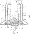
FIG. 2 is a sectional view showing one of the couplers at the time of separating the couplers from each other. -
FIG. 3 is an enlarged view of an essential part ofFIG. 2 . -
FIG. 4 is a sectional view of an essential part of a coupler according to a variation. -
FIG. 1 to FIG. 3 show an emergency release mechanism 1 for fluid loading equipment according to one embodiment of the present invention. The emergency release mechanism 1 includes a pair ofcouplers 11, which are coupled to each other by aclamp 12 such that thecouplers 11 are separable from each other. Theclamp 12 is configured such that when force that causes thecouplers 11 to move relative to each other becomes excessively great, theclamp 12 automatically releases the coupling between thecouplers 11. - A cargo fluid herein is, for example, liquefied hydrogen whose temperature is extremely low. Alternatively, the cargo fluid may be a different low-temperature liquid, such as LNG, or may be low-temperature gas.
- Each
coupler 11 includes a couplermain part 2 and avalve body 4. The couplermain part 2 has a vacuum double-pipe structure. Thevalve body 4 is disposed in the couplermain part 2 such that thevalve body 4 is movable in the axial direction of the couplermain part 2. Eachcoupler 11 further includes anannular valve seat 3, which is provided inside the distal end of the couplermain part 2. Thevalve seat 3 forms anopening 30, through which the cargo fluid flows. Hereinafter, for the sake of convenience of the description, the distal end side in the axial direction of the couplermain part 2 may be referred to as "forward", and the proximal end side, i.e., the opposite side, in the axial direction of the couplermain part 2 may be referred to as "backward". - Specifically, the coupler
main part 2 includes aninner pipe 21 and anouter pipe 23, between which a vacuum space is formed. The distal end of theinner pipe 21 is provided with aflange 22, which protrudes radially outward and radially inward. The distal end of theouter pipe 23 is provided with an expandeddiameter portion 24, and theclamp 12 is engaged with the expandeddiameter portion 24. The front end of theflange 22 of theinner pipe 21 and the front end of the expandeddiameter portion 24 of theouter pipe 23 are connected to each other by anannular end plate 25. - The
valve seat 3 includes atubular part 31 and aflange 32. Thetubular part 31 overlaps the inner peripheral surface of theflange 22 of theinner pipe 21. Theflange 32 overlaps the distal end surface of theflange 22. The inner peripheral surface of thetubular part 31 forms theaforementioned opening 30. Theflange 32 of thevalve seat 3 is fixed to theflange 22 of theinner pipe 21 by a plurality of bolts B1 (seeFIG. 2 ; the illustration of the bolts B1 is omitted inFIG. 1 ). - In the present embodiment, the
valve body 4 is urged toward thevalve seat 3 by two compression coil springs 9. Alternatively, the number ofsprings 9 may be one, or three or more. Back of thevalve body 4, anannular support 26 is provided on theinner pipe 21, and thesprings 9 are interposed between thesupport 26 and thevalve body 4. - The
valve body 4 is configured such that, at the time of separating thecouplers 11 from each other, as shown inFIG. 2 , in eachcoupler 11, thevalve body 4 is brought into contact with thevalve seat 3 by the urging force of thesprings 9 so as to close theopening 30, whereas at the time of coupling thecouplers 11 to each other, as shown inFIG. 1 , thevalve body 4 of eachcoupler 11 is pressed by thevalve body 4 of theother coupler 11 so as to move away from thevalve seat 3 and open theopening 30. When thevalve body 4 is in contact with thevalve seat 3, thevalve body 4 fits in theopening 30. - A
short tube 41 is mounted to thevalve body 4 in a manner to surround the forward portion of thesprings 9. Although not illustrated, theshort tube 41 is provided with a large number of through-holes, through which the cargo fluid passes. Theinner pipe 21 is provided with twoguides 27, which guide theshort tube 41. The two guides 27 are provided at respective positions that are away from each other in the axial direction of theinner pipe 21. Each of theguides 27 may be an annular guide that is continuous in the circumferential direction and provided with a large number of through-holes, or may be constituted by a plurality of pieces that are scattered in the circumferential direction. - More specifically, as shown in
FIG. 2 andFIG. 3 , thevalve body 4 includes a holdingmember 5, ablock 7, and an operatingmember 8. The holdingmember 5 holds at least one sealingmaterial 6. Theblock 7 and the operatingmember 8 are mounted to the holdingmember 5. - When the
valve body 4 is in contact with thevalve seat 3, the sealingmaterial 6 seals between thevalve body 4 and thevalve seat 3. In the present embodiment, three sealingmaterials 6 having different diameters from each other are disposed side by side in the axial direction of the couplermain part 2. The diameters of therespective sealing materials 6 increase backward from thefrontmost sealing material 6 to thebackmost sealing material 6. In accordance therewith, the inner peripheral surface of thevalve seat 3 is formed in a stepped manner, such that the diameter of the inner peripheral surface increases backward. Alternatively, the number of sealingmaterials 6 may be one or two. - The holding
member 5 is divided into three pieces, i.e., first tothird pieces 51 to 53, disposed side by side in the axial direction of the couplermain part 2. The backmostfirst piece 51 holds the sealingmaterial 6 having the greatest diameter. Thefirst piece 51 is provided with ashoulder portion 54, which comes into contact with thevalve seat 3. Also, the aforementionedshort tube 41 is mounted to thefirst piece 51. - The middle
second piece 52 holds themiddle sealing material 6, and is fixed to thefirst piece 51 by a plurality of bolts B2 (FIG. 3 shows only one of the bolts B2; the illustration of the bolts B2 is omitted inFIGS. 1 and2 ). The frontmostthird piece 53 holds the sealingmaterial 6 having the smallest diameter. Thethird piece 53 is fixed to thefirst piece 51 by a plurality of bolts B3 (FIG. 3 shows only one of the bolts B3; the illustration of the bolts B3 is omitted inFIGS. 1 and2 ). Thethird piece 53 is provided with a plurality ofscrew holes 53a for fixing the operatingmember 8. - The
block 7 covers the distal end surface of the holding member 5 (the surface positioned inside the sealingmaterials 6 and facing forward). Theblock 7 is made of a resin. Desirably, the resin of which theblock 7 is made has low thermal conductivity. - The operating
member 8 accommodating theblock 7 protrudes from the holdingmember 5 in a manner to pass through theopening 30. The operatingmember 8 is made of a metal. For example, the metal of which the operatingmember 8 is made is a copper alloy. - To be more specific, the operating
member 8 includes adome 81 and arod 84. Thedome 81 accommodates theblock 7. Therod 84 extends from thedome 81 along the center line of the couplermain part 2. Thedome 81 is fixed to the holdingmember 5 by using a plurality of bolts B4 (FIG. 3 shows only one of the bolts B4; the illustration of the bolts B4 is omitted inFIGS. 1 and2 ). - In the present embodiment, each bolt B4 is a bolt with threads formed on both ends thereof. One thread of each bolt B4 is screwed with a corresponding one of the
screw holes 53a formed in thethird piece 53 of the holdingmember 5, and the other thread of each bolt B4 is screwed with a corresponding one of nuts N. That is, in the present embodiment, thedome 81 is fixed to the holdingmember 5 by the bolts B4 and the nuts N. - As shown in
FIG. 3 , thedome 81 includes aperipheral wall 82 and aceiling wall 83. Theperipheral wall 82 surrounds theblock 7. Theceiling wall 83 faces the holdingmember 5, with theblock 7 being positioned between theceiling wall 83 and the holdingmember 5. Theperipheral wall 82 includes a straight portion and a tapered portion. The straight portion extends forward from the holdingmember 5. The tapered portion has a diameter that decreases from the front end of the straight portion. The peripheral edge of theceiling wall 83 is connected to the front end of the tapered portion. In the present embodiment, the wall thickness of the straight portion is less than or equal to the half of the wall thickness of the tapered portion. - A plurality of
sleeves 71 are interposed between theceiling wall 83 and the holdingmember 5. The plurality of bolts B4 are inserted through the plurality ofsleeves 71, respectively. The bolts B4 and thesleeves 71 are made of, for example, stainless steel. - As described above, in the emergency release mechanism 1 of the present embodiment, at the time of separating the
couplers 11 from each other, even though the operatingmember 8 of thevalve body 4 of eachcoupler 11 becomes exposed to the atmosphere through theopening 30, since the operatingmember 8 is made of a metal, the surface of the operatingmember 8 can be prevented from being charged with static electricity. In addition, thermal transfer between the holdingmember 5 and the operatingmember 8 is suppressed since the operatingmember 8 accommodates theresin block 7, which covers the distal end surface of the holdingmember 5. Accordingly, even if the temperature of the cargo fluid is extremely low, such as liquefied hydrogen, liquefaction of oxygen around the operatingmember 8 of thevalve body 4 can be suppressed. Even if liquid oxygen is generated on the surface of the operatingmember 8, the liquid oxygen is prevented from coming into direct contact with the flammable resin, of which theblock 7 is made. - The present invention is not limited to the above-described embodiment. Various modifications can be made without departing from the scope of the present invention.
- For example, each of the bolts B4 used for fixing the
dome 81 of the operatingmember 8 to the holdingmember 5 need not be a bolt with threads formed on both ends thereof. For example, as shown inFIG. 4 , the bolts B4 may each be a headed bolt, and such bolts B5 may be used to fix thedome 81 to the holdingmember 5. - Instead of using the
sleeves 71 shown inFIG. 3 , theperipheral wall 82 of thedome 81 of the operatingmember 8 may include a thick straight portion as shown inFIG. 4 . However, in a case where thesleeves 71 are used as in the above-described embodiment, fastening force that is applied when the bolts B4 are used can be received by thesleeves 71. Therefore, in this case, theperipheral wall 82 of thedome 81 of the operatingmember 8 can be made thin. This makes it possible to further suppress the thermal transfer between the holdingmember 5 and the operatingmember 8. -
- 1
- emergency release mechanism
- 11
- coupler
- 12
- clamp
- 2
- coupler main part
- 3
- valve seat
- 30
- opening
- 4
- valve body
- 5
- holding member
- 6
- sealing material
- 7
- block
- 71
- sleeve
- 8
- operating member
- 81
- dome
- 82
- peripheral wall
- 83
- ceiling wall
- 84
- rod
- 9
- spring
- B1 to B4
- bolt
Claims (3)
- An emergency release mechanism for fluid loading equipment, the emergency release mechanism comprising a pair of couplers that are coupled to each other by a clamp such that the couplers are separable from each other, whereineach of the pair of couplers includes:a coupler main part with a vacuum double-pipe structure;a valve seat provided inside a distal end of the coupler main part, the valve seat forming an opening through which a cargo fluid flows;a valve body disposed in the coupler main part such that the valve body is movable in an axial direction of the coupler main part; anda spring that urges the valve body toward the valve seat,the valve body is configured such that,at a time of separating the couplers from each other, in each coupler, the valve body is brought into contact with the valve seat by urging force of the spring so as to close the opening, andat a time of coupling the couplers to each other, the valve body of each coupler is pressed by the valve body of the other coupler so as to move away from the valve seat and open the opening, andthe valve body includes:a holding member that holds a sealing material that seals between the valve body and the valve seat when the valve body is in contact with the valve seat;a block made of a resin, the block covering a distal end surface of the holding member; andan operating member made of a metal, the operating member accommodating the block and protruding from the holding member in a manner to pass through the opening.
- The emergency release mechanism for fluid loading equipment according to claim 1, whereinthe operating member includes:a dome that accommodates the block; anda rod that extends from the dome along a center line of the coupler main part, andthe dome is fixed to the holding member by using a plurality of bolts.
- The emergency release mechanism for fluid loading equipment according to claim 2, whereinthe dome includes:a peripheral wall that surrounds the block; anda ceiling wall that faces the holding member, with the block being positioned between the ceiling wall and the holding member,a plurality of sleeves are interposed between the ceiling wall and the holding member, andthe plurality of bolts are inserted through the plurality of sleeves, respectively.
Applications Claiming Priority (2)
| Application Number | Priority Date | Filing Date | Title |
|---|---|---|---|
| JP2018204418A JP7245025B2 (en) | 2018-10-30 | 2018-10-30 | Emergency release mechanism for fluid handling equipment |
| PCT/JP2019/042155 WO2020090728A1 (en) | 2018-10-30 | 2019-10-28 | Emergency separation mechanism for fluid handling device |
Publications (3)
| Publication Number | Publication Date |
|---|---|
| EP3875827A1 true EP3875827A1 (en) | 2021-09-08 |
| EP3875827A4 EP3875827A4 (en) | 2022-07-27 |
| EP3875827B1 EP3875827B1 (en) | 2024-09-11 |
Family
ID=70464091
Family Applications (1)
| Application Number | Title | Priority Date | Filing Date |
|---|---|---|---|
| EP19879808.4A Active EP3875827B1 (en) | 2018-10-30 | 2019-10-28 | Emergency release mechanism for fluid loading equipment |
Country Status (9)
| Country | Link |
|---|---|
| US (1) | US11815212B2 (en) |
| EP (1) | EP3875827B1 (en) |
| JP (1) | JP7245025B2 (en) |
| KR (2) | KR102626815B1 (en) |
| CN (1) | CN113330241B (en) |
| AU (1) | AU2019369689B2 (en) |
| DK (1) | DK3875827T3 (en) |
| RU (1) | RU2769212C1 (en) |
| WO (1) | WO2020090728A1 (en) |
Cited By (1)
| Publication number | Priority date | Publication date | Assignee | Title |
|---|---|---|---|---|
| FR3119005A1 (en) * | 2021-01-19 | 2022-07-22 | L'air Liquide, Societe Anonyme Pour L'etude Et L'exploitation Des Procedes Georges Claude | Emergency coupling and detachment device |
Families Citing this family (4)
| Publication number | Priority date | Publication date | Assignee | Title |
|---|---|---|---|---|
| FR3119007B1 (en) * | 2021-01-19 | 2023-02-24 | Air Liquide | Emergency coupling and detachment device |
| FR3128760A1 (en) * | 2021-10-28 | 2023-05-05 | Airbus | OPTIMIZED CONNECTION ASSEMBLY BETWEEN TWO PORTIONS OF A PIPELINE FOR THE TRANSPORT OF A CRYOGENIC FLUID, COMPRISING AN ADDITIONAL THERMAL INSULATION CHAMBER AND A FLUID EXPANSION CHAMBER. |
| FR3131949B1 (en) * | 2022-01-17 | 2023-12-08 | Air Liquide | Coupling device and its purging process |
| KR102965282B1 (en) * | 2023-08-30 | 2026-05-13 | 롯데케미칼 주식회사 | Adapter device for pressure test of pressure vessels |
Family Cites Families (24)
| Publication number | Priority date | Publication date | Assignee | Title |
|---|---|---|---|---|
| US2393489A (en) * | 1944-08-26 | 1946-01-22 | Bendix Aviat Corp | Fluid coupling |
| US3367366A (en) * | 1965-10-11 | 1968-02-06 | Universal Oil Prod Co | Disconnect with minimum inclusion |
| FR2509003B1 (en) * | 1981-07-01 | 1985-07-05 | Cefilac | GASKET FOR HIGH OR LOW TEMPERATURES IN STATIC OR DYNAMIC CONDITIONS |
| JPS58178087A (en) * | 1982-04-13 | 1983-10-18 | 株式会社新潟鐵工所 | Emergency separator for fluid cargo-handling line |
| JPS58130193U (en) * | 1982-02-26 | 1983-09-02 | 株式会社新潟鐵工所 | Emergency disconnection device for fluid handling lines |
| US4512369A (en) * | 1982-02-26 | 1985-04-23 | Niigata Engineering Co., Ltd. | Emergency disconnector for fluid loading and unloading lines |
| US4685490A (en) * | 1983-01-19 | 1987-08-11 | Swagelok Company | Coupling |
| US4709725A (en) * | 1987-02-17 | 1987-12-01 | Vetco Gray, Inc. | Metal-to-metal seal structure |
| JPH1137317A (en) * | 1997-07-16 | 1999-02-12 | Hideo Koo | Ball valve |
| JP4531934B2 (en) * | 2000-06-12 | 2010-08-25 | サーパス工業株式会社 | Connecting device |
| US8020576B2 (en) * | 2006-10-26 | 2011-09-20 | Delaware Capital Formation, Inc. | Emergency shutoff valve for use in a fuel dispensing system |
| JP4948970B2 (en) | 2006-10-31 | 2012-06-06 | 大阪サニタリー金属工業協同組合 | Valve devices and fittings |
| KR200456403Y1 (en) * | 2009-04-09 | 2011-10-28 | 송용석 | Anchor bolt |
| KR102023799B1 (en) * | 2012-10-05 | 2019-09-20 | 시케이디 가부시키가이샤 | Capacitive displacement sensor |
| CN203098929U (en) * | 2012-12-31 | 2013-07-31 | 宣达实业集团浙江质一阀门制造有限公司 | Ball valve for compressed natural gas tank truck |
| CN104864208A (en) * | 2015-04-17 | 2015-08-26 | 柳州市乾阳机电设备有限公司 | Quick connector capable of automatically opening and closing interface |
| JP6396263B2 (en) | 2015-07-10 | 2018-09-26 | 東京貿易エンジニアリング株式会社 | Emergency release device for fluid handling equipment |
| JP6554746B2 (en) | 2015-07-24 | 2019-08-07 | 国立大学法人京都工芸繊維大学 | Screening method for microorganisms capable of producing vinyl compounds |
| KR20170020584A (en) | 2015-08-12 | 2017-02-23 | (주)태성공업 | Pin assembling device for boom of construction equipment |
| US10436363B2 (en) * | 2016-03-25 | 2019-10-08 | Opw-Engineered Systems, Inc. | Swivel joint with electrical conductivity grease fitting |
| JP6685246B2 (en) | 2017-02-10 | 2020-04-22 | 東京貿易エンジニアリング株式会社 | Emergency release mechanism for fluid handling equipment |
| JP6901873B2 (en) | 2017-03-03 | 2021-07-14 | サーパス工業株式会社 | Fluid equipment |
| CN206874871U (en) * | 2017-06-01 | 2018-01-12 | 宁波埃美柯铜阀门有限公司 | Antistatic fire-retardant ball valve |
| CN207921562U (en) * | 2017-11-15 | 2018-09-28 | 沈阳航天新光集团有限公司 | A kind of fluid path connection separator |
-
2018
- 2018-10-30 JP JP2018204418A patent/JP7245025B2/en active Active
-
2019
- 2019-10-28 AU AU2019369689A patent/AU2019369689B2/en active Active
- 2019-10-28 WO PCT/JP2019/042155 patent/WO2020090728A1/en not_active Ceased
- 2019-10-28 DK DK19879808.4T patent/DK3875827T3/en active
- 2019-10-28 KR KR1020217012668A patent/KR102626815B1/en active Active
- 2019-10-28 KR KR1020237027000A patent/KR20230124094A/en not_active Withdrawn
- 2019-10-28 EP EP19879808.4A patent/EP3875827B1/en active Active
- 2019-10-28 US US17/289,780 patent/US11815212B2/en active Active
- 2019-10-28 RU RU2021115274A patent/RU2769212C1/en active
- 2019-10-28 CN CN201980072516.8A patent/CN113330241B/en active Active
Cited By (2)
| Publication number | Priority date | Publication date | Assignee | Title |
|---|---|---|---|---|
| FR3119005A1 (en) * | 2021-01-19 | 2022-07-22 | L'air Liquide, Societe Anonyme Pour L'etude Et L'exploitation Des Procedes Georges Claude | Emergency coupling and detachment device |
| WO2022157043A1 (en) * | 2021-01-19 | 2022-07-28 | L'air Liquide, Societe Anonyme Pour L'etude Et L'exploitation Des Procedes Georges Claude | Emergency coupling and release device |
Also Published As
| Publication number | Publication date |
|---|---|
| JP2020070849A (en) | 2020-05-07 |
| AU2019369689B2 (en) | 2023-02-02 |
| CN113330241B (en) | 2023-01-10 |
| EP3875827B1 (en) | 2024-09-11 |
| KR20210058974A (en) | 2021-05-24 |
| KR20230124094A (en) | 2023-08-24 |
| RU2769212C1 (en) | 2022-03-29 |
| DK3875827T3 (en) | 2024-09-30 |
| AU2019369689A1 (en) | 2021-06-03 |
| US20210396338A1 (en) | 2021-12-23 |
| US11815212B2 (en) | 2023-11-14 |
| JP7245025B2 (en) | 2023-03-23 |
| WO2020090728A1 (en) | 2020-05-07 |
| EP3875827A4 (en) | 2022-07-27 |
| KR102626815B1 (en) | 2024-01-18 |
| CN113330241A (en) | 2021-08-31 |
Similar Documents
| Publication | Publication Date | Title |
|---|---|---|
| EP3875827B1 (en) | Emergency release mechanism for fluid loading equipment | |
| US11525538B2 (en) | Quick-release Johnston coupling | |
| US2995388A (en) | Gripping device | |
| EP3734131A1 (en) | Loading arm connector and loading arm | |
| US8267433B2 (en) | Plug-in coupling for cryogenic lines | |
| US6546947B2 (en) | Safety system for fluid conduit | |
| EP2538123A1 (en) | Coupling for fluid | |
| US4481778A (en) | Thermally disconnecting passive parallel orbital supports | |
| EP3916284A1 (en) | Quick connector locking structure for air brake system pipeline of commercial vehicle | |
| US6260569B1 (en) | Safety system for fluid conduit | |
| US11608923B2 (en) | Fluid loading joint | |
| US10801674B2 (en) | Retention system for gas cylinder valve | |
| JP5444542B2 (en) | Emergency shut-off device for lubrication equipment | |
| US20110215564A1 (en) | Three Bolt Breakaway Coupling | |
| KR20230111612A (en) | Method for creating a connection, and connection device | |
| KR102415368B1 (en) | Hydraulic emergency release coupling | |
| US20200271259A1 (en) | Safety System for High Pressure Conduits | |
| US3617075A (en) | Quick disconnect coupling seal | |
| EP4530514A1 (en) | Coupling assembly and fluid line connection | |
| US20220212535A1 (en) | Device for fastening a pressurized gas tank to a frame | |
| RU2813001C1 (en) | Emergency release coupling | |
| AU2026201600A1 (en) | Emergency release mechanism of fluid loading equipment | |
| KR20260040291A (en) | Separation valve for cryogenic fluid tanks | |
| CN121461152A (en) | Overvoltage release device for a switching device | |
| JP2022135108A (en) | pressure vessel |
Legal Events
| Date | Code | Title | Description |
|---|---|---|---|
| STAA | Information on the status of an ep patent application or granted ep patent |
Free format text: STATUS: THE INTERNATIONAL PUBLICATION HAS BEEN MADE |
|
| PUAI | Public reference made under article 153(3) epc to a published international application that has entered the european phase |
Free format text: ORIGINAL CODE: 0009012 |
|
| STAA | Information on the status of an ep patent application or granted ep patent |
Free format text: STATUS: REQUEST FOR EXAMINATION WAS MADE |
|
| 17P | Request for examination filed |
Effective date: 20210309 |
|
| AK | Designated contracting states |
Kind code of ref document: A1 Designated state(s): AL AT BE BG CH CY CZ DE DK EE ES FI FR GB GR HR HU IE IS IT LI LT LU LV MC MK MT NL NO PL PT RO RS SE SI SK SM TR |
|
| DAV | Request for validation of the european patent (deleted) | ||
| DAX | Request for extension of the european patent (deleted) | ||
| A4 | Supplementary search report drawn up and despatched |
Effective date: 20220629 |
|
| RIC1 | Information provided on ipc code assigned before grant |
Ipc: F16L 29/04 20060101ALI20220623BHEP Ipc: F16L 59/18 20060101ALI20220623BHEP Ipc: F16L 37/32 20060101ALI20220623BHEP Ipc: F16L 23/12 20060101ALI20220623BHEP Ipc: B67D 7/32 20100101ALI20220623BHEP Ipc: B67D 9/00 20100101ALI20220623BHEP Ipc: F16L 37/30 20060101AFI20220623BHEP |
|
| GRAP | Despatch of communication of intention to grant a patent |
Free format text: ORIGINAL CODE: EPIDOSNIGR1 |
|
| STAA | Information on the status of an ep patent application or granted ep patent |
Free format text: STATUS: GRANT OF PATENT IS INTENDED |
|
| INTG | Intention to grant announced |
Effective date: 20240604 |
|
| RIN1 | Information on inventor provided before grant (corrected) |
Inventor name: KAWAI, TSUTOMU Inventor name: OKUMURA, KENTARO Inventor name: UNNO, SHUNTARO Inventor name: UMEMURA, TOMOAKI |
|
| GRAS | Grant fee paid |
Free format text: ORIGINAL CODE: EPIDOSNIGR3 |
|
| GRAA | (expected) grant |
Free format text: ORIGINAL CODE: 0009210 |
|
| STAA | Information on the status of an ep patent application or granted ep patent |
Free format text: STATUS: THE PATENT HAS BEEN GRANTED |
|
| AK | Designated contracting states |
Kind code of ref document: B1 Designated state(s): AL AT BE BG CH CY CZ DE DK EE ES FI FR GB GR HR HU IE IS IT LI LT LU LV MC MK MT NL NO PL PT RO RS SE SI SK SM TR |
|
| REG | Reference to a national code |
Ref country code: GB Ref legal event code: FG4D |
|
| REG | Reference to a national code |
Ref country code: CH Ref legal event code: EP |
|
| REG | Reference to a national code |
Ref country code: DE Ref legal event code: R096 Ref document number: 602019058897 Country of ref document: DE |
|
| REG | Reference to a national code |
Ref country code: DK Ref legal event code: T3 Effective date: 20240925 |
|
| REG | Reference to a national code |
Ref country code: SE Ref legal event code: TRGR |
|
| REG | Reference to a national code |
Ref country code: NL Ref legal event code: FP Ref country code: IE Ref legal event code: FG4D |
|
| REG | Reference to a national code |
Ref country code: LT Ref legal event code: MG9D |
|
| PG25 | Lapsed in a contracting state [announced via postgrant information from national office to epo] |
Ref country code: GR Free format text: LAPSE BECAUSE OF FAILURE TO SUBMIT A TRANSLATION OF THE DESCRIPTION OR TO PAY THE FEE WITHIN THE PRESCRIBED TIME-LIMIT Effective date: 20241212 Ref country code: FI Free format text: LAPSE BECAUSE OF FAILURE TO SUBMIT A TRANSLATION OF THE DESCRIPTION OR TO PAY THE FEE WITHIN THE PRESCRIBED TIME-LIMIT Effective date: 20240911 |
|
| PG25 | Lapsed in a contracting state [announced via postgrant information from national office to epo] |
Ref country code: BG Free format text: LAPSE BECAUSE OF FAILURE TO SUBMIT A TRANSLATION OF THE DESCRIPTION OR TO PAY THE FEE WITHIN THE PRESCRIBED TIME-LIMIT Effective date: 20240911 |
|
| PG25 | Lapsed in a contracting state [announced via postgrant information from national office to epo] |
Ref country code: LV Free format text: LAPSE BECAUSE OF FAILURE TO SUBMIT A TRANSLATION OF THE DESCRIPTION OR TO PAY THE FEE WITHIN THE PRESCRIBED TIME-LIMIT Effective date: 20240911 |
|
| PG25 | Lapsed in a contracting state [announced via postgrant information from national office to epo] |
Ref country code: HR Free format text: LAPSE BECAUSE OF FAILURE TO SUBMIT A TRANSLATION OF THE DESCRIPTION OR TO PAY THE FEE WITHIN THE PRESCRIBED TIME-LIMIT Effective date: 20240911 |
|
| PG25 | Lapsed in a contracting state [announced via postgrant information from national office to epo] |
Ref country code: RS Free format text: LAPSE BECAUSE OF FAILURE TO SUBMIT A TRANSLATION OF THE DESCRIPTION OR TO PAY THE FEE WITHIN THE PRESCRIBED TIME-LIMIT Effective date: 20241211 Ref country code: ES Free format text: LAPSE BECAUSE OF FAILURE TO SUBMIT A TRANSLATION OF THE DESCRIPTION OR TO PAY THE FEE WITHIN THE PRESCRIBED TIME-LIMIT Effective date: 20240911 |
|
| PG25 | Lapsed in a contracting state [announced via postgrant information from national office to epo] |
Ref country code: RS Free format text: LAPSE BECAUSE OF FAILURE TO SUBMIT A TRANSLATION OF THE DESCRIPTION OR TO PAY THE FEE WITHIN THE PRESCRIBED TIME-LIMIT Effective date: 20241211 Ref country code: LV Free format text: LAPSE BECAUSE OF FAILURE TO SUBMIT A TRANSLATION OF THE DESCRIPTION OR TO PAY THE FEE WITHIN THE PRESCRIBED TIME-LIMIT Effective date: 20240911 Ref country code: HR Free format text: LAPSE BECAUSE OF FAILURE TO SUBMIT A TRANSLATION OF THE DESCRIPTION OR TO PAY THE FEE WITHIN THE PRESCRIBED TIME-LIMIT Effective date: 20240911 Ref country code: GR Free format text: LAPSE BECAUSE OF FAILURE TO SUBMIT A TRANSLATION OF THE DESCRIPTION OR TO PAY THE FEE WITHIN THE PRESCRIBED TIME-LIMIT Effective date: 20241212 Ref country code: FI Free format text: LAPSE BECAUSE OF FAILURE TO SUBMIT A TRANSLATION OF THE DESCRIPTION OR TO PAY THE FEE WITHIN THE PRESCRIBED TIME-LIMIT Effective date: 20240911 Ref country code: ES Free format text: LAPSE BECAUSE OF FAILURE TO SUBMIT A TRANSLATION OF THE DESCRIPTION OR TO PAY THE FEE WITHIN THE PRESCRIBED TIME-LIMIT Effective date: 20240911 Ref country code: BG Free format text: LAPSE BECAUSE OF FAILURE TO SUBMIT A TRANSLATION OF THE DESCRIPTION OR TO PAY THE FEE WITHIN THE PRESCRIBED TIME-LIMIT Effective date: 20240911 |
|
| REG | Reference to a national code |
Ref country code: AT Ref legal event code: MK05 Ref document number: 1722972 Country of ref document: AT Kind code of ref document: T Effective date: 20240911 |
|
| PG25 | Lapsed in a contracting state [announced via postgrant information from national office to epo] |
Ref country code: PT Free format text: LAPSE BECAUSE OF FAILURE TO SUBMIT A TRANSLATION OF THE DESCRIPTION OR TO PAY THE FEE WITHIN THE PRESCRIBED TIME-LIMIT Effective date: 20250113 Ref country code: IS Free format text: LAPSE BECAUSE OF FAILURE TO SUBMIT A TRANSLATION OF THE DESCRIPTION OR TO PAY THE FEE WITHIN THE PRESCRIBED TIME-LIMIT Effective date: 20250111 |
|
| PG25 | Lapsed in a contracting state [announced via postgrant information from national office to epo] |
Ref country code: RO Free format text: LAPSE BECAUSE OF FAILURE TO SUBMIT A TRANSLATION OF THE DESCRIPTION OR TO PAY THE FEE WITHIN THE PRESCRIBED TIME-LIMIT Effective date: 20240911 Ref country code: SM Free format text: LAPSE BECAUSE OF FAILURE TO SUBMIT A TRANSLATION OF THE DESCRIPTION OR TO PAY THE FEE WITHIN THE PRESCRIBED TIME-LIMIT Effective date: 20240911 |
|
| PG25 | Lapsed in a contracting state [announced via postgrant information from national office to epo] |
Ref country code: EE Free format text: LAPSE BECAUSE OF FAILURE TO SUBMIT A TRANSLATION OF THE DESCRIPTION OR TO PAY THE FEE WITHIN THE PRESCRIBED TIME-LIMIT Effective date: 20240911 Ref country code: AT Free format text: LAPSE BECAUSE OF FAILURE TO SUBMIT A TRANSLATION OF THE DESCRIPTION OR TO PAY THE FEE WITHIN THE PRESCRIBED TIME-LIMIT Effective date: 20240911 |
|
| PG25 | Lapsed in a contracting state [announced via postgrant information from national office to epo] |
Ref country code: CZ Free format text: LAPSE BECAUSE OF FAILURE TO SUBMIT A TRANSLATION OF THE DESCRIPTION OR TO PAY THE FEE WITHIN THE PRESCRIBED TIME-LIMIT Effective date: 20240911 Ref country code: PL Free format text: LAPSE BECAUSE OF FAILURE TO SUBMIT A TRANSLATION OF THE DESCRIPTION OR TO PAY THE FEE WITHIN THE PRESCRIBED TIME-LIMIT Effective date: 20240911 |
|
| PG25 | Lapsed in a contracting state [announced via postgrant information from national office to epo] |
Ref country code: SK Free format text: LAPSE BECAUSE OF FAILURE TO SUBMIT A TRANSLATION OF THE DESCRIPTION OR TO PAY THE FEE WITHIN THE PRESCRIBED TIME-LIMIT Effective date: 20240911 |
|
| REG | Reference to a national code |
Ref country code: CH Ref legal event code: PL |
|
| REG | Reference to a national code |
Ref country code: DE Ref legal event code: R097 Ref document number: 602019058897 Country of ref document: DE |
|
| PG25 | Lapsed in a contracting state [announced via postgrant information from national office to epo] |
Ref country code: MC Free format text: LAPSE BECAUSE OF FAILURE TO SUBMIT A TRANSLATION OF THE DESCRIPTION OR TO PAY THE FEE WITHIN THE PRESCRIBED TIME-LIMIT Effective date: 20240911 |
|
| PG25 | Lapsed in a contracting state [announced via postgrant information from national office to epo] |
Ref country code: LU Free format text: LAPSE BECAUSE OF NON-PAYMENT OF DUE FEES Effective date: 20241028 |
|
| PLBE | No opposition filed within time limit |
Free format text: ORIGINAL CODE: 0009261 |
|
| STAA | Information on the status of an ep patent application or granted ep patent |
Free format text: STATUS: NO OPPOSITION FILED WITHIN TIME LIMIT |
|
| PG25 | Lapsed in a contracting state [announced via postgrant information from national office to epo] |
Ref country code: CH Free format text: LAPSE BECAUSE OF NON-PAYMENT OF DUE FEES Effective date: 20241031 |
|
| 26N | No opposition filed |
Effective date: 20250612 |
|
| PGFP | Annual fee paid to national office [announced via postgrant information from national office to epo] |
Ref country code: NL Payment date: 20250912 Year of fee payment: 7 Ref country code: IT Payment date: 20250922 Year of fee payment: 7 |
|
| PGFP | Annual fee paid to national office [announced via postgrant information from national office to epo] |
Ref country code: BE Payment date: 20250917 Year of fee payment: 7 Ref country code: GB Payment date: 20250904 Year of fee payment: 7 |
|
| PGFP | Annual fee paid to national office [announced via postgrant information from national office to epo] |
Ref country code: FR Payment date: 20250908 Year of fee payment: 7 |
|
| PGFP | Annual fee paid to national office [announced via postgrant information from national office to epo] |
Ref country code: SE Payment date: 20250910 Year of fee payment: 7 |
|
| PG25 | Lapsed in a contracting state [announced via postgrant information from national office to epo] |
Ref country code: IE Free format text: LAPSE BECAUSE OF NON-PAYMENT OF DUE FEES Effective date: 20241028 |
|
| PGFP | Annual fee paid to national office [announced via postgrant information from national office to epo] |
Ref country code: DE Payment date: 20250902 Year of fee payment: 7 |
|
| PGFP | Annual fee paid to national office [announced via postgrant information from national office to epo] |
Ref country code: NO Payment date: 20251009 Year of fee payment: 7 |
|
| PGFP | Annual fee paid to national office [announced via postgrant information from national office to epo] |
Ref country code: DK Payment date: 20251014 Year of fee payment: 7 |
|
| PG25 | Lapsed in a contracting state [announced via postgrant information from national office to epo] |
Ref country code: HU Free format text: LAPSE BECAUSE OF FAILURE TO SUBMIT A TRANSLATION OF THE DESCRIPTION OR TO PAY THE FEE WITHIN THE PRESCRIBED TIME-LIMIT; INVALID AB INITIO Effective date: 20191028 |
|
| PG25 | Lapsed in a contracting state [announced via postgrant information from national office to epo] |
Ref country code: CY Free format text: LAPSE BECAUSE OF FAILURE TO SUBMIT A TRANSLATION OF THE DESCRIPTION OR TO PAY THE FEE WITHIN THE PRESCRIBED TIME-LIMIT; INVALID AB INITIO Effective date: 20191028 |
|
| PG25 | Lapsed in a contracting state [announced via postgrant information from national office to epo] |
Ref country code: TR Free format text: LAPSE BECAUSE OF FAILURE TO SUBMIT A TRANSLATION OF THE DESCRIPTION OR TO PAY THE FEE WITHIN THE PRESCRIBED TIME-LIMIT Effective date: 20240911 |
|
| PG25 | Lapsed in a contracting state [announced via postgrant information from national office to epo] |
Ref country code: SI Free format text: LAPSE BECAUSE OF FAILURE TO SUBMIT A TRANSLATION OF THE DESCRIPTION OR TO PAY THE FEE WITHIN THE PRESCRIBED TIME-LIMIT Effective date: 20240911 |
|
| PG25 | Lapsed in a contracting state [announced via postgrant information from national office to epo] |
Ref country code: LT Free format text: LAPSE BECAUSE OF FAILURE TO SUBMIT A TRANSLATION OF THE DESCRIPTION OR TO PAY THE FEE WITHIN THE PRESCRIBED TIME-LIMIT Effective date: 20240911 |