EP3875775A1 - Electric fluid machine with two-part structural casing - Google Patents
Electric fluid machine with two-part structural casing Download PDFInfo
- Publication number
- EP3875775A1 EP3875775A1 EP21156153.5A EP21156153A EP3875775A1 EP 3875775 A1 EP3875775 A1 EP 3875775A1 EP 21156153 A EP21156153 A EP 21156153A EP 3875775 A1 EP3875775 A1 EP 3875775A1
- Authority
- EP
- European Patent Office
- Prior art keywords
- housing
- turbo machine
- shaft
- bearing
- rotation
- Prior art date
- Legal status (The legal status is an assumption and is not a legal conclusion. Google has not performed a legal analysis and makes no representation as to the accuracy of the status listed.)
- Withdrawn
Links
Images

Classifications
-
- F—MECHANICAL ENGINEERING; LIGHTING; HEATING; WEAPONS; BLASTING
- F04—POSITIVE - DISPLACEMENT MACHINES FOR LIQUIDS; PUMPS FOR LIQUIDS OR ELASTIC FLUIDS
- F04D—NON-POSITIVE-DISPLACEMENT PUMPS
- F04D25/00—Pumping installations or systems
- F04D25/02—Units comprising pumps and their driving means
- F04D25/06—Units comprising pumps and their driving means the pump being electrically driven
-
- F—MECHANICAL ENGINEERING; LIGHTING; HEATING; WEAPONS; BLASTING
- F04—POSITIVE - DISPLACEMENT MACHINES FOR LIQUIDS; PUMPS FOR LIQUIDS OR ELASTIC FLUIDS
- F04D—NON-POSITIVE-DISPLACEMENT PUMPS
- F04D29/00—Details, component parts, or accessories
- F04D29/05—Shafts or bearings, or assemblies thereof, specially adapted for elastic fluid pumps
- F04D29/056—Bearings
-
- F—MECHANICAL ENGINEERING; LIGHTING; HEATING; WEAPONS; BLASTING
- F04—POSITIVE - DISPLACEMENT MACHINES FOR LIQUIDS; PUMPS FOR LIQUIDS OR ELASTIC FLUIDS
- F04D—NON-POSITIVE-DISPLACEMENT PUMPS
- F04D29/00—Details, component parts, or accessories
- F04D29/40—Casings; Connections of working fluid
- F04D29/42—Casings; Connections of working fluid for radial or helico-centrifugal pumps
- F04D29/4206—Casings; Connections of working fluid for radial or helico-centrifugal pumps especially adapted for elastic fluid pumps
- F04D29/4226—Fan casings
- F04D29/4253—Fan casings with axial entry and discharge
-
- F—MECHANICAL ENGINEERING; LIGHTING; HEATING; WEAPONS; BLASTING
- F04—POSITIVE - DISPLACEMENT MACHINES FOR LIQUIDS; PUMPS FOR LIQUIDS OR ELASTIC FLUIDS
- F04D—NON-POSITIVE-DISPLACEMENT PUMPS
- F04D29/00—Details, component parts, or accessories
- F04D29/40—Casings; Connections of working fluid
- F04D29/42—Casings; Connections of working fluid for radial or helico-centrifugal pumps
- F04D29/44—Fluid-guiding means, e.g. diffusers
- F04D29/441—Fluid-guiding means, e.g. diffusers especially adapted for elastic fluid pumps
- F04D29/444—Bladed diffusers
-
- F—MECHANICAL ENGINEERING; LIGHTING; HEATING; WEAPONS; BLASTING
- F05—INDEXING SCHEMES RELATING TO ENGINES OR PUMPS IN VARIOUS SUBCLASSES OF CLASSES F01-F04
- F05D—INDEXING SCHEME FOR ASPECTS RELATING TO NON-POSITIVE-DISPLACEMENT MACHINES OR ENGINES, GAS-TURBINES OR JET-PROPULSION PLANTS
- F05D2250/00—Geometry
- F05D2250/50—Inlet or outlet
- F05D2250/52—Outlet
Definitions
- the invention relates to a turbo machine according to the preamble of claim 1 and a household or kitchen appliance with such a turbo machine according to claim 15.
- Fluid flow machines can be used, which usually suck in the fluid on a suction side by means of an impeller rotating in a housing and release it again on a pressure side.
- Fluid flow machines can also be referred to as fans, blowers or fans, for example for moving air, depending on the design and application.
- Such flow machines are also used in household and kitchen appliances for generating fluid flows.
- a vacuum cleaner by means of such an air flow, dirt particles and the like are sucked into the vacuum cleaner from a substrate, such as in particular from a floor, and passed through at least one filter.
- heated air is blown into the drum in order to dry the damp laundry located there and to remove the moisture from the drum with the air flow.
- hot air can be blown into the cooking space in order to cook the food there.
- this can be implemented in a steam cooker with hot and humid air.
- Such flow machines can also be used in household and kitchen appliances to generate a flow of liquid, e.g. for pumping out the washing liquor in a washing machine.
- the impeller of such a turbomachine is driven for this purpose and the impeller blades, due to their design and arrangement, ensure the desired movement of the fluid or the generation of the fluid flow.
- Electric motors which transmit their rotational movement to the impeller via a common shaft, are usually used to drive such turbomachines.
- the impeller can also be referred to as the output of the turbomachine.
- the electric motor is usually arranged in a stationary manner in the housing of the turbomachine and the shaft is guided through the electric motor. At one end, the shaft protrudes sufficiently far beyond the electric motor so that the impeller is arranged at this protruding end of the shaft. This end of the shaft can also be used as that of the electric motor facing away from the shaft end.
- the impeller is usually sufficiently enclosed by the housing of the turbomachine to suck in the fluid through at least one passage opening of the housing on the suction side and through at least one passage opening of the housing on the pressure side to the environment or to another component of a device such as a household appliance or of a kitchen appliance.
- the shaft is usually supported in two places by bearings such as roller bearings relative to the housing so that it can rotate around a longitudinal axis of the turbomachine as the axis of rotation.
- the two bearings are usually arranged on both sides of the electric motor in order to achieve a stable hold of the shaft with respect to the housing.
- the rotor of the electric motor is arranged on the shaft between the two bearings and positioned inside the stator of the electric motor.
- the outstanding shaft end facing away from the electric motor, which carries the impeller, extends from one of the two bearings away from the rotor and is unsupported.
- the disadvantage of such bearings in turbo machines is that the alignment of the shaft with respect to the stationary components of the turbo machine such as the housing, the outer rings of the two bearings and the stator of the electric motor depends on numerous manufacturing and assembly tolerances, which lead to a deviation and in particular to a Can lead to tilting of the shaft relative to the axis of rotation of the turbomachine. This can also be referred to as an alignment problem. This can lead to undesired contacts between stationary and rotatable components of the turbomachine, which block one another or at least rub one another and thereby damage one another. The radial air gap between the rotor and stator of the electric motor can also be widened or reduced as a result, which can impair the function of the electric motor. If there is contact between the rotor and stator of the electric motor, this can prevent the rotor from rotating and make the electric motor unusable.
- the bearing of the shaft of a turbo machine between the impeller and the rotor of the electric motor.
- the impeller not only the impeller but also the rotor is arranged at one end of the shaft which is opposite the impeller, as described above.
- the bearing is arranged in between and is usually designed, for example, as a self-contained cartridge chamber, which can simplify assembly and reduce tolerances.
- EP 2 401 516 B1 a rotor assembly including a shaft on which an impeller, a rotor core and a bearing insert are mounted, the bearing insert being mounted between the impeller and the rotor core and a pair of bearings, a spring that applies a preload to each of the bearings, and a sleeve surrounding the bearings. After installation in the turbomachine, the sleeve is used to hold the housing against it.
- the rotor assembly shaft is supported by two preloaded bearings.
- the bearings are ideally spaced a predetermined amount and the spring has a predetermined spring rate.
- the two bearings are preloaded with the same well-defined force.
- bearings or cartridge bearings for shafts are technically comparatively complex, which can lead to corresponding costs.
- the use and arrangement of a spring for generating the preload described above can lead to a comparatively high technical effort in terms of design and construction as well as in implementation and assembly.
- the use of a spring can also lead to additional material and assembly costs.
- the storage or the cartridge chamber is to be installed in the housing of the turbomachine as a further assembly step.
- the WO 2017/098203 A1 or the EP 3 387 741 A1 relates to an electric motor with a frame, with a rotor assembly comprising a magnet, a bearing assembly, an impeller and a shaft, and with a stator assembly comprising a stator core and a coil.
- the frame has an inner wall and an outer wall, the outer wall surrounding the inner wall and defining an annular channel between the inner wall and the outer wall.
- the frame also has diffuser vanes that extend from the inner wall to the outer wall through the annular channel.
- the inner wall defines a bore for supporting the rotor assembly and the outer wall defines a generally cylindrical outer housing of the motor.
- the frame with the inner wall, outer wall and intermediate diffuser blades is in one piece, that is to say formed from one piece, for example as an injection-molded part.
- the frame and, in particular, its diffuser blades are of comparatively simple design in order to enable them to be manufactured in one piece, e.g. as an injection-molded part, i.e. the frame and its diffuser blades extend in a straight line in the longitudinal direction of the electric motor in order to be able to be removed from the injection mold.
- a further disadvantage is that a cartridge bearing as described above is used as the bearing assembly, which brings with it the corresponding disadvantages such as, in particular, its comparatively high complexity and the associated comparatively high number of parts and high costs.
- These disadvantages of the rotor assembly of JP 5466040 B2 or the EP 2 401 516 B1 can thus by the electric motor of the WO 2017/098203 A1 or the EP 3 387 741 A1 cannot be overcome.
- a turbo machine using the electric motor of FIG WO 2017/098203 A1 or the EP 3 387 741 A1 only be linearly cylindrical.
- the invention thus presents the problem of providing a fluid flow machine of the type described at the outset with reduced tolerances, in particular between the impeller and the housing on the intake side and / or between the rotor and the stator of the electric motor, which with low tolerances Effort and / or with less Cost than previously known can be produced.
- the assembly steps should be simplified and / or reduced.
- the present invention relates to a turbomachine with at least one housing, with at least one electric motor with a stator fixedly arranged on the housing and with a rotor that can rotate relative to the stator, with at least one shaft which is fixedly connected to the rotor, the shaft at least one Has impeller, which is designed to generate a fluid flow through its rotation, and with a bearing which is arranged along the axis of rotation of the shaft between the electric motor and the impeller.
- the turbo machine according to the invention is characterized in that the housing has a front housing part and a rear housing part which are directly connected to one another in a fixed manner, the front housing part directly receiving the bearing and the rear housing part receiving the stator directly.
- the housing is formed in at least two parts along the axis of rotation and the two parts of the front and rear housing parts are fixedly connected to one another to form the housing. Both housing parts each take directly, i.e. without further components in between, one of the relatively movable elements of the electric motor.
- a known arrangement of the bearing between the rotor and impeller can be implemented in this way in order to be able to implement and use the corresponding properties and advantages described at the outset in the turbo machine according to the invention.
- the tolerances between the elements involved, which mount or hold the rotor rotatably with respect to the stator can be kept lower than previously known by designing the housing as described according to the invention.
- the closed dimension, also called the tolerance chain, of the manufacturing and assembly tolerances between the rotor and the stator is only determined by the bearing of the shaft on the or in the front part of the housing, influenced by the connection of the front part of the housing and the rear part of the housing as well as by the hold of the stator on or in the rear part of the housing.
- connection points between rotor and stator which can have tolerances, is comparatively small. These connection points can also be produced and / or installed with comparatively high accuracy. This can keep the closed dimension small. Correspondingly, small tolerances can be assumed in the construction and in particular provided between the rotor and stator, which can in particular benefit the efficiency of the electric motor.
- the two housing parts can each be manufactured as injection molded parts, which can keep the respective manufacturing tolerances low. This can also keep the costs of producing the two housing parts low.
- the design of the housing from two housing parts can make it possible to provide a contour of the guide stage of the turbomachine for influencing the flow direction of the fluid flow, as will be described in more detail below, which can be produced with less complex tools by means of injection molding.
- the use of a rotary core for producing the contour can be dispensed with. This can be done in that a part of the guide steps can be formed as a guide step lower part by the rear housing part, which can also represent the end shield of the turbomachines.
- the rest of the contour of the guide steps can be implemented by the front part of the housing, which can also be referred to as the guide step upper part.
- the power step upper part can be manufactured as a separate component which can be inserted into the end shield in a manner secured against twisting.
- the two housing parts can be fixed to one another by screwing or gluing.
- the housing consists of the housing front part and the housing rear part. This can keep the number of parts of the turbomachine particularly low. This can have a correspondingly cost-reducing effect on the manufacture and assembly of the elements of the turbomachine.
- the front part of the housing is connected to the mounting by extrusion coating or by shrinking. This can completely exclude tolerances at this connection point.
- the storage is designed as a cartridge chamber. This can make it possible to implement and use the properties and advantages of a cartridge chamber in the turbomachine according to the invention.
- the bearing has at least two bearings, preferably two deep groove ball bearings, which are spaced apart from one another along the axis of rotation of the shaft.
- the properties and advantages of deep groove ball bearings can be implemented and used in the turbo machine according to the invention.
- the two bearings are spaced apart from one another by means of a spacer element or by means of a spring along the axis of rotation of the shaft. This can ensure the positioning of the two bearings with respect to one another, particularly during assembly, and / or cause a preload along the axis of rotation between the two bearings.
- a balancing disk is arranged on the shaft along the axis of rotation between the rotor and the bearing. This can make it possible to balance the shaft with respect to the front part of the housing during assembly and thus reduce or even avoid imbalances of the shaft with respect to the axis of rotation.
- the front housing part has a plurality of guide elements which are designed to direct the fluid flow in the circumferential direction and / or in the radial direction. This can promote the flow around the elements within the housing of the turbomachine and thus their cooling by the fluid flow.
- the rear housing part has a plurality of guide elements which are designed to direct the fluid flow in the circumferential direction and / or in the radial direction. This can particularly favor the flow around the elements within the housing of the turbomachine and thus their cooling by the fluid flow.
- the front part of the housing has a plurality of cooling ribs which are designed to dissipate heat from the bearing to the fluid flow.
- heat which can arise during operation as a result of friction within the elements that are movable relative to one another, can be given off as quickly and / or as strongly as possible to the fluid flow in order to dissipate the heat with the fluid flow from the turbomachine.
- the bearing can be cooled in a simple manner.
- At least some of the cooling fins are at least partially, preferably completely, along the Axis of rotation aligned. This can promote the dissipation of heat from the cooling fins to the fluid flow.
- the front part of the housing is made from a material that conducts heat relatively well. This can additionally or alternatively promote the transfer of heat from the front part of the housing to the fluid flow.
- a housing cover is arranged on the housing front part, the housing cover being designed to feed the fluid flow to the housing front part. This can promote the formation or guidance of the fluid flow.
- the impeller has a plurality of blade blades which are arranged between the front housing part and the housing cover. In this way, the fluid flow can be generated in a simple and effective manner.
- the number of individual parts and elements of such turbomachines can be reduced in comparison to previously known turbomachines.
- the closed dimension between the impeller and the suction hood can have a particularly short tolerance chain.
- a comparatively simple balancing can take place, since at this point in time during assembly the balancing disk is arranged so to speak exposed, i.e. not covered, and can therefore be easily and directly accessible.
- a comparatively very good flow through the turbomachine for cooling the stator or the stator packet with the windings can also be achieved.
- the present invention also relates to a household or kitchen appliance with a fluid flow machine as described above.
- a household appliance with a fluid flow machine as described above.
- All household appliances and kitchen appliances in which fluid flows have to be generated come into consideration for this purpose.
- a longitudinal axis X extends, which can also be referred to as the axis of rotation X.
- a radial direction R extends away from the longitudinal axis X perpendicular to the longitudinal axis X.
- a circumferential direction U extends perpendicular to the radial direction R and around the longitudinal axis X.
- Fig. 1 shows a longitudinal section through a turbomachine 1 according to the invention.
- the flow machine 1 can, however, also be used to generate a liquid flow A in a corresponding manner.
- the blower 1 has a housing 10 which is divided into a front housing part 11 and a rear housing part 12, viewed along the axis of rotation X in the essential flow direction of the air flow A.
- the front housing part 11 can also be referred to as the upper guide stage part 11 and the rear housing part 12 as the end shield 12.
- a housing cover 13 Facing the air flow A, a housing cover 13 is arranged along the axis of rotation X on the guide stage upper part 11, which has a through opening (not designated) radially in the center through which the air flow A can be sucked in by the fan 1.
- the side of the fan 1 which has the passage opening can therefore also be referred to as the suction side B of the fan 1.
- the housing cover 13 can also be referred to as a suction hood 13.
- the air flow A After the passage opening of the intake hood 13, the air flow A is passed between the intake hood 13 and the guide stage upper part 11. Subsequently, the air flow A passes through openings (not designated) in the guide step upper part 11, which are provided with guide elements 11a and which can also be referred to as guide steps 11a of the guide step upper part 11, and passes through further guide elements 12a of the end shield 12, which also can be referred to as guide steps 12a of the end shield 12, in its interior (not designated). From the interior of the end shield 12 or the housing 10, the air flow A passes out of the housing 10 again through further passage openings (not designated). This side of the housing 10 can be referred to as the pressure side C.
- an impeller 5 is arranged, which has a plurality of blades 50. If the impeller 5 is about the axis of rotation X of the fan 1, which corresponds to the longitudinal axis X, rotates, the paddle wheels 50 move air on the suction side B into the blower 1 and through the blower 1 on the pressure side C again out of the blower 1 or out of its interior. This creates the air flow A.
- An electric motor 3 is arranged along the axis of rotation X facing away from the impeller 5.
- the electric motor 3 has a stator 30 or a stator 30, which has a plurality of laminated cores and coils (not designated).
- the stator 30 of the electric motor 3 is fixedly arranged on the end shield 12 by screwing.
- a rotor 31 or a rotor 31 of the electric motor 3 is arranged inside the stator 30 and is fixedly connected to a shaft 4.
- the rotor 31 of the electric motor 3 has a plurality of permanent magnets (not designated).
- a radial air gap (not designated) is formed between the stator 30 and the rotor 31 in the radial direction R.
- the impeller 5 is fixedly arranged on an end (not designated) of the shaft 4 facing the impeller 5 or facing away from the electric motor 3.
- the shaft 4 extends through the housing 10 along the axis of rotation X.
- the rotor 31 of the electric motor 3 is also arranged in a stationary manner on an end (not designated) of the shaft 4 facing the electric motor 3 or facing away from the impeller 5.
- the shaft 4 is rotatably connected to the housing 10 via a bearing 2 in such a way that the radially outer bearing elements of the bearing 2 are held stationary by the upper part 11 of the guide stage.
- the guide stage upper part 11 is designed as an injection-molded part and is sprayed onto the bearing 2 from the radial outside. In this way, the shaft 4 can be rotated relative to the housing 10 by means of the electric motor 3. This rotation can be transmitted to the impeller 5.
- the area of the guide stage upper part 11, which encloses the bearing 2 has a plurality of cooling ribs 11b, which extend both radially and elongated in the direction of the axis of rotation X extend and are arranged spaced from one another in the circumferential direction U.
- the cooling fins 11b are formed in one piece with the guide stage upper part 11 and serve to transfer heat from the bearing 2, which can arise there due to friction during operation, to the air flow A.
- the bearing 2, which can also be referred to as rotor bearing 2, consists in the embodiment under consideration on two bearings 21, 22 in the form of two deep groove ball bearings 21, 22, which are spaced apart along the axis of rotation X and are fixed radially on the inside by means of the corresponding bearing elements (not designated) , for example by pressing, gluing or shrinking, on the shaft 4 and radially on the outside by means of the corresponding bearing elements (not designated) by injection molding with the guide stage upper part 11 are connected.
- Radially between the respective bearing elements of the two deep groove ball bearings 21, 22 each have a plurality of rolling elements in the form of balls (not designated), which enable the rotational mobility of the shaft 4 with respect to the housing 10.
- the storage 2 can also be implemented by means of a cartridge chamber 2.
- a balancing sheath 40 which is used for balancing, is arranged on the shaft 4 along the axis of rotation X between the rotor 31 and the bearing 2.
- a known arrangement of the bearing 2 between the rotor 31 and the impeller 5 along the axis of rotation X can be implemented in this way.
- the tolerances between the elements involved, which support or hold the rotor 31 rotatably with respect to the stator 30, can be kept lower than previously known by the housing 10 being constructed in two parts.
- the closed dimension of the manufacturing and assembly tolerances between rotor 31 and stator 30 can be kept low.
- small tolerances can be assumed in the construction of the fan 1 and, in particular, provided between the rotor 31 and the stator 30, which can in particular benefit the efficiency of the electric motor 3.
Abstract
Die Erfindung betrifft eine Strömungsmaschine (1) mit wenigstens einem Gehäuse (10), mit wenigstens einem Elektromotor (3) mit einem am Gehäuse (10) feststehend angeordneten Stator (30) und mit einem gegenüber dem Stator (30) drehbeweglichen Rotor (31), mit wenigstens einer Welle (4), welche mit dem Rotor (31) feststehend verbunden ist, wobei die Welle (4) wenigstens ein Laufrad (5) aufweist, welches ausgebildet ist, durch seine Rotation einen Fluidstrom (A) zu erzeugen, und mit einer Lagerung (2), welche entlang der Rotationsachse (X) der Welle (4) zwischen dem Elektromotor (3) und dem Laufrad (5) angeordnet ist. Die Strömungsmaschine (1) dadurch gekennzeichnet, dass das Gehäuse (10) ein Gehäusevorderteil (11) und ein Gehäusehinterteil (12) aufweist, welche direkt miteinander feststehend verbunden sind, wobei das Gehäusevorderteil (11) die Lagerung (2) direkt aufnimmt und wobei das Gehäusehinterteil (12) den Stator (30) direkt aufnimmt.

Description
Die Erfindung betrifft eine Strömungsmaschine gemäß dem Oberbegriff des Patentanspruchs 1 sowie ein Haushalts- oder Küchengerät mit einer derartigen Strömungsmaschine gemäß dem Patentanspruch 15.The invention relates to a turbo machine according to the preamble of claim 1 and a household or kitchen appliance with such a turbo machine according to claim 15.
Auf vielen technischen Gebieten ist es erforderlich, einen Fluidstrom zu erzeugen. Dies kann für Flüssigkeiten und insbesondere für Wasser oder wässerige Flüssigkeiten ebenso gelten wie für Gase und insbesondere für Luft. Hierzu können Strömungsmaschinen verwendet werden, welche üblicherweise mittels eines in einem Gehäuse rotierenden Laufrads das Fluid auf einer Ansaugseite ansaugen und an einer Druckseite wieder abgeben. Strömungsmaschinen können je nach Ausgestaltung und Anwendungsfall beispielsweise zur Bewegung von Luft auch als Ventilatoren, als Gebläse oder als Lüfter bezeichnet werden.In many technical fields it is necessary to generate a fluid flow. This can apply to liquids and in particular to water or aqueous liquids as well as to gases and in particular to air. For this purpose, flow machines can be used, which usually suck in the fluid on a suction side by means of an impeller rotating in a housing and release it again on a pressure side. Fluid flow machines can also be referred to as fans, blowers or fans, for example for moving air, depending on the design and application.
Derartige Strömungsmaschinen werden auch bei Haushalts- sowie Küchengeräten zur Erzeugung von Fluidströmen eingesetzt. Beispielsweise werden bei einem Staubsauger mittels eines derartigen Luftstroms Schmutzpartikel und dergleichen von einem Untergrund wie insbesondere von einem Fußboden in den Staubsauger eingesogen und durch wenigstens einen Filter hindurchgeführt. Innerhalb eines Wäschetrockners oder Waschtrockners wird erwärmte Luft in die Trommel eingeblasen, um die dort befindliche feuchte Wäsche zu trocknen und deren Feuchtigkeit mit dem Luftstrom aus der Trommel abzuführen. Bei einem Backofen kann heiße Luft in den Garraum eingeblasen werden, um die dort befindlichen Speisen zu garen. Vergleichbar kann dies bei einem Dampfgarer mit heißer und feuchter Luft umgesetzt werden. Auch können derartige Strömungsmaschinen bei Haushalts- sowie Küchengeräten zur Erzeugung eines Flüssigkeitsstroms wie z.B. zum Abpumpen der Waschflotte bei einer Waschmaschine verwendet werden. Das Laufrad einer derartigen Strömungsmaschine wird hierzu angetrieben und die Schaufelblätter des Laufrads sorgen aufgrund ihrer Ausgestaltung und Anordnung für die gewünschte Bewegung des Fluids bzw. für die Erzeugung des Fluidstroms.Such flow machines are also used in household and kitchen appliances for generating fluid flows. For example, in the case of a vacuum cleaner, by means of such an air flow, dirt particles and the like are sucked into the vacuum cleaner from a substrate, such as in particular from a floor, and passed through at least one filter. Inside a tumble dryer or washer dryer, heated air is blown into the drum in order to dry the damp laundry located there and to remove the moisture from the drum with the air flow. In the case of an oven, hot air can be blown into the cooking space in order to cook the food there. In a comparable way, this can be implemented in a steam cooker with hot and humid air. Such flow machines can also be used in household and kitchen appliances to generate a flow of liquid, e.g. for pumping out the washing liquor in a washing machine. The impeller of such a turbomachine is driven for this purpose and the impeller blades, due to their design and arrangement, ensure the desired movement of the fluid or the generation of the fluid flow.
Als Antrieb derartiger Strömungsmaschinen werden üblicherweise Elektromotoren verwendet, welche ihre Rotationsbewegung über eine gemeinsame Welle auf das Laufrad übertragen. Das Laufrad kann auch als Abtrieb der Strömungsmaschine bezeichnet werden. Üblicherweise wird der Elektromotor feststehend im Gehäuse der Strömungsmaschine angeordnet und die Welle durch den Elektromotor hindurchgeführt. An einem Ende ragt die Welle ausreichend weit über den Elektromotor hervor, so dass an diesem hervorragenden Ende der Welle das Laufrad angeordnet wird. Dieses Ende der Welle kann auch als das dem Elektromotor abgewandtes Wellenende bezeichnet werden. Das Laufrad wird üblicherweise ausreichend von dem Gehäuse der Strömungsmaschine umschlossen, um durch wenigstens eine Durchlassöffnung des Gehäuses auf der Ansaugseite das Fluid ansaugen und durch wenigstens eine Durchlassöffnung des Gehäuses auf der Druckseite an die Umgebung oder an eine weitere Komponente eines Geräts wie z.B. eines Haushaltsgeräts oder eines Küchengeräts abgeben zu können.Electric motors, which transmit their rotational movement to the impeller via a common shaft, are usually used to drive such turbomachines. The impeller can also be referred to as the output of the turbomachine. The electric motor is usually arranged in a stationary manner in the housing of the turbomachine and the shaft is guided through the electric motor. At one end, the shaft protrudes sufficiently far beyond the electric motor so that the impeller is arranged at this protruding end of the shaft. This end of the shaft can also be used as that of the electric motor facing away from the shaft end. The impeller is usually sufficiently enclosed by the housing of the turbomachine to suck in the fluid through at least one passage opening of the housing on the suction side and through at least one passage opening of the housing on the pressure side to the environment or to another component of a device such as a household appliance or of a kitchen appliance.
Die Welle wird üblicherweise an zwei Stellen durch Lagerungen wie z.B. durch Wälzlager gegenüber dem Gehäuse um eine Längsachse der Strömungsmaschine als Rotationsachse drehbeweglich gelagert. Die beiden Lager sind üblicherweise beidseitig von dem Elektromotor angeordnet, um einen stabilen Halt der Welle gegenüber dem Gehäuse zu erreichen. Zwischen den beiden Lagern ist der Rotor des Elektromotors an der Welle angeordnet und innerhalb des Stators des Elektromotors positioniert. Das hervorragende, dem Elektromotor abgewandte Wellenende, welches das Laufrad trägt, erstreckt sich von einem der beiden Lager von dem Rotor weg und ist ungelagert.The shaft is usually supported in two places by bearings such as roller bearings relative to the housing so that it can rotate around a longitudinal axis of the turbomachine as the axis of rotation. The two bearings are usually arranged on both sides of the electric motor in order to achieve a stable hold of the shaft with respect to the housing. The rotor of the electric motor is arranged on the shaft between the two bearings and positioned inside the stator of the electric motor. The outstanding shaft end facing away from the electric motor, which carries the impeller, extends from one of the two bearings away from the rotor and is unsupported.
Nachteilig ist bei derartigen Lagerungen bei Strömungsmaschinen, dass die Ausrichtung der Welle gegenüber den stehenden Komponenten der Strömungsmaschine wie z.B. dem Gehäuse, den Außenringen der beiden Lager sowie dem Stator des Elektromotors von zahlreichen Fertigungs- und Montagetoleranzen abhängt, welche zu einer Abweichung und insbesondere zu einer Verkippung der Welle gegenüber der Rotationsachse der Strömungsmaschine führen können. Dies kann auch als Fluchtungsproblem bezeichnet werden. Hierdurch kann es zu ungewünschten Kontakten zwischen stehenden und drehbeweglichen Komponenten der Strömungsmaschine kommen, welche einander blockieren oder zumindest aneinander reiben und sich hierdurch beschädigen können. Auch kann der radiale Luftspalt zwischen Rotor und Stator des Elektromotors hierdurch verbreitert bzw. reduziert werden, was die Funktion des Elektromotors beeinträchtigen kann. Kommt es dabei zu einem Kontakt zwischen Rotor und Stator des Elektromotors, so kann dies die Drehbarkeit des Rotors verhindern und den Elektromotor unbrauchbar machen.The disadvantage of such bearings in turbo machines is that the alignment of the shaft with respect to the stationary components of the turbo machine such as the housing, the outer rings of the two bearings and the stator of the electric motor depends on numerous manufacturing and assembly tolerances, which lead to a deviation and in particular to a Can lead to tilting of the shaft relative to the axis of rotation of the turbomachine. This can also be referred to as an alignment problem. This can lead to undesired contacts between stationary and rotatable components of the turbomachine, which block one another or at least rub one another and thereby damage one another. The radial air gap between the rotor and stator of the electric motor can also be widened or reduced as a result, which can impair the function of the electric motor. If there is contact between the rotor and stator of the electric motor, this can prevent the rotor from rotating and make the electric motor unusable.
Um diese Probleme der Ausrichtung bzw. der Fluchtung zu vermeiden ist es bisher üblich, die betroffenen Komponenten der Strömungsmaschine mit ausreichend großen Abständen zueinander auszulegen, damit die Strömungsmaschine trotz der Toleranzen ohne die zuvor beschriebenen Nachteile betrieben werden kann. Mit anderen Worten werden die Spalte zwischen den drehbeweglichen und stehenden Komponenten der Strömungsmaschine entsprechend groß ausgelegt. Die Toleranzen können durch die Fertigung der Bauteile sowie durch deren Montage auftreten.In order to avoid these problems of alignment or alignment, it has hitherto been customary to design the affected components of the turbomachine with sufficiently large distances from one another so that the turbomachine can be operated despite the tolerances without the disadvantages described above. In other words, the gaps between the rotatable and stationary components of the turbomachine are designed to be correspondingly large. The tolerances can occur through the manufacture of the components and through their assembly.
Diese großen Abstände bzw. Spalte führen jedoch üblicherweise zu einer Reduzierung des Wirkungsgrads der Strömungsmaschine. So kann durch die großen Abstände zwischen demHowever, these large distances or gaps usually lead to a reduction in the efficiency of the turbomachine. The large gaps between the
Gehäuse und den Schaufelblättern des Laufrads Fluid hindurchtreten, ohne von dem Laufrad bewegt worden zu sein. Insbesondere kann jedoch ein vergrößerter Luftspalt zwischen Rotor und Stator des Elektromotors dessen Wirkungsgrad reduzieren.Housing and the blades of the impeller fluid pass through without having been moved by the impeller. In particular, however, an enlarged air gap between the rotor and stator of the electric motor can reduce its efficiency.
Bei der zuvor beschriebenen Lagerung können diese Probleme der Ausrichtung bzw. der Fluchtung besonders stark auftreten, da sich über das Gehäuse sowie über die Spulenwicklungen und Bleche des Stators mehrere Toleranzen der Herstellung und Montage addieren können. Dies kann zu einer großen Toleranzkette führen, welcher durch entsprechend große Spalte begegnet werden muss. Dies führt zu entsprechend großen Verschlechterungen des Wirkungsgrads insbesondere des Elektromotors, was zur Erreichung der gewünschten elektrischen Leistung durch eine Überdimensionierung des Elektromotors wieder ausgeglichen werden muss. Hierdurch können nicht nur die Kosten und der Bauraum des Elektromotors erhöht bzw. vergrößert werden, sondern dies kann auch zu einem gesteigerten Energieverbrauch führen. Auch können die hierdurch bewirkten Stromwärmeverluste einen erhöhten Kühlaufwand erfordern.With the above-described storage, these problems of alignment or alignment can occur particularly severely, since several tolerances in manufacture and assembly can add up over the housing and over the coil windings and metal sheets of the stator. This can lead to a large tolerance chain, which has to be countered by correspondingly large gaps. This leads to a correspondingly large deterioration in the efficiency, in particular of the electric motor, which, in order to achieve the desired electrical power, has to be compensated for by oversizing the electric motor. As a result, not only can the costs and the installation space of the electric motor be increased or enlarged, but this can also lead to increased energy consumption. The heat losses caused by this can also require increased cooling costs.
Alternativ ist es daher bekannt, die Lagerung der Welle einer Strömungsmaschine zwischen dem Laufrad und dem Rotor des Elektromotors anzuordnen. Mit anderen Worten ist nicht nur das Laufrad sondern auch der Rotor an einem Ende der Welle, welches dem Laufrad gegenüber liegt, wie zuvor beschrieben angeordnet. Die Lagerung ist zwischenliegend angeordnet und üblicherweise z.B. als Patronenlager in sich geschlossen ausgebildet, was die Montage vereinfachen und die Toleranzen reduzieren kann.Alternatively, it is therefore known to arrange the bearing of the shaft of a turbo machine between the impeller and the rotor of the electric motor. In other words, not only the impeller but also the rotor is arranged at one end of the shaft which is opposite the impeller, as described above. The bearing is arranged in between and is usually designed, for example, as a self-contained cartridge chamber, which can simplify assembly and reduce tolerances.
Beispielsweise beschreibt das
Somit wird die Welle der Rotorbaugruppe von zwei vorgespannten Lagern getragen. Die Lager sind idealerweise um einen vorbestimmten Betrag beabstandet und die Feder hat eine vorbestimmte Federkonstante. Folglich werden die beiden Lager mit derselben genau definierten Kraft vorgespannt. Durch eine Vorspannung der Lager mit einer Kraft, die ein Schleudern verhindert, ohne übermäßig zu sein, wird die Lebensdauer der Lager erhöht.Thus, the rotor assembly shaft is supported by two preloaded bearings. The bearings are ideally spaced a predetermined amount and the spring has a predetermined spring rate. As a result, the two bearings are preloaded with the same well-defined force. By preloading the bearings with a force that will prevent skidding without being excessive, the life of the bearings is increased.
Nachteilig bei derartigen Lagerungen bzw. Patronenlagern von Wellen ist, dass diese technisch vergleichsweise aufwendig sind, was zu entsprechenden Kosten führen kann. Insbesondere die Verwendung sowie Anordnung einer Feder zur Erzeugung der zuvor beschriebenen Vorspannung kann zu einem vergleichsweise hohen technischen Aufwand in der Auslegung und Konstruktion sowie in der Umsetzung und Montage führen. Auch kann die Verwendung einer Feder zu zusätzlichen Material- und Montagekosten führen. Ferner ist die Lagerung bzw. das Patronenlager in dem Gehäuse der Strömungsmaschine als weiterer Montageschritt zu verbauen.The disadvantage of such bearings or cartridge bearings for shafts is that they are technically comparatively complex, which can lead to corresponding costs. In particular, the use and arrangement of a spring for generating the preload described above can lead to a comparatively high technical effort in terms of design and construction as well as in implementation and assembly. The use of a spring can also lead to additional material and assembly costs. Furthermore, the storage or the cartridge chamber is to be installed in the housing of the turbomachine as a further assembly step.
Die
Auf diese Art und Weise kann zwar ein einteiliges Gehäuse in Form des Rahmens geschaffen werden. Jedoch ist der Rahmen und sind insbesondere dessen Diffusorschaufeln vergleichsweise einfach ausgebildet, um die einstückige Herstellung z.B. als Spritzgußteil zu ermöglichen, d.h. der Rahmen und dessen Diffusorschaufeln erstrecken sich geradlinig in der Längsrichtung des Elektromotors, um aus der Spritzgußform entnommen werden zu können.In this way, a one-piece housing in the form of the frame can be created. However, the frame and, in particular, its diffuser blades are of comparatively simple design in order to enable them to be manufactured in one piece, e.g. as an injection-molded part, i.e. the frame and its diffuser blades extend in a straight line in the longitudinal direction of the electric motor in order to be able to be removed from the injection mold.
Nachteilig ist ferner, dass als Lagerbaugruppe eine Patronenlagerung wie zuvor beschrieben verwendet wird, was die entsprechende Nachteile wie insbesondere dessen vergleichsweise hohe Komplexität und die damit verbundenen vergleichsweise hohe Teileanzahl und hohen Kosten mit sich bringt. Diese Nachteile der Rotoranordnung der
Auch kann eine Strömungsmaschine unter Verwendung des Elektromotors der
Der Erfindung stellt sich somit das Problem, eine Strömungsmaschine der eingangs beschriebenen Art zur Verfügung mit reduzierten Toleranzen, insbesondere zwischen dem Laufrad und dem Gehäuse an der Ansaugseite und bzw. oder zwischen dem Rotor und dem Stator des Elektromotors, bereit zu stellen, welche mit geringem Aufwand und bzw. oder mit geringeren Kosten als bisher bekannt hergestellt werden kann. Insbesondere sollen die Fluchtung bzw. die Ausrichtung der Welle zur Rotationsachse gegenüber bekannten Strömungsmaschinen mit möglichst geringem Aufwand und bzw. oder mit möglichst geringen Kosten verbessert werden kann. Zusätzlich oder alternativ sollen die Montageschritte vereinfacht und bzw. oder reduziert werden. Zusätzlich oder alternativ soll auf die Verwendung einer Patronenlagerung verzichtet werden können, ohne die Eigenschaften der Strömungsmaschine zumindest wesentlich zu verschlechtern. Insgesamt sollen insbesondere die Kosten der Strömungsmaschine reduziert werden. Zumindest soll eine Alternative zu bekannten Strömungsmaschinen geschaffen werden.The invention thus presents the problem of providing a fluid flow machine of the type described at the outset with reduced tolerances, in particular between the impeller and the housing on the intake side and / or between the rotor and the stator of the electric motor, which with low tolerances Effort and / or with less Cost than previously known can be produced. In particular, it should be possible to improve the alignment or the alignment of the shaft with respect to the axis of rotation compared to known turbomachines with the least possible effort and / or with the lowest possible cost. Additionally or alternatively, the assembly steps should be simplified and / or reduced. Additionally or alternatively, it should be possible to dispense with the use of a cartridge bearing without at least significantly impairing the properties of the turbomachine. Overall, the cost of the turbomachine in particular should be reduced. At least an alternative to known turbomachines is to be created.
Erfindungsgemäß wird dieses Problem durch eine Strömungsmaschine mit den Merkmalen des Patentanspruchs 1 sowie durch ein Haushalts- oder Küchengerät mit den Merkmalen des Patentanspruchs 15 gelöst. Vorteilhafte Ausgestaltungen und Weiterbildungen der Erfindung ergeben sich aus den nachfolgenden Unteransprüchen.According to the invention, this problem is solved by a flow machine with the features of claim 1 and by a household or kitchen appliance with the features of claim 15. Advantageous refinements and developments of the invention emerge from the following subclaims.
Somit betrifft die vorliegende Erfindung eine Strömungsmaschine mit wenigstens einem Gehäuse, mit wenigstens einem Elektromotor mit einem am Gehäuse feststehend angeordneten Stator und mit einem gegenüber dem Stator drehbeweglichen Rotor, mit wenigstens einer Welle, welche mit dem Rotor feststehend verbunden ist, wobei die Welle wenigstens ein Laufrad aufweist, welches ausgebildet ist, durch seine Rotation einen Fluidstrom zu erzeugen, und mit einer Lagerung, welche entlang der Rotationsachse der Welle zwischen dem Elektromotor und dem Laufrad angeordnet ist.Thus, the present invention relates to a turbomachine with at least one housing, with at least one electric motor with a stator fixedly arranged on the housing and with a rotor that can rotate relative to the stator, with at least one shaft which is fixedly connected to the rotor, the shaft at least one Has impeller, which is designed to generate a fluid flow through its rotation, and with a bearing which is arranged along the axis of rotation of the shaft between the electric motor and the impeller.
Die erfindungsgemäße Strömungsmaschine ist dadurch gekennzeichnet, dass das Gehäuse ein Gehäusevorderteil und ein Gehäusehinterteil aufweist, welche direkt miteinander feststehend verbunden sind, wobei das Gehäusevorderteil die Lagerung direkt aufnimmt und wobei das Gehäusehinterteil den Stator direkt aufnimmt. Mit anderen Worten ist das Gehäuse entlang der Rotationsachse wenigstens zweigeteilt ausgebildet und die beiden Teile des vorderen und des hinteren Gehäuseteils sind zum Gehäuse feststehend miteinander verbunden. Beide Gehäuseteile nehmen jeweils direkt, d.h. ohne weitere dazwischenliegende Bauteile, eines der relativ zueinander beweglichen Elemente des Elektromotors auf.The turbo machine according to the invention is characterized in that the housing has a front housing part and a rear housing part which are directly connected to one another in a fixed manner, the front housing part directly receiving the bearing and the rear housing part receiving the stator directly. In other words, the housing is formed in at least two parts along the axis of rotation and the two parts of the front and rear housing parts are fixedly connected to one another to form the housing. Both housing parts each take directly, i.e. without further components in between, one of the relatively movable elements of the electric motor.
Erfindungsgemäß kann auf diese Art und Weise eine bekannte Anordnung der Lagerung zwischen dem Rotor und Laufrad umgesetzt werden, um die entsprechenden eingangs beschriebenen Eigenschaften und Vorteile bei der erfindungsgemäßen Strömungsmaschine umsetzen und nutzen zu können. Gleichzeitig können die Toleranzen zwischen den beteiligten Elementen, welche den Rotor drehbar gegenüber dem Stator lagern bzw. halten, geringer als bisher bekannt gehalten werden, indem das Gehäuse wie erfindungsgemäß beschrieben ausgebildet wird. So wird das Schließmaß, auch Toleranzkette genannt, der Fertigungs- und Montagetoleranzen zwischen Rotor und Stator lediglich durch die Lagerung der Welle am bzw. im Gehäusevorderteil, durch die Verbindung von Gehäusevorderteil und Gehäusehinterteil sowie durch den Halt des Stators am bzw. im Gehäusehinterteil beeinflusst. Damit ist die Anzahl der Verbindungsstellen zwischen Rotor und Stator, welche Toleranzen aufweisen können, vergleichsweise gering. Auch können diese Verbindungsstellen mit vergleichsweise hoher Genauigkeit hergestellt und bzw. oder montiert werden. Dies kann das Schließmaß geringhalten. Entsprechend können geringe Toleranzen bei der Konstruktion angenommen und insbesondere zwischen Rotor und Stator vorgesehen werden, was insbesondere dem Wirkungsgrad des Elektromotors zugute kommen kann.According to the invention, a known arrangement of the bearing between the rotor and impeller can be implemented in this way in order to be able to implement and use the corresponding properties and advantages described at the outset in the turbo machine according to the invention. At the same time, the tolerances between the elements involved, which mount or hold the rotor rotatably with respect to the stator, can be kept lower than previously known by designing the housing as described according to the invention. The closed dimension, also called the tolerance chain, of the manufacturing and assembly tolerances between the rotor and the stator is only determined by the bearing of the shaft on the or in the front part of the housing, influenced by the connection of the front part of the housing and the rear part of the housing as well as by the hold of the stator on or in the rear part of the housing. This means that the number of connection points between rotor and stator, which can have tolerances, is comparatively small. These connection points can also be produced and / or installed with comparatively high accuracy. This can keep the closed dimension small. Correspondingly, small tolerances can be assumed in the construction and in particular provided between the rotor and stator, which can in particular benefit the efficiency of the electric motor.
Vorzugsweise können die beiden Gehäuseteile jeweils als Spritzgußteile hergestellt werden, was die jeweiligen Herstellungstoleranzen geringhalten kann. Auch kann dies die Kosten der Herstellung der beiden Gehäuseteile geringhalten.Preferably, the two housing parts can each be manufactured as injection molded parts, which can keep the respective manufacturing tolerances low. This can also keep the costs of producing the two housing parts low.
Insbesondere kann es die Ausbildung des Gehäuses aus zwei Gehäuseteilen ermöglichen, eine Kontur der Leitstufe der Strömungsmaschine zur Beeinflussung der Strömungsrichtung des Fluidstroms, wie weiter unten noch näher beschrieben werden wird, zur Verfügung zu stellen, welche mit weniger komplexen Werkzeugen mittels Spritzgießens hergestellt werden kann. Insbesondere kann auf die Verwendung eines Drehkerne zur Herstellung der Kontur verzichtet werden. Dies kann dadurch erfolgen, indem ein Teil der Leitstufen als Leitstufen-Unterteil durch das Gehäusehinterteil gebildet werden kann, welches gleichzeitig das Lagerschild der Strömungsmaschinen darstellen kann. Die übrige Kontur der Leitstufen kann seitens des Gehäusevorderteils umgesetzt werden, welches auch als Leitstufen-Oberteil bezeichnet werden kann. Wird somit ein Teil der Leitstufen als Leitstufen-Unterteil in das Lagerschild integriert, kann das Leistufen-Oberteil als ein separates Bauteil hergestellt werden, welches gegen Verdrehen gesichert in das Lagerschild eingesetzt werden kann. Die Fixierung der beiden Gehäuseteile miteinander kann durch Verschrauben oder Kleben erfolgen.In particular, the design of the housing from two housing parts can make it possible to provide a contour of the guide stage of the turbomachine for influencing the flow direction of the fluid flow, as will be described in more detail below, which can be produced with less complex tools by means of injection molding. In particular, the use of a rotary core for producing the contour can be dispensed with. This can be done in that a part of the guide steps can be formed as a guide step lower part by the rear housing part, which can also represent the end shield of the turbomachines. The rest of the contour of the guide steps can be implemented by the front part of the housing, which can also be referred to as the guide step upper part. If a part of the guide steps is thus integrated into the end shield as a guide step lower part, the power step upper part can be manufactured as a separate component which can be inserted into the end shield in a manner secured against twisting. The two housing parts can be fixed to one another by screwing or gluing.
Gemäß einem Aspekt der Erfindung besteht das Gehäuse aus dem Gehäusevorderteil und dem Gehäusehinterteil. Dies kann die Anzahl der Teile der Strömungsmaschine besonders geringhalten. Dies kann sich entsprechend kostensenkend auf die Herstellung und auf die Montage der Elemente der Strömungsmaschine auswirken.According to one aspect of the invention, the housing consists of the housing front part and the housing rear part. This can keep the number of parts of the turbomachine particularly low. This can have a correspondingly cost-reducing effect on the manufacture and assembly of the elements of the turbomachine.
Gemäß einem weiteren Aspekt der Erfindung ist das Gehäusevorderteil durch Umspritzen oder durch Schrumpfen mit der Lagerung verbunden. Dies kann Toleranzen an dieser Verbindungsstelle vollständig ausschließen.According to a further aspect of the invention, the front part of the housing is connected to the mounting by extrusion coating or by shrinking. This can completely exclude tolerances at this connection point.
Gemäß einem weiteren Aspekt der Erfindung ist die Lagerung als Patronenlager ausgebildet. Dies kann es ermöglichen, die Eigenschaften und Vorteile eines Patronenlagers bei der erfindungsgemäßen Strömungsmaschine umzusetzen und zu nutzen.According to a further aspect of the invention, the storage is designed as a cartridge chamber. This can make it possible to implement and use the properties and advantages of a cartridge chamber in the turbomachine according to the invention.
Gemäß einem weiteren Aspekt der Erfindung weist die Lagerung wenigstens zwei Lager, vorzugsweise zwei Rillenkugellager, auf, welche entlang der Rotationsachse der Welle zueinander beabstandet sind. Auf diese Art und Weise können die Eigenschaften und Vorteile von Rillenkugellagern bei der erfindungsgemäßen Strömungsmaschine umgesetzt und genutzt werden.According to a further aspect of the invention, the bearing has at least two bearings, preferably two deep groove ball bearings, which are spaced apart from one another along the axis of rotation of the shaft. In this way, the properties and advantages of deep groove ball bearings can be implemented and used in the turbo machine according to the invention.
Gemäß einem weiteren Aspekt der Erfindung sind die beiden Lager mittels eines Abstandselements oder mittels einer Feder entlang der Rotationsachse der Welle zueinander beabstandet. Dies kann, insbesondere bei der Montage, die Positionierung der beiden Lager zueinander sicherstellen und bzw. oder eine Vorspannung entlang der Rotationsachse zwishcen den beiden Lagern bewirken.According to a further aspect of the invention, the two bearings are spaced apart from one another by means of a spacer element or by means of a spring along the axis of rotation of the shaft. This can ensure the positioning of the two bearings with respect to one another, particularly during assembly, and / or cause a preload along the axis of rotation between the two bearings.
Gemäß einem weiteren Aspekt der Erfindung ist an der Welle entlang der Rotationsachse zwischen dem Rotor und der Lagerung eine Wuchtscheibe angeordnet. Dies kann es ermöglichen, im Rahmen der Montage die Welle gegenüber dem Gehäusevorderteil auszuwuchten und somit Unwuchten der Welle gegenüber der Rotationsachse zu reduzieren oder sogar zu vermeiden.According to a further aspect of the invention, a balancing disk is arranged on the shaft along the axis of rotation between the rotor and the bearing. This can make it possible to balance the shaft with respect to the front part of the housing during assembly and thus reduce or even avoid imbalances of the shaft with respect to the axis of rotation.
Gemäß einem weiteren Aspekt der Erfindung weist das Gehäusevorderteil eine Mehrzahl von Führungselementen auf, welche ausgebildet sind, den Fluidstrom in der Umfangsrichtung und bzw. oder in der radialen Richtung zu lenken. Dies kann die Umströmung der Elemente innerhalb des Gehäuses der Strömungsmaschine und somit deren Kühlung durch den Fluidstrom begünstigen.According to a further aspect of the invention, the front housing part has a plurality of guide elements which are designed to direct the fluid flow in the circumferential direction and / or in the radial direction. This can promote the flow around the elements within the housing of the turbomachine and thus their cooling by the fluid flow.
Gemäß einem weiteren Aspekt der Erfindung weist das Gehäusehinterteil eine Mehrzahl von Führungselementen auf, welche ausgebildet sind, den Fluidstrom in der Umfangsrichtung und bzw. oder in der radialen Richtung zu lenken. Dies kann die Umströmung der Elemente innerhalb des Gehäuses der Strömungsmaschine und somit deren Kühlung durch den Fluidstrom besonders begünstigen.According to a further aspect of the invention, the rear housing part has a plurality of guide elements which are designed to direct the fluid flow in the circumferential direction and / or in the radial direction. This can particularly favor the flow around the elements within the housing of the turbomachine and thus their cooling by the fluid flow.
Gemäß einem weiteren Aspekt der Erfindung weist das Gehäusevorderteil eine Mehrzahl von Kühlrippen auf, welche ausgebildet sind, Wärme von der Lagerung an den Fluidstrom abzuführen. Auf diese Art und Weise kann Wärme, welche durch Reibung innerhalb der relativ zueinander beweglichen Elemente im Betrieb entstehen kann, möglichst schnell und bzw. oder möglichst stark an den Fluidstrom abgegeben werden, um die Wärme mit dem Fluidstrom aus der Strömungsmaschine abzuführen. Hierdurch kann eine Kühlung der Lagerung auf einfache Art und Weise erreicht werden.According to a further aspect of the invention, the front part of the housing has a plurality of cooling ribs which are designed to dissipate heat from the bearing to the fluid flow. In this way, heat, which can arise during operation as a result of friction within the elements that are movable relative to one another, can be given off as quickly and / or as strongly as possible to the fluid flow in order to dissipate the heat with the fluid flow from the turbomachine. In this way, the bearing can be cooled in a simple manner.
Gemäß einem weiteren Aspekt der Erfindung sind zumindest ein Teil der Kühlrippen, vorzugsweise alle Kühlrippen, zumindest abschnittsweise, vorzugsweise vollständig, entlang der Rotationsachse ausgerichtet. Dies kann die Abgabe von Wärme von den Kühlrippen an den Fluidstrom begünstigen.According to a further aspect of the invention, at least some of the cooling fins, preferably all of the cooling fins, are at least partially, preferably completely, along the Axis of rotation aligned. This can promote the dissipation of heat from the cooling fins to the fluid flow.
Gemäß einem weiteren Aspekt der Erfindung ist das Gehäusevorderteil aus einem relativ gut wärmeleitenden Material ausgebildet. Dies kann zusätzlich oder alternativ die Abgabe von Wärme von dem Gehäusevorderteil an den Fluidstrom begünstigen.According to a further aspect of the invention, the front part of the housing is made from a material that conducts heat relatively well. This can additionally or alternatively promote the transfer of heat from the front part of the housing to the fluid flow.
Gemäß einem weiteren Aspekt der Erfindung ist an dem Gehäusevorderteil eine Gehäuseabdeckung angeordnet, wobei die Gehäuseabdeckung ausgebildet ist, den Fluidstrom dem Gehäusevorderteil zuzuführen. Dies kann die Ausbildung bzw. die Führung des Fluidstroms begünstigen.According to a further aspect of the invention, a housing cover is arranged on the housing front part, the housing cover being designed to feed the fluid flow to the housing front part. This can promote the formation or guidance of the fluid flow.
Gemäß einem weiteren Aspekt der Erfindung weist das Laufrad eine Mehrzahl von Schaufelblättern auf, welche zwischen dem Gehäusevorderteil und der Gehäuseabdeckung angeordnet sind. Hierdurch kann der Fluidstrom auf einfache und wirkungsvolle Art und Weise erzeugt werden.According to a further aspect of the invention, the impeller has a plurality of blade blades which are arranged between the front housing part and the housing cover. In this way, the fluid flow can be generated in a simple and effective manner.
Insgesamt können durch einige oder mehrere der zuvor beschriebenen Merkmale der Erfindung die Anzahl der Einzelteile und der Elemente von derartigen Strömungsmaschinen im Vergleich zu bisher bekannten Strömungsmaschinen reduziert werden. Insbesondere das Schließmaß zwischen Laufrad und Ansaughaube kann eine besonders kurze Toleranzkette aufweisen. Es kann ein vergleichsweise einfaches Auswuchten erfolgen, da zu diesem Zeitpunkt der Montage die Wuchtscheibe sozusagen freiliegend angeordnet, d.h. nicht verdeckt, und somit einfach und direkt zugänglich sein kann. Auch kann eine vergleichsweise sehr gute Durchströmung der Strömungsmaschine zur Kühlung des Stators bzw. des Statorpaket mit den Wicklungen erreicht werden.Overall, by means of some or more of the features of the invention described above, the number of individual parts and elements of such turbomachines can be reduced in comparison to previously known turbomachines. In particular, the closed dimension between the impeller and the suction hood can have a particularly short tolerance chain. A comparatively simple balancing can take place, since at this point in time during assembly the balancing disk is arranged so to speak exposed, i.e. not covered, and can therefore be easily and directly accessible. A comparatively very good flow through the turbomachine for cooling the stator or the stator packet with the windings can also be achieved.
Die vorliegende Erfindung betrifft auch ein Haushalts- oder Küchengerät mit einer Strömungsmaschine wie zuvor beschrieben. Auf diese Art und Weise können die zuvor beschriebenen Eigenschaften und Vorteile bei einem Haushaltsgerät oder bei einem Küchengerät umgesetzt und genutzt werden. Hierzu kommen alle Haushaltsgeräte sowie Küchengeräte in Betracht, bei denen Fluidströme erzeugt werden müssen.The present invention also relates to a household or kitchen appliance with a fluid flow machine as described above. In this way, the properties and advantages described above can be implemented and used in a household appliance or in a kitchen appliance. All household appliances and kitchen appliances in which fluid flows have to be generated come into consideration for this purpose.
Ein Ausführungsbeispiel der Erfindung ist in den Zeichnungen rein schematisch dargestellt und wird nachfolgend näher beschrieben. Es zeigt
- Figur 1
- einen Längsschnitt durch eine erfindungsgemäße Strömungsmaschine;
- Figur 2
- eine Draufsicht auf die erfindungsgemäße Strömungsmaschine von der Druckseite;
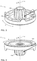
Figur 3- eine perspektivische Darstellung des Gehäusevorderteils der erfindungsgemäßen Strömungsmaschine von der einen Seite; und
Figur 4- die
Darstellung der Figur 3 von der gegenüberliegenden Seite.
- Figure 1
- a longitudinal section through a turbomachine according to the invention;
- Figure 2
- a plan view of the turbo machine according to the invention from the pressure side;
- Figure 3
- a perspective view of the front housing part of the turbomachine according to the invention from one side; and
- Figure 4
- the representation of the
Figure 3 from the opposite side.
Die o.g. Figuren werden in zylindrischen Koordinaten betrachtet. Es erstreckt sich eine Längsachse X, welche auch als Rotationsachse X bezeichnet werden kann. Senkrecht zur Längsachse X erstreckt sich eine radiale Richtung R von der Längsachse X weg. Senkrecht zur radialen Richtung R und um die Längsachse X herum erstreckt sich eine Umfangsrichtung U.The above figures are viewed in cylindrical coordinates. A longitudinal axis X extends, which can also be referred to as the axis of rotation X. A radial direction R extends away from the longitudinal axis X perpendicular to the longitudinal axis X. A circumferential direction U extends perpendicular to the radial direction R and around the longitudinal axis X.
Das Gebläse 1 weist ein Gehäuse 10 auf, welches in ein Gehäusevorderteil 11 und in ein Gehäusehinterteil 12, betrachtet entlang der Rotationsachse X in der wesentlichen Strömungsrichtung des Luftstroms A, unterteilt ist. Das Gehäusevorderteil 11 kann auch als Leitstufen-Oberteil 11 und das Gehäusehinterteil 12 als Lagerschild 12 bezeichnet werden.The blower 1 has a
Dem Luftstrom A zugewandt ist eine Gehäuseabdeckung 13 entlang der Rotationsachse X an dem Leitstufen-Oberteil 11 angeordnet, welche radial mittig eine Durchgangsöffnung (nicht bezeichnet) aufweist, durch welche hindurch der Luftstrom A von dem Gebläse 1 angesogen werden kann. Die Seite des Gebläses 1, welche die Durchlassöffnung aufweist, kann daher auch als Ansaugseite B des Gebläses 1 bezeichnet werden. Die Gehäuseabdeckung 13 kann auch als Ansaughaube 13 bezeichnet werden.Facing the air flow A, a
Der Luftstrom A wird nach der Durchgangsöffnung der Ansaughaube 13 zwischen der Ansaughaube 13 und dem Leitstufen-Oberteil 11 hindurchgeführt. Anschließend tritt der Luftstrom A durch mit Führungselementen 11a versehene Durchgangsöffnungen (nicht bezeichnet) des Leitstufen-Oberteils 11, welche auch als Leitstufen 11a des Leitstufen-Oberteils 11 bezeichnet werden können, durch dieses hindurch und gelangt über weitere Führungselemente 12a des Lagerschilds 12, welche auch als Leitstufen 12a des Lagerschilds 12 bezeichnet werden können, in dessen Innenraum (nicht bezeichnet). Von dem Innenraum des Lagerschilds 12 bzw. des Gehäuses 10 gelangt der Luftstrom A durch weitere Durchlassöffnungen (nicht bezeichnet) wieder aus dem Gehäuse 10 hinaus. Diese Seite des Gehäuses 10 kann als Druckseite C bezeichnet werden.After the passage opening of the
Im bereits beschriebenen Bereich zwischen dem Leitstufen-Oberteil 11 und der Ansaughaube 13 ist ein Laufrad 5 angeordnet, welches eine Mehrzahl von Schaufelblättern 50 aufweist. Wird das Laufrad 5 um die Rotationsachse X des Gebläses 1, welche der Längsachse X entspricht, rotiert, so bewegen die Schaufelräder 50 Luft an der Ansaugseite B in das Gebläse 1 hinein und durch das Gebläse 1 hindurch an der Druckseite C wieder aus dem Gebläse 1 bzw. aus dessen Innenraum hinaus. Hierdurch wird der Luftstrom A erzeugt.In the area already described between the guide stage
Entlang der Rotationsachse X ist dem Laufrad 5 abgewandt ein Elektromotor 3 angeordnet. Der Elektromotor 3 weist einen Stator 30 bzw. einen Ständer 30 auf, welcher eine Mehrzahl von Blechpaketen sowie Spulen (nicht bezeichnet) aufweist. Der Stator 30 des Elektromotors 3 ist durch Verschrauben feststehend an dem Lagerschild 12 angeordnet. Innerhalb des Stators 30 ist ein Rotor 31 bzw. ein Läufer 31 des Elektromotors 3 angeordnet und feststehend mit einer Welle 4 verbunden. Der Rotor 31 des Elektromotors 3 weist eine Mehrzahl von Permanentmagneten (nicht bezeichnet) auf. Zwischen dem Stator 30 und dem Rotor 31 wird in der radialen Richtung R ein radialer Luftspalt (nicht bezeichnet) gebildet.An
Das Laufrad 5 ist feststehend an einem dem Laufrad 5 zugewandten bzw. dem Elektromotor 3 abgewandten Ende (nicht bezeichnet) der Welle 4 angeordnet. Die Welle 4 erstreckt sich entlang der Rotationsachse X durch das Gehäuse 10 hindurch. Auch ist der Rotor 31 des Elektromotors 3 feststehend an einem dem Elektromotor 3 zugewandten bzw. dem Laufrad 5 abgewandten Ende (nicht bezeichnet) der Welle 4 angeordnet. Gleichzeitig ist die Welle 4 über eine Lagerung 2 drehbeweglich mit dem Gehäuse 10 derart verbunden, dass die radial äußeren Lagerelemente der Lagerung 2 feststehend von dem Leitstufen-Oberteil 11 gehalten werden. Hierzu ist das Leitstufen-Oberteil 11 als Spritzgußteil ausgebildet und von radial außen auf die Lagerung 2 aufgespritzt. Auf diese Art und Weise kann die Welle 4 gegenüber dem Gehäuse 10 mittels des Elektromotors 3 rotiert werden. Diese Rotation kann auf das Laufrad 5 übertragen werden.The
In den Innenraum des Lagerschilds 12 bzw. des Gehäuses 11 radial nach außen hineinragend weist der Bereich des Leitstufen-Oberteils 11, welcher die Lagerung 2 umschließt, eine Mehrzahl von Kühlrippen 11b auf, welche sich sowohl radial als auch länglich in der Richtung der Rotationsachse X erstrecken und in der Umfangsrichtung U zueinander beabstandet angeordnet sind. Die Kühlrippen 11b sind einstückig mit dem Leitstufen-Oberteil 11 ausgebildet und dienen dazu, Wärme von der Lagerung 2, welche dort durch Reibung im Betrieb entstehen kann, an den Luftstrom A abzugeben.In the interior of the
Die Lagerung 2, welche auch als Rotorlagerung 2 bezeichnet werden kann, besteht im betrachteten Ausführungsbeispiel auf zwei Lagern 21, 22 in Form von zwei Rillenkugellagern 21, 22, welche entlang der Rotationsachse X zueinander beabstandet radial innenseitig mittels der entsprechenden Lagerelemente (nicht bezeichnet) feststehend, z.B. durch Verpressen, Kleben oder Schrumpfen, auf der Welle 4 und radial außenseitig mittels der entsprechenden Lagerelemente (nicht bezeichnet) durch Spritzgießen mit dem Leitstufen-Oberteil 11 verbunden sind. Radial zwischen den jeweiligen Lagerelementen der beiden Rillenkugellager 21, 22 ist jeweils eine Mehrzahl von Wälzkörpern in Form von Kugeln (nicht bezeichnet) angeordnet, welche die Drehbeweglichkeit der Welle 4 gegenüber dem Gehäuse 10 ermöglichen. Alternativ kann die Lagerung 2 auch mittels eines Patronenlagers 2 umgesetzt werden.The bearing 2, which can also be referred to as rotor bearing 2, consists in the embodiment under consideration on two bearings 21, 22 in the form of two deep groove ball bearings 21, 22, which are spaced apart along the axis of rotation X and are fixed radially on the inside by means of the corresponding bearing elements (not designated) , for example by pressing, gluing or shrinking, on the
Entlang der Rotationsachse X ist zwischen dem Rotor 31 und der Lagerung 2 eine Wuchtscheide 40 auf der Welle 4 angeordnet, welche dem Auswuchten dient.A balancing
Erfindungsgemäß kann auf diese Art und Weise eine bekannte Anordnung der Lagerung 2 zwischen dem Rotor 31 und dem Laufrad 5 entlang der Rotationsachse X umgesetzt werden. Gleichzeitig können die Toleranzen zwischen den beteiligten Elementen, welche den Rotor 31 drehbar gegenüber dem Stator 30 lagern bzw. halten, geringer als bisher bekannt gehalten werden, indem das Gehäuse 10 zweigeteilt ausgebildet wird. Hierdurch kann das Schließmaß der Fertigungs- und Montagetoleranzen zwischen Rotor 31 und Stator 30 geringgehalten werden. Entsprechend können geringe Toleranzen bei der Konstruktion des Gebläses 1 angenommen und insbesondere zwischen Rotor 31 und Stator 30 vorgesehen werden, was insbesondere dem Wirkungsgrad des Elektromotors 3 zugute kommen kann.According to the invention, a known arrangement of the bearing 2 between the
- AA.
- Fluidstrom; Flüssigkeitsstrom; Luftstrom; Strömungsrichtung des Fluids, der Flüssigkeit bzw. der LuftFluid flow; Liquid flow; Airflow; Direction of flow of the fluid, the liquid or the air
- BB.
- Ansaugseite der Strömungsmaschine 1Suction side of the turbo machine 1
- CC.
- Druckseite der Strömungsmaschine 1Pressure side of the turbo machine 1
- RR.
- radiale Richtungradial direction
- UU
- UmfangsrichtungCircumferential direction
- XX
- Längsachse; RotationsachseLongitudinal axis; Axis of rotation
- 11
- Strömungsmaschine; Gebläse; Ventilator; LüfterTurbo machine; Fan; Fan; Fan
- 1010
- Gehäusecasing
- 1111
- Gehäusevorderteil; Leitstufen-OberteilHousing front part; Upper part of the ladder
- 11a11a
-
Führungselemente bzw. Leitstufen des Gehäusevorderteils 11Guide elements or guide steps of the front part of the
housing 11 - 11b11b
-
Kühlrippen des Gehäusevorderteils 11Cooling fins of the front part of the
housing 11 - 1212th
- Gehäusehinterteil; LagerschildRear housing part; Bearing shield
- 12a12a
-
Führungselemente bzw. Leitstufen des Gehäusehinterteils 12Guide elements or guide steps of the
rear housing part 12 - 1313th
- Gehäuseabdeckung; AnsaughaubeHousing cover; Intake hood
- 22
- Lagerung; Rotorlagerung; PatronenlagerStorage; Rotor bearing; Cartridge chamber
- 2121
- erstes Lagerfirst camp
- 2222nd
- zweites Lagersecond camp
- 33
- ElektromotorElectric motor
- 3030th
-
Stator bzw. Ständer des Elektromotors 3Stator or stator of the
electric motor 3 - 3131
-
Rotor bzw. Läufer des Elektromotors 3Rotor or rotor of the
electric motor 3
- 44th
- Wellewave
- 4040
- WuchtscheibeBalancing disc
- 55
- LaufradWheel
- 5050
- SchaufelblätterShovel blades
Claims (15)
mit wenigstens einem Gehäuse (10),
mit wenigstens einem Elektromotor (3)
mit einer Lagerung (2), welche entlang der Rotationsachse (X) der Welle (4) zwischen dem Elektromotor (3) und dem Laufrad (5) angeordnet ist,
dadurch gekennzeichnet, dass
das Gehäuse (10) ein Gehäusevorderteil (11) und ein Gehäusehinterteil (12) aufweist, welche direkt miteinander feststehend verbunden sind,
wobei das Gehäusevorderteil (11) die Lagerung (2) direkt aufnimmt und
wobei das Gehäusehinterteil (12) den Stator (30) direkt aufnimmt.Turbo machine (1)
with at least one housing (10),
with at least one electric motor (3)
with a bearing (2) which is arranged along the axis of rotation (X) of the shaft (4) between the electric motor (3) and the impeller (5),
characterized in that
the housing (10) has a front housing part (11) and a rear housing part (12) which are directly connected to one another in a fixed manner,
wherein the front housing part (11) receives the bearing (2) directly and
wherein the rear housing part (12) receives the stator (30) directly.
das Gehäuse (10) aus dem Gehäusevorderteil (11) und dem Gehäusehinterteil (12) besteht.Turbo machine (1) according to claim 1, characterized in that
the housing (10) consists of the housing front part (11) and the housing rear part (12).
das Gehäusevorderteil (11) durch Umspritzen oder durch Schrumpfen mit der Lagerung (2) verbunden ist.Turbo machine (1) according to claim 1 or 2, characterized in that
the front housing part (11) is connected to the bearing (2) by extrusion coating or by shrinking.
die Lagerung (2) als Patronenlager (2) ausgebildet ist.Turbo machine (1) according to one of the preceding claims, characterized in that
the storage (2) is designed as a cartridge chamber (2).
die Lagerung (2) wenigstens zwei Lager (21, 22), vorzugsweise zwei Rillenkugellager (21, 22), aufweist, welche entlang der Rotationsachse (X) der Welle (4) zueinander beabstandet sind.Turbo machine (1) according to one of claims 1 to 3, characterized in that
the bearing (2) has at least two bearings (21, 22), preferably two deep groove ball bearings (21, 22), which are spaced apart from one another along the axis of rotation (X) of the shaft (4).
die beiden Lager (21, 22) mittels eines Abstandselements oder mittels einer Feder entlang der Rotationsachse (X) der Welle (4) zueinander beabstandet sind.Turbo machine (1) according to claim 5, characterized in that
the two bearings (21, 22) are spaced apart from one another by means of a spacer element or by means of a spring along the axis of rotation (X) of the shaft (4).
an der Welle (4) entlang der Rotationsachse (X) zwischen dem Rotor (31) und der Lagerung (2) eine Wuchtscheibe (40) angeordnet ist.Turbo machine (1) according to one of the preceding claims, characterized in that
a balancing disk (40) is arranged on the shaft (4) along the axis of rotation (X) between the rotor (31) and the bearing (2).
das Gehäusevorderteil (11) eine Mehrzahl von Führungselementen (11a) aufweist, welche ausgebildet sind, den Fluidstrom (A) in der Umfangsrichtung (U) und/oder in der radialen Richtung (R) zu lenken.Turbo machine (1) according to one of the preceding claims, characterized in that
the front housing part (11) has a plurality of guide elements (11a) which are designed to direct the fluid flow (A) in the circumferential direction (U) and / or in the radial direction (R).
das Gehäusehinterteil (12) eine Mehrzahl von Führungselementen (12a) aufweist, welche ausgebildet sind, den Fluidstrom (A) in der Umfangsrichtung (U) und/oder in der radialen Richtung (R) zu lenken.Turbo machine (1) according to one of the preceding claims, characterized in that
the rear housing part (12) has a plurality of guide elements (12a) which are designed to direct the fluid flow (A) in the circumferential direction (U) and / or in the radial direction (R).
das Gehäusevorderteil (11) eine Mehrzahl von Kühlrippen (11b) aufweist, welche ausgebildet sind, Wärme von der Lagerung (2) an den Fluidstrom (A) abzuführen.Turbo machine (1) according to one of the preceding claims, characterized in that
the front housing part (11) has a plurality of cooling fins (11b) which are designed to dissipate heat from the bearing (2) to the fluid flow (A).
zumindest ein Teil der Kühlrippen (11b), vorzugsweise alle Kühlrippen (11b), zumindest abschnittsweise, vorzugsweise vollständig, entlang der Rotationsachse (X) ausgerichtet sind.Turbo machine (1) according to claim 10, characterized in that
at least some of the cooling fins (11b), preferably all of the cooling fins (11b), are aligned at least in sections, preferably completely, along the axis of rotation (X).
das Gehäusevorderteil (11) aus einem relativ gut wärmeleitenden Material ausgebildet ist.Turbo machine (1) according to one of the preceding claims, characterized in that
the front housing part (11) is made of a material that conducts heat relatively well.
an dem Gehäusevorderteil (11) eine Gehäuseabdeckung (13) angeordnet ist,
wobei die Gehäuseabdeckung (13) ausgebildet ist, den Fluidstrom (A) dem Gehäusevorderteil (11) zuzuführen.Turbo machine (1) according to one of the preceding claims, characterized in that
a housing cover (13) is arranged on the housing front part (11),
wherein the housing cover (13) is designed to feed the fluid flow (A) to the housing front part (11).
das Laufrad (5) eine Mehrzahl von Schaufelblättern (50) aufweist, welche zwischen dem Gehäusevorderteil (11) und der Gehäuseabdeckung (13) angeordnet sind.Turbo machine (1) according to claim 13, characterized in that
the impeller (5) has a plurality of blades (50) which are arranged between the front housing part (11) and the housing cover (13).
mit einer Strömungsmaschine (1) gemäß einem der vorangehenden Ansprüche.Household or kitchen appliance
with a turbomachine (1) according to one of the preceding claims.
Applications Claiming Priority (1)
| Application Number | Priority Date | Filing Date | Title |
|---|---|---|---|
| DE102020105981.7A DE102020105981A1 (en) | 2020-03-05 | 2020-03-05 | Turbo machine and household or kitchen appliance herewith |
Publications (1)
| Publication Number | Publication Date |
|---|---|
| EP3875775A1 true EP3875775A1 (en) | 2021-09-08 |
Family
ID=74586817
Family Applications (1)
| Application Number | Title | Priority Date | Filing Date |
|---|---|---|---|
| EP21156153.5A Withdrawn EP3875775A1 (en) | 2020-03-05 | 2021-02-10 | Electric fluid machine with two-part structural casing |
Country Status (2)
| Country | Link |
|---|---|
| EP (1) | EP3875775A1 (en) |
| DE (1) | DE102020105981A1 (en) |
Citations (7)
| Publication number | Priority date | Publication date | Assignee | Title |
|---|---|---|---|---|
| US20100215489A1 (en) * | 2009-02-24 | 2010-08-26 | Dyson Technology Limited | Diffuser |
| JP5466040B2 (en) | 2009-02-24 | 2014-04-09 | ダイソン テクノロジー リミテッド | Rotor assembly |
| EP3121937A2 (en) * | 2015-07-24 | 2017-01-25 | Hangzhou Sanhua Research Institute Co., Ltd. | Electrically driven pump and method for manufacturing the same |
| WO2017098203A1 (en) | 2015-12-11 | 2017-06-15 | Dyson Technology Limited | An electric motor |
| WO2017220324A1 (en) * | 2016-06-20 | 2017-12-28 | Continental Automotive Gmbh | Electric compressor with compact bearing means |
| US20180216635A1 (en) * | 2017-01-31 | 2018-08-02 | Nidec Corporation | Blower and cleaner |
| TWI677629B (en) * | 2017-04-20 | 2019-11-21 | 日商日立環球生活方案股份有限公司 | Electric blower and electric vacuum cleaner with electric blower |
-
2020
- 2020-03-05 DE DE102020105981.7A patent/DE102020105981A1/en not_active Withdrawn
-
2021
- 2021-02-10 EP EP21156153.5A patent/EP3875775A1/en not_active Withdrawn
Patent Citations (9)
| Publication number | Priority date | Publication date | Assignee | Title |
|---|---|---|---|---|
| US20100215489A1 (en) * | 2009-02-24 | 2010-08-26 | Dyson Technology Limited | Diffuser |
| JP5466040B2 (en) | 2009-02-24 | 2014-04-09 | ダイソン テクノロジー リミテッド | Rotor assembly |
| EP2401516B1 (en) | 2009-02-24 | 2018-03-07 | Dyson Technology Limited | Rotor assembly |
| EP3121937A2 (en) * | 2015-07-24 | 2017-01-25 | Hangzhou Sanhua Research Institute Co., Ltd. | Electrically driven pump and method for manufacturing the same |
| WO2017098203A1 (en) | 2015-12-11 | 2017-06-15 | Dyson Technology Limited | An electric motor |
| EP3387741A1 (en) | 2015-12-11 | 2018-10-17 | Dyson Technology Limited | An electric motor |
| WO2017220324A1 (en) * | 2016-06-20 | 2017-12-28 | Continental Automotive Gmbh | Electric compressor with compact bearing means |
| US20180216635A1 (en) * | 2017-01-31 | 2018-08-02 | Nidec Corporation | Blower and cleaner |
| TWI677629B (en) * | 2017-04-20 | 2019-11-21 | 日商日立環球生活方案股份有限公司 | Electric blower and electric vacuum cleaner with electric blower |
Also Published As
| Publication number | Publication date |
|---|---|
| DE102020105981A1 (en) | 2021-09-09 |
Similar Documents
| Publication | Publication Date | Title |
|---|---|---|
| EP2880745B1 (en) | Active cooling of a motor with integrated cooling channel | |
| EP1033494A2 (en) | Radial fan | |
| DE102008008300A1 (en) | Passive fan | |
| DE102013102755A1 (en) | fan | |
| DE7031944U (en) | SIDE CHANNEL COMPRESSOR | |
| EP3405679A1 (en) | Diagonal fan | |
| DE102014106455A1 (en) | Electric machine for use in the automotive sector | |
| WO2014029629A2 (en) | Electrical machine, in particular electric drivemotor | |
| DE202016106538U1 (en) | Diagonal fan | |
| EP3875775A1 (en) | Electric fluid machine with two-part structural casing | |
| EP3875776A1 (en) | Electric fluid machine with two-part structural casing | |
| DE202014104450U1 (en) | Integrated fan blades and fan with the wing | |
| EP3808987A1 (en) | Turbo machine and household or kitchen appliance with same | |
| EP2913533B1 (en) | Stator disc | |
| EP3196471A1 (en) | Monolithic permanent magnet, permanent magnet bearing, vacuum pump and method for producing a monolithic permanent magnet | |
| DE10258346A1 (en) | Brush-less electric motor used e.g. in vacuum cleaner fans has a rotor with a permanent magnet unit for interacting with a stator coil | |
| BE1030312B1 (en) | Fluid machine | |
| DE102011053138A1 (en) | Electrical external rotor motor has stator surface in which several slots are formed such that meandering flow of air is generated by fan wheels with rotor base arranged on stator face at inner side | |
| DE202018106698U1 (en) | Centrifugal fan with integrated cooling function | |
| DE202015101683U1 (en) | Electric motor with pressing cooling air delivery | |
| DE102015105188A1 (en) | Electric motor with pressing cooling air conveying and method for cooling components of the electric motor | |
| DE102005026420B4 (en) | Heat dissipating device | |
| DE102018124063A1 (en) | Blowers for household and small appliances and method for operating them | |
| DE102022104670A1 (en) | flow machine | |
| DE10357547B4 (en) | Turbomolecular pump |
Legal Events
| Date | Code | Title | Description |
|---|---|---|---|
| PUAI | Public reference made under article 153(3) epc to a published international application that has entered the european phase |
Free format text: ORIGINAL CODE: 0009012 |
|
| STAA | Information on the status of an ep patent application or granted ep patent |
Free format text: STATUS: THE APPLICATION HAS BEEN PUBLISHED |
|
| AK | Designated contracting states |
Kind code of ref document: A1 Designated state(s): AL AT BE BG CH CY CZ DE DK EE ES FI FR GB GR HR HU IE IS IT LI LT LU LV MC MK MT NL NO PL PT RO RS SE SI SK SM TR |
|
| STAA | Information on the status of an ep patent application or granted ep patent |
Free format text: STATUS: THE APPLICATION IS DEEMED TO BE WITHDRAWN |
|
| 18D | Application deemed to be withdrawn |
Effective date: 20220310 |