EP3875763B1 - Multi-roller peristaltic pump head - Google Patents
Multi-roller peristaltic pump head Download PDFInfo
- Publication number
- EP3875763B1 EP3875763B1 EP21160171.1A EP21160171A EP3875763B1 EP 3875763 B1 EP3875763 B1 EP 3875763B1 EP 21160171 A EP21160171 A EP 21160171A EP 3875763 B1 EP3875763 B1 EP 3875763B1
- Authority
- EP
- European Patent Office
- Prior art keywords
- pump head
- peristaltic pump
- slot
- arcuate
- base
- Prior art date
- Legal status (The legal status is an assumption and is not a legal conclusion. Google has not performed a legal analysis and makes no representation as to the accuracy of the status listed.)
- Active
Links
- 230000002572 peristaltic effect Effects 0.000 title claims description 61
- 239000002131 composite material Substances 0.000 claims description 18
- 239000007788 liquid Substances 0.000 description 3
- 230000000717 retained effect Effects 0.000 description 3
- 229920002430 Fibre-reinforced plastic Polymers 0.000 description 2
- 239000003822 epoxy resin Substances 0.000 description 2
- 239000011151 fibre-reinforced plastic Substances 0.000 description 2
- 230000007246 mechanism Effects 0.000 description 2
- 238000000034 method Methods 0.000 description 2
- 229920000647 polyepoxide Polymers 0.000 description 2
- 229920001343 polytetrafluoroethylene Polymers 0.000 description 2
- 239000004810 polytetrafluoroethylene Substances 0.000 description 2
- 238000004140 cleaning Methods 0.000 description 1
- 239000011248 coating agent Substances 0.000 description 1
- 238000000576 coating method Methods 0.000 description 1
- 230000006835 compression Effects 0.000 description 1
- 238000007906 compression Methods 0.000 description 1
- 125000004122 cyclic group Chemical group 0.000 description 1
- 238000010586 diagram Methods 0.000 description 1
- 238000006073 displacement reaction Methods 0.000 description 1
- 239000000835 fiber Substances 0.000 description 1
- 239000011152 fibreglass Substances 0.000 description 1
- 239000012530 fluid Substances 0.000 description 1
- 238000009434 installation Methods 0.000 description 1
- 239000003973 paint Substances 0.000 description 1
- -1 polytetrafluoroethylene Polymers 0.000 description 1
- 230000001954 sterilising effect Effects 0.000 description 1
- 238000004659 sterilization and disinfection Methods 0.000 description 1
- 239000000126 substance Substances 0.000 description 1
Images


Classifications
-
- F—MECHANICAL ENGINEERING; LIGHTING; HEATING; WEAPONS; BLASTING
- F04—POSITIVE - DISPLACEMENT MACHINES FOR LIQUIDS; PUMPS FOR LIQUIDS OR ELASTIC FLUIDS
- F04B—POSITIVE-DISPLACEMENT MACHINES FOR LIQUIDS; PUMPS
- F04B43/00—Machines, pumps, or pumping installations having flexible working members
- F04B43/12—Machines, pumps, or pumping installations having flexible working members having peristaltic action
- F04B43/1253—Machines, pumps, or pumping installations having flexible working members having peristaltic action by using two or more rollers as squeezing elements, the rollers moving on an arc of a circle during squeezing
-
- F—MECHANICAL ENGINEERING; LIGHTING; HEATING; WEAPONS; BLASTING
- F04—POSITIVE - DISPLACEMENT MACHINES FOR LIQUIDS; PUMPS FOR LIQUIDS OR ELASTIC FLUIDS
- F04B—POSITIVE-DISPLACEMENT MACHINES FOR LIQUIDS; PUMPS
- F04B43/00—Machines, pumps, or pumping installations having flexible working members
- F04B43/0009—Special features
-
- F—MECHANICAL ENGINEERING; LIGHTING; HEATING; WEAPONS; BLASTING
- F04—POSITIVE - DISPLACEMENT MACHINES FOR LIQUIDS; PUMPS FOR LIQUIDS OR ELASTIC FLUIDS
- F04B—POSITIVE-DISPLACEMENT MACHINES FOR LIQUIDS; PUMPS
- F04B43/00—Machines, pumps, or pumping installations having flexible working members
- F04B43/12—Machines, pumps, or pumping installations having flexible working members having peristaltic action
- F04B43/1238—Machines, pumps, or pumping installations having flexible working members having peristaltic action using only one roller as the squeezing element, the roller moving on an arc of a circle during squeezing
-
- F—MECHANICAL ENGINEERING; LIGHTING; HEATING; WEAPONS; BLASTING
- F04—POSITIVE - DISPLACEMENT MACHINES FOR LIQUIDS; PUMPS FOR LIQUIDS OR ELASTIC FLUIDS
- F04B—POSITIVE-DISPLACEMENT MACHINES FOR LIQUIDS; PUMPS
- F04B43/00—Machines, pumps, or pumping installations having flexible working members
- F04B43/12—Machines, pumps, or pumping installations having flexible working members having peristaltic action
- F04B43/1253—Machines, pumps, or pumping installations having flexible working members having peristaltic action by using two or more rollers as squeezing elements, the rollers moving on an arc of a circle during squeezing
- F04B43/1284—Means for pushing the backing-plate against the tubular flexible member
-
- F—MECHANICAL ENGINEERING; LIGHTING; HEATING; WEAPONS; BLASTING
- F04—POSITIVE - DISPLACEMENT MACHINES FOR LIQUIDS; PUMPS FOR LIQUIDS OR ELASTIC FLUIDS
- F04B—POSITIVE-DISPLACEMENT MACHINES FOR LIQUIDS; PUMPS
- F04B43/00—Machines, pumps, or pumping installations having flexible working members
- F04B43/12—Machines, pumps, or pumping installations having flexible working members having peristaltic action
- F04B43/1253—Machines, pumps, or pumping installations having flexible working members having peristaltic action by using two or more rollers as squeezing elements, the rollers moving on an arc of a circle during squeezing
- F04B43/1292—Pumps specially adapted for several tubular flexible members
-
- F—MECHANICAL ENGINEERING; LIGHTING; HEATING; WEAPONS; BLASTING
- F04—POSITIVE - DISPLACEMENT MACHINES FOR LIQUIDS; PUMPS FOR LIQUIDS OR ELASTIC FLUIDS
- F04B—POSITIVE-DISPLACEMENT MACHINES FOR LIQUIDS; PUMPS
- F04B53/00—Component parts, details or accessories not provided for in, or of interest apart from, groups F04B1/00 - F04B23/00 or F04B39/00 - F04B47/00
- F04B53/16—Casings; Cylinders; Cylinder liners or heads; Fluid connections
-
- F—MECHANICAL ENGINEERING; LIGHTING; HEATING; WEAPONS; BLASTING
- F04—POSITIVE - DISPLACEMENT MACHINES FOR LIQUIDS; PUMPS FOR LIQUIDS OR ELASTIC FLUIDS
- F04B—POSITIVE-DISPLACEMENT MACHINES FOR LIQUIDS; PUMPS
- F04B53/00—Component parts, details or accessories not provided for in, or of interest apart from, groups F04B1/00 - F04B23/00 or F04B39/00 - F04B47/00
- F04B53/22—Arrangements for enabling ready assembly or disassembly
Definitions
- the present disclosure generally relates to peristaltic pumps.
- Rotary peristaltic pumps are typically used for moving liquids through flexible tubing.
- a typical peristaltic pump has a rotor assembly with pinch rollers that apply pressure to the flexible tubing at spaced locations to provide a squeezing action on the tubing against an occlusion bed.
- the occlusion of the tubing creates increased pressure ahead of the squeezed area and reduced pressure behind that area, thereby forcing a liquid through the tubing as the rotor assembly moves the pinch rollers along the tubing.
- the spacing between the occlusion bed and the pinch rollers of the rotor assembly is critical for proper pump operation.
- the spacing between the occlusion bed and the pinch rollers is unforgiving from a tolerance standpoint since it is used both to provide a compressive force between the rotor assembly and occlusion bed and to locate the occlusion bed with respect to the rotor assembly.
- Tubing that is too loose in the pump may lead to flapping while tubing that is too tight may lead to excessive wear on the tubing. Improper installation of the tube may lead to poor pump performance and shortened tube life.
- a multi-roller peristaltic pump may utilize multiple tubes that are compressed by multiple rollers at different times. Such multi-roller peristaltic pumps face additional issues with applying even pressure to the multiple tubes.
- a durable peristaltic pump including an occlusion bed that accommodates multiple tubes, resists movement, and is durable for an operating life of the peristaltic pump.
- US Patent 4,231,668 discloses an apparatus for applying a coating.
- the apparatus includes a rotary variable displacement peristaltic pump for displacing liquid paint through a flexible conduit.
- the apparatus includes a planetary or epicyclic gear system
- the disclosure provides a peristaltic pump head.
- the peristaltic pump head includes a rotor rotatably mounted between a base of the peristaltic pump head and an end cap of the peristaltic pump head.
- the peristaltic pump head includes an arcuate case between the base and the end cap partially surrounding the rotor.
- the peristaltic pump head includes an arcuate occlusion bed removably mounted between the base and the end cap, wherein the arcuate case and the arcuate occlusion bed form a cylindrical body around the rotor.
- the peristaltic pump head includes a locking handle hingedly mounted to the arcuate occlusion bed.
- the locking handle includes a bar extending between a pair of cam members, each cam member including a cam slot that engages a respective pin extending from the base and the end cap.
- a peristaltic pump head including a rotor rotatably mounted between a base of the peristaltic pump head and an end cap of the peristaltic pump head.
- the rotor may include a base plate; an end plate; a central shaft extending through the base plate and the end plate; a central gear driven by the central shaft; and a plurality of planetary shafts mounted between the base plate and the end plate around the central shaft. Each planetary shaft may be connected to a planetary gear in meshed engagement with the central gear.
- the peristaltic pump head may include a pair of composite bushings in each of the base and the end cap rotatably retaining the central shaft.
- the peristaltic pump head ma include a pair of composite bushings in the base plate and the end plate retaining each of the plurality of planetary shafts.
- the disclosure provides a peristaltic pump.
- the peristaltic pump may include a mounting plate attached to an external surface of a housing.
- the mounting plate may have an internal wall defining an opening into the housing for receiving a central rotor shaft of a pump head.
- the peristaltic pump may include an annular collar extending from an external surface of the mounting plate and surrounding the opening, the annual collar including a pair of L-shaped slots opening at an exterior surface of the annular collar.
- the peristaltic pump may include a lock lever pivotably mounted to the mounting plate and movable between a locked position with an end of the lock lever within one of the L-shaped slots and an unlocked position with the end of the lock lever outside of the L-shaped slot.
- the disclosure provides for a multi-roller peristaltic pump head that utilizes an arcuate occlusion bed with a cam locking handle.
- the cam locking handle allows over the center pressure to lock the arcuate occlusion bed to a pump head case.
- the cam locking handle includes a cam member at each end with positive lock into detent for a locking pin at the end of a cam slot. The locking handle stays locked under high occlusion forces.
- the two cam members secure the occlusion bed due to locking points on each side of the occlusion bed.
- the multi-roller peristaltic pump head includes a rotor having a central shaft and a plurality of planetary shafts around the central shaft.
- the multi-roller peristaltic pump head receives two or more tubes.
- a central gear driven by the central shaft drives planetary gears connected to each of the planetary shafts.
- a roller is mounted on each planetary shaft and the planetary shaft rotates the roller over one of the tubes.
- the central shaft is retained in a pair of composite bushings between a pump head base and a pump head end cap.
- Each of the orbital shafts is retained in a pair of composite bushings in a rotor base plate and a rotor end plate.
- the peristaltic pump includes a quick connect feature for mounting the peristaltic pump head on a pump housing.
- the pump housing may include a motor and control circuitry for driving the motor and the peristaltic pump head.
- the quick connect feature may include a mounting plate attached to an external surface of the pump housing.
- the mounting plate may include an annular collar extending from the mounting plate.
- the annular collar may include opposing L-shaped slots.
- the pump head may include a mounting hub having opposing radially extending posts. The posts may be located in the L-shaped slots, and the mounting hub may be turned to engage the pump head to the pump housing.
- the quick connect feature may include a locking lever pivotably mounted to the mounting plate and movable between a locked position with an end of the lock lever within one of the L-shaped slots and an unlocked position with the end of the lock lever outside of the L-shaped slot.
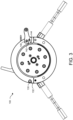
- FIG. 1 is perspective view of an example peristaltic pump head 100 including an arcuate occlusion bed 110.
- the pump head 100 includes an arcuate case 102 that partially surrounds a rotor.
- the pump head 100 may include a base 104 at an end proximate a connector 200, which may be attached to an external surface of a pump housing.
- the arcuate occlusion bed 110 and the arcuate case 102 form a cylindrical body of the pump head 100.
- the pump head 100 may include an end cap 106 at an end distal from the connector 200.
- the pump head 100 may pump fluid from a single source to a single destination via two or more tubes 122, 124.
- the tubes 122, 124 may be connected via a source Y-connector 120 and an outlet Y-connector 126.
- Using two or more tubes with multiple rollers may smooth out the pulses of the peristaltic pump for a more continuous flow.
- the tubes 122, 124 may be positioned with respect to the case 102 by retainers 128.
- the retainers 128 may retain each tube 122, 124 within a respective slot of the case 102.
- the arcuate occlusion bed 110 may be removable from the case 102, base 104, and end cap 106. Tubes 122 and 124 may be inserted into the pump head 100 with the arcuate occlusion bed 110 removed.
- the arcuate occlusion bed 110 may be mounted to the case 102, the base 104, and the end cap 106 on pins 130, 134 ( FIG. 4 ).
- the arcuate occlusion bed 110 may be pressed against the tubes 122, 124 and locked onto the case 102 by a locking handle 112.
- the locking handle 112 is a bar extending between cam members 114 and 116 that engage pins 144, 148 ( FIG. 4 ).
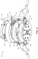
- FIG. 2 is another perspective view of the example peristaltic pump head of FIG. 1 with the end cap 106 removed.
- the pin 130 extends from the end cap 106.
- the arcuate occlusion bed 110 includes a notch 132 that engages the pin 130.
- the arcuate occlusion bed 110 includes a similar notch on the opposite side that engages the pin 134. Accordingly, the arcuate occlusion bed 110 may pivot about the pins 130, 134.
- the cam members 114 and 116 may be pivotably mounted to the arcuate occlusion bed 110 via pins 140, 146 ( FIG. 4 ).
- the cam members 114 and 116 may include a cam slot 142, 147 ( FIG. 5 ).
- the cam slots 142, 147 may open at an end opposite the handle 112 and extend into the cam members 114, 116 in an arc centered at the pins 140, 146.
- the pins 144, 148 may enter the slots 142, 147 and slide along the arc surface to an internal end of the slot. The pressure of the arc surface against the pins 144, 148 may pivot the occlusion bed 110 toward the case 102, compressing the tubes 122, 124.
- a rotor 150 is located within the case 102.
- the rotor 150 may include a base plate 164 ( FIG. 5 ), an end plate 166, a central shaft 152, and a plurality of planetary shafts 156.
- the central shaft 152 may extend from outside the base 104 to the end cap 106, passing through the base plate 164 and the end plate 166.
- Each of the plurality of planetary shafts 156 may extend from the base plate 164 to the end plate 166.
- the base plate 164 and the end plate 166 may include composite bushings 154 to allow the central shaft 152 to rotate within the base plate 164 and end plate 166.
- the base plate 164 and the end plate 166 may include composite bushings 158 to retain each of the planetary shafts 156 and allow rotation of the planetary shafts 156.
- the composite bushings 154 and composite bushings 158 may be a composite material such as a fiber reinforced polymer (FRP).
- the composite bearings may include continuously wound polytetrafluoroethylene (PTFE) and high strength fibers encapsulated in an internally lubricated, high-temperature filled epoxy resin or a fiberglass encapsulated in a high-temperature epoxy resin.
- the composite bushings may provide a higher pressure-velocity (PV) rating than conventional bearings and produce less noise.
- the composite bushings may tolerate cleaning and sterilization processes that may utilize chemicals and high temperatures.
- the composite bushings may be replaceable.
- FIG. 3 is a front view of the example peristaltic pump head 100 of FIG. 1 .
- the end cap 106 is not shown.
- the shape of the notch 132 and the cam slot 142 are shown.
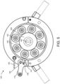
- FIG. 4 is a top perspective view of the example peristaltic pump head of FIG. 1 with the arcuate occlusion bed 110 removed.
- the tubes 122, 124 pass over rollers 170.
- Each roller 170 may include a narrow portion 172 having a first diameter and a wide portion 174 having a second diameter. The second diameter may be greater than the first diameter.
- the wide portion 174 may compress the tube 122, 124 as the roller squeezes the tube 122, 124 against the occlusion bed 110.
- the narrow portion 172 may not compress the tube 122, 124.
- the rollers 170 may alternate orientations around the central shaft 152 such that the tubes 122, 124 alternatingly pass over a narrow portion 172 and a wide portion 174. Accordingly, one tube 122 may be compressed while the other tube 124 is not compressed. This alternating compression may smooth out the pulses of the pump for a more constant flow rate.
- the peristaltic pump head 100 may include an open head sensor 190.
- the open head sensor 190 may include a switch (e.g., a button) that opens when the arcuate occlusion bed 110 is attached to the arcuate case 102.
- the open head sensor 190 may be located on the base 104 such that the arcuate occlusion bed 110 compresses the switch.
- the open head sensor 190 may be connected to a pump 300 ( FIG. 6 ) via a wire 192.
- the pump 300 may stop rotation of the rotor 140 in response to the open head sensor 190 indicating that the arcuate occlusion bed 110 is not attached to the arcuate case 102.
- FIG. 5 is a back view of the example peristaltic pump head of FIG. 1 with the base 104 removed.
- An adaptor 180 may be attached to the end of the central shaft 152.
- the adaptor 180 may include a rectangular end or other shape corresponding to a pump drive.
- a central gear 160 may be connected to the central shaft 152.
- a respective planetary gear 162 may be connected to each of the planetary shafts 156.
- the planetary shafts 156 may be retained in the base plate 164 within composite bushings.
- the central gear 160 may mesh with each of the planetary gears 162. Accordingly, rotation of the central shaft 152 via the adaptor 180 may rotate the central gear 160, which in turn rotates each of the planetary gears 162, the planetary shafts 156, and the rollers 170.
- the cam member 116 is visible in FIG. 5 . Similar to the cam member 114, the cam member 116 is pivotably mounted on a pin 146. The cam member 116 includes a slot 147 that engages a pin 148. The cam slot 147 is arc shaped about the pin 146. The cam member 116 is aligned with the cam member 114 such that pressure on the handle 112 simultaneously pivots both the cam member 114 and 116 to receive the respective pins 144, 148. Accordingly, over the center pressure on the handle 112 closes the occlusion bed 110 without twisting.
- FIG. 6 is a side view of the example peristaltic pump head 100 of FIG. 1 mounted to a pump 300 via a connector 200.
- the pump 300 may include a motor and control circuitry (not shown) for rotating the central shaft 152 via the adaptor 180.
- the connector 200 may be attached to the pump 300 via fasteners such as screws or bolts.
- the connector 200 may include an annular collar 220 that receives a mounting hub of the pump head 100.
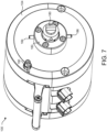
- FIG. 7 is a rear perspective view of the example peristaltic pump head of FIG. 1 showing the mounting hub 182.
- the mounting hub 182 may be attached to the base 104 via fasteners such as screws or bolts.
- the mounting hub 182 may have a cylindrical shape with a diameter slightly less than an internal diameter of the annular collar 220.
- the mounting hub 182 may include posts 184, 186 that extend radially from opposite sides of the mounting hub 182.
- FIG. 8 is a perspective view of an example connector 200 including a mounting plate 210 and annular collar 220.
- the mounting plate 210 may be a disc with a central opening to allow the central shaft 152 to pass into the pump 300.
- the mounting plate 210 may include openings that correspond to mounting holes in the pump 300.
- the annular collar 220 may be attached to the mounting plate 210 via fasteners from a back side of the mounting plate 210.
- the mounting plate 210 may be selected with openings corresponding to a particular model of pump 300.
- the annular collar 220 may include L-shaped slots 224, 226.
- Each of the L-shaped slots 224, 226 may have an opening at an exterior surface of the annular collar 220 and turn at a right angle to extend circumferentially within the annular collar 220.
- the L-shaped slots 224, 226 may receive the posts 184, 186.
- a lock lever 230 may be pivotably mounted to the mounting plate 210 and aligned with one of the L-shaped slots 224.
- a biasing element 232 such as a spring may bias the lock lever 230 into the L-shaped slot 224.
- FIG. 9 is a plan view of the example connector 200 of FIG. 9 with the annular collar 220 shown as transparent.
- the lock lever 230 may have a locking end 234 that is biased into the L-shaped slot 224.
- a curved surface 236 may face the interior of the annular collar 220.
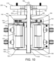
- FIG. 10 is a cross-sectional view of the example peristaltic pump head 100 of FIG. 1 .
- composite bushings 154 may be located in the base 104, base plate 164, end plate 166, and end cap 106 to allow the central shaft 152 to rotate.
- Composite bushings 158 may be located in the base plate 164 and the end plate 166 to allow the planetary shafts 156 and rollers 170 to rotate.
Landscapes
- Engineering & Computer Science (AREA)
- Mechanical Engineering (AREA)
- General Engineering & Computer Science (AREA)
- Reciprocating Pumps (AREA)
Description
- This application claims priority to
U.S. Provisional Application Number 62/983,982 titled "MULTI-ROLLER PERISTALTIC PUMP HEAD," filed March 2, 2020 U.S. Patent Application Number 17/178626 titled "MULTI-ROLLER PERISTALTIC PUMP HEAD," filed February 18, 2021 - The present disclosure generally relates to peristaltic pumps.
- Rotary peristaltic pumps are typically used for moving liquids through flexible tubing. A typical peristaltic pump has a rotor assembly with pinch rollers that apply pressure to the flexible tubing at spaced locations to provide a squeezing action on the tubing against an occlusion bed. The occlusion of the tubing creates increased pressure ahead of the squeezed area and reduced pressure behind that area, thereby forcing a liquid through the tubing as the rotor assembly moves the pinch rollers along the tubing.
- The spacing between the occlusion bed and the pinch rollers of the rotor assembly is critical for proper pump operation. The spacing between the occlusion bed and the pinch rollers is unforgiving from a tolerance standpoint since it is used both to provide a compressive force between the rotor assembly and occlusion bed and to locate the occlusion bed with respect to the rotor assembly. Tubing that is too loose in the pump may lead to flapping while tubing that is too tight may lead to excessive wear on the tubing. Improper installation of the tube may lead to poor pump performance and shortened tube life.
- Various mechanisms exist in the related art for moving the occlusion bed with respect to the rotor assembly. Such mechanisms, however, often allow movement of the occlusion bed, especially when high pressures and cyclic loading are applied as the rotor assembly rotates. Further, a multi-roller peristaltic pump may utilize multiple tubes that are compressed by multiple rollers at different times. Such multi-roller peristaltic pumps face additional issues with applying even pressure to the multiple tubes.
- Accordingly, there is a need for a durable peristaltic pump including an occlusion bed that accommodates multiple tubes, resists movement, and is durable for an operating life of the peristaltic pump.
-
US Patent 4,231,668 discloses an apparatus for applying a coating. The apparatus includes a rotary variable displacement peristaltic pump for displacing liquid paint through a flexible conduit. The apparatus includes a planetary or epicyclic gear system - The following presents a simplified summary of one or more aspects of the invention in order to provide a basic understanding of such aspects. This summary is not an extensive overview of all contemplated aspects, and is intended to neither identify key or critical elements of all aspects nor delineate the scope of any or all aspects. Its purpose is to present some concepts of one or more aspects in a simplified form as a prelude to the more detailed description that is presented later.
- In one aspect, the disclosure provides a peristaltic pump head. The peristaltic pump head includes a rotor rotatably mounted between a base of the peristaltic pump head and an end cap of the peristaltic pump head. The peristaltic pump head includes an arcuate case between the base and the end cap partially surrounding the rotor. The peristaltic pump head includes an arcuate occlusion bed removably mounted between the base and the end cap, wherein the arcuate case and the arcuate occlusion bed form a cylindrical body around the rotor. The peristaltic pump head includes a locking handle hingedly mounted to the arcuate occlusion bed. The locking handle includes a bar extending between a pair of cam members, each cam member including a cam slot that engages a respective pin extending from the base and the end cap.
- In another aspect the disclosure provides a peristaltic pump head including a rotor rotatably mounted between a base of the peristaltic pump head and an end cap of the peristaltic pump head. The rotor may include a base plate; an end plate; a central shaft extending through the base plate and the end plate; a central gear driven by the central shaft; and a plurality of planetary shafts mounted between the base plate and the end plate around the central shaft. Each planetary shaft may be connected to a planetary gear in meshed engagement with the central gear. The peristaltic pump head may include a pair of composite bushings in each of the base and the end cap rotatably retaining the central shaft. The peristaltic pump head ma include a pair of composite bushings in the base plate and the end plate retaining each of the plurality of planetary shafts.
- In another aspect, the disclosure provides a peristaltic pump. The peristaltic pump may include a mounting plate attached to an external surface of a housing. The mounting plate may have an internal wall defining an opening into the housing for receiving a central rotor shaft of a pump head. The peristaltic pump may include an annular collar extending from an external surface of the mounting plate and surrounding the opening, the annual collar including a pair of L-shaped slots opening at an exterior surface of the annular collar. The peristaltic pump may include a lock lever pivotably mounted to the mounting plate and movable between a locked position with an end of the lock lever within one of the L-shaped slots and an unlocked position with the end of the lock lever outside of the L-shaped slot.
- These and other aspects of the invention or general disclosure will become more fully understood upon a review of the detailed description, which follows.
-
-
FIG. 1 is perspective view of an example peristaltic pump head including an arcuate occlusion bed, according to an aspect of the disclosure. -
FIG. 2 is another perspective view of the example peristaltic pump head ofFIG. 1 with an end cap removed, according to an aspect of the disclosure. -
FIG. 3 is a front view of the example peristaltic pump head ofFIG. 1 , according to an aspect of the disclosure. -
FIG. 4 is a top perspective view of the example peristaltic pump head ofFIG. 1 with the arcuate occlusion bed removed, according to an aspect of the disclosure. -
FIG. 5 is a back view of the example peristaltic pump head ofFIG. 1 with a base removed, according to an aspect of the disclosure. -
FIG. 6 is a side view of the example peristaltic pump head ofFIG. 1 mounted to a pump, according to an aspect of the disclosure. -
FIG. 7 is a rear perspective view of the example peristaltic pump head ofFIG. 1 , according to an aspect of the disclosure. -
FIG. 8 is a perspective view of an example connector including a mounting plate and annular collar, according to an aspect of the disclosure. -
FIG. 9 is a plan view of the example connector ofFIG. 8 with a transparent annular collar, according to an aspect of the disclosure. -
FIG. 10 is a cross-sectional view of the example peristaltic pump head ofFIG. 1 , according to an aspect of the disclosure. - The detailed description set forth below in connection with the appended drawings is intended as a description of various configurations and is not intended to represent the only configurations in which the concepts described herein may be practiced. The detailed description includes specific details for the purpose of providing a thorough understanding of various concepts. However, it will be apparent to those skilled in the art that these concepts may be practiced without these specific details. In some instances, well known components are shown in block diagram form in order to avoid obscuring such concepts.
- In an aspect, the disclosure provides for a multi-roller peristaltic pump head that utilizes an arcuate occlusion bed with a cam locking handle. The cam locking handle allows over the center pressure to lock the arcuate occlusion bed to a pump head case. The cam locking handle includes a cam member at each end with positive lock into detent for a locking pin at the end of a cam slot. The locking handle stays locked under high occlusion forces. The two cam members secure the occlusion bed due to locking points on each side of the occlusion bed.
- In another aspect, the multi-roller peristaltic pump head includes a rotor having a central shaft and a plurality of planetary shafts around the central shaft. The multi-roller peristaltic pump head receives two or more tubes. A central gear driven by the central shaft drives planetary gears connected to each of the planetary shafts. A roller is mounted on each planetary shaft and the planetary shaft rotates the roller over one of the tubes. The central shaft is retained in a pair of composite bushings between a pump head base and a pump head end cap. Each of the orbital shafts is retained in a pair of composite bushings in a rotor base plate and a rotor end plate.
- In another aspect, the peristaltic pump includes a quick connect feature for mounting the peristaltic pump head on a pump housing. The pump housing may include a motor and control circuitry for driving the motor and the peristaltic pump head. The quick connect feature may include a mounting plate attached to an external surface of the pump housing. The mounting plate may include an annular collar extending from the mounting plate. The annular collar may include opposing L-shaped slots. The pump head may include a mounting hub having opposing radially extending posts. The posts may be located in the L-shaped slots, and the mounting hub may be turned to engage the pump head to the pump housing. The quick connect feature may include a locking lever pivotably mounted to the mounting plate and movable between a locked position with an end of the lock lever within one of the L-shaped slots and an unlocked position with the end of the lock lever outside of the L-shaped slot.
-
FIG. 1 is perspective view of an exampleperistaltic pump head 100 including anarcuate occlusion bed 110. Thepump head 100 includes anarcuate case 102 that partially surrounds a rotor. Thepump head 100 may include a base 104 at an end proximate aconnector 200, which may be attached to an external surface of a pump housing. Thearcuate occlusion bed 110 and thearcuate case 102 form a cylindrical body of thepump head 100. Thepump head 100 may include anend cap 106 at an end distal from theconnector 200. - In an aspect, the
pump head 100 may pump fluid from a single source to a single destination via two ormore tubes tubes connector 120 and an outlet Y-connector 126. Using two or more tubes with multiple rollers may smooth out the pulses of the peristaltic pump for a more continuous flow. Thetubes case 102 byretainers 128. For example, theretainers 128 may retain eachtube case 102. - The
arcuate occlusion bed 110 may be removable from thecase 102,base 104, andend cap 106.Tubes pump head 100 with thearcuate occlusion bed 110 removed. Thearcuate occlusion bed 110 may be mounted to thecase 102, thebase 104, and theend cap 106 onpins 130, 134 (FIG. 4 ). Thearcuate occlusion bed 110 may be pressed against thetubes case 102 by alocking handle 112. The locking handle 112 is a bar extending betweencam members FIG. 4 ). -
FIG. 2 is another perspective view of the example peristaltic pump head ofFIG. 1 with theend cap 106 removed. Thepin 130 extends from theend cap 106. Thearcuate occlusion bed 110 includes anotch 132 that engages thepin 130. Thearcuate occlusion bed 110 includes a similar notch on the opposite side that engages thepin 134. Accordingly, thearcuate occlusion bed 110 may pivot about thepins cam members arcuate occlusion bed 110 viapins 140, 146 (FIG. 4 ). Thecam members cam slot 142, 147 (FIG. 5 ). Thecam slots handle 112 and extend into thecam members pins handle 112 is pressed down (toward the case 102), thepins slots pins occlusion bed 110 toward thecase 102, compressing thetubes - A
rotor 150 is located within thecase 102. Therotor 150 may include a base plate 164 (FIG. 5 ), anend plate 166, acentral shaft 152, and a plurality ofplanetary shafts 156. Thecentral shaft 152 may extend from outside the base 104 to theend cap 106, passing through thebase plate 164 and theend plate 166. Each of the plurality ofplanetary shafts 156 may extend from thebase plate 164 to theend plate 166. - In an aspect, the
base plate 164 and theend plate 166 may includecomposite bushings 154 to allow thecentral shaft 152 to rotate within thebase plate 164 andend plate 166. Thebase plate 164 and theend plate 166 may includecomposite bushings 158 to retain each of theplanetary shafts 156 and allow rotation of theplanetary shafts 156. In an aspect, thecomposite bushings 154 andcomposite bushings 158 may be a composite material such as a fiber reinforced polymer (FRP). For example, the composite bearings may include continuously wound polytetrafluoroethylene (PTFE) and high strength fibers encapsulated in an internally lubricated, high-temperature filled epoxy resin or a fiberglass encapsulated in a high-temperature epoxy resin. In an aspect, the composite bushings may provide a higher pressure-velocity (PV) rating than conventional bearings and produce less noise. The composite bushings may tolerate cleaning and sterilization processes that may utilize chemicals and high temperatures. The composite bushings may be replaceable. -
FIG. 3 is a front view of the exampleperistaltic pump head 100 ofFIG. 1 . Theend cap 106 is not shown. The shape of thenotch 132 and thecam slot 142 are shown. -
FIG. 4 is a top perspective view of the example peristaltic pump head ofFIG. 1 with thearcuate occlusion bed 110 removed. Thetubes rollers 170. Eachroller 170 may include anarrow portion 172 having a first diameter and awide portion 174 having a second diameter. The second diameter may be greater than the first diameter. Thewide portion 174 may compress thetube tube occlusion bed 110. Thenarrow portion 172 may not compress thetube rollers 170 may alternate orientations around thecentral shaft 152 such that thetubes narrow portion 172 and awide portion 174. Accordingly, onetube 122 may be compressed while theother tube 124 is not compressed. This alternating compression may smooth out the pulses of the pump for a more constant flow rate. - The
peristaltic pump head 100 may include anopen head sensor 190. Theopen head sensor 190 may include a switch (e.g., a button) that opens when thearcuate occlusion bed 110 is attached to thearcuate case 102. For example, as illustrated, theopen head sensor 190 may be located on the base 104 such that thearcuate occlusion bed 110 compresses the switch. Theopen head sensor 190 may be connected to a pump 300 (FIG. 6 ) via awire 192. Thepump 300 may stop rotation of therotor 140 in response to theopen head sensor 190 indicating that thearcuate occlusion bed 110 is not attached to thearcuate case 102. -
FIG. 5 is a back view of the example peristaltic pump head ofFIG. 1 with the base 104 removed. Anadaptor 180 may be attached to the end of thecentral shaft 152. Theadaptor 180 may include a rectangular end or other shape corresponding to a pump drive. Acentral gear 160 may be connected to thecentral shaft 152. A respectiveplanetary gear 162 may be connected to each of theplanetary shafts 156. As discussed above, theplanetary shafts 156 may be retained in thebase plate 164 within composite bushings. Thecentral gear 160 may mesh with each of theplanetary gears 162. Accordingly, rotation of thecentral shaft 152 via theadaptor 180 may rotate thecentral gear 160, which in turn rotates each of theplanetary gears 162, theplanetary shafts 156, and therollers 170. - The
cam member 116 is visible inFIG. 5 . Similar to thecam member 114, thecam member 116 is pivotably mounted on apin 146. Thecam member 116 includes aslot 147 that engages apin 148. Thecam slot 147 is arc shaped about thepin 146. Thecam member 116 is aligned with thecam member 114 such that pressure on thehandle 112 simultaneously pivots both thecam member respective pins handle 112 closes theocclusion bed 110 without twisting. -
FIG. 6 is a side view of the exampleperistaltic pump head 100 ofFIG. 1 mounted to apump 300 via aconnector 200. Thepump 300 may include a motor and control circuitry (not shown) for rotating thecentral shaft 152 via theadaptor 180. Theconnector 200 may be attached to thepump 300 via fasteners such as screws or bolts. Theconnector 200 may include anannular collar 220 that receives a mounting hub of thepump head 100. -
FIG. 7 is a rear perspective view of the example peristaltic pump head ofFIG. 1 showing the mountinghub 182. The mountinghub 182 may be attached to thebase 104 via fasteners such as screws or bolts. The mountinghub 182 may have a cylindrical shape with a diameter slightly less than an internal diameter of theannular collar 220. The mountinghub 182 may includeposts hub 182. -
FIG. 8 is a perspective view of anexample connector 200 including a mountingplate 210 andannular collar 220. The mountingplate 210 may be a disc with a central opening to allow thecentral shaft 152 to pass into thepump 300. The mountingplate 210 may include openings that correspond to mounting holes in thepump 300. Theannular collar 220 may be attached to the mountingplate 210 via fasteners from a back side of the mountingplate 210. The mountingplate 210 may be selected with openings corresponding to a particular model ofpump 300. Theannular collar 220 may include L-shapedslots slots annular collar 220 and turn at a right angle to extend circumferentially within theannular collar 220. The L-shapedslots posts lock lever 230 may be pivotably mounted to the mountingplate 210 and aligned with one of the L-shapedslots 224. A biasingelement 232 such as a spring may bias thelock lever 230 into the L-shapedslot 224. -
FIG. 9 is a plan view of theexample connector 200 ofFIG. 9 with theannular collar 220 shown as transparent. Thelock lever 230 may have a lockingend 234 that is biased into the L-shapedslot 224. Acurved surface 236 may face the interior of theannular collar 220. When one of theposts slot 224 and rotated, theposts curved surface 236, overcome the biasing force, and travel to anend 240 of the L-shapedslot 224. Once thepost end 234, the lockingend 234 may enter the L-shapedslot 224 behind thepost post end 240 of the L-shaped slot. Thelock lever 230 may be rotated against the biasing force to release thepost pump head 100. -
FIG. 10 is a cross-sectional view of the exampleperistaltic pump head 100 ofFIG. 1 . As discussed above,composite bushings 154 may be located in thebase 104,base plate 164,end plate 166, andend cap 106 to allow thecentral shaft 152 to rotate.Composite bushings 158 may be located in thebase plate 164 and theend plate 166 to allow theplanetary shafts 156 androllers 170 to rotate. - This written description uses examples to disclose aspects of the invention, including the preferred embodiments, and also to enable any person skilled in the art to practice the aspects thereof, including making and using any devices or systems and performing any incorporated methods. The scope of the present invention is solely defined by the appended claims.
Claims (8)
- A peristaltic pump head (100), comprising:a rotor (150) rotatably mounted between a base (104) of the peristaltic pump head and an end cap (106) of the peristaltic pump head;an arcuate case (102) between the base and the end cap partially surrounding the rotor; andan arcuate occlusion bed (110) removably mounted between the base and the end cap, wherein the arcuate case and the arcuate occlusion bed form a cylindrical body around the rotor; characterized bya locking handle (112) hingedly mounted to the arcuate occlusion bed, wherein the locking handle includes a bar extending between a pair of cam members (114, 116), each cam member including a cam slot (142, 147) that engages a respective pin (144, 148) extending from the base and the end cap.
- The peristaltic pump head of claim 1, wherein the rotor comprises:a base plate (164);an end plate (166);a central shaft (152) extending through the base plate and the end plate;a central gear (160) driven by the central shaft; anda plurality of planetary shafts (156) mounted between the base plate and the end plate around the central shaft, each planetary shaft connected to a planetary gear (162) in meshed engagement with the central gear..
- The peristaltic pump head of claim 2, further comprising:a pair of composite bushings (154) in each of the base and the end cap rotatably retaining the central shaft; anda pair of composite bushings (158) in the base plate and the end plate retaining each of the plurality of planetary shafts..
- The peristaltic pump head of claim 2 or 3, wherein at least one of the plurality of planetary shafts includes a roller (170) having a first portion (172) with a first diameter and a second portion (174) with a second diameter that is greater than the first diameter.
- The peristaltic pump head of claim 4, further comprising:a first tube (122) extending from a first slot in the arcuate case over the rotor to a second slot in the arcuate case; anda second tube (124) extending from a third slot in the arcuate case over the rotor to a fourth slot in the arcuate case, wherein the first tube is aligned with the first portion of the at least one of the plurality of planetary shafts when the second tube is aligned with the second portion of the at least one of the plurality of planetary shafts.
- The peristaltic pump head of claim 5, wherein the first slot, second slot, third slot, and fourth slot are located between the pair of cam members.
- The peristaltic pump head of claim 5 or 6, wherein each of the plurality of planetary shafts includes a respective roller (170) having the first portion (172) and the second portion (174), and wherein an orientation of each of the plurality of rollers alternates around the central shaft.
- The peristaltic pump head of any one of claims 1 to 7, further comprising a cylindrical mounting hub (182) configured to be received within an annular collar (220), wherein the mounting hub includes a pair of radially extending posts (184, 186).
Applications Claiming Priority (2)
| Application Number | Priority Date | Filing Date | Title |
|---|---|---|---|
| US202062983982P | 2020-03-02 | 2020-03-02 | |
| US17/178,626 US11773839B2 (en) | 2020-03-02 | 2021-02-18 | Multi-roller peristaltic pump head |
Publications (2)
| Publication Number | Publication Date |
|---|---|
| EP3875763A1 EP3875763A1 (en) | 2021-09-08 |
| EP3875763B1 true EP3875763B1 (en) | 2023-05-10 |
Family
ID=74856592
Family Applications (1)
| Application Number | Title | Priority Date | Filing Date |
|---|---|---|---|
| EP21160171.1A Active EP3875763B1 (en) | 2020-03-02 | 2021-03-02 | Multi-roller peristaltic pump head |
Country Status (2)
| Country | Link |
|---|---|
| US (1) | US11773839B2 (en) |
| EP (1) | EP3875763B1 (en) |
Family Cites Families (16)
| Publication number | Priority date | Publication date | Assignee | Title |
|---|---|---|---|---|
| US2956734A (en) * | 1953-08-27 | 1960-10-18 | Doyle Vacuum Cleaner Co | Vacuum cleaner head assembly |
| GB1417146A (en) * | 1972-08-09 | 1975-12-10 | Rank Organisation Ltd | Peristaltic pumps |
| US4231668A (en) * | 1978-10-05 | 1980-11-04 | The Sherwin-Williams Company | Liquid power driven coating apparatus |
| GB2138511B (en) * | 1983-04-14 | 1987-03-25 | Smith & Nephew Ass | Peristaltic pump and pumphead therefor |
| US5021048A (en) * | 1989-08-04 | 1991-06-04 | Medtronic, Inc. | Blood pump drive system |
| EP0522493B2 (en) * | 1991-07-09 | 2001-10-24 | FASTER S.r.l. | Quick acting coupling for the simultaneous make-up and release of the connection for several couplings and/or plugs, in particular coupling-manifold for tool front connector on vehicles |
| US7331770B2 (en) * | 2003-01-14 | 2008-02-19 | Oyaski Michael F | Disposable two-stage pump |
| US7722338B2 (en) * | 2005-02-10 | 2010-05-25 | Novasys Medical, Inc. | Peristaltic pump providing simplified loading and improved tubing kink resistance |
| EP2138511A1 (en) * | 2008-06-27 | 2009-12-30 | Max-Planck-Gesellschaft zur Förderung der Wissenschaften e.V. | HER3 as a determinant for the prognosis of melanoma |
| DE102009000299A1 (en) * | 2009-01-19 | 2010-07-22 | Robert Bosch Gmbh | peristaltic pump |
| US9518576B1 (en) * | 2010-07-15 | 2016-12-13 | Elemental Scientific, Inc. | Peristaltic pump |
| US8985969B2 (en) * | 2011-02-10 | 2015-03-24 | Mitsubishi Heavy Industries, Ltd. | Pump configuration |
| CA2791344C (en) * | 2012-09-26 | 2019-07-16 | Capmatic Ltee | Peristaltic pump |
| US20160010635A1 (en) * | 2014-07-09 | 2016-01-14 | Perkinelmer Health Sciences, Inc. | Peristaltic pump and related methods |
| US20180023555A1 (en) * | 2016-07-22 | 2018-01-25 | Mallinckrodt Nuclear Medicine Llc | Pump for operation in radioactive environment |
| US11041584B2 (en) * | 2017-11-20 | 2021-06-22 | Parker-Hannifin Corporation | Latch mechanism for multi-coupling |
-
2021
- 2021-02-18 US US17/178,626 patent/US11773839B2/en active Active
- 2021-03-02 EP EP21160171.1A patent/EP3875763B1/en active Active
Also Published As
| Publication number | Publication date |
|---|---|
| EP3875763A1 (en) | 2021-09-08 |
| US11773839B2 (en) | 2023-10-03 |
| US20220260069A1 (en) | 2022-08-18 |
Similar Documents
| Publication | Publication Date | Title |
|---|---|---|
| US7934912B2 (en) | Peristaltic pump assembly with cassette and mounting pin arrangement | |
| US5897300A (en) | Quick-release bolt for use with pump housing | |
| EP0796396B1 (en) | Linear peristaltic pump with reshaping fingers interdigitated with pumping elements | |
| US4568255A (en) | Peristaltic roller pump | |
| US7712802B2 (en) | Cassette clamping mechanism | |
| US4473342A (en) | Peristaltic pumping device | |
| EP0346784B1 (en) | Peristaltic pump adapted to operate simultaneously on two lines | |
| US20090053085A1 (en) | Peristalitic pump assembly and method for attaching a cassette thereto | |
| CN108496005B (en) | Micro-dose peristaltic pump for micro-dosed fluids | |
| US4604038A (en) | Remotely operable peristaltic pump | |
| US5092749A (en) | Fluid pump drive mechanism | |
| WO2013043322A1 (en) | Peristaltic pump cassette and method of installing same | |
| US6811386B2 (en) | Peristaltic pump with preformed tube | |
| US5263831A (en) | Peristaltic pump | |
| EP3875763B1 (en) | Multi-roller peristaltic pump head | |
| CN113474022B (en) | Infusion device including pumping mechanism | |
| CN114294207B (en) | Peristaltic pump capable of accurately controlling flow | |
| US5871341A (en) | Peristaltic pump driven pump roller apparatus and methodology | |
| DE602004003814T2 (en) | ROTARY PISTON OR ENGINE WITH A SINGLE WING | |
| Belew | Remotely operable peristaltic pump |
Legal Events
| Date | Code | Title | Description |
|---|---|---|---|
| PUAI | Public reference made under article 153(3) epc to a published international application that has entered the european phase |
Free format text: ORIGINAL CODE: 0009012 |
|
| STAA | Information on the status of an ep patent application or granted ep patent |
Free format text: STATUS: THE APPLICATION HAS BEEN PUBLISHED |
|
| AK | Designated contracting states |
Kind code of ref document: A1 Designated state(s): AL AT BE BG CH CY CZ DE DK EE ES FI FR GB GR HR HU IE IS IT LI LT LU LV MC MK MT NL NO PL PT RO RS SE SI SK SM TR |
|
| STAA | Information on the status of an ep patent application or granted ep patent |
Free format text: STATUS: REQUEST FOR EXAMINATION WAS MADE |
|
| 17P | Request for examination filed |
Effective date: 20220303 |
|
| RBV | Designated contracting states (corrected) |
Designated state(s): AL AT BE BG CH CY CZ DE DK EE ES FI FR GB GR HR HU IE IS IT LI LT LU LV MC MK MT NL NO PL PT RO RS SE SI SK SM TR |
|
| RAP1 | Party data changed (applicant data changed or rights of an application transferred) |
Owner name: MASTERFLEX, LLC |
|
| RIC1 | Information provided on ipc code assigned before grant |
Ipc: F04B 53/22 20060101ALI20221220BHEP Ipc: F04B 53/16 20060101ALI20221220BHEP Ipc: F04B 43/12 20060101AFI20221220BHEP |
|
| GRAP | Despatch of communication of intention to grant a patent |
Free format text: ORIGINAL CODE: EPIDOSNIGR1 |
|
| STAA | Information on the status of an ep patent application or granted ep patent |
Free format text: STATUS: GRANT OF PATENT IS INTENDED |
|
| INTG | Intention to grant announced |
Effective date: 20230127 |
|
| GRAS | Grant fee paid |
Free format text: ORIGINAL CODE: EPIDOSNIGR3 |
|
| GRAA | (expected) grant |
Free format text: ORIGINAL CODE: 0009210 |
|
| STAA | Information on the status of an ep patent application or granted ep patent |
Free format text: STATUS: THE PATENT HAS BEEN GRANTED |
|
| RIN1 | Information on inventor provided before grant (corrected) |
Inventor name: VAN STELL, JAMES |
|
| AK | Designated contracting states |
Kind code of ref document: B1 Designated state(s): AL AT BE BG CH CY CZ DE DK EE ES FI FR GB GR HR HU IE IS IT LI LT LU LV MC MK MT NL NO PL PT RO RS SE SI SK SM TR |
|
| REG | Reference to a national code |
Ref country code: GB Ref legal event code: FG4D |
|
| REG | Reference to a national code |
Ref country code: AT Ref legal event code: REF Ref document number: 1566913 Country of ref document: AT Kind code of ref document: T Effective date: 20230515 Ref country code: CH Ref legal event code: EP |
|
| REG | Reference to a national code |
Ref country code: DE Ref legal event code: R096 Ref document number: 602021002233 Country of ref document: DE |
|
| REG | Reference to a national code |
Ref country code: IE Ref legal event code: FG4D |
|
| P01 | Opt-out of the competence of the unified patent court (upc) registered |
Effective date: 20230502 |
|
| REG | Reference to a national code |
Ref country code: LT Ref legal event code: MG9D |
|
| REG | Reference to a national code |
Ref country code: NL Ref legal event code: MP Effective date: 20230510 |
|
| REG | Reference to a national code |
Ref country code: AT Ref legal event code: MK05 Ref document number: 1566913 Country of ref document: AT Kind code of ref document: T Effective date: 20230510 |
|
| PG25 | Lapsed in a contracting state [announced via postgrant information from national office to epo] |
Ref country code: SE Free format text: LAPSE BECAUSE OF FAILURE TO SUBMIT A TRANSLATION OF THE DESCRIPTION OR TO PAY THE FEE WITHIN THE PRESCRIBED TIME-LIMIT Effective date: 20230510 Ref country code: PT Free format text: LAPSE BECAUSE OF FAILURE TO SUBMIT A TRANSLATION OF THE DESCRIPTION OR TO PAY THE FEE WITHIN THE PRESCRIBED TIME-LIMIT Effective date: 20230911 Ref country code: NO Free format text: LAPSE BECAUSE OF FAILURE TO SUBMIT A TRANSLATION OF THE DESCRIPTION OR TO PAY THE FEE WITHIN THE PRESCRIBED TIME-LIMIT Effective date: 20230810 Ref country code: NL Free format text: LAPSE BECAUSE OF FAILURE TO SUBMIT A TRANSLATION OF THE DESCRIPTION OR TO PAY THE FEE WITHIN THE PRESCRIBED TIME-LIMIT Effective date: 20230510 Ref country code: ES Free format text: LAPSE BECAUSE OF FAILURE TO SUBMIT A TRANSLATION OF THE DESCRIPTION OR TO PAY THE FEE WITHIN THE PRESCRIBED TIME-LIMIT Effective date: 20230510 Ref country code: AT Free format text: LAPSE BECAUSE OF FAILURE TO SUBMIT A TRANSLATION OF THE DESCRIPTION OR TO PAY THE FEE WITHIN THE PRESCRIBED TIME-LIMIT Effective date: 20230510 |
|
| PG25 | Lapsed in a contracting state [announced via postgrant information from national office to epo] |
Ref country code: RS Free format text: LAPSE BECAUSE OF FAILURE TO SUBMIT A TRANSLATION OF THE DESCRIPTION OR TO PAY THE FEE WITHIN THE PRESCRIBED TIME-LIMIT Effective date: 20230510 Ref country code: PL Free format text: LAPSE BECAUSE OF FAILURE TO SUBMIT A TRANSLATION OF THE DESCRIPTION OR TO PAY THE FEE WITHIN THE PRESCRIBED TIME-LIMIT Effective date: 20230510 Ref country code: LV Free format text: LAPSE BECAUSE OF FAILURE TO SUBMIT A TRANSLATION OF THE DESCRIPTION OR TO PAY THE FEE WITHIN THE PRESCRIBED TIME-LIMIT Effective date: 20230510 Ref country code: LT Free format text: LAPSE BECAUSE OF FAILURE TO SUBMIT A TRANSLATION OF THE DESCRIPTION OR TO PAY THE FEE WITHIN THE PRESCRIBED TIME-LIMIT Effective date: 20230510 Ref country code: IS Free format text: LAPSE BECAUSE OF FAILURE TO SUBMIT A TRANSLATION OF THE DESCRIPTION OR TO PAY THE FEE WITHIN THE PRESCRIBED TIME-LIMIT Effective date: 20230910 Ref country code: HR Free format text: LAPSE BECAUSE OF FAILURE TO SUBMIT A TRANSLATION OF THE DESCRIPTION OR TO PAY THE FEE WITHIN THE PRESCRIBED TIME-LIMIT Effective date: 20230510 Ref country code: GR Free format text: LAPSE BECAUSE OF FAILURE TO SUBMIT A TRANSLATION OF THE DESCRIPTION OR TO PAY THE FEE WITHIN THE PRESCRIBED TIME-LIMIT Effective date: 20230811 |
|
| PG25 | Lapsed in a contracting state [announced via postgrant information from national office to epo] |
Ref country code: FI Free format text: LAPSE BECAUSE OF FAILURE TO SUBMIT A TRANSLATION OF THE DESCRIPTION OR TO PAY THE FEE WITHIN THE PRESCRIBED TIME-LIMIT Effective date: 20230510 |
|
| PG25 | Lapsed in a contracting state [announced via postgrant information from national office to epo] |
Ref country code: SK Free format text: LAPSE BECAUSE OF FAILURE TO SUBMIT A TRANSLATION OF THE DESCRIPTION OR TO PAY THE FEE WITHIN THE PRESCRIBED TIME-LIMIT Effective date: 20230510 |
|
| PG25 | Lapsed in a contracting state [announced via postgrant information from national office to epo] |
Ref country code: SM Free format text: LAPSE BECAUSE OF FAILURE TO SUBMIT A TRANSLATION OF THE DESCRIPTION OR TO PAY THE FEE WITHIN THE PRESCRIBED TIME-LIMIT Effective date: 20230510 Ref country code: SK Free format text: LAPSE BECAUSE OF FAILURE TO SUBMIT A TRANSLATION OF THE DESCRIPTION OR TO PAY THE FEE WITHIN THE PRESCRIBED TIME-LIMIT Effective date: 20230510 Ref country code: RO Free format text: LAPSE BECAUSE OF FAILURE TO SUBMIT A TRANSLATION OF THE DESCRIPTION OR TO PAY THE FEE WITHIN THE PRESCRIBED TIME-LIMIT Effective date: 20230510 Ref country code: EE Free format text: LAPSE BECAUSE OF FAILURE TO SUBMIT A TRANSLATION OF THE DESCRIPTION OR TO PAY THE FEE WITHIN THE PRESCRIBED TIME-LIMIT Effective date: 20230510 Ref country code: DK Free format text: LAPSE BECAUSE OF FAILURE TO SUBMIT A TRANSLATION OF THE DESCRIPTION OR TO PAY THE FEE WITHIN THE PRESCRIBED TIME-LIMIT Effective date: 20230510 Ref country code: CZ Free format text: LAPSE BECAUSE OF FAILURE TO SUBMIT A TRANSLATION OF THE DESCRIPTION OR TO PAY THE FEE WITHIN THE PRESCRIBED TIME-LIMIT Effective date: 20230510 |
|
| REG | Reference to a national code |
Ref country code: DE Ref legal event code: R097 Ref document number: 602021002233 Country of ref document: DE |
|
| PLBE | No opposition filed within time limit |
Free format text: ORIGINAL CODE: 0009261 |
|
| STAA | Information on the status of an ep patent application or granted ep patent |
Free format text: STATUS: NO OPPOSITION FILED WITHIN TIME LIMIT |
|
| 26N | No opposition filed |
Effective date: 20240213 |
|
| PGFP | Annual fee paid to national office [announced via postgrant information from national office to epo] |
Ref country code: DE Payment date: 20231229 Year of fee payment: 4 |
|
| PG25 | Lapsed in a contracting state [announced via postgrant information from national office to epo] |
Ref country code: SI Free format text: LAPSE BECAUSE OF FAILURE TO SUBMIT A TRANSLATION OF THE DESCRIPTION OR TO PAY THE FEE WITHIN THE PRESCRIBED TIME-LIMIT Effective date: 20230510 |
|
| PG25 | Lapsed in a contracting state [announced via postgrant information from national office to epo] |
Ref country code: SI Free format text: LAPSE BECAUSE OF FAILURE TO SUBMIT A TRANSLATION OF THE DESCRIPTION OR TO PAY THE FEE WITHIN THE PRESCRIBED TIME-LIMIT Effective date: 20230510 Ref country code: IT Free format text: LAPSE BECAUSE OF FAILURE TO SUBMIT A TRANSLATION OF THE DESCRIPTION OR TO PAY THE FEE WITHIN THE PRESCRIBED TIME-LIMIT Effective date: 20230510 |
|
| PGFP | Annual fee paid to national office [announced via postgrant information from national office to epo] |
Ref country code: FR Payment date: 20240103 Year of fee payment: 4 |