EP3875711A2 - An inflatable structure and method of transporting an inflatable structure - Google Patents
An inflatable structure and method of transporting an inflatable structure Download PDFInfo
- Publication number
- EP3875711A2 EP3875711A2 EP21151026.8A EP21151026A EP3875711A2 EP 3875711 A2 EP3875711 A2 EP 3875711A2 EP 21151026 A EP21151026 A EP 21151026A EP 3875711 A2 EP3875711 A2 EP 3875711A2
- Authority
- EP
- European Patent Office
- Prior art keywords
- interior
- floor
- air
- tubular rib
- canopy
- Prior art date
- Legal status (The legal status is an assumption and is not a legal conclusion. Google has not performed a legal analysis and makes no representation as to the accuracy of the status listed.)
- Granted
Links
Images



Classifications
-
- E—FIXED CONSTRUCTIONS
- E04—BUILDING
- E04H—BUILDINGS OR LIKE STRUCTURES FOR PARTICULAR PURPOSES; SWIMMING OR SPLASH BATHS OR POOLS; MASTS; FENCING; TENTS OR CANOPIES, IN GENERAL
- E04H15/00—Tents or canopies, in general
- E04H15/20—Tents or canopies, in general inflatable, e.g. shaped, strengthened or supported by fluid pressure
-
- E—FIXED CONSTRUCTIONS
- E04—BUILDING
- E04B—GENERAL BUILDING CONSTRUCTIONS; WALLS, e.g. PARTITIONS; ROOFS; FLOORS; CEILINGS; INSULATION OR OTHER PROTECTION OF BUILDINGS
- E04B1/00—Constructions in general; Structures which are not restricted either to walls, e.g. partitions, or floors or ceilings or roofs
- E04B1/343—Structures characterised by movable, separable, or collapsible parts, e.g. for transport
-
- E—FIXED CONSTRUCTIONS
- E04—BUILDING
- E04H—BUILDINGS OR LIKE STRUCTURES FOR PARTICULAR PURPOSES; SWIMMING OR SPLASH BATHS OR POOLS; MASTS; FENCING; TENTS OR CANOPIES, IN GENERAL
- E04H1/00—Buildings or groups of buildings for dwelling or office purposes; General layout, e.g. modular co-ordination or staggered storeys
- E04H1/12—Small buildings or other erections for limited occupation, erected in the open air or arranged in buildings, e.g. kiosks, waiting shelters for bus stops or for filling stations, roofs for railway platforms, watchmen's huts or dressing cubicles
-
- E—FIXED CONSTRUCTIONS
- E04—BUILDING
- E04H—BUILDINGS OR LIKE STRUCTURES FOR PARTICULAR PURPOSES; SWIMMING OR SPLASH BATHS OR POOLS; MASTS; FENCING; TENTS OR CANOPIES, IN GENERAL
- E04H15/00—Tents or canopies, in general
- E04H15/02—Tents combined or specially associated with other devices
-
- E—FIXED CONSTRUCTIONS
- E04—BUILDING
- E04H—BUILDINGS OR LIKE STRUCTURES FOR PARTICULAR PURPOSES; SWIMMING OR SPLASH BATHS OR POOLS; MASTS; FENCING; TENTS OR CANOPIES, IN GENERAL
- E04H15/00—Tents or canopies, in general
- E04H15/32—Parts, components, construction details, accessories, interior equipment, specially adapted for tents, e.g. guy-line equipment, skirts, thresholds
- E04H15/56—Floors
-
- E—FIXED CONSTRUCTIONS
- E04—BUILDING
- E04H—BUILDINGS OR LIKE STRUCTURES FOR PARTICULAR PURPOSES; SWIMMING OR SPLASH BATHS OR POOLS; MASTS; FENCING; TENTS OR CANOPIES, IN GENERAL
- E04H15/00—Tents or canopies, in general
- E04H15/20—Tents or canopies, in general inflatable, e.g. shaped, strengthened or supported by fluid pressure
- E04H2015/202—Tents or canopies, in general inflatable, e.g. shaped, strengthened or supported by fluid pressure with inflatable panels, without inflatable tubular framework
- E04H2015/204—Tents or canopies, in general inflatable, e.g. shaped, strengthened or supported by fluid pressure with inflatable panels, without inflatable tubular framework made from contiguous inflatable tubes
-
- E—FIXED CONSTRUCTIONS
- E04—BUILDING
- E04H—BUILDINGS OR LIKE STRUCTURES FOR PARTICULAR PURPOSES; SWIMMING OR SPLASH BATHS OR POOLS; MASTS; FENCING; TENTS OR CANOPIES, IN GENERAL
- E04H15/00—Tents or canopies, in general
- E04H15/20—Tents or canopies, in general inflatable, e.g. shaped, strengthened or supported by fluid pressure
- E04H2015/206—Details of inflation devices, e.g. valves, connections to fluid pressure source
-
- E—FIXED CONSTRUCTIONS
- E04—BUILDING
- E04H—BUILDINGS OR LIKE STRUCTURES FOR PARTICULAR PURPOSES; SWIMMING OR SPLASH BATHS OR POOLS; MASTS; FENCING; TENTS OR CANOPIES, IN GENERAL
- E04H15/00—Tents or canopies, in general
- E04H15/20—Tents or canopies, in general inflatable, e.g. shaped, strengthened or supported by fluid pressure
- E04H2015/207—Tents specially designed for insulation
Definitions
- the present invention relates to an inflatable structure, particularly, but not exclusively to an insulated inflatable building, and to a method of transporting an inflatable structure.
- inflatable structures to provide, temporary buildings for events such as festivals, exhibitions, events or stage shows.
- Such structures typically comprise a canopy which is formed from a flexible, air impermeable material, which forms a plurality of interconnected tubular ribs.
- the tubular ribs are connected to a source of compressed air so that they inflate and form arches which support the canopy to provide the roof and walls of the structure.
- the inflatable structure may have a more conventional shape, having inflatable side walls and a gable or hipped roof, as disclosed in US200917598 , for example.
- a temporary refrigerated storage facility may, for example, be required for cold storing food or beverages for sale or distribution at a festival, exhibition or event, or for storing food or medicines, for example during aid efforts in disaster zones or impoverished areas.
- a structure comprising a floor, and a canopy made from a flexible, substantially air-impermeable material and having at least one tubular rib, the canopy being further provided with an air inlet port by means of which the interior of the tubular ribs can be connected to a source of compressed air, and being movable by the supply of compressed air to the tubular rib via the air inlet port from a collapsed state in which the tubular rib is deflated to an inflated state in which the tubular rib is inflated and supports the canopy in such a way that the canopy encloses an interior space above the floor and forms a roof and side walls of the structure, wherein the floor comprises three substantially rigid floor panels which may be arranged together to form a substantially planar floor, or connected together to form the base and sides of a container in which the canopy can be stored when in the collapsed state.
- the floor panels are connected together by a hinge mechanism, the hinge mechanism being operable such that the panels can be pivoted relative to one another between an open configuration in which they form a substantially planar floor, and a closed configuration in which they form the base and sides of a container in which the canopy can be stored when in the collapsed state.
- the structure may comprise five rigid floor panels which when in the closed configuration form a base and four sides of the container.
- the rigid floor panels may be substantially square or rectangular and when in the closed configuration form a container which encloses a cuboidal volume.
- the structure may comprise six rigid floor panels which when in the closed configuration for a base, four sides, and a lid of the container.
- the canopy may be secured to the floor panels.
- the structure may comprise canopy fasteners by means of which the canopy may be releasably secured to the periphery of the floor when the floor panels are in their open configuration.
- the structure may comprise a plurality of tubular ribs which are parallel and adjacent to one another and which, when the canopy is in its inflated state form an arch so that the tubular ribs form the roof and two opposite side walls of the structure.
- two further opposite side walls, hereinafter referred to as end walls, of the structure may be formed by portions of canopy which do not have inflatable ribs.
- One or both of the end walls may be releasably connected to the side walls and roof, for example by means of hook and loop fasteners such as Velcro®.
- the structure may further be provided with a pressure sensor which is arranged so as to provide pressure signals indicative of the air pressure in the tubular rib, a processor which is connected to the pressure sensor to receive pressure signals from the pressure sensor, and a source of pressurised air, the processor being programmed to operate initiate supply of pressurised air from the source of pressurised air to the interior of the tubular rib if the pressure in the interior of the tubular rib falls below a pre-determined lower threshold, and to cease the supply of pressurised air from the source of pressurised air to the interior of the tubular rib when the pressure in the interior of the tubular rib reaches a pre-determined upper threshold.
- a pressure sensor which is arranged so as to provide pressure signals indicative of the air pressure in the tubular rib
- a processor which is connected to the pressure sensor to receive pressure signals from the pressure sensor, and a source of pressurised air
- the processor being programmed to operate initiate supply of pressurised air from the source of pressurised air to the interior of the tubular
- the structure may further be provided with a pressure relief valve which is configured to allow air to be exhausted from the interior of the tubular rib if the pressure in the interior of the tubular rib falls above a pre-determined upper threshold, and to stop the release of air from the interior of the tubular rib when the pressure in the interior of the tubular rib reaches a pre-determined lower threshold.
- a pressure relief valve which is configured to allow air to be exhausted from the interior of the tubular rib if the pressure in the interior of the tubular rib falls above a pre-determined upper threshold, and to stop the release of air from the interior of the tubular rib when the pressure in the interior of the tubular rib reaches a pre-determined lower threshold.
- the structure may further comprise a source of pressurised air, and a pressure operated switch which is configured to initiate supply of pressurised air from the source of pressurised air to the interior of the tubular rib if the pressure in the interior of the tubular rib falls below a second pre-determined lower threshold, and to cease the supply of pressurised air from the source of pressurised air to the interior of the tubular rib when the pressure in the interior of the tubular rib reaches a second pre-determined upper threshold.
- a rib insulating layer may be provided in the interior of each rib.
- the ribs may be made from a flexible polymer sheet.
- the rib insulating layer is advantageously made from a flexible material. It may comprise a polymeric fleece or felt which is sandwiched between two reflective foil layers.
- the foil layers may be metallic or metal coated foils.
- the canopy may be made from a polymer such as polyvinyl chloride.
- the end walls may be double layered, and comprise a polymeric skin with a thermally insulating lining.
- a door may be provided in one of the end panels.
- the floor panels may be made from two parallel outer skin panels with a layer of thermally insulating material therebetween.
- the skin panels may be made from plywood.
- the insulating material may be made from a polymer and may have an open or closed cell structure.
- the insulating material may be made from a woven or non-woven fibrous material.
- the structure may further comprise a refrigeration apparatus which is operable to extract air from the interior space, cool the extracted air, and then return the cooled air to the interior space.
- a refrigeration apparatus which is operable to extract air from the interior space, cool the extracted air, and then return the cooled air to the interior space.
- the structure may be provided with a refrigeration port and a coupling by means of which the refrigeration apparatus may be placed outside the interior space but connected to the interior space so that the refrigeration apparatus can be operated to extract and cool air from the interior space, and return the cooled air to the interior space.
- the floor may have an upper surface which is adjacent the interior space of the structure, and a lower surface which is, when the structure is in use, adjacent the ground, the structure being further provided with at least two support rails which are secured to the lower surface of the floor and which, when the structure is in use, are configured to engage with the ground and support the floor so that it is spaced from the ground.
- the support rails may be spaced from and parallel to one another.
- At least two support rails are secured to the floor panel which forms the base of the container. More preferably, however, at least two support rails are secured to each floor panel so that each floor panel is supported spaced from the ground by the support rails.
- the support rails may be metallic, and may, for example be made from extruded aluminium.
- the structure may further be provided with container fasteners, such as straps or clips, which are operable to secure the floor panels in the closed configuration, and which are releasable to allow the floor panels to be pivoted to the open configuration.
- container fasteners such as straps or clips
- a second aspect of the invention we provide a method of transporting a structure according to the first aspect of the invention, wherein the method comprises bringing the canopy to its collapsed state, moving the floor panels to their closed configuration, and stowing the canopy in the container formed by the floor panels.
- the method may further comprise lifting the container and stowed canopy using a vehicle with lifting forks, by moving the lifting forks into the space between the enclosed by the support rails, the ground and the lowermost surface of the floor panel which forms the base of the container, and then moving the lifting forks away from the ground.
- the method according to the second aspect of the invention may comprise the transporting of a structure having any feature or combination of features of the structure according to the first aspect of the invention.
- a structure comprising a floor, and a canopy made from a flexible, substantially air-impermeable material and having at least one tubular rib, the canopy being further provided with an air inlet port by means of which the interior of the tubular ribs can be connected to a source of compressed air, and being movable by the supply of compressed air to the tubular rib via the air inlet port from a collapsed state in which the tubular rib is deflated to an inflated state in which the tubular rib is inflated and supports the canopy in such a way that the canopy encloses an interior space above the floor and forms a roof and side walls of the structure, wherein a rib insulating layer is provided in the interior of each rib.
- the ribs may be made from a flexible polymer sheet.
- the rib insulating layer is advantageously made from a flexible material. It may comprise a polymeric fleece or felt which is sandwiched between two reflective foil layers.
- the foil layers may be metallic or metal coated foils.
- Each tubular rib may have an interior skin which faces the interior space enclosed by the canopy, and an exterior skin which faces the exterior of the structure, the space between the interior skin and exterior skin forming the interior of the tubular rib, the exterior surface of the exterior skin being provided with reflective coating.
- the interior surface of the exterior skin may be provided with a coating to reduce transmission of solar energy through the exterior skin into the interior of the tubular rib.
- the structure may further be provided with a pressure sensor which is arranged so as to provide pressure signals indicative of the air pressure in the tubular rib, a processor which is connected to the pressure sensor to receive pressure signals from the pressure sensor, and a source of pressurised air, the processor being programmed to operate initiate supply of pressurised air from the source of pressurised air to the interior of the tubular rib if the pressure in the interior of the tubular rib falls below a pre-determined lower threshold, and to cease the supply of pressurised air from the source of pressurised air to the interior of the tubular rib when the pressure in the interior of the tubular rib reaches a pre-determined upper threshold.
- a pressure sensor which is arranged so as to provide pressure signals indicative of the air pressure in the tubular rib
- a processor which is connected to the pressure sensor to receive pressure signals from the pressure sensor, and a source of pressurised air
- the processor being programmed to operate initiate supply of pressurised air from the source of pressurised air to the interior of the tubular
- the structure may further be provided with a pressure relief valve which is configured to allow air to be exhausted from the interior of the tubular rib if the pressure in the interior of the tubular rib falls above a pre-determined upper threshold, and to stop the release of air from the interior of the tubular rib when the pressure in the interior of the tubular rib reaches a pre-determined lower threshold.
- a pressure relief valve which is configured to allow air to be exhausted from the interior of the tubular rib if the pressure in the interior of the tubular rib falls above a pre-determined upper threshold, and to stop the release of air from the interior of the tubular rib when the pressure in the interior of the tubular rib reaches a pre-determined lower threshold.
- the structure may further comprise a source of pressurised air, and a pressure operated switch which is configured to initiate supply of pressurised air from the source of pressurised air to the interior of the tubular rib if the pressure in the interior of the tubular rib falls below a second pre-determined lower threshold, and to cease the supply of pressurised air from the source of pressurised air to the interior of the tubular rib when the pressure in the interior of the tubular rib reaches a second pre-determined upper threshold.
- a structure comprising a floor, and a canopy made from a flexible, substantially air-impermeable material and having at least one tubular rib, the canopy being further provided with an air inlet port by means of which the interior of the tubular ribs can be connected to a source of compressed air, and being movable by the supply of compressed air to the tubular rib via the air inlet port from a collapsed state in which the tubular rib is deflated to an inflated state in which the tubular rib is inflated and supports the canopy in such a way that the canopy encloses an interior space above the floor and forms a roof and side walls of the structure, wherein the structure is further provided with a pressure sensor which is arranged so as to provide pressure signals indicative of the air pressure in the tubular rib, a processor which is connected to the pressure sensor to receive pressure signals from the pressure sensor, and a source of pressurised air, the processor being programmed to operate initiate supply of pressurised air from the source of press
- a structure comprising a floor, and a canopy made from a flexible, substantially air-impermeable material and having at least one tubular rib, the canopy being further provided with an air inlet port by means of which the interior of the tubular ribs can be connected to a source of compressed air, and being movable by the supply of compressed air to the tubular rib via the air inlet port from a collapsed state in which the tubular rib is deflated to an inflated state in which the tubular rib is inflated and supports the canopy in such a way that the canopy encloses an interior space above the floor and forms a roof and side walls of the structure, wherein the structure is further provided with a pressure relief valve which is configured to allow air to be exhausted from the interior of the tubular rib if the pressure in the interior of the tubular rib falls above a pre-determined upper threshold, and to stop the release of air from the interior of the tubular rib when the pressure in the interior of the tubular rib
- the structure may further comprise a source of pressurised air, and a pressure operated switch which is configured to initiate supply of pressurised air from the source of pressurised air to the interior of the tubular rib if the pressure in the interior of the tubular rib falls below a second pre-determined lower threshold, and to cease the supply of pressurised air from the source of pressurised air to the interior of the tubular rib when the pressure in the interior of the tubular rib reaches a second pre-determined upper threshold.
- a structure 10 comprising a floor 12, and a canopy 14 made from a flexible, substantially air-impermeable material, and having a plurality of tubular ribs 14a.
- the canopy 14 is advantageously made from a polymer, for example comprising polyvinyl chloride (PVC).
- PVC polyvinyl chloride
- the canopy 14 is made from a woven polyester base cloth which is coated on both sides with a PVC coating to provide the necessary impermeability.
- a top coating of lacquer may also be present to protect the PVC coating and to improve the ease of cleaning of the structure.
- suitable materials are the Valmex® products made by Low & Bonar GmbH company, Mehler Texnologies.
- the canopy 14 is further provided with an air inlet port 15 by means of which the interior of the tubular ribs 14a can be connected to a source of compressed air such as a pump.
- the canopy 14 is movable by the supply of compressed air to the tubular ribs 14a via the air inlet port 15 from a collapsed state, in which the tubular ribs 14a are deflated, to an inflated state in which the tubular ribs 14a are inflated and supports the canopy 14 in such a way that the canopy 14 encloses an interior space above the floor 12 and forms a roof 16 and side walls 18a, 18b, 20 of the structure 10.
- the canopy 14 is provided with six tubular ribs 14a, but it will be appreciated that this need not be the case, and more or fewer than six could be provided depending on the size and shape of the structure.
- the tubular ribs are parallel and adjacent to one another and extend from one edge 12a of the floor 12 to an opposite edge 12b of the floor 12. They are configured such that, when the canopy 14 is in its inflated state, they form an arch which extends over the floor 12, from the first edge 12a of the floor 12 to the second, opposite, edge 12b of the floor 12. Consequently, the tubular ribs 14a form the roof 16 and two opposite side walls 18a, 18b of the structure.
- the tubular ribs 14a are shaped such that they extend upwardly from the edges 12a, 12b of the floor 12, generally perpendicular to the floor, so as to form side walls 18a, 18b which are generally planar and lie generally perpendicular to the floor 12.
- the roof 16 comprises a ridge 16a, which lies generally centrally between the two side walls 18a, 18b, and four generally planar inclined portions - two on either side of the ridge 16a. It should be appreciated that this need not be the case, however.
- the tubular ribs 14a could, for example, be configured to provide two planar, upright side walls, whilst the roof 16 is curved, or tubular ribs form a continuous, parabolic arch so that both the side walls and roof are curved.
- the tubular ribs 14a need not extend all the way from one edge 12a of the floor 12 to the opposite edge 12b of the floor.
- one side wall 18a and the adjacent half of the roof 20 may be formed from a first set of tubular ribs 14a, whilst the other side wall 18b and the other half of the roof 20 are formed from a second set of the tubular rib 14a, the two sets of tubular ribs 14a being connected at the ridge 16a of the roof 16.
- the tubular ribs could lie generally parallel to the floor 12 and be stacked in a generally vertical stack to form the side walls
- end walls 20 may also contain tubular ribs 14a, in this case, they are formed by portions of canopy 14 which do not have inflatable ribs.
- the end walls 20 are releasably connected to the side walls 18a, 18b and roof 20, in this example by means of hook and loop fasteners such as Velcro®.
- tubular ribs 14a at each end of the enclosure (directly adjacent the end walls 20) have a significantly larger diameter, than the other ribs 14a to assist in supporting the end walls 20. This is illustrated in Figure 2 .
- One of the end walls 20 is provided with a doorway 22 to provide an entrance whereby a person can enter the interior space of the structure 10.
- the doorway is a generally rectangular aperture which is closed by means of two generally rectangular doors 22a, 22b which are formed from the same flexible, air impermeable material as the rest of the end wall 20.
- first edge of each door 22a, 22b is pivotally connected to one of two vertical edges of the doorway 20.
- Fasteners in this example hook and loop fasteners, are provided to secure top horizontal edges of the doors to a top horizontal edge of the doorway 22, and to secure a second vertical edge one door 22a to a second, vertical, edge of the other door 22b.
- each door 22a, 22b is integral with the remainder of the end wall 20.
- the doorway 22 could, however, be a simple vertical slit in the end wall 20.
- the floor 12 is shown in more detail in Figures 3, 4 and 5 .
- the floor 12 comprises a plurality of interconnected substantially rigid floor panels 24, 26a, 26b, 26c, 26d, 28a, 28b, 28c, 28d which are connected together by a hinge mechanism, the hinge mechanism being operable such that the panels 24, 26a, 26b, 26c, 26d, 28a, 28b, 28c, 28d can be pivoted relative to one another between an open configuration in which they form a substantially planar floor, as illustrated in Figure 3 , and a closed configuration in which they form the base and sides of a container, as illustrated in Figure 4 .
- the floor 12 has an upper surface which, when the floor panels 24, 26a, 26b, 26c, 26d, 28a, 28b, 28c, 28d are in the open configuration, is adjacent the interior space of the structure 10, and a lower surface which, when the structure is in use, is adjacent the ground.
- the upper surface of the floor 12 therefore forms the interior surface of the container when the floor panels 24, 26a, 26b, 26c, 26d, 28a, 28b, 28c, 28d are in their closed configuration.
- the hinge mechanism is configured and secured to adjacent floor panels 24, 26a, 26b, 26c, 26d, 28a, 28b, 28c, 28d, ideally in such a way that it lies between the adjacent floor panels 24, 26a, 26b, 26c, 26d, 28a, 28b, 28c, 28d.
- This ensures that the uppermost surface of the floor 12 is as smooth as possible, and the risk of a person moving round the interior space of the structure tripping over the hinge mechanism or part of the hinge mechanism is eliminated.
- the structure comprises five rigid floor panels 24, 26a, 26b, 26c, 26d which, when in the closed configuration, form a base and four sides of the container.
- These rigid floor panels 24, 26a, 26b, 26c, 26d are generally rectangular and when in the closed configuration form an open topped container which encloses a cuboidal volume.
- one edge of each of the floor panels 26a, 26b,26c, 26d which form the sides of the container (hereinafter referred to as the side floor panels 26a, 26b, 26c, 26d) is connected, by means of a hinge mechanism, to one of the edges of the floor panel 24 which forms the base of the container (hereinafter referred to as the base floor panel 24).
- the base floor panel 24 which forms the base of the container
- additional floor panels 28a, 28b, 28c, 28d which are each connected, by means of a hinge mechanism to one of the side floor panels 26a, 26b, 26c, 26d.
- These additional floor panels 28a, 28b, 28c, 28d fill in the spaces between the adjacent side floor panels 26a, 26b, 26c, 26d.
- the additional floor panels 28a, 28b, 28c, 28d could be square or rectangular, so that when the floor panels 24, 26a, 26b, 26c, 26d, 28a, 28b, 28c, 28d are unfolded, they form a substantially rectangular rigid panel.
- the additional floor panels 28s, 28b, 28, 28d are generally L-shaped, so there is a small rectangular cut-out at each corner of the floor 12. This is provided to accommodate the enlarged tubular ribs 14a adjacent the end walls 20 of the structure 10 as illustrated in Figure 2 .
- the side floor panels 26a, 26b, 26c, 26d comprise two end panels 26a, 26c which are connected to the shorter edges of the base panel 24, and two side panels 26b, 26d which are connected to the longer edges of the base panel 24.
- Two of the additional panels 28a, 28d are secured to opposite edges of one of the end panels 26a, and the other two additional panels 28b, 28c are secured to opposite edges of the other of the end panels 26c.
- the structure may comprise a further rigid floor panel which, when the floor panels 24, 26a, 26b, 26c, 26d are in the closed configuration, forms a lid of the container.
- the structure may further be provided with container fasteners, such as straps, clips, latches or slide bolts, which are operable to secure the floor panels 24, 26a, 26b, 26c, 26d, 28a, 28b, 28c, 28d in the closed configuration, and which are releasable to allow the floor panels 24, 26a, 26b, 26c, 26d, 28a, 28b, 28c, 28d to unfold to the open configuration.
- the container fasteners may comprise one or more straps or belts which is/are fastened around the exterior of the side panels 26a, 26b, 26c, 26d.
- the container fasteners may comprise clips, one or more clips being provided to connect each pair of adjacent edges of the side panels 26a, 26b, 26c, 26d.
- the canopy 14 When in the collapsed state, i.e. when the ribs 14a are deflated, the canopy 14 can be folded or rolled up and stored in the container formed by the floor panels 24, 26a, 26b, 26c, 26d, 28a, 28b, 28c, 28d. It will be appreciated that the canopy 14 is particularly vulnerable to being damaged to such an extent that the structure 10 no longer functions, as any hole or tear in the tubular ribs 14a will cause air to escape from the tubular ribs 14a when they are inflated. This could mean that air pressure in the ribs cannot reach a sufficiently high pressure for the ribs 14a to support the canopy 14 in the inflated state, or could cause the canopy to collapse over time from the inflated state.
- the canopy 14 may be protected from damage, without the need to provide a separate crate, or container. As such, cost may be saved in storing and / or transporting the structure, as the weight and volume of the items to be stored and / or transported can be reduced.
- the canopy 14 may be secured to the floor panels 24, 26a, 26b, 26c, 26d, 28a, 28b, 28c, 28d.
- the outer periphery of the canopy 12 may be secured to the outer edges of the side floor panels 26a, 26b, 26c, 26d and additional floor panels 28a, 28b, 28c, 28d at the edges which form the first 12a, and second 12b of the floor 12.
- the canopy 14 may be permanently secured to the floor panels 24, 26a, 26b, 26c, 26d, 28a, 28b, 28c, 28d and folded or stuffed into the container formed by the floor panels when in its collapsed state, so that once the floor panels 24, 26a, 26b, 26c, 26d, 28a, 28b, 28c, 28d are unfolded to form the substantially planar floor 12, the structure 10 is ready to erect by inflating the tubular ribs 14a.
- releasable canopy fasteners such as clips or hook and loop fasteners may be provided to secure the canopy 14 to the floor 12 when the floor panels 24, 26a, 26b, 26c, 26d, 28a, 28b, 28c, 28d are in their open configuration.
- the structure is further provided with a plurality of support rails 30, 32 which are secured to the lower surface of the floor 12 and which, when the structure 10 is in use, are configured to engage with the ground and support the floor 12 so that it is spaced from the ground.
- three support rails 30 which are spaced from and parallel to one another are mounted on the lower surface of each of the base floor panel 24 and four side floor panels 26a, 26b, 26c, 26b.
- each of the support rails 32 for the additional floor panels 28a, 28b, 28c, 28d is pivotally connected to an adjacent side floor panel 26a, 26b, 26c, 26d, in such a way that as the floor panels 24, 26a, 26b, 26c, 26d, 28a, 28b, 28c, 28d are unfolded, these support rails 32 can be pivoted away from the side floor panel 26a 26b, 26c, 26d to which they are connected to engage with and support the lower surface of the additional floor panels 28a, 28b, 28c, 28d.
- the support rails may be metallic, and may, for example be made from extruded aluminium.
- the support rails 30 may reinforce and assist in strengthening the floor 12 and the container formed the floor panels 24, 26a, 26b, 26c, 26d, 28a, 28b, 28c, 28d, without significantly affecting its weight.
- the support rails 30 on the side floor panels 26a, 26b, 26c, 26d are preferably arranged so that all are parallel to the edge of the base panel 24 to which the side panel 26a, 26b, 26c, 26d on which they are mounted is connected. This means that the support rails 30 on two opposite side floor panels 26a, 26c are substantially perpendicular to the support rails 30 on the other two opposite side floor panels 26b, 26c when the floor panels 24, 26a, 26b, 26c, 26d, 28a, 28b, 28c, 28d are in their open configuration.
- the support rails 30 on the side floor panels 26a, 26b, 26c, 26d are also arranged so that, when the floor panels 24, 26a, 26b, 26c, 26d, 28a, 28b, 28c, 28d are folded in their closed configuration, each end of a support rail 30 is directly adjacent to an end of a support rail 30 on an adjacent side floor panel 26a, 26b, 26c, 26d.
- the container fasteners (not shown) or additional releasable fasteners, such as straps, clips, latches or slide bolts, are advantageously provided to connect the end of one support rail 30 with the end of the adjacent support rail 30 on the adjacent side panel 26a, 26b, 26c, 26d to hold or assist in holding the floor panels 24, 26a, 26b, 26c, 26d, 28a, 28b, 28c, 28d in their closed configuration.
- the support rails 30 allow the forks of a fork lift truck to be inserted under the container, thus allowing the container to be lifted by a fork lift truck without having to place it on a separate palate.
- the source of compressed air may be detached from the air inlet port 15, and the air inlet port 15 plugged.
- the air pressure in the tubular ribs 14a will not stay at the desired level.
- the structure 10 may be further provided with a pressure return monitoring system (hereinafter referred to as a PRMS) which operates automatically to maintain the air pressure in the tubular ribs 14a between predetermined limits.
- PRMS pressure return monitoring system
- the PRMS may comprise a settable pressure activated switch, and an electrically operated air blower or pump or other source of pressurised air (such as a compressed air cylinder).
- the air blower / source of pressurised air may be connected to the interior of the tubular ribs 14a via a non-return valve and the air inlet port 15, or by an alternative inflation inlet port (not shown).
- the pressure switch is connected to the interior of the tubular ribs 14a via a separate, smaller diameter flexible tube (such as a tube 6 mm in diameter), and is configured such that when activated by pressure in the tubular ribs 14a exceeding a predetermined upper pressure threshold, it closes an electrical contact, and opens the electrical contact when the pressure in the tubular ribs 14a falls below a predetermined lower pressure threshold.
- a separate, smaller diameter flexible tube such as a tube 6 mm in diameter
- the electrical contact is connected to the air blower such that when the contact is closed, the air blower operates to blow more air into the interior of the tubular ribs 14a, and when the contact is open, the air blower does not operate.
- the electrical contact may be connected to an electrically operable valve provided in the connection between the source of pressurised air and the interior of the tubular rib, so that when the contact is closed, the valve operates to allow flow of air from the source of pressurised air, into the interior of the tubular rib 14a, and when the contact is open, closes the valve to prevent flow of air from the source of pressurised air into the interior of the tubular rib 14.
- an electronic PRMS may be provided, comprising an electronic pressure sensor, an electrical switch, and an electrically operated air blower or pump or other source of pressurised air (such as a compressed air cylinder).
- the air blower / source of pressurised air may be connected to the interior of the tubular ribs 14a via a non-return valve and the air inlet port 15, or by an alternative inflation inlet port (not shown).
- the pressure sensor is connected to the interior of the tubular ribs 14a via a separate, smaller diameter flexible tube (such as a tube 6 mm in diameter).
- the switch is connected to the air blower such that when the switch is closed, the air blower operates to blow more air into the interior of the tubular ribs 14a, and when the switch is open, the air blower does not operate.
- the switch may be connected to an electrically operable valve provided in the connection between the source of pressurised air and the interior of the tubular rib, so that when the switch is closed, the valve operates to allow flow of air from the source of pressurised air, into the interior of the tubular rib 14a, and when open closes the valve to prevent flow of air from the source of pressurised air into the interior of the tubular rib 14.
- the switch receives a signal from the pressure sensor which represents the air pressure in the tubular ribs 14a, and is configured to close the switch when the signal from the pressure sensor indicates that the air pressure in the tubular ribs 14a has fallen below a predetermined lower threshold level, and to open the switch when the pressure in the tubular ribs 14a reaches a pre-determined higher threshold level.
- This may be achieved by connecting the electronic pressure sensor and switch to an appropriately programmed electronic control unit.
- the electronic control unit may comprise a user input device such as a key pad or touch screen, by means of which a user may change the programmed upper and lower threshold levels.
- the pressure relief valve could be mechanically operated, and set to open when the pressure in the tubular ribs 14a exceeds a pre-set level which is slightly higher than the normal operating pressure.
- this may be a one-way valve with a valve member which is biased to a closed position by means of a spring, and which opens when the force exerted on the valve member by the air pressure inside the tubular ribs 14a is sufficient to overcome the biasing force of the spring.
- the or each pressure relief valve could be an electrically operable quick release valve which is incorporated in the PRMS, and the PRMS being configured to open the quick release valve to release air from the interior of the tubular ribs 14a if the pressure detected by the pressure sensor exceeds a pre-determined limit (which is slightly higher than the normal upper threshold level used to trigger the opening of the switch), and then to close the quick release valve when the pressure detected by the pressure sensor falls below a pre-determined level (which is between the upper and lower threshold level used in triggering the opening or closing of the switch).
- a pre-determined limit which is slightly higher than the normal upper threshold level used to trigger the opening of the switch
- the structure 10 may be provided with a second PRMS, and/or back-up mechanical pressure relief valves.
- the structure 10 may further comprise a refrigeration apparatus (not shown) which is operable to extract air from the interior space, cool the extracted air, and then return the cooled air to the interior space.
- a refrigeration apparatus (not shown) which is operable to extract air from the interior space, cool the extracted air, and then return the cooled air to the interior space.
- the structure is advantageously provided with a refrigeration port and a coupling by means of which the refrigeration apparatus may be placed outside the interior space but connected to the interior space so that the refrigeration apparatus can be operated to extract and cool air from the interior space, and return the cooled air to the interior space.
- the refrigeration port is provided in the opposite end wall to the end wall 20 in which the doorway 22 is provided.
- the end wall around the refrigeration port may be provided with a sealing arrangement to secure the end wall to the refrigeration unit, and ensure a substantially air tight seal between the two.
- This sealing arrangement may comprise mechanical clips and / or hook and look fasteners.
- the floor panels 24, 26a, 26b, 26c, 26d, 28a, 28b, 28c, 28d are advantageously size such that when folded into their closed configuration, the resulting container is large enough to house both the deflated canopy and the refrigeration apparatus. This may facilitate easy storage and transportation of the entire assembly - structure 10 and refrigeration unit, which could be particular advantageous when it is to be shipped to a remote location, for example for use in disaster relief.
- the structure 10 is advantageously insulated to minimise the load on the refrigeration apparatus and assist in maintaining the interior space at the desired low temperature.
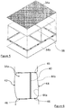
- the floor panels 24, 26a, 26b, 26c, 26d, 28a, 28b, 28c, 28d are made from two parallel outer skin panels 34a, 34b with a floor insulating layer of thermally insulating material 36 therebetween, as illustrated in Figure 5 .
- the skin panels 34a, 34b are made from anti-slip phenolic coated plywood, with the outer skin panels 34a, 34b being arranged such that the anti-slip phenolic coating provides the upper and lower surfaces of each floor panel 24, 26a, 26b, 26c, 26d, 28a, 28b, 28c, 28d.
- the floor insulating layer may be made from a polymer and may have an open or closed cell structure.
- the insulating layer 36 is made from high performance rigid extruded polystyrene insulation.
- the insulating layer 36 may alternatively made from a woven or non-woven fibrous insulating material such as mineral or rock wool, or a felt made from polymeric fibres.
- the outer skins 34a, 34b and insulating layer 36 are mounted in a rectangular frame 38, a substantially fluid tight seal being provided between the frame 38 and the phenolic coatings on the upper and lower surfaces of the outer skin panels 34a, 34b.
- the end walls 20 may be double layered, and comprise two polymeric (e.g. PVC) skin layers with a thermally insulating lining therebetween.
- the thermally insulating lining could be made from a woven or non-woven fibrous material, or from a flexible sheet of polymeric, open or closed-cell foam.
- the thermally insulating lining used in the end walls is a flexible multifoil insulation such as ActisTM Triso Super 10+, which comprises layers of a polymeric fleece or felt sandwiched between thin metal foil.
- the insulating properties of the canopy 14 may be further improved by providing a rib insulating layer 40 of flexible insulating material inside each tubular rib 14a.
- An example of the transverse cross-section through one of the tubular ribs 14a when inflated is illustrated schematically in Figure 5 .
- the rib insulating layer 40 may be made from a thermo-reflective insulation material which comprises at least one reflective foil layer. It may, for example be made from a multfoil insulation in which two or more foil layers are provided either side of an insulating core made of a fibrous material such as glass, rock or mineral wool, or a polymeric bubble insulation.
- a suitable insulation material is ActisTM Triso-Super 10+.
- the ability of the canopy 14 to assist the refrigeration apparatus in maintaining the interior space at the desired low temperature may be further improved by coating the tubular ribs 14a with a blackout coating designed to minimise solar transmission through the tubular ribs 14a, and / or a reflective coating to maximise the reflection of sunlight off the structure 10.
- each tubular rib 14a has an inner skin 42 which encloses the interior space of the structure 10 when the canopy 14 is inflated, and an outer skin 44 which is in contact with environment at the exterior of the structure 10. Together the inner skin 42 and outer skin 44 form a tube with a substantially circular transverse cross-section when inflated.
- the interior surface 44a of the outer skin 44 is coated with a blackout coating, whilst the exterior surface 44b of the outer skin 44 is coated with a coating which maximises the reflection of sunlight off the tubular ribs 14a.
- both sides of the inner skin 42 and outer skin 44 are coated white PVC, whilst an additional blackout coating, which may be a black PVC coating, is provided on the interior surface 44a of the outer skin 44.
- the tubular ribs 14a may be made as follows.
- the inner skin 42 and outer skin 44 are each made from a separate strip of the air impermeable flexible sheet material.
- Each strip may be made from a single piece of the material, but in this embodiment, each strip is made up of a plurality of separate rectangular or square pieces which are connected together, end to end, by hot-air welding.
- Two strips of inner skin 42a, 42b are then placed side by side, and their long edges long edges sewn together with a line of stitching 46 which runs generally parallel to the long edges of the two strips of inner skins 42, 42b.
- the distance between the line of stitching 46 and the adjacent long edge of the strip of inner skin 42a, 42b is greater for one strip than the other.
- Figure 7 shows a schematic illustration of a transverse cross-section through the two adjacent strips of outer skin 44a, 44b.
- the distance between the line of stitching 46 and the adjacent long edge of the first strip of outer skin 44a is less than the distance between the line of stitching 46 and the adjacent long edge of the second strip of outer skin 44b.
- the portion of the second strip of outer skin 44b and the line of stitching 46 will form part of a partition between adjacent tubular ribs 14a, and therefore is hereinafter referred to as the partition strip 48.
- the apertures formed during the stitching process could provide a path for leakage of air out of the tubular ribs 14a, and therefore these are sealed by hot air welding a sealing tape 50 over both sides of the stitching.
- the partition strip 48 is either cut away so that the edge of the second strip of outer skin 44b is generally aligned with the adjacent edge of the first strip of outer skin 44a, or the piece of material used to form the ends of each strip of outer skin 44 is shaped in advance to achieve this result.
- the adjacent ends of all the outer skin strips align to form two opposite tube end edges 58 of the exterior sheet 52, the stitching between the adjacent strips of outer skin 44 extending all the way to the tube edges 58 of the exterior sheet 52. This is illustrated in Figure 10 .
- the rib insulating layers 40 are then stitched onto the sheet 52.
- a strip of the insulating material used to provide the rib insulating layer 40 is placed in each gap between adjacent partition strips 48, and the long edges of each strip of insulating material is stitched to the adjacent partition strips 48. This is illustrated in Figures 8, 9 and 10 .
- each partition strip 48 of the exterior sheet 52 is hot air welded to a corresponding partition strip 48 of the interior sheet 54, as illustrated in Figure 9 .
- the partition strip 48 of the interior sheet 54 may have to be gathered or pleated during this process to provide the tubular ribs 14a with the desired shape, in this example to provide the bends between the side walls 18a, 18b and the roof 20, the ridge 20a of the roof 20 etc.
- tubular ribs 14a are sealed by hot air welding each end edge 58 of the exterior sheet 52 to the adjacent end edge of the interior sheet 54 as illustrated in Figure 11 .
- a piece of sacrificial material may be placed inside to prevent the end edges 58 from becoming welded to other parts of the canopy during this process.
- the strips of inner skin 42 are the same width as the strips of outer skin 44. If the tubular ribs 14a were intended to be secured to a curved edge of floor 12, or to continue round a corner of the floor 12 (for example if the end walls 20 were also formed from tubular ribs 14a), it would be necessary to vary the relative width of the strip of inner skin 42 relative to the width of the strip of outer skin 44 in some or all of the pairs of strips.
- the desired curve in the side walls 18a, 18b could be achieved by making all the strips of inner skin 42 narrower than the strips of outer skin 44.
- the tubular ribs 14a were to continue round a corner, this could be achieved by making the strip of inner skin 42 forming the tubular rib 14a at the corner narrower than the corresponding strip of outer skin 44.
- tubular ribs 14a are sealed by bending the end edge 58 of the exterior sheet 52 and the end edge 58 of the interior sheet 54 towards one another, and hot air welding them together, as illustrated in Figure 11 .
- Either end of each of the end tubes 60 is also sealed by hot air welding the edges of the exterior and interior sheets 52, 54 together.
- the resulting seams may be strengthened by hot air welding a sealing tape along each seam.
- tubular ribs 14a can all be inflated by providing a single air inlet port 15 located in one of the ribs 14a or one of the end tubes 60.
- the stitching 46 By extending the stitching 46 between adjacent strips of inner and outer skin 42, 44 all the way to the end edges 58, the stitching 46 becomes part of the hot air welded seams, and therefore the risk of leakage of air from the tubular ribs 14a where the stitching 46 ends may be reduced.
Landscapes
- Engineering & Computer Science (AREA)
- Architecture (AREA)
- Civil Engineering (AREA)
- Structural Engineering (AREA)
- Physics & Mathematics (AREA)
- Fluid Mechanics (AREA)
- Electromagnetism (AREA)
- Tents Or Canopies (AREA)
- Chemical & Material Sciences (AREA)
- Combustion & Propulsion (AREA)
- Mechanical Engineering (AREA)
- Thermal Sciences (AREA)
- General Engineering & Computer Science (AREA)
- Buffer Packaging (AREA)
Abstract
Description
- The present invention relates to an inflatable structure, particularly, but not exclusively to an insulated inflatable building, and to a method of transporting an inflatable structure.
- It is known to use inflatable structures to provide, temporary buildings for events such as festivals, exhibitions, events or stage shows. Such structures typically comprise a canopy which is formed from a flexible, air impermeable material, which forms a plurality of interconnected tubular ribs. The tubular ribs are connected to a source of compressed air so that they inflate and form arches which support the canopy to provide the roof and walls of the structure. Alternatively, the inflatable structure may have a more conventional shape, having inflatable side walls and a gable or hipped roof, as disclosed in
US200917598 , for example. - It is an object of the present invention to provide a new configuration of inflatable structure, and new method of transporting an inflatable structure, which are particularly suitable for use in providing a temporary cold storage facility. A temporary refrigerated storage facility may, for example, be required for cold storing food or beverages for sale or distribution at a festival, exhibition or event, or for storing food or medicines, for example during aid efforts in disaster zones or impoverished areas.
- According to a first aspect of the invention we provide a structure comprising a floor, and a canopy made from a flexible, substantially air-impermeable material and having at least one tubular rib, the canopy being further provided with an air inlet port by means of which the interior of the tubular ribs can be connected to a source of compressed air, and being movable by the supply of compressed air to the tubular rib via the air inlet port from a collapsed state in which the tubular rib is deflated to an inflated state in which the tubular rib is inflated and supports the canopy in such a way that the canopy encloses an interior space above the floor and forms a roof and side walls of the structure, wherein the floor comprises three substantially rigid floor panels which may be arranged together to form a substantially planar floor, or connected together to form the base and sides of a container in which the canopy can be stored when in the collapsed state.
- Preferably the floor panels are connected together by a hinge mechanism, the hinge mechanism being operable such that the panels can be pivoted relative to one another between an open configuration in which they form a substantially planar floor, and a closed configuration in which they form the base and sides of a container in which the canopy can be stored when in the collapsed state.
- The structure may comprise five rigid floor panels which when in the closed configuration form a base and four sides of the container.
- The rigid floor panels may be substantially square or rectangular and when in the closed configuration form a container which encloses a cuboidal volume.
- The structure may comprise six rigid floor panels which when in the closed configuration for a base, four sides, and a lid of the container.
- The canopy may be secured to the floor panels.
- The structure may comprise canopy fasteners by means of which the canopy may be releasably secured to the periphery of the floor when the floor panels are in their open configuration.
- The structure may comprise a plurality of tubular ribs which are parallel and adjacent to one another and which, when the canopy is in its inflated state form an arch so that the tubular ribs form the roof and two opposite side walls of the structure. In this case, two further opposite side walls, hereinafter referred to as end walls, of the structure may be formed by portions of canopy which do not have inflatable ribs. One or both of the end walls may be releasably connected to the side walls and roof, for example by means of hook and loop fasteners such as Velcro®.
- The structure may further be provided with a pressure sensor which is arranged so as to provide pressure signals indicative of the air pressure in the tubular rib, a processor which is connected to the pressure sensor to receive pressure signals from the pressure sensor, and a source of pressurised air, the processor being programmed to operate initiate supply of pressurised air from the source of pressurised air to the interior of the tubular rib if the pressure in the interior of the tubular rib falls below a pre-determined lower threshold, and to cease the supply of pressurised air from the source of pressurised air to the interior of the tubular rib when the pressure in the interior of the tubular rib reaches a pre-determined upper threshold.
- The structure may further be provided with a pressure relief valve which is configured to allow air to be exhausted from the interior of the tubular rib if the pressure in the interior of the tubular rib falls above a pre-determined upper threshold, and to stop the release of air from the interior of the tubular rib when the pressure in the interior of the tubular rib reaches a pre-determined lower threshold.
- In this case, the structure may further comprise a source of pressurised air, and a pressure operated switch which is configured to initiate supply of pressurised air from the source of pressurised air to the interior of the tubular rib if the pressure in the interior of the tubular rib falls below a second pre-determined lower threshold, and to cease the supply of pressurised air from the source of pressurised air to the interior of the tubular rib when the pressure in the interior of the tubular rib reaches a second pre-determined upper threshold.
- A rib insulating layer may be provided in the interior of each rib.
- The ribs may be made from a flexible polymer sheet.
- The rib insulating layer is advantageously made from a flexible material. It may comprise a polymeric fleece or felt which is sandwiched between two reflective foil layers. The foil layers may be metallic or metal coated foils.
- The canopy may be made from a polymer such as polyvinyl chloride.
- Where provided, the end walls may be double layered, and comprise a polymeric skin with a thermally insulating lining.
- A door may be provided in one of the end panels.
- The floor panels may be made from two parallel outer skin panels with a layer of thermally insulating material therebetween. The skin panels may be made from plywood. The insulating material may be made from a polymer and may have an open or closed cell structure. The insulating material may be made from a woven or non-woven fibrous material.
- The structure may further comprise a refrigeration apparatus which is operable to extract air from the interior space, cool the extracted air, and then return the cooled air to the interior space.
- The structure may be provided with a refrigeration port and a coupling by means of which the refrigeration apparatus may be placed outside the interior space but connected to the interior space so that the refrigeration apparatus can be operated to extract and cool air from the interior space, and return the cooled air to the interior space.
- The floor may have an upper surface which is adjacent the interior space of the structure, and a lower surface which is, when the structure is in use, adjacent the ground, the structure being further provided with at least two support rails which are secured to the lower surface of the floor and which, when the structure is in use, are configured to engage with the ground and support the floor so that it is spaced from the ground. The support rails may be spaced from and parallel to one another.
- Advantageously, at least two support rails are secured to the floor panel which forms the base of the container. More preferably, however, at least two support rails are secured to each floor panel so that each floor panel is supported spaced from the ground by the support rails.
- The support rails may be metallic, and may, for example be made from extruded aluminium.
- The structure may further be provided with container fasteners, such as straps or clips, which are operable to secure the floor panels in the closed configuration, and which are releasable to allow the floor panels to be pivoted to the open configuration.
- According to a second aspect of the invention we provide a method of transporting a structure according to the first aspect of the invention, wherein the method comprises bringing the canopy to its collapsed state, moving the floor panels to their closed configuration, and stowing the canopy in the container formed by the floor panels.
- Where the floor of the structure has an upper surface which is adjacent the interior space of the structure, and a lower surface which is, when the structure is in use, adjacent the ground, and the structure is further provided with at least two support rails which are secured to the lower surface of the floor and which, when the structure is in use, are configured to engage with the ground and support the floor so that it is spaced from the ground, the two support rails being secured to the floor panel which forms the base of the container, the method may further comprise lifting the container and stowed canopy using a vehicle with lifting forks, by moving the lifting forks into the space between the enclosed by the support rails, the ground and the lowermost surface of the floor panel which forms the base of the container, and then moving the lifting forks away from the ground.
- The method according to the second aspect of the invention may comprise the transporting of a structure having any feature or combination of features of the structure according to the first aspect of the invention.
- According to a third aspect of the invention we provide a structure comprising a floor, and a canopy made from a flexible, substantially air-impermeable material and having at least one tubular rib, the canopy being further provided with an air inlet port by means of which the interior of the tubular ribs can be connected to a source of compressed air, and being movable by the supply of compressed air to the tubular rib via the air inlet port from a collapsed state in which the tubular rib is deflated to an inflated state in which the tubular rib is inflated and supports the canopy in such a way that the canopy encloses an interior space above the floor and forms a roof and side walls of the structure, wherein a rib insulating layer is provided in the interior of each rib.
- The ribs may be made from a flexible polymer sheet.
- The rib insulating layer is advantageously made from a flexible material. It may comprise a polymeric fleece or felt which is sandwiched between two reflective foil layers. The foil layers may be metallic or metal coated foils.
- Each tubular rib may have an interior skin which faces the interior space enclosed by the canopy, and an exterior skin which faces the exterior of the structure, the space between the interior skin and exterior skin forming the interior of the tubular rib, the exterior surface of the exterior skin being provided with reflective coating.
- The interior surface of the exterior skin may be provided with a coating to reduce transmission of solar energy through the exterior skin into the interior of the tubular rib.
- The structure may further be provided with a pressure sensor which is arranged so as to provide pressure signals indicative of the air pressure in the tubular rib, a processor which is connected to the pressure sensor to receive pressure signals from the pressure sensor, and a source of pressurised air, the processor being programmed to operate initiate supply of pressurised air from the source of pressurised air to the interior of the tubular rib if the pressure in the interior of the tubular rib falls below a pre-determined lower threshold, and to cease the supply of pressurised air from the source of pressurised air to the interior of the tubular rib when the pressure in the interior of the tubular rib reaches a pre-determined upper threshold.
- The structure may further be provided with a pressure relief valve which is configured to allow air to be exhausted from the interior of the tubular rib if the pressure in the interior of the tubular rib falls above a pre-determined upper threshold, and to stop the release of air from the interior of the tubular rib when the pressure in the interior of the tubular rib reaches a pre-determined lower threshold.
- In this case, the structure may further comprise a source of pressurised air, and a pressure operated switch which is configured to initiate supply of pressurised air from the source of pressurised air to the interior of the tubular rib if the pressure in the interior of the tubular rib falls below a second pre-determined lower threshold, and to cease the supply of pressurised air from the source of pressurised air to the interior of the tubular rib when the pressure in the interior of the tubular rib reaches a second pre-determined upper threshold.
- According to a fourth aspect of the invention we provide a structure comprising a floor, and a canopy made from a flexible, substantially air-impermeable material and having at least one tubular rib, the canopy being further provided with an air inlet port by means of which the interior of the tubular ribs can be connected to a source of compressed air, and being movable by the supply of compressed air to the tubular rib via the air inlet port from a collapsed state in which the tubular rib is deflated to an inflated state in which the tubular rib is inflated and supports the canopy in such a way that the canopy encloses an interior space above the floor and forms a roof and side walls of the structure, wherein the structure is further provided with a pressure sensor which is arranged so as to provide pressure signals indicative of the air pressure in the tubular rib, a processor which is connected to the pressure sensor to receive pressure signals from the pressure sensor, and a source of pressurised air, the processor being programmed to operate initiate supply of pressurised air from the source of pressurised air to the interior of the tubular rib if the pressure in the interior of the tubular rib falls below a pre-determined lower threshold, and to cease the supply of pressurised air from the source of pressurised air to the interior of the tubular rib when the pressure in the interior of the tubular rib reaches a pre-determined upper threshold.
- According to a fifth aspect of the invention we provide a structure comprising a floor, and a canopy made from a flexible, substantially air-impermeable material and having at least one tubular rib, the canopy being further provided with an air inlet port by means of which the interior of the tubular ribs can be connected to a source of compressed air, and being movable by the supply of compressed air to the tubular rib via the air inlet port from a collapsed state in which the tubular rib is deflated to an inflated state in which the tubular rib is inflated and supports the canopy in such a way that the canopy encloses an interior space above the floor and forms a roof and side walls of the structure, wherein the structure is further provided with a pressure relief valve which is configured to allow air to be exhausted from the interior of the tubular rib if the pressure in the interior of the tubular rib falls above a pre-determined upper threshold, and to stop the release of air from the interior of the tubular rib when the pressure in the interior of the tubular rib reaches a pre-determined lower threshold.
- In this case, the structure may further comprise a source of pressurised air, and a pressure operated switch which is configured to initiate supply of pressurised air from the source of pressurised air to the interior of the tubular rib if the pressure in the interior of the tubular rib falls below a second pre-determined lower threshold, and to cease the supply of pressurised air from the source of pressurised air to the interior of the tubular rib when the pressure in the interior of the tubular rib reaches a second pre-determined upper threshold.
- Embodiments of the invention will now be described, by way of example only, with reference to the following figures, of which,
-
FIGURE 1 is a perspective view of a structure according to the first, third, fourth and fifth aspect of the invention with the floor panels in their open configuration and the canopy in its inflated state, -
FIGURE 2 is a perspective view of the structure illustrated inFigure 1 with the end walls removed to show the interior of the structure, -
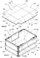
FIGURE 3 is a perspective view of the floor of the structure illustrated inFigure 1 with the floor panels in their open configuration, -
FIGURE 4 is a perspective view of the floor of the structure illustrated inFigure 1 with the floor panels in their closed configuration, -
FIGURE 5 is an exploded view of one of the floor panels illustrated inFigures 2 and3 , -
FIGURE 6 is a schematic illustration of the transverse cross-section through one of the tubular ribs of the structure illustrated inFigure 1 , -
FIGURE 7 is a transverse cross-section through a portion of the join between two adjacent tubular ribs of the structure illustrated inFigure 1 , -
FIGURE 8 is a perspective view of a transverse cross-section through a plurality of outer strips joined to form an exterior sheet for the canopy of the structure illustrated inFigure 1 , -
FIGURE 9 is a perspective view of a transverse cross-section through a portion of the exterior sheet and interior sheet joined to form tubular ribs of the canopy of the structure illustrated inFigure 1 , -
FIGURE 10 is a perspective view of an edge of the exterior sheet illustrated inFigure 8 , and -
FIGURE 11 is a side view of a longitudinal cross-section of an end portion of one of the tubular ribs of the canopy of the structure illustrated inFigure 1 . - Referring now to
Figure 1 , there is shown astructure 10 comprising afloor 12, and acanopy 14 made from a flexible, substantially air-impermeable material, and having a plurality oftubular ribs 14a. Thecanopy 14 is advantageously made from a polymer, for example comprising polyvinyl chloride (PVC). Specifically, in this example, thecanopy 14 is made from a woven polyester base cloth which is coated on both sides with a PVC coating to provide the necessary impermeability. A top coating of lacquer may also be present to protect the PVC coating and to improve the ease of cleaning of the structure. Examples of suitable materials are the Valmex® products made by Low & Bonar GmbH company, Mehler Texnologies. - The
canopy 14 is further provided with anair inlet port 15 by means of which the interior of thetubular ribs 14a can be connected to a source of compressed air such as a pump. Thecanopy 14 is movable by the supply of compressed air to thetubular ribs 14a via theair inlet port 15 from a collapsed state, in which thetubular ribs 14a are deflated, to an inflated state in which thetubular ribs 14a are inflated and supports thecanopy 14 in such a way that thecanopy 14 encloses an interior space above thefloor 12 and forms aroof 16 andside walls structure 10. - In this example, the
canopy 14 is provided with sixtubular ribs 14a, but it will be appreciated that this need not be the case, and more or fewer than six could be provided depending on the size and shape of the structure. In this example, the tubular ribs are parallel and adjacent to one another and extend from oneedge 12a of thefloor 12 to anopposite edge 12b of thefloor 12. They are configured such that, when thecanopy 14 is in its inflated state, they form an arch which extends over thefloor 12, from thefirst edge 12a of thefloor 12 to the second, opposite,edge 12b of thefloor 12. Consequently, thetubular ribs 14a form theroof 16 and twoopposite side walls 18a, 18b of the structure. In this example, thetubular ribs 14a are shaped such that they extend upwardly from theedges floor 12, generally perpendicular to the floor, so as to formside walls 18a, 18b which are generally planar and lie generally perpendicular to thefloor 12. Theroof 16 comprises a ridge 16a, which lies generally centrally between the twoside walls 18a, 18b, and four generally planar inclined portions - two on either side of the ridge 16a. It should be appreciated that this need not be the case, however. Thetubular ribs 14a, could, for example, be configured to provide two planar, upright side walls, whilst theroof 16 is curved, or tubular ribs form a continuous, parabolic arch so that both the side walls and roof are curved. Thetubular ribs 14a need not extend all the way from oneedge 12a of thefloor 12 to theopposite edge 12b of the floor. For example, oneside wall 18a and the adjacent half of theroof 20 may be formed from a first set oftubular ribs 14a, whilst the other side wall 18b and the other half of theroof 20 are formed from a second set of thetubular rib 14a, the two sets oftubular ribs 14a being connected at the ridge 16a of theroof 16. Alternatively, the tubular ribs could lie generally parallel to thefloor 12 and be stacked in a generally vertical stack to form the side walls - Although the two further
opposite side walls 20, hereinafter referred to asend walls 20, of thestructure 10 may also containtubular ribs 14a, in this case, they are formed by portions ofcanopy 14 which do not have inflatable ribs. Theend walls 20 are releasably connected to theside walls 18a, 18b androof 20, in this example by means of hook and loop fasteners such as Velcro®. - In this embodiment, the
tubular ribs 14a at each end of the enclosure (directly adjacent the end walls 20) have a significantly larger diameter, than theother ribs 14a to assist in supporting theend walls 20. This is illustrated inFigure 2 . - One of the
end walls 20 is provided with adoorway 22 to provide an entrance whereby a person can enter the interior space of thestructure 10. In this example the doorway is a generally rectangular aperture which is closed by means of two generallyrectangular doors 22a, 22b which are formed from the same flexible, air impermeable material as the rest of theend wall 20. - In this example, first edge of each
door 22a, 22b is pivotally connected to one of two vertical edges of thedoorway 20. Fasteners, in this example hook and loop fasteners, are provided to secure top horizontal edges of the doors to a top horizontal edge of thedoorway 22, and to secure a second vertical edge onedoor 22a to a second, vertical, edge of the other door 22b. In this example, eachdoor 22a, 22b is integral with the remainder of theend wall 20. - The
doorway 22 could, however, be a simple vertical slit in theend wall 20. - The
floor 12 is shown in more detail inFigures 3, 4 and5 . - The
floor 12 comprises a plurality of interconnected substantiallyrigid floor panels panels Figure 3 , and a closed configuration in which they form the base and sides of a container, as illustrated inFigure 4 . - The
floor 12 has an upper surface which, when thefloor panels structure 10, and a lower surface which, when the structure is in use, is adjacent the ground. The upper surface of thefloor 12 therefore forms the interior surface of the container when thefloor panels adjacent floor panels adjacent floor panels floor 12 is as smooth as possible, and the risk of a person moving round the interior space of the structure tripping over the hinge mechanism or part of the hinge mechanism is eliminated. This need not be the case, however, and a non-concealed hinge mechanism, which lies on and protrudes from the uppermost surface of thefloor 12, could be used instead. - In this example, the structure comprises five
rigid floor panels rigid floor panels - To achieve this, in this embodiment, one edge of each of the
floor panels side floor panels floor panel 24 which forms the base of the container (hereinafter referred to as the base floor panel 24). It will be appreciated that, when pivoted to the open configuration, the resultingfloor 12 would form the shape of a cross. - In order to provide a substantially
rectangular floor 12, in this embodiment, in addition to the fiverectangular floor panels additional floor panels side floor panels additional floor panels side floor panels additional floor panels floor panels additional floor panels floor 12. This is provided to accommodate the enlargedtubular ribs 14a adjacent theend walls 20 of thestructure 10 as illustrated inFigure 2 . - In this embodiment, the
side floor panels end panels base panel 24, and twoside panels base panel 24. Two of theadditional panels end panels 26a, and the other twoadditional panels end panels 26c. When thefloor panels additional floor panels side panels 26b, while the other two of theadditional panels side panels 26d. - Although not shown in this example, the structure may comprise a further rigid floor panel which, when the
floor panels - The structure may further be provided with container fasteners, such as straps, clips, latches or slide bolts, which are operable to secure the
floor panels floor panels side panels side panels - When in the collapsed state, i.e. when the
ribs 14a are deflated, thecanopy 14 can be folded or rolled up and stored in the container formed by thefloor panels canopy 14 is particularly vulnerable to being damaged to such an extent that thestructure 10 no longer functions, as any hole or tear in thetubular ribs 14a will cause air to escape from thetubular ribs 14a when they are inflated. This could mean that air pressure in the ribs cannot reach a sufficiently high pressure for theribs 14a to support thecanopy 14 in the inflated state, or could cause the canopy to collapse over time from the inflated state. As such, it is important to protect thecanopy 14 from damage during its storage or transportation. By using thefloor 12 to as a rigid container for thecanopy 14, thecanopy 14 may be protected from damage, without the need to provide a separate crate, or container. As such, cost may be saved in storing and / or transporting the structure, as the weight and volume of the items to be stored and / or transported can be reduced. - The
canopy 14 may be secured to thefloor panels canopy 12 may be secured to the outer edges of theside floor panels additional floor panels floor 12. - The
canopy 14 may be permanently secured to thefloor panels floor panels planar floor 12, thestructure 10 is ready to erect by inflating thetubular ribs 14a. Alternatively, releasable canopy fasteners such as clips or hook and loop fasteners may be provided to secure thecanopy 14 to thefloor 12 when thefloor panels canopy 14 from thefloor 12 before folding thefloor 12 and stowing thecanopy 14 in the container formed by the foldedfloor panels floor panels canopy 14 in the container with thecanopy 14 still attached to thefloor 12. - In this embodiment of the invention, the structure is further provided with a plurality of support rails 30, 32 which are secured to the lower surface of the
floor 12 and which, when thestructure 10 is in use, are configured to engage with the ground and support thefloor 12 so that it is spaced from the ground. In this example, threesupport rails 30 which are spaced from and parallel to one another are mounted on the lower surface of each of thebase floor panel 24 and fourside floor panels additional floor panels side floor panels floor 12 is folded up, as illustrated inFigure 3 , an end of each of the support rails 32 for theadditional floor panels side floor panel floor panels side 26b, 26c, 26d to which they are connected to engage with and support the lower surface of thefloor panel 26aadditional floor panels - The support rails may be metallic, and may, for example be made from extruded aluminium.
- The support rails 30 may reinforce and assist in strengthening the
floor 12 and the container formed thefloor panels - The support rails 30 on the
side floor panels base panel 24 to which theside panel side floor panels side floor panels floor panels - To further strengthen the container, the support rails 30 on the
side floor panels floor panels support rail 30 is directly adjacent to an end of asupport rail 30 on an adjacentside floor panel support rail 30 with the end of theadjacent support rail 30 on theadjacent side panel floor panels - Moreover, in spacing the
base panel 24 from the ground when thefloor panels - Once the
tubular ribs 14a have been inflated to the desired pressure, the source of compressed air may be detached from theair inlet port 15, and theair inlet port 15 plugged. However, it is likely that, over time, the air pressure in thetubular ribs 14a will not stay at the desired level. There may be points at which air can leak slowly out of thetubular ribs 14a so that the air pressure therein reduces slowly over time until thestructure 10 collapses. To reduce the risk of this occurring, thestructure 10 may be further provided with a pressure return monitoring system (hereinafter referred to as a PRMS) which operates automatically to maintain the air pressure in thetubular ribs 14a between predetermined limits. - The PRMS may comprise a settable pressure activated switch, and an electrically operated air blower or pump or other source of pressurised air (such as a compressed air cylinder). The air blower / source of pressurised air may be connected to the interior of the
tubular ribs 14a via a non-return valve and theair inlet port 15, or by an alternative inflation inlet port (not shown). The pressure switch is connected to the interior of thetubular ribs 14a via a separate, smaller diameter flexible tube (such as a tube 6 mm in diameter), and is configured such that when activated by pressure in thetubular ribs 14a exceeding a predetermined upper pressure threshold, it closes an electrical contact, and opens the electrical contact when the pressure in thetubular ribs 14a falls below a predetermined lower pressure threshold. Where an air blower or pump is provided, the electrical contact is connected to the air blower such that when the contact is closed, the air blower operates to blow more air into the interior of thetubular ribs 14a, and when the contact is open, the air blower does not operate. Alternatively, the electrical contact may be connected to an electrically operable valve provided in the connection between the source of pressurised air and the interior of the tubular rib, so that when the contact is closed, the valve operates to allow flow of air from the source of pressurised air, into the interior of thetubular rib 14a, and when the contact is open, closes the valve to prevent flow of air from the source of pressurised air into the interior of thetubular rib 14. - Alternatively, an electronic PRMS may be provided, comprising an electronic pressure sensor, an electrical switch, and an electrically operated air blower or pump or other source of pressurised air (such as a compressed air cylinder). Again, the air blower / source of pressurised air may be connected to the interior of the
tubular ribs 14a via a non-return valve and theair inlet port 15, or by an alternative inflation inlet port (not shown). The pressure sensor is connected to the interior of thetubular ribs 14a via a separate, smaller diameter flexible tube (such as a tube 6 mm in diameter). Where an air blower or pump is provided, the switch is connected to the air blower such that when the switch is closed, the air blower operates to blow more air into the interior of thetubular ribs 14a, and when the switch is open, the air blower does not operate. Alternatively, the switch may be connected to an electrically operable valve provided in the connection between the source of pressurised air and the interior of the tubular rib, so that when the switch is closed, the valve operates to allow flow of air from the source of pressurised air, into the interior of thetubular rib 14a, and when open closes the valve to prevent flow of air from the source of pressurised air into the interior of thetubular rib 14. - The switch receives a signal from the pressure sensor which represents the air pressure in the
tubular ribs 14a, and is configured to close the switch when the signal from the pressure sensor indicates that the air pressure in thetubular ribs 14a has fallen below a predetermined lower threshold level, and to open the switch when the pressure in thetubular ribs 14a reaches a pre-determined higher threshold level. This may be achieved by connecting the electronic pressure sensor and switch to an appropriately programmed electronic control unit. In this case, the electronic control unit may comprise a user input device such as a key pad or touch screen, by means of which a user may change the programmed upper and lower threshold levels. - When inflatable structures such as this are used in a hot and / or sunny environment, increases in the temperature of the
tubular ribs 14a can cause the air inside thetubular ribs 14a to expand. In fact, there may be sufficient expansion of the air inside thetubular ribs 14a that the air pressure in thetubular ribs 14a reaches sufficiently high levels that it damages thestructure 10, for example by causing one or more of thetubular ribs 14a to tear at one or more of its seams. In this case, it may be desirable to include one or more pressure relief valves by means of which air can be exhausted from thetubular ribs 14a. The pressure relief valve could be mechanically operated, and set to open when the pressure in thetubular ribs 14a exceeds a pre-set level which is slightly higher than the normal operating pressure. For example, this may be a one-way valve with a valve member which is biased to a closed position by means of a spring, and which opens when the force exerted on the valve member by the air pressure inside thetubular ribs 14a is sufficient to overcome the biasing force of the spring. - Alternatively, where the structure is provided with an electronic PRMS as described above, the or each pressure relief valve could be an electrically operable quick release valve which is incorporated in the PRMS, and the PRMS being configured to open the quick release valve to release air from the interior of the
tubular ribs 14a if the pressure detected by the pressure sensor exceeds a pre-determined limit (which is slightly higher than the normal upper threshold level used to trigger the opening of the switch), and then to close the quick release valve when the pressure detected by the pressure sensor falls below a pre-determined level (which is between the upper and lower threshold level used in triggering the opening or closing of the switch). - For redundancy purposes, in case the PRMS fails, the
structure 10 may be provided with a second PRMS, and/or back-up mechanical pressure relief valves. - In order to be used as a temporary cold storage facility, the
structure 10 may further comprise a refrigeration apparatus (not shown) which is operable to extract air from the interior space, cool the extracted air, and then return the cooled air to the interior space. In this case, the structure is advantageously provided with a refrigeration port and a coupling by means of which the refrigeration apparatus may be placed outside the interior space but connected to the interior space so that the refrigeration apparatus can be operated to extract and cool air from the interior space, and return the cooled air to the interior space. In this example, the refrigeration port is provided in the opposite end wall to theend wall 20 in which thedoorway 22 is provided. - In order to ensure that air as much as possible of the air from the interior space that passes through the refrigeration port enters the refrigeration unit, the end wall around the refrigeration port may be provided with a sealing arrangement to secure the end wall to the refrigeration unit, and ensure a substantially air tight seal between the two. This sealing arrangement may comprise mechanical clips and / or hook and look fasteners.
- The
floor panels structure 10 and refrigeration unit, which could be particular advantageous when it is to be shipped to a remote location, for example for use in disaster relief. - Where the
structure 10 is intended for use as a temporary cold storage facility, thestructure 10 is advantageously insulated to minimise the load on the refrigeration apparatus and assist in maintaining the interior space at the desired low temperature. - For example, in one embodiment, the
floor panels outer skin panels Figure 5 . In this example, theskin panels outer skin panels floor panel floor 12. In one example, the insulating layer 36 is made from high performance rigid extruded polystyrene insulation. The insulating layer 36 may alternatively made from a woven or non-woven fibrous insulating material such as mineral or rock wool, or a felt made from polymeric fibres. - The insulating nature of the
floor 12, combined with the elevation of thefloor 12 above the ground by the support rails 30,32 may prevent the ground below thestructure 10 from being damaged by the lower temperature of the air in the interior space of thestructure 10. - In order to protect the plywood and insulating layer from damage caused by moisture, the
outer skins rectangular frame 38, a substantially fluid tight seal being provided between theframe 38 and the phenolic coatings on the upper and lower surfaces of theouter skin panels - Additionally or alternatively, the
end walls 20 may be double layered, and comprise two polymeric (e.g. PVC) skin layers with a thermally insulating lining therebetween. The thermally insulating lining could be made from a woven or non-woven fibrous material, or from a flexible sheet of polymeric, open or closed-cell foam. In one embodiment, the thermally insulating lining used in the end walls is a flexible multifoil insulation such as Actis™ Triso Super 10+, which comprises layers of a polymeric fleece or felt sandwiched between thin metal foil. - The use of air filled tubular ribs in the
roof 16 andside walls 18a, 18b assists in thermally insulating the interior space. The insulating properties of thecanopy 14 may be further improved by providing arib insulating layer 40 of flexible insulating material inside eachtubular rib 14a. An example of the transverse cross-section through one of thetubular ribs 14a when inflated is illustrated schematically inFigure 5 . - The
rib insulating layer 40 may be made from a thermo-reflective insulation material which comprises at least one reflective foil layer. It may, for example be made from a multfoil insulation in which two or more foil layers are provided either side of an insulating core made of a fibrous material such as glass, rock or mineral wool, or a polymeric bubble insulation. An example of a suitable insulation material is Actis™ Triso-Super 10+. - Alternatively or additionally, the ability of the
canopy 14 to assist the refrigeration apparatus in maintaining the interior space at the desired low temperature may be further improved by coating thetubular ribs 14a with a blackout coating designed to minimise solar transmission through thetubular ribs 14a, and / or a reflective coating to maximise the reflection of sunlight off thestructure 10. - As illustrated in
Figure 6 , eachtubular rib 14a has aninner skin 42 which encloses the interior space of thestructure 10 when thecanopy 14 is inflated, and anouter skin 44 which is in contact with environment at the exterior of thestructure 10. Together theinner skin 42 andouter skin 44 form a tube with a substantially circular transverse cross-section when inflated. Preferably theinterior surface 44a of theouter skin 44 is coated with a blackout coating, whilst theexterior surface 44b of theouter skin 44 is coated with a coating which maximises the reflection of sunlight off thetubular ribs 14a. As a result solar reflection off the exterior surface of theouter skin 44 of thetubular ribs 42 may be enhanced, and solar transmission through theouter skin 44 may be reduced, and therefore solar heating of the air inside thetubular ribs 14a, and hence also the air in the interior space of thestructure 10, may be reduced. - In this embodiment, both sides of the
inner skin 42 andouter skin 44 are coated white PVC, whilst an additional blackout coating, which may be a black PVC coating, is provided on theinterior surface 44a of theouter skin 44. - The
tubular ribs 14a may be made as follows. Theinner skin 42 andouter skin 44 are each made from a separate strip of the air impermeable flexible sheet material. Each strip may be made from a single piece of the material, but in this embodiment, each strip is made up of a plurality of separate rectangular or square pieces which are connected together, end to end, by hot-air welding. Two strips of inner skin 42a, 42b are then placed side by side, and their long edges long edges sewn together with a line ofstitching 46 which runs generally parallel to the long edges of the two strips ofinner skins 42, 42b. - The distance between the line of
stitching 46 and the adjacent long edge of the strip of inner skin 42a, 42b is greater for one strip than the other. This is illustrated inFigure 7 , which shows a schematic illustration of a transverse cross-section through the two adjacent strips ofouter skin stitching 46 and the adjacent long edge of the first strip ofouter skin 44a is less than the distance between the line ofstitching 46 and the adjacent long edge of the second strip ofouter skin 44b. The portion of the second strip ofouter skin 44b and the line ofstitching 46 will form part of a partition between adjacenttubular ribs 14a, and therefore is hereinafter referred to as thepartition strip 48. - The apertures formed during the stitching process could provide a path for leakage of air out of the
tubular ribs 14a, and therefore these are sealed by hot air welding a sealingtape 50 over both sides of the stitching. - This process is then repeated for all the strips of
outer skin 44 required to form thetubular ribs 14a of thestructure 10, to create aexterior sheet 52 which will form the exterior facing surface of theroof 16 andside walls 18a, 18b of thestructure 10, as illustrated inFigure 8 . - At the ends of the strips of
outer skin 44, thepartition strip 48 is either cut away so that the edge of the second strip ofouter skin 44b is generally aligned with the adjacent edge of the first strip ofouter skin 44a, or the piece of material used to form the ends of each strip ofouter skin 44 is shaped in advance to achieve this result. The adjacent ends of all the outer skin strips align to form two opposite tube end edges 58 of theexterior sheet 52, the stitching between the adjacent strips ofouter skin 44 extending all the way to the tube edges 58 of theexterior sheet 52. This is illustrated inFigure 10 . - Where provided, the
rib insulating layers 40 are then stitched onto thesheet 52. To achieve this, a strip of the insulating material used to provide therib insulating layer 40 is placed in each gap between adjacent partition strips 48, and the long edges of each strip of insulating material is stitched to the adjacent partition strips 48. This is illustrated inFigures 8, 9 and10 . - The same process is repeated with the
inner skins 42 to create aninterior sheet 54 which will form the interior facing surface of theroof 16 andside walls 18a, 18b of thestructure 10. In this case, however, no insulating material is stitched to the partition strips 48. - To form the
tubular ribs 14a, eachpartition strip 48 of theexterior sheet 52 is hot air welded to acorresponding partition strip 48 of theinterior sheet 54, as illustrated inFigure 9 . Thepartition strip 48 of theinterior sheet 54 may have to be gathered or pleated during this process to provide thetubular ribs 14a with the desired shape, in this example to provide the bends between theside walls 18a, 18b and theroof 20, the ridge 20a of theroof 20 etc. - Finally, the ends of the
tubular ribs 14a are sealed by hot air welding eachend edge 58 of theexterior sheet 52 to the adjacent end edge of theinterior sheet 54 as illustrated inFigure 11 . A piece of sacrificial material may be placed inside to prevent the end edges 58 from becoming welded to other parts of the canopy during this process. - In this case, as the
tubular ribs 14a are intended to form substantiallyplanar side walls 18a, 18b and sections ofroof 20, the strips ofinner skin 42 are the same width as the strips ofouter skin 44. If thetubular ribs 14a were intended to be secured to a curved edge offloor 12, or to continue round a corner of the floor 12 (for example if theend walls 20 were also formed fromtubular ribs 14a), it would be necessary to vary the relative width of the strip ofinner skin 42 relative to the width of the strip ofouter skin 44 in some or all of the pairs of strips. For example, if the outer periphery of thefloor 12 were circular, the desired curve in theside walls 18a, 18b could be achieved by making all the strips ofinner skin 42 narrower than the strips ofouter skin 44. Similarly, if thetubular ribs 14a were to continue round a corner, this could be achieved by making the strip ofinner skin 42 forming thetubular rib 14a at the corner narrower than the corresponding strip ofouter skin 44. - Finally, the
tubular ribs 14a are sealed by bending theend edge 58 of theexterior sheet 52 and theend edge 58 of theinterior sheet 54 towards one another, and hot air welding them together, as illustrated inFigure 11 . This results in the formation of a twoend tubes 60 which extend perpendicular to thetubular ribs 14a and lie at either end thereof. Either end of each of theend tubes 60 is also sealed by hot air welding the edges of the exterior andinterior sheets - The space between the
exterior sheet 52 andinterior sheet 54 is therefore completely sealed, the interiors of thetubular ribs 14a being connected by the twoend tubes 60. This means that thetubular ribs 14a can all be inflated by providing a singleair inlet port 15 located in one of theribs 14a or one of theend tubes 60. - By extending the
stitching 46 between adjacent strips of inner andouter skin stitching 46 becomes part of the hot air welded seams, and therefore the risk of leakage of air from thetubular ribs 14a where thestitching 46 ends may be reduced.
Claims (15)
- A structure (10) comprising a floor (12), and a canopy (14) made from a flexible, substantially air-impermeable material and having at least one tubular rib (14a), the canopy (14) being further provided with an air inlet port (15) by means of which the interior of the tubular rib (14a) can be connected to a source of compressed air, and being movable by the supply of compressed air to the tubular rib (14a) via the air inlet port from a collapsed state in which the tubular rib (14a) is deflated to an inflated state in which the tubular rib (14a) is inflated and supports the canopy (14) in such a way that the canopy (14) encloses an interior space above the floor (12) and forms a roof (16) and side walls (18a, 18b) of the structure (10), characterised in that the floor (12) comprises three substantially rigid floor panels (24, 26a, 26b, 26c, 26d) which may be arranged together to form a substantially planar floor (12), or connected together to form the base and sides of a container in which the canopy (14) can be stored when in the collapsed state.
- A structure (10) according to claim 1 wherein the floor panels (24, 26a, 26b, 26c, 26d) are made from two parallel outer skin panels (34a, 34b) with a layer of thermally insulating material (36) therebetween.
- A structure (10) according to any preceding claim further comprising a refrigeration apparatus which is operable to extract air from the interior space, cool the extracted air, and then return the cooled air to the interior space.
- A structure (10) according to claim 3 further provided with a refrigeration port and a coupling by means of which the refrigeration apparatus may be placed outside the interior space but connected to the interior space so that the refrigeration apparatus can be operated to extract and cool air from the interior space, and return the cooled air to the interior space.
- A structure (10) according to any preceding claim wherein the floor (12) has an upper surface (34a) which is adjacent the interior space of the structure, and a lower surface (34b) which is, when the structure (10) is in use, adjacent the ground, the structure (10) being further provided with at least two support rails (30, 32) which are secured to the lower surface (34b) of the floor (12) and which, when the structure (10) is in use, are configured to engage with the ground and support the floor (12) so that it is spaced from the ground.
- A structure (10) according to claim 5 wherein at least two support rails (30, 32) are secured to the floor panel (24) which forms the base of the container.
- A structure according to claim 5 or 6 wherein at least two support rails (30, 32) are provided for each floor panel (24, 26a, 26b, 26c, 26d) so that each floor panel (24, 26a, 26b, 26c, 26d) is supported spaced from the ground by the support rails (30, 32) when in the open position.
- A method of transporting a structure (10) according to any preceding claim wherein the method comprises bringing the canopy (14) to its collapsed state, moving the floor panels (24, 26a, 26b, 26c, 26d) to their closed configuration, and stowing the canopy (14) in the container formed by the floor panels (24, 26a, 26b, 26c, 26d).
- A method according to claim 8, wherein the floor (12) of the structure (10) has an upper surface (34a) which is adjacent the interior space of the structure (10), and a lower surface (34b) which is, when the structure is in use, adjacent the ground, the structure (10) being further provided with at least two support rails (30, 32) which are secured to the lower surface (34b) of the floor (12) and which, when the structure (10) is in use, are configured to engage with the ground and support the floor (12) so that it is spaced from the ground, the two support rails (30, 32) being secured to the floor panel (24) which forms the base of the container, the method further comprising lifting the container and stowed canopy (14) using a vehicle with lifting forks, by moving the lifting forks into the space between the enclosed by the support rails (30, 32), the ground and the lowermost surface (34b) of the floor panel (24) which forms the base of the container, and then moving the lifting forks away from the ground.
- A structure (10) comprising a floor (12), and a canopy (14) made from a flexible, substantially air-impermeable material and having at least one tubular rib (14a), the canopy (14) being further provided with an air inlet port by means of which the interior of the tubular rib (14a) can be connected to a source of compressed air, and being movable by the supply of compressed air to the tubular rib (14a) via the air inlet port from a collapsed state in which the tubular rib (14a) is deflated to an inflated state in which the tubular rib (14a) is inflated and supports the canopy (14) in such a way that the canopy (14) encloses an interior space above the floor (12) and forms a roof (16) and side walls (18a, 18b) of the structure, wherein a rib insulating layer (40) is provided in the interior of each rib (14a).
- A structure according to claim 10 wherein each tubular rib (14a) has an interior skin (42) which faces the interior space enclosed by the canopy (14), and an exterior skin (44) which faces the exterior of the structure, the space between the interior skin (42) and exterior skin (44) forming the interior of the tubular rib (14a), the exterior surface (44b) of the exterior skin (44) being provided with reflective coating.
- A structure according to claim 11 wherein the interior surface (44a) of the exterior skin (44) is provided with a coating to reduce transmission of solar energy through the exterior skin (44) into the interior of the tubular rib (14a).
- A structure (10) comprising a floor (12), and a canopy (14) made from a flexible, substantially air-impermeable material and having at least one tubular rib (14a), the canopy (14) being further provided with an air inlet port by means of which the interior of the tubular rib (14a) can be connected to a source of compressed air, and being movable by the supply of compressed air to the tubular rib (14a) via the air inlet port from a collapsed state in which the tubular rib (14a) is deflated to an inflated state in which the tubular rib (14a) is inflated and supports the canopy (14) in such a way that the canopy (14) encloses an interior space above the floor (12) and forms a roof (16) and side walls (18a, 18b) of the structure (10), wherein the structure (10) is further provided with a pressure activated switch which is reacts to the air pressure in the tubular rib (14a), and a source of pressurised air, the pressure activated switch being configured to operate to initiate supply of pressurised air from the source of pressurised air to the interior of the tubular rib (14a) if the pressure in the interior of the tubular rib (14b) falls below a pre-determined lower threshold, and to cease the supply of pressurised air from the source of pressurised air to the interior of the tubular rib (14a) when the pressure in the interior of the tubular rib (14a) reaches a pre-determined upper threshold.
- A structure (10) comprising a floor (12), and a canopy (14) made from a flexible, substantially air-impermeable material and having at least one tubular rib (14a), the canopy (14) being further provided with an air inlet port by means of which the interior of the tubular rib (14a) can be connected to a source of compressed air, and being movable by the supply of compressed air to the tubular rib (14a) via the air inlet port from a collapsed state in which the tubular rib (14a) is deflated to an inflated state in which the tubular rib (14a) is inflated and supports the canopy (14) in such a way that the canopy (14) encloses an interior space above the floor (12) and forms a roof (16) and side walls (18a, 18b) of the structure (10), wherein the structure is further provided with a pressure relief valve which is configured to allow air to be exhausted from the interior of the tubular rib (14a) if the pressure in the interior of the tubular rib (14a) falls above a pre-determined upper threshold, and to stop the release of air from the interior of the tubular rib (14a) when the pressure in the interior of the tubular rib (14a) reaches a pre-determined lower threshold.
- A structure according to claim 14 further comprising a source of pressurised air, and a pressure operated switch which is configured to initiate supply of pressurised air from the source of pressurised air to the interior of the tubular rib (14a) if the pressure in the interior of the tubular rib (14a) falls below a second pre-determined lower threshold, and to cease the supply of pressurised air from the source of pressurised air to the interior of the tubular rib (14a) when the pressure in the interior of the tubular rib reaches a second pre-determined upper threshold.
Applications Claiming Priority (1)
| Application Number | Priority Date | Filing Date | Title |
|---|---|---|---|
| GB2000525.2A GB2591096B (en) | 2020-01-14 | 2020-01-14 | An inflatable structure and method of transporting an inflatable structure |
Publications (3)
| Publication Number | Publication Date |
|---|---|
| EP3875711A2 true EP3875711A2 (en) | 2021-09-08 |
| EP3875711A3 EP3875711A3 (en) | 2021-10-27 |
| EP3875711B1 EP3875711B1 (en) | 2025-05-21 |
Family
ID=69626419
Family Applications (1)
| Application Number | Title | Priority Date | Filing Date |
|---|---|---|---|
| EP21151026.8A Active EP3875711B1 (en) | 2020-01-14 | 2021-01-11 | An inflatable structure |
Country Status (6)
| Country | Link |
|---|---|
| US (1) | US11946274B2 (en) |
| EP (1) | EP3875711B1 (en) |
| ES (1) | ES3037488T3 (en) |
| GB (1) | GB2591096B (en) |
| PL (1) | PL3875711T3 (en) |
| PT (1) | PT3875711T (en) |
Families Citing this family (12)
| Publication number | Priority date | Publication date | Assignee | Title |
|---|---|---|---|---|
| EP3763654A1 (en) * | 2019-07-12 | 2021-01-13 | KONE Corporation | Method and elevator arrangement |
| CN113982320A (en) * | 2020-07-08 | 2022-01-28 | 郑州市卧龙游乐设备有限公司 | Air rib type integrated movable positive pressure nucleic acid collection chamber |
| US20220333400A1 (en) * | 2021-04-20 | 2022-10-20 | Tactical Manoeuvre, Inc. | Inflatable venue |
| CN113585475B (en) * | 2021-08-11 | 2022-04-08 | 重庆大学 | An inflatable multifunctional building |
| US12571231B2 (en) * | 2022-09-26 | 2026-03-10 | Hangzhou Yixiang Technology Research And Development Co., Ltd. | Outdoor tent with a modular base |
| USD991488S1 (en) * | 2022-12-13 | 2023-07-04 | Shushu Chen | Inflatable paint booth |
| USD1025395S1 (en) * | 2023-02-24 | 2024-04-30 | Yongxing Wang | Mobile paint booth |
| US20240301716A1 (en) * | 2023-03-06 | 2024-09-12 | Georgia Tech Research Corporation | System for partially filling an enclosure |
| EP4716784A1 (en) | 2023-05-22 | 2026-04-01 | Bunadh Limited | A rescue tent for emergency use |
| USD1122475S1 (en) * | 2024-02-21 | 2026-04-14 | Guangzhou Tuoqile Industrial Co., Ltd. | Inflatable booth |
| USD1077963S1 (en) * | 2025-01-23 | 2025-06-03 | Beijing Playdo Outdoor Technology Co., Ltd | Inflatable tent |
| USD1085312S1 (en) * | 2025-03-12 | 2025-07-22 | Lei Ding | Inflatable tent |
Citations (1)
| Publication number | Priority date | Publication date | Assignee | Title |
|---|---|---|---|---|
| US20090017598A1 (en) | 2007-07-09 | 2009-01-15 | Akihisa Shimomura | Method of manufacturing semiconductor device |
Family Cites Families (52)
| Publication number | Priority date | Publication date | Assignee | Title |
|---|---|---|---|---|
| US2830606A (en) * | 1953-08-24 | 1958-04-15 | Louis E Daugherty | Inflated tent |
| US2782794A (en) * | 1955-01-28 | 1957-02-26 | Norman W White | Pneumatic tent structure |
| US2854014A (en) * | 1955-09-07 | 1958-09-30 | Goodrich Co B F | Inflatable shelter |
| FR1378811A (en) * | 1961-08-18 | 1964-11-20 | Wall comprising a device for the variable reflection and absorption of electromagnetic radiation | |
| US3247627A (en) * | 1965-04-26 | 1966-04-26 | Birdair Structures | Dual wall air inflated structure |
| US3497606A (en) * | 1967-10-11 | 1970-02-24 | Hughes Aircraft Co | Combination inflatable and hard shelters |
| US4004380A (en) * | 1972-11-07 | 1977-01-25 | Kwake John P | Double walled inflatable structures |
| GB2135354A (en) * | 1983-01-18 | 1984-08-30 | Boo Kiang Chew | Tents |
| SU1147081A1 (en) * | 1983-07-04 | 1992-01-30 | Предприятие П/Я Г-4361 | Inflatable structure |
| US4631873A (en) * | 1985-05-06 | 1986-12-30 | The B.F. Goodrich Company | Inflatable shelter |
| FR2634184B1 (en) * | 1988-07-13 | 1990-09-07 | Sodeteg | DEPLOYABLE CONTAINER ADAPTABLE FOR EXTRA-ECONOMIC OR INDUSTRIAL PURPOSES |
| JPH02161082A (en) * | 1988-12-12 | 1990-06-20 | Kiichi Taga | Air pressure film panel room |
| US5097548A (en) * | 1990-04-18 | 1992-03-24 | Heck Douglas M | Inflatable self-supporting cover |
| US5226261A (en) * | 1991-05-14 | 1993-07-13 | Wilbourn David R | Tent apparatus |
| US5285604A (en) * | 1991-10-10 | 1994-02-15 | Tcby Enterprises, Inc. | Containerized field kitchen |
| US5205089A (en) * | 1992-01-02 | 1993-04-27 | Cunningham Matthew S | Portable shelter assembly |
| GB0023187D0 (en) * | 2000-09-21 | 2000-11-01 | Lindstrand Balloons Ltd | Inflatable enclosures |
| US6811852B2 (en) * | 2001-10-02 | 2004-11-02 | Robert J. Alderman | Reflective heat insulation |
| US20030098054A1 (en) * | 2001-11-27 | 2003-05-29 | Yang Hong Yuan | Waterproof vehicle parking shade device |
| JP3763780B2 (en) * | 2001-12-20 | 2006-04-05 | Ykk Ap株式会社 | Air tent |
| TW514094U (en) * | 2002-05-16 | 2002-12-11 | Shuei-Yuan Li | Improved pneumatic camp |
| JP4364171B2 (en) | 2005-07-15 | 2009-11-11 | 本田技研工業株式会社 | Automotive door checker |
| JP4736730B2 (en) * | 2005-11-14 | 2011-07-27 | 株式会社トヨトミ | Air conditioner for temporary facilities |
| CA114030S (en) * | 2005-12-22 | 2007-07-17 | Remy Desbiens | STORAGE SHELTER |
| US8001986B2 (en) | 2007-03-16 | 2011-08-23 | Shumate Morris W | Flexible base structure for portable shelters |
| US20080264461A1 (en) * | 2007-04-25 | 2008-10-30 | Cellcorp U.S.A. | Air conditioned tent assembly |
| JP2010054167A (en) * | 2008-08-29 | 2010-03-11 | Toyotomi Co Ltd | Tent device with air conditioning system |
| CA2678115A1 (en) * | 2008-09-05 | 2010-03-05 | Stanislaw A. Lukasiewicz | Air beam with stiffening members and air beam structure |
| US8001985B1 (en) * | 2009-02-19 | 2011-08-23 | Conner Michael R | Self-contained shelter |
| US8011986B1 (en) * | 2009-10-23 | 2011-09-06 | Curtsinger Clay A | Inflatable buoyant tent apparatus |
| WO2012012688A1 (en) * | 2010-07-23 | 2012-01-26 | Trascher Kenneth G | Building system and method |
| US8955258B2 (en) * | 2010-09-10 | 2015-02-17 | Imax Corporation | Transportable immersive motion picture display structures |
| US9085890B2 (en) * | 2011-05-05 | 2015-07-21 | Rapid Fabrications IP LLC | Collapsible transportable structures and related systems and methods |
| GB2494863A (en) * | 2011-09-16 | 2013-03-27 | Sunless Solutions Ltd | Inflatable sun tanning booth |
| US8997767B2 (en) * | 2011-10-28 | 2015-04-07 | Richard W. Hotes | Multi-layer shelter insulation system |
| US8752336B1 (en) * | 2013-03-03 | 2014-06-17 | Ilyas Cem Ozsuer | Inflatable blast proof structure |
| US20140311051A1 (en) * | 2013-03-15 | 2014-10-23 | Dynamic Global Llc | Automatically deployable mobile structure |
| US9829896B1 (en) * | 2013-05-03 | 2017-11-28 | Climate Right LLC | Portable environment control system and method of use |
| KR102365137B1 (en) * | 2013-07-10 | 2022-02-17 | 토마스 윌리엄스 | Improved mobile paint booth system and method for applying paint to a vehicle |
| CN104196122B (en) * | 2014-07-24 | 2016-08-24 | 苏运升 | A kind of folding box-type inflating die house |
| PE20161434A1 (en) * | 2016-10-17 | 2017-01-05 | Vernazza Daniel Edgar Rivera | PORTABLE HOUSING MODULE WITH INFLATABLE STRUCTURE, RECONFIGURABLE FLOOR IN BOX AND AUTOMATIC PRESSURE CONTROL DEVICE |
| US11560730B2 (en) * | 2017-01-04 | 2023-01-24 | Thomas Williams | System and method for finding dents on an automobile using a booth |
| US11193299B2 (en) * | 2017-01-25 | 2021-12-07 | Hutchinson | Emergency shelter for at least one person, method for converting this from a folded position to a deployed position, and module of such shelters |
| NL2018492B1 (en) * | 2017-03-09 | 2018-09-21 | Studio Ninaber B V | Inflatable tent |
| SK8396Y1 (en) * | 2017-06-27 | 2019-03-01 | Zepelin S R O | Container folding shelter |
| CN207017757U (en) * | 2017-07-17 | 2018-02-16 | 丁学柱 | A kind of inflation bar tent of anti-gas-leak |
| US10132100B1 (en) * | 2017-09-06 | 2018-11-20 | Aharon Akad | Snow removal mattress |
| US20200079199A1 (en) * | 2018-09-10 | 2020-03-12 | Kenneth Blueford | System and methods for chambered protection covers |
| KR102007123B1 (en) * | 2018-09-11 | 2019-08-02 | 조병욱 | Air dome |
| US11118455B2 (en) * | 2020-01-10 | 2021-09-14 | Scherba Industries, Inc. | Night vision tunnel |
| US20210236366A1 (en) * | 2020-02-05 | 2021-08-05 | David Serrano | Personal micro-climate system for bedridden patients |
| CA3113030A1 (en) * | 2020-03-27 | 2021-09-27 | Thomas Williams | Inflatable drive through tunnel system |
-
2020
- 2020-01-14 GB GB2000525.2A patent/GB2591096B/en active Active
-
2021
- 2021-01-11 EP EP21151026.8A patent/EP3875711B1/en active Active
- 2021-01-11 PL PL21151026.8T patent/PL3875711T3/en unknown
- 2021-01-11 PT PT211510268T patent/PT3875711T/en unknown
- 2021-01-11 ES ES21151026T patent/ES3037488T3/en active Active
- 2021-01-13 US US17/147,949 patent/US11946274B2/en active Active
Patent Citations (1)
| Publication number | Priority date | Publication date | Assignee | Title |
|---|---|---|---|---|
| US20090017598A1 (en) | 2007-07-09 | 2009-01-15 | Akihisa Shimomura | Method of manufacturing semiconductor device |
Also Published As
| Publication number | Publication date |
|---|---|
| GB202000525D0 (en) | 2020-02-26 |
| GB2591096B (en) | 2024-09-04 |
| GB2591096A (en) | 2021-07-21 |
| PL3875711T3 (en) | 2025-09-15 |
| EP3875711B1 (en) | 2025-05-21 |
| US11946274B2 (en) | 2024-04-02 |
| ES3037488T3 (en) | 2025-10-02 |
| PT3875711T (en) | 2025-08-27 |
| US20210214962A1 (en) | 2021-07-15 |
| EP3875711A3 (en) | 2021-10-27 |
Similar Documents
| Publication | Publication Date | Title |
|---|---|---|
| EP3875711B1 (en) | An inflatable structure | |
| US7169459B2 (en) | Collapsible cellular insulation | |
| US4911317A (en) | Controlled environment storage system | |
| US9970207B2 (en) | Air frame expandable shelter | |
| US4021972A (en) | Air supported, multi-wall, insulated structure and process of producing same | |
| US4807405A (en) | Geodesic inflatable structure, and methods of constructing and utilizing same | |
| US10047519B2 (en) | Inflatable wall material, cold storage house using the same, and air-conditioned storehouse using the same | |
| JPH06509755A (en) | gas filled panel insulation | |
| US3877084A (en) | Inflatable sauna | |
| US20080223656A1 (en) | Self-deploying automatic inflatable fire escape (SAFE) | |
| US7690165B2 (en) | Insulating cover | |
| CN108909605B (en) | Car as a house | |
| AU2003204114A1 (en) | Thermal insulation liner | |
| BR112019015068A2 (en) | EMERGENCY SHELTER FOR AT LEAST ONE PERSON, METHOD FOR CONVERTING THIS FROM A FOLDED POSITION TO AN UNFOLDED POSITION, AND MODULE OF SUCH SHELTERS | |
| US4182085A (en) | Method and structure for insulating a wall or ceiling | |
| WO2025226584A1 (en) | Inflatable stabilized enclosure | |
| WO2014022843A1 (en) | Spa cover | |
| CN217949871U (en) | Portable medical science nucleic acid testing laboratory of inflatable | |
| US4058939A (en) | Tiered grandstand | |
| JP3218402U (en) | Air tent | |
| CN110206342A (en) | It camps cabin | |
| CN112623155B (en) | Incubator with life saving function | |
| CN101538953A (en) | Plate folding tent trailer | |
| CN206428819U (en) | Intake type inflation film building | |
| GB2426277A (en) | Impact absorbing unit |
Legal Events
| Date | Code | Title | Description |
|---|---|---|---|
| PUAI | Public reference made under article 153(3) epc to a published international application that has entered the european phase |
Free format text: ORIGINAL CODE: 0009012 |
|
| STAA | Information on the status of an ep patent application or granted ep patent |
Free format text: STATUS: THE APPLICATION HAS BEEN PUBLISHED |
|
| AK | Designated contracting states |
Kind code of ref document: A2 Designated state(s): AL AT BE BG CH CY CZ DE DK EE ES FI FR GB GR HR HU IE IS IT LI LT LU LV MC MK MT NL NO PL PT RO RS SE SI SK SM TR |
|
| PUAL | Search report despatched |
Free format text: ORIGINAL CODE: 0009013 |
|
| AK | Designated contracting states |
Kind code of ref document: A3 Designated state(s): AL AT BE BG CH CY CZ DE DK EE ES FI FR GB GR HR HU IE IS IT LI LT LU LV MC MK MT NL NO PL PT RO RS SE SI SK SM TR |
|
| RIC1 | Information provided on ipc code assigned before grant |
Ipc: E04H 15/20 20060101ALN20210923BHEP Ipc: E04H 12/04 20060101ALI20210923BHEP Ipc: E04H 15/56 20060101ALI20210923BHEP Ipc: E04H 1/12 20060101AFI20210923BHEP |
|
| STAA | Information on the status of an ep patent application or granted ep patent |
Free format text: STATUS: REQUEST FOR EXAMINATION WAS MADE |
|
| 17P | Request for examination filed |
Effective date: 20220426 |
|
| RBV | Designated contracting states (corrected) |
Designated state(s): AL AT BE BG CH CY CZ DE DK EE ES FI FR GB GR HR HU IE IS IT LI LT LU LV MC MK MT NL NO PL PT RO RS SE SI SK SM TR |
|
| STAA | Information on the status of an ep patent application or granted ep patent |
Free format text: STATUS: EXAMINATION IS IN PROGRESS |
|
| 17Q | First examination report despatched |
Effective date: 20230602 |
|
| GRAP | Despatch of communication of intention to grant a patent |
Free format text: ORIGINAL CODE: EPIDOSNIGR1 |
|
| STAA | Information on the status of an ep patent application or granted ep patent |
Free format text: STATUS: GRANT OF PATENT IS INTENDED |
|
| INTG | Intention to grant announced |
Effective date: 20241217 |
|
| RIC1 | Information provided on ipc code assigned before grant |
Ipc: E04H 15/20 20060101ALN20241207BHEP Ipc: E04H 12/04 20060101ALI20241207BHEP Ipc: E04H 15/56 20060101ALI20241207BHEP Ipc: E04H 1/12 20060101AFI20241207BHEP |
|
| GRAS | Grant fee paid |
Free format text: ORIGINAL CODE: EPIDOSNIGR3 |
|
| GRAA | (expected) grant |
Free format text: ORIGINAL CODE: 0009210 |
|
| STAA | Information on the status of an ep patent application or granted ep patent |
Free format text: STATUS: THE PATENT HAS BEEN GRANTED |
|
| AK | Designated contracting states |
Kind code of ref document: B1 Designated state(s): AL AT BE BG CH CY CZ DE DK EE ES FI FR GB GR HR HU IE IS IT LI LT LU LV MC MK MT NL NO PL PT RO RS SE SI SK SM TR |
|
| REG | Reference to a national code |
Ref country code: GB Ref legal event code: FG4D |
|
| REG | Reference to a national code |
Ref country code: CH Ref legal event code: EP |
|
| REG | Reference to a national code |
Ref country code: DE Ref legal event code: R096 Ref document number: 602021030987 Country of ref document: DE |
|
| REG | Reference to a national code |
Ref country code: IE Ref legal event code: FG4D |
|
| REG | Reference to a national code |
Ref country code: PT Ref legal event code: SC4A Ref document number: 3875711 Country of ref document: PT Date of ref document: 20250827 Kind code of ref document: T Free format text: AVAILABILITY OF NATIONAL TRANSLATION Effective date: 20250822 |
|
| REG | Reference to a national code |
Ref country code: NL Ref legal event code: FP |
|
| RAP4 | Party data changed (patent owner data changed or rights of a patent transferred) |
Owner name: DAWSONGROUP LIMITED |
|
| REG | Reference to a national code |
Ref country code: ES Ref legal event code: FG2A Ref document number: 3037488 Country of ref document: ES Kind code of ref document: T3 Effective date: 20251002 |
|
| PG25 | Lapsed in a contracting state [announced via postgrant information from national office to epo] |
Ref country code: FI Free format text: LAPSE BECAUSE OF FAILURE TO SUBMIT A TRANSLATION OF THE DESCRIPTION OR TO PAY THE FEE WITHIN THE PRESCRIBED TIME-LIMIT Effective date: 20250521 |
|
| REG | Reference to a national code |
Ref country code: LT Ref legal event code: MG9D |
|
| PG25 | Lapsed in a contracting state [announced via postgrant information from national office to epo] |
Ref country code: GR Free format text: LAPSE BECAUSE OF FAILURE TO SUBMIT A TRANSLATION OF THE DESCRIPTION OR TO PAY THE FEE WITHIN THE PRESCRIBED TIME-LIMIT Effective date: 20250822 Ref country code: NO Free format text: LAPSE BECAUSE OF FAILURE TO SUBMIT A TRANSLATION OF THE DESCRIPTION OR TO PAY THE FEE WITHIN THE PRESCRIBED TIME-LIMIT Effective date: 20250821 |
|
| PG25 | Lapsed in a contracting state [announced via postgrant information from national office to epo] |
Ref country code: BG Free format text: LAPSE BECAUSE OF FAILURE TO SUBMIT A TRANSLATION OF THE DESCRIPTION OR TO PAY THE FEE WITHIN THE PRESCRIBED TIME-LIMIT Effective date: 20250521 |
|
| PG25 | Lapsed in a contracting state [announced via postgrant information from national office to epo] |
Ref country code: HR Free format text: LAPSE BECAUSE OF FAILURE TO SUBMIT A TRANSLATION OF THE DESCRIPTION OR TO PAY THE FEE WITHIN THE PRESCRIBED TIME-LIMIT Effective date: 20250521 |
|
| PG25 | Lapsed in a contracting state [announced via postgrant information from national office to epo] |
Ref country code: RS Free format text: LAPSE BECAUSE OF FAILURE TO SUBMIT A TRANSLATION OF THE DESCRIPTION OR TO PAY THE FEE WITHIN THE PRESCRIBED TIME-LIMIT Effective date: 20250821 |
|
| PG25 | Lapsed in a contracting state [announced via postgrant information from national office to epo] |
Ref country code: IS Free format text: LAPSE BECAUSE OF FAILURE TO SUBMIT A TRANSLATION OF THE DESCRIPTION OR TO PAY THE FEE WITHIN THE PRESCRIBED TIME-LIMIT Effective date: 20250921 |
|
| PG25 | Lapsed in a contracting state [announced via postgrant information from national office to epo] |
Ref country code: LV Free format text: LAPSE BECAUSE OF FAILURE TO SUBMIT A TRANSLATION OF THE DESCRIPTION OR TO PAY THE FEE WITHIN THE PRESCRIBED TIME-LIMIT Effective date: 20250521 |
|
| REG | Reference to a national code |
Ref country code: BE Ref legal event code: PD Owner name: DAWSONGROUP LIMITED; GB Free format text: DETAILS ASSIGNMENT: CHANGE OF OWNER(S), CHANGE OF LEGAL ENTITY; FORMER OWNER NAME: DAWSONGROUP PLC Effective date: 20250823 |
|
| REG | Reference to a national code |
Ref country code: NL Ref legal event code: PD Owner name: DAWSONGROUP LIMITED; GB Free format text: DETAILS ASSIGNMENT: CHANGE OF OWNER(S), CHANGE OF LEGAL ENTITY; FORMER OWNER NAME: DAWSONGROUP PLC Effective date: 20250820 |
|
| PG25 | Lapsed in a contracting state [announced via postgrant information from national office to epo] |
Ref country code: SM Free format text: LAPSE BECAUSE OF FAILURE TO SUBMIT A TRANSLATION OF THE DESCRIPTION OR TO PAY THE FEE WITHIN THE PRESCRIBED TIME-LIMIT Effective date: 20250521 Ref country code: DK Free format text: LAPSE BECAUSE OF FAILURE TO SUBMIT A TRANSLATION OF THE DESCRIPTION OR TO PAY THE FEE WITHIN THE PRESCRIBED TIME-LIMIT Effective date: 20250521 |
|
| PG25 | Lapsed in a contracting state [announced via postgrant information from national office to epo] |
Ref country code: CZ Free format text: LAPSE BECAUSE OF FAILURE TO SUBMIT A TRANSLATION OF THE DESCRIPTION OR TO PAY THE FEE WITHIN THE PRESCRIBED TIME-LIMIT Effective date: 20250521 |
|
| PG25 | Lapsed in a contracting state [announced via postgrant information from national office to epo] |
Ref country code: EE Free format text: LAPSE BECAUSE OF FAILURE TO SUBMIT A TRANSLATION OF THE DESCRIPTION OR TO PAY THE FEE WITHIN THE PRESCRIBED TIME-LIMIT Effective date: 20250521 |
|
| PG25 | Lapsed in a contracting state [announced via postgrant information from national office to epo] |
Ref country code: RO Free format text: LAPSE BECAUSE OF FAILURE TO SUBMIT A TRANSLATION OF THE DESCRIPTION OR TO PAY THE FEE WITHIN THE PRESCRIBED TIME-LIMIT Effective date: 20250521 Ref country code: SK Free format text: LAPSE BECAUSE OF FAILURE TO SUBMIT A TRANSLATION OF THE DESCRIPTION OR TO PAY THE FEE WITHIN THE PRESCRIBED TIME-LIMIT Effective date: 20250521 |
|
| PGFP | Annual fee paid to national office [announced via postgrant information from national office to epo] |
Ref country code: NL Payment date: 20260119 Year of fee payment: 6 |
|
| REG | Reference to a national code |
Ref country code: DE Ref legal event code: R097 Ref document number: 602021030987 Country of ref document: DE |
|
| PLBE | No opposition filed within time limit |
Free format text: ORIGINAL CODE: 0009261 |
|
| STAA | Information on the status of an ep patent application or granted ep patent |
Free format text: STATUS: NO OPPOSITION FILED WITHIN TIME LIMIT |
|
| REG | Reference to a national code |
Ref country code: CH Ref legal event code: L10 Free format text: ST27 STATUS EVENT CODE: U-0-0-L10-L00 (AS PROVIDED BY THE NATIONAL OFFICE) Effective date: 20260402 |
|
| PGFP | Annual fee paid to national office [announced via postgrant information from national office to epo] |
Ref country code: GB Payment date: 20260128 Year of fee payment: 6 |
|
| PGFP | Annual fee paid to national office [announced via postgrant information from national office to epo] |
Ref country code: ES Payment date: 20260206 Year of fee payment: 6 |
|
| PGFP | Annual fee paid to national office [announced via postgrant information from national office to epo] |
Ref country code: DE Payment date: 20260114 Year of fee payment: 6 Ref country code: IE Payment date: 20260120 Year of fee payment: 6 |
|
| PGFP | Annual fee paid to national office [announced via postgrant information from national office to epo] |
Ref country code: AT Payment date: 20260109 Year of fee payment: 6 |
|
| PGFP | Annual fee paid to national office [announced via postgrant information from national office to epo] |
Ref country code: BE Payment date: 20260114 Year of fee payment: 6 Ref country code: IT Payment date: 20260109 Year of fee payment: 6 |
|
| PGFP | Annual fee paid to national office [announced via postgrant information from national office to epo] |
Ref country code: FR Payment date: 20260128 Year of fee payment: 6 |
|
| PGFP | Annual fee paid to national office [announced via postgrant information from national office to epo] |
Ref country code: PT Payment date: 20260108 Year of fee payment: 6 |
|
| PGFP | Annual fee paid to national office [announced via postgrant information from national office to epo] |
Ref country code: PL Payment date: 20260108 Year of fee payment: 6 |
|
| 26N | No opposition filed |
Effective date: 20260224 |