EP3875407A1 - Raw material supply device, device for processing electronic and electric device part scraps, and method for processing electronic and electric device part scraps - Google Patents
Raw material supply device, device for processing electronic and electric device part scraps, and method for processing electronic and electric device part scraps Download PDFInfo
- Publication number
- EP3875407A1 EP3875407A1 EP19878249.2A EP19878249A EP3875407A1 EP 3875407 A1 EP3875407 A1 EP 3875407A1 EP 19878249 A EP19878249 A EP 19878249A EP 3875407 A1 EP3875407 A1 EP 3875407A1
- Authority
- EP
- European Patent Office
- Prior art keywords
- raw material
- conveying
- conveying unit
- guide surface
- supply device
- Prior art date
- Legal status (The legal status is an assumption and is not a legal conclusion. Google has not performed a legal analysis and makes no representation as to the accuracy of the status listed.)
- Withdrawn
Links
Images


Classifications
-
- B—PERFORMING OPERATIONS; TRANSPORTING
- B65—CONVEYING; PACKING; STORING; HANDLING THIN OR FILAMENTARY MATERIAL
- B65G—TRANSPORT OR STORAGE DEVICES, e.g. CONVEYORS FOR LOADING OR TIPPING, SHOP CONVEYOR SYSTEMS OR PNEUMATIC TUBE CONVEYORS
- B65G47/00—Article or material-handling devices associated with conveyors; Methods employing such devices
- B65G47/34—Devices for discharging articles or materials from conveyor
- B65G47/44—Arrangements or applications of hoppers or chutes
-
- B—PERFORMING OPERATIONS; TRANSPORTING
- B07—SEPARATING SOLIDS FROM SOLIDS; SORTING
- B07C—POSTAL SORTING; SORTING INDIVIDUAL ARTICLES, OR BULK MATERIAL FIT TO BE SORTED PIECE-MEAL, e.g. BY PICKING
- B07C5/00—Sorting according to a characteristic or feature of the articles or material being sorted, e.g. by control effected by devices which detect or measure such characteristic or feature; Sorting by manually actuated devices, e.g. switches
-
- B—PERFORMING OPERATIONS; TRANSPORTING
- B65—CONVEYING; PACKING; STORING; HANDLING THIN OR FILAMENTARY MATERIAL
- B65G—TRANSPORT OR STORAGE DEVICES, e.g. CONVEYORS FOR LOADING OR TIPPING, SHOP CONVEYOR SYSTEMS OR PNEUMATIC TUBE CONVEYORS
- B65G11/00—Chutes
- B65G11/02—Chutes of straight form
- B65G11/026—Chutes of straight form for bulk
-
- B—PERFORMING OPERATIONS; TRANSPORTING
- B65—CONVEYING; PACKING; STORING; HANDLING THIN OR FILAMENTARY MATERIAL
- B65G—TRANSPORT OR STORAGE DEVICES, e.g. CONVEYORS FOR LOADING OR TIPPING, SHOP CONVEYOR SYSTEMS OR PNEUMATIC TUBE CONVEYORS
- B65G11/00—Chutes
- B65G11/20—Auxiliary devices, e.g. for deflecting, controlling speed of, or agitating articles or solids
- B65G11/206—Auxiliary devices, e.g. for deflecting, controlling speed of, or agitating articles or solids for bulk
-
- B—PERFORMING OPERATIONS; TRANSPORTING
- B65—CONVEYING; PACKING; STORING; HANDLING THIN OR FILAMENTARY MATERIAL
- B65G—TRANSPORT OR STORAGE DEVICES, e.g. CONVEYORS FOR LOADING OR TIPPING, SHOP CONVEYOR SYSTEMS OR PNEUMATIC TUBE CONVEYORS
- B65G47/00—Article or material-handling devices associated with conveyors; Methods employing such devices
- B65G47/02—Devices for feeding articles or materials to conveyors
- B65G47/16—Devices for feeding articles or materials to conveyors for feeding materials in bulk
- B65G47/18—Arrangements or applications of hoppers or chutes
- B65G47/19—Arrangements or applications of hoppers or chutes having means for controlling material flow, e.g. to prevent overloading
-
- B—PERFORMING OPERATIONS; TRANSPORTING
- B65—CONVEYING; PACKING; STORING; HANDLING THIN OR FILAMENTARY MATERIAL
- B65G—TRANSPORT OR STORAGE DEVICES, e.g. CONVEYORS FOR LOADING OR TIPPING, SHOP CONVEYOR SYSTEMS OR PNEUMATIC TUBE CONVEYORS
- B65G2201/00—Indexing codes relating to handling devices, e.g. conveyors, characterised by the type of product or load being conveyed or handled
- B65G2201/04—Bulk
-
- B—PERFORMING OPERATIONS; TRANSPORTING
- B65—CONVEYING; PACKING; STORING; HANDLING THIN OR FILAMENTARY MATERIAL
- B65G—TRANSPORT OR STORAGE DEVICES, e.g. CONVEYORS FOR LOADING OR TIPPING, SHOP CONVEYOR SYSTEMS OR PNEUMATIC TUBE CONVEYORS
- B65G43/00—Control devices, e.g. for safety, warning or fault-correcting
Definitions
- the present invention relates to a raw material supply device, a device for processing electronic and electrical device part scraps, and a method for processing electronic and electrical device part scraps.
- Conveyors are known as conveying unit for conveying conveyance objects such as recycling raw materials.
- conveying unit for conveying conveyance objects such as recycling raw materials.
- Patent Literature 1 Japanese Patent Application Publication No. 2009-240846 A discloses that raw materials such as aluminum cans are conveyed to a crusher, a hopper, a shredder, a magnetic sorter, a non-ferrous metal sorter, or the like, using a plurality of conveyors.
- the raw material discharged from an end of the conveyor to its front has vectors in two directions (a traveling direction and a vertical direction) and is dropped while spreading. It may be difficult to control the dropping position to a certain range.
- a raw material containing various part scraps having different shapes and specific gravities such as electronic and electrical device part scraps
- a conveying unit such as a conveyor
- Patent Literature 1 Japanese Patent Application Publication No. 2009-240846 A
- the present disclosure provides a raw material supply device and a device for processing electronic and electrical device part scraps, which can control dropping positions of a raw material containing substances having different shapes and specific gravities, as well as a method for processing electronic and electrical device part scraps using those devices.
- an embodiment according to the present invention provides a raw material supply device, comprising an accommodating portion which accommodates a raw material dropped from a conveying unit for conveying the raw material toward a front of the conveying unit and which feeds the raw material to a predetermined position, the raw material containing substances having different shapes and specific gravities, wherein the raw material supply device comprises: a receiving port having a first opening for receiving the raw material on a top surface of the accommodation portion; a discharge port having a second opening for discharging the raw material on a bottom surface of the accommodating portion, the second opening having a cross-sectional area lower than that of the first opening; a first guide surface in a front of a side surface of the accommodating portion, the first guide surface passing through the discharge port from the receiving port to extend in a vertical direction so as to be contacted with the raw material dropped toward the front of the conveying unit to guide the raw material downward; and a second guide surface on a surface opposing to the first guide surface, of the side surface of the accommodating portion, the second guide surface
- the raw material supply device provides a raw material supply device, comprising: a first conveying unit for conveying a raw material containing substances having different shapes and specific gravities; a second conveying unit for conveying the raw material to a processing device for processing the raw material, the second conveying unit being provided below the first conveying unit; and a pyramid-shaped disperser having a raw material dropping region for receiving the raw material fed from the first conveying unit, the raw material dropping region being arranged on a conveying surface of the second conveying unit, the disperser being provided with a plurality of dispersion surfaces for dispersing the raw material dropped in the raw material dropping region in a plurality of directions on the conveying surface of the second conveying unit.
- the device for processing electronic and electrical device part scraps provide a device for processing electronic and electrical device part scraps, comprising: a first conveying unit for conveying a raw material containing substances having different shapes and specific gravities; the raw material supply device according to claim 1 or 2 for supplying the raw material charged from the first conveying unit to its front to a predetermined position; a second conveying unit for conveying the raw material to a processing device for processing the raw material, the second conveying unit being provided below the raw material supply device; and a pyramid-shaped disperser arranged on a conveying surface of the second conveying unit, the disperser being provided with a plurality of dispersion surfaces for dispersing the raw material supplied from the raw material supply device in a plurality of directions on the conveying surface of the second conveying unit.
- the method for processing electronic and electrical device part scraps provides a method for processing electronic and electrical device part scraps, comprising a sorting step for sorting electronic and electrical device part scraps using a sorter, wherein the sorting step comprises dropping the electronic and electrical device part scraps onto a plurality of dispersion surfaces of a pyramid-shaped disperser, and dispersing the electronic and electrical device part scraps in a plurality of directions on a conveying surface for conveying the electronic and electrical device part scraps to the sorter.
- a raw material supply device a device for processing electronic and electrical equipment part scraps, and a method for processing electronic and electrical device part scraps using these, which can control a dropping position of a raw material containing substances having different shapes and specific gravities.
- a raw material supply device (raw material chute) 4 includes an accommodating portion 41 for accommodating a raw material 100 containing substances having different shapes and specific gravities, which is charged from a conveying unit (first conveying unit 2) for conveying the raw material 100 toward the front of the first conveying unit 2, the accommodating portion 41 feeding the raw material 100 to a predetermined position.
- the accommodating portion 41 includes a top surface; a bottom surface opposing to the top surface; and a side surface connected to the top surface and the bottom surface.
- the raw material supply device 4 includes: a receiving port 43 having a first opening 433 for receiving the raw material 100 on the top surface of the accommodating portion 41; and a discharge port 41 having a second opening 422 for discharging the raw material 100 on the bottom surface of the accommodating portion 41.
- the second opening 422 has a lower cross-sectional area than that of the first opening 433.
- the front of the side surface of the accommodating portion 41 i.e., the side surface of the accommodating portion 41 on the front side of the first conveying unit 2 for discharging the raw material 100 forward, is provided with a first guide surface 412 vertically extending from the receiving port 43 through the discharge port 42 so as to be contacted with the raw material 100 charged toward the front side of the first conveying unit 2 to guide the raw material 100 downward.
- the first guide surface 412 may be made of a material selected so as to have a strength enough to prevent deformation even if the material is brought into contact with electronic and electrical device part scraps and the like.
- the first guide surface 412 can be formed of an elastic body such as a rubber, a metal, and a plastic.
- a coating or the like for promoting the dropping of the raw material 100 may be applied on the surface of the first guide surface 412.
- the first guide surface 412 may be the same as the side surface on the front side of the accommodating portion 41.
- the surface of the side surface of the accommodating portion 41 facing the first guide surface 412 i.e., the rear side of the side surface of the accommodating portion 41, is provided with a second guide surface 411 having an inclined surface 411a that is continuous with the discharge port 42 and is inclined with respect to a horizontal plane (HP).
- the raw material 100 released from the first conveying unit 2 is dropped in the vertical direction while moving at least in the horizontal direction due to the conveyance by the first conveying unit 2.
- various raw materials 100 are charged into the receiving port 43 of the raw material supply device 4 while describing different falling loci (parabolas) depending on influences of the shapes and specific gravities of the raw material 100 and a degree of aggregation of the raw material 100, and the like.
- a part of the raw material 100 When falling from the first conveying unit 2, a part of the raw material 100, which is repelled from the first conveying unit 2 or the other raw material 100 and released to the front side, is contacted with the surface of the first guide surface 412 and is guided to the lower part of the accommodating portion 41. A part of the raw material 100 is then contacted with the surface of the second guide surface 411, which is the inclined surface 411a, and is further guided downward. The raw material 100 thus proceeds downward between the first guide surface 412 and the second guide surface 411, and is dropped in the vertical direction from the second opening 422 of the discharge port 42.
- the second opening 422 of the discharge port 42 has a rectangular shape, and it has: a first dimension S1 equal to or less than an effective width of the conveying surface of the first conveying unit 2 in a first direction that is parallel to an effective width direction (a depth direction of the paper surface in FIG. 1 (a) ) of the conveying surface of the first conveying unit 2 as shown in FIG. 1 (a) ; and a second dimension S2 in a second direction that is orthogonal to the first direction.
- the first dimension S1 is set to be, for example, 600 mm or less, although not limited thereto.
- the second dimension S2 is preferably such that clogging does not occur even if the raw material 100 is stored in the accommodating portion 41, and the second dimension S2 is from 0.5 to 10 times, preferably from 1 to 5 times the maximum diameter of the raw material 100.
- the shape of the second opening 422 is not limited to a rectangle, and it may be an ellipse or a shape in which corners of the rectangle are rounded, although not limited to the specific shapes.
- the first guide surface 412 extending in the vertical direction in the accommodating portion 41 extends such that the lowermost end portion of the first guide surface 412 is located below an intersection P of an extended line extending along the inclination direction of the second guide surface 411 with the first guide surface 412.
- the discharge port 42 is narrower and the raw material 100 may be easily clogged. Therefore, only the first guide surface 412 is preferably extended without extending the second guide surface 411.
- An inclination angle ⁇ 2 of the inclined surface 411a of the second guide surface 411 relative to the horizontal plane HP can be appropriately changed depending on the raw material to be processed.
- the inclination angle ⁇ 2 is preferably 45 to 85°, and more preferably 50 to 80°.
- the adjustment of the inclination angle ⁇ 2 can prevent the raw material 100 from being contacted with the first guide surface 412 to bounce off and deviate from the dropping range, thereby allowing the raw material 100 to be concentrated to the target position to drop it in the vertical direction more reliably.
- the raw material supply device 4 shown in FIG. 1 can be suitably used for various processing devices to feed the raw material from the conveying surface 2a of the first conveying unit 2 comprised of a conveyor or the like to the first conveying surface 1a of the second conveying unit 1 located below the first conveying unit 2.
- the embodiment of FIG. 2 illustrates an example applied to the device for processing electronic and electrical devise part scraps containing various substances having different shapes and specific gravities.
- the device for processing the electronic and electrical device part scraps can include: the first conveying unit 2; the raw material supply device 4 for supplying the raw material charged to the front of the first conveying unit 2 to a predetermined position; a second conveying unit 1 for conveying the raw material, the second conveying unit 1 being provided below the raw material supply device 4; and a pyramid-shaped disperser 3 having a plurality of dispersion surfaces 3a, 3b, 3c, 3d, 3e for dispersing the raw material supplied from the raw material supply device 4 in a plurality of directions on the conveying surface 1a of the second conveying unit 1, the pyramid-shaped disperser 3 being arranged on the second conveying unit 1.
- the second conveying means 1 may suitably employ a conveyor or the like for conveying the raw material to a sorting portion (sorting machine) for physically sorting the raw material.
- the second conveying unit 1 has a first width D1 in a direction orthogonal to a conveying direction A of the raw material.
- the first conveying unit 2 has a second width D2 narrower than the first width D1 in a direction orthogonal to the conveying direction of the raw material.
- each width is adjusted such that the first width D1 is from 2 to 5 times the second width D2, and more preferably, the first width D1 is from 2 to 3 times the second width D2.
- the disperser 3 is provided on the conveying surface 1a below the first conveying unit 2. As shown in FIG. 3 , the disperser 3 includes a plurality of dispersion surfaces 3a, 3b, 3c, 3d, 3e for radially dispersing the dropped raw material in a plurality of directions. In the embodiment of FIG. 4 , five dispersion surfaces 3a to 3e are provided, and each of the dispersion surfaces 3a to 3e has an isosceles triangle shape, although the shape and number are not limited thereto.
- the dispersion surfaces 3a to 3e it is sufficient to have two or more of the dispersion surfaces 3a to 3e, and an increased number of dispersion surfaces 3a to 3e can further improve dispersibility of the raw material.
- the number of the dispersion surfaces 3a to 3e may be from about 2 to 10, and more preferably from about 3 to 7, and further preferably from 3 to 5.
- the dispersion surfaces 3a to 3e are provided in an odd number.
- the disperser 3 is preferably arranged so as to be aligned on the conveying surface 1a such that one dispersion surface 3c of the dispersion surfaces 3a to 3e faces the conveying direction A of the conveying surface 1a.
- Such an arrangement can allow an increased amount of raw material to be fed to the front side (conveying direction) of the disperser 3 while dispersing the raw material in the width direction.
- the disperser 3 is provided with the plurality of dispersion surfaces 3a to 3e in the conveying direction of the raw material, and the rear side in the conveying direction, i.e., a rear surface portion 3f opposing to the plurality of dispersion surfaces 3a to 3e is a single surface extending perpendicularly to the conveying surface 1a, as shown in FIG. 3 .
- the rear surface portion 3f has a shape of an isosceles triangle that shares sides of the dispersion surface 3a and the dispersion surface 3e. That is, the disperser 3 has a pyramid shape with a hexagonal bottom surface, which has five dispersion surfaces 3a to 3e radially extending from an apex T (see FIG. 3 ) at the uppermost portion in the supplying direction of the raw material, and the rear surface portion 3f extending from the apex T vertically to the conveying surface 1a.
- each of the dispersion surfaces 3a to 3e is preferably an inclined surface that is inclined at an inclination angle ⁇ 1 with respect to the conveying surface 1a.
- the raw material dropped from the first conveying unit 2 are fed from the upper side to the lower side of the disperser 3, so that the raw material can be dispersed in a plurality of directions on the conveying surface 1a as shown in FIG. 3 .
- the inclination angle ⁇ 1 formed by the conveying surface 1a and each of the dispersed surfaces 3a to 3e is preferably from 30 to 70°, and more preferably from 35 to 50°.
- the disperser 3 defines a raw material dropping region 31 for receiving the raw material dropped from the raw material supply device 4 directly below the discharge port 42 of the raw material in the raw material supply device 4.
- the raw material dropping region 31 is defined at a position directly below the discharge port 42 of the raw material supply device 4 when the disperser 3 is viewed from the upper surface thereof.
- the raw material dropping region 31 has a rectangular shape as with the discharge port 42, has a width d2 in the conveying direction, and has a width d1 in the direction orthogonal to the conveying direction.
- the raw material dropping region 31 is set such that the width d2 of the raw material dropping region 31 in the conveying direction is the same as or slightly narrower than the second dimension S2 of the discharge port 42 of the raw material supply device 4.
- the dispersion direction of the raw material by the disperser 3 can be controlled. If the width d2 of the raw material dropping region 31 in the conveying direction is wider than the size of the discharge port 42 of the raw material supply device 4, the dispersibility may be deteriorated.
- the shape of the disperser 3 is adjusted such that the area ratios of the plurality of dispersion surfaces 3a to 3e in the raw material dropping region 31 are equal to each other.
- an amount of the raw material to be dropped on each of the dispersion surfaces 3a to 3e can be made uniform among the dispersion surfaces 3a to 3e, so that the raw materials can be more uniformly dispersed and supplied on the conveying surface 1a.
- the disperser 3 having the raw material dropping region 31 and the raw material supply device 4 are arranged at an appropriate distance from each other.
- a length L1 from the intersection P of the extended line extending in the inclination direction of the second guide surface 411 with the first guide surface 412 to the lowermost end portion of the first guide surface 412 can be adjusted to be about 0.5 to 1.5 times the maximum diameter of the raw material 100.
- a length L2 from the lowermost end portion of the first guide surface 412 to the disperser 3 can be adjusted to be about 1.0 to 1.5 times the length L1.
- the appropriate adjustment of the lengths L1 and L2 can lead to reliable dropping of the raw material 100 in the raw material dropping region 31.
- the disperser 3 and the raw material supply device 4 are arranged such that the length L2 from the lowermost end portion of the first guide surface 412 to the disperser 3 is at a distance of from 20 to 100 mm, and more preferably from 50 to 80 mm, thereby more reliably dropping the raw material 100 in the raw material dropping region 31 to enable the raw material 100 to be uniformly dispersed from the disperser 3.
- the raw material supply device 4 and the device for processing the electronic and electrical device part scraps of the embodiment of the present invention are arranged between the first conveying unit 2 and the second conveying unit 1, whereby the raw material containing substances having different shapes and specific gravities can be concentrated and dropped at the predetermined position, and the raw material can be more uniformly dispersed on the conveying surface 1a.
- the raw material supply device 4 and the device for processing electronic and electrical device part scraps as shown in FIGS. 1 to 4 are suitably applied to a sorting step for sorting electronic and electrical device part scraps using various sorters such as wind power sorters, metal sorters, color sorters, and sieving machines.
- the "electronic and electrical device part scraps" in the present embodiment refers to scraps obtained by crushing electronic and electrical devices such as waste home electric appliances, PCs, and mobile phones, recovering them and then crushing them to have an appropriate size.
- the crushing for obtaining the electronic and electrical device part scraps may be performed by an operator.
- crushed objects may be purchased on the market.
- the crushing method is carried out by any apparatus that is not limited to a specific apparatus, and may be carried out in sharing or shock manner. It is desirable to carry out crushing such that the shapes of the parts are maintained as much as possible. Therefore, the apparatus does not include one belonging to the category of a crusher for the purpose of fine crashing.
- the electronic and electrical device part scraps can be classified into part scrap consisting of synthetic resins (plastics) used for substrates, parts such as ICs and connectors, and casings; wire scraps; metals; film-shaped part scraps; powders generated by crushing or pulverizing; and others, and they can be further classified into subclasses depending on purposes of the processing.
- the electronic and electrical device part scraps that have been crushed to have a maximum diameter of 100 mm or more, and more typically 50 mm or less, and have a percentage of individual parts separated as part scraps of 70% or more in weight ratio may preferably be processed, although not limited thereto.
- raw materials that have concentrated valuable metals including gold, silver, platinum, palladium, and copper can be obtained while reducing unwanted substances for the processing in the copper smelting step, for example, smelting inhibiting substances such as elements such as antimony (Sb) and nickel (Ni), resins, aluminum (Al), and iron (Fe) as much as possible.
- smelting inhibiting substances such as elements such as antimony (Sb) and nickel (Ni), resins, aluminum (Al), and iron (Fe) as much as possible.
- the sorting step can include at least one of a wind force sorting step, a magnetic force sorting step, an eddy current sorting step, a specific gravity sorting step, and an optical sorting step of optically sorting a metallic substance and a non-metallic substance.
- the raw material supply device according to the embodiment of the present invention is arranged in front of the sorter used in each of these sorting steps.
- the electronic and electrical device part scraps are dropped via the raw material supply device 4 onto the dispersion surfaces 3a to 3e of the pyramid-shaped disperser 3 arranged on the conveying surface 1a to disperse the electronic and electrical device part scraps in the plurality of directions on the conveying surface 1a, in the method for supplying the electronic and electrical device part scraps onto the conveying surface 1a for conveying the electronic and electrical device part scraps to the sorter.
- the dispersibility of the electronic and electrical device part scraps on the conveying surface 1a can be further improved. That is, using the raw material supply device 4 provided directly above the disperser 3, the electronic and electrical device part scraps are dropped in the vertical direction from the discharge port of the raw material supply device 4, and the electronic and electrical device part scraps onto the raw material dropping region 31 defined on the disperser 3 formed such that the area ratios of the plurality of dispersion surfaces 3a to 3e are equal to each other, whereby the electronic and electrical device part scraps can be more evenly dispersed on the conveying surface 1a.
- the method for processing electronic and electrical device part scraps can prevent the electronic and electrical devise part scraps in the form of non-dispersed aggregates from being charged into the sorter, so that malfunction or damage of the sorter can be prevented, and a decrease in a sorting efficiency of the sorter can also be suppressed.
- the present disclosure is not limited to the present embodiments, and the components may be modified and embodied without departing from the spirit of the present invention. Further, various inventions may be formed by appropriately combining a plurality of components disclosed in the present embodiments. For example, some components may be deleted from all the components shown in the present embodiments, or the respective components may be combined as appropriate.
- the raw material supply device 4 may be omitted.
- an excessively high height from the conveying surface 1a to the conveying surface 2a of the first conveying unit 2 may cause the raw material to be processed to fall from the conveying surface 1a, or, cause, for example, angular electronic and electric device part scraps to hit on the conveying surface 1a to damage the conveying surface 1a.
- an excessively low height from the conveying surface 1a to the conveying surface 2a of the first conveying unit 2 may cause the raw material to be processed to be concentrated on the conveying surface 1a without being well dispersed.
- the height of the conveying surface 2a of the first conveying unit 2 with respect to the conveying surface 1a is preferably from 1.0 to 2.0 m, and typically from 1.2 to 1.6 m.
- the raw material supply device 4 as shown in FIG. 1 was manufactured in order to concentrate and drop the raw material in a specific range in the vertical direction. It is assumed that an effective width of a conveying surface of a conveyor above the raw material supply device 4 is 600 mm, the maximum diameter of the raw material is from 50 to 70 mm, and a conveying speed of the raw material is 36 m/min.
- Used as the raw material were electronic and electrical device part scraps comprised of substrates, parts such as ICs and connectors, synthetic resins (plastics) used for housings, wire scraps, metals, film-shaped part scraps, powders generated by breaking and crushing, and other materials, and aluminum plates (20 mm x 50 mm x 0.5 mm).
- the size of the first opening 433 of the receiving port 43 was designed to be 600 mm ⁇ 320 mm.
- the first dimension S1 of the second opening 422 of the discharge port 42 was designed to be 600 mm, and the second dimension was designed to be 50 mm.
- the length L1 from the intersection P of the extended line extending in the inclination direction of the second guide surface 411 with the first guide surface 412 to the lowermost end portion of the first guide surface 412 was 50 mm
- the length L2 from the lowermost end portion of the guide surface 412 to the disperser 3 was 70 mm, and the arrangement position was adjusted such that the raw material dropping region 31 of the disperser 3 was directly below the second opening 422 of the discharge port 42.
- the inclination angle ⁇ 2 of the inclined surface 411a of the second guide surface 411 was 70°.
- the disperser with different numbers of dispersion surfaces were manufactured and a dispersion behavior of the raw material was evaluated.
- the disperser was made of a plastic corrugated cardboard and had from 2 to 5 dispersion surfaces.
- Each dispersion surface was in the form of an isosceles triangle, in which the bases of the respective triangles were equal to each other.
- the inclination angle of each dispersion surface with respect to the bottom surface of the disperser was designed to be 45°.
- an aluminum plate (20 ⁇ 50 ⁇ 0.5 mm) was used for easy evaluation. The results are shown in FIG. 5 .
- the number of dispersed surfaces of three or five, an odd number can allow the raw material to be processed to be dispersed forward as compared with the case where the number of dispersed surfaces is an even number.
- the uniform dispersion of the raw material to be processed could be further improved by setting the raw material dropping region and the disperser such that the areas (A to E) of the dispersion surfaces were equal.
- the electronic and electrical device part scraps and aluminum pieces as raw materials were dropped from the first conveying unit at a conveying speed of 36 m/min toward the raw material supply device 4 to disperse the raw materials from the disperser 3 on the conveying surface 1a on the second conveying unit 1.
- the weights of the raw materials dropped onto the conveying surface 1a along the dispersion surfaces 3a to 3e (A to E in FIG. 4 ) of the disperser 3 were determined. The results are shown in Table 2. [Table 2] Aluminum Plate Electronic And Electrical Device Part Scraps A B C D E Ave. A B C D E Ave.
- the distribution ratio (%) represents a ratio of the weight of the raw material dispersed on each dispersion surface to the total weight of the raw material.
- the error (%) represents an error with respect to an ideal value when the entire raw material is evenly dispersed on each dispersion surface.
Landscapes
- Engineering & Computer Science (AREA)
- Mechanical Engineering (AREA)
- Filling Or Emptying Of Bunkers, Hoppers, And Tanks (AREA)
- Feeding Of Articles To Conveyors (AREA)
- Sorting Of Articles (AREA)
- Chutes (AREA)
- Manufacture And Refinement Of Metals (AREA)
- Processing Of Solid Wastes (AREA)
- Combined Means For Separation Of Solids (AREA)
Abstract
Description
- The present invention relates to a raw material supply device, a device for processing electronic and electrical device part scraps, and a method for processing electronic and electrical device part scraps.
- Conveyors are known as conveying unit for conveying conveyance objects such as recycling raw materials. For example,
Japanese Patent Application Publication No. 2009-240846 A - The raw material discharged from an end of the conveyor to its front has vectors in two directions (a traveling direction and a vertical direction) and is dropped while spreading. It may be difficult to control the dropping position to a certain range. In particular, when a raw material containing various part scraps having different shapes and specific gravities such as electronic and electrical device part scraps is conveyed to a raw material processing device by using a conveying unit such as a conveyor, it may be difficult to control the dropping position because the falling trajectory is changed depending on differences of shapes and specific gravities of the part scraps contained in the raw materials and aggregation degrees of the part scraps.
- [Patent Literature 1]
Japanese Patent Application Publication No. 2009-240846 A - The present disclosure provides a raw material supply device and a device for processing electronic and electrical device part scraps, which can control dropping positions of a raw material containing substances having different shapes and specific gravities, as well as a method for processing electronic and electrical device part scraps using those devices.
- In an aspect, an embodiment according to the present invention provides a raw material supply device, comprising an accommodating portion which accommodates a raw material dropped from a conveying unit for conveying the raw material toward a front of the conveying unit and which feeds the raw material to a predetermined position, the raw material containing substances having different shapes and specific gravities, wherein the raw material supply device comprises: a receiving port having a first opening for receiving the raw material on a top surface of the accommodation portion; a discharge port having a second opening for discharging the raw material on a bottom surface of the accommodating portion, the second opening having a cross-sectional area lower than that of the first opening; a first guide surface in a front of a side surface of the accommodating portion, the first guide surface passing through the discharge port from the receiving port to extend in a vertical direction so as to be contacted with the raw material dropped toward the front of the conveying unit to guide the raw material downward; and a second guide surface on a surface opposing to the first guide surface, of the side surface of the accommodating portion, the second guide surface being provided with an inclined surface that is continuous with the discharge port and is inclined with respect to a horizontal plane, and wherein the first guide surface extends such that a lowermost end portion of the first guide surface is located below an intersection of an extension line extending in an inclination direction of the second guide surface with the first guide surface.
- In another aspect, the raw material supply device according to an embodiment of the present invention provides a raw material supply device, comprising: a first conveying unit for conveying a raw material containing substances having different shapes and specific gravities; a second conveying unit for conveying the raw material to a processing device for processing the raw material, the second conveying unit being provided below the first conveying unit; and a pyramid-shaped disperser having a raw material dropping region for receiving the raw material fed from the first conveying unit, the raw material dropping region being arranged on a conveying surface of the second conveying unit, the disperser being provided with a plurality of dispersion surfaces for dispersing the raw material dropped in the raw material dropping region in a plurality of directions on the conveying surface of the second conveying unit.
- In an aspect, the device for processing electronic and electrical device part scraps according to an embodiment of the present invention provide a device for processing electronic and electrical device part scraps, comprising: a first conveying unit for conveying a raw material containing substances having different shapes and specific gravities; the raw material supply device according to claim 1 or 2 for supplying the raw material charged from the first conveying unit to its front to a predetermined position; a second conveying unit for conveying the raw material to a processing device for processing the raw material, the second conveying unit being provided below the raw material supply device; and a pyramid-shaped disperser arranged on a conveying surface of the second conveying unit, the disperser being provided with a plurality of dispersion surfaces for dispersing the raw material supplied from the raw material supply device in a plurality of directions on the conveying surface of the second conveying unit.
- In an aspect, the method for processing electronic and electrical device part scraps according to an embodiment of the present invention provides a method for processing electronic and electrical device part scraps, comprising a sorting step for sorting electronic and electrical device part scraps using a sorter, wherein the sorting step comprises dropping the electronic and electrical device part scraps onto a plurality of dispersion surfaces of a pyramid-shaped disperser, and dispersing the electronic and electrical device part scraps in a plurality of directions on a conveying surface for conveying the electronic and electrical device part scraps to the sorter.
- According to the present disclosure, it is possible to provide a raw material supply device, a device for processing electronic and electrical equipment part scraps, and a method for processing electronic and electrical device part scraps using these, which can control a dropping position of a raw material containing substances having different shapes and specific gravities.
-
-
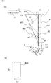
FIG. 1 is: (a) a side view illustrating a raw material charging device according to an embodiment of the present invention, and (b) a plan view for explaining a dimension of a second opening of a discharge port of the raw material charging device; -
FIG. 2 is a side view illustrating a device for processing electronic and electrical device part scraps according to an embodiment of the present invention; -
FIG. 3 is a partially enlarged plan view of the device for processing electronic and electrical device part scraps inFIG. 2 ; -
FIG. 4 is an explanatory view illustrating a raw material dropping region defined in a disperser; -
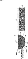
FIG. 5 is a photograph showing a dispersed state of a raw material to be processed, when the number of dispersed surfaces of a disperser is changed from 0 to 5; and -
FIG. 6 is a graph showing a relationship between an area ratio of a dispersed surface of a raw material dropping region and a weight distribution ratio of a raw material to be processed. - Hereinafter, embodiments of the present invention will be described with reference to the drawings. In descriptions of the drawings below, the same or similar portions are designated by the same or similar reference numerals. It should be noted that embodiments shown below illustrate devices and methods for embodying the technical idea of the present invention, and the technical idea of the present invention is not inteded to limit structures, arrangements, etc. of components to those described below.
- As shown in
FIG. 1 , a raw material supply device (raw material chute) 4 according to an embodiment of the present invention includes anaccommodating portion 41 for accommodating araw material 100 containing substances having different shapes and specific gravities, which is charged from a conveying unit (first conveying unit 2) for conveying theraw material 100 toward the front of the first conveyingunit 2, theaccommodating portion 41 feeding theraw material 100 to a predetermined position. Theaccommodating portion 41 includes a top surface; a bottom surface opposing to the top surface; and a side surface connected to the top surface and the bottom surface. - The raw
material supply device 4 includes: a receivingport 43 having afirst opening 433 for receiving theraw material 100 on the top surface of theaccommodating portion 41; and adischarge port 41 having asecond opening 422 for discharging theraw material 100 on the bottom surface of theaccommodating portion 41. Thesecond opening 422 has a lower cross-sectional area than that of thefirst opening 433. - The front of the side surface of the
accommodating portion 41, i.e., the side surface of theaccommodating portion 41 on the front side of the first conveyingunit 2 for discharging theraw material 100 forward, is provided with afirst guide surface 412 vertically extending from the receivingport 43 through thedischarge port 42 so as to be contacted with theraw material 100 charged toward the front side of the first conveyingunit 2 to guide theraw material 100 downward. - The
first guide surface 412 may be made of a material selected so as to have a strength enough to prevent deformation even if the material is brought into contact with electronic and electrical device part scraps and the like. For example, thefirst guide surface 412 can be formed of an elastic body such as a rubber, a metal, and a plastic. A coating or the like for promoting the dropping of theraw material 100 may be applied on the surface of thefirst guide surface 412. Further, thefirst guide surface 412 may be the same as the side surface on the front side of theaccommodating portion 41. The surface of the side surface of theaccommodating portion 41 facing thefirst guide surface 412, i.e., the rear side of the side surface of theaccommodating portion 41, is provided with asecond guide surface 411 having aninclined surface 411a that is continuous with thedischarge port 42 and is inclined with respect to a horizontal plane (HP). - The
raw material 100 released from the first conveyingunit 2 is dropped in the vertical direction while moving at least in the horizontal direction due to the conveyance by the first conveyingunit 2. In this case, variousraw materials 100 are charged into the receivingport 43 of the rawmaterial supply device 4 while describing different falling loci (parabolas) depending on influences of the shapes and specific gravities of theraw material 100 and a degree of aggregation of theraw material 100, and the like. - When falling from the first conveying
unit 2, a part of theraw material 100, which is repelled from the first conveyingunit 2 or the otherraw material 100 and released to the front side, is contacted with the surface of thefirst guide surface 412 and is guided to the lower part of theaccommodating portion 41. A part of theraw material 100 is then contacted with the surface of thesecond guide surface 411, which is theinclined surface 411a, and is further guided downward. Theraw material 100 thus proceeds downward between thefirst guide surface 412 and thesecond guide surface 411, and is dropped in the vertical direction from thesecond opening 422 of thedischarge port 42. - As shown in
FIG. 1 (b) , thesecond opening 422 of thedischarge port 42 has a rectangular shape, and it has: a first dimension S1 equal to or less than an effective width of the conveying surface of the first conveyingunit 2 in a first direction that is parallel to an effective width direction (a depth direction of the paper surface inFIG. 1 (a) ) of the conveying surface of the first conveyingunit 2 as shown inFIG. 1 (a) ; and a second dimension S2 in a second direction that is orthogonal to the first direction. For example, when the effective width of the first conveyingunit 2 is 600 mm, the first dimension S1 is set to be, for example, 600 mm or less, although not limited thereto. - The second dimension S2 is preferably such that clogging does not occur even if the
raw material 100 is stored in theaccommodating portion 41, and the second dimension S2 is from 0.5 to 10 times, preferably from 1 to 5 times the maximum diameter of theraw material 100. The shape of thesecond opening 422 is not limited to a rectangle, and it may be an ellipse or a shape in which corners of the rectangle are rounded, although not limited to the specific shapes. - As shown in
FIG. 1 (a) , thefirst guide surface 412 extending in the vertical direction in theaccommodating portion 41 extends such that the lowermost end portion of thefirst guide surface 412 is located below an intersection P of an extended line extending along the inclination direction of thesecond guide surface 411 with thefirst guide surface 412. By arranging thefirst guide surface 412 so as to extend in the vertical direction, theraw material 100 is easily brought into contact with thefirst guide surface 412 to guide theraw material 100 in the vertical direction. - If the
second guide surface 411 is also extended from thedischarge port 42, thedischarge port 42 is narrower and theraw material 100 may be easily clogged. Therefore, only thefirst guide surface 412 is preferably extended without extending thesecond guide surface 411. - An inclination angle θ2 of the
inclined surface 411a of thesecond guide surface 411 relative to the horizontal plane HP can be appropriately changed depending on the raw material to be processed. When processing electronic and electrical device part scraps, the inclination angle θ2 is preferably 45 to 85°, and more preferably 50 to 80°. The adjustment of the inclination angle θ2 can prevent theraw material 100 from being contacted with thefirst guide surface 412 to bounce off and deviate from the dropping range, thereby allowing theraw material 100 to be concentrated to the target position to drop it in the vertical direction more reliably. - As shown in
FIG. 2 , the rawmaterial supply device 4 shown inFIG. 1 can be suitably used for various processing devices to feed the raw material from theconveying surface 2a of thefirst conveying unit 2 comprised of a conveyor or the like to thefirst conveying surface 1a of thesecond conveying unit 1 located below thefirst conveying unit 2. The embodiment ofFIG. 2 illustrates an example applied to the device for processing electronic and electrical devise part scraps containing various substances having different shapes and specific gravities. - That is, the device for processing the electronic and electrical device part scraps according to the embodiment of the present invention can include: the
first conveying unit 2; the rawmaterial supply device 4 for supplying the raw material charged to the front of thefirst conveying unit 2 to a predetermined position; asecond conveying unit 1 for conveying the raw material, thesecond conveying unit 1 being provided below the rawmaterial supply device 4; and a pyramid-shaped disperser 3 having a plurality ofdispersion surfaces material supply device 4 in a plurality of directions on theconveying surface 1a of thesecond conveying unit 1, the pyramid-shaped disperser 3 being arranged on thesecond conveying unit 1. - The second conveying means 1 may suitably employ a conveyor or the like for conveying the raw material to a sorting portion (sorting machine) for physically sorting the raw material. As shown in
FIG. 3 , thesecond conveying unit 1 has a first width D1 in a direction orthogonal to a conveying direction A of the raw material. Thefirst conveying unit 2 has a second width D2 narrower than the first width D1 in a direction orthogonal to the conveying direction of the raw material. - If the second width D2 is too small and the first width D1 is too large, it may be difficult to disperse the raw material over the
entire conveying surface 1a from thefirst conveying unit 2 to the second conveying means 1. On the other hand, if the second width D2 is larger and the first width D1 is smaller, the raw material may protrude from the conveyingsurface 1a and fall on the outside of the conveyingsurface 1a. Therefore, it is preferable that each width is adjusted such that the first width D1 is from 2 to 5 times the second width D2, and more preferably, the first width D1 is from 2 to 3 times the second width D2. - As shown in
FIG. 2 , thedisperser 3 is provided on the conveyingsurface 1a below the first conveyingunit 2. As shown inFIG. 3 , thedisperser 3 includes a plurality ofdispersion surfaces FIG. 4 , fivedispersion surfaces 3a to 3e are provided, and each of the dispersion surfaces 3a to 3e has an isosceles triangle shape, although the shape and number are not limited thereto. - For example, it is sufficient to have two or more of the dispersion surfaces 3a to 3e, and an increased number of
dispersion surfaces 3a to 3e can further improve dispersibility of the raw material. However, if there are too many dispersion surfaces, it may be difficult to be designed, and it may also be difficult to control a direction where the raw materials are dispersed. The number of the dispersion surfaces 3a to 3e may be from about 2 to 10, and more preferably from about 3 to 7, and further preferably from 3 to 5. - More preferably, the dispersion surfaces 3a to 3e are provided in an odd number. The
disperser 3 is preferably arranged so as to be aligned on the conveyingsurface 1a such that onedispersion surface 3c of the dispersion surfaces 3a to 3e faces the conveying direction A of the conveyingsurface 1a. Such an arrangement can allow an increased amount of raw material to be fed to the front side (conveying direction) of thedisperser 3 while dispersing the raw material in the width direction. - The
disperser 3 is provided with the plurality ofdispersion surfaces 3a to 3e in the conveying direction of the raw material, and the rear side in the conveying direction, i.e., arear surface portion 3f opposing to the plurality ofdispersion surfaces 3a to 3e is a single surface extending perpendicularly to the conveyingsurface 1a, as shown inFIG. 3 . Therear surface portion 3f has a shape of an isosceles triangle that shares sides of thedispersion surface 3a and thedispersion surface 3e. That is, thedisperser 3 has a pyramid shape with a hexagonal bottom surface, which has fivedispersion surfaces 3a to 3e radially extending from an apex T (seeFIG. 3 ) at the uppermost portion in the supplying direction of the raw material, and therear surface portion 3f extending from the apex T vertically to the conveyingsurface 1a. - As shown in
FIG. 2 , each of the dispersion surfaces 3a to 3e is preferably an inclined surface that is inclined at an inclination angle θ1 with respect to the conveyingsurface 1a. Along the inclined surface, the raw material dropped from the first conveyingunit 2 are fed from the upper side to the lower side of thedisperser 3, so that the raw material can be dispersed in a plurality of directions on the conveyingsurface 1a as shown inFIG. 3 . - If the inclination angle θ1 formed by the conveying
surface 1a and each of the dispersed surfaces 3a to 3e is too small, the raw material may not be properly conveyed to the conveyingsurface 1a, which may cause clogging of the raw material. On the other hand, if the inclination angle θ1 formed by the conveyingsurface 1a and each of the dispersed surfaces 3a to 3e is too large, the raw material may rapidly fall onto the conveyingsurface 1a to damage the conveyingsurface 1a. The inclination angle θ1 formed by the conveyingsurface 1a and each of the dispersion surfaces 3a to 3e is preferably from 30 to 70°, and more preferably from 35 to 50°. - As shown in
FIG. 4 , thedisperser 3 defines a rawmaterial dropping region 31 for receiving the raw material dropped from the rawmaterial supply device 4 directly below thedischarge port 42 of the raw material in the rawmaterial supply device 4. The rawmaterial dropping region 31 is defined at a position directly below thedischarge port 42 of the rawmaterial supply device 4 when thedisperser 3 is viewed from the upper surface thereof. The rawmaterial dropping region 31 has a rectangular shape as with thedischarge port 42, has a width d2 in the conveying direction, and has a width d1 in the direction orthogonal to the conveying direction. The rawmaterial dropping region 31 is set such that the width d2 of the rawmaterial dropping region 31 in the conveying direction is the same as or slightly narrower than the second dimension S2 of thedischarge port 42 of the rawmaterial supply device 4. By arranging the rawmaterial dropping region 31 so as to drop selectively the raw material from thedischarge port 42 of the rawmaterial supply device 4 into the rawmaterial dropping region 31, the dispersion direction of the raw material by thedisperser 3 can be controlled. If the width d2 of the rawmaterial dropping region 31 in the conveying direction is wider than the size of thedischarge port 42 of the rawmaterial supply device 4, the dispersibility may be deteriorated. - Further, it is preferable that the shape of the
disperser 3 is adjusted such that the area ratios of the plurality ofdispersion surfaces 3a to 3e in the rawmaterial dropping region 31 are equal to each other. By adjusting the shape of thedisperser 3 such that the area ratios of the plurality ofdispersion surfaces 3a to 3e in the rawmaterial dropping region 31 are equal to each other, an amount of the raw material to be dropped on each of the dispersion surfaces 3a to 3e can be made uniform among the dispersion surfaces 3a to 3e, so that the raw materials can be more uniformly dispersed and supplied on the conveyingsurface 1a. - It is preferable that the
disperser 3 having the rawmaterial dropping region 31 and the rawmaterial supply device 4 are arranged at an appropriate distance from each other. As shown inFIG. 1 , a length L1 from the intersection P of the extended line extending in the inclination direction of thesecond guide surface 411 with thefirst guide surface 412 to the lowermost end portion of thefirst guide surface 412 can be adjusted to be about 0.5 to 1.5 times the maximum diameter of theraw material 100. A length L2 from the lowermost end portion of thefirst guide surface 412 to thedisperser 3 can be adjusted to be about 1.0 to 1.5 times the length L1. When the electronic and electrical device part scraps are used as theraw material 100, the appropriate adjustment of the lengths L1 and L2 can lead to reliable dropping of theraw material 100 in the rawmaterial dropping region 31. Typically, thedisperser 3 and the rawmaterial supply device 4 are arranged such that the length L2 from the lowermost end portion of thefirst guide surface 412 to thedisperser 3 is at a distance of from 20 to 100 mm, and more preferably from 50 to 80 mm, thereby more reliably dropping theraw material 100 in the rawmaterial dropping region 31 to enable theraw material 100 to be uniformly dispersed from thedisperser 3. - According to the raw
material supply device 4 and the device for processing the electronic and electrical device part scraps of the embodiment of the present invention, the rawmaterial supply device 4 and thedisperser 3 are arranged between the first conveyingunit 2 and the second conveyingunit 1, whereby the raw material containing substances having different shapes and specific gravities can be concentrated and dropped at the predetermined position, and the raw material can be more uniformly dispersed on the conveyingsurface 1a. - The raw
material supply device 4 and the device for processing electronic and electrical device part scraps as shown inFIGS. 1 to 4 are suitably applied to a sorting step for sorting electronic and electrical device part scraps using various sorters such as wind power sorters, metal sorters, color sorters, and sieving machines. - As used herein, the "electronic and electrical device part scraps" in the present embodiment refers to scraps obtained by crushing electronic and electrical devices such as waste home electric appliances, PCs, and mobile phones, recovering them and then crushing them to have an appropriate size. In the present embodiment, the crushing for obtaining the electronic and electrical device part scraps may be performed by an operator. However, crushed objects may be purchased on the market.
- The crushing method is carried out by any apparatus that is not limited to a specific apparatus, and may be carried out in sharing or shock manner. It is desirable to carry out crushing such that the shapes of the parts are maintained as much as possible. Therefore, the apparatus does not include one belonging to the category of a crusher for the purpose of fine crashing.
- The electronic and electrical device part scraps can be classified into part scrap consisting of synthetic resins (plastics) used for substrates, parts such as ICs and connectors, and casings; wire scraps; metals; film-shaped part scraps; powders generated by crushing or pulverizing; and others, and they can be further classified into subclasses depending on purposes of the processing. In the present embodiment, the electronic and electrical device part scraps that have been crushed to have a maximum diameter of 100 mm or more, and more typically 50 mm or less, and have a percentage of individual parts separated as part scraps of 70% or more in weight ratio may preferably be processed, although not limited thereto.
- By processing these various types of part scraps in a predetermined order, for example, when sorted materials are used in a copper smelting step, raw materials that have concentrated valuable metals including gold, silver, platinum, palladium, and copper can be obtained while reducing unwanted substances for the processing in the copper smelting step, for example, smelting inhibiting substances such as elements such as antimony (Sb) and nickel (Ni), resins, aluminum (Al), and iron (Fe) as much as possible.
- The sorting step can include at least one of a wind force sorting step, a magnetic force sorting step, an eddy current sorting step, a specific gravity sorting step, and an optical sorting step of optically sorting a metallic substance and a non-metallic substance. The raw material supply device according to the embodiment of the present invention is arranged in front of the sorter used in each of these sorting steps.
- For example, in the method for processing electronic and electrical device part scraps including a sorting step for sorting electronic and electrical device part scraps using the sorter, the electronic and electrical device part scraps are dropped via the raw
material supply device 4 onto the dispersion surfaces 3a to 3e of the pyramid-shapeddisperser 3 arranged on the conveyingsurface 1a to disperse the electronic and electrical device part scraps in the plurality of directions on the conveyingsurface 1a, in the method for supplying the electronic and electrical device part scraps onto the conveyingsurface 1a for conveying the electronic and electrical device part scraps to the sorter. - By using the
disperser 3 in combination with the rawmaterial supply device 4, the dispersibility of the electronic and electrical device part scraps on the conveyingsurface 1a can be further improved. That is, using the rawmaterial supply device 4 provided directly above thedisperser 3, the electronic and electrical device part scraps are dropped in the vertical direction from the discharge port of the rawmaterial supply device 4, and the electronic and electrical device part scraps onto the rawmaterial dropping region 31 defined on thedisperser 3 formed such that the area ratios of the plurality ofdispersion surfaces 3a to 3e are equal to each other, whereby the electronic and electrical device part scraps can be more evenly dispersed on the conveyingsurface 1a. - When the electronic and electrical device part scraps are supplied to the sorter, the method for processing electronic and electrical device part scraps according to the embodiment of the present invention can prevent the electronic and electrical devise part scraps in the form of non-dispersed aggregates from being charged into the sorter, so that malfunction or damage of the sorter can be prevented, and a decrease in a sorting efficiency of the sorter can also be suppressed.
- As described above, the present disclosure is not limited to the present embodiments, and the components may be modified and embodied without departing from the spirit of the present invention. Further, various inventions may be formed by appropriately combining a plurality of components disclosed in the present embodiments. For example, some components may be deleted from all the components shown in the present embodiments, or the respective components may be combined as appropriate.
- For example, although the present embodiment illustrates an example in which the raw material is supplied onto the
disperser 3 via the rawmaterial supply device 4, the rawmaterial supply device 4 may be omitted. When the rawmaterial supply device 4 is omitted, an excessively high height from the conveyingsurface 1a to the conveyingsurface 2a of the first conveyingunit 2 may cause the raw material to be processed to fall from the conveyingsurface 1a, or, cause, for example, angular electronic and electric device part scraps to hit on the conveyingsurface 1a to damage the conveyingsurface 1a. On the other hand, an excessively low height from the conveyingsurface 1a to the conveyingsurface 2a of the first conveyingunit 2 may cause the raw material to be processed to be concentrated on the conveyingsurface 1a without being well dispersed. The height of the conveyingsurface 2a of the first conveyingunit 2 with respect to the conveyingsurface 1a is preferably from 1.0 to 2.0 m, and typically from 1.2 to 1.6 m. - Examples of the present invention will be illustrated below. However, these Examples are provided for better understanding of the present embodiment and its advantages, and they are not intended to limit the invention.
- The raw
material supply device 4 as shown inFIG. 1 was manufactured in order to concentrate and drop the raw material in a specific range in the vertical direction. It is assumed that an effective width of a conveying surface of a conveyor above the rawmaterial supply device 4 is 600 mm, the maximum diameter of the raw material is from 50 to 70 mm, and a conveying speed of the raw material is 36 m/min. Used as the raw material were electronic and electrical device part scraps comprised of substrates, parts such as ICs and connectors, synthetic resins (plastics) used for housings, wire scraps, metals, film-shaped part scraps, powders generated by breaking and crushing, and other materials, and aluminum plates (20 mm x 50 mm x 0.5 mm). The size of thefirst opening 433 of the receivingport 43 was designed to be 600 mm × 320 mm. The first dimension S1 of thesecond opening 422 of thedischarge port 42 was designed to be 600 mm, and the second dimension was designed to be 50 mm. The length L1 from the intersection P of the extended line extending in the inclination direction of thesecond guide surface 411 with thefirst guide surface 412 to the lowermost end portion of thefirst guide surface 412 was 50 mm, and the length L2 from the lowermost end portion of theguide surface 412 to thedisperser 3 was 70 mm, and the arrangement position was adjusted such that the rawmaterial dropping region 31 of thedisperser 3 was directly below thesecond opening 422 of thedischarge port 42. In addition, the inclination angle θ2 of theinclined surface 411a of thesecond guide surface 411 was 70°. - The disperser with different numbers of dispersion surfaces were manufactured and a dispersion behavior of the raw material was evaluated. The disperser was made of a plastic corrugated cardboard and had from 2 to 5 dispersion surfaces. Each dispersion surface was in the form of an isosceles triangle, in which the bases of the respective triangles were equal to each other. The inclination angle of each dispersion surface with respect to the bottom surface of the disperser was designed to be 45°. As a raw material to be processed, an aluminum plate (20 × 50 × 0.5 mm) was used for easy evaluation. The results are shown in
FIG. 5 . - As shown in
FIG. 5 , it was found that the increased number of dispersed surfaces resulted in better dispersibility of the raw material to be processed. The number of dispersed surfaces of three or five, an odd number, can allow the raw material to be processed to be dispersed forward as compared with the case where the number of dispersed surfaces is an even number. - Various dispersers were manufactured, the relationship between the area ratio of each dispersion surface in the raw material dropping region and the weight distribution ratio was investigated by changing the discharged position of the discharge port from the raw material chute. As a result, it was found that the area ratio of each dispersed surface in the raw material dropping region and the weight distribution ratio were substantially proportional to each other (
FIG. 6 ). - Further, as shown in
FIG. 4 , the sorting test was conducted for a case where the areas (A to E) of the dispersion surfaces in the raw material dropping region of the disperser having five dispersion surfaces were equal and a case where the bases of the dispersion surfaces of the disperser were equal (see Table 1).[Table 1] A B C D E (a) Case of Equal Base Ratio Base Ratio 1.0 1.0 1.0 1.0 1.0 Area Ratio (%) 21 22 14 22 21 (b) Case of Equal Area Ratio Base Ratio 1.0 0.9 1.4 0.9 1.0 Area Ratio (%) 20 20 20 20 20 - It was found that although the raw material to be processed could not be more uniformly dispersed by making the bases of the dispersion surfaces equal, the uniform dispersion of the raw material to be processed could be further improved by setting the raw material dropping region and the disperser such that the areas (A to E) of the dispersion surfaces were equal.
- In the processing device as shown in
FIG. 1 , the electronic and electrical device part scraps and aluminum pieces as raw materials were dropped from the first conveying unit at a conveying speed of 36 m/min toward the rawmaterial supply device 4 to disperse the raw materials from thedisperser 3 on the conveyingsurface 1a on the second conveyingunit 1. The weights of the raw materials dropped onto the conveyingsurface 1a along the dispersion surfaces 3a to 3e (A to E inFIG. 4 ) of thedisperser 3 were determined. The results are shown in Table 2.[Table 2] Aluminum Plate Electronic And Electrical Device Part Scraps A B C D E Ave. A B C D E Ave. Weight (g) 173 182 192 180 171 180 171 182 184 197 166 180 Distribution Ratio (%) 19.3 20.3 21.4 20 19.1 20 19 20.2 20.4 21.9 18.4 20 Error (%) -3.6 1.4 6.9 0.1 -4.7 -5.0 1.1 2.2 9.4 -7.8 - In Table 2, the distribution ratio (%) represents a ratio of the weight of the raw material dispersed on each dispersion surface to the total weight of the raw material. The error (%) represents an error with respect to an ideal value when the entire raw material is evenly dispersed on each dispersion surface.
- As shown in Table 2, it is found that in both cases where the aluminum plate and the electronic and electrical device part scraps are used, the error of the distribution ratio within 10% can be achieved, and the disperser and the raw material supply device according to the present embodiment can be used to achieve more uniform dispersion with respect to the conveying
surface 1a. -
- 1
- second conveying unit
- 1a
- conveying surface
- 2
- first conveying unit
- 2a
- conveying surface
- 3
- disperser
- 3a-3e
- dispersion surface
- 4
- raw material supply device
- 31
- raw material dropping region
- 41
- accommodating portion
- 42
- discharge port
- 43
- receiving port
- 411
- second guide surface
- 411a
- inclined surface
- 412
- first guide surface
- 422
- second opening
- 433
- first opening
Claims (8)
- A raw material supply device, comprising an accommodating portion which accommodates a raw material dropped from a conveying unit for conveying the raw material toward a front of the conveying unit and which feeds the raw material to a predetermined position, the raw material containing substances having different shapes and specific gravities,wherein the raw material supply device comprises:a receiving port having a first opening for receiving the raw material on a top surface of the accommodation portion;a discharge port having a second opening for discharging the raw material on a bottom surface of the accommodating portion, the second opening having a cross-sectional area lower than that of the first opening;a first guide surface in a front of a side surface of the accommodating portion, the first guide surface extending in a vertical direction through the discharge port from the receiving port to so as to be contacted with the raw material dropped toward the front of the conveying unit to guide the raw material downward; anda second guide surface on a surface opposing to the first guide surface, of the side surface of the accommodating portion, the second guide surface being provided with an inclined surface that is continuous with the discharge port and is inclined with respect to a horizontal plane, andwherein the first guide surface extends such that a lowermost end portion of the first guide surface is located below an intersection of an extended line extending in an inclination direction of the second guide surface with the first guide surface.
- The raw material supply device according to claim 1, wherein the raw material supply device has: a first dimension equal to or less than an effective width of a conveying surface of the conveying unit in a first direction that is parallel to an effective width direction of the conveying surface of the conveying unit; and a second dimension in a second direction that is orthogonal to the first direction, the second dimension being from 0.5 to 10 times a maximum diameter of the raw material.
- A raw material supply device, comprising:a first conveying unit for conveying a raw material containing substances having different shapes and specific gravities;a second conveying unit for conveying the raw material to a processing device for processing the raw material, the second conveying unit being provided below the first conveying unit; anda pyramid-shaped disperser having a raw material dropping region for receiving the raw material fed from the first conveying unit, the disperser being arranged on a conveying surface of the second conveying unit, the disperser being provided with a plurality of dispersion surfaces for dispersing the raw material dropped in the raw material dropping region in a plurality of directions on the conveying surface of the second conveying unit.
- A device for processing electronic and electrical device part scraps, comprising:a first conveying unit for conveying a raw material containing substances having different shapes and specific gravities;the raw material supply device according to claim 1 or 2 for supplying the raw material charged from the first conveying unit to its front to a predetermined position;a second conveying unit for conveying the raw material to a processing device for processing the raw material, the second conveying unit being provided below the raw material supply device; anda pyramid-shaped disperser arranged on a conveying surface of the second conveying unit, the disperser being provided with a plurality of dispersion surfaces for dispersing the raw material supplied from the raw material supply device in a plurality of directions on the conveying surface of the second conveying unit.
- The device for processing electronic and electrical device part scraps according to claim 4, wherein the disperser has a raw material dropping region for receiving the raw material dropped from the raw material supply device, the disperser being provided below the discharge port of the raw material supply device, and wherein the disperser is arranged such that area ratios of the plurality of dispersion surfaces in the raw material dropping region are equal to each other.
- The device for processing electronic and electrical device part scraps according to claim 4 or 5, wherein a lowermost end portion of the first guide surface and the disperser are arranged at a distance of from 20 to 100 mm.
- A method for processing electronic and electrical device part scraps, comprising a sorting step for sorting electronic and electrical device part scraps using a sorter, wherein the sorting step comprises dropping the electronic and electrical device part scraps onto a plurality of dispersion surfaces of a pyramid-shaped disperser, and dispersing the electronic and electrical device part scraps in a plurality of directions on a conveying surface for conveying the electronic and electrical device part scraps to the sorter.
- The method for processing electronic and electrical device part scraps according to claim 7, wherein the method comprises supplying the electronic and electrical device part scraps onto the disperser via the raw material supply device according to claim 1 or 2.
Applications Claiming Priority (2)
| Application Number | Priority Date | Filing Date | Title |
|---|---|---|---|
| JP2018206162A JP6938450B2 (en) | 2018-10-31 | 2018-10-31 | Raw material supply equipment, electronic / electrical equipment parts waste treatment equipment, and electronic / electrical equipment parts waste treatment methods |
| PCT/JP2019/042697 WO2020090942A1 (en) | 2018-10-31 | 2019-10-30 | Raw material supply device, device for processing electronic and electric device part scraps, and method for processing electronic and electric device part scraps |
Publications (2)
| Publication Number | Publication Date |
|---|---|
| EP3875407A1 true EP3875407A1 (en) | 2021-09-08 |
| EP3875407A4 EP3875407A4 (en) | 2022-07-27 |
Family
ID=70462453
Family Applications (1)
| Application Number | Title | Priority Date | Filing Date |
|---|---|---|---|
| EP19878249.2A Withdrawn EP3875407A4 (en) | 2018-10-31 | 2019-10-30 | DEVICE FOR FEEDING RAW MATERIALS, DEVICE FOR PROCESSING RESIDUES OF PARTS OF ELECTRONIC AND ELECTRICAL DEVICES, AND METHOD FOR PROCESSING RESIDUES OF PARTS OF ELECTRONIC AND ELECTRICAL DEVICES |
Country Status (8)
| Country | Link |
|---|---|
| US (1) | US11649119B2 (en) |
| EP (1) | EP3875407A4 (en) |
| JP (1) | JP6938450B2 (en) |
| KR (1) | KR102524815B1 (en) |
| CN (1) | CN112930313B (en) |
| CA (1) | CA3118063C (en) |
| TW (2) | TWI730483B (en) |
| WO (1) | WO2020090942A1 (en) |
Families Citing this family (4)
| Publication number | Priority date | Publication date | Assignee | Title |
|---|---|---|---|---|
| JP6938450B2 (en) * | 2018-10-31 | 2021-09-22 | Jx金属株式会社 | Raw material supply equipment, electronic / electrical equipment parts waste treatment equipment, and electronic / electrical equipment parts waste treatment methods |
| JP7627168B2 (en) * | 2021-04-21 | 2025-02-05 | Jx金属株式会社 | Disposal method for waste electrical and electronic components |
| JP7264936B2 (en) * | 2021-04-21 | 2023-04-25 | Jx金属株式会社 | Electric/electronic component waste processing method and electric/electronic component waste processing apparatus |
| CN115231190B (en) * | 2022-08-18 | 2024-03-08 | 酒泉钢铁(集团)有限责任公司 | Homogenization feeding method for dry grinding dry separator |
Family Cites Families (40)
| Publication number | Priority date | Publication date | Assignee | Title |
|---|---|---|---|---|
| DE2119311A1 (en) * | 1971-04-21 | 1972-11-02 | Hauni-Werke Körber & Co KG, 2000 Hamburg | Method and device for removing rod-shaped articles |
| JPS5224936Y2 (en) * | 1971-09-21 | 1977-06-07 | ||
| US4031004A (en) * | 1976-05-24 | 1977-06-21 | Sommer Jr Edward J | Feed system for an electromagnetic eddy current materials separator |
| US4183192A (en) * | 1978-03-03 | 1980-01-15 | Marcal Paper Mills, Inc. | Method and apparatus for counting straws and the like |
| JPS5539953U (en) * | 1978-09-05 | 1980-03-14 | ||
| DE2942163A1 (en) * | 1979-10-18 | 1981-04-30 | Carl Schenck Ag, 6100 Darmstadt | METHOD AND DEVICE FOR DIVIDING A CONVEYOR CURRENT |
| JPS59144532U (en) * | 1983-03-16 | 1984-09-27 | 大和製衡株式会社 | Dispersion feeder for combination weighers |
| JPS6079125U (en) * | 1983-11-07 | 1985-06-01 | 株式会社石田衡器製作所 | Collection shot of automatic weighing equipment |
| JPS60126440U (en) * | 1984-01-31 | 1985-08-26 | 小川 周一 | Diffusion feeder |
| DE3573652D1 (en) | 1984-11-12 | 1989-11-16 | Ishida Scale Mfg Co Ltd | Automatic combinatorial weighing apparatus |
| DE3615769C1 (en) * | 1986-05-10 | 1987-05-27 | Orenstein & Koppel Ag | Conveyor belt system with discharge drum |
| JPS6412020U (en) * | 1987-07-14 | 1989-01-23 | ||
| KR960003772B1 (en) * | 1992-08-24 | 1996-03-22 | 현대전자산업주식회사 | Capacitor Manufacturing Method of Semiconductor Device |
| JPH07228319A (en) * | 1994-02-16 | 1995-08-29 | Tokai Rubber Ind Ltd | Chute inner wall protector |
| US5553968A (en) * | 1994-09-29 | 1996-09-10 | Astec Industries, Inc. | Method and apparatus for conveying and desegregating aggregate |
| JPH08131953A (en) * | 1994-11-02 | 1996-05-28 | Fuji Car Mfg Co Ltd | Waste separation method and apparatus |
| EP0800902B1 (en) * | 1996-04-11 | 2002-03-06 | Dieffenbacher Schenck Panel GmbH | Method for continuous manufacturing of a mat for boards of wooden or like material |
| DE29707143U1 (en) * | 1997-04-21 | 1997-07-03 | Kvaerner Panel Systems GmbH Maschinen- und Anlagenbau, 31832 Springe | Device for aligning and depositing elongated particles such as wood chips, wood fibers or the like. on a continuously moving surface |
| US6290055B1 (en) * | 1997-09-09 | 2001-09-18 | Paul Glorfield | Device for orienting and achieving the optimal density of a quantity of elongated objects |
| DE59800377D1 (en) * | 1997-11-05 | 2001-01-11 | Kraemer Ag Bassersdorf | VIBRATION CONVEYOR WITH DISTRIBUTION SOFT |
| US6135171A (en) * | 1999-03-18 | 2000-10-24 | Weakly; L. Alan | Passive enclosure dust control system |
| JP3591412B2 (en) * | 1999-05-31 | 2004-11-17 | 松下電器産業株式会社 | Crushing equipment |
| US20030127302A1 (en) * | 2001-01-31 | 2003-07-10 | Brewer Marvin Vincent | Regulatory gate system for product drop off of vibratory conveyors |
| KR100770300B1 (en) * | 2001-11-19 | 2007-10-25 | 주식회사 포스코 | Ore Dispersion Device in Separation Screen |
| US7063215B2 (en) * | 2002-06-24 | 2006-06-20 | Campbell Soup Company | Control systems and methods of dispensing items |
| TWM247566U (en) | 2003-11-25 | 2004-10-21 | Mei-Yun Li | Curved type transferring and connecting apparatus |
| US7228956B2 (en) * | 2005-01-10 | 2007-06-12 | Benetech, Inc. | Bulk material precision transfer chute apparatus |
| JP2009240846A (en) | 2008-03-28 | 2009-10-22 | Nichikon Seisakusho:Kk | Device for recycling aluminum |
| CN102510832B (en) * | 2009-07-09 | 2014-06-18 | 康尼格拉食品蓝姆威斯顿公司 | Article distribution and sorting system |
| JP2011162271A (en) | 2010-02-04 | 2011-08-25 | Mitsubishi Electric Corp | Bulk material carrying device |
| JP5582395B2 (en) * | 2010-06-30 | 2014-09-03 | 新日鐵住金株式会社 | Slag transfer device |
| JP5574876B2 (en) * | 2010-08-11 | 2014-08-20 | 鎌長製衡株式会社 | Gypsum waste material recycling equipment |
| JP5672182B2 (en) * | 2011-07-14 | 2015-02-18 | トヨタ自動車株式会社 | Nut arrangement device |
| CN102357468B (en) * | 2011-08-03 | 2014-02-05 | 合肥美亚光电技术股份有限公司 | Uniform material distribution apparatus of color sorter |
| WO2013061374A1 (en) * | 2011-10-27 | 2013-05-02 | 大和製衡株式会社 | Device for collecting and discharging objects to be weighed for combination scale, and combination scale using same |
| CN203143656U (en) * | 2012-12-30 | 2013-08-21 | 衡阳运输机械有限公司 | Improved receiving hopper |
| CN105358266B (en) * | 2013-04-25 | 2017-07-11 | 松下知识产权经营株式会社 | Substance sorting device, sorting method |
| CN205590014U (en) | 2016-04-08 | 2016-09-21 | 广东韶钢松山股份有限公司 | High -efficient chute of overhead paddle |
| US10099525B1 (en) * | 2018-06-20 | 2018-10-16 | Cal M. Phillips | Trailer hitch drawbar tightening mechanism |
| JP6938450B2 (en) * | 2018-10-31 | 2021-09-22 | Jx金属株式会社 | Raw material supply equipment, electronic / electrical equipment parts waste treatment equipment, and electronic / electrical equipment parts waste treatment methods |
-
2018
- 2018-10-31 JP JP2018206162A patent/JP6938450B2/en active Active
-
2019
- 2019-10-30 EP EP19878249.2A patent/EP3875407A4/en not_active Withdrawn
- 2019-10-30 KR KR1020217016178A patent/KR102524815B1/en active Active
- 2019-10-30 WO PCT/JP2019/042697 patent/WO2020090942A1/en not_active Ceased
- 2019-10-30 US US17/290,044 patent/US11649119B2/en active Active
- 2019-10-30 CN CN201980071140.9A patent/CN112930313B/en active Active
- 2019-10-30 CA CA3118063A patent/CA3118063C/en active Active
- 2019-10-31 TW TW108139490A patent/TWI730483B/en active
- 2019-10-31 TW TW110116370A patent/TWI794806B/en active
Also Published As
| Publication number | Publication date |
|---|---|
| JP6938450B2 (en) | 2021-09-22 |
| TW202136134A (en) | 2021-10-01 |
| TW202033427A (en) | 2020-09-16 |
| TWI794806B (en) | 2023-03-01 |
| US11649119B2 (en) | 2023-05-16 |
| CA3118063A1 (en) | 2020-05-07 |
| CA3118063C (en) | 2024-01-09 |
| JP2020070165A (en) | 2020-05-07 |
| KR20210082235A (en) | 2021-07-02 |
| TWI730483B (en) | 2021-06-11 |
| CN112930313A (en) | 2021-06-08 |
| CN112930313B (en) | 2022-09-13 |
| US20210403247A1 (en) | 2021-12-30 |
| WO2020090942A1 (en) | 2020-05-07 |
| KR102524815B1 (en) | 2023-04-24 |
| EP3875407A4 (en) | 2022-07-27 |
Similar Documents
| Publication | Publication Date | Title |
|---|---|---|
| US11649119B2 (en) | Raw material supply device, device for processing electronic and electrical device part scraps, and method for processing electronic and electrical device part scraps | |
| CN107952571B (en) | A kind of production method of Machine-made Sand | |
| US11548032B2 (en) | Method for removing wire-form objects, device for removing wire-form objects, and method for processing electronic/electrical apparatus component scrap | |
| US12090518B2 (en) | Method for processing electronic and electric device component scraps | |
| CN108212464B (en) | Crushing and sorting equipment and process thereof | |
| CN213855012U (en) | Novel distributing device before intelligent sorting | |
| JP2020037459A (en) | Raw material supply device and processing method for electronic/electrical equipment component scrap | |
| CN204220282U (en) | Belt magnetic plant and ore-sorting system | |
| CA3142590C (en) | RAW MATERIAL REMOVAL DEVICE, METHOD FOR TREATMENT OF ELECTRONIC/ELECTRICAL DEVICE COMPONENT DEBRIS, AND METHOD FOR RAW MATERIAL REMOVAL OF ELECTRONIC/ELECTRICAL DEVICE COMPONENT DEBRIS | |
| CN108855568B (en) | Stone production feeding crushing system | |
| CN223480333U (en) | Uniform feeding device for vibration screening operation | |
| CN223570877U (en) | Phosphate rock breaker | |
| CN214718487U (en) | Phosphorite photoelectric separator | |
| CN212189532U (en) | Feeding system of crusher | |
| CN115231190B (en) | Homogenization feeding method for dry grinding dry separator | |
| CN118218118A (en) | A control method for lead-zinc ore classification system | |
| JP2025081837A (en) | Sloping chute, chute device, and classification method for granular material | |
| JP2023035563A (en) | feeder | |
| JP2017115202A (en) | Sintering raw material granulation method and granulation equipment | |
| JPS63218287A (en) | Method and device for granulating slag | |
| KR20140035111A (en) | Apparatus for raw material |
Legal Events
| Date | Code | Title | Description |
|---|---|---|---|
| STAA | Information on the status of an ep patent application or granted ep patent |
Free format text: STATUS: THE INTERNATIONAL PUBLICATION HAS BEEN MADE |
|
| PUAI | Public reference made under article 153(3) epc to a published international application that has entered the european phase |
Free format text: ORIGINAL CODE: 0009012 |
|
| STAA | Information on the status of an ep patent application or granted ep patent |
Free format text: STATUS: REQUEST FOR EXAMINATION WAS MADE |
|
| 17P | Request for examination filed |
Effective date: 20210511 |
|
| AK | Designated contracting states |
Kind code of ref document: A1 Designated state(s): AL AT BE BG CH CY CZ DE DK EE ES FI FR GB GR HR HU IE IS IT LI LT LU LV MC MK MT NL NO PL PT RO RS SE SI SK SM TR |
|
| DAV | Request for validation of the european patent (deleted) | ||
| DAX | Request for extension of the european patent (deleted) | ||
| A4 | Supplementary search report drawn up and despatched |
Effective date: 20220624 |
|
| RIC1 | Information provided on ipc code assigned before grant |
Ipc: B07C 5/36 20060101ALI20220620BHEP Ipc: B65G 11/00 20060101ALI20220620BHEP Ipc: B65G 47/19 20060101AFI20220620BHEP |
|
| GRAP | Despatch of communication of intention to grant a patent |
Free format text: ORIGINAL CODE: EPIDOSNIGR1 |
|
| STAA | Information on the status of an ep patent application or granted ep patent |
Free format text: STATUS: GRANT OF PATENT IS INTENDED |
|
| INTG | Intention to grant announced |
Effective date: 20230228 |
|
| STAA | Information on the status of an ep patent application or granted ep patent |
Free format text: STATUS: THE APPLICATION IS DEEMED TO BE WITHDRAWN |
|
| 18D | Application deemed to be withdrawn |
Effective date: 20230711 |